WO2020067130A1 - 蓄電デバイス用弁装置及び蓄電デバイス - Google Patents
蓄電デバイス用弁装置及び蓄電デバイス Download PDFInfo
- Publication number
- WO2020067130A1 WO2020067130A1 PCT/JP2019/037534 JP2019037534W WO2020067130A1 WO 2020067130 A1 WO2020067130 A1 WO 2020067130A1 JP 2019037534 W JP2019037534 W JP 2019037534W WO 2020067130 A1 WO2020067130 A1 WO 2020067130A1
- Authority
- WO
- WIPO (PCT)
- Prior art keywords
- storage device
- power storage
- valve
- valve device
- container
- Prior art date
Links
Images


Classifications
-
- H—ELECTRICITY
- H01—ELECTRIC ELEMENTS
- H01M—PROCESSES OR MEANS, e.g. BATTERIES, FOR THE DIRECT CONVERSION OF CHEMICAL ENERGY INTO ELECTRICAL ENERGY
- H01M50/00—Constructional details or processes of manufacture of the non-active parts of electrochemical cells other than fuel cells, e.g. hybrid cells
- H01M50/30—Arrangements for facilitating escape of gases
- H01M50/317—Re-sealable arrangements
- H01M50/325—Re-sealable arrangements comprising deformable valve members, e.g. elastic or flexible valve members
- H01M50/333—Spring-loaded vent valves
-
- H—ELECTRICITY
- H01—ELECTRIC ELEMENTS
- H01G—CAPACITORS; CAPACITORS, RECTIFIERS, DETECTORS, SWITCHING DEVICES OR LIGHT-SENSITIVE DEVICES, OF THE ELECTROLYTIC TYPE
- H01G11/00—Hybrid capacitors, i.e. capacitors having different positive and negative electrodes; Electric double-layer [EDL] capacitors; Processes for the manufacture thereof or of parts thereof
- H01G11/14—Arrangements or processes for adjusting or protecting hybrid or EDL capacitors
- H01G11/18—Arrangements or processes for adjusting or protecting hybrid or EDL capacitors against thermal overloads, e.g. heating, cooling or ventilating
-
- H—ELECTRICITY
- H01—ELECTRIC ELEMENTS
- H01G—CAPACITORS; CAPACITORS, RECTIFIERS, DETECTORS, SWITCHING DEVICES OR LIGHT-SENSITIVE DEVICES, OF THE ELECTROLYTIC TYPE
- H01G11/00—Hybrid capacitors, i.e. capacitors having different positive and negative electrodes; Electric double-layer [EDL] capacitors; Processes for the manufacture thereof or of parts thereof
- H01G11/78—Cases; Housings; Encapsulations; Mountings
- H01G11/82—Fixing or assembling a capacitive element in a housing, e.g. mounting electrodes, current collectors or terminals in containers or encapsulations
-
- H—ELECTRICITY
- H01—ELECTRIC ELEMENTS
- H01M—PROCESSES OR MEANS, e.g. BATTERIES, FOR THE DIRECT CONVERSION OF CHEMICAL ENERGY INTO ELECTRICAL ENERGY
- H01M50/00—Constructional details or processes of manufacture of the non-active parts of electrochemical cells other than fuel cells, e.g. hybrid cells
- H01M50/10—Primary casings, jackets or wrappings of a single cell or a single battery
- H01M50/102—Primary casings, jackets or wrappings of a single cell or a single battery characterised by their shape or physical structure
- H01M50/105—Pouches or flexible bags
-
- H—ELECTRICITY
- H01—ELECTRIC ELEMENTS
- H01M—PROCESSES OR MEANS, e.g. BATTERIES, FOR THE DIRECT CONVERSION OF CHEMICAL ENERGY INTO ELECTRICAL ENERGY
- H01M50/00—Constructional details or processes of manufacture of the non-active parts of electrochemical cells other than fuel cells, e.g. hybrid cells
- H01M50/10—Primary casings, jackets or wrappings of a single cell or a single battery
- H01M50/116—Primary casings, jackets or wrappings of a single cell or a single battery characterised by the material
- H01M50/117—Inorganic material
- H01M50/119—Metals
-
- H—ELECTRICITY
- H01—ELECTRIC ELEMENTS
- H01M—PROCESSES OR MEANS, e.g. BATTERIES, FOR THE DIRECT CONVERSION OF CHEMICAL ENERGY INTO ELECTRICAL ENERGY
- H01M50/00—Constructional details or processes of manufacture of the non-active parts of electrochemical cells other than fuel cells, e.g. hybrid cells
- H01M50/10—Primary casings, jackets or wrappings of a single cell or a single battery
- H01M50/116—Primary casings, jackets or wrappings of a single cell or a single battery characterised by the material
- H01M50/121—Organic material
-
- H—ELECTRICITY
- H01—ELECTRIC ELEMENTS
- H01M—PROCESSES OR MEANS, e.g. BATTERIES, FOR THE DIRECT CONVERSION OF CHEMICAL ENERGY INTO ELECTRICAL ENERGY
- H01M50/00—Constructional details or processes of manufacture of the non-active parts of electrochemical cells other than fuel cells, e.g. hybrid cells
- H01M50/10—Primary casings, jackets or wrappings of a single cell or a single battery
- H01M50/116—Primary casings, jackets or wrappings of a single cell or a single battery characterised by the material
- H01M50/124—Primary casings, jackets or wrappings of a single cell or a single battery characterised by the material having a layered structure
- H01M50/126—Primary casings, jackets or wrappings of a single cell or a single battery characterised by the material having a layered structure comprising three or more layers
- H01M50/129—Primary casings, jackets or wrappings of a single cell or a single battery characterised by the material having a layered structure comprising three or more layers with two or more layers of only organic material
-
- H—ELECTRICITY
- H01—ELECTRIC ELEMENTS
- H01M—PROCESSES OR MEANS, e.g. BATTERIES, FOR THE DIRECT CONVERSION OF CHEMICAL ENERGY INTO ELECTRICAL ENERGY
- H01M50/00—Constructional details or processes of manufacture of the non-active parts of electrochemical cells other than fuel cells, e.g. hybrid cells
- H01M50/10—Primary casings, jackets or wrappings of a single cell or a single battery
- H01M50/183—Sealing members
- H01M50/19—Sealing members characterised by the material
- H01M50/193—Organic material
-
- H—ELECTRICITY
- H01—ELECTRIC ELEMENTS
- H01M—PROCESSES OR MEANS, e.g. BATTERIES, FOR THE DIRECT CONVERSION OF CHEMICAL ENERGY INTO ELECTRICAL ENERGY
- H01M50/00—Constructional details or processes of manufacture of the non-active parts of electrochemical cells other than fuel cells, e.g. hybrid cells
- H01M50/30—Arrangements for facilitating escape of gases
- H01M50/317—Re-sealable arrangements
- H01M50/325—Re-sealable arrangements comprising deformable valve members, e.g. elastic or flexible valve members
-
- H—ELECTRICITY
- H01—ELECTRIC ELEMENTS
- H01M—PROCESSES OR MEANS, e.g. BATTERIES, FOR THE DIRECT CONVERSION OF CHEMICAL ENERGY INTO ELECTRICAL ENERGY
- H01M50/00—Constructional details or processes of manufacture of the non-active parts of electrochemical cells other than fuel cells, e.g. hybrid cells
- H01M50/30—Arrangements for facilitating escape of gases
- H01M50/35—Gas exhaust passages comprising elongated, tortuous or labyrinth-shaped exhaust passages
- H01M50/367—Internal gas exhaust passages forming part of the battery cover or case; Double cover vent systems
-
- H—ELECTRICITY
- H01—ELECTRIC ELEMENTS
- H01M—PROCESSES OR MEANS, e.g. BATTERIES, FOR THE DIRECT CONVERSION OF CHEMICAL ENERGY INTO ELECTRICAL ENERGY
- H01M50/00—Constructional details or processes of manufacture of the non-active parts of electrochemical cells other than fuel cells, e.g. hybrid cells
- H01M50/30—Arrangements for facilitating escape of gases
- H01M50/375—Vent means sensitive to or responsive to temperature
-
- H—ELECTRICITY
- H01—ELECTRIC ELEMENTS
- H01G—CAPACITORS; CAPACITORS, RECTIFIERS, DETECTORS, SWITCHING DEVICES OR LIGHT-SENSITIVE DEVICES, OF THE ELECTROLYTIC TYPE
- H01G11/00—Hybrid capacitors, i.e. capacitors having different positive and negative electrodes; Electric double-layer [EDL] capacitors; Processes for the manufacture thereof or of parts thereof
- H01G11/04—Hybrid capacitors
- H01G11/06—Hybrid capacitors with one of the electrodes allowing ions to be reversibly doped thereinto, e.g. lithium ion capacitors [LIC]
-
- H—ELECTRICITY
- H01—ELECTRIC ELEMENTS
- H01G—CAPACITORS; CAPACITORS, RECTIFIERS, DETECTORS, SWITCHING DEVICES OR LIGHT-SENSITIVE DEVICES, OF THE ELECTROLYTIC TYPE
- H01G11/00—Hybrid capacitors, i.e. capacitors having different positive and negative electrodes; Electric double-layer [EDL] capacitors; Processes for the manufacture thereof or of parts thereof
- H01G11/14—Arrangements or processes for adjusting or protecting hybrid or EDL capacitors
- H01G11/20—Reformation or processes for removal of impurities, e.g. scavenging
-
- H—ELECTRICITY
- H01—ELECTRIC ELEMENTS
- H01G—CAPACITORS; CAPACITORS, RECTIFIERS, DETECTORS, SWITCHING DEVICES OR LIGHT-SENSITIVE DEVICES, OF THE ELECTROLYTIC TYPE
- H01G11/00—Hybrid capacitors, i.e. capacitors having different positive and negative electrodes; Electric double-layer [EDL] capacitors; Processes for the manufacture thereof or of parts thereof
- H01G11/22—Electrodes
- H01G11/24—Electrodes characterised by structural features of the materials making up or comprised in the electrodes, e.g. form, surface area or porosity; characterised by the structural features of powders or particles used therefor
-
- H—ELECTRICITY
- H01—ELECTRIC ELEMENTS
- H01M—PROCESSES OR MEANS, e.g. BATTERIES, FOR THE DIRECT CONVERSION OF CHEMICAL ENERGY INTO ELECTRICAL ENERGY
- H01M2200/00—Safety devices for primary or secondary batteries
- H01M2200/20—Pressure-sensitive devices
-
- Y—GENERAL TAGGING OF NEW TECHNOLOGICAL DEVELOPMENTS; GENERAL TAGGING OF CROSS-SECTIONAL TECHNOLOGIES SPANNING OVER SEVERAL SECTIONS OF THE IPC; TECHNICAL SUBJECTS COVERED BY FORMER USPC CROSS-REFERENCE ART COLLECTIONS [XRACs] AND DIGESTS
- Y02—TECHNOLOGIES OR APPLICATIONS FOR MITIGATION OR ADAPTATION AGAINST CLIMATE CHANGE
- Y02E—REDUCTION OF GREENHOUSE GAS [GHG] EMISSIONS, RELATED TO ENERGY GENERATION, TRANSMISSION OR DISTRIBUTION
- Y02E60/00—Enabling technologies; Technologies with a potential or indirect contribution to GHG emissions mitigation
- Y02E60/10—Energy storage using batteries
-
- Y—GENERAL TAGGING OF NEW TECHNOLOGICAL DEVELOPMENTS; GENERAL TAGGING OF CROSS-SECTIONAL TECHNOLOGIES SPANNING OVER SEVERAL SECTIONS OF THE IPC; TECHNICAL SUBJECTS COVERED BY FORMER USPC CROSS-REFERENCE ART COLLECTIONS [XRACs] AND DIGESTS
- Y02—TECHNOLOGIES OR APPLICATIONS FOR MITIGATION OR ADAPTATION AGAINST CLIMATE CHANGE
- Y02P—CLIMATE CHANGE MITIGATION TECHNOLOGIES IN THE PRODUCTION OR PROCESSING OF GOODS
- Y02P70/00—Climate change mitigation technologies in the production process for final industrial or consumer products
- Y02P70/50—Manufacturing or production processes characterised by the final manufactured product
-
- Y—GENERAL TAGGING OF NEW TECHNOLOGICAL DEVELOPMENTS; GENERAL TAGGING OF CROSS-SECTIONAL TECHNOLOGIES SPANNING OVER SEVERAL SECTIONS OF THE IPC; TECHNICAL SUBJECTS COVERED BY FORMER USPC CROSS-REFERENCE ART COLLECTIONS [XRACs] AND DIGESTS
- Y02—TECHNOLOGIES OR APPLICATIONS FOR MITIGATION OR ADAPTATION AGAINST CLIMATE CHANGE
- Y02T—CLIMATE CHANGE MITIGATION TECHNOLOGIES RELATED TO TRANSPORTATION
- Y02T10/00—Road transport of goods or passengers
- Y02T10/60—Other road transportation technologies with climate change mitigation effect
- Y02T10/70—Energy storage systems for electromobility, e.g. batteries
Definitions
- the present disclosure relates to a valve device for a power storage device and a power storage device.
- Patent Document 1 discloses an electric double layer capacitor cell using a capacitor valve having a predetermined structure.
- an electric storage device provided with a valve device in preparation for generating gas inside the electric storage device.
- a higher degree of sealing performance is required inside the power storage device from the viewpoint of suppressing intrusion of moisture from the external environment into the power storage device.
- a main object of the present invention is to provide a valve device for a power storage device.
- the valve device is configured to detect a gas generated inside the housing body.
- the vacuum spraying method spraying method of JIS Z2331: 2006 “Helium leak test method” is used.
- the gas is generated inside the electricity storage device by setting the helium leak amount from the secondary side of the valve device to the primary side, which is measured in accordance with the method specified in " Have found that the gas can be released to the outside and that the invasion of moisture from the external environment can be highly suppressed. Since the intrusion of moisture from the external environment into the power storage device can be suppressed to a higher degree, for example, the life of the power storage device can be extended.
- a power storage device valve device that is attached to the housing of the power storage device including a power storage device element and a housing that houses the power storage device element therein,
- the valve device is configured to reduce the pressure when the pressure inside the container increases due to gas generated inside the container,
- the secondary side of the valve device is measured in a 25 ° C. environment in accordance with the method specified in “Vacuum spraying method (spray method)” of JIS Z2331: 2006 “He leak test method”.
- a helium leak amount from the gas to the primary side is 5.0 ⁇ 10 ⁇ 11 Pa ⁇ m 3 / sec or more and 5.0 ⁇ 10 ⁇ 6 Pa ⁇ m 3 / sec or less.
- the gas when a gas is generated inside a power storage device, the gas can be released to the outside, and the invasion of moisture from the external environment can be highly suppressed.
- FIG. 1 is a plan view of an electric storage device according to a first embodiment to which a valve device according to the present disclosure can be applied.
- FIG. 2 is a sectional view taken along line II-II of FIG. 1. It is a figure showing a container. It is a figure showing an example of section structure of packaging material.
- FIG. 2 is a plan view of the valve device according to Embodiment 1.
- FIG. 6 is a sectional view taken along the line VI-VI in FIG. 5.
- FIG. 7 is a sectional view taken along line VII-VII of FIG. 5.
- FIG. 8 is a cross-sectional view taken along the line VIII-VIII of FIG. 1 and is a diagram for explaining a mounting state of the valve device.
- FIG. 5 is a flowchart illustrating a procedure for manufacturing the power storage device. It is a figure which shows the operation
- FIG. 10 is a plan view of a valve device according to Embodiment 2. It is XII-XII sectional drawing of FIG.
- FIG. 13 is a plan view of a valve device according to Embodiment 3.
- FIG. 14 is a sectional view taken along the line XIV-XIV in FIG. 13.
- 13 is a plan view of a valve device according to Embodiment 4.
- FIG. FIG. 16 is a sectional view taken along the line XVI-XVI in FIG. 15.
- 15 is a plan view of a valve device according to Embodiment 5.
- FIG. 10 is a plan view of a valve device according to Embodiment 2. It is XII-XII sectional drawing of FIG.
- FIG. 13 is a plan view of a valve
- FIG. 15 is a plan view of a valve device according to Embodiment 6.
- FIG. 19 is a sectional view taken along line XIX-XIX in FIG. 18.
- 15 is a plan view of a valve device according to Embodiment 7.
- FIG. 21 is a sectional view taken along the line XXI-XXI in FIG. 20. It is a figure showing a situation at the time of attachment to a container of a valve device. It is a figure showing a section of a valve device in modification 1. It is a figure showing a section of a valve device in modification 2. It is a figure showing a section of a valve device in modification 3. It is a top view of the valve device in the modification 4.
- FIG. 29 is a sectional view taken along the line XXIX-XXIX of FIG. 28. It is a typical sectional view of the valve device used in the example. It is a figure which shows the operation
- a valve device for a power storage device is a valve device for a power storage device that is attached to the housing of a power storage device that includes a power storage device element and a housing that houses the power storage device element therein.
- the valve device for a power storage device according to the present disclosure is attached to the housing so as to communicate with the inside of the housing.
- the valve device according to an embodiment of the present disclosure is configured to reduce the pressure when the pressure inside the container increases due to the gas generated inside the container, and to reduce the pressure according to JIS under a 25 ° C. environment.
- the helium leak amount from the secondary side of the valve device to the primary side which is measured according to the method specified in “Vacuum spraying method (spray method)” of 2006 “Helium leak test method”, is 5. It is not less than 0 ⁇ 10 ⁇ 11 Pa ⁇ m 3 / sec and not more than 5.0 ⁇ 10 ⁇ 6 Pa ⁇ m 3 / sec.
- the power storage device valve device is a check valve that satisfies the helium leak amount.
- the valve device for a power storage device of the present disclosure in the evaluation of the airtightness of the valve device, adopts helium instead of the conventional atmosphere, and sets the helium leak amount in the above range, thereby improving the airtightness of the valve device. It can be accurate. Accordingly, when gas is generated inside the power storage device, the gas can be released to the outside, and the invasion of moisture (for example, water vapor in the atmosphere) from the external environment is highly suppressed. be able to. Therefore, for example, the life of the power storage device can be extended.
- moisture for example, water vapor in the atmosphere
- valve device for a power storage device will be described in detail.
- a numerical range indicated by “to” means “over” and “below”.
- the notation of 2 to 15 mm means 2 mm or more and 15 mm or less.
- a specific embodiment of a valve device for a power storage device described later will be described in detail with reference to the drawings. In the drawings, the same or corresponding parts have the same reference characters allotted, and description thereof will not be repeated.
- the valve device for a power storage device is a valve that is measured in a 25 ° C. environment in accordance with the method specified in “Vacuum spraying method (spray method)” of JIS Z2331: 2006 “Helium leak test method”.
- the amount of helium leaking from the secondary side to the primary side of the apparatus is set in the range of 5.0 ⁇ 10 ⁇ 11 Pa ⁇ m 3 / sec or more and 5.0 ⁇ 10 ⁇ 6 Pa ⁇ m 3 / sec or less.
- the valve mechanism is not particularly limited.
- the valve device includes a secondary side located outside the housing of the power storage device (that is, an external environment), and a primary side located inside the housing of the power storage device.
- the primary side of the valve device is the inside of the housing, and in the valve device 200 in the schematic diagram of FIG.
- the secondary side of the valve device is the outside of the housing, and in the valve device 200 in the schematic diagram of FIG. 1, is the F direction side of the valve device.
- the upper limit of the helium leak amount is preferably about 4.5 ⁇ 10 ⁇ 6 Pa ⁇ m 3 / sec or less, more preferably about 1.0 ⁇ 10 ⁇ 6 Pa ⁇ m. m 3 / sec or less, more preferably about 1.0 ⁇ 10 ⁇ 7 Pa ⁇ m 3 / sec or less, more preferably about 1.0 ⁇ 10 ⁇ 8 Pa ⁇ m 3 / sec or less.
- 5.0 ⁇ 10 ⁇ 11 Pa ⁇ m 3 / sec or more, and a preferable range is from about 5.0 ⁇ 10 ⁇ 11 Pa ⁇ m 3 / sec to about 4.5 ⁇ 10 ⁇ 6 Pa ⁇ m 3 / sec.
- the helium leak amount is too small, it is difficult to stably release the gas generated inside the power storage device to the outside.
- the power storage device is used without opening such a valve device for a long period of time, a problem that the valve device cannot be properly opened easily occurs even when the internal pressure rises to a design value.
- the helium leak amount is in a range of about 5.0 ⁇ 10 ⁇ 11 Pa ⁇ m 3 / sec to about 2.0 ⁇ 10 ⁇ 10 Pa ⁇ m 3 / sec.
- the invasion of moisture from the external environment is particularly highly suppressed. can do.
- the shape of the portion where the valve seat of the valve mechanism and the ball contact with each other is designed with extremely high precision at a high level which is not performed by the conventional check valve. ⁇ It is necessary to process.
- the helium leak amount of the power storage device valve device of the present disclosure is a value measured by a helium leak test. Details of the measurement conditions of the helium leak test are as follows.
- Helium leak test The amount of helium leak from the secondary side to the primary side of the valve device is measured according to the method specified in JIS Z2331: 2006 “Vacuum spraying method (spray method)” of “Helium leak test method”. Specifically, a helium leak detector is used as a test device. In addition, the gas valve of the valve device is installed on a leak test jig (if a dummy valve device with a blocked gas valve is inserted, a jig that has been confirmed to have no helium leak) is connected to the test port. Helium leak detector. Check that there is no helium leak between the jig and the helium leak detector.
- vacuum is drawn to 13 Pa from the primary side of the valve device, and 99.99% helium gas is sprayed from the secondary side of the valve device to start measurement.
- the evaluation results are recorded with the spray being for 1-2 seconds and the waiting time being for 2-4 seconds.
- the same valve device is covered with a hood having a volume of 50 ml in accordance with the method specified in “Vacuum envelope method (vacuum hood method)” of JIS Z2331: 2006 “Helium leak test method”. You may wait for 20 seconds and confirm that the measurement results are the same.
- the measurement environment temperature is 25 ° C. in each case.
- the lower limit of the differential pressure between the primary side and the secondary side is preferably about 0.05 MPa or more, more preferably about 0.1 MPa.
- the upper limit is preferably about 1 MPa or less, more preferably about 0.3 MPa or less, and the preferred ranges are about 0.05 to 1 MPa, about 0.05 to 0.3 MPa, and 0.1 to 0.3 MPa. About 1 to 1 MPa and about 0.1 to 0.3 MPa.
- the set pressure inside the power storage device to which the valve device for a power storage device of the present disclosure is applied is set to a certain pressure or less.
- the set value of the internal pressure is appropriately set according to the type of the package with the valve device, but is preferably about 0.1 MPa or less, more preferably about 1.0 ⁇ 10 ⁇ 2 MPa or less. above about 1.0 ⁇ 10 -10 MPa, and examples of the preferred range of the internal pressure, 1.0 ⁇ 10 -10 ⁇ 0.1MPa approximately, 1.0 ⁇ 10 -10 ⁇ 1.0 ⁇ 10 - About 2 MPa.
- a power storage device to which the valve device for a power storage device of the present disclosure is applied includes a power storage device element, a housing, and a valve device.
- the container is made of, for example, metal.
- the shape of the container can be a round can, a square can, or the like.
- the container may be constituted by a laminate having at least a base material layer, a barrier layer, and a heat-fusible resin layer in this order.
- a preferred embodiment of the housing of the power storage device to which the valve device for a power storage device of the present disclosure is applied will be described later.
- the helium leak amount is set to 5.0 ⁇ 10 ⁇ 11 Pa ⁇ m 3 / sec or more and 5.0 ⁇ 10 ⁇ 6 Pa ⁇ m 3 / sec or less. Therefore, when gas is generated inside the power storage device, the gas can be released to the outside, and the invasion of moisture from the external environment can be highly suppressed.
- the helium leak amount can be set by a known method.
- materials, shapes, and sizes of members for example, a ball, a valve seat (for example, an O-ring), a spring, and a vent) to be described later that constitute a valve mechanism of the valve device, and a force of pressing the ball by the spring.
- the helium leak amount can be adjusted by designing. For example, by using an elastic body for one of a ball and a valve seat of a valve mechanism and using a high-hardness member such as a metal for the other, a helium leak amount is 5.0 ⁇ 10 ⁇ 11 Pa ⁇ m 3 / sec or more.
- the range it is easy to set the range to 5.0 ⁇ 10 ⁇ 6 Pa ⁇ m 3 / sec or less.
- it is effective to use an elastic body for both the ball and the valve seat of the valve mechanism.
- the inside of the power storage device may be reduced. Since it is difficult to appropriately release the generated gas to the outside, the material, shape, size, and the like of the members constituting the valve mechanism are appropriately adjusted.
- the helium leak amount can be easily designed in the above range.
- the helium leak amount is in the range of about 5.0 ⁇ 10 ⁇ 11 Pa ⁇ m 3 / sec to about 2.0 ⁇ 10 ⁇ 10 Pa ⁇ m 3 / sec, and further, 5.0.
- the valve is set at a high level which is not performed by the conventional check valve. It is necessary to design and process the shape of the portion where the valve seat of the mechanism and the ball contact with each other with extremely high accuracy. Preferably, it is effective to set the thickness to 1 ⁇ m or less.
- too high precision parts are brought into contact with each other, there is a problem that the valve device does not open properly, so that the surface roughness needs to be adjusted so that the helium leak amount falls within the above range.
- the valve device for a power storage device of the present disclosure include a first portion and a second portion.
- the first portion is a portion in which a valve mechanism for reducing the pressure when the pressure inside the container increases due to the gas generated inside the container is formed inside.
- the second portion is a portion in which a ventilation path for guiding gas generated inside the container to the valve mechanism is formed.
- the housing of the power storage device is configured by a laminate having at least a base layer, a barrier layer, and a heat-fusible resin layer in this order, heat-sealing is performed at the periphery of the housing.
- the conductive resin layers face each other.
- On the periphery of the container there is formed a peripheral joint where the opposite heat-fusible resin layers are fused to each other.
- the first portion is preferably located outside the edge of the peripheral joint. Further, at least a part of the second portion is sandwiched between the heat-fusible resin layers at the peripheral joining portion.
- this power storage device it is the second portion of the valve device that is sandwiched between the heat-fusible resin layers at the peripheral joining portion, and the first portion of the valve device is not sandwiched between the heat-fusible resin layers. Is preferred.
- this electric storage device a large pressure and heat are not applied to the first portion compared to the second portion when the opposing heat-fusible resin layers are fused.
- the valve device for an electric storage device it is possible to suppress the failure of the valve mechanism in the first portion due to the pressure and heat applied when the opposing heat-fusible resin layers are fused.
- the length of the first portion is longer than the length of the second portion, and a step may be formed at a boundary between the first portion and the second portion.
- the first portion is longer than the second portion at least in the thickness direction of the power storage device, and a step is formed at a boundary between the first portion and the second portion. Therefore, in this power storage device, when the second portion is sandwiched between the heat-fusible resin layers in the process of manufacturing the power storage device, even if the valve device is pushed too far into the housing, the step portion is caught on the end of the laminate. . Therefore, according to the power storage device, it is possible to suppress a situation in which the first portion is erroneously sandwiched between the heat-fusible resin layers in the process of manufacturing the power storage device.
- the thickness of the electric storage device at the portion where the second portion is sandwiched in the peripheral joint portion is compared with the case where no step is provided at the boundary between the first portion and the second portion.
- the difference between the length in the thickness direction and the length in the thickness direction of the power storage device in a portion where the second portion is not sandwiched among the peripheral edge joints is small. Therefore, in the portion where the second portion is sandwiched between the peripheral edge joining portions, the heat-fusible resin layers are fused to each other without applying excessive heat and pressure to the heat-fusible resin layers.
- the decrease in insulation property is a phenomenon in which a current is generated between the barrier (metal) layer and the electrolyte due to partial thinning or cracking of the heat-fusible resin.
- the length of the second portion in the width direction of the power storage device may be longer than the length of the second portion in the thickness direction of the power storage device.
- the length of the second portion in the thickness direction of the power storage device is shorter than when the cross-sectional shape of the second portion is a perfect circle (the same area).
- the length in the thickness direction of the power storage device at the portion where the second portion is sandwiched among the peripheral junctions, and the length of the power storage device at the portion where the second portion is not sandwiched among the peripheral junctions The difference from the length in the thickness direction is small. Therefore, in the portion where the second portion is sandwiched between the peripheral edge joining portions, the heat-fusible resin layers are fused to each other without applying excessive heat and pressure to the heat-fusible resin layers. As a result, according to this power storage device, it is possible to suppress a decrease in seal strength and a decrease in insulation due to the thinning of the heat-fusible resin layer.
- the second portion has a wing-like extending end portion that is formed so as to be thinner toward an end portion in the width direction of the electric storage device.
- the portion of the peripheral joint where the second portion is not interposed is sandwiched from the portion where the second portion is not interposed.
- the change in the thickness direction of the power storage device at the position where the power storage device moves to the portion where the power storage device moves is smooth. Therefore, no excessive force is applied to the laminate at the boundary between the position where the second portion is sandwiched between the heat-fusible resin layers and the position where the second portion is not sandwiched between the heat-fusible resin layers.
- this electricity storage device it is possible to appropriately fuse the heat-fusible resin layer without applying an excessive amount of heat or pressure to the heat-fusible resin layer. In addition, it is possible to suppress a decrease in insulation.
- the cross-sectional shape of the air passage may be circular.
- the length of the cross section of the ventilation path in the width direction of the power storage device may be longer than the length of the cross section of the ventilation path in the thickness direction of the power storage device.
- the second portion may have a pillar formed in the ventilation path.
- the outer surface of the second portion may be a pear.
- the second portion of the valve device can be firmly fixed to the housing as compared with the case where the outer surface of the second portion is smooth.
- At least one ridge extending in the circumferential direction may be formed on the outer surface of the second portion.
- the protruding ridges are securely in contact with the heat-fusible resin layer, they are easily fused to the laminate.
- the convex portion extends in the circumferential direction on the outer surface of the second portion. Therefore, according to this power storage device, the heat-fusible resin layer and the second portion can be fused in the circumferential direction of the second portion. Further, in this electric storage device, the contact area between the outer surface of the second portion and the heat-fusible resin is larger than that in the case where the convex portion is not formed in the second portion. Therefore, according to this power storage device, the second portion of the valve device can be relatively firmly fixed to the housing. In addition, by providing a plurality of ridges, it is possible to further firmly fix the second portion to the container.
- the corner of the end opposite to the first portion in plan view may be rounded.
- the possibility that the end damages the power storage device element in the housing is reduced. Can be. Further, according to the power storage device, the possibility that the end portion damages the heat-fusible resin layer inside the container and reduces the insulating property of the heat-fusible resin layer can be reduced.
- the outer shape of the cross section of the second portion having the center line of the ventilation path as a normal line is a polygon, and the corners of the polygon may be rounded.
- the portion of the second portion located in the housing is located inside the housing.
- the possibility of damaging the power storage device element can be reduced, and the portion of the second portion sandwiched between the heat-fusible resin layers damages the heat-fusible resin layers, The possibility of lowering the insulation of the device can be reduced.
- the power storage device for example, when the end of the second portion opposite to the first portion is sandwiched by the heat-fusible resin layer, the second portion is heat-fusible. The possibility of damaging the resin layer and reducing the insulating property of the heat-fusible resin layer can be reduced.
- each of the first portion and the second portion is made of a different material, and the melting point of the material of the first portion may be higher than the melting point of the material of the second portion.
- the material of the first portion and the second portion is not particularly limited, and for example, resins such as polypropylene (PP), fluorine resin, polyester resin, polyimide resin, polycarbonate resin, acrylic resin, stainless steel, Metals such as aluminum are mentioned.
- this power storage device even if pressure and heat are applied to the second portion during fusion of the opposing heat-fusible resin layers, the melting point of the material of the first portion is higher than the melting point of the material of the second portion. Therefore, the possibility that the first portion is deformed by heat is low. Therefore, according to this power storage device, it is possible to suppress the failure of the valve mechanism in the first portion at the time of fusing the opposed heat-fusible resin layers.
- a plane may be formed on at least a part of the outer surface of at least one of the first portion and the second portion.
- the valve device since the flat surface is formed on the outer surface of the valve device, the rolling of the valve device is prevented. Therefore, according to this power storage device, the valve device does not roll when the valve device is attached to the housing, so that the valve device can be easily positioned.
- a power storage device and a valve device to which the valve device for a power storage device of the present disclosure is preferably applied will be exemplified.
- the power storage device and the valve device to which the valve device for a power storage device of the present disclosure is applied are not limited to the following.
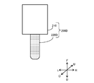
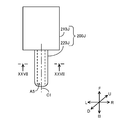
- FIG. 1 is a plan view of an electric storage device 10 according to the first embodiment.
- FIG. 2 is a sectional view taken along line II-II of FIG.
- the power storage device 10 has a configuration in which the positive electrode and the negative electrode of the tab 300 are arranged on opposite sides, and is designed for an electric vehicle such as an electric vehicle or a hybrid vehicle that uses a large number of power storage devices connected in series and uses a high voltage. .
- the power storage device 10 includes a housing 100, a power storage device element 400, a tab 300, a tab film 310, and a valve device 200.
- the container 100 includes the packaging materials 110 and 120. At the periphery of the container 100, the packaging materials 110 and 120 are heat-sealed to form a peripheral joint 130. That is, in the peripheral joint portion 130, the packaging materials 110 and 120 are fused to each other.
- the packaging materials 110 and 120 will be described later in detail.
- the power storage device element 400 is, for example, a power storage member such as a lithium ion power storage device or a capacitor.
- the power storage device element 400 is housed inside the housing 100.
- gas may be generated in the housing 100.
- power storage device element 400 is a capacitor, gas may be generated in container 100 due to a chemical reaction in the capacitor.
- the tab 300 is a metal terminal used for input / output of power in the power storage device element 400.
- One end of the tab 300 is electrically connected to an electrode (positive electrode or negative electrode) of the power storage device element 400, and the other end protrudes outward from an edge of the housing 100.
- the metal material forming the tab 300 is, for example, aluminum, nickel, copper or the like.
- tab 300 connected to the positive electrode is usually made of aluminum or the like
- tab 300 connected to the negative electrode is usually made of copper, nickel, or the like. You.
- the power storage device 10 includes two tabs 300.
- One tab 300 is sandwiched between packaging materials 110 and 120 via a tab film 310 at an end of the container 100 in the direction of the arrow L.
- the other tab 300 is sandwiched between packaging materials 110 and 120 via a tab film 310 at an end of the container 100 in the direction of arrow R.
- the tab film 310 is an adhesive protective film, and is configured to adhere to both the packaging materials 110 and 120 and the tab 300 (metal). By interposing the tab film 310, the metal tab 300 can be fixed with the packaging materials 110 and 120. Further, when the tab film 310 is used particularly at a high voltage, it is preferable that the tab film 310 contains a heat-resistant layer or a heat-resistant component and has a short-circuit preventing function.
- the valve device 200 communicates with the inside of the container 100, and when the pressure in the container 100 becomes equal to or higher than a predetermined value due to the gas generated in the container 100, the gas in the container 100. To the outside.
- the casing of the valve device 200 is preferably made of a material that directly adheres to the innermost layers of the packaging materials 110 and 120, and a resin having the same heat-fusing property as the innermost layers of the packaging materials 110 and 120, for example, polypropylene (PP). And the like. If a different material other than PP is used for reasons such as heat resistance, it is effective to seal with a heat-sealing film that can be bonded to both the different material and PP, like the tab film used for the tab. It is.
- the end of the valve device 200 in the direction of arrow B is sandwiched between the packaging materials 110 and 120 at the end of the container 100 in the direction of arrow F. The valve device 200 will be described later in detail.
- valve device 200 In power storage device 10 according to the first embodiment, various structural devices are employed to attach valve device 200 to housing 100.
- the configuration of the container 100, the configuration of the valve device 200, the state of attachment of the valve device 200 to the container 100, and the method of manufacturing the power storage device 10 will be sequentially described.
- each of the arrows LRUDFFB is common in each drawing.
- the direction of arrow LR is also referred to as “the width direction of power storage device 10”
- the direction of the arrow UD is also referred to as “the thickness direction of power storage device 10”.
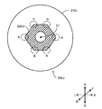
- FIG. 3 is a diagram illustrating the container 100.
- the container 100 includes packaging materials 110 and 120.
- Each of the packaging materials 110 and 120 is formed of a so-called laminate film, and has a substantially identical rectangular shape in plan view.
- the packaging material 110 includes a molded portion 112 molded so as to form the space S1, and a flange portion 114 extending from the molded portion 112 in the arrow FB direction and the arrow LR direction.
- the surface in the direction of the arrow U is open.
- Power storage device element 400 (FIG. 1) is arranged in space S1 through the open surface.
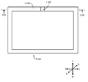
- FIG. 4 is a diagram showing an example of a cross-sectional structure of the packaging materials 110 and 120.
- each of the packaging materials 110 and 120 is a laminate in which a base material layer 31, an adhesive layer 32, a barrier layer 33, an adhesive layer 34, and a heat-fusible resin layer 35 are laminated in this order. It is.
- each of the packaging materials 110 and 120 does not necessarily need to include each layer shown in FIG. 4, as long as it has at least the base layer 31, the barrier layer 33, and the heat-fusible resin layer 35 in this order. Good.
- the base material layer 31 is the outermost layer
- the heat-fusible resin layer 35 is the innermost layer.
- the heat-fusible resin layers 35 located on the periphery of each of the packaging materials 110 and 120 in a state where the electric storage device element 400 (FIG. 2) is arranged in the space S1 (FIG. 3). Is thermally fused to form a peripheral joint 130, the power storage device element 400 is sealed in the housing 100, the valve device 200 is fused and fixed to the peripheral joint 130, and the tab 300 is also It is fused and fixed to the peripheral joining portion 130 via the tab film 310.
- the thickness of the packaging materials 110 and 120 is, for example, about 50 to 200 ⁇ m, preferably about 90 to 150 ⁇ m.
- the base material layer 31 is a layer that functions as a base material of the packaging materials 110 and 120, and is a layer that forms the outermost layer side of the container 100.
- the material for forming the base material layer 31 is not particularly limited as long as it has insulating properties.
- Examples of the material forming the base layer 31 include polyester, polyamide, epoxy, acrylic, fluororesin, polyurethane, silicon resin, phenol, polyetherimide, polyimide, polycarbonate, and mixtures and copolymers thereof.
- the base layer 31 may be, for example, a resin film formed of the above resin, or may be formed by applying the above resin.
- the resin film may be an unstretched film or a stretched film. Examples of the stretched film include a uniaxially stretched film and a biaxially stretched film, and a biaxially stretched film is preferable.
- the base material layer 31 may be a single layer, or may be composed of two or more layers.
- the base layer 31 may be a laminate in which a resin film is laminated with an adhesive or the like, or may be formed by co-extruding a resin and forming two or more layers. It may be a laminated body of a resin film obtained. Further, a laminate of two or more resin films obtained by co-extrusion of a resin may be used as the base material layer 31 without stretching, or may be used as the base material layer 31 by uniaxial stretching or biaxial stretching.
- the laminate of the resin film in which the base material layer 31 is two or more layers
- a laminate of a polyester film and a nylon film a laminate of two or more nylon films, a laminate of two or more polyester films
- Preferred are a laminate of a stretched nylon film and a stretched polyester film, a laminate of two or more stretched nylon films, and a laminate of two or more stretched polyester films.
- the base layer 31 is a laminate of a two-layer resin film, a laminate of a polyester resin film and a polyester resin film, a laminate of a polyamide resin film and a polyamide resin film, or a laminate of a polyester resin film and a polyamide resin film.
- a laminate is preferable, and a laminate of a polyethylene terephthalate film and a polyethylene terephthalate film, a laminate of a nylon film and a nylon film, or a laminate of a polyethylene terephthalate film and a nylon film is more preferable. Further, it is preferable that the polyester resin is located in the outermost layer of the base material layer 31.
- the thickness of the base layer 31 is, for example, about 3 to 50 ⁇ m, preferably about 10 to 35 ⁇ m.
- the adhesive layer 32 is a layer that is disposed as necessary on the base layer 31 in order to impart adhesion to the base layer 31. That is, the adhesive layer 32 is provided between the base layer 31 and the barrier layer 33 as needed.
- the adhesive layer 32 is formed of an adhesive capable of bonding the base layer 31 and the barrier layer 33.
- the adhesive used to form the adhesive layer 32 may be a two-part curable adhesive or a one-part curable adhesive.
- the bonding mechanism of the adhesive used for forming the adhesive layer 32 is not particularly limited, and may be any of a chemical reaction type, a solvent evaporation type, a hot-melt type, and a thermocompression bonding type.
- the thickness of the adhesive layer 32 is, for example, about 1 to 10 ⁇ m, preferably about 2 to 5 ⁇ m.
- the barrier layer 33 is a layer that has a function of preventing the invasion of water vapor, oxygen, light, and the like into the power storage device 10 in addition to improving the strength of the packaging materials 110 and 120.
- the metal forming the barrier layer 33 include aluminum, stainless steel, titanium, and the like, and preferably aluminum.
- the barrier layer 33 can be formed of, for example, a metal foil, a metal vapor-deposited film, an inorganic oxide vapor-deposited film, a carbon-containing inorganic oxide vapor-deposited film, and a film provided with these vapor-deposited films. Preferably, it is more preferably formed of aluminum foil.
- the barrier layer is made of, for example, annealed aluminum (JIS H4160: 1994 A8021H-O, JIS H4160: 1994).
- A8079H-O, JIS H4000: 2014 A8021P-O, JIS H4000: 2014 A8079P-O) and the like are more preferably formed of a soft aluminum foil.
- the thickness of the barrier layer 33 is not particularly limited as long as it functions as a barrier layer for water vapor or the like, but can be, for example, about 10 to 100 ⁇ m, preferably about 20 to 80 ⁇ m.
- the adhesive layer 34 is a layer provided as needed between the barrier layer 33 and the heat-fusible resin layer 35 in order to firmly adhere the heat-fusible resin layer 35.
- the adhesive layer 34 is formed of an adhesive capable of adhering the barrier layer 33 and the heat-fusible resin layer 35.
- the composition of the adhesive used to form the adhesive layer 34 is not particularly limited, but is, for example, a resin composition containing an acid-modified polyolefin.
- the acid-modified polyolefin is not particularly limited as long as it is an acid-modified polyolefin, but preferably includes a polyolefin graft-modified with an unsaturated carboxylic acid or an anhydride thereof.
- the thickness of the adhesive layer 34 is, for example, about 1 to 50 ⁇ m, preferably about 2 to 40 ⁇ m.
- the heat-fusible resin layer 35 forms the innermost layer of the container 100.
- the heat-fusible resin layer 35 is heat-sealed with the opposing heat-fusible resin layer at the periphery of the container 100 to seal the power storage device element 400 in the container 100.
- the heat-fusible resin covers the barrier layer with a certain thickness or more, the insulation between the electrolytic solution and the metal of the barrier layer can be maintained.
- the resin component used in the heat-fusible resin layer 35 is not particularly limited as long as it can be heat-fused, and is, for example, a polyolefin, an acid-modified polyolefin, or the like.
- polystyrene resin examples include polyethylene such as low-density polyethylene, medium-density polyethylene, high-density polyethylene, and linear low-density polyethylene; homopolypropylene, block copolymers of polypropylene (eg, block copolymers of propylene and ethylene), and random copolymers of polypropylene ( For example, crystalline or amorphous polypropylene such as a random copolymer of propylene and ethylene); terpolymer of ethylene-butene-propylene; Among these polyolefins, polyethylene and polypropylene are preferred.
- the acid-modified polyolefin is not particularly limited as long as it is an acid-modified polyolefin, but preferably includes a polyolefin graft-modified with an unsaturated carboxylic acid or an anhydride thereof.
- the thickness of the heat-fusible resin layer 35 is not particularly limited, but is preferably 100 ⁇ m or less, more preferably about 15 to 90 ⁇ m, and further preferably about 30 to 80 ⁇ m.
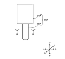
- FIG. 5 is a plan view of the valve device 200.
- the valve device 200 includes a valve function unit 210 and a seal mounting unit 220.
- the seal mounting portion 220 is a portion that is fixed by being sandwiched between the packaging materials 110 and 120 (FIG. 2).
- the outer peripheral surface of 220 and the heat-fusible resin layer 35 which is the innermost layer of the packaging materials 110 and 120 are in a state of being fused and joined.
- rounded corners are expressed as “R is formed”.
- R is formed means a state in which the corner is rounded similarly to the case where chamfering is performed, and further, “R” alone is Used to mean radius of rounded corners.
- the sharp corner generated in the manufacturing process of the valve device 200 may be chamfered to round the corner (form R), but the casing of the valve device 200 is formed of a resin molded product. In the case of R, it is also possible to form R without chamfering such as cutting by shaping from the beginning so as to have rounded corners.
- FIG. 6 is a sectional view taken along the line VI-VI in FIG.
- the cross section of each of the valve function part 210 and the seal attachment part 220 is a perfect circle, and a ventilation path A1 is formed inside the seal attachment part 220.
- the cross section of the ventilation path A1 is a perfect circle.
- the length L2 of the valve function unit 210 in the thickness direction (the direction of the arrow UD) of the power storage device 10 is longer than the length L1 of the seal attachment unit 220 in the thickness direction of the power storage device 10.
- the length L2 of the valve function unit 210 in the width direction (the direction of the arrow LR) of the power storage device 10 is longer than the length L1 of the seal attachment unit 220 in the width direction of the power storage device 10. That is, the cross-sectional diameter of the valve function section 210 is longer than the cross-sectional diameter of the seal mounting section 220.
- a step is formed at the boundary between the valve function part 210 and the seal mounting part 220 (FIG. 5).
- valve function unit 210 configured to discharge gas generated in the container 100 (FIG. 1) is provided inside the valve function unit 210.
- the valve function unit 210 includes a valve seat 212, a ball 214, a spring 216, and a membrane 218. That is, the valve function section 210 is provided with a ball spring type valve mechanism.
- the valve mechanism provided in the valve function unit 210 is not particularly limited as long as the pressure in the container 100 that has risen due to the gas can be reduced.
- valve seat 212 may be, for example, an O-ring, or a portion of the housing of the valve function unit 210 that contacts the ball 214 may be used as the valve seat 212.
- the housing of the valve function unit 210 is used as the valve seat 212, the housing of the valve function unit 210 and the valve seat 212 are integrated.
- the valve seat is made of an elastic material such as fluoro rubber, a metal such as stainless steel, a resin, or the like.
- the surface of the valve seat may be coated with PTFE, perfluoroalkoxy fluororesin (PFA), or the like.
- the ball 214 may be made of an elastic material such as fluoro rubber.
- the hardness of the elastic body such as fluororubber is not particularly limited, but the lower limit is preferably about 30 or more, more preferably about 50 or more, and the upper limit is preferably about 100 or less, more preferably about 90 or less.
- the preferable range includes about 30 to 100, about 30 to 90, about 50 to 100, and about 50 to 90.
- the hardness of the elastic body is a durometer type A hardness according to JIS K 6253-3.
- the ball 214 may be made of a metal such as stainless steel or a resin such as PTFE.
- the helium leak amount is reduced to 5.0 ⁇ 10 ⁇ 11 Pa ⁇ m. It is easy to set the range to 3 ⁇ / sec or more and 5.0 ⁇ 10 ⁇ 6 Pa ⁇ m 3 / sec or less.
- the valve seat and the ball are made of a combination of different metals, the helium leak amount can be easily set in the above range.
- the helium leak amount is in the range of about 5.0 ⁇ 10 ⁇ 11 Pa ⁇ m 3 / sec to 2.0 ⁇ 10 ⁇ 10 Pa ⁇ m 3 / sec, and further, 5.0 ⁇ 10 ⁇ 11.
- the valve seat of the valve mechanism is set at a high level which is not performed by the conventional check valve. It is necessary to design and process the shape of the portion where the ball contacts the ball with extremely high precision.
- both the valve seat and the ball are made of stainless steel.
- the spring 216 is made of, for example, stainless steel.
- Membrane 218, for example, 10 -2 to have 10 0 [mu] m approximately pore diameter (pore For diameter), without leaking the electrolyte is composed of a PTFE membrane as the only gas permeable (permselective).
- PTFE means polytetrafluoroethylene (polytetrafluoroethylene).
- FIG. 7 and the like show a diagram in which the membrane 218 is provided in the valve function unit 210.
- the membrane 218 is used. 218 is preferably provided in the seal attachment part 220 (for example, the ventilation path A1).
- the valve function may be impaired by a crystal component of the electrolytic solution or the like.
- the shape of the ball may be, for example, spherical, but it is not always necessary to be spherical, since the portion where the ball and the valve seat come into contact may be a corresponding shape, and may be, for example, hemispherical. However, the shape may be oblong or oblate. Further, for example, when the ball is hemispherical, a columnar member may extend from a flat surface.
- the gas guided from the ventilation path A1 presses the ball 214 in the direction of arrow F.
- the gas in the container 100 passes through a gap formed between the ball 214 and the valve seat 212, passes through the membrane 218, and passes through the exhaust port O 1 through the container 100. Is discharged to the outside.
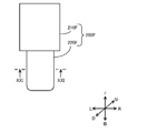
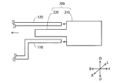
- FIG. 8 is a sectional view taken along the line VIII-VIII of FIG. 1, and is a view for explaining an attached state of the valve device 200.
- the valve function unit 210 of the valve device 200 is located outside the edge of the peripheral joint 130.
- a part of the seal mounting portion 220 of the valve device 200 is sandwiched between the heat-fusible resin layer 35 of the packaging material 110 and the heat-fusible resin layer 35 of the packaging material 120 at the peripheral joining portion 130. In this state, the outer peripheral surface of the seal mounting portion 220 and the heat-fusible resin layer 35 as the innermost layer of the packaging materials 110 and 120 are fused and joined.
- FIG. 8 is a sectional view taken along the line VIII-VIII of FIG. 1, and is a view for explaining an attached state of the valve device 200.
- the valve function unit 210 of the valve device 200 is located outside the edge of the peripheral joint 130.
- a part of the seal mounting portion 220 of the valve device 200 is sandwiched between the heat-fusible resin
- valve device 200 is described as being in a state of being fused and joined to the heat-fusible resin layer 35 which is the innermost layer of the packaging materials 110 and 120.
- the adhesive resin layer 35 is partially illustrated only in the vicinity of the peripheral joining portion 130, the heat-fusible resin layer 35 is provided on the entire surfaces of the packaging materials 110 and 120.
- seal attaching portion 220 is sandwiched between heat-fusible resin layers 35 at peripheral joining portion 130, and valve function portion 210 is attached to heat-fusible resin layer 35 at peripheral joining portion 130. The reason for not being sandwiched is described below.
- valve function part 210 is sandwiched between the heat-fusible resin layers 35 at the peripheral joint part 130.
- the valve mechanism in the valve function unit 210 fails due to the applied heat and pressure. there's a possibility that.
- seal attachment portion 220 is sandwiched between heat-fusible resin layers 35 at peripheral joining portion 130, and valve function unit 210 is attached to heat-fusible resin layer 35. Not sandwiched. Therefore, in the power storage device 10, large pressure and heat are not applied to the valve function unit 210 during heat sealing. That is, in the electricity storage device 10, failure of the valve mechanism due to pressure and heat applied at the time of heat sealing is suppressed by not sandwiching the valve function unit 210 between the heat-fusible resin layers 35.
- the diameter of the cross section of seal mounting portion 220 is shorter than the diameter of the cross section of valve function portion 210. Therefore, as compared with the case where the cross-sectional diameter of the seal mounting portion 220 is equal to or greater than the cross-sectional diameter of the valve function portion 210, the thickness direction of the power storage device in the portion of the peripheral joining portion 130 where the seal mounting portion 220 is sandwiched. Is small, and the length L3 in the thickness direction of the power storage device in a portion of the peripheral joining portion 130 where the seal attachment portion 220 is not sandwiched is small.
- the heat-fusible resin layer 35 which is the innermost layer of the packaging materials 110 and 120, so that the outer peripheral surface is joined without gaps. It is necessary to increase the pressure of the seal. As a result, the pressure applied to the periphery of the container 100 for heat sealing increases. When the pressure is increased, the heat-fusible resin layer 35 may be thinner particularly at the position where the seal attachment portion 220 is sandwiched, and further at the position where the tab film 310 and the tab 300 are sandwiched. When the heat-fusible resin layer 35 becomes thin, dielectric breakdown may occur in the power storage device 10.
- the difference between length L4 and length L3 is small. Therefore, when the periphery of the container 100 is sandwiched by the heat sealing machine, pressure and heat are appropriately applied to the heat-fusible resin layer 35 over the entire periphery of the container 100. As a result, according to the power storage device 10, the opposing heat-fusible resin layer 35 is appropriately fused while reducing the possibility of dielectric breakdown occurring in the power storage device 10, and the seal attachment portion 220 is attached to the container 100. Can be fixed firmly.
- the end of seal attachment portion 220 in the direction of arrow B projects into space S1 beyond flange 114. Therefore, the end of the seal mounting portion 220 in the direction of arrow B may come into contact with the power storage device element 400 depending on the usage state of the power storage device 10.
- R is formed at the end of seal mounting portion 220 in the direction of arrow B as described above (FIG. 5). Therefore, even if the end of the seal attaching portion 220 contacts the power storage device element 400, the possibility that the end damages the power storage device element 400 is low.
- the end of the seal attachment portion 220 in the direction of arrow B may come into contact with the heat-fusible resin layer 35 of the packaging material 120.
- R is formed at the end of seal mounting portion 220 in the direction of arrow B, so that the end of seal mounting portion 220 is temporarily Even if the edge contacts the heat-fusible resin layer 35, the possibility that the end portion damages the heat-fusible resin layer 35 is low.
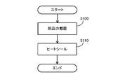
- FIG. 9 is a flowchart illustrating a procedure for manufacturing the power storage device 10.
- power storage device 10 is manufactured by a manufacturing apparatus.
- the manufacturing apparatus places each component in container 100 (step S100). For example, the manufacturing apparatus places the power storage device element 400, to which the tab 300 with the tab film 310 is electrically connected by welding, in the space S1 in the packaging material 110, so that the storage device element 400 is placed on the flange portion 114 of the packaging material 110. The tab 300 with the tab film 310 is placed, and then the valve device 200 is placed on the flange 114 of the packaging material 110. In addition, the electricity storage device element 400 is placed in the space S1 in the packaging material 110, and then the tab 300 with the tab film 310 is welded to the electricity storage device element 400 to be electrically connected, and the flange portion of the packaging material 110 is formed. It is also possible to place the tab 300 with the tab film 310 on the 114, and then place the valve device 200 on the flange 114 of the packaging material 110. Then, the manufacturing device places the packaging material 120 on the packaging material 110.
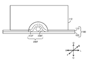
- FIG. 10 is a view showing an operation of placing the valve device 200 between the flange portion 114 of the packaging material 110 and the packaging material 120.
- a step is formed between the valve function part 210 and the seal attachment part 220. Therefore, when the seal mounting portion 220 is sandwiched between the packaging materials 110 and 120, even if the valve device 200 is pushed too far into the container 100, the step portion is caught by the ends of the packaging materials 110 and 120. Therefore, according to the power storage device 10, it is possible to suppress a situation in which the valve function unit 210 is erroneously sandwiched between the packaging materials 110 and 120 (the heat-fusible resin layer 35) in the manufacturing process of the power storage device 10.
- the tip of the seal mounting portion 220 of the valve device 200 may be arranged at a position sandwiched between the packaging materials 110 and 120.
- Step S110 the manufacturing apparatus heat seals the periphery of the container 100 (Step S110). That is, the manufacturing apparatus applies pressure and heat to the periphery of the container 100 with the periphery of the container 100 interposed therebetween. As a result, the heat-fusible resin layers 35 facing each other are fused to each other at the peripheral edge of the container 100, and the peripheral joint portion 130 is formed. Then, the power storage device element 400 is sealed in the housing 100, the valve device 200 is fused and fixed to the peripheral joint 130, and the tab 300 is also fused to the peripheral joint 130 via the tab film 310. And the power storage device 10 is completed.
- the shape of the surface of the seal bar of the manufacturing apparatus that sandwiches the periphery of the container 100 conforms to the outer shape of the seal mounting portion 220.
- the adhesion between the heat-fusible resin layers 35 at the position where the seal attachment portion 220 is sandwiched becomes stronger.
- valve device 10 in power storage device 10 according to the first embodiment, at least a part of seal attachment portion 220 of valve device 200 is sandwiched between heat-fusible resin layers 35 at peripheral joining portion 130, and the valve device The valve function portion 210 of the second embodiment is not sandwiched between the heat-fusible resin layers 35 at the peripheral joining portion 130. Therefore, in the power storage device 10, a large pressure and heat are not applied to the valve function unit 210 as compared with the seal attachment unit 220 when the opposing heat-fusible resin layer 35 is fused. As a result, according to the power storage device 10, it is possible to suppress the failure of the valve mechanism in the valve function unit 210 due to the pressure and heat applied when the opposing heat-fusible resin layer 35 is fused.
- the power storage device element 400 is an example of the “power storage device element” of the present disclosure
- the container 100 is an example of the “container” of the present disclosure
- the valve device 200 is the “valve device” of the present disclosure.
- the base layer 31 is an example of a “base layer” of the present disclosure
- the barrier layer 33 is an example of a “barrier layer” of the present disclosure
- the heat-fusible resin layer 35 is This is an example of the “fusible resin layer”.
- the peripheral joint 130 is an example of the “peripheral joint” of the present disclosure.
- the valve function part 210 is an example of the “first part” of the present disclosure
- the seal attaching part 220 is an example of the “second part” of the present disclosure.
- the air passage A1 is an example of the “air passage” of the present disclosure.
- the power storage device element 400 is housed in the space S1 in the housing 100
- the power storage device element 400 is shown in a small size with respect to the space S1 of the housing 100 for convenience.
- the space S1 is slightly larger than the power storage device element 400 in the manufacturing process, but is degassed as described above in the manufacturing process.
- the space S ⁇ b> 1 is slightly reduced due to the degassing and has substantially the same size as the power storage device element 400, and the power storage device element 400 is housed in the space S ⁇ b> 1 with almost no gap.
- Embodiment 2 The second embodiment differs from the first embodiment in the configuration of the valve device. Other configurations are basically the same as those of the first embodiment. Here, portions different from the first embodiment will be described.
- FIG. 11 is a plan view of valve device 200A mounted on the electric storage device according to the second embodiment.
- the valve device 200A includes a valve function part 210A and a seal mounting part 220A. At least a part of the seal attachment portion 220A is a portion that is heat-sealed by being sandwiched between the packaging materials 110 and 120.
- the seal mounting portion 220A has a different cross-sectional shape as compared with the first embodiment.
- the valve function part 210A is basically the same as that of the first embodiment, but according to the difference in the shape of the ventilation path A6 (FIG. 12) formed in the seal attachment part 220A, the housing and the valve mechanism. The shape of has been partially changed.
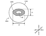
- FIG. 12 is a cross-sectional view taken along the line XII-XII of FIG.
- the length L5 of the power storage device in the width direction is longer than the length L6 of the power storage device in the thickness direction (the direction of the arrow UD).
- the cross-sectional shape of the seal mounting portion 220A is an elliptical shape.
- a ventilation passage A6 is formed inside the seal mounting portion 220A. Also in the ventilation path A6, the length of the power storage device in the width direction is longer than the length of the power storage device in the thickness direction. More specifically, the cross-sectional shape of the ventilation path A6 is an elliptical shape.
- the length L5 in the width direction of the power storage device is longer than the length L6 in the thickness direction of the power storage device in the cross section of the seal attachment portion 220A. That is, the length of the seal mounting portion 220A in the thickness direction of the power storage device is shorter than when the cross-sectional shape of the seal mounting portion is a perfect circle (the same area).
- the length in the thickness direction of the power storage device in a portion where the seal attachment portion 220A is sandwiched in the peripheral joining portion 130, and the power storage in a portion where the seal attachment portion 220A is not sandwiched in the peripheral joining portion 130 The difference from the length in the thickness direction of the device is smaller.
- the valve device 200A is an example of the “valve device” of the present disclosure
- the valve function unit 210A is an example of the “first portion” of the present disclosure
- the seal mounting unit 220A is the “second device” of the present disclosure.
- Part The air passage A6 is an example of the “air passage” of the present disclosure.
- Embodiment 3 differs from Embodiment 1 in the configuration of the valve device. Other configurations are basically the same as those of the first embodiment. Here, portions different from the first embodiment will be described.
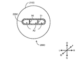
- FIG. 13 is a plan view of valve device 200B mounted on the electric storage device according to the third embodiment.
- the valve device 200B includes a valve function unit 210B and a seal mounting unit 220B. At least a part of the seal mounting portion 220B is a portion that is heat-sealed by being sandwiched between the packaging materials 110 and 120.
- the cross-sectional shape of the seal mounting portion 220B is different from that of the first embodiment.
- the valve function part 210B is basically the same as that of the first embodiment, but according to the difference in the shape of the ventilation path A7 (FIG. 14) formed in the seal attachment part 220B, the housing and the valve mechanism. The shape of has been partially changed.
- FIG. 14 is a cross-sectional view taken along the line XIV-XIV of FIG.
- wing-like extending ends 40 and 41 are formed at both ends in the width direction (the direction of the arrow LR) of the power storage device.
- Each of the wing-shaped extending ends 40 and 41 has a shape that becomes thinner as approaching the widthwise end of the power storage device.
- each of the wing-shaped extending ends 40 and 41 has a length in the thickness direction of the power storage device in the direction of the arrow LR as compared with the other portion (circular portion) of the seal attachment portion 220B. It can be said that the change is gradual.
- seal attachment portion 220B of peripheral joint portion 130 is different from the first embodiment.
- the change in the thickness direction of the power storage device at the position where the portion where the seal mounting portion 220 ⁇ / b> B is sandwiched from the portion where the seal attachment portion 220 ⁇ / b> B is not sandwiched is smooth. Therefore, according to this power storage device, at the boundary between the position where the seal attaching portion 220B is sandwiched by the heat-fusible resin layer 35 and the position where the seal attaching portion 220B is not sandwiched by the heat-fusible resin layer 35. Since no excessive force is applied to the packaging materials 110 and 120, the seal mounting portion 220B of the valve device 200B can be firmly fixed to the container 100.
- the valve device 200B is an example of the “valve device” of the present disclosure
- the valve function unit 210B is an example of the “first part” of the present disclosure
- the seal mounting unit 220B is the “second device” of the present disclosure.
- Part The wing-shaped extended ends 40 and 41 are examples of the “wing-shaped extended end” of the present disclosure.
- the air passage A7 is an example of the “air passage” of the present disclosure.
- Embodiment 4 differs from the first embodiment in the configuration of the valve device. Other configurations are basically the same as those of the first embodiment. Here, portions different from the first embodiment will be described.
- FIG. 15 is a plan view of valve device 200C mounted on the electric storage device according to the fourth embodiment.
- the valve device 200C includes a valve function unit 210C and a seal mounting unit 220C. At least a part of the seal mounting portion 220C is a portion that is heat-sealed by being sandwiched between the packaging materials 110 and 120.
- the seal mounting portion 220C has a different cross-sectional shape as compared with the first embodiment.
- the valve function part 210C is basically the same as that of the first embodiment, but according to the difference in the shape of the ventilation path A2 (FIG. 16) formed in the seal attachment part 220C, the housing and the valve mechanism. The shape of has been partially changed.
- FIG. 16 is a sectional view taken along the line XVI-XVI in FIG.
- pillars 50 and 51 are formed in the seal attachment portion 220C (in the ventilation path A2).
- Each of the pillars 50 and 51 extends in the thickness direction (the direction of the arrow UD) of the power storage device, and both ends in the thickness direction of the power storage device are connected to the inner periphery of the seal attachment portion 220C.
- Each of the pillars 50 and 51 extends in the direction of arrow FB in the ventilation path A2 (FIG. 15).
- the number of pillars does not necessarily need to be two, and at least one pillar is sufficient.
- the valve device 200C is an example of the “valve device” of the present disclosure
- the valve function unit 210C is an example of the “first part” of the present disclosure
- the seal mounting unit 220C is the “second portion” of the present disclosure.
- Part The pillars 50 and 51 are examples of the “pillar” of the present disclosure.
- the air passage A2 is an example of the “air passage” of the present disclosure.
- the fifth embodiment is different from the first embodiment in the configuration of the valve device. Other configurations are basically the same as those of the first embodiment. Here, portions different from the first embodiment will be described.
- FIG. 17 is a plan view of valve device 200D mounted on the electric storage device according to the fifth embodiment.
- the valve device 200D includes a valve function part 210 and a seal mounting part 220D.
- the configuration of the valve function unit 210 is the same as in the first embodiment.
- At least a part of the seal mounting portion 220D is a portion that is heat-sealed by being sandwiched between the packaging materials 110 and 120.
- the outer surface of seal mounting portion 220D is different from that of the first embodiment.
- the outer surface of the seal mounting portion 220D is a pear.
- the surface roughness Ra of the pear is, for example, 1 ⁇ m to 20 ⁇ m.
- the seal mounting portion 220D of the valve device 200D can be firmly fixed to the container 100 as compared with Embodiment 1 (when the outer surface of the seal mounting portion 220D is smooth). it can.
- valve device 200D is an example of the “valve device” of the present disclosure
- seal mounting portion 220D is an example of the “second portion” of the present disclosure.
- Embodiment 6 differs from the first embodiment in the configuration of the valve device. Other configurations are basically the same as those of the first embodiment. Here, portions different from the first embodiment will be described.
- FIG. 18 is a plan view of valve device 200E mounted on the electric storage device according to the sixth embodiment.
- the valve device 200E includes a valve function unit 210 and a seal mounting unit 220E.
- the configuration of the valve function unit 210 is the same as in the first embodiment.
- the seal mounting portion 220E is a portion where at least a part thereof is heat-sealed by being sandwiched between the packaging materials 110 and 120.
- the outer surface of the seal attachment portion 220E is different from that of the first embodiment.
- a protruding ridge portion 60 extending continuously in the circumferential direction is formed on the outer surface of the seal mounting portion 220E.
- the three protruding ridges 60 are formed in the arrow FB direction in the seal mounting portion 220E.
- the number of the ridges 60 is not necessarily three, and at least one ridge 60 may be formed.
- FIG. 19 is a sectional view taken along the line XIX-XIX in FIG. As shown in FIG. 19, the cross section of the ridge 60 is semicircular.
- the semicircular R is, for example, 0.05 mm to 1.0 mm.
- the diameter L12 (the length in the thickness direction of the power storage device and the length in the width direction of the power storage device) in the portion where the ridge 60 is formed in the seal attachment portion 220E does not include the ridge 60. It is longer than the diameter L11 of the portion.
- the protruding ridges 60 surely come into contact with the heat-fusible resin layer 35, so that they are easily fused to the packaging materials 110 and 120.
- ridge 60 extends continuously around the outer surface of seal mounting portion 220E in the circumferential direction. Therefore, according to this power storage device, the heat-fusible resin layer 35 and the seal attachment portion 220E can be fused together in one circumferential direction of the seal attachment portion 220E. Further, in this electric storage device, the contact between the outer surface of seal mounting portion 220E and the heat-fusible resin is different from that of the first embodiment (in the case where convex portion 60 is not formed in seal mounting portion 220E). Since the area is large, the seal mounting portion 220E of the valve device 200E can be firmly fixed to the packaging material 110.
- valve device 200E is an example of the “valve device” of the present disclosure
- seal mounting portion 220E is an example of the “second portion” of the present disclosure
- ridge 60 is an example of the “ridge” of the present disclosure
- air passage A3 is an example of the “air passage” of the present disclosure.
- the ridge 60 extends continuously in the circumferential direction.
- the ridge 60 may be formed on the entire circumference as long as it extends in the circumferential direction. It does not have to be continuous.
- the wing-shaped extending ends 40 and 41 are provided as in the above-described third embodiment, it is not necessary to provide the ridge 60 for making a full circle including the wing-shaped extending ends 40 and 41, and the wing-shaped extending end is not required.
- Embodiment 7 The seventh embodiment is different from the first embodiment in the configuration of the valve device. Other configurations are basically the same as those of the first embodiment. Here, portions different from the first embodiment will be described.
- FIG. 20 is a plan view of valve device 200F mounted on the electric storage device according to the seventh embodiment.
- the valve device 200F includes a valve function unit 210F and a seal mounting unit 220F. At least a part of the seal mounting portion 220F is a portion that is heat-sealed by being sandwiched between the packaging materials 110 and 120.
- the valve function part 210F and the seal attachment part 220F have different cross-sectional shapes as compared with the first embodiment.
- FIG. 21 is a cross-sectional view taken along the line XXI-XXI of FIG.
- the cross section of the valve function unit 210F has a semicircular shape. That is, the surface of the valve function unit 210F in the direction of the arrow U is flat.
- the cross section of the seal mounting portion 220F has wing-like extending ends 40F and 41F at both ends in the direction of the arrow LR.
- the surface of the seal mounting portion 220F in the direction of arrow U is flat.
- the surface of the valve function portion 210F in the direction of the arrow U and the surface of the seal mounting portion 220F in the direction of the arrow U are flush with each other.
- valve device 200F when the valve device 200F is arranged with the surface in the direction of the arrow U facing down, the valve device 200F does not roll. Therefore, according to the electric storage device according to the seventh embodiment, when mounting valve device 200F to container 100, valve device 200F does not roll, so that valve device 200F can be easily positioned.
- FIG. 22 is a diagram showing a state when the valve device 200F is attached to the container 100.
- the plane of the valve device 200F is placed on the surface of the innermost layer of the packaging material 120. In this state, the valve device 200F does not roll. Therefore, according to the electric storage device according to the seventh embodiment, when mounting valve device 200F to container 100, positioning of valve device 200F can be easily performed.
- the bulging of the peripheral joint 130 by the valve device 200F can be directed in the direction in which the container 100 swells, that is, in FIG.
- the valve device 200F is an example of the “valve device” of the present disclosure
- the valve function unit 210F is an example of the “first part” of the present disclosure
- the seal mounting unit 220F is the “second device” of the present disclosure.
- Part The air passage A4 is an example of the “air passage” of the present disclosure.
- the cross section of the seal attaching portion (the seal attaching portion 220 and the like) has a shape based on a circle.
- the cross-sectional shape of the seal mounting portion is not limited to this.
- the cross-sectional shape of the seal mounting portion may have a shape based on a polygon.
- FIG. 23 is a diagram showing a cross section of a valve device 200G according to the first modification.
- the cross section of the seal mounting portion 220G has a rhombic shape.
- length L7 in the width direction of the power storage device is longer than length L8 in the thickness direction of the power storage device.
- the length in the thickness direction of the power storage device in the portion where the seal attachment portion 220G is sandwiched in the peripheral joining portion 130 and the power storage in the portion where the seal attachment portion 220G is not sandwiched in the peripheral joint portion 130 The difference from the length in the thickness direction of the device is smaller.
- FIG. 24 is a view showing a cross section of the valve device 200H according to the second modification.
- the cross section of the seal attachment portion 220H has a rhombic shape or a hexagonal shape chamfered at both ends in the thickness direction of the power storage device.
- length L9 in the width direction of the power storage device is longer than length L10 in the thickness direction of the power storage device.
- the length in the thickness direction of the power storage device in the portion where the seal attachment portion 220H is sandwiched in the peripheral joining portion 130 and the power storage in the portion where the seal attachment portion 220H is not sandwiched in the peripheral joining portion 130 The difference from the length in the thickness direction of the device is smaller. Therefore, according to this power storage device, pressure and heat can be appropriately applied to the heat-fusible resin layer 35 over the entire periphery of the container 100, and the opposing heat-fusible resin layers 35 are appropriately fused. Therefore, the seal mounting portion 220H of the valve device 200H can be firmly fixed to the container 100.
- FIG. 25 is a view showing a cross section of the valve device 200I according to the third modification.
- the cross section of the seal mounting portion 220I has a shape in which wing-shaped extending ends 40I and 41I are provided at both ends of the rhombus (in the width direction of the power storage device). I have.
- this electricity storage device for example, as compared with Embodiment 1 (when the wing-shaped extending ends 40I and 41I are not provided in the seal attachment portion 220I), the seal attachment portion 220I of the peripheral joining portion 130 is sandwiched.
- the change in the thickness direction of the power storage device at the position where the transition from the non-existing portion to the portion where the seal attachment portion 220I is sandwiched of the peripheral joining portion 130 is smooth. Therefore, according to this power storage device, at the boundary between the position where the seal attaching portion 220I is sandwiched by the heat-fusible resin layer 35 and the position where the seal attaching portion 220I is not sandwiched by the heat-fusible resin layer 35. Since no excessive force is applied to the packaging materials 110 and 120, the seal mounting portion 220I of the valve device 200I can be firmly fixed to the container 100.
- FIG. 26 is a plan view of a valve device 200J according to the fourth modification.
- the valve device 200J includes a valve function part 210J and a seal mounting part 220J.
- An air passage A5 is formed in the seal attachment portion 220J.
- FIG. 27 is a sectional view taken along the line XXVII-XXVII of FIG. This cross section can also be said to be a plane having the center line C1 of the ventilation path A5 as a normal line.
- R for example, the possibility that a portion of seal mounting portion 220 ⁇ / b> J located within housing 100 can damage power storage device element 400 within housing 100 can be reduced, and seal mounting portion 220 ⁇ / b> J can be reduced.
- the portion sandwiched between the heat-fusible resin layers 35 can damage the heat-fusible resin layers 35 and reduce the possibility of lowering the insulating properties of the heat-fusible resin layers 35.
- the flange 114 of the packaging material 110 is in a flat state.
- the shape of the flange 114 is not limited to this.
- a valve device arranging portion for arranging the seal mounting portion 220 of the valve device 200 may be formed in the flange portion 114 in advance.
- FIG. 28 is a plan view of a packaging material 110K in Modification Example 5. As shown in FIG. 28, a valve device arrangement portion 116K is formed in the flange portion 114K.
- FIG. 29 is a sectional view taken along the line XXIX-XXIX of FIG.
- the valve device arrangement portion 116K formed on the flange portion 114K has a semicircular shape.
- the diameter of this semicircle is, for example, slightly longer than the diameter of the seal mounting part 220.
- valve device arrangement part 116K does not necessarily need to be provided in the packaging material 110K, and may be provided in the packaging material 120. Even in this case, the same effect as when the valve device arrangement portion 116K is provided on the packaging material 110K can be obtained.
- the mounting state of the seal mounting portion is not limited to this.
- the entirety of the seal attaching portion may be sandwiched between the heat-fusible resin layers 35 at the peripheral joining portion 130.
- R is formed at the corner in plan view of the end of the seal mounting portion (for example, the seal mounting portion 220) opposite to the valve function portion (for example, the valve function portion 210). Therefore, it is unlikely that the ends damage the heat-fusible resin layer 35 and lower the insulating properties of the heat-fusible resin layer 35.
- a step is formed at the boundary between the valve function portion (for example, valve function portion 210) and the seal mounting portion (for example, seal mounting portion 220).
- a step is not necessarily formed at the boundary between the valve function part and the seal attachment part.
- the cross-sectional diameter of the valve function part and the cross-sectional diameter of the seal mounting part may be the same, and the valve function part and the seal mounting part may be connected flat.
- the cross section of the air passage (for example, the air passage A1) formed in the seal attachment portion (the seal attachment portion 220 and the like) has a shape based on a circle.
- the cross-sectional shape of the ventilation path is not limited to this.
- the cross-sectional shape of the ventilation path may be a shape based on a polygon.
- R is formed at the corner of the end of the seal attachment portion (eg, the seal attachment portion 220) opposite to the valve function portion (eg, the valve function portion 210).
- the corner does not necessarily have to be formed with R.
- valve device 200 is a so-called check valve.
- tabs 300 are provided at both ends in the direction of arrow LR of container 100, and the valve device (for example, valve device 200) is provided with the arrow of container 100. It was provided at the end in the F direction.
- the positional relationship between the valve device 200 and the tab 300 is not limited to this.
- both tabs 300 may be disposed on the same side of the periphery of the container 100, the valve device may be disposed between the two tabs 300, or both tabs 300 may be the same on the periphery of the container 100.
- the valve device may be disposed on any one of the three sides other than the side on which the tab 300 is disposed on the side.
- the container 100 includes the packaging material 110 formed by embossing or the like and the packaging material 120 separate from the packaging material 110.
- the container 100 does not necessarily have to have such a configuration.
- the packaging material 110 and the packaging material 120 may be integrated (connected) in one side in advance.
- the packaging material 110 and the packaging material 120 are integrated (connected), and the packaging material 110 and the packaging material 120 are stacked.
- the power storage device element 400 may be sealed in the housing 100 by performing four-side sealing. Further, the flange portion 114 is omitted on the side where the packaging material 110 and the packaging material 120 are integrated, and the packaging material 110 and the packaging material 120 are sealed in a three-way manner in a stacked state, so that the container 100 The power storage device element 400 may be sealed therein.
- the packaging material 120 may be formed in the same shape as the packaging material 110.
- the container 100 may be, for example, a pouch-type container.
- the pouch type container may be any type such as a three-side seal type, a four-side seal type, a pillow type, and a gusset type.
- the casing of the valve function section (for example, the valve function section 210) and the casing of the seal attaching section (for example, the seal attaching section 220) are formed of the same material (resin).
- the casing of the valve function section and the casing of the seal mounting section need not necessarily be formed of the same material.
- the housing of the valve function part and the housing of the seal attachment part may be made of different materials, and the melting point of the material of the valve function part may be higher than the melting point of the material of the seal attachment part.
- the valve function part is made of polypropylene (PP)
- the seal attachment part is made of a resin (for example, a fluorine-based resin, a polyester-based resin, a polyimide-based resin, a polycarbonate-based resin, an acrylic resin) or a metal having a melting point higher than PP. May be done.
- a resin used for the seal mounting portion a fluororesin having a high barrier is preferable.
- the casing of the valve device 200 is made of resin, and the seal attachment portion 220 is directly sandwiched between the heat-fusible resin layers 35.
- the housing of the valve device 200 does not necessarily need to be made of resin, and may be made of, for example, metal (for example, aluminum or stainless steel).
- an adhesive protection film may be disposed between the seal attachment portion 220 and the heat-fusible resin layer 35.
- the adhesive protective film is configured so that one surface is bonded to at least resin, and the other surface is configured to be bonded to at least metal.
- various known adhesive protective films can be employed. For example, the same adhesive protective film as the tab film 310 can be used.
- the outer peripheral side of the seal mounting portion (for example, the seal mounting portion 220) (the corner of the end of the seal mounting portion opposite to the valve function portion (for example, the valve function portion 210)).
- the inner peripheral side of the seal mounting portion (the edge of the ventilation path (for example, the ventilation path A1)).
- R may be formed on the inner peripheral side of the seal attachment portion.
- a flat surface is formed on both outer surfaces of valve function section 210F and seal mounting section 220F.
- the power storage devices 10 of Embodiments 1 to 7 are secondary batteries, they are defined by the concept of outputting electricity.
- a capacitor, an electric double layer capacitor (EDLC) It also includes an electricity storage device such as a lithium ion capacitor, and the type of the secondary battery is not particularly limited.
- a lithium ion battery, a lithium ion polymer battery, a lead storage battery, a nickel hydrogen battery, a nickel cadmium battery Examples include batteries, nickel-iron storage devices, nickel-zinc storage batteries, silver oxide-zinc storage batteries, metal-air batteries, polyvalent cation batteries, and all-solid batteries.
- Example 1 A valve device having a cross-sectional structure as shown in the schematic diagram of FIG. 30 was manufactured.
- the ball 214 having a diameter of 4 mm is made of a fluorine rubber (hardness 90) ball
- the valve seat 212 having an opening having a diameter of 3 mm is made of stainless steel (SUS304) whose surface is coated with a perfluoroalkoxy fluororesin (PFA). ) And is designed such that the opening of the valve seat 212 is sealed by the ball 214.
- SUS304 stainless steel
- PFA perfluoroalkoxy fluororesin
- the housing part of the valve function part 210 and the valve seat 212 are integrated, and the part of the housing part of the valve function part 210 made of stainless steel (SUS304) that comes into contact with the ball 214 forms the valve seat 212. .
- the ball 214 and the valve seat 212 were manufactured with high precision by cutting, and the portion of the valve seat 212 that touches the ball 214 was processed so as to conform to the surface shape of the ball 214.
- the differential pressure between the primary side and the secondary side where the valve device is opened was designed to be 0.1 MPa.
- Example 2 A valve device having a cross-sectional structure as shown in the schematic diagram of FIG. 30 was manufactured.
- the ball 214 having a diameter of 4 mm is formed of a fluoro rubber (hardness 90) ball
- the valve seat 212 having an opening having a diameter of 3 mm is formed of polytetrafluoroethylene (PTFE).
- the opening of 212 was designed to be sealed.
- the housing part of the valve function part 210 and the valve seat 212 are integrated, and the part of the housing part of the valve function part 210 made of polytetrafluoroethylene (PTFE) that comes into contact with the ball 214 is
- the valve seat 212 is constituted.
- the ball 214 and the valve seat 212 were manufactured with high precision by cutting, and the portion of the valve seat 212 that touches the ball 214 was processed so as to conform to the surface shape of the ball 214.
- the differential pressure between the primary side and the secondary side where the valve device is opened was designed to be 0.1 MPa.
- Example 3 A valve device having a cross-sectional structure as shown in the schematic diagram of FIG. 30 was manufactured.
- the ball 214 having a diameter of 1.5 mm is made of a stainless steel (SUS304) ball
- the valve seat 212 having an opening of 1 mm in diameter is made of stainless steel (SUS304).
- SUS304 stainless steel
- the housing part of the valve function part 210 and the valve seat 212 are integrated, and the part of the housing part of the valve function part 210 made of stainless steel (SUS304) that comes into contact with the ball 214 forms the valve seat 212.
- the ball 214 and the valve seat 212 were manufactured with high precision by cutting, and the portion of the valve seat 212 that touches the ball 214 was processed so as to conform to the surface shape of the ball 214.
- the differential pressure between the primary side and the secondary side where the valve device is opened was designed to be 0.1 MPa.
- the helium leak amount from the secondary side to the primary side of the valve device was from 5.0 ⁇ 10 ⁇ 11 Pa ⁇ m 3 / sec to 1.5 ⁇ 10 ⁇ 10 Pa ⁇ m.
- the shape of the portion where the valve seat of the valve mechanism and the ball contact each other is designed and processed with extremely high precision at a high level which is not performed by the conventional check valve.
- Example 4 A valve device having a cross-sectional structure as shown in the schematic diagram of FIG. 30 was manufactured.
- the ball 214 having a diameter of 1.5 mm is made of a fluorine rubber (hardness 50) ball
- the valve seat 212 having an opening of 1 mm in diameter is made of stainless steel (SUS304)
- the ball 214 is used as the valve seat.
- the opening of 212 was designed to be sealed.
- the housing part of the valve function part 210 and the valve seat 212 are integrated, and the part of the housing part of the valve function part 210 made of stainless steel (SUS304) that comes into contact with the ball 214 forms the valve seat 212. .
- the ball 214 and the valve seat 212 were manufactured with high precision by cutting, and the portion of the valve seat 212 that touches the ball 214 was processed so as to conform to the surface shape of the ball 214.
- the differential pressure between the primary side and the secondary side where the valve device is opened was designed to be 0.1 MPa.
- the helium leak amount from the secondary side to the primary side of the valve device was from 5.0 ⁇ 10 ⁇ 11 Pa ⁇ m 3 / sec to 1.5 ⁇ 10 ⁇ 10 Pa ⁇ m.
- the shape of the portion where the valve seat of the valve mechanism and the ball contact each other is designed and processed with extremely high precision at a high level which is not performed by the conventional check valve.
- Example 5 A valve device having a cross-sectional structure as shown in the schematic diagram of FIG. 30 was manufactured.
- the ball 214 having a diameter of 2 mm is made of a polytetrafluoroethylene (PTFE) ball
- the valve seat 212 having an opening having a diameter of 1.5 mm is made of fluoro rubber
- the ball 214 is used to form the valve seat 212.
- the opening was designed to be sealed.
- the housing part of the valve function part 210 and the valve seat 212 are integral with each other, and the part of the housing part of the valve function part 210 made of fluoro rubber that comes into contact with the ball 214 forms the valve seat 212.
- the ball 214 and the valve seat 212 were manufactured with high precision by cutting, and the portion of the valve seat 212 that touches the ball 214 was processed so as to conform to the surface shape of the ball 214.
- the differential pressure between the primary side and the secondary side where the valve device was opened was designed to be 0.09 MPa.
- the helium leak amount from the secondary side to the primary side of the valve device was from 5.0 ⁇ 10 ⁇ 11 Pa ⁇ m 3 / sec to 1.5 ⁇ 10 ⁇ 10 Pa ⁇ m.
- the shape of the portion where the valve seat of the valve mechanism and the ball contact each other is designed and processed with extremely high precision at a high level which is not performed by the conventional check valve.
- Example 6 A valve device having a cross-sectional structure as shown in the schematic diagram of FIG. 30 was manufactured.
- the ball 214 having a diameter of 1.5 mm is made of a stainless steel (SUS304) ball
- the valve seat 212 having an opening of 1 mm in diameter is made of stainless steel (SUS304).
- SUS304 stainless steel
- the housing part of the valve function part 210 and the valve seat 212 are integrated, and the part of the housing part of the valve function part 210 made of stainless steel (SUS304) that comes into contact with the ball 214 forms the valve seat 212.
- the ball 214 and the valve seat 212 were manufactured with high precision by cutting, and the portion of the valve seat 212 that touches the ball 214 was processed so as to conform to the surface shape of the ball 214.
- the differential pressure between the primary side and the secondary side where the valve device is opened was designed to be 0.05 MPa.
- Example 7 A valve device having a cross-sectional structure as shown in the schematic diagram of FIG. 30 was manufactured.
- the ball 214 having a diameter of 1.5 mm is made of a stainless steel (SUS304) ball
- the valve seat 212 having an opening of 1 mm in diameter is made of stainless steel (SUS304).
- SUS304 stainless steel
- the housing part of the valve function part 210 and the valve seat 212 are integrated, and the part of the housing part of the valve function part 210 made of stainless steel (SUS304) that comes into contact with the ball 214 forms the valve seat 212.
- the ball 214 and the valve seat 212 were manufactured with high precision by cutting, and the portion of the valve seat 212 that touches the ball 214 was processed so as to conform to the surface shape of the ball 214.
- the differential pressure between the primary side and the secondary side where the valve device is opened was designed to be 0.1 MPa.
- the helium leak amount from the secondary side to the primary side of the valve device was from 5.0 ⁇ 10 ⁇ 11 Pa ⁇ m 3 / sec to 1.5 ⁇ 10 ⁇ 10 Pa ⁇ m.
- the shape of the portion where the valve seat of the valve mechanism and the ball contact each other is designed and processed with extremely high precision at a high level which is not performed by the conventional check valve.
- Example 8> A valve device having a cross-sectional structure as shown in the schematic diagram of FIG. 30 was manufactured.
- the ball 214 having a diameter of 4 mm is made of a polytetrafluoroethylene (PTFE) ball
- the valve seat 212 having an opening having a diameter of 3 mm is made of fluoro rubber
- the opening of the valve seat 212 is formed by the ball 214.
- the housing part of the valve function part 210 and the valve seat 212 are integral with each other, and the part of the housing part of the valve function part 210 made of fluoro rubber that comes into contact with the ball 214 forms the valve seat 212.
- the ball 214 and the valve seat 212 were manufactured with high precision by cutting, and the portion of the valve seat 212 that touches the ball 214 was processed so as to conform to the surface shape of the ball 214.
- the differential pressure between the primary side and the secondary side where the valve device is opened was designed to be 0.1 MPa.
- Example 9 A valve device having a cross-sectional structure as shown in the schematic diagram of FIG. 30 was manufactured.
- the ball 214 having a diameter of 4 mm is formed of a fluoro rubber (hardness 70) ball
- the valve seat 212 having an opening having a diameter of 3 mm is formed of polytetrafluoroethylene (PTFE).
- the opening of 212 was designed to be sealed.
- the housing part of the valve function part 210 and the valve seat 212 are integrated, and the part of the housing part of the valve function part 210 made of polytetrafluoroethylene (PTFE) that comes into contact with the ball 214 is
- the valve seat 212 is constituted.
- the ball 214 and the valve seat 212 were manufactured with high precision by cutting, and the portion of the valve seat 212 that touches the ball 214 was processed so as to conform to the surface shape of the ball 214.
- the differential pressure between the primary side and the secondary side where the valve device is opened was designed to be 0.1 MPa.
- Example 10 A valve device having a cross-sectional structure as shown in the schematic diagram of FIG. 30 was manufactured.
- the ball 214 having a diameter of 4 mm is made of a fluorine rubber (hardness 50) ball
- the valve seat 212 having an opening having a diameter of 3 mm is made of polytetrafluoroethylene (PTFE).
- the opening of 212 was designed to be sealed.
- the housing part of the valve function part 210 and the valve seat 212 are integrated, and the part of the housing part of the valve function part 210 made of polytetrafluoroethylene (PTFE) that comes into contact with the ball 214 is
- the valve seat 212 is constituted.
- the ball 214 and the valve seat 212 were manufactured with high precision by cutting, and the portion of the valve seat 212 that touches the ball 214 was processed so as to conform to the surface shape of the ball 214.
- the differential pressure between the primary side and the secondary side where the valve device is opened was designed to be 0.1 MPa.
- Comparative Example 1 A valve device having a cross-sectional structure as shown in the schematic diagram of FIG. 30 was manufactured.
- a conical member having a bottom diameter of 1.5 mm (made of stainless steel (SUS304)) was used, and the valve seat 212 having an opening of 1 mm in diameter was formed of stainless steel ( SUS304), and was designed such that the opening of the valve seat 212 was sealed with a conical member.
- the housing part of the valve function part 210 and the valve seat 212 are integral, and the part of the housing part of the valve function part 210 made of stainless steel (SUS304) that comes into contact with the conical member is used.
- the valve seat 212 is constituted.
- the conical member and the valve seat 212 were manufactured with general high precision by cutting, and the portion of the valve seat 212 that touches the conical member was processed to conform to the surface shape of the conical member. .
- the differential pressure between the primary side and the secondary side where the valve device is opened was designed to be 0.1 MPa.
- Comparative Example 2 A valve device having a cross-sectional structure as shown in the schematic diagram of FIG. 30 was manufactured.
- the ball 214 having a diameter of 4 mm is formed of a stainless steel (SUS304) ball
- the valve seat 212 having a diameter of 3 mm is formed of stainless steel (SUS304)
- the opening of the valve seat 212 is formed with the ball 214.
- the part was designed to be sealed.
- the housing part of the valve function part 210 and the valve seat 212 are integrated, and the part of the housing part of the valve function part 210 made of stainless steel (SUS304) that comes into contact with the ball 214 is the valve seat. 212.
- the ball 214 and the valve seat 212 were manufactured with general precision by cutting, and the portion of the valve seat 212 that touches the ball 214 was processed to conform to the surface shape of the ball 214.
- the differential pressure between the primary side and the secondary side where the valve device is opened was designed to be 0.1 MPa.
- Comparative Example 3 A valve device having a cross-sectional structure as shown in the schematic diagram of FIG. 30 was manufactured.
- the ball 214 having a diameter of 4 mm is made of an aluminum alloy ball
- the valve seat 212 having an opening of 3 mm in diameter is made of an aluminum alloy
- the opening of the valve seat 212 is sealed with the ball 214.
- the housing part of the valve function part 210 and the valve seat 212 are integrated, and the part of the housing part of the valve function part 210 made of aluminum alloy that comes into contact with the ball 214 forms the valve seat 212. doing.
- the ball 214 and the valve seat 212 were manufactured with general precision by cutting, and the portion of the valve seat 212 that touches the ball 214 was processed to conform to the surface shape of the ball 214.
- the differential pressure between the primary side and the secondary side where the valve device is opened was designed to be 0.1 MPa.
- Comparative Example 4 A valve device having a cross-sectional structure as shown in the schematic diagram of FIG. 30 was manufactured.
- a conical member having a bottom diameter of 1.5 mm (made of an aluminum alloy) was used, and a valve seat 212 having an opening of 1 mm in diameter was made of an aluminum alloy.
- the opening of the valve seat 212 was designed to be hermetically sealed by a conical member.
- the housing part of the valve function part 210 and the valve seat 212 are integrated, and the part of the housing part of the valve function part 210 made of aluminum alloy that comes into contact with the conical member is the valve seat 212. Is composed.
- the conical member and the valve seat 212 were manufactured with high precision by cutting, and the portion of the valve seat 212 that was in contact with the conical member was processed to conform to the surface shape of the conical member.
- the differential pressure between the primary side and the secondary side where the valve device is opened was designed to be 0.1 MPa.
- Comparative Example 5 A valve device having a cross-sectional structure as shown in the schematic diagram of FIG. 30 was manufactured.
- the ball 214 having a diameter of 4 mm is made of a fluorine rubber (hardness 90) ball
- the valve seat 212 having an opening having a diameter of 3 mm is made of an aluminum alloy
- the opening of the valve seat 212 is formed by the ball 214.
- the housing part of the valve function part 210 and the valve seat 212 are integrated, and the part of the housing part of the valve function part 210 made of aluminum alloy that comes into contact with the ball 214 forms the valve seat 212. doing.
- the ball 214 and the valve seat 212 were manufactured with general precision by cutting, and the portion of the valve seat 212 that touches the ball 214 was processed to conform to the surface shape of the ball 214.
- the differential pressure between the primary side and the secondary side where the valve device is opened was designed to be 0.1 MPa.
- Comparative Example 6 A valve device having a cross-sectional structure as shown in the schematic diagram of FIG. 30 was manufactured.
- the ball 214 having a diameter of 4 mm is made of a fluororubber (hardness 90) ball
- the valve seat 212 having an opening having a diameter of 3 mm is made of stainless steel (SUS304)
- the ball 214 is used to form the valve seat 212.
- the opening was designed to be sealed.
- the housing part of the valve function part 210 and the valve seat 212 are integrated, and the part of the housing part of the valve function part 210 made of stainless steel (SUS304) that comes into contact with the ball 214 is the valve seat. 212.
- the ball 214 and the valve seat 212 were manufactured with general precision by cutting, and the portion of the valve seat 212 that touches the ball 214 was processed to conform to the surface shape of the ball 214.
- the differential pressure between the primary side and the secondary side where the valve device is opened was designed to be 0.1 MPa.
- FIG. 30 A valve device having the cross-sectional structure shown in FIG. 30 was manufactured.
- the ball 214 having a diameter of 1.5 mm is made of a fluorine rubber (hardness 50) ball
- the valve seat 212 having an opening of 1 mm in diameter is made of a fluorine rubber (hardness 90).
- the opening of the seat 212 was designed to be sealed.
- the housing part of the valve function part 210 and the valve seat 212 are integrated, and the part of the housing part of the valve function part 210 made of stainless steel (SUS304) that comes into contact with the ball 214 is the valve seat. 212.
- the ball 214 and the valve seat 212 were manufactured with high precision by cutting, and the portion of the valve seat 212 that touches the ball 214 was processed so as to conform to the surface shape of the ball 214.
- the differential pressure between the primary side and the secondary side where the valve device is opened was designed to be 0.1 MPa.
- the conventional device in order to reduce the amount of helium leakage from the secondary side to the primary side of the valve device until it becomes less than 5.0 ⁇ 10 ⁇ 11 Pa ⁇ m 3 / sec, the conventional device was used.
- the shape of the part where the valve seat of the valve mechanism and the ball contact each other is designed and machined with extremely high precision at a high level, which is not performed by the check valve.
- Helium leak test In accordance with JIS Z2331: 2006 "Vacuum spraying method (spray method)" of "Helium leak test method", it was produced in Examples 1 to 10, Comparative Examples 1 to 6, and Reference Example 1.
- the helium leak amount from the secondary side to the primary side of the valve device was measured.
- an MS-50 helium leak detector from Vacuum Instrument Corporation was used as a test apparatus.
- the gas valve of the valve device is installed on a leak test jig (if a dummy valve device with a blocked gas valve is inserted, a jig that has been confirmed to have no helium leak) is connected to the test port.
- Helium leak detector if a dummy valve device with a blocked gas valve is inserted, a jig that has been confirmed to have no helium leak
- a two-component curable urethane adhesive (polyol compound and aromatic isocyanate compound) is applied to one side of an aluminum foil having an acid-resistant film formed on both sides, and an adhesive layer (after curing) is applied on the aluminum foil. (Thickness: 3 ⁇ m).
- an aging treatment was performed to prepare a laminate of the base material layer / adhesive layer / barrier layer.
- maleic anhydride-modified polypropylene Thickness: 40 ⁇ m
- polypropylene thickness: 40 ⁇ m
- the adhesive layer / heat-fusible resin layer was laminated on the barrier layer.
- a polyethylene terephthalate film (12 ⁇ m) / adhesive layer (3 ⁇ m) / biaxially stretched nylon film (15 ⁇ m) / adhesive layer (3 ⁇ m) / barrier layer ( 40 ⁇ m) / adhesive layer (40 ⁇ m) / heat-fusible resin layer (40 ⁇ m) were laminated in this order to obtain a packaging material for an electric storage device.
- Each of the packaging materials for an electric storage device obtained above was cut into strips having a length of 120 mm and a width of 120 mm. Next, this packaging material was bent so that the width direction became 60 mm, and a gas valve was attached to one short side at a seal width of 7 mm, at 200 ° C. for 5 seconds and a pressure of 0.5 MPa. A gas-sealed portion of the gas valve was previously set up and down so that a heat welding film ((PPa (44 ⁇ m) / PEN (12 ⁇ m) / PPa (44 ⁇ m)) was traversed through the seal portion.
- a heat welding film ((PPa (44 ⁇ m) / PEN (12 ⁇ m) / PPa (44 ⁇ m)
- Examples 1 to 5 in which the amount of helium leakage from the secondary side to the primary side of the valve device is 5.0 ⁇ 10 ⁇ 11 Pa ⁇ m 3 / sec or more and 5.0 ⁇ 10 ⁇ 6 Pa ⁇ m 3 / sec or less.
- the valve devices for power storage devices of Examples 3 to 5 and 7 in which the helium leak amount is from 5.0 ⁇ 10 ⁇ 11 Pa ⁇ m 3 / sec to 1.5 ⁇ 10 ⁇ 10 Pa ⁇ m 3 / sec are used. In such a case, the invasion of moisture from the external environment was able to be suppressed to a higher degree while releasing the gas to the outside.
- a power storage device valve device that is attached to the housing of the power storage device including a power storage device element and a housing that houses the power storage device element therein,
- the valve device is configured to reduce the pressure when the pressure inside the container increases due to gas generated inside the container,
- the valve device is a secondary device of the valve device, which is measured in a 25 ° C. environment in accordance with a method specified in “Vacuum spraying method (spray method)” of JIS Z2331: 2006 “Helium leak test method”.
- the helium leak amount from the side to the primary side is 5.0 ⁇ 10 ⁇ 11 Pa ⁇ m 3 / sec or more and 5.0 ⁇ 10 ⁇ 6 Pa ⁇ m 3 / sec or less.
- Item 2. The power storage device valve device according to Item 1, wherein the container is constituted by a laminate having at least a base material layer, a barrier layer, and a heat-fusible resin layer in this order.
- Item 3. The electric storage device valve according to Item 1 or 2, wherein the valve device is set to be opened when a differential pressure between a primary side and a secondary side of the valve device is in a range of 0.05 to 1 MPa. apparatus.
- a first portion in which a valve mechanism that reduces the pressure when the pressure inside the container increases due to gas generated inside the container is formed inside the valve device, Item 4.
- the length of the first portion is longer than the length of the second portion, Item 5.
- the valve device for a power storage device according to Item 4 wherein a step is formed at a boundary between the first portion and the second portion.
- Item 7. Item 7. The valve device for an electric storage device according to any one of Items 4 to 6, wherein the second portion has a wing-shaped extending end portion that is formed thinner toward an end portion in the width direction of the housing.
- Item 8. Item 8.
- Item 13 Item 13.
- Item 14 The outer shape of the cross section of the second portion having the center line of the ventilation path as a normal line is a polygon, Item 14.
- Item 15. Each of the first portion and the second portion is made of a different material, Item 15.
- the valve device for an electric storage device according to any one of Items 4 to 14, wherein a melting point of the material of the first portion is higher than a melting point of the material of the second portion.
- Item 16 Item 16.
- Item 17. A power storage device element, A housing for housing the power storage device element therein, A valve device communicating with the inside of the container, The valve device is configured to reduce the pressure when the pressure inside the container increases due to gas generated inside the container,
- the valve device is a secondary device of the valve device, which is measured in a 25 ° C.
- 10 power storage device 31 base layer, 32 adhesive layer, 33 barrier layer, 34 adhesive layer, 35 heat-fusible resin layer, 40, 40I, 41, 41I wing-shaped extended end, 50, 51 pillar, 60 convex ridge Part, 100 container, 110, 110K, 120 packaging material, 112 molded part, 114, 114K flange, 116K valve device arrangement part, 130 peripheral joint, 200, 200A, 200B, 200C, 200D, 200E, 200F, 200G , 200H, 200I, 200J valve device, 210, 210A, 210B, 210C, 210E, 210F, 210G, 210H, 210I, 210J valve function portion, 212 valve seat, 214 ball, 216 spring, 218 membrane, 220, 220A, 220B , 220C, 220D, 220E, 20F, 220G, 220H, 220I, 220J seal mounting portion, 300 tabs 310 tabs film, 400 electric storage device element,
Abstract
蓄電デバイスの内部でガスが発生した場合には、当該ガスを外部に放出することができ、かつ、外部環境からの水分の侵入を高度に抑制することができる、蓄電デバイス用の弁装置を提供する。 蓄電デバイス素子と、前記蓄電デバイス素子を内部に収容する収容体とを備える蓄電デバイスの前記収容体に取り付けられる蓄電デバイス用弁装置であって、 前記弁装置は、前記収容体の内部において発生したガスに起因して前記収容体の内部の圧力が上昇した場合に該圧力を低下させるように構成されており、 前記弁装置は、25℃環境において、JIS Z2331:2006「ヘリウム漏れ試験方法」の「真空吹付け法(スプレー法)」に規定された方法に準拠して測定される、前記弁装置の二次側から一次側へのヘリウムリーク量が5.0×10⁻¹¹Pa・m3/sec以上、5.0×10-6Pa・m3/sec以下である、蓄電デバイス用弁装置。
Description
本開示は、蓄電デバイス用弁装置及び蓄電デバイスに関する。
従来、蓄電デバイスなどの容器内部で発生したガスを、容器の破壊圧力よりも低い圧力にて放出するために、弁装置を設ける技術が知られている。例えば特許文献1には、所定の構造を有するキャパシタバルブを用いたことを特徴とする電気二重層キャパシタセルが開示されている。
前記のように、蓄電デバイスの内部でガスが発生することに備えて、弁装置を設けた蓄電デバイスが知られている。
蓄電デバイスの内部は、外部環境から蓄電デバイス内部への水分の侵入を抑制する観点から、より高度な密封性が求められる。
このような状況下、本開示は、蓄電デバイスの内部でガスが発生した場合には、当該ガスを外部に放出することができ、かつ、外部環境からの水分の侵入を高度に抑制することができる、蓄電デバイス用の弁装置を提供することを主な目的とする。
本開示者の発明者らは、前記課題を解決すべく、鋭意検討を行った。その結果、蓄電デバイス素子と、前記蓄電デバイス素子を内部に収容する収容体とを備える蓄電デバイスの収容体に取り付けられる蓄電デバイス用弁装置において、弁装置は、収容体の内部において発生したガスに起因して前記収容体の内部の圧力が上昇した場合に該圧力を低下させるように構成し、さらに、25℃環境において、JIS Z2331:2006「ヘリウム漏れ試験方法」の「真空吹付け法(スプレー法)」に規定された方法に準拠して測定される、弁装置の二次側から一次側へのヘリウムリーク量を所定の値に設定することにより、蓄電デバイスの内部でガスが発生した場合には、当該ガスを外部に放出することができ、かつ、外部環境からの水分の侵入を高度に抑制することができることを見出した。外部環境から蓄電デバイス内部への水分の侵入をより高度に抑制することができることにより、例えば蓄電デバイスの寿命を延ばすことができる。
本開示は、このような知見に基づいて、さらに検討を重ねることにより完成した発明である。すなわち、本開示は、下記に掲げる態様の発明を提供する。
蓄電デバイス素子と、前記蓄電デバイス素子を内部に収容する収容体とを備える蓄電デバイスの前記収容体に取り付けられる蓄電デバイス用弁装置であって、
前記弁装置は、前記収容体の内部において発生したガスに起因して前記収容体の内部の圧力が上昇した場合に該圧力を低下させるように構成されており、
前記弁装置は、25℃環境において、JIS Z2331:2006「ヘリウム漏れ試験方法」の「真空吹付け法(スプレー法)」に規定された方法に準拠して測定される、弁装置の二次側から一次側へのヘリウムリーク量が5.0×10⁻¹¹Pa・m3/sec以上、5.0×10-6Pa・m3/sec以下である、蓄電デバイス用弁装置。
蓄電デバイス素子と、前記蓄電デバイス素子を内部に収容する収容体とを備える蓄電デバイスの前記収容体に取り付けられる蓄電デバイス用弁装置であって、
前記弁装置は、前記収容体の内部において発生したガスに起因して前記収容体の内部の圧力が上昇した場合に該圧力を低下させるように構成されており、
前記弁装置は、25℃環境において、JIS Z2331:2006「ヘリウム漏れ試験方法」の「真空吹付け法(スプレー法)」に規定された方法に準拠して測定される、弁装置の二次側から一次側へのヘリウムリーク量が5.0×10⁻¹¹Pa・m3/sec以上、5.0×10-6Pa・m3/sec以下である、蓄電デバイス用弁装置。
本開示によれば、蓄電デバイスの内部でガスが発生した場合には、当該ガスを外部に放出することができ、かつ、外部環境からの水分の侵入を高度に抑制することができる、蓄電デバイス用の弁装置を提供することができる。
本開示の蓄電デバイス用弁装置は、蓄電デバイス素子と、前記蓄電デバイス素子を内部に収容する収容体とを備える蓄電デバイスの前記収容体に取り付けられる蓄電デバイス用弁装置である。本開示の蓄電デバイス用弁装置は、収容体の内部と連通するようにして、前記収容体に取り付けられる。本開示の弁装置は、前記収容体の内部において発生したガスに起因して前記収容体の内部の圧力が上昇した場合に該圧力を低下させるように構成されており、25℃環境において、JIS Z2331:2006「ヘリウム漏れ試験方法」の「真空吹付け法(スプレー法)」に規定された方法に準拠して測定される、弁装置の二次側から一次側へのヘリウムリーク量が5.0×10⁻¹¹Pa・m3/sec以上、5.0×10-6Pa・m3/sec以下であることを特徴としている。具体的には、蓄電デバイス用弁装置は、前記ヘリウムリーク量を充足する逆止弁である。本開示の蓄電デバイス用弁装置は、弁装置の気密性の評価において、従来の大気ではなくヘリウムを採用し、前記ヘリウムリーク量を前記範囲に設定することによって、弁装置の気密性をより高精度なものとすることができる。これにより、蓄電デバイスの内部でガスが発生した場合には、当該ガスを外部に放出することができ、かつ、外部環境からの水分(例えば、大気中の水蒸気など)の侵入を高度に抑制することができる。よって、例えば蓄電デバイスの寿命を延ばすことができる。
以下、本開示の蓄電デバイス用弁装置について詳述する。なお、本明細書において、「~」で示される数値範囲は「以上」、「以下」を意味する。例えば、2~15mmとの表記は、2mm以上15mm以下を意味する。また、後述する蓄電デバイス用弁装置の具体的な実施の形態について、図面を参照しながら詳細に説明する。図中同一又は相当部分には同一符号を付してその説明は繰り返さない。
本開示の蓄電デバイス用弁装置は、25℃環境において、JIS Z2331:2006「ヘリウム漏れ試験方法」の「真空吹付け法(スプレー法)」に規定された方法に準拠して測定される、弁装置の二次側から一次側へのヘリウムリーク量が5.0×10⁻¹¹Pa・m3/sec以上、5.0×10-6Pa・m3/sec以下の範囲に設定されていれば、弁機構については特に制限されない。具体的には、弁装置は、蓄電デバイスの収容体の外部側(すなわち、外部環境)に位置する二次側と、蓄電デバイスの収容体の内部に位置する一次側とを備えており、収容体の内部において発生したガスに起因して収容体の内部の圧力が上昇した場合に該圧力を低下させる(すなわち、一次側から二次側に向かって、収容体の内部で発生したガスが放出される)ように構成されている。弁装置の構造の好ましい形態については、後述する。なお、弁装置の一次側とは、収容体の内部側であり、図1の模式図の弁装置200では、弁装置のB方向側である。また、弁装置の二次次側とは、収容体の外部側であり、図1の模式図の弁装置200では、弁装置のF方向側である。
本開示の蓄電デバイス用弁装置において、前記ヘリウムリーク量の上限としては、好ましくは約4.5×10-6Pa・m3/sec以下、より好ましくは約1.0×10-6Pa・m3/sec以下、さらに好ましくは約1.0×10-7Pa・m3/sec以下、さらに好ましくは約1.0×10-8Pa・m3/sec以下が挙げられ、下限については、5.0×10-11Pa・m3/sec以上とし、好ましい範囲としては、5.0×10-11Pa・m3/secから4.5×10-6Pa・m3/sec程度、5.0×10-11Pa・m3/secから1.0×10-6Pa・m3/sec程度、5.0×10-11Pa・m3/secから1.0×10-7Pa・m3/sec程度、5.0×10-11Pa・m3/secから1.0×10-8Pa・m3/sec程度が挙げられる。ヘリウムリーク量が、前記の上限を充足することにより、外部環境からの水分の侵入を高度に抑制することができる。また、ヘリウムリーク量が、前記の下限を充足することにより、蓄電デバイスの内部でガスが発生した場合には、当該ガスを外部に放出することができる。ヘリウムリーク量が小さすぎる場合には、蓄電デバイスの内部で発生したガスを安定的に外部に放出することが難しくなる。または、そのような弁装置が長期間開放されずに蓄電デバイスが使用されると、内圧が設計値まで上昇した場合にも、弁装置が適切に開放されなくなる不具合が生じやすい。
さらに、本開示の蓄電デバイス用弁装置において、前記ヘリウムリーク量が5.0×10⁻¹¹Pa・m3/secから2.0×10-10Pa・m3/sec程度の範囲、さらには5.0×10-11Pa・m3/secから1.5×10-10Pa・m3/sec程度の範囲に設定されていると、外部環境からの水分の侵入を、特に高度に抑制することができる。このようなヘリウムリーク量に設定するためには、後述の通り、従来の逆止弁では行われていない高水準にて、弁機構の弁座とボールとが接する部分の形状を極めて精度高く設計・加工する必要がある。
本開示の蓄電デバイス用弁装置の前記ヘリウムリーク量は、ヘリウムリーク試験によって測定される値である。ヘリウムリーク試験の測定条件の詳細は、以下の通りである。
<ヘリウムリーク試験>
JIS Z2331:2006「ヘリウム漏れ試験方法」の「真空吹付け法(スプレー法)」に規定された方法に準拠して、弁装置の二次側から一次側へのヘリウムリーク量を測定する。具体的には、試験装置として、ヘリウムリークディテクターを用いる。また、弁装置のガス弁をリークテスト用治具(ガス弁が塞がっているダミー弁装置を入れた場合には、ヘリウムリークが無い事を確認した治具)に設置して、テストポートを介してヘリウムリークディテクターに設置する。治具とヘリウムリークディテクター間でも、ヘリウムリークがないことを確認する。その後、弁装置の一次側から13Paに真空引きし、弁装置の二次側から99.99%のヘリウムガスをスプレーし、測定を開始する。スプレーは1~2秒間、待機時間は2~4秒間として、評価結果を記録する。なお、念の為、JIS Z2331:2006「ヘリウム漏れ試験方法」の「真空外覆法(真空フード法)」に規定された方法に準拠して、同じ弁装置について、容積50mlのフードを被せて20秒間待機させ、測定結果が同様であることを確認してもよい。測定環境温度は、いずれも25℃である。
JIS Z2331:2006「ヘリウム漏れ試験方法」の「真空吹付け法(スプレー法)」に規定された方法に準拠して、弁装置の二次側から一次側へのヘリウムリーク量を測定する。具体的には、試験装置として、ヘリウムリークディテクターを用いる。また、弁装置のガス弁をリークテスト用治具(ガス弁が塞がっているダミー弁装置を入れた場合には、ヘリウムリークが無い事を確認した治具)に設置して、テストポートを介してヘリウムリークディテクターに設置する。治具とヘリウムリークディテクター間でも、ヘリウムリークがないことを確認する。その後、弁装置の一次側から13Paに真空引きし、弁装置の二次側から99.99%のヘリウムガスをスプレーし、測定を開始する。スプレーは1~2秒間、待機時間は2~4秒間として、評価結果を記録する。なお、念の為、JIS Z2331:2006「ヘリウム漏れ試験方法」の「真空外覆法(真空フード法)」に規定された方法に準拠して、同じ弁装置について、容積50mlのフードを被せて20秒間待機させ、測定結果が同様であることを確認してもよい。測定環境温度は、いずれも25℃である。
本開示の蓄電デバイス用弁装置において、一次側と二次側の差圧(すなわち、弁装置の開放圧力)としては、下限については、好ましくは約0.05MPa以上、より好ましくは約0.1MPa以上が挙げられ、上限については、好ましくは約1MPa以下、より好ましくは約0.3MPa以下が挙げられ、好ましい範囲としては、0.05~1MPa程度、0.05~0.3MPa程度、0.1~1MPa程度、0.1~0.3MPa程度が挙げられる。これらの差圧を充足することにより、蓄電デバイスの内部でガスが発生した場合には、当該ガスを外部に好適に放出することができ、かつ、外部環境からの水分の侵入を高度に抑制することができる。
本開示の蓄電デバイス用弁装置が適用される蓄電デバイスの内部の設定圧力としては、一定圧力以下に設定されていることが好ましい。内圧の設定値は、弁装置付き包装体の種類に応じて適宜設定されるが、好ましくは約0.1MPa以下、より好ましくは約1.0×10⁻²MPa以下であり、下限については例えば約1.0×10⁻¹⁰MPa以上が挙げられ、当該内部圧力の好ましい範囲としては、1.0×10⁻¹⁰~0.1MPa程度、1.0×10⁻¹⁰~1.0×10⁻²MPa程度が挙げられる。
本開示の蓄電デバイス用弁装置が適用される蓄電デバイスは、蓄電デバイス素子と、収容体と、弁装置とを備える。収容体は、例えば金属により構成されている。収容体が金属により構成されている場合、収容体の形状は、丸缶、角缶などとすることができる。また、収容体は、少なくとも、基材層、バリア層及び熱融着性樹脂層をこの順に有する積層体によって構成されていてもよい。本開示の蓄電デバイス用弁装置が適用される蓄電デバイスの収容体の好ましい形態については、後述する。
本開示の蓄電デバイス用弁装置は、前記のヘリウムリーク量が5.0×10⁻¹¹Pa・m3/sec以上、5.0×10-6Pa・m3/sec以下に設定されているため、蓄電デバイスの内部でガスが発生した場合には、当該ガスを外部に放出することができ、かつ、外部環境からの水分の侵入を高度に抑制することができる。
本開示の蓄電デバイス用弁装置において、ヘリウムリーク量は、公知の方法により設定することができる。例えば、弁装置の弁機構を構成している部材(例えば、後述のボール、弁座(例えばOリング)、バネ、通気口)の材料、形状、大きさ、さらにはバネによるボールを押しつける力などを設計することによって、ヘリウムリーク量を調整することができる。例えば、弁機構のボール又は弁座の一方に弾性体を用い、他方に金属などの高硬度の部材を用いることにより、ヘリウムリーク量を5.0×10-11Pa・m3/sec以上、5.0×10-6Pa・m3/sec以下の範囲に設定しやすくなる。ヘリウムリーク量を小さくするためには、例えば弁機構のボール及び弁座の両方に弾性体を用いることが有効ではあるが、前述の通り、ヘリウムリーク量が小さくなりすぎると、蓄電デバイスの内部で発生したガスを適切に外部に放出することが難しくなるため、弁機構を構成する部材の材料、形状、大きさなどについては、適宜調整する。例えば、弁機構において、ボールと触れる弁座の箇所が、ボールの表面形状に沿う形状であると、ヘリウムリーク量を上記範囲に設計しやすい。本開示の蓄電デバイス用弁装置において、ヘリウムリーク量を5.0×10-11Pa・m3/secから2.0×10-10Pa・m3/sec程度の範囲、さらには5.0×10-11Pa・m3/secから1.5×10-10Pa・m3/sec程度の範囲に設定するためには、従来の逆止弁では行われていない高水準にて、弁機構の弁座とボールとが接する部分の形状を極めて精度高く設計・加工する必要があり、ボールと接触する弁座箇所、およびボール表面の表面平均粗さは20um以下、好ましくは5um以下、より好ましくは1um以下とすることなどが有効である。ただし、あまり高精度なもの同士を接触させた場合には、弁装置が適切に開放しないという問題もあるため表面粗さは、ヘリウムリーク量が上記範囲となるように調整する必要がある。
以下、本開示の蓄電デバイス用弁装置の構造等の好ましい形態について、例示する。
本開示の蓄電デバイス用弁装置は、第1部分と、第2部分とを含むことが好ましい。第1部分は、収容体の内部において発生したガスに起因して収容体の内部の圧力が上昇した場合に該圧力を低下させる弁機構が内部に形成された部分である。第2部分は、収容体の内部において発生したガスを弁機構へ誘導する通気路が内部に形成された部分である。
例えば、蓄電デバイスの収容体が、少なくとも、基材層、バリア層及び熱融着性樹脂層をこの順に有する積層体によって構成されている場合であれば、収容体の周縁においては、熱融着性樹脂層が対向している。収容体の周縁には、対向する熱融着性樹脂層が互いに融着した周縁接合部が形成されている。弁装置において、第1部分は、周縁接合部の端縁よりも外側に位置していることが好ましい。また、第2部分の少なくとも一部は、周縁接合部において熱融着性樹脂層に挟まれている。
この蓄電デバイスにおいて、周縁接合部で熱融着性樹脂層に挟まれているのは弁装置の第2部分であり、弁装置の第1部分は熱融着性樹脂層に挟まれていないことが好ましい。この蓄電デバイスにおいては、対向する熱融着性樹脂層の融着時に第2部分と比較して第1部分に大きい圧力及び熱が加えられない。その結果、この蓄電デバイス用弁装置によれば、対向する熱融着性樹脂層の融着時に加えられる圧力及び熱に起因した、第1部分内の弁機構の故障を抑制することができる。
好ましくは、蓄電デバイスの厚み方向において、第1部分の長さは前記第2部分の長さよりも長く、第1部分と第2部分との境界には段差が形成されていてもよい。
この蓄電デバイスにおいては、少なくとも蓄電デバイスの厚み方向において第1部分が第2部分よりも長く、第1部分と第2部分との境界には段差が形成されていることが好ましい。したがって、この蓄電デバイスにおいては、蓄電デバイスの製造過程において第2部分を熱融着性樹脂層で挟む時に、仮に弁装置を収容体側に押し込み過ぎたとしても段差部分が積層体の端部に引っ掛かる。したがって、この蓄電デバイスによれば、蓄電デバイスの製造過程において、第1部分が誤って熱融着性樹脂層に挟まれる事態を抑制することができる。また、この蓄電デバイスにおいては、第1部分と第2部分との境界に段差が設けられていない場合と比較して、周縁接合部のうち第2部分が挟まれている部分における蓄電デバイスの厚み方向の長さと、周縁接合部のうち第2部分が挟まれていない部分における蓄電デバイスの厚み方向の長さとの差が小さい。したがって、周縁接合部のうち第2部分が挟まれている部分においては、熱融着性樹脂層に過度な熱量や圧力を加えることなく、熱融着性樹脂層同士が融着されている。その結果、この蓄電デバイスによれば、熱融着性樹脂層の薄肉化によるシール強度の低下や、絶縁性低下を抑制することができる。ここで、絶縁性低下は、熱融着性樹脂の部分的な薄肉化やクラック等によって、バリア(金属)層と電解液との間で通電が生じる現象である。
また、好ましくは、蓄電デバイスの幅方向における第2部分の長さは、蓄電デバイスの厚み方向における第2部分の長さよりも長くてもよい。
この蓄電デバイスにおいては、第2部分の断面形状が正円(面積は同一)である場合と比較して、蓄電デバイスの厚み方向における第2部分の長さが短い。すなわち、この蓄電デバイスにおいては、周縁接合部のうち第2部分が挟まれている部分における蓄電デバイスの厚み方向の長さと、周縁接合部のうち第2部分が挟まれていない部分における蓄電デバイスの厚み方向の長さとの差が小さい。したがって、周縁接合部のうち第2部分が挟まれている部分においては、熱融着性樹脂層に過度な熱量や圧力を加えることなく、熱融着性樹脂層同士が融着されている。その結果、この蓄電デバイスによれば、熱融着性樹脂層の薄肉化によるシール強度の低下や、絶縁性の低下を抑制することができる。
また、特に好ましくは、第2部分は、蓄電デバイスの幅方向の端部に近づくほど薄く形成された翼状延端部を有している。
この蓄電デバイスにおいては、第2部分に翼状延端部が設けられていない場合と比較して、周縁接合部のうち第2部分が挟まれていない部分から周縁接合部のうち第2部分が挟まれている部分へ移行する位置における蓄電デバイスの厚み方向の変化が滑らかである。したがって、第2部分が熱融着性樹脂層によって挟まれている位置と第2部分が熱融着性樹脂層に挟まれていない位置との境界において積層体に無理な力が加わっていない。その結果、この蓄電デバイスによれば、熱融着性樹脂層に過度な熱量や圧力を加えることなく適切に融着させることができるため、熱融着性樹脂の薄肉化によるシール強度の低下や、絶縁性の低下を抑制することができる。
また、好ましくは、上記通気路の断面形状は円形であってもよい。
また、好ましくは、蓄電デバイスの幅方向における上記通気路の断面の長さは、蓄電デバイスの厚み方向における上記通気路の断面の長さよりも長くてもよい。
また、第2部分は、上記通気路内に形成されたピラーを有してもよい。
第2部分の通気路内にピラーが形成されている場合、対向する熱融着性樹脂層に挟まれた第2部分に圧力及び熱が加えられたとしても、通気路が維持される。したがって、この蓄電デバイスによれば、対向する熱融着性樹脂層の融着時における第2部分内の通気路の破損を抑制することができる。
また、好ましくは、第2部分の外表面はナシ地であってもよい。
この蓄電デバイスにおいては、第2部分の外表面がナシ地であるため、第2部分に当接した位置において熱融着性樹脂が溶けやすい。したがって、この蓄電デバイスによれば、第2部分の外表面が滑らかな場合と比較して、弁装置の第2部分を収容体に強固に固定することができる。
また、好ましくは、第2部分の外表面には、周方向に延びる凸条部が少なくとも1つ形成されていてもよい。
凸条部は、熱融着性樹脂層に確実に接するため、積層体に融着しやすい。この蓄電デバイスにおいては、凸条部が第2部分の外表面の周方向に延びている。したがって、この蓄電デバイスによれば、第2部分の周方向において、熱融着性樹脂層と第2部分とを融着させることができる。また、この蓄電デバイスにおいては、第2部分に凸条部が形成されていない場合と比較して、第2部分の外表面と熱融着性樹脂との接触面積が大きくなっている。したがって、この蓄電デバイスによれば、弁装置の第2部分を収容体に比較的強固に固定することができる。また、凸条部を複数設けることによって、第2部分の収容体への固定をさらに強固にすることも可能である。
また、好ましくは、第2部分において、第1部分側とは反対側の端部の平面視における角が丸みを帯びていてもよい。
この蓄電デバイスによれば、たとえば、第1部分側とは反対側の端部が収容体の内部に位置する場合には、該端部が収容体内の蓄電デバイス素子を傷つける可能性を低減することができる。また、この蓄電デバイスによれば、収容体の内部において、該端部が熱融着性樹脂層を傷つけ、熱融着性樹脂層の絶縁性を低下させる可能性を低減することができる。
また、好ましくは、通気路の中心線を法線とする第2部分の断面の外形が多角形であり、該多角形の角が丸みを帯びていてもよい。
この蓄電デバイスによれば、たとえば、第2部分において第1部分側とは反対側の端部が収容体の内部に位置する場合には、第2部分のうち収容体内に位置する部分が収容体内の蓄電デバイス素子を傷つける可能性を低減することができ、かつ、第2部分のうち熱融着性樹脂層に挟まれている部分が熱融着性樹脂層を傷つけ、熱融着性樹脂層の絶縁性を低下させる可能性を低減することができる。また、この蓄電デバイスによれば、たとえば、第2部分において第1部分側とは反対側の端部が熱融着性樹脂層によって挟まれている場合には、第2部分が熱融着性樹脂層を傷つけ、熱融着性樹脂層の絶縁性を低下させる可能性を低減することができる。
また、好ましくは、第1部分及び第2部分の各々は異なる材料で構成されており、第1部分の材料の融点は、第2部分の材料の融点よりも高くてもよい。第1部分及び第2部分の材料としては、特に制限されず、たとえば、ポリプロピレン(PP)、フッ素系樹脂、ポリエステル系樹脂、ポリイミド系樹脂、ポリカーボネート系樹脂、アクリル樹脂などの樹脂や、ステンレス鋼やアルミニウムなどの金属が挙げられる。
この蓄電デバイスにおいては、対向する熱融着性樹脂層の融着時に第2部分に圧力及び熱が加えられたとしても、第1部分の材質の融点が第2部分の材質の融点よりも高いため、第1部分が熱によって変形する可能性が低い。したがって、この蓄電デバイスによれば、対向する熱融着性樹脂層の融着時における第1部分内の弁機構の故障を抑制することができる。
また、好ましくは、第1部分及び第2部分の少なくとも一方の外表面の少なくとも一部に平面が形成されていてもよい。
この蓄電デバイスにおいては、弁装置の外表面に平面が形成されているため、弁装置の転がりが防止される。したがって、この蓄電デバイスによれば、弁装置の収容体への取り付け時に、弁装置が転がらないため、弁装置の位置決めを容易に行なうことができる。
以下に、本開示の蓄電デバイス用弁装置が好ましく適用される蓄電デバイス、及び弁装置の具体的な実施の形態を例示する。ただし、本開示の蓄電デバイス用弁装置が適用される蓄電デバイス、及び弁装置は、以下のものに限定されない。
[1.実施の形態1]
<1-1.蓄電デバイスの概要>
図1は、本実施の形態1に従う蓄電デバイス10の平面図である。図2は、図1のII-II断面図である。蓄電デバイス10は、タブ300の正極と負極が反対側に配置されており、たとえば蓄電デバイスを多数直列接続して高電圧で使用する電気自動車やハイブリッド自動車等の電動車両用に配慮した形態である。
<1-1.蓄電デバイスの概要>
図1は、本実施の形態1に従う蓄電デバイス10の平面図である。図2は、図1のII-II断面図である。蓄電デバイス10は、タブ300の正極と負極が反対側に配置されており、たとえば蓄電デバイスを多数直列接続して高電圧で使用する電気自動車やハイブリッド自動車等の電動車両用に配慮した形態である。
図1及び図2に示されるように、蓄電デバイス10は、収容体100と、蓄電デバイス素子400と、タブ300と、タブフィルム310と、弁装置200とを含んでいる。
収容体100は、包装材料110,120を含んでいる。収容体100の周縁においては、包装材料110,120がヒートシールされ、周縁接合部130が形成されている。すなわち、周縁接合部130においては、包装材料110,120が互いに融着している。包装材料110,120については後程詳しく説明する。
蓄電デバイス素子400は、たとえば、リチウムイオン蓄電デバイスやキャパシタ等の蓄電部材である。蓄電デバイス素子400は、収容体100の内部に収容されている。蓄電デバイス素子400に異常が生じると、収容体100内においてガスが発生し得る。また、たとえば、蓄電デバイス素子400がキャパシタである場合には、キャパシタにおける化学反応に起因して収容体100内においてガスが発生し得る。
タブ300は、蓄電デバイス素子400における電力の入出力に用いられる金属端子である。タブ300の一方の端部は蓄電デバイス素子400の電極(正極又は負極)に電気的に接続されており、他方の端部は収容体100の端縁から外側に突出している。
タブ300を構成する金属材料は、たとえば、アルミニウム、ニッケル、銅等である。たとえば、蓄電デバイス素子400がリチウムイオン蓄電デバイスである場合、正極に接続されるタブ300は、通常、アルミニウム等によって構成され、負極に接続されるタブ300は、通常、銅、ニッケル等によって構成される。
蓄電デバイス10においては、2つのタブ300が含まれている。一方のタブ300は、収容体100における矢印L方向の端部において、タブフィルム310を介して包装材料110,120に挟まれている。他方のタブ300は、収容体100における矢印R方向の端部において、タブフィルム310を介して包装材料110,120に挟まれている。
タブフィルム310は、接着性保護フィルムであり、包装材料110,120及びタブ300(金属)の両方と接着するように構成されている。タブフィルム310を介することによって、金属製のタブ300を包装材料110,120で固定することができる。また、タブフィルム310は、特に高電圧で用いる場合、耐熱層あるいは耐熱成分を含み、短絡防止機能を有することが好ましい。
弁装置200は、収容体100の内部と連通しており、収容体100内で発生したガスに起因して収容体100内の圧力が所定値以上となった場合に、収容体100内のガスを外部に放出するように構成されている。弁装置200の筐体は、包装材料110,120の最内層と直に接着する材料が好ましく、包装材料110,120の最内層と同じ熱融着性を備えた樹脂、たとえば、ポリプロピレン(PP)等の樹脂によって構成されているのが好ましい。仮に耐熱性等の理由でPP以外の異材質を使用する場合、タブに使用するタブフィルムと同様に、その異材質とPPの両方に接着可能な熱溶着フィルムを介在してシールする方法が有効である。弁装置200の矢印B方向の端部側は、収容体100の矢印F方向の端部側において、包装材料110,120に挟まれている。弁装置200については、後程詳しく説明する。
本実施の形態1に従う蓄電デバイス10においては、弁装置200を収容体100に取り付けるに当たって、様々な構造上の工夫が採用されている。以下、収容体100の構成、弁装置200の構成、収容体100への弁装置200の取付け状態、及び、蓄電デバイス10の製造方法について順に説明する。
なお、矢印LRUDFBの各々が示す方向は、各図面において共通である。以下では、矢印LR方向を「蓄電デバイス10の幅方向」とも称し、矢印UD方向を「蓄電デバイス10の厚み方向」とも称する。
<1-2.収容体の構成>
図3は、収容体100を示す図である。図3に示されるように、収容体100は、包装材料110,120を含んでいる。包装材料110,120の各々は、いわゆるラミネートフィルムで構成されており、平面視における形状は略同一の矩形形状である。
図3は、収容体100を示す図である。図3に示されるように、収容体100は、包装材料110,120を含んでいる。包装材料110,120の各々は、いわゆるラミネートフィルムで構成されており、平面視における形状は略同一の矩形形状である。
包装材料110は、空間S1が形成されるように成形された成形部112と、成形部112から矢印FB方向及び矢印LR方向に延びるフランジ部114とを含んでいる。成形部112においては、矢印U方向の面が開放されている。該開放されている面を通じて、蓄電デバイス素子400(図1)が空間S1内に配置される。
図4は、包装材料110,120の断面構造の一例を示す図である。図4に示されるように、包装材料110,120の各々は、基材層31、接着剤層32、バリア層33、接着層34及び熱融着性樹脂層35がこの順に積層された積層体である。なお、包装材料110,120の各々は、必ずしも図4に示される各層を含む必要はなく、少なくとも、基材層31、バリア層33及び熱融着性樹脂層35をこの順に有していればよい。
収容体100においては、基材層31が最外層となり、熱融着性樹脂層35が最内層となる。蓄電デバイス10の組立て時に、空間S1(図3)内に蓄電デバイス素子400(図2)が配置された状態で、包装材料110,120の各々の周縁に位置する熱融着性樹脂層35同士を熱融着することによって、周縁接合部130が形成され、蓄電デバイス素子400が収容体100内に密封され、弁装置200が周縁接合部130に融着して固定され、さらに、タブ300もタブフィルム310を介して周縁接合部130に融着して固定される。以下、包装材料110,120に含まれる各層について説明する。なお、包装材料110,120の厚さとしては、たとえば、50~200μm程度、好ましくは90~150μm程度が挙げられる。
(1-2-1.基材層)
基材層31は、包装材料110,120の基材として機能する層であり、収容体100の最外層側を形成する層である。
基材層31は、包装材料110,120の基材として機能する層であり、収容体100の最外層側を形成する層である。
基材層31を形成する素材は、絶縁性を備えることを限度として特に制限されない。基材層31を形成する素材としては、たとえば、ポリエステル、ポリアミド、エポキシ、アクリル、フッ素樹脂、ポリウレタン、珪素樹脂、フェノール、ポリエーテルイミド、ポリイミド、ポリカーボネート及びこれらの混合物や共重合物等が挙げられる。基材層31は、たとえば、上記の樹脂により形成された樹脂フィルムであってもよいし、上記の樹脂を塗布して形成したものであってもよい。樹脂フィルムは、未延伸フィルムであってもよいし、延伸フィルムであってもよい。延伸フィルムとしては、一軸延伸フィルム、二軸延伸フィルムが挙げられ、二軸延伸フィルムが好ましい。二軸延伸フィルムを形成する延伸方法としては、例えば、逐次二軸延伸法、インフレーション法、同時二軸延伸法等が挙げられる。さらに、基材層31は、単層であってもよいし、2層以上により構成されていてもよい。基材層31が2層以上により構成されている場合、基材層31は、樹脂フィルムを接着剤などで積層させた積層体であってもよいし、樹脂を共押出しして2層以上とした樹脂フィルムの積層体であってもよい。また、樹脂を共押出しして2層以上とした樹脂フィルムの積層体を、未延伸のまま基材層31としてもよいし、一軸延伸または二軸延伸して基材層31としてもよい。基材層31が、2層以上の樹脂フィルムの積層体の具体例としては、ポリエステルフィルムとナイロンフィルムとの積層体、2層以上のナイロンフィルムの積層体、2層以上のポリエステルフィルムの積層体などが挙げられ、好ましくは、延伸ナイロンフィルムと延伸ポリエステルフィルムとの積層体、2層以上の延伸ナイロンフィルムの積層体、2層以上の延伸ポリエステルフィルムの積層体が好ましい。例えば、基材層31が2層の樹脂フィルムの積層体である場合、ポリエステル樹脂フィルムとポリエステル樹脂フィルムの積層体、ポリアミド樹脂フィルムとポリアミド樹脂フィルムの積層体、またはポリエステル樹脂フィルムとポリアミド樹脂フィルムの積層体が好ましく、ポリエチレンテレフタレートフィルムとポリエチレンテレフタレートフィルムの積層体、ナイロンフィルムとナイロンフィルムの積層体、またはポリエチレンテレフタレートフィルムとナイロンフィルムの積層体がより好ましい。また、ポリエステル樹脂は、基材層31の最外層に位置することが好ましい。
基材層31の厚さとしては、たとえば、3~50μm程度、好ましくは10~35μm程度が挙げられる。
(1-2-2.接着剤層)
接着剤層32は、基材層31に密着性を付与するために、基材層31上に必要に応じて配置される層である。すなわち、接着剤層32は、基材層31とバリア層33との間に必要に応じて設けられる。
接着剤層32は、基材層31に密着性を付与するために、基材層31上に必要に応じて配置される層である。すなわち、接着剤層32は、基材層31とバリア層33との間に必要に応じて設けられる。
接着剤層32は、基材層31とバリア層33とを接着可能な接着剤によって形成される。接着剤層32の形成に使用される接着剤は、2液硬化型接着剤であってもよいし、1液硬化型接着剤であってもよい。また、接着剤層32の形成に使用される接着剤の接着機構は、特に制限されず、化学反応型、溶剤揮発型、熱溶融型及び熱圧着型等のいずれであってもよい。
接着剤層32の厚さとしては、たとえば、1~10μm程度、好ましくは2~5μm程度が挙げられる。
(1-2-3.バリア層)
バリア層33は、包装材料110,120の強度向上の他、蓄電デバイス10内に水蒸気、酸素、光等が侵入することを防止する機能を有する層である。バリア層33を構成する金属としては、たとえば、アルミニウム、ステンレス鋼、チタン等が挙げられ、好ましくはアルミニウムが挙げられる。バリア層33は、たとえば、金属箔や金属蒸着膜、無機酸化物蒸着膜、炭素含有無機酸化物蒸着膜、及び、これらの蒸着膜を設けたフィルム等により形成することができ、金属箔により形成することが好ましく、アルミニウム箔により形成することがさらに好ましい。各包装材料の製造時に、バリア層33にしわやピンホールが発生することを防止する観点からは、バリア層は、たとえば、焼きなまし処理済みのアルミニウム(JIS H4160:1994 A8021H-O、JIS H4160:1994 A8079H-O、JIS H4000:2014 A8021P-O、JIS H4000:2014 A8079P-O)等軟質アルミニウム箔により形成することがより好ましい。
バリア層33は、包装材料110,120の強度向上の他、蓄電デバイス10内に水蒸気、酸素、光等が侵入することを防止する機能を有する層である。バリア層33を構成する金属としては、たとえば、アルミニウム、ステンレス鋼、チタン等が挙げられ、好ましくはアルミニウムが挙げられる。バリア層33は、たとえば、金属箔や金属蒸着膜、無機酸化物蒸着膜、炭素含有無機酸化物蒸着膜、及び、これらの蒸着膜を設けたフィルム等により形成することができ、金属箔により形成することが好ましく、アルミニウム箔により形成することがさらに好ましい。各包装材料の製造時に、バリア層33にしわやピンホールが発生することを防止する観点からは、バリア層は、たとえば、焼きなまし処理済みのアルミニウム(JIS H4160:1994 A8021H-O、JIS H4160:1994 A8079H-O、JIS H4000:2014 A8021P-O、JIS H4000:2014 A8079P-O)等軟質アルミニウム箔により形成することがより好ましい。
バリア層33の厚みは、水蒸気等のバリア層として機能すれば特に制限されないが、たとえば、10~100μm程度、好ましくは20~80μm程度とすることができる。
(1-2-4.接着層)
接着層34は、熱融着性樹脂層35を強固に接着するために、バリア層33と熱融着性樹脂層35との間に、必要に応じて設けられる層である。
接着層34は、熱融着性樹脂層35を強固に接着するために、バリア層33と熱融着性樹脂層35との間に、必要に応じて設けられる層である。
接着層34は、バリア層33と熱融着性樹脂層35とを接着可能な接着剤によって形成される。接着層34の形成に使用される接着剤の組成は、特に制限されないが、たとえば、酸変性ポリオレフィンを含む樹脂組成物である。酸変性ポリオレフィンとしては、酸変性されたポリオレフィンであれば特に制限されないが、好ましくは不飽和カルボン酸又はその無水物でグラフト変性されたポリオレフィンが挙げられる。
接着層34の厚さとしては、たとえば、1~50μm程度、好ましくは2~40μm程度が挙げられる。
(1-2-5.熱融着性樹脂層)
熱融着性樹脂層35は、収容体100の最内層を形成する。熱融着性樹脂層35は、収容体100の周縁において、対向する熱融着性樹脂層と熱融着することによって、蓄電デバイス素子400を収容体100内に密封する。また、熱融着性樹脂が一定の膜厚以上でバリア層を覆う事で、電解液とバリア層金属との絶縁性を保つことができる。
熱融着性樹脂層35は、収容体100の最内層を形成する。熱融着性樹脂層35は、収容体100の周縁において、対向する熱融着性樹脂層と熱融着することによって、蓄電デバイス素子400を収容体100内に密封する。また、熱融着性樹脂が一定の膜厚以上でバリア層を覆う事で、電解液とバリア層金属との絶縁性を保つことができる。
熱融着性樹脂層35に使用される樹脂成分は、熱融着可能であることを限度として特に制限されないが、たとえば、ポリオレフィン、酸変性ポリオレフィン等である。
ポリオレフィンとしては、たとえば、低密度ポリエチレン、中密度ポリエチレン、高密度ポリエチレン、線状低密度ポリエチレン等のポリエチレン;ホモポリプロピレン、ポリプロピレンのブロックコポリマー(たとえば、プロピレンとエチレンのブロックコポリマー)、ポリプロピレンのランダムコポリマー(たとえば、プロピレンとエチレンのランダムコポリマー)等の結晶性又は非晶性のポリプロピレン;エチレン-ブテン-プロピレンのターポリマー等が挙げられる。これらのポリオレフィンの中でも、好ましくはポリエチレン及びポリプロピレンが挙げられる。また、酸変性ポリオレフィンとしては、酸変性されたポリオレフィンであれば特に制限されないが、好ましくは不飽和カルボン酸又はその無水物でグラフト変性されたポリオレフィンが挙げられる。
また、熱融着性樹脂層35の厚さとしては、特に制限されないが、好ましくは100μm以下、より好ましくは15~90μm程度、さらに好ましくは30~80μm程度が挙げられる。
<1-3.弁装置の構成>
図5は、弁装置200の平面図である。図5に示されるように、弁装置200は、弁機能部210と、シール取付け部220とを含んでいる。詳細については後述するが、シール取付け部220は、少なくともその一部が、包装材料110,120(図2)に挟まれて固定されている部分であり、ヒートシールされることで、シール取付け部220の外側の周面と包装材料110,120の最内層である熱融着性樹脂層35とが融着して接合された状態となっている。
図5は、弁装置200の平面図である。図5に示されるように、弁装置200は、弁機能部210と、シール取付け部220とを含んでいる。詳細については後述するが、シール取付け部220は、少なくともその一部が、包装材料110,120(図2)に挟まれて固定されている部分であり、ヒートシールされることで、シール取付け部220の外側の周面と包装材料110,120の最内層である熱融着性樹脂層35とが融着して接合された状態となっている。
シール取付け部220において、矢印B方向の端部の角にはRが形成されている。すなわち、シール取付け部220において、弁機能部210側とは反対側の端部の平面視における角にはR(たとえば、R=0.2mm~2.0mm)が形成されている。なお、本開示においては、角が丸みを帯びていることを「Rが形成されている」として表現する。ここで「Rが形成されている」とは、構造的には、面取り加工がされたのと同様で、角が丸みを帯びた状態を意味しており、さらには「R」単独で、この角の丸みの半径を意味するものとして使用する。なお、弁装置200の製造工程において発生する尖った角に対して面取り加工を施して角に丸みをつける(Rを形成する)ことも可能であるが、弁装置200の筐体が樹脂成形品である場合には、最初から丸みを帯びた角を備えるように成形することで切削等の面取り加工なしでRを形成することも可能である。
図6は、図5のVI-VI断面図である。図6に示されるように、弁装置200において、弁機能部210及びシール取付け部220の各々の断面は正円形状であり、シール取付け部220の内部には通気路A1が形成されている。通気路A1の断面は、正円形状である。
弁装置200において、蓄電デバイス10の厚み方向(矢印UD方向)における弁機能部210の長さL2は、蓄電デバイス10の厚み方向におけるシール取付け部220の長さL1よりも長い。蓄電デバイス10の幅方向(矢印LR方向)における弁機能部210の長さL2は、蓄電デバイス10の幅方向におけるシール取付け部220の長さL1よりも長い。すなわち、弁機能部210の断面の直径は、シール取付け部220の断面の直径よりも長い。その結果、弁機能部210とシール取付け部220との境界には段差が形成されている(図5)。
図7は、図5のVII-VII断面図である。図7に示されるように、シール取付け部220の矢印B方向の端部には、R(たとえば、R=0.2mm~2.0mm)が形成されている。また、シール取付け部220の内部には、通気路A1が形成されている。通気路A1は、たとえば、収容体100内において発生したガスを弁機能部210へ誘導する。
弁機能部210の内部には、収容体100(図1)内において発生したガスを排出するように構成された弁機構が設けられている。具体的には、弁機能部210は、弁座212と、ボール214と、バネ216と、メンブレン218とを含んでいる。すなわち、弁機能部210には、ボールスプリング型の弁機構が設けられている。なお、弁機能部210内に設けられる弁機構は、ガスに起因して上昇した収容体100内の圧力を低減可能であれば特に制限されず、たとえば、ポペット型、ダックビル型、アンブレラ型、ダイヤフラム型等の弁機構であってもよい。また、弁座212は、例えばOリングであってもよいし、弁機能部210の筐体部分のうちボール214と接触する部分を弁座212としてもよい。弁機能部210の筐体部分を弁座212とする場合には、弁機能部210の筐体部分と弁座212とは一体となる。
弁座は、フッ素ゴムなどの弾性体、ステンレス鋼などの金属、樹脂等により構成されている。弁座の表面は、PTFEやペルフルオロアルコキシフッ素樹脂(PFA)などによってコートされていてもよい。また、ボール214は、例えばフッ素ゴムなどの弾性体によって構成されていてもよい。フッ素ゴムなどの弾性体の硬度としては、特に制限されないが、下限については好ましくは約30以上、より好ましくは約50以上、上限については好ましくは約100以下、より好ましくは約90以下が挙げられ、好ましい範囲については30~100程度、30~90程度、50~100程度、50~90程度が挙げられる。なお、弾性体の硬度は、JIS K 6253-3のデュロメータ タイプAの硬さである。ボール214は、ステンレス鋼などの金属や、PTFEなどの樹脂で構成されてもよい。前記の通り、例えば、弁機構のボール214又は弁座の一方に弾性体を用い、他方に金属などの高硬度の部材を用いることにより、ヘリウムリーク量を5.0×10⁻¹¹Pa・m3/sec以上、5.0×10-6Pa・m3/sec以下の範囲に設定しやすくなる。また、弁座とボールを異種金属の組み合わせとする場合にも、ヘリウムリーク量を前記の範囲に設定しやすくなる。ただし、前述の通り、ヘリウムリーク量を5.0×10-11Pa・m3/secから2.0×10-10Pa・m3/sec程度の範囲、さらには5.0×10-11Pa・m3/secから1.5×10-10Pa・m3/sec程度の範囲に設定するためには、従来の逆止弁では行われていない高水準にて、弁機構の弁座とボールとが接する部分の形状を極めて精度高く設計・加工する必要がある。弁機構の弁座とボールとが接する部分の形状を極めて精度高く設計・加工する場合、弁座とボールとが何れもステンレス鋼により構成されていることが特に好ましい。バネ216は、たとえば、ステンレス鋼によって構成されている。メンブレン218は、たとえば、10-2~100μm程度のポアー直径(pore diameter)を有し、電解液を漏らさず、ガスのみを透過(選択透過)するようなPTFEメンブレンによって構成されている。なお、PTFEとは、ポリテトラフルオロエチレン (polytetrafluoroethylene)の意である。また、PTFEメンブレンは柔らかい材質の為、強度が不足する場合はポリプロピレンやポリエステルなどのメッシュや不織布と一体成型して補強したものを用いることもできる。なお、例えば図7などには、メンブレン218が弁機能部210に設けられている図を示しているが、弁機能部210への液体(例えば電解液)の侵入を抑制する観点からは、メンブレン218は、シール取付け部220(例えば通気路A1)に設けられていることが好ましい。弁機能部210に電解液などが付着すると、電解液の結晶成分などによって、弁機能が阻害される場合がある。また、ボールの形状は、例えば球状が挙げられるが、ボールと弁座が接触する部分が対応した形状となればよいことから、必ずしも球状である必要はなく、たとえば、半球状であってもよいし、長球状であってもよいし、扁球状であってもよい。また、たとえば、ボールが半球状である場合に、平らな面から柱状の部材が延びていてもよい。
弁装置200が収容体100に取り付けられた状態で、収容体100内の圧力が所定圧力に達すると、通気路A1から誘導されたガスがボール214を矢印F方向に押圧する。ボール214が押圧されバネ216が縮むと、収容体100内のガスは、ボール214と弁座212との間に形成された隙間を通り、メンブレン218を透過して、排気口O1から収容体100の外部に排出される。
<1-4.弁装置の取付け状態>
図8は、図1のVIII-VIII断面図であり、弁装置200の取付け状態を説明するための図である。図8に示されるように、弁装置200の弁機能部210は、周縁接合部130の端縁よりも外側に位置している。一方、弁装置200のシール取付け部220の一部分は、周縁接合部130において、包装材料110の熱融着性樹脂層35と包装材料120の熱融着性樹脂層35との間に挟まれて、シール取付け部220の外側の周面と包装材料110,120の最内層である熱融着性樹脂層35とが融着して接合された状態となっている。なお、図8では、弁装置200が包装材料110、120の最内層である熱融着性樹脂層35と融着して接合された状態であることを説明するため、便宜的に、熱融着性樹脂層35を周縁接合部130付近のみ部分的に図示しているが、熱融着性樹脂層35は包装材料110,120の全面に備えられている。
図8は、図1のVIII-VIII断面図であり、弁装置200の取付け状態を説明するための図である。図8に示されるように、弁装置200の弁機能部210は、周縁接合部130の端縁よりも外側に位置している。一方、弁装置200のシール取付け部220の一部分は、周縁接合部130において、包装材料110の熱融着性樹脂層35と包装材料120の熱融着性樹脂層35との間に挟まれて、シール取付け部220の外側の周面と包装材料110,120の最内層である熱融着性樹脂層35とが融着して接合された状態となっている。なお、図8では、弁装置200が包装材料110、120の最内層である熱融着性樹脂層35と融着して接合された状態であることを説明するため、便宜的に、熱融着性樹脂層35を周縁接合部130付近のみ部分的に図示しているが、熱融着性樹脂層35は包装材料110,120の全面に備えられている。
本実施の形態1に従う蓄電デバイス10において、シール取付け部220が周縁接合部130において熱融着性樹脂層35に挟まれ、弁機能部210が周縁接合部130において熱融着性樹脂層35に挟まれていない理由について次に説明する。
仮に、弁機能部210が周縁接合部130において熱融着性樹脂層35に挟まれるとする。この場合には、包装材料110,120の周縁において熱融着性樹脂層35を互いに融着する時(ヒートシールする時)に、加えられる熱及び圧力によって弁機能部210内の弁機構が故障する可能性がある。
本実施の形態1に従う蓄電デバイス10において、周縁接合部130で熱融着性樹脂層35に挟まれているのはシール取付け部220であり、弁機能部210は熱融着性樹脂層35に挟まれていない。したがって、蓄電デバイス10においては、ヒートシール時に弁機能部210に大きい圧力及び熱が加えられない。すなわち、蓄電デバイス10においては、弁機能部210を熱融着性樹脂層35によって挟まないことによって、ヒートシール時に加えられる圧力及び熱に起因した弁機構の故障が抑制されている。
また、本実施の形態1に従う蓄電デバイス10においては、上述のように、シール取付け部220の断面の直径が弁機能部210の断面の直径よりも短い。したがって、シール取付け部220の断面の直径が弁機能部210の断面の直径以上である場合と比較して、周縁接合部130のうちシール取付け部220が挟まれている部分における蓄電デバイスの厚み方向の長さL4と、周縁接合部130のうちシール取付け部220が挟まれていない部分における蓄電デバイスの厚み方向の長さL3との差が小さい。この差が大きいほど、シール取付け部220の外側の周面が包装材料110,120の最内層である熱融着性樹脂層35と融着して隙間なく接合された状態とするために、ヒートシールの圧力を大きくする必要が生じる。その結果、ヒートシールのために収容体100の周縁に加えられる圧力が大きくなる。該圧力が大きくなると、特にシール取付け部220が挟まれている位置において、さらにはタブフィルム310とタブ300が挟まれている位置において、熱融着性樹脂層35が薄くなる可能性がある。熱融着性樹脂層35が薄くなると、蓄電デバイス10において絶縁破壊が生じる可能性がある。
本実施の形態1に従う蓄電デバイス10においては、上述のように、長さL4と長さL3との差が小さい。したがって、ヒートシール機によって収容体100の周縁を挟んだ時に、収容体100の周縁全体において熱融着性樹脂層35に適切に圧力及び熱が加えられる。その結果、蓄電デバイス10によれば、蓄電デバイス10において絶縁破壊が生じる可能性を低減しつつ、対向する熱融着性樹脂層35を適切に融着させ、シール取付け部220を収容体100に強固に固定することができる。
また、本実施の形態1に従う蓄電デバイス10においては、シール取付け部220の矢印B方向の端部が、フランジ部114よりも空間S1内に突出している。したがって、蓄電デバイス10の使用状況によっては、シール取付け部220の矢印B方向の端部が蓄電デバイス素子400に接触する可能性がある。本実施の形態1に従う蓄電デバイス10においては、上述のように、シール取付け部220の矢印B方向の端部にRが形成されている(図5)。したがって、仮にシール取付け部220の端部が蓄電デバイス素子400に接触したとしても、該端部が蓄電デバイス素子400を傷つける可能性は低い。また、蓄電デバイス10の使用状況によっては、シール取付け部220の矢印B方向の端部が包装材料120の熱融着性樹脂層35に接触する可能性がある。本実施の形態1に従う蓄電デバイス10においては、上述のように、シール取付け部220の矢印B方向の端部にRが形成されているため、仮にシール取付け部220の端部が包装材料120の熱融着性樹脂層35に接触したとしても、該端部が熱融着性樹脂層35を傷つける可能性は低い。
<1-5.製造方法>
図9は、蓄電デバイス10の製造手順を示すフローチャートである。たとえば、蓄電デバイス10は、製造装置によって製造される。
図9は、蓄電デバイス10の製造手順を示すフローチャートである。たとえば、蓄電デバイス10は、製造装置によって製造される。
図9を参照して、製造装置は、収容体100内に各部品を載置する(ステップS100)。たとえば、製造装置は、タブフィルム310付きタブ300が溶接によって電気的に接続された蓄電デバイス素子400を包装材料110内の空間S1に載置することによって、包装材料110のフランジ部114の上にタブフィルム310付きタブ300が載置された状態とし、次に、包装材料110のフランジ部114の上に弁装置200を載置する。なお、包装材料110内の空間S1に蓄電デバイス素子400を載置し、その次に、タブフィルム310付きタブ300を蓄電デバイス素子400に溶接して電気的に接続すると共に包装材料110のフランジ部114の上にタブフィルム310付きタブ300が載置された状態とし、次に、包装材料110のフランジ部114の上に弁装置200を載置することも可能である。そして、製造装置は、包装材料110上に包装材料120を載置する。
図10は、包装材料110のフランジ部114と包装材料120との間に弁装置200を載置する動作を示す図である。図10に示されるように、弁機能部210とシール取付け部220との間には段差が形成されている。したがって、シール取付け部220を包装材料110,120で挟む時に、仮に弁装置200を収容体100側に押し込み過ぎたとしても段差部分が包装材料110,120の端部に引っ掛かる。したがって、蓄電デバイス10によれば、蓄電デバイス10の製造過程において、弁機能部210が誤って包装材料110,120(熱融着性樹脂層35)に挟まれる事態を抑制することができる。なお、図31に示されるように、弁装置200のシール取付け部220の先端は、包装材料110,120で挟まれる位置に配置してもよい。
各部品の載置が完了すると、製造装置は、収容体100の周縁をヒートシールする(ステップS110)。すなわち、製造装置は、収容体100の周縁を挟み、収容体100の周縁に圧力及び熱を加える。これにより、収容体100の周縁において、対向する熱融着性樹脂層35が互いに融着し、周縁接合部130が形成される。そして、蓄電デバイス素子400が収容体100内に密封され、弁装置200が周縁接合部130に融着して固定され、さらに、タブ300もタブフィルム310を介して周縁接合部130に融着して固定され、蓄電デバイス10が完成する。なお、ヒートシール工程においては、収容体100の内部の脱気を行うことで、収容体100の内部に不要なガスが含まれない状態としている。具体的には、全周を接合せずに、一部に未接合状態の周縁を残しておき、この未接合状態の周縁から脱気して、最後に未接合状態の周縁に圧力及び熱を加えて全周の周縁接合部130を完成させるものであり、さらには、電解液を必要とする蓄電デバイスの場合には、全周を接合せずに、一部に未接合状態の周縁を残しておき、この未接合状態の周縁から電解液を注入して、脱気して、最後に未接合状態の周縁に圧力及び熱を加えて全周の周縁接合部130を完成することもある。
また、製造装置のシールバーのうち収容体100の周縁を挟む面の形状を、シール取付け部220の外形に沿う形状とすることも有効である。この場合には、シール取付け部220が挟まれた位置における熱融着性樹脂層35同士の接着がより強固になる。この場合であっても、包装材料110,120の変形や負荷を低減するために、後述の実施の形態2のように、シール取付け部220の形状を扁平形状とすることが有効である。
<1-6.特徴>
以上のように、本実施の形態1に従う蓄電デバイス10においては、弁装置200のシール取付け部220の少なくとも一部が周縁接合部130において熱融着性樹脂層35に挟まれており、弁装置200の弁機能部210が周縁接合部130において熱融着性樹脂層35に挟まれていない。したがって、蓄電デバイス10においては、対向する熱融着性樹脂層35の融着時にシール取付け部220と比較して弁機能部210に大きい圧力及び熱が加えられない。その結果、蓄電デバイス10によれば、対向する熱融着性樹脂層35の融着時に加えられる圧力及び熱に起因した弁機能部210内の弁機構の故障を抑制することができる。
以上のように、本実施の形態1に従う蓄電デバイス10においては、弁装置200のシール取付け部220の少なくとも一部が周縁接合部130において熱融着性樹脂層35に挟まれており、弁装置200の弁機能部210が周縁接合部130において熱融着性樹脂層35に挟まれていない。したがって、蓄電デバイス10においては、対向する熱融着性樹脂層35の融着時にシール取付け部220と比較して弁機能部210に大きい圧力及び熱が加えられない。その結果、蓄電デバイス10によれば、対向する熱融着性樹脂層35の融着時に加えられる圧力及び熱に起因した弁機能部210内の弁機構の故障を抑制することができる。
なお、蓄電デバイス素子400は、本開示の「蓄電デバイス素子」の一例であり、収容体100は、本開示の「収容体」の一例であり、弁装置200は、本開示の「弁装置」の一例である。基材層31は、本開示の「基材層」の一例であり、バリア層33は、本開示の「バリア層」の一例であり、熱融着性樹脂層35は、本開示の「熱融着性樹脂層」の一例である。周縁接合部130は、本開示の「周縁接合部」の一例である。弁機能部210は、本開示の「第1部分」の一例であり、シール取付け部220は、本開示の「第2部分」の一例である。通気路A1は、本開示の「通気路」の一例である。
また、収容体100内の空間S1に蓄電デバイス素子400が収容されていることを理解し易く説明するため、便宜的に、収容体100の空間S1に対して蓄電デバイス素子400を小さいサイズで図示しているが、製造工程において空間S1に蓄電デバイス素子400を載置するため、空間S1は蓄電デバイス素子400よりも若干大きいが、製造工程において前述したように脱気するので、最終的な蓄電デバイス10の状態では、空間S1は脱気に伴い若干縮小して蓄電デバイス素子400と略同じサイズとなり、ほとんど隙間なく空間S1に蓄電デバイス素子400が収容された状態となっている。
[2.実施の形態2]
本実施の形態2においては、上記実施の形態1と比較して、弁装置の構成が異なる。他の構成は、基本的に実施の形態1と同様である。ここでは、実施の形態1と異なる部分について説明する。
本実施の形態2においては、上記実施の形態1と比較して、弁装置の構成が異なる。他の構成は、基本的に実施の形態1と同様である。ここでは、実施の形態1と異なる部分について説明する。
図11は、本実施の形態2に従う蓄電デバイスに搭載されている弁装置200Aの平面図である。図11に示されるように、弁装置200Aは、弁機能部210Aと、シール取付け部220Aとを含んでいる。シール取付け部220Aは、少なくともその一部が、包装材料110,120に挟まれて、ヒートシールされる部分である。シール取付け部220Aは、実施の形態1と比較して、断面形状が異なる。弁機能部210Aは、基本的には実施の形態1と同様であるが、シール取付け部220A内に形成されている通気路A6(図12)の形状の違いに応じて、筐体及び弁機構の形状が一部変更されている。
図12は、図11のXII-XII断面図である。図12に示されるように、シール取付け部220Aの断面において、蓄電デバイスの幅方向(矢印LR方向)の長さL5は、蓄電デバイスの厚み方向(矢印UD方向)の長さL6よりも長い。より具体的には、シール取付け部220Aの断面形状は、楕円形状である。
シール取付け部220Aの内部には通気路A6が形成されている。通気路A6においても、蓄電デバイスの幅方向の長さは、蓄電デバイスの厚み方向の長さよりも長い。より具体的には、通気路A6の断面形状は、楕円形状である。
このように、本実施の形態2においては、シール取付け部220Aの断面において、蓄電デバイスの幅方向の長さL5が、蓄電デバイスの厚み方向の長さL6よりも長い。すなわち、シール取付け部の断面形状が正円(面積は同一)である場合と比較して、蓄電デバイスの厚み方向におけるシール取付け部220Aの長さが短い。この蓄電デバイスにおいては、周縁接合部130のうちシール取付け部220Aが挟まれている部分における蓄電デバイスの厚み方向の長さと、周縁接合部130のうちシール取付け部220Aが挟まれていない部分における蓄電デバイスの厚み方向の長さとの差がより小さくなっている。したがって、この蓄電デバイスによれば、収容体100の周縁全体において熱融着性樹脂層35に適切に圧力及び熱を加えることができ、対向する熱融着性樹脂層35を適切に融着させることができるため、弁装置200Aのシール取付け部220Aを収容体100に強固に固定することができる。
なお、弁装置200Aは、本開示の「弁装置」の一例であり、弁機能部210Aは、本開示の「第1部分」の一例であり、シール取付け部220Aは、本開示の「第2部分」の一例である。通気路A6は、本開示の「通気路」の一例である。
[3.実施の形態3]
実施の形態3においては、上記実施の形態1と比較して、弁装置の構成が異なる。他の構成は、基本的に実施の形態1と同様である。ここでは、実施の形態1と異なる部分について説明する。
実施の形態3においては、上記実施の形態1と比較して、弁装置の構成が異なる。他の構成は、基本的に実施の形態1と同様である。ここでは、実施の形態1と異なる部分について説明する。
図13は、本実施の形態3に従う蓄電デバイスに搭載されている弁装置200Bの平面図である。図13に示されるように、弁装置200Bは、弁機能部210Bと、シール取付け部220Bとを含んでいる。シール取付け部220Bは、少なくともその一部が、包装材料110,120に挟まれて、ヒートシールされる部分である。シール取付け部220Bは、実施の形態1と比較して、断面形状が異なる。弁機能部210Bは、基本的には実施の形態1と同様であるが、シール取付け部220B内に形成されている通気路A7(図14)の形状の違いに応じて、筐体及び弁機構の形状が一部変更されている。
図14は、図13のXIV-XIV断面図である。図14に示されるように、シール取付け部220Bにおいては、蓄電デバイスの幅方向(矢印LR方向)の両端部に翼状延端部40,41が形成されている。翼状延端部40,41の各々は、蓄電デバイスの幅方向の端部に近づくほど薄くなる形状を有している。また、別の観点からは、翼状延端部40,41の各々は、シール取付け部220Bの他の部分(円形部分)と比較して、矢印LR方向において、蓄電デバイスの厚み方向の長さの変化が緩やかな部分ともいえる。
本実施の形態3に従う蓄電デバイスにおいては、実施の形態1(シール取付け部220Bに翼状延端部40,41が設けられていない場合)と比較して、周縁接合部130のうちシール取付け部220Bが挟まれていない部分から周縁接合部130のうちシール取付け部220Bが挟まれている部分へ移行する位置における蓄電デバイスの厚み方向の変化が滑らかである。したがって、この蓄電デバイスによれば、シール取付け部220Bが熱融着性樹脂層35によって挟まれている位置とシール取付け部220Bが熱融着性樹脂層35に挟まれていない位置との境界において包装材料110,120に無理な力が加わらないため、弁装置200Bのシール取付け部220Bを収容体100に強固に固定することができる。
なお、弁装置200Bは、本開示の「弁装置」の一例であり、弁機能部210Bは、本開示の「第1部分」の一例であり、シール取付け部220Bは、本開示の「第2部分」の一例である。翼状延端部40,41は、本開示の「翼状延端部」の一例である。通気路A7は、本開示の「通気路」の一例である。
[4.実施の形態4]
本実施の形態4においては、上記実施の形態1と比較して、弁装置の構成が異なる。他の構成は、基本的に実施の形態1と同様である。ここでは、実施の形態1と異なる部分について説明する。
本実施の形態4においては、上記実施の形態1と比較して、弁装置の構成が異なる。他の構成は、基本的に実施の形態1と同様である。ここでは、実施の形態1と異なる部分について説明する。
図15は、本実施の形態4に従う蓄電デバイスに搭載されている弁装置200Cの平面図である。図15に示されるように、弁装置200Cは、弁機能部210Cと、シール取付け部220Cとを含んでいる。シール取付け部220Cは、少なくともその一部が、包装材料110,120に挟まれて、ヒートシールされる部分である。シール取付け部220Cは、実施の形態1と比較して、断面形状が異なる。弁機能部210Cは、基本的には実施の形態1と同様であるが、シール取付け部220C内に形成されている通気路A2(図16)の形状の違いに応じて、筐体及び弁機構の形状が一部変更されている。
図16は、図15のXVI-XVI断面図である。図16に示されるように、シール取付け部220C内(通気路A2内)には、ピラー50,51が形成されている。ピラー50,51の各々は、蓄電デバイスの厚み方向(矢印UD方向)に延び、蓄電デバイスの厚み方向の両端がシール取付け部220Cの内周に接続されている。また、ピラー50,51の各々は、通気路A2内において矢印FB方向に延びている(図15)。なお、ピラーの数は、必ずしも2本である必要はなく、少なくとも1本あればよい。
本実施の形態4に従う蓄電デバイスにおいては、通気路A2内にピラー50,51が形成されているため、対向する熱融着性樹脂層35に挟まれたシール取付け部220Cに圧力及び熱が加えられたとしても、通気路A2が維持される。したがって、この蓄電デバイスによれば、対向する熱融着性樹脂層35の融着時におけるシール取付け部220C内の通気路A2の破損を抑制することができる。
なお、弁装置200Cは、本開示の「弁装置」の一例であり、弁機能部210Cは、本開示の「第1部分」の一例であり、シール取付け部220Cは、本開示の「第2部分」の一例である。ピラー50,51は、本開示の「ピラー」の一例である。通気路A2は、本開示の「通気路」の一例である。
[5.実施の形態5]
本実施の形態5においては、上記実施の形態1と比較して、弁装置の構成が異なる。他の構成は、基本的に実施の形態1と同様である。ここでは、実施の形態1と異なる部分について説明する。
本実施の形態5においては、上記実施の形態1と比較して、弁装置の構成が異なる。他の構成は、基本的に実施の形態1と同様である。ここでは、実施の形態1と異なる部分について説明する。
図17は、本実施の形態5に従う蓄電デバイスに搭載されている弁装置200Dの平面図である。図17に示されるように、弁装置200Dは、弁機能部210と、シール取付け部220Dとを含んでいる。弁機能部210の構成は、実施の形態1と同様である。
シール取付け部220Dは、少なくともその一部が、包装材料110,120に挟まれて、ヒートシールされる部分である。シール取付け部220Dは、実施の形態1と比較して、外表面が異なる。具体的には、シール取付け部220Dの外表面はナシ地となっている。該ナシ地の表面粗さRaは、たとえば、1μm~20μmである。
本実施の形態5に従う蓄電デバイスにおいては、シール取付け部220Dの外表面がナシ地であるため、シール取付け部220Dに当接した位置において熱融着性樹脂が溶けやすい。したがって、この蓄電デバイスによれば、実施の形態1(シール取付け部220Dの外表面が滑らかな場合)と比較して、弁装置200Dのシール取付け部220Dを収容体100に強固に固定することができる。
なお、弁装置200Dは、本開示の「弁装置」の一例であり、シール取付け部220Dは、本開示の「第2部分」の一例である。
[6.実施の形態6]
本実施の形態6においては、上記実施の形態1と比較して、弁装置の構成が異なる。他の構成は、基本的に実施の形態1と同様である。ここでは、実施の形態1と異なる部分について説明する。
本実施の形態6においては、上記実施の形態1と比較して、弁装置の構成が異なる。他の構成は、基本的に実施の形態1と同様である。ここでは、実施の形態1と異なる部分について説明する。
図18は、本実施の形態6に従う蓄電デバイスに搭載されている弁装置200Eの平面図である。図18に示されるように、弁装置200Eは、弁機能部210と、シール取付け部220Eとを含んでいる。弁機能部210の構成は、実施の形態1と同様である。
シール取付け部220Eは、少なくともその一部が、包装材料110,120に挟まれて、ヒートシールされる部分である。シール取付け部220Eは、実施の形態1と比較して、外表面が異なる。具体的には、シール取付け部220Eの外表面には、周方向に一周連続して延びる凸条部60が形成されている。凸条部60は、シール取付け部220Eにおいて、矢印FB方向に3本形成されている。なお、凸条部60は、必ずしも3本である必要はなく、少なくとも1本形成されていればよい。
図19は、図18のXIX-XIX断面図である。図19に示されるように、凸条部60の断面は、半円形状である。該半円形状のRは、たとえば、0.05mm~1.0mmである。シール取付け部220Eのうち、凸条部60が形成されている部分における直径L12(蓄電デバイスの厚み方向の長さ、蓄電デバイスの幅方向の長さ)は、凸条部60が形成されていない部分における直径L11よりも長い。
ヒートシール時に、凸条部60は、熱融着性樹脂層35に確実に接するため、包装材料110,120に融着しやすい。本実施の形態6に従う蓄電デバイスにおいては、凸条部60がシール取付け部220Eの外表面の周方向に一周連続して延びている。したがって、この蓄電デバイスによれば、シール取付け部220Eの周方向一周において、熱融着性樹脂層35とシール取付け部220Eとを融着させることができる。また、この蓄電デバイスにおいては、実施の形態1(シール取付け部220Eに凸条部60が形成されていない場合)と比較して、シール取付け部220Eの外表面と熱融着性樹脂との接触面積が大きくなっているため、弁装置200Eのシール取付け部220Eを包装材料110に強固に固定することができる。
なお、弁装置200Eは、本開示の「弁装置」の一例であり、シール取付け部220Eは、本開示の「第2部分」の一例である。凸条部60は、本開示の「凸条部」の一例である。通気路A3は、本開示の「通気路」の一例である。
また、本実施の形態6では周方向に一周連続して伸びる凸条部60としたが、凸条部60の形成位置は、周方向に伸びていれば、一周全体に存在せずとも良く、連続せずとも良い。たとえば、上述の実施の形態3のような翼状延端部40,41を備える場合には、この翼状延端部40,41を含めて一周させる凸条部60を備える必要はなく、この翼状延端部40,41の先端部分には凸条部60を備えない、或いは、この翼状延端部40,41には凸条部60を備えないことも可能であり、凸条部60を周方向に間欠的に形成することも可能である。
[7.実施の形態7]
本実施の形態7においては、上記実施の形態1と比較して、弁装置の構成が異なる。他の構成は、基本的に実施の形態1と同様である。ここでは、実施の形態1と異なる部分について説明する。
本実施の形態7においては、上記実施の形態1と比較して、弁装置の構成が異なる。他の構成は、基本的に実施の形態1と同様である。ここでは、実施の形態1と異なる部分について説明する。
図20は、本実施の形態7に従う蓄電デバイスに搭載されている弁装置200Fの平面図である。図20に示されるように、弁装置200Fは、弁機能部210Fと、シール取付け部220Fとを含んでいる。シール取付け部220Fは、少なくともその一部が、包装材料110,120に挟まれて、ヒートシールされる部分である。弁機能部210F及びシール取付け部220Fは、実施の形態1と比較して、断面形状が異なる。
図21は、図20のXXI-XXI断面図である。図21に示されるように、弁機能部210Fの断面は、半円形状である。すなわち、弁機能部210Fの矢印U方向の面は、平面になっている。また、シール取付け部220Fの断面は、矢印LR方向の両端部に翼状延端部40F,41Fを有する。シール取付け部220Fの矢印U方向の面は、平面になっている。弁機能部210Fの矢印U方向の面と、シール取付け部220Fの矢印U方向の面とは、面一になっている。
したがって、矢印U方向の面を下にして弁装置200Fを配置すると、弁装置200Fは転がらない。したがって、本実施の形態7に従う蓄電デバイスによれば、弁装置200Fの収容体100への取り付け時に、弁装置200Fが転がらないため、弁装置200Fの位置決めを容易に行なうことができる。
図22は、弁装置200Fの収容体100への取り付け時の様子を示す図である。図22に示されるように、弁装置200Fの収容体100への取り付け時に、弁装置200Fの平面は、包装材料120の最内層の面上に載置される。この状態において、弁装置200Fは転がらない。したがって、本実施の形態7に従う蓄電デバイスによれば、収容体100への弁装置200Fの取り付け時に、弁装置200Fの位置決めを容易に行なうことができる。また、蓄電デバイスにした状態で、弁装置200Fによる周縁接合部130の膨らみを、収容体100が膨れた方向、すなわち図22では成形部112が突出する上方向に向けることができる。
なお、弁装置200Fは、本開示の「弁装置」の一例であり、弁機能部210Fは、本開示の「第1部分」の一例であり、シール取付け部220Fは、本開示の「第2部分」の一例である。通気路A4は、本開示の「通気路」の一例である。
[8.変形例]
以上、実施の形態1~7について説明したが、本開示は、上記実施の形態1~7に限定されるものではなく、その趣旨を逸脱しない限りにおいて、種々の変更が可能である。以下、変形例について説明する。但し、以下の変形例は適宜組合せ可能である。
以上、実施の形態1~7について説明したが、本開示は、上記実施の形態1~7に限定されるものではなく、その趣旨を逸脱しない限りにおいて、種々の変更が可能である。以下、変形例について説明する。但し、以下の変形例は適宜組合せ可能である。
<8-1>
上記実施の形態1~7において、シール取付け部(シール取付け部220等)の断面は、円形をベースにした形状を有していた。しかしながら、シール取付け部の断面形状は、これに限定されない。たとえば、シール取付け部の断面形状は、多角形をベースにした形状を有してもよい。
上記実施の形態1~7において、シール取付け部(シール取付け部220等)の断面は、円形をベースにした形状を有していた。しかしながら、シール取付け部の断面形状は、これに限定されない。たとえば、シール取付け部の断面形状は、多角形をベースにした形状を有してもよい。
図23は、変形例1における弁装置200Gの断面を示す図である。図23に示されるように、弁装置200Gにおいて、シール取付け部220Gの断面は、ひし形形状を有している。シール取付け部220Gにおいて、蓄電デバイスの幅方向の長さL7は、蓄電デバイスの厚み方向の長さL8よりも長い。この蓄電デバイスにおいては、周縁接合部130のうちシール取付け部220Gが挟まれている部分における蓄電デバイスの厚み方向の長さと、周縁接合部130のうちシール取付け部220Gが挟まれていない部分における蓄電デバイスの厚み方向の長さとの差がより小さくなっている。したがって、この蓄電デバイスによれば、収容体100の周縁全体において熱融着性樹脂層35に適切に圧力及び熱を加えることができ、対向する熱融着性樹脂層35を適切に融着させることができるため、弁装置200Gのシール取付け部220Gを収容体100に強固に固定することができる。
図24は、変形例2における弁装置200Hの断面を示す図である。図24に示されるように、弁装置200Hにおいて、シール取付け部220Hの断面は、蓄電デバイスの厚み方向の両端部において面取りされたひし形形状、或いは6角形形状を有している。シール取付け部220Hにおいて、蓄電デバイスの幅方向の長さL9は、蓄電デバイスの厚み方向の長さL10よりも長い。この蓄電デバイスにおいては、周縁接合部130のうちシール取付け部220Hが挟まれている部分における蓄電デバイスの厚み方向の長さと、周縁接合部130のうちシール取付け部220Hが挟まれていない部分における蓄電デバイスの厚み方向の長さとの差がより小さくなっている。したがって、この蓄電デバイスによれば、収容体100の周縁全体において熱融着性樹脂層35に適切に圧力及び熱を加えることができ、対向する熱融着性樹脂層35を適切に融着させることができるため、弁装置200Hのシール取付け部220Hを収容体100に強固に固定することができる。
図25は、変形例3における弁装置200Iの断面を示す図である。図25に示されるように、弁装置200Iにおいて、シール取付け部220Iの断面は、ひし形の(蓄電デバイスの幅方向の)両端部に翼状延端部40I,41Iが設けられた形状を有している。この蓄電デバイスにおいては、たとえば実施の形態1(シール取付け部220Iに翼状延端部40I,41Iが設けられていない場合)と比較して、周縁接合部130のうちシール取付け部220Iが挟まれていない部分から周縁接合部130のうちシール取付け部220Iが挟まれている部分へ移行する位置における蓄電デバイスの厚み方向の変化が滑らかである。したがって、この蓄電デバイスによれば、シール取付け部220Iが熱融着性樹脂層35によって挟まれている位置とシール取付け部220Iが熱融着性樹脂層35に挟まれていない位置との境界において包装材料110,120に無理な力が加わらないため、弁装置200Iのシール取付け部220Iを収容体100に強固に固定することができる。
図26は、変形例4における弁装置200Jの平面図である。図26に示されるように、弁装置200Jは、弁機能部210Jと、シール取付け部220Jとを含んでいる。シール取付け部220J内には、通気路A5が形成されている。
図27は、図26のXXVII-XXVII断面図である。この断面は、通気路A5の中心線C1を法線とする面ともいえる。図27に示されるように、弁装置200Jにおいて、シール取付け部220Jの断面は、六角形(多角形)形状を有している。六角形の各角には、R(たとえば、R=0.2mm~2.0mm)が形成されている。この蓄電デバイスによれば、たとえば、シール取付け部220Jのうち収容体100内に位置する部分が収容体100内の蓄電デバイス素子400を傷つける可能性を低減することができ、かつ、シール取付け部220Jのうち熱融着性樹脂層35に挟まれている部分が熱融着性樹脂層35を傷つけ、熱融着性樹脂層35の絶縁性を低下させる可能性を低減することができる。
<8-2>
上記実施の形態1~7において、包装材料110のフランジ部114は、フラットな状態であった。しかしながら、フランジ部114の形状は、これに限定されない。たとえば、フランジ部114には、弁装置200のシール取付け部220を配置するための弁装置配置部が予め成形されていてもよい。
上記実施の形態1~7において、包装材料110のフランジ部114は、フラットな状態であった。しかしながら、フランジ部114の形状は、これに限定されない。たとえば、フランジ部114には、弁装置200のシール取付け部220を配置するための弁装置配置部が予め成形されていてもよい。
図28は、変形例5における包装材料110Kの平面図である。図28に示されるように、フランジ部114Kには、弁装置配置部116Kが形成されている。
図29は、図28のXXIX-XXIX断面図である。図29に示されるように、フランジ部114Kに形成された弁装置配置部116Kは、半円形状を有している。この半円の直径は、たとえば、シール取付け部220の直径よりも僅かに長い。弁装置配置部116Kに、たとえば、シール取付け部220が配置された状態で、収容体の周縁におけるヒートシールが行なわれる。これにより、ヒートシール時における包装材料の変形が抑制され、シール取付け部220付近でピンホールや破れが生じる可能性を低減することができる。なお、弁装置配置部116Kは、必ずしも包装材料110Kに設けられる必要はなく、包装材料120に設けられてもよい。この場合であっても、弁装置配置部116Kが包装材料110Kに設けられた場合と同様の効果を得ることができる。
<8-3>
上記実施の形態1~7においては、シール取付け部(たとえば、シール取付け部220)の一部だけが周縁接合部130において熱融着性樹脂層35に挟まれていた。しかしながら、シール取付け部の取付け状態は、これに限定されない。たとえば、シール取付け部の全体が周縁接合部130において熱融着性樹脂層35に挟まれてもよい。このような場合であっても、シール取付け部(たとえば、シール取付け部220)の弁機能部(たとえば、弁機能部210)とは反対側の端部の平面視における角にはRが形成されているため、該端部が熱融着性樹脂層35を傷つけ、熱融着性樹脂層35の絶縁性を低下させる可能性は低い。
上記実施の形態1~7においては、シール取付け部(たとえば、シール取付け部220)の一部だけが周縁接合部130において熱融着性樹脂層35に挟まれていた。しかしながら、シール取付け部の取付け状態は、これに限定されない。たとえば、シール取付け部の全体が周縁接合部130において熱融着性樹脂層35に挟まれてもよい。このような場合であっても、シール取付け部(たとえば、シール取付け部220)の弁機能部(たとえば、弁機能部210)とは反対側の端部の平面視における角にはRが形成されているため、該端部が熱融着性樹脂層35を傷つけ、熱融着性樹脂層35の絶縁性を低下させる可能性は低い。
<8-4>
上記実施の形態1~7においては、弁装置(たとえば、弁装置200)において、弁機能部(たとえば、弁機能部210)とシール取付け部(たとえば、シール取付け部220)との境界に段差が形成されていた。しかしながら、弁機能部とシール取付け部との境界には、必ずしも段差が形成されていなくてもよい。たとえば、弁機能部の断面の直径とシール取付け部の断面の直径とが同一であり、弁機能部とシール取付け部とがフラットに繋がっていてもよい。
上記実施の形態1~7においては、弁装置(たとえば、弁装置200)において、弁機能部(たとえば、弁機能部210)とシール取付け部(たとえば、シール取付け部220)との境界に段差が形成されていた。しかしながら、弁機能部とシール取付け部との境界には、必ずしも段差が形成されていなくてもよい。たとえば、弁機能部の断面の直径とシール取付け部の断面の直径とが同一であり、弁機能部とシール取付け部とがフラットに繋がっていてもよい。
<8-5>
上記実施の形態1~7において、シール取付け部(シール取付け部220等)内に形成された通気路(たとえば、通気路A1)の断面は、円形をベースにした形状を有していた。しかしながら、通気路の断面形状は、これに限定されない。たとえば、通気路の断面形状は、多角形をベースにした形状であってもよい。
上記実施の形態1~7において、シール取付け部(シール取付け部220等)内に形成された通気路(たとえば、通気路A1)の断面は、円形をベースにした形状を有していた。しかしながら、通気路の断面形状は、これに限定されない。たとえば、通気路の断面形状は、多角形をベースにした形状であってもよい。
<8-6>
上記実施の形態1~7において、シール取付け部(たとえば、シール取付け部220)の弁機能部(たとえば、弁機能部210)と反対側の端部の角にはRが形成されていた。しかしながら、該角には必ずしもRが形成されていなくてもよい。
上記実施の形態1~7において、シール取付け部(たとえば、シール取付け部220)の弁機能部(たとえば、弁機能部210)と反対側の端部の角にはRが形成されていた。しかしながら、該角には必ずしもRが形成されていなくてもよい。
<8-7>
上記実施の形態1~7において、弁装置(たとえば、弁装置200)は、いわゆる逆止弁である。
上記実施の形態1~7において、弁装置(たとえば、弁装置200)は、いわゆる逆止弁である。
<8-8>
再び図1を参照して、上記実施の形態1~7においては、タブ300が収容体100の矢印LR方向の両端部に設けられ、弁装置(たとえば、弁装置200)が収容体100の矢印F方向の端部に設けられていた。しかしながら、弁装置200及びタブ300の位置関係は、これに限定されない。たとえば、両方のタブ300が収容体100の周縁の同一の辺に配置され、弁装置が2つのタブ300の間に配置されてもよいし、両方のタブ300が収容体100の周縁の同一の辺に配置され、タブ300が配置された辺以外の三辺のいずれかの一辺に弁装置が配置されてもよい。
再び図1を参照して、上記実施の形態1~7においては、タブ300が収容体100の矢印LR方向の両端部に設けられ、弁装置(たとえば、弁装置200)が収容体100の矢印F方向の端部に設けられていた。しかしながら、弁装置200及びタブ300の位置関係は、これに限定されない。たとえば、両方のタブ300が収容体100の周縁の同一の辺に配置され、弁装置が2つのタブ300の間に配置されてもよいし、両方のタブ300が収容体100の周縁の同一の辺に配置され、タブ300が配置された辺以外の三辺のいずれかの一辺に弁装置が配置されてもよい。
<8-9>
上記実施の形態1~7において、収容体100は、エンボス成形等によって成形された包装材料110と、包装材料110とは別体の包装材料120とを含んでいた。しかしながら、収容体100は、必ずしもこのような構成でなくてもよい。
上記実施の形態1~7において、収容体100は、エンボス成形等によって成形された包装材料110と、包装材料110とは別体の包装材料120とを含んでいた。しかしながら、収容体100は、必ずしもこのような構成でなくてもよい。
たとえば、包装材料110と包装材料120とが予め一辺において一体化されて(繋がって)いてもよい。この場合には、包装材料110のフランジ部114の端部において、包装材料110と包装材料120とが一体化しており(繋がっており)、包装材料110と包装材料120とが重ねられた状態で四方シールすることによって、収容体100内に蓄電デバイス素子400が密封されてもよい。また、包装材料110と包装材料120とが一体化している辺においてはフランジ部114が省略されており、包装材料110と包装材料120とが重ねられた状態で三方シールすることによって、収容体100内に蓄電デバイス素子400が密封されてもよい。
また、たとえば、包装材料120は、包装材料110と同様の形状に成形されていてもよい。また、収容体100は、たとえば、パウチタイプの収容体であってもよい。パウチタイプの収容体は、三方シールタイプ、四方シールタイプ、ピロータイプ、ガセットタイプ等のいずれのタイプであってもよい。
<8-10>
上記実施の形態1~7において、弁機能部(たとえば、弁機能部210)の筐体とシール取付け部(たとえば、シール取付け部220)の筐体とは同一の材料(樹脂)で形成されていた。しかしながら、弁機能部の筐体とシール取付け部の筐体とは、必ずしも同一の材料で形成されている必要はない。たとえば、弁機能部の筐体とシール取付け部の筐体とが異なる材料で構成され、弁機能部の材質の融点がシール取付け部の材質の融点よりも高くてもよい。たとえば、弁機能部がポリプロピレン(PP)で構成され、シール取付け部がPPより融点が高い樹脂(たとえば、フッ素系樹脂、ポリエステル系樹脂、ポリイミド系樹脂、ポリカーボネート系樹脂、アクリル樹脂)や金属で構成されてもよい。シール取付け部に用いる樹脂としては、バリアが高いフッ素樹脂が好ましい。
上記実施の形態1~7において、弁機能部(たとえば、弁機能部210)の筐体とシール取付け部(たとえば、シール取付け部220)の筐体とは同一の材料(樹脂)で形成されていた。しかしながら、弁機能部の筐体とシール取付け部の筐体とは、必ずしも同一の材料で形成されている必要はない。たとえば、弁機能部の筐体とシール取付け部の筐体とが異なる材料で構成され、弁機能部の材質の融点がシール取付け部の材質の融点よりも高くてもよい。たとえば、弁機能部がポリプロピレン(PP)で構成され、シール取付け部がPPより融点が高い樹脂(たとえば、フッ素系樹脂、ポリエステル系樹脂、ポリイミド系樹脂、ポリカーボネート系樹脂、アクリル樹脂)や金属で構成されてもよい。シール取付け部に用いる樹脂としては、バリアが高いフッ素樹脂が好ましい。
この蓄電デバイスにおいては、対向する熱融着性樹脂層35の融着時にシール取付け部に圧力及び熱が加えられたとしても、弁機能部の材質の融点がシール取付け部の材質の融点よりも高いため、弁機能部が熱によって変形する可能性が低い。したがって、この蓄電デバイスによれば、対向する熱融着性樹脂層35の融着時における弁機能部内の弁機構の故障を抑制することができる。
<8-11>
上記実施の形態1~7においては、弁装置200の筐体が樹脂製であるとし、シール取付け部220が熱融着性樹脂層35に直接挟まれていた。しかしながら、弁装置200の筐体は必ずしも樹脂製である必要はなく、たとえば、金属(たとえば、アルミニウム、ステンレス鋼)製であってもよい。この場合には、シール取付け部220と熱融着性樹脂層35との間に接着性保護フィルムが配置されてもよい。接着性保護フィルムは、一方の面が少なくとも樹脂に接着するように構成されており、他方の面が少なくとも金属に接着するように構成されている。接着性保護フィルムとしては、公知の種々の接着性保護フィルムを採用することができ、たとえば、タブフィルム310と同じ接着性保護フィルムを使用することも可能である。
上記実施の形態1~7においては、弁装置200の筐体が樹脂製であるとし、シール取付け部220が熱融着性樹脂層35に直接挟まれていた。しかしながら、弁装置200の筐体は必ずしも樹脂製である必要はなく、たとえば、金属(たとえば、アルミニウム、ステンレス鋼)製であってもよい。この場合には、シール取付け部220と熱融着性樹脂層35との間に接着性保護フィルムが配置されてもよい。接着性保護フィルムは、一方の面が少なくとも樹脂に接着するように構成されており、他方の面が少なくとも金属に接着するように構成されている。接着性保護フィルムとしては、公知の種々の接着性保護フィルムを採用することができ、たとえば、タブフィルム310と同じ接着性保護フィルムを使用することも可能である。
<8-12>
上記実施の形態1~7において、シール取付け部(たとえば、シール取付け部220)の外周側(シール取付け部の弁機能部(たとえば、弁機能部210)側とは反対側の端部の角)にはRが形成されていたが、シール取付け部の内周側(通気路(たとえば、通気路A1)の縁部)にはRが形成されていなかった。しかしながら、シール取付け部の内周側にRが形成されてもよい。シール取付け部の内周側にRが形成されることによって、シール取付け部の内周側の角が削れてゴミ(たとえば、樹脂、金属等)が収容体100内に落下する可能性を低減することができる。
上記実施の形態1~7において、シール取付け部(たとえば、シール取付け部220)の外周側(シール取付け部の弁機能部(たとえば、弁機能部210)側とは反対側の端部の角)にはRが形成されていたが、シール取付け部の内周側(通気路(たとえば、通気路A1)の縁部)にはRが形成されていなかった。しかしながら、シール取付け部の内周側にRが形成されてもよい。シール取付け部の内周側にRが形成されることによって、シール取付け部の内周側の角が削れてゴミ(たとえば、樹脂、金属等)が収容体100内に落下する可能性を低減することができる。
<8-13>
再び図21を参照して、上記実施の形態7においては、弁機能部210F及びシール取付け部220Fの両方の外表面において平面が形成された。しかしながら、必ずしも弁機能部210F及びシール取付け部220Fの両方の外表面において平面が形成される必要はない。弁機能部210F及びシール取付け部220Fの少なくとも一方の外表面に平面が形成されていればよい。
再び図21を参照して、上記実施の形態7においては、弁機能部210F及びシール取付け部220Fの両方の外表面において平面が形成された。しかしながら、必ずしも弁機能部210F及びシール取付け部220Fの両方の外表面において平面が形成される必要はない。弁機能部210F及びシール取付け部220Fの少なくとも一方の外表面に平面が形成されていればよい。
<8-14>
また、上記実施の形態1~7の蓄電デバイス10は、二次電池ではあるが、電気を出力するものとの概念で定義するものであるから、たとえば、キャパシタ、電気二重層コンデンサ(EDLC)、リチウムイオンキャパシタ等の蓄電デバイスも包含するものであり、さらに、二次電池の種類についても特に限定されず、たとえば、リチウムイオン電池、リチウムイオンポリマー電池、鉛蓄電池、ニッケル・水素電池、ニッケル・カドミウム電池、ニッケル・鉄蓄電デバイス、ニッケル・亜鉛蓄電池、酸化銀・亜鉛蓄電池、金属空気電池、多価カチオン電池、全固体電池等が挙げられる。
また、上記実施の形態1~7の蓄電デバイス10は、二次電池ではあるが、電気を出力するものとの概念で定義するものであるから、たとえば、キャパシタ、電気二重層コンデンサ(EDLC)、リチウムイオンキャパシタ等の蓄電デバイスも包含するものであり、さらに、二次電池の種類についても特に限定されず、たとえば、リチウムイオン電池、リチウムイオンポリマー電池、鉛蓄電池、ニッケル・水素電池、ニッケル・カドミウム電池、ニッケル・鉄蓄電デバイス、ニッケル・亜鉛蓄電池、酸化銀・亜鉛蓄電池、金属空気電池、多価カチオン電池、全固体電池等が挙げられる。
以下に実施例及び比較例を示して本開示を詳細に説明する。但し本開示は実施例に限定されるものではない。
<実施例1>
図30の模式図に示すような断面構造を有する弁装置を作製した。実施例1においては、直径4mmのボール214をフッ素ゴム(硬度90)ボールにより構成し、開口部の直径が3mmの弁座212をペルフルオロアルコキシフッ素樹脂(PFA)で表面コートされたステンレス鋼(SUS304)により構成し、ボール214で弁座212の開口部が密閉されるように設計した。弁機能部210の筐体部分と弁座212とは一体であり、ステンレス鋼(SUS304)により構成された弁機能部210の筐体部分のボール214と触れる部分が弁座212を構成している。なお、ボール214及び弁座212は、切削加工にて高精度に作製し、弁座212のボール214と触れる箇所は、ボール214の表面形状に沿うよう加工した。弁装置が開放される一次側と二次側の差圧は、0.1MPaに設計した。
図30の模式図に示すような断面構造を有する弁装置を作製した。実施例1においては、直径4mmのボール214をフッ素ゴム(硬度90)ボールにより構成し、開口部の直径が3mmの弁座212をペルフルオロアルコキシフッ素樹脂(PFA)で表面コートされたステンレス鋼(SUS304)により構成し、ボール214で弁座212の開口部が密閉されるように設計した。弁機能部210の筐体部分と弁座212とは一体であり、ステンレス鋼(SUS304)により構成された弁機能部210の筐体部分のボール214と触れる部分が弁座212を構成している。なお、ボール214及び弁座212は、切削加工にて高精度に作製し、弁座212のボール214と触れる箇所は、ボール214の表面形状に沿うよう加工した。弁装置が開放される一次側と二次側の差圧は、0.1MPaに設計した。
<実施例2>
図30の模式図に示すような断面構造を有する弁装置を作製した。実施例2においては、直径4mmのボール214をフッ素ゴム(硬度90)ボールにより構成し、開口部の直径が3mmの弁座212をポリテトラフルオロエチレン(PTFE)により構成し、ボール214で弁座212の開口部が密閉されるように設計した。実施例1と同じく、弁機能部210の筐体部分と弁座212とは一体であり、ポリテトラフルオロエチレン(PTFE)により構成された弁機能部210の筐体部分のボール214と触れる部分が弁座212を構成している。なお、ボール214及び弁座212は、切削加工にて高精度に作製し、弁座212のボール214と触れる箇所は、ボール214の表面形状に沿うよう加工した。弁装置が開放される一次側と二次側の差圧は、0.1MPaに設計した。
図30の模式図に示すような断面構造を有する弁装置を作製した。実施例2においては、直径4mmのボール214をフッ素ゴム(硬度90)ボールにより構成し、開口部の直径が3mmの弁座212をポリテトラフルオロエチレン(PTFE)により構成し、ボール214で弁座212の開口部が密閉されるように設計した。実施例1と同じく、弁機能部210の筐体部分と弁座212とは一体であり、ポリテトラフルオロエチレン(PTFE)により構成された弁機能部210の筐体部分のボール214と触れる部分が弁座212を構成している。なお、ボール214及び弁座212は、切削加工にて高精度に作製し、弁座212のボール214と触れる箇所は、ボール214の表面形状に沿うよう加工した。弁装置が開放される一次側と二次側の差圧は、0.1MPaに設計した。
<実施例3>
図30の模式図に示すような断面構造を有する弁装置を作製した。実施例3においては、直径1.5mmのボール214をステンレス鋼(SUS304)ボールにより構成し、開口部の直径が1mmの弁座212をステンレス鋼(SUS304)により構成し、ボール214で弁座212の開口部が密閉されるように設計した。弁機能部210の筐体部分と弁座212とは一体であり、ステンレス鋼(SUS304)により構成された弁機能部210の筐体部分のボール214と触れる部分が弁座212を構成している。なお、ボール214及び弁座212は、切削加工にて高精度に作製し、弁座212のボール214と触れる箇所は、ボール214の表面形状に沿うよう加工した。弁装置が開放される一次側と二次側の差圧は、0.1MPaに設計した。実施例3で作製した弁装置については、弁装置の二次側から一次側へのヘリウムリーク量を5.0×10⁻¹¹Pa・m3/secから1.5×10-10Pa・m3/sec程度の範囲に設定するため、従来の逆止弁では行われていない高水準にて、弁機構の弁座とボールとが接する部分の形状を極めて精度高く設計・加工した。
図30の模式図に示すような断面構造を有する弁装置を作製した。実施例3においては、直径1.5mmのボール214をステンレス鋼(SUS304)ボールにより構成し、開口部の直径が1mmの弁座212をステンレス鋼(SUS304)により構成し、ボール214で弁座212の開口部が密閉されるように設計した。弁機能部210の筐体部分と弁座212とは一体であり、ステンレス鋼(SUS304)により構成された弁機能部210の筐体部分のボール214と触れる部分が弁座212を構成している。なお、ボール214及び弁座212は、切削加工にて高精度に作製し、弁座212のボール214と触れる箇所は、ボール214の表面形状に沿うよう加工した。弁装置が開放される一次側と二次側の差圧は、0.1MPaに設計した。実施例3で作製した弁装置については、弁装置の二次側から一次側へのヘリウムリーク量を5.0×10⁻¹¹Pa・m3/secから1.5×10-10Pa・m3/sec程度の範囲に設定するため、従来の逆止弁では行われていない高水準にて、弁機構の弁座とボールとが接する部分の形状を極めて精度高く設計・加工した。
<実施例4>
図30の模式図に示すような断面構造を有する弁装置を作製した。実施例4においては、直径1.5mmのボール214をフッ素ゴム(硬度50)ボールにより構成し、開口部の直径が1mmの弁座212をステンレス鋼(SUS304)により構成し、ボール214で弁座212の開口部が密閉されるように設計した。弁機能部210の筐体部分と弁座212とは一体であり、ステンレス鋼(SUS304)により構成された弁機能部210の筐体部分のボール214と触れる部分が弁座212を構成している。なお、ボール214及び弁座212は、切削加工にて高精度に作製し、弁座212のボール214と触れる箇所は、ボール214の表面形状に沿うよう加工した。弁装置が開放される一次側と二次側の差圧は、0.1MPaに設計した。実施例4で作製した弁装置については、弁装置の二次側から一次側へのヘリウムリーク量を5.0×10⁻¹¹Pa・m3/secから1.5×10-10Pa・m3/sec程度の範囲に設定するため、従来の逆止弁では行われていない高水準にて、弁機構の弁座とボールとが接する部分の形状を極めて精度高く設計・加工した。
図30の模式図に示すような断面構造を有する弁装置を作製した。実施例4においては、直径1.5mmのボール214をフッ素ゴム(硬度50)ボールにより構成し、開口部の直径が1mmの弁座212をステンレス鋼(SUS304)により構成し、ボール214で弁座212の開口部が密閉されるように設計した。弁機能部210の筐体部分と弁座212とは一体であり、ステンレス鋼(SUS304)により構成された弁機能部210の筐体部分のボール214と触れる部分が弁座212を構成している。なお、ボール214及び弁座212は、切削加工にて高精度に作製し、弁座212のボール214と触れる箇所は、ボール214の表面形状に沿うよう加工した。弁装置が開放される一次側と二次側の差圧は、0.1MPaに設計した。実施例4で作製した弁装置については、弁装置の二次側から一次側へのヘリウムリーク量を5.0×10⁻¹¹Pa・m3/secから1.5×10-10Pa・m3/sec程度の範囲に設定するため、従来の逆止弁では行われていない高水準にて、弁機構の弁座とボールとが接する部分の形状を極めて精度高く設計・加工した。
<実施例5>
図30の模式図に示すような断面構造を有する弁装置を作製した。実施例5においては、直径2mmのボール214をポリテトラフルオロエチレン(PTFE)ボールにより構成し、開口部の直径が1.5mmの弁座212をフッ素ゴムにより構成し、ボール214で弁座212の開口部が密閉されるように設計した。弁機能部210の筐体部分と弁座212とは一体であり、フッ素ゴムにより構成された弁機能部210の筐体部分のボール214と触れる部分が弁座212を構成している。なお、ボール214及び弁座212は、切削加工にて高精度に作製し、弁座212のボール214と触れる箇所は、ボール214の表面形状に沿うよう加工した。弁装置が開放される一次側と二次側の差圧は、0.09MPaに設計した。実施例5で作製した弁装置については、弁装置の二次側から一次側へのヘリウムリーク量を5.0×10⁻¹¹Pa・m3/secから1.5×10-10Pa・m3/sec程度の範囲に設定するため、従来の逆止弁では行われていない高水準にて、弁機構の弁座とボールとが接する部分の形状を極めて精度高く設計・加工した。
図30の模式図に示すような断面構造を有する弁装置を作製した。実施例5においては、直径2mmのボール214をポリテトラフルオロエチレン(PTFE)ボールにより構成し、開口部の直径が1.5mmの弁座212をフッ素ゴムにより構成し、ボール214で弁座212の開口部が密閉されるように設計した。弁機能部210の筐体部分と弁座212とは一体であり、フッ素ゴムにより構成された弁機能部210の筐体部分のボール214と触れる部分が弁座212を構成している。なお、ボール214及び弁座212は、切削加工にて高精度に作製し、弁座212のボール214と触れる箇所は、ボール214の表面形状に沿うよう加工した。弁装置が開放される一次側と二次側の差圧は、0.09MPaに設計した。実施例5で作製した弁装置については、弁装置の二次側から一次側へのヘリウムリーク量を5.0×10⁻¹¹Pa・m3/secから1.5×10-10Pa・m3/sec程度の範囲に設定するため、従来の逆止弁では行われていない高水準にて、弁機構の弁座とボールとが接する部分の形状を極めて精度高く設計・加工した。
<実施例6>
図30の模式図に示すような断面構造を有する弁装置を作製した。実施例6においては、直径1.5mmのボール214をステンレス鋼(SUS304)ボールにより構成し、開口部の直径が1mmの弁座212をステンレス鋼(SUS304)により構成し、ボール214で弁座212の開口部が密閉されるように設計した。弁機能部210の筐体部分と弁座212とは一体であり、ステンレス鋼(SUS304)により構成された弁機能部210の筐体部分のボール214と触れる部分が弁座212を構成している。なお、ボール214及び弁座212は、切削加工にて高精度に作製し、弁座212のボール214と触れる箇所は、ボール214の表面形状に沿うよう加工した。弁装置が開放される一次側と二次側の差圧は、0.05MPaに設計した。
図30の模式図に示すような断面構造を有する弁装置を作製した。実施例6においては、直径1.5mmのボール214をステンレス鋼(SUS304)ボールにより構成し、開口部の直径が1mmの弁座212をステンレス鋼(SUS304)により構成し、ボール214で弁座212の開口部が密閉されるように設計した。弁機能部210の筐体部分と弁座212とは一体であり、ステンレス鋼(SUS304)により構成された弁機能部210の筐体部分のボール214と触れる部分が弁座212を構成している。なお、ボール214及び弁座212は、切削加工にて高精度に作製し、弁座212のボール214と触れる箇所は、ボール214の表面形状に沿うよう加工した。弁装置が開放される一次側と二次側の差圧は、0.05MPaに設計した。
<実施例7>
図30の模式図に示すような断面構造を有する弁装置を作製した。実施例7においては、直径1.5mmのボール214をステンレス鋼(SUS304)ボールにより構成し、開口部の直径が1mmの弁座212をステンレス鋼(SUS304)により構成し、ボール214で弁座212の開口部が密閉されるように設計した。弁機能部210の筐体部分と弁座212とは一体であり、ステンレス鋼(SUS304)により構成された弁機能部210の筐体部分のボール214と触れる部分が弁座212を構成している。なお、ボール214及び弁座212は、切削加工にて高精度に作製し、弁座212のボール214と触れる箇所は、ボール214の表面形状に沿うよう加工した。弁装置が開放される一次側と二次側の差圧は、0.1MPaに設計した。実施例7で作製した弁装置については、弁装置の二次側から一次側へのヘリウムリーク量を5.0×10⁻¹¹Pa・m3/secから1.5×10-10Pa・m3/sec程度の範囲に設定するため、従来の逆止弁では行われていない高水準にて、弁機構の弁座とボールとが接する部分の形状を極めて精度高く設計・加工した。
図30の模式図に示すような断面構造を有する弁装置を作製した。実施例7においては、直径1.5mmのボール214をステンレス鋼(SUS304)ボールにより構成し、開口部の直径が1mmの弁座212をステンレス鋼(SUS304)により構成し、ボール214で弁座212の開口部が密閉されるように設計した。弁機能部210の筐体部分と弁座212とは一体であり、ステンレス鋼(SUS304)により構成された弁機能部210の筐体部分のボール214と触れる部分が弁座212を構成している。なお、ボール214及び弁座212は、切削加工にて高精度に作製し、弁座212のボール214と触れる箇所は、ボール214の表面形状に沿うよう加工した。弁装置が開放される一次側と二次側の差圧は、0.1MPaに設計した。実施例7で作製した弁装置については、弁装置の二次側から一次側へのヘリウムリーク量を5.0×10⁻¹¹Pa・m3/secから1.5×10-10Pa・m3/sec程度の範囲に設定するため、従来の逆止弁では行われていない高水準にて、弁機構の弁座とボールとが接する部分の形状を極めて精度高く設計・加工した。
<実施例8>
図30の模式図に示すような断面構造を有する弁装置を作製した。実施例8においては、直径4mmのボール214をポリテトラフルオロエチレン(PTFE)ボールにより構成し、開口部の直径が3mmの弁座212をフッ素ゴムにより構成し、ボール214で弁座212の開口部が密閉されるように設計した。弁機能部210の筐体部分と弁座212とは一体であり、フッ素ゴムにより構成された弁機能部210の筐体部分のボール214と触れる部分が弁座212を構成している。なお、ボール214及び弁座212は、切削加工にて高精度に作製し、弁座212のボール214と触れる箇所は、ボール214の表面形状に沿うよう加工した。弁装置が開放される一次側と二次側の差圧は、0.1MPaに設計した。
図30の模式図に示すような断面構造を有する弁装置を作製した。実施例8においては、直径4mmのボール214をポリテトラフルオロエチレン(PTFE)ボールにより構成し、開口部の直径が3mmの弁座212をフッ素ゴムにより構成し、ボール214で弁座212の開口部が密閉されるように設計した。弁機能部210の筐体部分と弁座212とは一体であり、フッ素ゴムにより構成された弁機能部210の筐体部分のボール214と触れる部分が弁座212を構成している。なお、ボール214及び弁座212は、切削加工にて高精度に作製し、弁座212のボール214と触れる箇所は、ボール214の表面形状に沿うよう加工した。弁装置が開放される一次側と二次側の差圧は、0.1MPaに設計した。
<実施例9>
図30の模式図に示すような断面構造を有する弁装置を作製した。実施例9においては、直径4mmのボール214をフッ素ゴム(硬度70)ボールにより構成し、開口部の直径が3mmの弁座212をポリテトラフルオロエチレン(PTFE)により構成し、ボール214で弁座212の開口部が密閉されるように設計した。実施例1と同じく、弁機能部210の筐体部分と弁座212とは一体であり、ポリテトラフルオロエチレン(PTFE)により構成された弁機能部210の筐体部分のボール214と触れる部分が弁座212を構成している。なお、ボール214及び弁座212は、切削加工にて高精度に作製し、弁座212のボール214と触れる箇所は、ボール214の表面形状に沿うよう加工した。弁装置が開放される一次側と二次側の差圧は、0.1MPaに設計した。
図30の模式図に示すような断面構造を有する弁装置を作製した。実施例9においては、直径4mmのボール214をフッ素ゴム(硬度70)ボールにより構成し、開口部の直径が3mmの弁座212をポリテトラフルオロエチレン(PTFE)により構成し、ボール214で弁座212の開口部が密閉されるように設計した。実施例1と同じく、弁機能部210の筐体部分と弁座212とは一体であり、ポリテトラフルオロエチレン(PTFE)により構成された弁機能部210の筐体部分のボール214と触れる部分が弁座212を構成している。なお、ボール214及び弁座212は、切削加工にて高精度に作製し、弁座212のボール214と触れる箇所は、ボール214の表面形状に沿うよう加工した。弁装置が開放される一次側と二次側の差圧は、0.1MPaに設計した。
<実施例10>
図30の模式図に示すような断面構造を有する弁装置を作製した。実施例10においては、直径4mmのボール214をフッ素ゴム(硬度50)ボールにより構成し、開口部の直径が3mmの弁座212をポリテトラフルオロエチレン(PTFE)により構成し、ボール214で弁座212の開口部が密閉されるように設計した。実施例1と同じく、弁機能部210の筐体部分と弁座212とは一体であり、ポリテトラフルオロエチレン(PTFE)により構成された弁機能部210の筐体部分のボール214と触れる部分が弁座212を構成している。なお、ボール214及び弁座212は、切削加工にて高精度に作製し、弁座212のボール214と触れる箇所は、ボール214の表面形状に沿うよう加工した。弁装置が開放される一次側と二次側の差圧は、0.1MPaに設計した。
図30の模式図に示すような断面構造を有する弁装置を作製した。実施例10においては、直径4mmのボール214をフッ素ゴム(硬度50)ボールにより構成し、開口部の直径が3mmの弁座212をポリテトラフルオロエチレン(PTFE)により構成し、ボール214で弁座212の開口部が密閉されるように設計した。実施例1と同じく、弁機能部210の筐体部分と弁座212とは一体であり、ポリテトラフルオロエチレン(PTFE)により構成された弁機能部210の筐体部分のボール214と触れる部分が弁座212を構成している。なお、ボール214及び弁座212は、切削加工にて高精度に作製し、弁座212のボール214と触れる箇所は、ボール214の表面形状に沿うよう加工した。弁装置が開放される一次側と二次側の差圧は、0.1MPaに設計した。
<比較例1>
図30の模式図に示すような断面構造を有する弁装置を作製した。比較例1においては、ボール214の代わりに、底面の直径が1.5mmの円錐形状の部材(ステンレス鋼(SUS304)により構成)を用い、開口部の直径が1mmの弁座212をステンレス鋼(SUS304)により構成し、円錐形状の部材で弁座212の開口部が密閉されるように設計した。実施例1と同じく、弁機能部210の筐体部分と弁座212とは一体であり、ステンレス鋼(SUS304)により構成された弁機能部210の筐体部分の円錐形状の部材と触れる部分が弁座212を構成している。なお、円錐形状の部材及び弁座212は、切削加工にて一般的な高精度で作製し、弁座212の円錐形状の部材と触れる箇所は、円錐形状の部材の表面形状に沿うよう加工した。弁装置が開放される一次側と二次側の差圧は、0.1MPaに設計した。
図30の模式図に示すような断面構造を有する弁装置を作製した。比較例1においては、ボール214の代わりに、底面の直径が1.5mmの円錐形状の部材(ステンレス鋼(SUS304)により構成)を用い、開口部の直径が1mmの弁座212をステンレス鋼(SUS304)により構成し、円錐形状の部材で弁座212の開口部が密閉されるように設計した。実施例1と同じく、弁機能部210の筐体部分と弁座212とは一体であり、ステンレス鋼(SUS304)により構成された弁機能部210の筐体部分の円錐形状の部材と触れる部分が弁座212を構成している。なお、円錐形状の部材及び弁座212は、切削加工にて一般的な高精度で作製し、弁座212の円錐形状の部材と触れる箇所は、円錐形状の部材の表面形状に沿うよう加工した。弁装置が開放される一次側と二次側の差圧は、0.1MPaに設計した。
<比較例2>
図30の模式図に示すような断面構造を有する弁装置を作製した。比較例2においては、直径4mmのボール214をステンレス鋼(SUS304)ボールにより構成し、開口部の直径が3mmの弁座212をステンレス鋼(SUS304)により構成し、ボール214で弁座212の開口部が密閉されるように設計した。実施例1と同じく、弁機能部210の筐体部分と弁座212とは一体であり、ステンレス鋼(SUS304)により構成された弁機能部210の筐体部分のボール214と触れる部分が弁座212を構成している。なお、ボール214及び弁座212は、切削加工にて一般的な精度で作製し、弁座212のボール214と触れる箇所は、ボール214の表面形状に沿うよう加工した。弁装置が開放される一次側と二次側の差圧は、0.1MPaに設計した。
図30の模式図に示すような断面構造を有する弁装置を作製した。比較例2においては、直径4mmのボール214をステンレス鋼(SUS304)ボールにより構成し、開口部の直径が3mmの弁座212をステンレス鋼(SUS304)により構成し、ボール214で弁座212の開口部が密閉されるように設計した。実施例1と同じく、弁機能部210の筐体部分と弁座212とは一体であり、ステンレス鋼(SUS304)により構成された弁機能部210の筐体部分のボール214と触れる部分が弁座212を構成している。なお、ボール214及び弁座212は、切削加工にて一般的な精度で作製し、弁座212のボール214と触れる箇所は、ボール214の表面形状に沿うよう加工した。弁装置が開放される一次側と二次側の差圧は、0.1MPaに設計した。
<比較例3>
図30の模式図に示すような断面構造を有する弁装置を作製した。比較例3においては、直径4mmのボール214をアルミニウム合金ボールにより構成し、開口部の直径が3mmの弁座212をアルミニウム合金により構成し、ボール214で弁座212の開口部が密閉されるように設計した。実施例1と同じく、弁機能部210の筐体部分と弁座212とは一体であり、アルミニウム合金により構成された弁機能部210の筐体部分のボール214と触れる部分が弁座212を構成している。なお、ボール214及び弁座212は、切削加工にて一般的な精度で作製し、弁座212のボール214と触れる箇所は、ボール214の表面形状に沿うよう加工した。弁装置が開放される一次側と二次側の差圧は、0.1MPaに設計した。
図30の模式図に示すような断面構造を有する弁装置を作製した。比較例3においては、直径4mmのボール214をアルミニウム合金ボールにより構成し、開口部の直径が3mmの弁座212をアルミニウム合金により構成し、ボール214で弁座212の開口部が密閉されるように設計した。実施例1と同じく、弁機能部210の筐体部分と弁座212とは一体であり、アルミニウム合金により構成された弁機能部210の筐体部分のボール214と触れる部分が弁座212を構成している。なお、ボール214及び弁座212は、切削加工にて一般的な精度で作製し、弁座212のボール214と触れる箇所は、ボール214の表面形状に沿うよう加工した。弁装置が開放される一次側と二次側の差圧は、0.1MPaに設計した。
<比較例4>
図30の模式図に示すような断面構造を有する弁装置を作製した。比較例4においては、ボール214の代わりに、底面の直径が1.5mmの円錐形状の部材(アルミニウム合金により構成)を用い、開口部の直径が1mmの弁座212をアルミニウム合金により構成し、円錐形状の部材で弁座212の開口部が密閉されるように設計した。実施例1と同じく、弁機能部210の筐体部分と弁座212とは一体であり、アルミニウム合金により構成された弁機能部210の筐体部分の円錐形状の部材と触れる部分が弁座212を構成している。なお、円錐形状の部材及び弁座212は、切削加工にて高精度に作製し、弁座212の円錐形状の部材と触れる箇所は、円錐形状の部材の表面形状に沿うよう加工した。弁装置が開放される一次側と二次側の差圧は、0.1MPaに設計した。
図30の模式図に示すような断面構造を有する弁装置を作製した。比較例4においては、ボール214の代わりに、底面の直径が1.5mmの円錐形状の部材(アルミニウム合金により構成)を用い、開口部の直径が1mmの弁座212をアルミニウム合金により構成し、円錐形状の部材で弁座212の開口部が密閉されるように設計した。実施例1と同じく、弁機能部210の筐体部分と弁座212とは一体であり、アルミニウム合金により構成された弁機能部210の筐体部分の円錐形状の部材と触れる部分が弁座212を構成している。なお、円錐形状の部材及び弁座212は、切削加工にて高精度に作製し、弁座212の円錐形状の部材と触れる箇所は、円錐形状の部材の表面形状に沿うよう加工した。弁装置が開放される一次側と二次側の差圧は、0.1MPaに設計した。
<比較例5>
図30の模式図に示すような断面構造を有する弁装置を作製した。比較例5においては、直径4mmのボール214をフッ素ゴム(硬度90)ボールにより構成し、開口部の直径が3mmの弁座212をアルミニウム合金により構成し、ボール214で弁座212の開口部が密閉されるように設計した。実施例1と同じく、弁機能部210の筐体部分と弁座212とは一体であり、アルミニウム合金により構成された弁機能部210の筐体部分のボール214と触れる部分が弁座212を構成している。なお、ボール214及び弁座212は、切削加工にて一般的な精度で作製し、弁座212のボール214と触れる箇所は、ボール214の表面形状に沿うよう加工した。弁装置が開放される一次側と二次側の差圧は、0.1MPaに設計した。
図30の模式図に示すような断面構造を有する弁装置を作製した。比較例5においては、直径4mmのボール214をフッ素ゴム(硬度90)ボールにより構成し、開口部の直径が3mmの弁座212をアルミニウム合金により構成し、ボール214で弁座212の開口部が密閉されるように設計した。実施例1と同じく、弁機能部210の筐体部分と弁座212とは一体であり、アルミニウム合金により構成された弁機能部210の筐体部分のボール214と触れる部分が弁座212を構成している。なお、ボール214及び弁座212は、切削加工にて一般的な精度で作製し、弁座212のボール214と触れる箇所は、ボール214の表面形状に沿うよう加工した。弁装置が開放される一次側と二次側の差圧は、0.1MPaに設計した。
<比較例6>
図30の模式図に示すような断面構造を有する弁装置を作製した。比較例6においては、直径4mmのボール214をフッ素ゴム(硬度90)ボールにより構成し、開口部の直径が3mmの弁座212をステンレス鋼(SUS304)により構成し、ボール214で弁座212の開口部が密閉されるように設計した。実施例1と同じく、弁機能部210の筐体部分と弁座212とは一体であり、ステンレス鋼(SUS304)により構成された弁機能部210の筐体部分のボール214と触れる部分が弁座212を構成している。なお、ボール214及び弁座212は、切削加工にて一般的な精度で作製し、弁座212のボール214と触れる箇所は、ボール214の表面形状に沿うよう加工した。弁装置が開放される一次側と二次側の差圧は、0.1MPaに設計した。
図30の模式図に示すような断面構造を有する弁装置を作製した。比較例6においては、直径4mmのボール214をフッ素ゴム(硬度90)ボールにより構成し、開口部の直径が3mmの弁座212をステンレス鋼(SUS304)により構成し、ボール214で弁座212の開口部が密閉されるように設計した。実施例1と同じく、弁機能部210の筐体部分と弁座212とは一体であり、ステンレス鋼(SUS304)により構成された弁機能部210の筐体部分のボール214と触れる部分が弁座212を構成している。なお、ボール214及び弁座212は、切削加工にて一般的な精度で作製し、弁座212のボール214と触れる箇所は、ボール214の表面形状に沿うよう加工した。弁装置が開放される一次側と二次側の差圧は、0.1MPaに設計した。
<参考例1>
図30に示される断面構造を有する弁装置を作製した。参考例1においては、直径1.5mmのボール214をフッ素ゴム(硬度50)ボールにより構成し、開口部の直径が1mmの弁座212をフッ素ゴム(硬度90)により構成し、ボール214で弁座212の開口部が密閉されるように設計した。実施例1と同じく、弁機能部210の筐体部分と弁座212とは一体であり、ステンレス鋼(SUS304)により構成された弁機能部210の筐体部分のボール214と触れる部分が弁座212を構成している。なお、ボール214及び弁座212は、切削加工にて高精度に作製し、弁座212のボール214と触れる箇所は、ボール214の表面形状に沿うよう加工した。弁装置が開放される一次側と二次側の差圧は、0.1MPaに設計した。なお、参考例1で作製した弁装置については、弁装置の二次側から一次側へのヘリウムリーク量を5.0×10⁻¹¹Pa・m3/secを下回るまで低下させるために、従来の逆止弁では行われていない高水準にて、弁機構の弁座とボールとが接する部分の形状を極めて精度高く設計・加工した。
図30に示される断面構造を有する弁装置を作製した。参考例1においては、直径1.5mmのボール214をフッ素ゴム(硬度50)ボールにより構成し、開口部の直径が1mmの弁座212をフッ素ゴム(硬度90)により構成し、ボール214で弁座212の開口部が密閉されるように設計した。実施例1と同じく、弁機能部210の筐体部分と弁座212とは一体であり、ステンレス鋼(SUS304)により構成された弁機能部210の筐体部分のボール214と触れる部分が弁座212を構成している。なお、ボール214及び弁座212は、切削加工にて高精度に作製し、弁座212のボール214と触れる箇所は、ボール214の表面形状に沿うよう加工した。弁装置が開放される一次側と二次側の差圧は、0.1MPaに設計した。なお、参考例1で作製した弁装置については、弁装置の二次側から一次側へのヘリウムリーク量を5.0×10⁻¹¹Pa・m3/secを下回るまで低下させるために、従来の逆止弁では行われていない高水準にて、弁機構の弁座とボールとが接する部分の形状を極めて精度高く設計・加工した。
[ヘリウムリーク試験]
JIS Z2331:2006「ヘリウム漏れ試験方法」の「真空吹付け法(スプレー法)」に規定された方法に準拠して、実施例1~10、比較例1~6、及び参考例1で作製した弁装置の二次側から一次側へのヘリウムリーク量を測定した。具体的には、試験装置として、Vacuum Instrument CorporationのMS-50ヘリウムリークディテクターを用いた。また、弁装置のガス弁をリークテスト用治具(ガス弁が塞がっているダミー弁装置を入れた場合には、ヘリウムリークが無い事を確認した治具)に設置して、テストポートを介してヘリウムリークディテクターに設置した。治具とヘリウムリークディテクター間でも、ヘリウムリークがないことを確認した。その後、弁装置の一次側から13Paに真空引きし、弁装置の二次側から99.99%のヘリウムガスをスプレーし、測定を開始した。スプレーは1~2秒間、待機時間は2~4秒間として、評価結果を記録した。なお、念の為、JIS Z2331:2006「ヘリウム漏れ試験方法」の「真空外覆法(真空フード法)」に規定された方法に準拠して、同じ弁装置について、容積50mlのフードを被せて20秒間待機させたが、測定結果は同様であった。測定環境温度は、いずれも25℃である。
JIS Z2331:2006「ヘリウム漏れ試験方法」の「真空吹付け法(スプレー法)」に規定された方法に準拠して、実施例1~10、比較例1~6、及び参考例1で作製した弁装置の二次側から一次側へのヘリウムリーク量を測定した。具体的には、試験装置として、Vacuum Instrument CorporationのMS-50ヘリウムリークディテクターを用いた。また、弁装置のガス弁をリークテスト用治具(ガス弁が塞がっているダミー弁装置を入れた場合には、ヘリウムリークが無い事を確認した治具)に設置して、テストポートを介してヘリウムリークディテクターに設置した。治具とヘリウムリークディテクター間でも、ヘリウムリークがないことを確認した。その後、弁装置の一次側から13Paに真空引きし、弁装置の二次側から99.99%のヘリウムガスをスプレーし、測定を開始した。スプレーは1~2秒間、待機時間は2~4秒間として、評価結果を記録した。なお、念の為、JIS Z2331:2006「ヘリウム漏れ試験方法」の「真空外覆法(真空フード法)」に規定された方法に準拠して、同じ弁装置について、容積50mlのフードを被せて20秒間待機させたが、測定結果は同様であった。測定環境温度は、いずれも25℃である。
[弁装置の開封試験]
実施例1~10、比較例1~6、及び参考例1で作製した弁装置を、10日間60℃環境で保管した後に、室温(25℃)環境に戻し、金属で作製した測定用治具に設置し、治具の一次側には小型圧力計を介して圧縮空気ボンベ、二次側にはゴムチューブを設置し、ゴムチューブの先は水槽に設置した。なお、10日間60℃環境で保管することによって、弁装置が長期間開放されずに蓄電デバイスが使用された環境を再現した。弁装置が長期間開放されずに蓄電デバイスが使用されると、内圧が設計値まで上昇した場合にも、弁装置が適切に開放されなくなる不具合が生じやすい。このとき、治具や接点からの漏れがないことを予め確認した。一次側の空気ボンベから徐々に空気を弁装置に送り込み、水槽のゴムチューブから気泡が発生し始める圧力を圧力計で読み取り、その値が設定値±20%以内であれば評価A(開封圧が好適に保持される)とし、±20%を超えている場合には、評価C(開封圧が好適に保持されない)と評価した。結果を表1に示す。
実施例1~10、比較例1~6、及び参考例1で作製した弁装置を、10日間60℃環境で保管した後に、室温(25℃)環境に戻し、金属で作製した測定用治具に設置し、治具の一次側には小型圧力計を介して圧縮空気ボンベ、二次側にはゴムチューブを設置し、ゴムチューブの先は水槽に設置した。なお、10日間60℃環境で保管することによって、弁装置が長期間開放されずに蓄電デバイスが使用された環境を再現した。弁装置が長期間開放されずに蓄電デバイスが使用されると、内圧が設計値まで上昇した場合にも、弁装置が適切に開放されなくなる不具合が生じやすい。このとき、治具や接点からの漏れがないことを予め確認した。一次側の空気ボンベから徐々に空気を弁装置に送り込み、水槽のゴムチューブから気泡が発生し始める圧力を圧力計で読み取り、その値が設定値±20%以内であれば評価A(開封圧が好適に保持される)とし、±20%を超えている場合には、評価C(開封圧が好適に保持されない)と評価した。結果を表1に示す。
[1ヶ月後の水分含有量の評価]
(包装材料の作製)
基材層としてポリエチレンテレフタレートフィルム(12μm)/接着剤層(2液硬化型ウレタン接着剤(ポリオール化合物と芳香族イソシアネート化合物)、厚さ3μm)/二軸延伸ナイロンフィルム(厚さ15μm)が順に積層された積層フィルムを用意した。次に、基材層の二軸延伸ナイロンフィルム(厚さ15μm)の上に、両面に耐酸性皮膜を形成したアルミニウム箔(JIS H4160:1994 A8021H-O、厚さ40μm)からなるバリア層をドライラミネート法により積層させた。具体的には、両面に耐酸性皮膜を形成したアルミニウム箔の一方面に、2液硬化型ウレタン接着剤(ポリオール化合物と芳香族イソシアネート化合物)を塗布し、アルミニウム箔上に接着剤層(硬化後の厚み3μm)を形成した。次いで、アルミニウム箔上の接着剤層と二軸延伸ナイロンフィルムを積層した後、エージング処理を実施することにより、基材層/接着剤層/バリア層の積層体を作製した。次に、得られた積層体のバリア層の上に、接着層としての無水マレイン酸変性ポリプロピレン(厚さ40μm)と、熱融着性樹脂層としてのポリプロピレン(厚さ40μm)とを共押出しすることにより、バリア層上に接着層/熱融着性樹脂層を積層させた。次に、得られた積層体をエージングし、加熱することにより、ポリエチレンテレフタレートフィルム(12μm)/接着剤層(3μm)/二軸延伸ナイロンフィルム(15μm)/接着剤層(3μm)/バリア層(40μm)/接着層(40μm)/熱融着性樹脂層(40μm)がこの順に積層された蓄電デバイス用包装材料を得た。
(試験サンプルの作製と水分含有量の測定)
前記で得られた各蓄電デバイス用包装材料を長さ120mm×幅120mmの短冊片に切り出した。次に、この包装材料を幅方向が60mmになるように折り曲げ、片方の短辺にガス弁をシール幅7mmで、200℃、5秒間、0.5MPaの圧力で取り付けた。ガス弁のシール箇所には予め熱溶着フィルム((PPa(44μm)/PEN(12μm)/PPa(44μm))をシール箇所に横断させるように上下に設置したものを用いた。次に長辺をシール幅7mm、190℃、3秒間、1MPaの条件でヒートシールし、封止
していない短辺から内部に電解液溶媒(エチレンカーボネート:ジエチルカーボネート:ジメチルカーボネート=1:1:1(容積比))3gを封入して、短辺をシール幅7mmでシールした。本サンプルを65℃90%RHの恒温層にて保管後、袋を開封し、中の電解液を取り出してカールフィッシャーにて水分含有量を測定した。1ヶ月後の水分含有量の増加量に基づいて、外部からの水分の侵入抑制効果を以下の基準により評価した。結果を表1に示す。
A:100ppm未満
B:100~300ppm
C:300ppm超
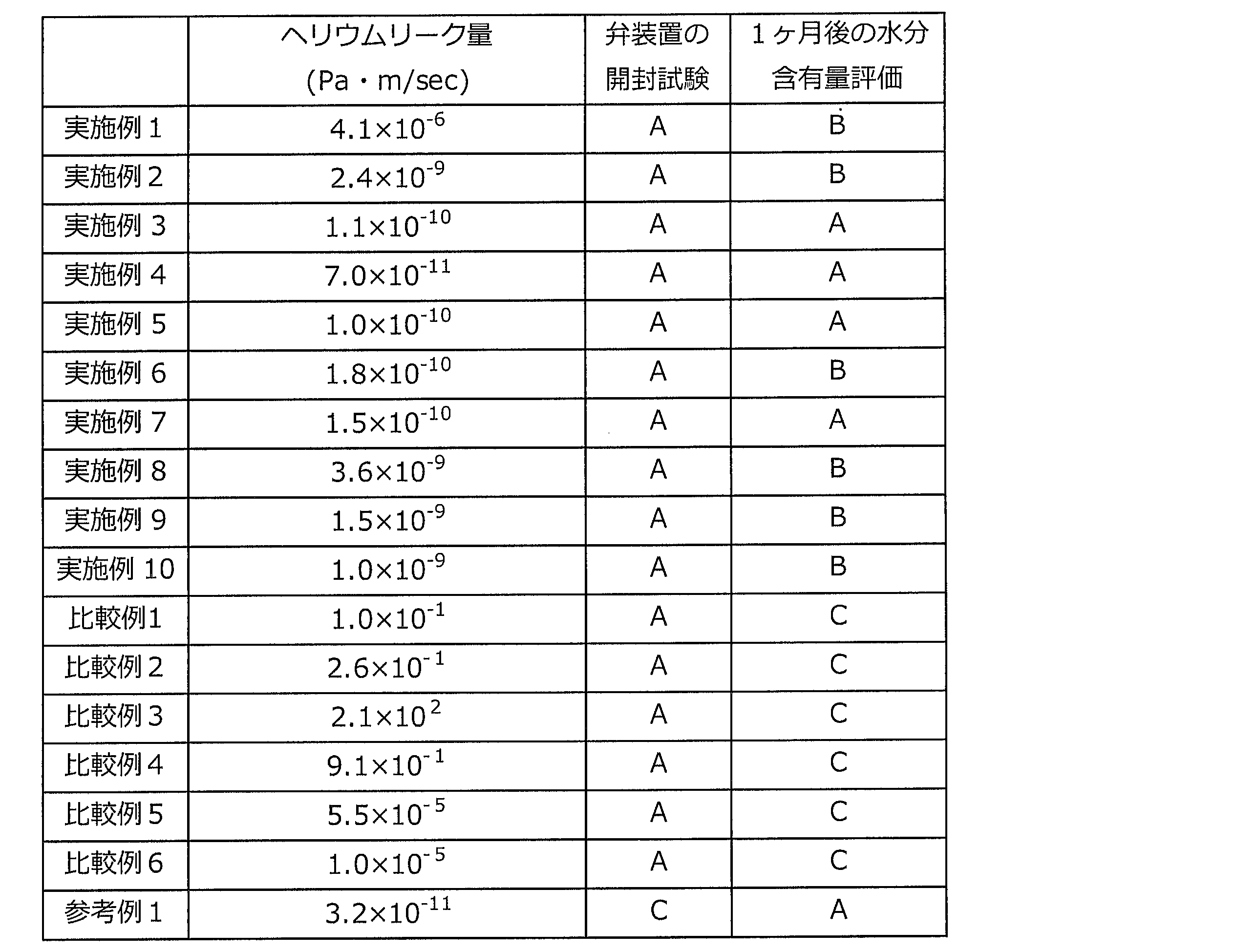
弁装置の二次側から一次側へのヘリウムリーク量が5.0×10⁻¹¹Pa・m3/sec以上、5.0×10-6Pa・m3/sec以下である実施例1~10の蓄電デバイス用弁装置を用いることにより、蓄電デバイスの内部でガスが発生した場合には、当該ガスを外部に放出することができ、かつ、外部環境からの水分の侵入を高度に抑制することができた。特に、ヘリウムリーク量が5.0×10-11Pa・m3/secから1.5×10-10Pa・m3/secである実施例3~5,7の蓄電デバイス用弁装置を用いた場合には、ガスを外部に放出しつつ、外部環境からの水分の侵入をより一層高度に抑制することができた。
以上の通り、本開示は、下記に掲げる態様の発明を提供する。
項1. 蓄電デバイス素子と、前記蓄電デバイス素子を内部に収容する収容体とを備える蓄電デバイスの前記収容体に取り付けられる蓄電デバイス用弁装置であって、
前記弁装置は、前記収容体の内部において発生したガスに起因して前記収容体の内部の圧力が上昇した場合に該圧力を低下させるように構成されており、
前記弁装置は、25℃環境において、JIS Z2331:2006「ヘリウム漏れ試験方法」の「真空吹付け法(スプレー法)」に規定された方法に準拠して測定される、前記弁装置の二次側から一次側へのヘリウムリーク量が5.0×10⁻¹¹Pa・m3/sec以上、5.0×10-6Pa・m3/sec以下である、蓄電デバイス用弁装置。
項2. 前記収容体が、少なくとも、基材層、バリア層及び熱融着性樹脂層をこの順に有する積層体によって構成されている、項1に記載の蓄電デバイス用弁装置。
項3. 前記弁装置の一次側と二次側の差圧が0.05~1MPaの範囲内で、前記弁装置が開放されるように設定されている、項1または項2に記載の蓄電デバイス用弁装置。項4. 前記弁装置は、前記収容体の内部において発生したガスに起因して前記収容体の内部の圧力が上昇した場合に該圧力を低下させる弁機構が内部に形成された第1部分と、
前記収容体の内部において発生したガスを前記弁機構へ誘導する通気路が内部に形成された第2部分とを含む、項1~3のいずれか1項に記載の蓄電デバイス用弁装置。
項5. 前記蓄電デバイスの厚み方向において、前記第1部分の長さは前記第2部分の長さよりも長く、
前記第1部分と前記第2部分との境界には段差が形成されている、項4に記載の蓄電デバイス用弁装置。
項6. 前記蓄電デバイスの幅方向における前記第2部分の長さは、前記蓄電デバイスの厚み方向における前記第2部分の長さよりも長い、項4又は5に記載の蓄電デバイス用弁装置。
項7. 前記第2部分は、前記収容体の幅方向の端部に近づくほど薄く形成された翼状延端部を有する、項4~6のいずれか1項に記載の蓄電デバイス用弁装置。
項8. 前記通気路の断面形状は円形である、項4~7のいずれか1項に記載の蓄電デバイス用弁装置。
項9. 前記収容体の幅方向における前記通気路の断面の長さは、前記蓄電デバイスの厚み方向における前記通気路の断面の長さよりも長い、項4~8のいずれか1項に記載の蓄電デバイス用弁装置。
項10. 前記第2部分は、前記通気路内に形成されたピラーを有する、項4~9のいずれか1項に記載の蓄電デバイス用弁装置。
項11. 前記第2部分の外表面はナシ地である、項4~10のいずれか1項に記載の蓄電デバイス用弁装置。
項12. 前記第2部分の外表面には、周方向に延びる凸条部が少なくとも1つ形成されている、項4~11のいずれか1項に記載の蓄電デバイス用弁装置。
項13. 前記第2部分において、前記第1部分側とは反対側の端部の平面視における角が丸みを帯びている、項4~12のいずれか1項に記載の蓄電デバイス用弁装置。
項14. 前記通気路の中心線を法線とする前記第2部分の断面の外形が多角形であり、
前記多角形の角が丸みを帯びている、項4~13のいずれか1項に記載の蓄電デバイス用弁装置。
項15. 前記第1部分及び前記第2部分の各々は異なる材料で構成されており、
前記第1部分の材料の融点は、前記第2部分の材料の融点よりも高い、項4~14のいずれか1項に記載の蓄電デバイス用弁装置。
項16. 前記第1部分及び前記第2部分の少なくとも一方の外表面の少なくとも一部に平面が形成されている、項4~15のいずれか1項に記載の蓄電デバイス用弁装置。
項17. 蓄電デバイス素子と、
前記蓄電デバイス素子を内部に収容する収容体と、
前記収容体の内部と連通する弁装置とを備え、
前記弁装置は、前記収容体の内部において発生したガスに起因して前記収容体の内部の圧力が上昇した場合に該圧力を低下させるように構成されており、
前記弁装置は、25℃環境において、JIS Z2331:2006「ヘリウム漏れ試験方法」の「真空吹付け法(スプレー法)」に規定された方法に準拠して測定される、前記弁装置の二次側から一次側へのヘリウムリーク量が5.0×10⁻¹¹Pa・m3/sec以上、5.0×10-6Pa・m3/sec以下である、蓄電デバイス。
10 蓄電デバイス、31 基材層、32 接着剤層、33 バリア層、34 接着層、35 熱融着性樹脂層、40,40I,41,41I 翼状延端部、50,51 ピラー、60 凸条部、100 収容体、110,110K,120 包装材料、112 成形部、114,114K フランジ部、116K 弁装置配置部、130 周縁接合部、200,200A、200B,200C,200D,200E,200F,200G,200H,200I,200J 弁装置、210,210A、210B,210C,210E,210F,210G,210H,210I,210J 弁機能部、212 弁座、214 ボール、216 バネ、218 メンブレン、220,220A、220B,220C,220D,220E,220F,220G,220H,220I,220J シール取付け部、300 タブ、310 タブフィルム、400 蓄電デバイス素子、A1,A2,A3,A4,A5,A6,A7 通気路、C1 中心線、O1 排気口。
Claims (15)
- 蓄電デバイス素子と、前記蓄電デバイス素子を内部に収容する収容体とを備える蓄電デバイスの前記収容体に取り付けられる蓄電デバイス用弁装置であって、
前記弁装置は、前記収容体の内部において発生したガスに起因して前記収容体の内部の圧力が上昇した場合に該圧力を低下させるように構成されており、
前記弁装置は、前記収容体の内部において発生したガスに起因して前記収容体の内部の圧力が上昇した場合に該圧力を低下させる弁機構が内部に形成された第1部分と、
前記収容体の内部において発生したガスを前記弁機構へ誘導する通気路が内部に形成された第2部分とを含み、
前記第2部分は、前記収容体の厚み方向に直交する方向である幅方向の端部に近づくほど薄く形成された翼状延端部を有し、
前記弁装置は、25℃環境において、JIS Z2331:2006「ヘリウム漏れ試験方法」の「真空吹付け法(スプレー法)」に規定された方法に準拠して測定される、前記弁装置の二次側から一次側へのヘリウムリーク量が5.0×10⁻¹¹Pa・m3/sec以上、5.0×10-6Pa・m3/sec以下である、蓄電デバイス用弁装置。 - 前記収容体が、少なくとも、基材層、バリア層及び熱融着性樹脂層をこの順に有する積層体によって構成されている、請求項1に記載の蓄電デバイス用弁装置。
- 前記弁装置の一次側と二次側の差圧が0.05~1MPaの範囲内で、前記弁装置が開放されるように設定されている、請求項1または請求項2に記載の蓄電デバイス用弁装置。
- 前記蓄電デバイスの厚み方向において、前記第1部分の長さは前記第2部分の長さよりも長く、
前記第1部分と前記第2部分との境界には段差が形成されている、請求項3に記載の蓄電デバイス用弁装置。 - 前記蓄電デバイスの厚み方向に直交する方向である幅方向における前記第2部分の長さは、前記蓄電デバイスの厚み方向における前記第2部分の長さよりも長い、請求項3又は4に記載の蓄電デバイス用弁装置。
- 前記通気路の断面形状は円形である、請求項3~5のいずれか1項に記載の蓄電デバイス用弁装置。
- 前記収容体の厚み方向に直交する方向である幅方向における前記通気路の断面の長さは、前記蓄電デバイスの厚み方向における前記通気路の断面の長さよりも長い、請求項3~6のいずれか1項に記載の蓄電デバイス用弁装置。
- 前記第2部分は、前記通気路内に形成されたピラーを有する、請求項3~7のいずれか1項に記載の蓄電デバイス用弁装置。
- 前記第2部分の外表面は梨地である、請求項3~8のいずれか1項に記載の蓄電デバイス用弁装置。
- 前記第2部分の外表面には、周方向に延びる凸条部が少なくとも1つ形成されている、請求項3~9のいずれか1項に記載の蓄電デバイス用弁装置。
- 前記第2部分において、前記第1部分側とは反対側の端部の平面視における角が丸みを帯びている、請求項3~10のいずれか1項に記載の蓄電デバイス用弁装置。
- 前記通気路の中心線を法線とする前記第2部分の断面の外形が多角形であり、
前記多角形の角が丸みを帯びている、請求項3~11のいずれか1項に記載の蓄電デバイス用弁装置。 - 前記第1部分及び前記第2部分の各々は異なる材料で構成されており、
前記第1部分の材料の融点は、前記第2部分の材料の融点よりも高い、請求項3~12のいずれか1項に記載の蓄電デバイス用弁装置。 - 前記第1部分及び前記第2部分の少なくとも一方の外表面の少なくとも一部に平面が形成されている、請求項3~13のいずれか1項に記載の蓄電デバイス用弁装置。
- 蓄電デバイス素子と、
前記蓄電デバイス素子を内部に収容する収容体と、
前記収容体の内部と連通する弁装置とを備え、
前記弁装置は、前記収容体の内部において発生したガスに起因して前記収容体の内部の圧力が上昇した場合に該圧力を低下させるように構成されており、
前記弁装置は、前記収容体の内部において発生したガスに起因して前記収容体の内部の圧力が上昇した場合に該圧力を低下させる弁機構が内部に形成された第1部分と、
前記収容体の内部において発生したガスを前記弁機構へ誘導する通気路が内部に形成された第2部分とを含み、
前記第2部分は、前記収容体の厚み方向に直交する方向である幅方向の端部に近づくほど薄く形成された翼状延端部を有し、
前記弁装置は、25℃環境において、JIS Z2331:2006「ヘリウム漏れ試験方法」の「真空吹付け法(スプレー法)」に規定された方法に準拠して測定される、前記弁装置の二次側から一次側へのヘリウムリーク量が5.0×10⁻¹¹Pa・m3/sec以上、5.0×10-6Pa・m3/sec以下である、蓄電デバイス。
Priority Applications (4)
| Application Number | Priority Date | Filing Date | Title |
|---|---|---|---|
| US17/280,106 US20220006155A1 (en) | 2018-09-25 | 2019-09-25 | Valve device for power storage device and power storage device |
| KR1020217006872A KR20210058828A (ko) | 2018-09-25 | 2019-09-25 | 축전 디바이스용 밸브 장치 및 축전 디바이스 |
| CN201980063020.4A CN112753122B (zh) | 2018-09-25 | 2019-09-25 | 蓄电器件用阀装置和蓄电器件 |
| EP19864300.9A EP3859819A4 (en) | 2018-09-25 | 2019-09-25 | VALVE DEVICE FOR POWER STORAGE DEVICE AND POWER STORAGE DEVICE |
Applications Claiming Priority (2)
| Application Number | Priority Date | Filing Date | Title |
|---|---|---|---|
| JP2018-179525 | 2018-09-25 | ||
| JP2018179525A JP7205136B2 (ja) | 2018-09-25 | 2018-09-25 | 蓄電デバイス用弁装置及び蓄電デバイス |
Publications (1)
| Publication Number | Publication Date |
|---|---|
| WO2020067130A1 true WO2020067130A1 (ja) | 2020-04-02 |
Family
ID=69951860
Family Applications (1)
| Application Number | Title | Priority Date | Filing Date |
|---|---|---|---|
| PCT/JP2019/037534 WO2020067130A1 (ja) | 2018-09-25 | 2019-09-25 | 蓄電デバイス用弁装置及び蓄電デバイス |
Country Status (6)
| Country | Link |
|---|---|
| US (1) | US20220006155A1 (ja) |
| EP (1) | EP3859819A4 (ja) |
| JP (1) | JP7205136B2 (ja) |
| KR (1) | KR20210058828A (ja) |
| CN (1) | CN112753122B (ja) |
| WO (1) | WO2020067130A1 (ja) |
Families Citing this family (2)
| Publication number | Priority date | Publication date | Assignee | Title |
|---|---|---|---|---|
| US11349166B2 (en) * | 2018-06-28 | 2022-05-31 | Luis Perez | Fire suppressant enclosures for battery cell systems and associated methods of modular operation |
| US11824220B2 (en) * | 2020-09-03 | 2023-11-21 | Apple Inc. | Electronic device having a vented battery barrier |
Citations (6)
| Publication number | Priority date | Publication date | Assignee | Title |
|---|---|---|---|---|
| JPH04328241A (ja) * | 1991-04-30 | 1992-11-17 | Fuji Photo Film Co Ltd | 密閉型非水電池の安全弁 |
| JP2006179442A (ja) * | 2004-11-25 | 2006-07-06 | Nec Lamilion Energy Ltd | フィルム外装電気デバイスおよびフィルム外装電気デバイス集合体 |
| WO2009001947A1 (ja) * | 2007-06-22 | 2008-12-31 | Rubycon Corporation | 電子部品用圧力調節弁及びこれを用いた電子部品 |
| JP2011155139A (ja) | 2010-01-27 | 2011-08-11 | Power System:Kk | キャパシタバルブ及びそれを用いた電気二重層キャパシタセル |
| WO2013146803A1 (ja) * | 2012-03-28 | 2013-10-03 | 株式会社オプトニクス精密 | 安全弁および電気化学素子 |
| JP2016152231A (ja) * | 2015-02-16 | 2016-08-22 | 有量科技股▲ふん▼有限公司 | リチウム電池の排気構造 |
Family Cites Families (14)
| Publication number | Priority date | Publication date | Assignee | Title |
|---|---|---|---|---|
| JPH02199768A (ja) * | 1989-01-27 | 1990-08-08 | Hitachi Maxell Ltd | 密閉型アルカリ蓄電池 |
| US5386717A (en) * | 1991-02-08 | 1995-02-07 | Yamaha Corporation | Gas leakage testing method |
| JP3201667B2 (ja) * | 1993-02-10 | 2001-08-27 | 清原 まさ子 | 逆止弁用試験装置及び逆止弁の試験方法 |
| JPH11250887A (ja) * | 1998-02-28 | 1999-09-17 | Toyota Central Res & Dev Lab Inc | 電池の放圧構造 |
| US7150936B2 (en) * | 2000-10-25 | 2006-12-19 | Nec Tokin Tochigi, Ltd. | Sealed battery and method for manufacturing sealed battery |
| JP2003045395A (ja) * | 2001-07-30 | 2003-02-14 | Sanyo Electric Co Ltd | 密閉型蓄電池 |
| KR101182821B1 (ko) * | 2010-08-05 | 2012-09-13 | 대우기공 주식회사 | 누설 검사 장치 및 방법 |
| FR2980306B1 (fr) * | 2011-09-15 | 2013-10-11 | Commissariat Energie Atomique | Procede de test d'etancheite d'une structure bipolaire pour generateur electrochimique |
| JP5210450B1 (ja) * | 2012-11-07 | 2013-06-12 | 直芳 可知 | 燃料電池および燃料電池システム |
| JP5747937B2 (ja) * | 2013-04-19 | 2015-07-15 | トヨタ自動車株式会社 | 密閉型電池の製造方法 |
| JP5679367B2 (ja) * | 2013-06-19 | 2015-03-04 | 三菱自動車工業株式会社 | バッテリーボックス気密検査装置 |
| JP6631142B2 (ja) * | 2015-10-05 | 2020-01-15 | 日産自動車株式会社 | 検査方法及び検査装置 |
| JP6699590B2 (ja) * | 2017-02-23 | 2020-05-27 | トヨタ自動車株式会社 | 非水系二次電池 |
| JP6895373B2 (ja) * | 2017-12-19 | 2021-06-30 | 日立Astemo株式会社 | 自動車用電子制御装置 |
-
2018
- 2018-09-25 JP JP2018179525A patent/JP7205136B2/ja active Active
-
2019
- 2019-09-25 EP EP19864300.9A patent/EP3859819A4/en active Pending
- 2019-09-25 WO PCT/JP2019/037534 patent/WO2020067130A1/ja unknown
- 2019-09-25 CN CN201980063020.4A patent/CN112753122B/zh active Active
- 2019-09-25 KR KR1020217006872A patent/KR20210058828A/ko active Search and Examination
- 2019-09-25 US US17/280,106 patent/US20220006155A1/en active Pending
Patent Citations (6)
| Publication number | Priority date | Publication date | Assignee | Title |
|---|---|---|---|---|
| JPH04328241A (ja) * | 1991-04-30 | 1992-11-17 | Fuji Photo Film Co Ltd | 密閉型非水電池の安全弁 |
| JP2006179442A (ja) * | 2004-11-25 | 2006-07-06 | Nec Lamilion Energy Ltd | フィルム外装電気デバイスおよびフィルム外装電気デバイス集合体 |
| WO2009001947A1 (ja) * | 2007-06-22 | 2008-12-31 | Rubycon Corporation | 電子部品用圧力調節弁及びこれを用いた電子部品 |
| JP2011155139A (ja) | 2010-01-27 | 2011-08-11 | Power System:Kk | キャパシタバルブ及びそれを用いた電気二重層キャパシタセル |
| WO2013146803A1 (ja) * | 2012-03-28 | 2013-10-03 | 株式会社オプトニクス精密 | 安全弁および電気化学素子 |
| JP2016152231A (ja) * | 2015-02-16 | 2016-08-22 | 有量科技股▲ふん▼有限公司 | リチウム電池の排気構造 |
Non-Patent Citations (1)
| Title |
|---|
| See also references of EP3859819A4 |
Also Published As
| Publication number | Publication date |
|---|---|
| KR20210058828A (ko) | 2021-05-24 |
| CN112753122B (zh) | 2023-11-17 |
| CN112753122A (zh) | 2021-05-04 |
| JP2020053179A (ja) | 2020-04-02 |
| US20220006155A1 (en) | 2022-01-06 |
| JP7205136B2 (ja) | 2023-01-17 |
| EP3859819A4 (en) | 2022-06-22 |
| EP3859819A1 (en) | 2021-08-04 |
Similar Documents
| Publication | Publication Date | Title |
|---|---|---|
| JP6540871B1 (ja) | 蓄電デバイス用弁装置及び蓄電デバイス | |
| CN112236897B (zh) | 电池 | |
| CN112272890B (zh) | 电池、热封装置和电池的制造方法 | |
| JP2024045178A (ja) | 蓄電デバイス用弁装置及び蓄電デバイス | |
| WO2020067130A1 (ja) | 蓄電デバイス用弁装置及び蓄電デバイス | |
| JP6604414B1 (ja) | 蓄電デバイス | |
| CN112272889B (zh) | 电池 | |
| JP6530850B1 (ja) | 電池 | |
| WO2020067131A1 (ja) | 蓄電デバイス | |
| CN112272883B (zh) | 电池 | |
| JP6530847B1 (ja) | 電池 | |
| JP6530849B1 (ja) | 電池 | |
| JP6530848B1 (ja) | 電池、ヒートシール装置、及び電池の製造方法 | |
| JP7187927B2 (ja) | 蓄電デバイス |
Legal Events
| Date | Code | Title | Description |
|---|---|---|---|
| 121 | Ep: the epo has been informed by wipo that ep was designated in this application |
Ref document number: 19864300 Country of ref document: EP Kind code of ref document: A1 |
|
| NENP | Non-entry into the national phase |
Ref country code: DE |
|
| ENP | Entry into the national phase |
Ref document number: 2019864300 Country of ref document: EP Effective date: 20210426 |