WO2020066500A1 - ドライヤー - Google Patents
ドライヤー Download PDFInfo
- Publication number
- WO2020066500A1 WO2020066500A1 PCT/JP2019/034669 JP2019034669W WO2020066500A1 WO 2020066500 A1 WO2020066500 A1 WO 2020066500A1 JP 2019034669 W JP2019034669 W JP 2019034669W WO 2020066500 A1 WO2020066500 A1 WO 2020066500A1
- Authority
- WO
- WIPO (PCT)
- Prior art keywords
- reflector
- light
- filter
- dryer according
- dryer
- Prior art date
- Legal status (The legal status is an assumption and is not a legal conclusion. Google has not performed a legal analysis and makes no representation as to the accuracy of the status listed.)
- Ceased
Links
Images


Classifications
-
- A—HUMAN NECESSITIES
- A45—HAND OR TRAVELLING ARTICLES
- A45D—HAIRDRESSING OR SHAVING EQUIPMENT; EQUIPMENT FOR COSMETICS OR COSMETIC TREATMENTS, e.g. FOR MANICURING OR PEDICURING
- A45D20/00—Hair drying devices; Accessories therefor
- A45D20/04—Hot-air producers
- A45D20/08—Hot-air producers heated electrically
- A45D20/10—Hand-held drying devices, e.g. air douches
-
- F—MECHANICAL ENGINEERING; LIGHTING; HEATING; WEAPONS; BLASTING
- F26—DRYING
- F26B—DRYING SOLID MATERIALS OR OBJECTS BY REMOVING LIQUID THEREFROM
- F26B21/00—Arrangements for supplying or controlling air or other gases for drying solid materials or objects
-
- F—MECHANICAL ENGINEERING; LIGHTING; HEATING; WEAPONS; BLASTING
- F26—DRYING
- F26B—DRYING SOLID MATERIALS OR OBJECTS BY REMOVING LIQUID THEREFROM
- F26B3/00—Drying solid materials or objects by processes involving the application of heat
- F26B3/28—Drying solid materials or objects by processes involving the application of heat by radiation, e.g. from the sun
- F26B3/30—Drying solid materials or objects by processes involving the application of heat by radiation, e.g. from the sun from infrared-emitting elements
Definitions
- the present invention relates to a dryer for drying hair and the like using infrared rays.
- Patent Document 1 ⁇ ⁇ ⁇ ⁇ ⁇ ⁇ ⁇ This type of dryer is disclosed in Patent Document 1, for example.
- the dryer described in Patent Literature 1 includes a fan (blowing fan), a hot-wire light source (light-emitting body), and a reflector (reflector) that surrounds the hot-wire light source inside a cylindrical main body (main body case). And a filter (optical filter) for closing the opening surface of the reflector.
- the heat ray light source includes a halogen lamp, an incandescent lamp, a xenon lamp, a metal halide lamp, and the like. By providing a filter on the opening surface of the reflector, most of the visible light among the light (electromagnetic waves) emitted from the hot-wire light source can be blocked, and the infrared light for heating the hair can be transmitted.
- An object of the present invention is to provide a dryer that reliably prevents light leaked out of a reflector from being emitted from an air outlet and does not make a user feel dazzling when drying hair. .
- the dryer according to the present invention includes a blower fan 3 for supplying dry air to an air outlet 11, a luminous body 28 serving as a heating source, and a luminous body 28 inside a ventilation path 9 formed in the main body case 1. And a reflector 29 that reflects and guides light emitted from the light source toward the outlet 11. In the light irradiation path between the reflector 29 and the air outlet 11, a filter 30 that blocks transmission of visible light out of the light emitted from the light emitter 28 is arranged.
- a first vent 48 is opened at a rear portion of the reflector 29, and a second vent 42 is opened at a front portion of the reflector 29.
- the reflector 29 is formed through the first vent 48 and the second vent 42. The inside is ventilated.
- an antiglare body 75 that blocks light leaking from the second vent 42 is provided on the outer surface of the second vent 42.
- the term “filter that blocks transmission of visible light” includes a filter that allows a part of visible light to pass while attenuating visible light.
- the anti-glare body 75 is formed in a cylindrical shape that covers the outer surface of the opening of the second ventilation port 42, and the rear end of the cylinder wall of the anti-glare body 75 projects rearward from the rear opening edge of the second ventilation port 42. .
- the second ventilation port 42 is formed in a circular shape at the front of the reflector 29, and the outer surface of the opening of the second ventilation port 42 is covered with a cylindrical anti-glare body 75.
- the reflector 29 is formed by joining the front reflector 37 and the rear reflector 38, and the filter 30 is disposed at the front of the front reflector 37 and is fixed to the front reflector 37 by the filter support structure 59.
- Reference numeral 59 denotes a filter receiving seat 41 formed on the inner surface of the front end of the front reflector 37, and a press ring 60 which is externally fitted and fixed on the front peripheral surface of the front reflector 37 and cooperates with the filter receiving seat 41 to clamp and fix the filter 30.
- a ring-shaped anti-glare body 75 is formed integrally with the holding ring 60.
- the dry air sent from the blower fan 3 is introduced into the interior of the reflector 29 from the first vent 48 and is sent out from the second vent 42, and the anti-glare body 75 and the second vent
- a ventilation passage 76 that allows the passage of dry air is formed between the second ventilation hole 42 and the L-shaped reclined side, and the front end of the ventilation passage 76 contacts the inner surface of the anti-glare body 75.
- a rear reversing guide surface 78 for reversing and guiding the drying air backward is formed in an inner corner portion which is closed by the corresponding passage end wall 77 and is sandwiched between the anti-glare body 75 and the passage end wall 77.
- a front reversing guide surface 79 is formed at the rear end of the anti-glare body 75 to reversibly guide the dry air flowing out of the ventilation passage 76 forward.
- the front reflector 37 is formed by joining a pair of divided half bodies 37a and 37b, and the antiglare body 75 and the filter support structure 59 are formed integrally with the pair of half bodies 37a and 37b. Have been.
- a narrowing portion 104 for reducing the passage cross-sectional area of the air guide passage 9 surrounding the periphery of the front reflector 37 is formed to bulge.
- the outer surface of the diaphragm 104 is flush with the virtual outer surface passing through the peripheral surface of the anti-glare body 75 or is located inside the virtual outer surface.
- the front end face 105 of the throttle portion 104 facing the air guide passage 9 and continuing to the peripheral surface of the front reflector 37 is inclined backward by a predetermined angle ⁇ with respect to the center axis P of the main body case 1.
- a negative pressure forming structure 106 for reducing the passage cross-sectional area of the air guide path 9 surrounding the periphery of the front reversing guide surface 79 is provided. .
- the negative pressure forming structure 106 is formed of a porous body, and the cosmetic component is impregnated and held in the negative pressure forming structure 106.
- the negative pressure forming structure 106 is formed by a throttle ring 112 having a throttle surface 107 on the inner surface, and is fixed to the wind guide cylinder 7 surrounding the circumference of the wind guide path 9.
- the negative pressure forming structure 106 is composed of a Venturi cylinder 108 having an inner cylinder 109 and an outer cylinder 110 which are double inner and outer, and the outer cylinder 110 is fixed to the wind guide cylinder 7 surrounding the periphery of the wind guide path 9. .
- a front narrowing ring-shaped throttle passage 111 is formed between the inner cylinder 109 and the outer cylinder 110.
- the front reflector 37 is formed of a metal material, and the filter seat 41 formed on the inner surface of the front end of the front reflector 37 is in close contact with the peripheral surface and the rear peripheral edge of the filter 30.
- the dry air sent from the blower fan 3 is introduced into the interior of the reflector 29 from the second vent 42 and is sent out from the first vent 48, and the anti-glare body 75 surrounding the outer surface of the second vent 42. However, it also serves as a wind guide 115 that guides the dry air flowing around the reflector 29 to the second ventilation port 42 in reverse.
- the first ventilation port 48 is formed in a ring shape so as to surround the luminous body 28, and a baffle plate 116 that covers the entire first ventilation port 48 is arranged on the rear outer surface of the first ventilation port 48. . It is possible to adopt a configuration in which a part of the drying air supplied from the blowing fan 3 is prevented from flowing into the interior of the reflector 29 from the first ventilation port 48 by the baffle plate 116.
- the reflector 29 is configured by joining the front reflector 37 and the rear reflector 38, and the front engagement portion 51 that engages and recesses with the joining surface of the front reflector 37 and the rear reflector 38 to restrict the slipping movement of the joining partner. And a rear engagement portion 54 are formed.
- a screw 56 inserted into one of the front engagement portion 51 and the rear engagement portion 54 is screwed into a screw boss 55 provided on the other, so that the front reflector 37 and the rear reflector 38 are fixed inseparably.
- the front reflector 37 is formed by joining a pair of divided half bodies 37a and 37b, and the joining surface of the rear reflector 38 includes a joining groove 52 for fitting and supporting the rear edge of the front reflector 37.
- a joining wall 53 for supporting a rear edge peripheral surface of the front reflector 37 is formed, and a concave rear engaging portion 54 formed by notching the joining wall 53 and a screw boss 55 are formed at a plurality of portions of the joining wall 53.
- the screw 56 inserted into the front engagement portion 51 is screwed into the screw boss 55 of the rear engagement portion 54.
- the front reflector 37 and the rear reflector 38 are integrated. It is possible to take.
- the filter 30 is disposed at the front of the front reflector 37 and is fixed to the front reflector 37 by a filter support structure 59.
- the filter support structure 59 includes a filter seat 41 formed on the inner surface of the front end of the front reflector 37, There is provided a press ring 60 which is externally fitted and fixed to the front peripheral surface of the reflector 37 and cooperates with the filter receiving seat 41 to hold and fix the filter 30.
- a light source support structure for supporting the light emitter 28 is provided at a rear portion of the reflector 29.
- the light source support structure includes a light source stand 45 for supporting the light emitter 28, and a cylinder surrounding the light source stand 45 and having an open rear end. And a wind guide wall 46 in a shape of a circle.
- the socket 34 for the light emitting body 28 is fastened and fixed to the light source base 45 by a plurality of screws 47, and the plug 33 of the light emitting body 28 is inserted and mounted in the socket 34.
- the luminous body 28, the reflector 29, and the filter 30 are unitized as one heat source unit 4, and a ring-shaped spring receiving frame that supports the heat source unit 4 is provided on the wind guide tube 7 surrounding the wind guide path 9.
- the shock absorbing spring 65 that supports the heat source unit 4 is disposed at a plurality of positions on the opposing surface of the reflector 29 and the spring receiving frame 64, and the heat source unit 4 is floatingly supported on the main body case 1. I have.
- the reflector 29 has a first reflecting surface 39 for guiding the light emitted from the illuminant 28 toward the filter 30 in a forward direction, and is disposed adjacent to the first reflecting surface 39 so that the light emitted from the illuminant 28 is
- a second reflecting surface 40 that reflects and guides backward, and a light that is disposed adjacent to the second reflecting surface 40 and that is radiated from the light emitter 28 and light that is reflected and guided by the second reflecting surface 40 is directed toward the filter 30.
- a third reflecting surface 43 for guiding reflection forward is provided, and a light emitting portion of the light emitting body 28 which is long in front and rear faces a portion adjacent to the second reflecting surface 40 and the third reflecting surface 43.
- the front-rear dimension of the reflector 29 including the first reflection surface 39, the second reflection surface 40, and the third reflection surface 43 is set to be larger than the radial dimension of the reflector 29.
- a filter 30 is disposed in a front opening of the reflector 29.
- the blower fan 3, the light-emitting body 28, and the reflector 29 are arranged inside the air guide path 9, and a filter for blocking transmission of visible light is provided in a light irradiation path between the reflector 29 and the outlet 11. 30 were placed.
- an anti-glare body 75 is provided on the outer surface of the second ventilation port 42 formed at the front part of the reflector 29, and the light leaking from the second ventilation port 42 together with the drying air is shielded by the anti-glare body 75. .
- the light leaking from the second ventilation port 42 is shielded by the anti-glare body 75 while the inside of the reflector 29 is ventilated and cooled by the drying air introduced into the inside of the reflector 29, and the light is guided. Irradiation toward the outlet 11 along the air path 9 can be prevented. Specifically, the light leaked from the second vent 42 is reflected by the anti-glare 75 toward the second vent 42 or scattered by the anti-glare 75, and Can be absorbed and attenuated. Therefore, it is possible to provide a dryer that can prevent the light leaking out of the reflector 29 from being emitted from the air outlet 11 and irradiating the user with dazzling light when drying the hair.
- the anti-glare body 75 When the anti-glare body 75 is formed in a cylindrical shape, and the rear end of the cylindrical wall of the anti-glare body 75 projects rearward from the rear opening edge of the second ventilation port 42, the rear end edge of the second ventilation port 42 Light radiated in the radial direction and light radiated diagonally forward can be reliably blocked by the inner surface of the cylindrical wall of the antiglare body 75. A part of the light is applied to the air guide path 9 through the space between the anti-glare body 75 and the peripheral surface of the reflector 29, and the rear end of the cylindrical wall of the anti-glare body 75 is Since the light is located behind the rear opening edge, all the light applied to the air guide path 9 is repeatedly reflected in a state inclined backward. Therefore, it is possible to more reliably prevent the light in the air guide path 9 from being irradiated toward the outlet 11.
- the drying air can enter and exit the second vent 42 smoothly. Therefore, the luminous body 28 and the reflector 29 can be effectively cooled by the dry air introduced into the interior of the reflector 29.
- the reflector 29 is constituted by the front reflector 37 and the rear reflector 38, and the filter 30 disposed in front of the front reflector 37 is fixed by the filter support structure 59. Further, the filter support structure 59 is provided with a filter seat 41 formed on the front reflector 37 and a pressing ring 60 for holding and fixing the filter 30 in cooperation with the receiver seat 41. According to such a dryer, the filter 30 is assembled to the filter receiver 41, and the holding ring 60 is externally fitted and fixed to the front peripheral surface of the front reflector 37, whereby the filter 30 is easily assembled to the front reflector 37, It can be firmly fixed inseparably.
- the ring-shaped anti-glare body 75 is formed integrally with the holding ring 60 using the holding ring 60. According to such a dryer, compared to the case where the anti-glare body 75 is provided separately from the press ring 60, the number of parts can be reduced by the use of the press ring 60 and the manufacturing cost of the dryer can be reduced.
- the dry air supplied from the blower fan 3 is introduced into the interior of the reflector 29 from the first vent 48 and is sent out from the second vent 42.
- the direction of the flow of the dry air inside the reflector 29 and the direction of the flow of the dry air supplied from the blower fan 3 in the air guide path 9 can be made to coincide with each other.
- the part can be reliably introduced into the interior of the reflector 29, so that the light emitter 28 and the reflector 29 can be cooled properly.
- a ventilation passage 76 is formed between the anti-glare body 75 and the second ventilation port 42, and the drying wind is directed backward to the inner corner portion between the passage end wall 77 at the front end of the passage 76 and the anti-glare body 75.
- the reverse guide surface 78 is formed. As described above, when the rear inversion guide surface 78 is formed at the inner corner portion between the anti-glare body 75 and the passage end wall 77, the dry wind after passing through the second ventilation port 42 is subjected to the rear inversion guide surface 78. Thus, the air passage 76 can be smoothly guided to the rear opening toward the rear opening. Accordingly, the flow of the drying air in the ventilation passage 76 is made to be an orderly flow, and a part of the drying air after cooling the light emitter 28 and the reflector 29 is prevented from staying in the second ventilation port 42 and the ventilation passage 76. be able to.
- the dry air flowing out of the ventilation passage 76 is The air can be smoothly inverted and guided toward the outer surface side to join the dry air flowing in the air guide path 9.
- the front reflector 37 is formed by joining the pair of divided half bodies 37a and 37b, and the anti-glare body 75 and the filter support structure 59 are formed integrally with the pair of half bodies 37a and 37b. .
- the filter 30 can be integrated with the front reflector 37 by joining and fixing the pair of half bodies 37a and 37b.
- the number of parts can be reduced by the amount that the anti-glare member 75 and the filter support structure 59 are formed integrally with the pair of half bodies 37a and 37b, thereby reducing the manufacturing cost of the dryer.
- the passage cross-sectional area of the air guide 9 surrounding the front reflector 37 is reduced by the amount of the throttle 104.
- the drying air can be fed toward the outlet 11 in a state where the flow velocity of the drying air passing through the restricting portion 104 is increased. Accordingly, the periphery of the drying air discharged from the ventilation passage 76 is surrounded by the flow of the drying air having the high flow velocity, so that the drying air having passed through the ventilation passage 76 is surely combined with the drying air having the high flow velocity. , And can be smoothly fed toward the outlet 11.
- the outer surface of the diaphragm 104 is flush with the virtual outer surface passing through the peripheral surface of the anti-glare body 75 or is located inside the virtual outer surface. According to the diaphragm 104, even if the light that has passed through the ventilation passage 76 together with the drying air may be reflected between the anti-glare body 75 and the front end wall of the diaphragm 104, the reflected light is not glare-proof. Irradiation to the peripheral surface side of the body 75 to reach the outlet 11 can be reliably prevented.
- the front end face 105 of the throttle section 104 facing the air guide passage 9 is inclined backward by a predetermined angle ⁇ with respect to the central axis P of the main body case 1.
- ⁇ the angle with respect to the central axis P of the main body case 1.
- a negative pressure forming structure 106 is provided around the front reversing guide surface 79 at the rear end of the anti-glare body 75 so as to reduce the cross-sectional area of the air guide passage 9.
- the pressure of the dry air flowing around the anti-glare body 75 can be reduced to increase the flow velocity.
- the periphery of the drying air discharged from the ventilation passage 76 is surrounded by the flow of the drying air having a high flow velocity, so that the drying air flowing from the ventilation passage 76 to the periphery of the front reversing guide surface 79 is dried. It can be surely merged by the wind and can be smoothly fed toward the outlet 11.
- the pressure of the drying air discharged from the ventilation passage 76 is higher than the pressure of the drying air flowing around the anti-glare body 75, the drying air flowing around the anti-glare body 75 flows from the ventilation passage 76 to the reflector 29. It can be prevented from getting inside.
- the negative pressure forming structure 106 made of a porous material is impregnated with a cosmetic ingredient.
- cosmetic ingredients such as collagen and vitamins are released into the dry air that comes into contact with the negative pressure forming structure 106 while flowing through the air guide passage 9, and the dry air containing the cosmetic ingredients is blown out. 11 can be sent.
- the negative pressure forming structure 106 is formed by the aperture ring 112 having the aperture surface 107 on the inner surface, and the aperture ring 112 is fixed to the wind guide cylinder 7 surrounding the air guide path 9. According to the negative pressure forming structure 106, since the drying air can be accelerated by the simple structure of the drawing ring 112, the structure of the negative pressure forming structure 106 can be simplified and the manufacturing cost of the dryer can be reduced.
- a negative pressure forming structure is formed by a Venturi cylinder 108 having an inner cylinder 109 and an outer cylinder 110 having a double inner and outer cylinder, and a front narrowing ring-shaped throttle passage 111 is formed between the inner cylinder 109 and the outer cylinder 110. I did it. According to such a negative pressure forming structure, the speed of the drying air passing through the throttle passage 111 can be remarkably increased. Further, the drying air flowing from the ventilation passage 76 to the outside of the anti-glare body 75 via the front reversing guide surface 79 can be combined by the suction effect of the high-speed drying air flowing out of the venturi tube 108. By promoting the flow of the drying air inside the reflector 37, the halogen lamp 28 and the reflector 29 can be effectively cooled by the drying air.
- a filter seat 41 is formed on the inner surface of the front end of the front reflector 37 made of a metal material, and the filter seat 41 is brought into close contact with the peripheral surface and the rear peripheral edge of the filter 30. According to such a filter support structure 59, the heat of the filter 30 is effectively conducted to the front reflector 37 side, and the cooling of the filter 30 is promoted so that the filter 30 can always be maintained at an appropriate temperature.
- baffle plate 116 that covers the entirety of the first ventilation port 48 is disposed on the rear outer surface of the first ventilation port 48 that surrounds the periphery of the light emitting body 28, a part of the dry air supplied from the ventilation fan 3
- the baffle 116 can prevent the inflow into the interior of the reflector 29 from the first vent 48. Therefore, the flow of the dry air flowing from the second ventilation port 42 to the first ventilation port 48 inside the reflector 29 is made smooth and suitable, and the luminous body 28 and the reflector 29 are cooled more effectively. Can be.
- the front reflector 37 and the rear reflector 38 are joined to form a reflector 29, and the front engagement portion 51 that engages and recesses with the joint surface between the front reflector 37 and the rear reflector 38 to restrict the slipping movement of the joining partner.
- the front reflector 51 and the rear engagement portion 54 are formed, the front engagement portion 51 and the rear engagement portion 54 are unevenly engaged with each other, thereby restricting the slipping movement of the mating partner and positioning the front reflector 37. And the rear reflector 38 can be properly assembled.
- a screw 56 inserted into one of the front engagement portion 51 and the rear engagement portion 54 is screwed into a screw boss 55 provided on the other so that the front reflector 37 and the rear reflector 38 are fixed inseparably.
- the front reflector 37 and the rear reflector 38 can be firmly fastened and fixed with the screws 56 while having a simpler fastening structure. Therefore, the optical characteristics of the reflecting surfaces 39, 40, and 43 provided on the reflector 29 can always be kept constant.
- the front reflector 37 is formed by joining a pair of half bodies 37a and 37b, and a front engagement part 51 that is engaged with the joining surface of the half bodies 37a and 37b by dropping into the rear engagement part 54 of the rear reflector 38. Is formed, the pair of half bodies 37a and 37b are joined, and the screw 56 inserted through the front engagement portion 51 is engaged with the front engagement portion 51 and the rear engagement portion 54 in a concave and convex engagement. By screwing into the screw boss 55 of the rear engaging portion 54, the front reflector 37 and the rear reflector 38 can be securely fastened and fixed. In addition, even when the shapes and structures of the front reflector 37 and the rear reflector 38 are variously changed, the three members of the half bodies 37a and 37b and the rear reflector 38 are properly integrated with each other while being positioned with respect to each other. Can be.
- the filter 30 disposed in front of the front reflector 37 is fixed by the filter support structure 59.
- the filter support structure 59 includes a filter seat 41 formed on the front reflector 37 and a press ring 60 for holding and fixing the filter 30 in cooperation with the seat 41.
- the filter 30 is assembled to the filter receiver 41, and the holding ring 60 is externally fitted and fixed to the front peripheral surface of the front reflector 37, so that the filter 30 is easily assembled to the front reflector 37.
- it can be firmly fixed inseparably.
- the light source support structure that supports the light emitter 28 includes a light source base 45 that supports the light emitter 28 and a cylindrical wind guide wall 46 that surrounds the periphery of the light source base 45.
- the light source base 45 supports the light emitter 28 and a cylindrical wind guide wall 46 that surrounds the periphery of the light source base 45.
- the light source cooling passage between the air guide wall 46 and the luminous body 28 is communicated with the first ventilation port 48, so that the dry air introduced from the rear end opening of the air guide wall 46 is The air can be effectively cooled by flowing through the one vent 48 into the interior of the reflector 29 and contacting the luminous body 28 and the reflector 29.
- the socket 34 is fastened and fixed to the light source base 45 with a plurality of screws 47, and that the light emitter 28 is supported by the light source base 45 by inserting and plugging the plug 33 of the light emitter 28 into the socket 34. did.
- the light emitter 28 and the socket 34 can be separated from the reflector 29 by loosening the screw 47 and removing the socket 34 from the light source base 45.
- the luminous body 28 can be separated from the socket 34, so that the replacement operation when the luminous body 28 breaks down can be easily performed.
- the luminous body 28, the reflector 29, and the filter 30 are unitized as one heat source unit 4. Then, a ring-shaped spring receiving frame 64 that supports the heat source unit 4 is fixed to the wind guide cylinder 7 surrounding the periphery of the air guide path 9, and the shock absorbing springs 65 are provided at a plurality of locations on the opposing surfaces of the reflector 29 and the spring receiving frame 64. Deploy. According to such a dryer, the heat source unit 4 can be supported by the plurality of shock absorbing springs 65 and can be floatingly supported on the main body case 1.
- a first reflection surface 39, a second reflection surface 40, and a third reflection surface 43 are provided inside the reflector 29, and the first reflection surface 39 emits light emitted from the light emitter 28 and reaching the first reflection surface 39. Can be reflected and guided forward toward the filter 30.
- the second reflection surface 40 enables the light emitted from the light emitter 28 and reaching the second reflection surface 40 to be reflected and guided backward.
- the third reflecting surface 43 enables the light emitted from the light emitter 28 to reach the third reflecting surface 43 and the light reflected and guided by the second reflecting surface 40 to be reflected and guided forward toward the filter 30. .
- the reflector 29 According to the reflector 29, the light emitted from the light emitter 28 and reaching each of the reflection surfaces 39, 40, and 43 is efficiently reflected and guided by each of the reflection surfaces 39, 40, and 43, and is emitted toward the filter 30. be able to. Further, since the light-emitting portion of the light-emitting body 28 which is long in the front and rear faces the adjacent portion between the second reflection surface 40 and the third reflection surface 43, it is possible to prevent the radial dimension of the reflector 29 from increasing and to make the reflector 29 compact. The light emitted from the light emitter 28 can be emitted toward the filter 30 while realizing the above. This is because, when the light emitted from the light emitting body 28 is reflected and guided by, for example, only one reflecting surface, the diameter of the irradiation opening of the reflector 29 becomes large, and the reflector 29 becomes large accordingly. Because it becomes.
- the front-rear dimension of the reflector 29 including the first reflection surface 39, the second reflection surface 40, and the third reflection surface 43 is set to be larger than the radial dimension of the reflector 29, the reflector 29 having an elongated cylindrical structure is used. , And the dryer can be made more compact because the radial dimension of the reflector 29 is smaller.
- the filter 30 When the filter 30 is disposed in the front opening of the reflector 29, it is possible to reliably prevent the unattenuated visible light from being emitted from the outlet 11, and to make the user feel dazzling when the hair is dried. We can provide a hair dryer without any.
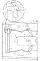
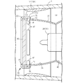
- FIG. 2 is a vertical sectional side view of the dryer according to the first embodiment.
- FIG. 2 is a vertical sectional side view showing a light emitting structure of the dryer according to the first embodiment.
- FIG. 2 is a cross-sectional plan view illustrating a light emitting structure of the dryer according to the first embodiment.
- FIG. 2 is an exploded side view illustrating a case structure of the dryer according to the first embodiment.
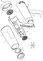
- FIG. 2 is an exploded perspective view illustrating a case structure of the dryer according to the first embodiment.
- FIG. 2 is an exploded perspective view illustrating a reflector of the dryer according to the first embodiment.
- FIG. 2 is an exploded cross-sectional view illustrating a light emitting structure of the dryer according to the first embodiment.
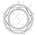
- FIG. 4 is a sectional view taken along line AA in FIG. 3.
- FIG. 4 is a sectional view taken along line CC in FIG. 3.
- FIG. 4 is a sectional view taken along line BB in FIG. 3.
- FIG. 9 is a vertical sectional side view showing a filter support structure of a dryer according to Embodiment 2.
- FIG. 10 is a vertical sectional side view showing a filter support structure of a dryer according to Embodiment 3.
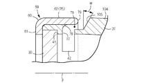
- FIG. 13 is a vertical sectional side view showing a filter support structure of a dryer according to Embodiment 4.
- FIG. 10 is a vertical sectional side view showing a filter support structure of a dryer according to Embodiment 3.
- FIG. 14 is a vertical sectional side view showing a filter support structure of a dryer according to a fifth embodiment.
- FIG. 14 is a vertical sectional side view showing a negative pressure forming structure of a dryer according to Embodiment 6.
- FIG. 14 is a longitudinal side view showing a negative pressure forming structure of a dryer according to a seventh embodiment.
- FIG. 18 is a vertical sectional side view showing a reflector of the dryer according to the eighth embodiment.
- FIGS. 1 to 11 show Embodiment 1 in which the dryer according to the present invention is applied to a hair dryer.
- the front, rear, left, right, and up and down in this embodiment follow the cross arrows shown in FIGS. 2 and 6 and the front, rear, left, right, and up and down displayed near each arrow.
- the hair dryer includes an axial-flow-type blower fan 3 that is driven to rotate by a fan motor 2 and a heat source unit 4 that serves as a heating source, inside a hollow cylindrical main body case 1 that is long in the front and rear directions. It is housed and configured.
- the main body case 1 includes a wind guide tube 7 formed by joining a pair of left and right half bodies 7a and 7b, and an outer tube 8 into which the wind guide tube 7 is fitted.
- the inner surface of the air guide tube 7 forms a wind guide passage 9 for the dry air supplied from the blower fan 3.
- An air suction port 10 is provided at the rear end of the wind guide passage 9, and air blowing is provided at the front end.
- An outlet 11 is provided.
- the air outlet 11 is surrounded by the air outlet case 5 and the auxiliary air outlet case 6, and the integrated two cases 5, 6 are engaged with the front outer surface of the wind guide cylinder 7 in a bayonet manner.
- a grip 12 is integrally formed on the rear lower surface of the wind guide cylinder 7, and a main switch 13, a light-off switch 14, a transformer 15, and the like are arranged inside the grip 12.
- Reference numeral 16 denotes a slide knob for switching the main switch 13
- reference numeral 17 denotes a push button for switching the light-off switch 14.
- reference symbol P indicates a central axis of the hair dryer.
- the inside of the air guide tube 7 is the air guide passage 9, but when the air guide tube 7 is not provided, the inside of the exterior tube 8 is the air guide passage 9. .
- a mica or metal cylinder for heat insulation may be provided on the inner surface of the wind guide cylinder 7 or the inner surface of the outer cylinder 8.
- the blower fan 3 is disposed in the rear half of the main body case 1, and pressurizes the air sucked from the suction port 10 with the blower fan 3 and sends the air toward the outlet 11.
- the fan motor 2 is fixed to the holder 21 of the fan case 20 fixed to the wind guide tube 7, and a plurality of rectifying blades 26 are formed between the fan case 20 and the holder 21.
- the fan motor 2, a halogen lamp (light emitting body) 28 described later, and a control board 22 for controlling the driving state of the ion emission structure are fixed to the front surface of the holder 21.
- the control unit When the main switch 13 is switched from the off position to the weak operation position, the control unit turns on the halogen lamp 28 in a low luminance state and drives the blower fan 3 at a low speed.
- the control unit turns on the halogen lamp 28 in a high luminance state and drives the blower fan 3 at a high speed.
- the ion emitting structure operates in both the weak operating position and the strong operating position to emit negative ions.
- the control unit temporarily turns off the halogen lamp 28.
- the outer surface of the suction port 10 is covered with a first grill 23 made of punched metal and a second grill 24 having a multi-ring shape.
- the inner surface of the outlet 11 is covered with a third grill 25.
- the second grille 24 and the third grille 25 are sandwiched and fixed between the half bodies 7a and 7b, and the first grille 23 is detachably attached to the rear part of the air guide tube 7.
- the air outlet 11 is surrounded by an air outlet case 5 fixed to the front end of the outer casing 8, and has an air outlet for drying air and an irradiation port for irradiating infrared rays (heat rays) emitted from the halogen lamp 28 to the hair of the user. Also serves as.
- the blowout port 11 is formed by integrating a blowout case 5 made of polycarbonate and an auxiliary blowout case 6 made of PPS resin which is rich in heat resistance. 7 is integrated with the wind guide cylinder 7 by bayonet engagement with an engagement wall 7c on the front outer surface of the front part 7 and by fastening the lower end of the blow-out case 5 with a screw 19 screwed from the exterior cylinder 8.
- the auxiliary blowing case 6 has an opening 96 for allowing the passage of the drying air and an ion opening 97 for allowing the passage of a part of the drying air and negative ions.
- the heat source unit 4 is composed of one unit component including a halogen lamp (luminous body) 28, a reflector 29 and a filter 30.
- the halogen lamp 28 includes a light emitting portion (filament) 36, a bulb 31 and a housing 32 which are long before and after sealing an inert gas, a halogen gas, and the like.
- the plug 33 of the housing 32 is inserted into the socket 34 and mounted. It is fixedly supported by a socket 34.
- the socket 34 is fastened and fixed to a light source table 45 described later.
- Reflector 29 is formed by joining front reflector 37 and rear reflector 38.
- the front reflector 37 is configured by joining a pair of half bodies 37a and 37b divided into right and left parts (see FIG. 7).
- Each of the half bodies 37a and 37b is formed of a molded product obtained by press-molding a metal such as aluminum, and has a reflective surface formed on an inner surface thereof.
- the reflecting surface can be formed by polishing, mirror finishing, or the like, and may be formed by plating if necessary.
- a first reflecting surface 39 for guiding the light emitted from the halogen lamp 28 forward and toward the filter 30 and a light emitted from the halogen lamp 28 to the third reflecting surface 43 are provided.
- a second reflection surface 40 that guides the light backward toward the rear is provided, and the second reflection surface 40 is formed adjacent to the first reflection surface 39.
- a filter seat 41 is formed on the inner surface of the front end of each of the half bodies 37a and 37b, and two second ventilation holes 42 are formed on the rear peripheral surface of the filter seat 41.
- the second ventilation port 42 is formed as a slit-shaped opening over the entire circumference on the wall surface near the front end of the front reflector 37 in a state where the half bodies 37a and 37b are joined.
- the front reflector 37 may be composed of a single reflecting cylinder, and in that case, it can be composed of a die-cast molded product made of a metal such as aluminum.
- the rear reflector 38 is made of a die-cast molded product made of a metal such as aluminum, and transmits the light emitted from the halogen lamp 28 and the light reflected and guided by the second reflection surface 40 to the front surface thereof toward the filter 30.
- a concave mirror-shaped third reflecting surface 43 for guiding reflection forward is provided, and a reflecting surface is formed on the inner surface thereof.
- the reflecting surface can be formed by polishing, mirror finishing, or the like, and may be formed by plating if necessary.
- a light source support structure that supports the halogen lamp 28 is provided behind the third reflection surface 43.
- the light source support structure includes a light source base 45 composed of four bosses for supporting the halogen lamp 28, and a hexagonal tubular air guide wall 46 surrounding the light source base 45.
- a first ventilation port 48 for introducing dry air into the interior of the reflector 38 is formed in the center of the third reflection surface 43.
- the wiring board 49 is provided for temporarily separating the lead wires for supplying power to the halogen lamp 28 and the lead wires for supplying power to the fan motor 2 once.
- a light source cooling passage is provided between the air guide wall 46 and the halogen lamp 28 and communicates with the first ventilation port 48.
- the wiring board 49 fixed to the light source stand 45 also functions as a light shielding plate for preventing light leaked from the first ventilation port 48 from being irradiated to the suction port 10 side.
- the first reflection surface 39, the second reflection surface 40, and the third reflection surface 43 are configured as follows.
- the first reflecting surface 39 is formed by an elliptical curved surface.
- the second reflecting surface 40 is formed as an arc surface centered on the light emitting portion 36 of the halogen lamp 28.
- the third reflecting surface 43 is formed as an elliptical curved surface or a parabolic curved surface. According to such a reflector 29, since the second reflection surface 40 is formed as an arc surface centered on the light emitting portion 36 of the halogen lamp 28, the light is emitted from the halogen lamp 28 and reflected by the second reflection surface 40.
- the trajectory of the light traveling toward the third reflecting surface 43 and the trajectory of the light directly irradiated from the halogen lamp 28 toward the third reflecting surface 43 coincide.
- the light that is reflected and guided by the first reflection surface 39 and travels toward the filter 30 and the light that is reflected and guided by the third reflection surface 43 and travels toward the filter 30 are collected outside the main body case 1 30 cm ahead of the light emitting unit 36. It has become.
- the reflector 29 including the three reflecting surfaces 39, 40, and 43
- the light emitted from the light emitter 28 and reaching each of the reflecting surfaces 39, 40, and 43 is reflected by each of the reflecting surfaces 39, 40, and 43.
- the light can be efficiently reflected and guided toward the filter 30.
- the axial center of the light emitting portion (filament) 36 of the light emitting body 28 which is long in the front and rear faces the adjacent portion between the second reflection surface 40 and the third reflection surface 43, the radial dimension of the reflector 29 is reduced. The light emitted from the illuminant 28 can be emitted toward the filter 30 while preventing the size from becoming large and realizing compactness.
- the light emitting section 36 does not need to be positioned so that the light emission center thereof coincides with the adjacent portion between the second reflection surface 40 and the third reflection surface 43. What is necessary is that it overlaps with the adjacent portion between the reflection surface 40 and the third reflection surface 43.
- the front-rear dimension of the reflector 29 including the first reflection surface 39, the second reflection surface 40, and the third reflection surface 43 is set to be larger than the radial dimension of the reflector 29, the light-emitting body 28 that is long in the front-rear direction can be used.
- the reflector 29 having an elongated cylindrical structure suitable for use can be formed, and the dryer can be made more compact because the radial dimension of the reflector 29 is smaller.
- the light source cooling passage between the air guide wall 46 and the light emitting body 28 is communicated with the first ventilation port 48, so that the dry air introduced from the rear end opening of the air guide wall 46 is It is possible to make the inside of the reflector 29 ventilate by flowing from the first vent 48 to the inside of the reflector 29. At this time, the drying air flowing from the first ventilation port 48 into the interior of the reflector 29 is brought into contact with the luminous body 28 and the reflector 29, thereby effectively cooling the luminous body 28 and the reflector 29, The temperature rise of the light emitter 28 and the reflector 29 can be suppressed.
- the light-emitting body 28 and the socket 34 can be separated from the reflector 29. Also, by removing the plug 33 from the socket 34, the luminous body 28 can be separated from the socket 34, so that the replacement operation when the luminous body 28 breaks down can be easily performed.
- the front reflector 37 and the rear reflector 38 are joined and fastened and fixed in a state where the second reflection surface 40 and the third reflection surface 43 are adjacent to each other.
- a front engaging portion (projection) 51 is formed in the rear edge 57 of the half body 37a and 37b so as to protrude radially in a bent state.
- a joining groove 52 for fitting and supporting the rear edge 57 of the front reflector 37 and a joining wall 53 for supporting the peripheral surface of the rear edge 57 of the front reflector 37 are formed.
- a recessed rear engagement portion 54 and a screw boss 55 formed by notching the joining wall 53 are formed at two opposing portions of the wall 53.
- the front reflector 37 and the rear reflector 38 can be joined by joining the pair of half bodies 37a and 37b and engaging the front engagement portion 51 and the rear engagement portion 54 with each other.
- the front reflector 37 and the rear reflector 38 can be integrated by screwing the screw 56 inserted into the through hole 51a of the front engagement portion 51 into the screw boss 55.
- the front reflector 37 and the rear reflector 38 are prevented from shifting in the radial direction by the engagement of the rear edge 57 of the front reflector 37 and the joining groove 52, and furthermore, the front reflector 37 and the rear By the engagement of the engagement portion 54, the rotation about the central axis P is prevented.
- the filter 30 is formed of low expansion glass, and is fixed to the front end of the front reflector 37 by the filter support structure 59.
- the filter support structure 59 includes a filter seat 41 formed on the front reflector 37 and a press ring 60 that cooperates with the filter seat 41 to sandwich the filter 30 back and forth.
- the press ring 60 includes an end wall 61 that presses and holds the front peripheral edge of the filter 30 and a ring-shaped circling wall 62 that fits over the outer peripheral surface of the filter seat 41. It functions as the glare 75.
- the holding ring 60 is fixed to the front reflector 37 with screws 63.
- the filter seat 41 is in close contact with the peripheral surface and the rear peripheral edge of the filter 30. Thereby, the heat of the filter 30 can be effectively conducted to the front reflector 37 side, and the cooling of the filter 30 can be promoted.
- the filter support structure 59 includes the filter seat 41 formed on the front reflector 37, and the press ring 60 for holding and fixing the filter 30 in cooperation with the seat 41.
- the filter 30 is assembled to the filter receiver 41, and the holding ring 60 is externally fitted and fixed to the front peripheral surface of the front reflector 37, so that the filter 30 is easily assembled to the front reflector 37.
- it can be firmly fixed inseparably.
- the halogen lamp 28 is vulnerable to impact, and the filament is broken or deformed when a large external force is applied.
- the heat source unit 4 is floatingly supported with respect to the main body case 1 in order to prevent an impact from acting on the halogen lamp 28. More specifically, as shown in FIG. 9, a ring-shaped spring receiving frame 64 that supports the heat source unit 4 is fixed to the inner surface of the wind guide tube 7 that surrounds the periphery of the light source support structure, and the rear reflector 38 and the spring receiving frame 64 face each other. At three places on the surface, shock absorbing springs 65 that support the heat source unit 4 are arranged.
- a hexagonal ring-shaped unit support frame 66 that supports the heat source unit 4 is fixed to the inner surface of the air guide tube 7 that surrounds the periphery of the filter 30.
- a gel-like elastic body 67 that supports the heat source unit 4 is disposed at each location.
- the spring receiving frame 64 is formed by connecting three spring arms 70 formed of leaf springs in a hexagonal frame shape.
- a spring seat 71 for receiving one end of the shock absorbing spring 65 is provided at the center of each spring arm 70. Are formed.
- a spring seat 72 for receiving the other end of the shock absorbing spring 65 is also formed on the wind guide wall 46 of the rear reflector 38 facing the spring seat 71.
- the unit support frame 66 is formed in a hexagonal frame shape by a leaf spring, and a gel holding portion 73 holding a gel-like elastic body 67 is formed at three places.
- the spring receiving frame 64 and the shock absorbing spring 65 are elastically deformed, the unit supporting frame 66 is elastically deformed, and the gel elastic body 67 absorbs the shock.
- the gel elastic body 67 absorbs the shock.
- the halogen lamp 28 is turned on, the blowing fan 3 is driven to irradiate the hair with the infrared rays passing through the filter 30, and the drying air (cooling air) sent from the blowing fan 3 is sent to the hair. Feed and dry the hair. Part of the drying air is introduced from the rear opening 58 into the air guide wall 46, and flows into the first ventilation port 48 from the light source cooling passage to cool the halogen lamp 28, the reflector 29, and the filter 30 and then to the second The air flows out of the reflector 29 through the air vent 42, merges with the dry air flowing through the air guide path 9, and is sent out from the outlet 11.
- a part of the dry air sent from the blower fan 3 flows around the heat source unit 4 along the air guide path 9 to make the area around the second vent 42 a negative pressure state. Therefore, due to the Venturi effect, the air near the second ventilation port 42 inside the reflector 29 is attracted by the dry air and merges, and is sent to the outlet 11.
- the drying air supplied from the blowing fan 3 is introduced into the air guide wall 46 from the rear opening 58 as positive pressure drying air to cool the halogen lamp 28, the reflector 29, and the filter 30. 2 It may be made to flow out of the reflector 29 from the vent 42.
- the outer surface of the second vent 42 is An anti-glare structure is provided that guides light leaking from the vent 42 in a direction away from the outlet 11.
- the anti-glare structure includes a cylindrical anti-glare body 75 that covers the outer surface of the opening of the second ventilation port 42, and in the first embodiment, the surrounding wall 62 described above also serves as the anti-glare body 75. I have.
- the orbiting wall 62 also serves as the anti-glare body 75 in this way, the number of parts is reduced by the amount of using the press ring 60 as compared with the case where the anti-glare body 75 is provided separately from the press ring 60, and Manufacturing costs can be reduced.
- the ring-shaped anti-glare body 75 covers the outer surfaces of the openings of all the second vents 42 formed in the reflector 29, and the rear end of the cylindrical wall of the anti-glare body 75 has the rear opening of the second vent 42. It protrudes backward from the edge.
- the ventilation path 76 that allows the passage of the dry air is provided between the anti-glare body 75 and the second ventilation port 42. It is formed in a recumbent L-shape in a state continuous with 42. Since the front end of the ventilation passage 76 is closed by the passage end wall 77 projecting from the front reflector 37 and abutting on the inner surface of the anti-glare body 75, the dry wind flowing into the ventilation passage 76 is reversed backward. Moving. Further, the drying air flowing out of the ventilation passage 76 reversely moves along the rear end of the passage end wall 77 and joins with the drying air flowing through the air guide passage 9.
- a rear reversing guide surface 78 for guiding the drying wind backward is formed in an inner corner portion sandwiched between the anti-glare body 75 and the passage end wall 77, and the anti-glare body is formed.
- a front reversing guide surface 79 for guiding reversal of the drying air forward is formed at the rear end of the rear surface 75 (see FIG. 1).
- the rear inversion guide surface 78 is formed of a quadrant arc surface that is continuous with the passage end wall 77, and the front inversion guide surface 79 is formed of a semicircular arc surface.
- a sustained release ring 80 for releasing cosmetic ingredients into dry air is arranged.
- the sustained-release ring 80 is formed of a porous ceramic body integrally provided with an inner ring 81, an outer ring 82, and a group of radiating walls 83 provided between the two rings. Is impregnated.
- the unit support frame 66, the sustained release ring 80, and the spring receiving frame 64 are respectively provided with three front and rear holding portions 86, and a middle holding portion 87 provided at three positions before and after the opposing surfaces of the half bodies 7a and 7b of the air guide tube 7. , And is firmly held and fixed by the rear holding portion 88.
- the ion emission structure is provided inside the wind guide tube 7 facing the outlet 11 in order to supply the negative ions to the hair together with the drying air.
- the ion emission structure includes an electrode holder 91, three central electrodes (discharge electrodes) 92 supported by the electrode holder 91, and a peripheral electrode (opposite electrode) 94 fixed to a cylindrical wall 93 surrounding the periphery of the central electrode 92. It has.
- the electrode holder 91 is clamped and fixed by a pair of clamping walls 95 provided on the wind guide cylinder 7.
- the auxiliary blowing case 6 has a through-hole 96 for sending out infrared rays and drying air, and further has an ion through-hole 97 at the center of the lower part of the case facing the center electrode 92.
- a temperature fuse 98 is arranged on an upper wall portion of the wind guide cylinder 7 on the front side of the heat source unit 4.
- the hair dryer of the first embodiment configured as described above, while the luminous body 28 and the reflector 29 are cooled by the drying air introduced into the interior of the reflector 29, the light leaked from the second vent 42 together with the drying air is prevented. It can be shielded by the glare 75 and prevent light from being emitted along the air guide path 9 toward the outlet 11. For example, light leaked from the second vent 42 is reflected by the anti-glare body 75 toward the second vent 42 or scattered by the anti-glare body 75, and further absorbed and attenuated by the anti-glare body 75. Can be done. Therefore, it is possible to reliably prevent the light leaking out of the reflector 29 from being emitted from the air outlet 11, and to provide a dryer that does not make the user feel dazzling when drying the hair.
- the anti-glare body 75 is formed in a cylindrical shape, and the rear end of the cylindrical wall of the anti-glare body 75 is formed to protrude rearward from the rear opening edge of the second ventilation port 42. Light radiated from the rear opening edge in the radial direction and light radiated diagonally forward can be reliably blocked by the inner surface of the cylindrical wall of the anti-glare body 75. A part of the light is applied to the air guide path 9 through the space between the anti-glare body 75 and the peripheral surface of the reflector 29, and the rear end of the cylindrical wall of the anti-glare body 75 is Since the light is directed backward from the rear opening edge, all the light applied to the air guide path 9 is repeatedly reflected in a state inclined backward. Therefore, it is possible to more reliably prevent the light in the air guide path 9 from being irradiated toward the outlet 11.
- the reflector 29 is configured by the front reflector 37 and the rear reflector 38, and the filter 30 disposed in front of the front reflector 37 is fixed by the filter support structure 59.
- the filter support structure 59 includes a filter seat 41 formed on the front reflector 37 and a press ring 60 for holding and fixing the filter 30 in cooperation with the seat 41. According to such a dryer, the filter 30 is assembled to the filter receiver 41, and the holding ring 60 is externally fitted and fixed to the front peripheral surface of the front reflector 37, whereby the filter 30 is easily assembled to the front reflector 37, It can be firmly fixed inseparably.
- the drying air sent from the blower fan 3 is introduced into the interior of the reflector 29 from the first ventilation port 48 and sent out from the second ventilation port 42.
- the direction of the flow of the dry air inside the reflector 29 and the direction of the flow of the dry air supplied from the blower fan 3 in the air guide path 9 can be made to coincide with each other.
- the part can be reliably introduced into the interior of the reflector 29, so that the light emitter 28 and the reflector 29 can be cooled properly.
- a ventilation passage 76 is formed between the anti-glare body 75 and the second ventilation port 42, and the drying wind is directed backward to the inner corner portion between the passage end wall 77 at the front end of the passage 76 and the anti-glare body 75.
- the reverse guide surface 78 is formed.
- the rear inversion guide surface 78 is formed at the inner corner portion between the anti-glare body 75 and the passage end wall 77, the dry wind after passing through the second ventilation port 42 is subjected to the rear inversion guide surface 78.
- the air passage 76 can be smoothly guided to the rear opening toward the rear opening.
- the flow of the drying air in the ventilation passage 76 is made to be an orderly flow, and a part of the drying air after cooling the light emitting body 28 and the reflector 29 can be prevented from staying in the second ventilation hole 42 and the ventilation passage 76. .
- a front reversing guide surface 79 is formed at the rear end of the anti-glare body 75 to guide the dry air flowing out of the ventilation passage 76 in a forward direction, the dry air flowing out of the ventilation passage 76 is prevented from flowing. Can smoothly be guided in reverse toward the outer surface side of the air passage to join the dry air flowing in the air guide passage 9.
- the front reflector 37 and the rear reflector 38 are joined to form the reflector 29, and the front and rear reflectors 37 and 38 are engaged with the joining surface of the front reflector 37 and the rear reflector 38 to restrict the slipping movement of the joining partner.
- the joint portion 51 and the rear engagement portion 54 are formed. According to such a reflector 29, the front engagement portion 51 and the rear engagement portion 54 are engaged with each other in a concave-convex manner, so that the front reflector 37 and the rear reflector 38 can be properly adjusted in a state where the displacement of the mating partner is restricted and positioned. Can be assembled.
- the screw 56 inserted into one of the front engagement portion 51 and the rear engagement portion 54 is screwed into the screw boss 55 provided on the other, so that the front reflector 37 and the rear reflector 38 are fixed inseparably.
- the front reflector 37 and the rear reflector 38 can be firmly fastened and fixed with the screw 56 while having a simpler fastening structure. Therefore, the optical characteristics of the reflecting surfaces 39, 40, and 43 provided on the reflector 29 can always be kept constant.
- the front reflector 37 is formed by joining a pair of half bodies 37a and 37b, and a front engagement that falls into and engages with the rear engagement portion 54 of the rear reflector 38 on the joining surface of the half bodies 37a and 37b.
- the front reflector 37 may be constituted by one reflecting cylinder. In that case, it can be constituted by a die-cast molded product made of a metal such as aluminum. Further, the front engagement portion 51, the rear engagement portion 54, and the screw 56 need not be provided at two opposing positions, and can be formed at only one position.
- FIG. 12 shows Embodiment 2 of a dryer in which the filter support structure 59 is changed.
- the holding ring 60 is formed integrally with the half bodies 7a and 7b of the air guide cylinder 7, and the rib 99 provided on the inner surfaces of the half bodies 7a and 7b is used to form the half ring of the holding ring 60.
- 60a and 60b a circular second vent 42 is formed between the front opening of the front reflector 37 and the rear surface of the press ring 60, and the filter 30 and the third
- the difference from the first embodiment is that the grill 25 and the half ring 60a and 60b are sandwiched and fixed.
- the other components are the same as those in the first embodiment, and thus the same members are denoted by the same reference numerals and description thereof will be omitted. The same applies to the following embodiments.
- the drying air can be smoothly sent out from the second ventilation port 42.
- the cooling of the luminous body 28 and the reflector 29 by the drying air can be effectively performed.
- the number of parts can be reduced by the amount that the anti-glare body 75 and the filter support structure 59 are formed integrally with the pair of half rings 60a and 60b, so that the manufacturing cost of the dryer can be reduced. Since there is no need to provide the third grill 25 in the outlet 11, there is also an advantage that the structure of the outlet 11 can be simplified.
- the filter 30 Since the filter 30 is supported by the holding ring 60 separate from the reflector 29, the emission of visible light from the air outlet 11 is reliably attenuated, and the user does not feel dazzling when drying the hair. Dryer can be provided.
- the reflector 29 and the filter support structure 59 are independently supported, the luminous body 28 can be removed from the socket 34 when the main body case 1 is disassembled, and replacement of the luminous body 28 can be reduced. Can be easily performed. There is also an advantage that the heat source unit 4 can be reduced in weight.
- FIG. 13 shows Embodiment 3 of a dryer in which the filter support structure 59 is changed.
- the front reflector 37 is constituted by a front reflector body 101 and a rear reflector body 102
- the front reflector body 101 is constituted by half bodies 101a and 101b
- the filter 30 is formed by half bodies 101a and 101b.
- the holding ring 60 was formed integrally with the half bodies 101a and 101b, and the anti-glare structure and the filter support structure were integrated with the pair of half bodies 101a and 101b.
- a group of round holes opened at regular intervals along the peripheral surface of the front reflector body 101 function as the second ventilation holes 42. According to such a reflector structure, the anti-glare structure and the filter support structure can be integrated with the pair of half bodies 101a and 101b, so that the filter support structure 59 can be simplified.
- FIG. 14 shows a fourth embodiment of a dryer in which a partial structure of the front reflector 37 is changed.
- a throttle part (negative pressure forming structure) 104 for reducing the passage cross-sectional area of the air guide path 9 surrounding the front reflector 37. are bulged. More specifically, the peripheral surface of the front reflector 37 is formed to have a tapered shape with the front expanding, and the outer surface of the front end surface 105 of the narrowed portion 104 is flush with the virtual outer surface passing through the outer surface of the antiglare body 75.
- the front reflector 37 is formed of a plastic molded product, and a reflection film serving as the first reflection surface 39 and the second reflection surface 40 is formed on the inner surface thereof.
- the reflection film may be formed by, for example, plating.
- FIG. 15 shows a fifth embodiment of a dryer in which the front end structure of the squeezing section 104 is changed.
- a tapered diaphragm 104 is formed on the peripheral surface of the front reflector 37 so as to expand forward, but the front end surface 105 of the diaphragm 104 facing the rear end of the anti-glare 75 is formed. Is inclined backward by a predetermined angle ⁇ with respect to the center axis P of the main body case 1.
- FIG. 16 shows a sixth embodiment of a dryer in which a partial structure of the front reflector 37 is changed.
- a negative pressure forming structure is formed on the peripheral surface of the front reflector 37.
- an aperture ring 112 for reducing the cross-sectional area of the air guide path 9 surrounding the front reversing guide surface 79 is disposed around the front reversing guide surface 79 provided at the rear end of the anti-glare body 75.
- the aperture ring 112 forms the negative pressure forming structure 106.
- An aperture surface 107 whose front side is curved is provided on the inner surface of the aperture ring 112, and the peripheral surface of the ring is fixed to the wind guide cylinder 7 surrounding the periphery of the front reversing guide surface 79.
- the aperture ring 112 is formed of a porous ceramic body similarly to the sustained release ring 80 of the first embodiment, and its porous portion is impregnated with a cosmetic ingredient such as vitamin or collagen.
- the passage cross-sectional area of the air guide path 9 surrounding the periphery of the front reflector 37 is gradually reduced, and the air flows around the front reflector 37.
- the flow rate can be increased by reducing the pressure of the drying air. Accordingly, the periphery of the drying air discharged from the ventilation passage 76 is surrounded by the flow of the drying air having a high flow velocity, so that the drying air flowing from the ventilation passage 76 to the periphery of the front reversing guide surface 79 is dried. It can be surely merged by the wind and can be smoothly fed toward the outlet 11.
- the pressure of the drying air discharged from the ventilation passage 76 is higher than the pressure of the drying air flowing around the anti-glare body 75, the drying air flowing around the anti-glare body 75 flows from the ventilation passage 76 to the reflector 29. It can be prevented from getting inside. Since the speed of the drying air can be increased by the drawing ring 112 having a simple structure, the structure of the negative pressure forming structure 106 can be simplified and the manufacturing cost of the dryer can be reduced. Furthermore, if the cosmetic component is impregnated and held in the aperture ring 112 formed of a porous body, the cosmetic component such as collagen or vitamin is released into the dry air that comes into contact with the aperture ring 112 while flowing through the air guide path 9, Can be supplied from the outlet 11. In addition, since the drying air containing the beauty component sent from the outlet 11 adheres to the hair and the scalp, it is possible to provide a dryer capable of exhibiting a beauty effect along with the drying of the hair.
- FIG. 17 shows a dryer 7 in which a part of the structure of the front reflector 37 is changed. Also in the seventh embodiment, a negative pressure forming structure is formed on the peripheral surface of the front reflector 37. Specifically, a venturi cylinder 108 having an inner cylinder 109 and an outer cylinder 110 is arranged between the front reflector 37 and the air guide cylinder 7, and a front narrowing ring shape is provided between the inner cylinder 109 and the outer cylinder 110. Are formed.
- the inner tube 109 is formed by a curved tube that expands forward
- the outer tube 110 is formed by a tapered tube that narrows forward
- the two tubes 109 and 110 are formed by an anti-glare body from the narrow portion of the first reflection surface 39 and the second reflection surface 40. 75 are provided near the rear.
- the inner cylinder 109 and the outer cylinder 110 are connected by a plurality of radial ribs. As described above, when the venturi cylinder 108 is disposed around the front reflector 37, the speed of the drying air passing through the throttle passage 111 can be remarkably increased.
- drying air flowing from the ventilation passage 76 to the outside of the anti-glare body 75 via the front reversing guide surface 79 can be combined by the suction effect of the high-speed drying air flowing out of the venturi tube 108.
- the halogen lamp 28 and the reflector 29 can be effectively cooled by the drying air.
- FIG. 18 shows an eighth embodiment of the dryer.
- the passage of the drying air inside the reflector 29 is set to be opposite to the passage of the drying air in the first embodiment.
- the dry air supplied from the blower fan 3 is introduced into the interior of the reflector 29 from the second ventilation port 42 and is transmitted from the first ventilation port 48, and is transmitted from the ventilation outlet 114 opened in the air guide wall 46 to the reflector. It is sent out of 29.
- the anti-glare body 75 also functions as the wind guide 115 for collecting air.
- the air guide 115 is formed so as to protrude greatly from the rear end edge of the ventilation passage 76 to the rear side, and is formed as a curved wall having a front-recessed shape. The guide is reversed toward 42.
- a baffle plate 116 is disposed on the rear outer surface of the first ventilation port 48.
- the baffle plate 116 is formed in a ring shape having a diameter larger than the diameter of the first ventilation port 48, and is supported by a plurality of radiation walls protruding from the inner surface of the baffle wall 46. It faces the rear surface.
- the air guide wall 46 is configured as an independent component separate from the rear reflector 38.
- the flow of the dry air flowing from the second ventilation port 42 to the first ventilation port 48 inside the reflector 29 is made smooth and suitable, and the luminous body 28 and the reflector 29 are cooled more effectively.
- the drying air can take a passing form in which the inside of the reflector 29 flows backward.
- a part of the dry air flowing toward the air outlet 11 through the air guide path 9 is reversely guided by the air guide 115 and introduced into the interior of the reflector 29 from the second ventilation port 42 to emit light.
- the body 28 and the reflector 29 After the body 28 and the reflector 29 have cooled, they can be delivered from the first vent 48.
- the drying air is received by the air guide 115 protruding around the reflector 29 and guided in reverse, more drying air is introduced into the inside of the reflector 29, and the luminous body 28 and the reflector 29 are effectively formed. Can be cooled.
- the hair dryer described in each of the above embodiments can be implemented in the form of a light irradiation device described below.
- the light irradiation device include a phototherapy device that irradiates light to an affected part, and a light drying device that irradiates light to a drying target to promote drying.
- the light irradiating device includes a light emitter 28 and a reflector 29 that reflects and guides the light emitted from the light emitter 28 toward an irradiation target.
- the reflector 29 has an irradiation opening at a front portion thereof.
- Reference numeral 29 denotes a first reflection surface 39 for guiding the light emitted from the light emitter 28 toward the irradiation opening in a forward direction, and is disposed adjacent to the first reflection surface 39 so as to face the light emitted from the light emitter 28 backward.
- a second reflecting surface 40 for reflecting and guiding the light, and a light emitted from the light emitter 28 and a light reflected and guided by the second reflecting surface 40 are directed forward toward the irradiation opening.
- a light irradiating device in which a third reflecting surface 43 for guiding reflection is provided, and a light emitting portion 36 of the luminous body 28 faces a portion adjacent to the second reflecting surface 40 and the third reflecting surface 43. According to the above-described light irradiation device, the light emitted from the light emitter 28 and reaching each of the reflection surfaces 39, 40, and 43 is efficiently reflected and guided by each of the reflection surfaces 39, 40, and 43, and is emitted to the filter 30. be able to.
- the light-emitting portion 36 of the light-emitting body 28 that is long in the front and rear faces the portion adjacent to the second reflection surface 40 and the third reflection surface 43, it is possible to prevent the radial dimension of the reflector 29 from being increased, and to reduce the size.
- the light emitted from the illuminant 28 can be emitted toward the filter 30 while realizing the image quality. This is because when the light emitted from the light emitting body 28 is reflected and guided by, for example, only one reflecting surface, the diameter of the irradiation opening of the reflector 29 becomes large, and the reflector 29 becomes large accordingly. Because it becomes.
- the reflector 29 having an elongated cylindrical structure suitable for using the long light emitter 28 in the front and rear direction can be formed, and the light irradiation device can be made more compact as the radial dimension of the reflector 29 is smaller.
- a light irradiation device in which a filter 30 is disposed at an irradiation opening at a front part of a reflector 29. According to such a light irradiation device, it is possible to reliably prevent the unattenuated visible light from being emitted from the irradiation opening, so that it is possible to provide a light irradiation device that does not make the user feel dazzled during use.
- the reflector 29 is formed by joining the front reflector 37 and the rear reflector 38, and the filter 30 is disposed at the front of the front reflector 37, and is fixed to the front reflector 37 by the filter support structure 59.
- Reference numeral 59 denotes a filter receiving seat 41 formed on the inner surface of the front end of the front reflector 37, and a press ring 60 which is externally fitted and fixed on the front peripheral surface of the front reflector 37 and cooperates with the filter receiving seat 41 to clamp and fix the filter 30.
- a light irradiation device comprising: According to such a light irradiation device, the filter 30 is easily assembled to the front reflector 37 by assembling the filter 30 to the filter seat 41 and externally fixing the holding ring 60 to the front peripheral surface of the front reflector 37. And can be firmly fixed inseparably.
- the reflector 29 is configured by joining a front reflector 37 and a rear reflector 38.
- a light irradiation device in which a front engaging portion 51 and a rear engaging portion 54 are formed on the joining surface of the front reflector 37 and the rear reflector 38 so as to engage and recess with each other to regulate the displacement of the joining partner.
- the front reflector 37 and the rear reflector 38 are properly adjusted in a state where the front engagement portion 51 and the rear engagement portion 54 are engaged and recessed with each other, thereby restricting and positioning the joining partner. Can be assembled.
- a screw 56 inserted into one of the front engagement portion 51 and the rear engagement portion 54 is screwed into a screw boss 55 provided on the other, so that the front reflector 37 and the rear reflector 38 are fixed inseparably. apparatus.
- the front reflector 37 and the rear reflector 38 can be firmly fastened and fixed with the screws 56 while having a simpler fastening structure. Therefore, the optical characteristics of the reflecting surfaces 39, 40, and 43 provided on the reflector 29 can always be kept constant.
- the front reflector 37 is formed by joining a pair of divided half bodies 37a and 37b, and the joining surface of the rear reflector 38 includes a joining groove 52 for fitting and supporting the rear edge of the front reflector 37.
- a joining wall 53 for supporting a rear edge peripheral surface of the front reflector 37 is formed, and a concave rear engaging portion 54 formed by notching the joining wall 53 and a screw boss 55 are formed at a plurality of portions of the joining wall 53.
- the luminous body 28 may be an incandescent lamp, a xenon lamp, a metal halide lamp, or the like, in addition to the halogen lamp.
- the term “filter that blocks transmission of visible light” does not mean that visible light is completely blocked, but has the same meaning as that of attenuating visible light.
- a filter that can completely block visible light and emit only heat rays (infrared light) may be used.
- the second ventilation hole 42 is intermittently constituted by a group of slits having a small circumferential length, it is not necessary to form the anti-glare body 75 in a cylindrical shape, and a group of groups covering the outer surface of each slit. It may be constituted by an anti-glare wall.
- the air suction port 10 is formed on the rear end rear surface of the main body case 1 as in each of the above embodiments. It may be a formed form.
- the suction port 10 provided at one end (rear end) of the air guide path 9 according to the present invention is meant to include these forms.
- the blower fan 3 is constituted by a propeller type or impeller type axial fan, a centripetal fan, or the like.
- the shape of the reflector 29 can be changed as appropriate according to the manner in which infrared light is emitted to the object to be dried.
- the dryer according to the present invention is not limited to hair dryers for drying hair, but can be applied not only to body parts such as limbs and nails, but also to animal dryers such as dogs and cats, not only for humans, but also for clothing. It can also be applied to clothing dryers.
- the dryer of the present invention is a hair iron having a dryer function, as long as it is a device that irradiates light to the object to be dried, for example, a hair can be shaped into a curled shape or a straight shape while drying hair. Also applicable to
Landscapes
- Engineering & Computer Science (AREA)
- Mechanical Engineering (AREA)
- General Engineering & Computer Science (AREA)
- Chemical & Material Sciences (AREA)
- Combustion & Propulsion (AREA)
- Life Sciences & Earth Sciences (AREA)
- Microbiology (AREA)
- Cleaning And Drying Hair (AREA)
- Drying Of Solid Materials (AREA)
Applications Claiming Priority (2)
| Application Number | Priority Date | Filing Date | Title |
|---|---|---|---|
| JP2018-185612 | 2018-09-28 | ||
| JP2018185612A JP7092631B2 (ja) | 2018-09-28 | 2018-09-28 | ドライヤー |
Publications (1)
| Publication Number | Publication Date |
|---|---|
| WO2020066500A1 true WO2020066500A1 (ja) | 2020-04-02 |
Family
ID=69949650
Family Applications (1)
| Application Number | Title | Priority Date | Filing Date |
|---|---|---|---|
| PCT/JP2019/034669 Ceased WO2020066500A1 (ja) | 2018-09-28 | 2019-09-03 | ドライヤー |
Country Status (2)
| Country | Link |
|---|---|
| JP (2) | JP7092631B2 (https=) |
| WO (1) | WO2020066500A1 (https=) |
Cited By (5)
| Publication number | Priority date | Publication date | Assignee | Title |
|---|---|---|---|---|
| CN113573609A (zh) * | 2020-05-09 | 2021-10-29 | 深圳汝原科技有限公司 | 干燥设备 |
| CN114431590A (zh) * | 2022-01-29 | 2022-05-06 | 无锡睿米信息技术有限公司 | 一种具有透光结构的吹风机 |
| CN114711528A (zh) * | 2022-04-26 | 2022-07-08 | 深圳市乐美科技有限公司 | 吹风机 |
| US20230363510A1 (en) * | 2020-05-09 | 2023-11-16 | Sz Zuvi Technology Co., Ltd. | Apparatuses and methods for safely drying an object |
| EP4440370A4 (en) * | 2021-12-31 | 2025-01-08 | SZ Zuvi Technology Co., Ltd. | Attachments and drying apparatuses having attachments |
Families Citing this family (1)
| Publication number | Priority date | Publication date | Assignee | Title |
|---|---|---|---|---|
| JP7469182B2 (ja) * | 2020-08-25 | 2024-04-16 | 鹿島建設株式会社 | コンクリート構造物の冷却装置及び冷却方法 |
Citations (3)
| Publication number | Priority date | Publication date | Assignee | Title |
|---|---|---|---|---|
| DE2950001A1 (de) * | 1979-12-12 | 1981-06-19 | Bosch-Siemens Hausgeräte GmbH, 7000 Stuttgart | Elektischer haartrockner |
| WO2016072031A1 (ja) * | 2014-11-07 | 2016-05-12 | 株式会社イデア | ドライヤー |
| WO2018021309A1 (ja) * | 2016-07-29 | 2018-02-01 | 日立マクセル株式会社 | ヘアードライヤー |
Family Cites Families (3)
| Publication number | Priority date | Publication date | Assignee | Title |
|---|---|---|---|---|
| US3792230A (en) * | 1972-03-30 | 1974-02-12 | Industrial Innovations Inc | Gas-cooled torch lamp |
| JP2012194228A (ja) | 2011-03-15 | 2012-10-11 | Seiko Epson Corp | 光源装置及びプロジェクター |
| JP2018023754A (ja) | 2016-07-29 | 2018-02-15 | マクセルホールディングス株式会社 | ヘアードライヤー |
-
2018
- 2018-09-28 JP JP2018185612A patent/JP7092631B2/ja active Active
-
2019
- 2019-09-03 WO PCT/JP2019/034669 patent/WO2020066500A1/ja not_active Ceased
-
2022
- 2022-06-14 JP JP2022095659A patent/JP7386931B2/ja active Active
Patent Citations (3)
| Publication number | Priority date | Publication date | Assignee | Title |
|---|---|---|---|---|
| DE2950001A1 (de) * | 1979-12-12 | 1981-06-19 | Bosch-Siemens Hausgeräte GmbH, 7000 Stuttgart | Elektischer haartrockner |
| WO2016072031A1 (ja) * | 2014-11-07 | 2016-05-12 | 株式会社イデア | ドライヤー |
| WO2018021309A1 (ja) * | 2016-07-29 | 2018-02-01 | 日立マクセル株式会社 | ヘアードライヤー |
Cited By (7)
| Publication number | Priority date | Publication date | Assignee | Title |
|---|---|---|---|---|
| CN113573609A (zh) * | 2020-05-09 | 2021-10-29 | 深圳汝原科技有限公司 | 干燥设备 |
| US20230363510A1 (en) * | 2020-05-09 | 2023-11-16 | Sz Zuvi Technology Co., Ltd. | Apparatuses and methods for safely drying an object |
| US12402704B2 (en) * | 2020-05-09 | 2025-09-02 | Sz Zuvi Technology Co., Ltd. | Apparatuses and methods for safely drying an object |
| EP4440370A4 (en) * | 2021-12-31 | 2025-01-08 | SZ Zuvi Technology Co., Ltd. | Attachments and drying apparatuses having attachments |
| CN114431590A (zh) * | 2022-01-29 | 2022-05-06 | 无锡睿米信息技术有限公司 | 一种具有透光结构的吹风机 |
| CN114711528A (zh) * | 2022-04-26 | 2022-07-08 | 深圳市乐美科技有限公司 | 吹风机 |
| CN114711528B (zh) * | 2022-04-26 | 2025-08-29 | 东莞市乐美智能科技有限公司 | 吹风机 |
Also Published As
| Publication number | Publication date |
|---|---|
| JP2020054495A (ja) | 2020-04-09 |
| JP2022113798A (ja) | 2022-08-04 |
| JP7386931B2 (ja) | 2023-11-27 |
| JP7092631B2 (ja) | 2022-06-28 |
Similar Documents
| Publication | Publication Date | Title |
|---|---|---|
| JP7386931B2 (ja) | 光照射装置 | |
| JP7129298B2 (ja) | ドライヤー | |
| JP7179585B2 (ja) | ドライヤー | |
| CN111093421B (zh) | 吹风机 | |
| KR20200033093A (ko) | 드라이어 | |
| US4323761A (en) | Radiant heat hair dryer | |
| US6381407B2 (en) | Lamp heat generating apparatus | |
| WO2018021309A1 (ja) | ヘアードライヤー | |
| JP2005177234A (ja) | ヘアドライヤー | |
| JP2018023754A (ja) | ヘアードライヤー | |
| JP7132831B2 (ja) | 光照射装置 | |
| CN210290191U (zh) | 风扇组件以及风扇和镜子组件 | |
| JP7149798B2 (ja) | 光照射装置 | |
| CN106051651B (zh) | 用于冷却灯具的至少一个光源的冷却组件及灯具 | |
| JP7521877B2 (ja) | 光照射装置 | |
| JP2020130718A (ja) | ドライヤー | |
| CN114173606B (zh) | 干燥装置 | |
| JP4674768B2 (ja) | ヘアードライヤー | |
| JP4493144B2 (ja) | 照明器具 | |
| US1541988A (en) | Method of and means for drying | |
| CN222585371U (zh) | 光疗美容仪 | |
| CN222533955U (zh) | 光疗美容仪 | |
| JP2026062099A (ja) | 乾燥装置 | |
| JP7300359B2 (ja) | ヘアードライヤー | |
| KR20030066890A (ko) | 선풍기형 팬히터 |
Legal Events
| Date | Code | Title | Description |
|---|---|---|---|
| 121 | Ep: the epo has been informed by wipo that ep was designated in this application |
Ref document number: 19866880 Country of ref document: EP Kind code of ref document: A1 |
|
| NENP | Non-entry into the national phase |
Ref country code: DE |
|
| 122 | Ep: pct application non-entry in european phase |
Ref document number: 19866880 Country of ref document: EP Kind code of ref document: A1 |