WO2020065952A1 - セラミックス構造体およびガスセンサのセンサ素子 - Google Patents
セラミックス構造体およびガスセンサのセンサ素子 Download PDFInfo
- Publication number
- WO2020065952A1 WO2020065952A1 PCT/JP2018/036400 JP2018036400W WO2020065952A1 WO 2020065952 A1 WO2020065952 A1 WO 2020065952A1 JP 2018036400 W JP2018036400 W JP 2018036400W WO 2020065952 A1 WO2020065952 A1 WO 2020065952A1
- Authority
- WO
- WIPO (PCT)
- Prior art keywords
- ceramic
- protective layer
- sensor element
- particles
- gas
- Prior art date
- Legal status (The legal status is an assumption and is not a legal conclusion. Google has not performed a legal analysis and makes no representation as to the accuracy of the status listed.)
- Ceased
Links
Images



Classifications
-
- G—PHYSICS
- G01—MEASURING; TESTING
- G01N—INVESTIGATING OR ANALYSING MATERIALS BY DETERMINING THEIR CHEMICAL OR PHYSICAL PROPERTIES
- G01N27/00—Investigating or analysing materials by the use of electric, electrochemical, or magnetic means
- G01N27/26—Investigating or analysing materials by the use of electric, electrochemical, or magnetic means by investigating electrochemical variables; by using electrolysis or electrophoresis
- G01N27/403—Cells and electrode assemblies
- G01N27/406—Cells and probes with solid electrolytes
- G01N27/407—Cells and probes with solid electrolytes for investigating or analysing gases
- G01N27/4077—Means for protecting the electrolyte or the electrodes
-
- C—CHEMISTRY; METALLURGY
- C04—CEMENTS; CONCRETE; ARTIFICIAL STONE; CERAMICS; REFRACTORIES
- C04B—LIME, MAGNESIA; SLAG; CEMENTS; COMPOSITIONS THEREOF, e.g. MORTARS, CONCRETE OR LIKE BUILDING MATERIALS; ARTIFICIAL STONE; CERAMICS; REFRACTORIES; TREATMENT OF NATURAL STONE
- C04B35/00—Shaped ceramic products characterised by their composition; Ceramics compositions; Processing powders of inorganic compounds preparatory to the manufacturing of ceramic products
- C04B35/01—Shaped ceramic products characterised by their composition; Ceramics compositions; Processing powders of inorganic compounds preparatory to the manufacturing of ceramic products based on oxide ceramics
- C04B35/48—Shaped ceramic products characterised by their composition; Ceramics compositions; Processing powders of inorganic compounds preparatory to the manufacturing of ceramic products based on oxide ceramics based on zirconium or hafnium oxides, zirconates, zircon or hafnates
- C04B35/486—Fine ceramics
-
- B—PERFORMING OPERATIONS; TRANSPORTING
- B32—LAYERED PRODUCTS
- B32B—LAYERED PRODUCTS, i.e. PRODUCTS BUILT-UP OF STRATA OF FLAT OR NON-FLAT, e.g. CELLULAR OR HONEYCOMB, FORM
- B32B18/00—Layered products essentially comprising ceramics, e.g. refractory products
-
- C—CHEMISTRY; METALLURGY
- C04—CEMENTS; CONCRETE; ARTIFICIAL STONE; CERAMICS; REFRACTORIES
- C04B—LIME, MAGNESIA; SLAG; CEMENTS; COMPOSITIONS THEREOF, e.g. MORTARS, CONCRETE OR LIKE BUILDING MATERIALS; ARTIFICIAL STONE; CERAMICS; REFRACTORIES; TREATMENT OF NATURAL STONE
- C04B35/00—Shaped ceramic products characterised by their composition; Ceramics compositions; Processing powders of inorganic compounds preparatory to the manufacturing of ceramic products
- C04B35/01—Shaped ceramic products characterised by their composition; Ceramics compositions; Processing powders of inorganic compounds preparatory to the manufacturing of ceramic products based on oxide ceramics
- C04B35/10—Shaped ceramic products characterised by their composition; Ceramics compositions; Processing powders of inorganic compounds preparatory to the manufacturing of ceramic products based on oxide ceramics based on aluminium oxide
- C04B35/111—Fine ceramics
- C04B35/117—Composites
-
- C—CHEMISTRY; METALLURGY
- C04—CEMENTS; CONCRETE; ARTIFICIAL STONE; CERAMICS; REFRACTORIES
- C04B—LIME, MAGNESIA; SLAG; CEMENTS; COMPOSITIONS THEREOF, e.g. MORTARS, CONCRETE OR LIKE BUILDING MATERIALS; ARTIFICIAL STONE; CERAMICS; REFRACTORIES; TREATMENT OF NATURAL STONE
- C04B35/00—Shaped ceramic products characterised by their composition; Ceramics compositions; Processing powders of inorganic compounds preparatory to the manufacturing of ceramic products
- C04B35/01—Shaped ceramic products characterised by their composition; Ceramics compositions; Processing powders of inorganic compounds preparatory to the manufacturing of ceramic products based on oxide ceramics
- C04B35/44—Shaped ceramic products characterised by their composition; Ceramics compositions; Processing powders of inorganic compounds preparatory to the manufacturing of ceramic products based on oxide ceramics based on aluminates
- C04B35/443—Magnesium aluminate spinel
-
- C—CHEMISTRY; METALLURGY
- C04—CEMENTS; CONCRETE; ARTIFICIAL STONE; CERAMICS; REFRACTORIES
- C04B—LIME, MAGNESIA; SLAG; CEMENTS; COMPOSITIONS THEREOF, e.g. MORTARS, CONCRETE OR LIKE BUILDING MATERIALS; ARTIFICIAL STONE; CERAMICS; REFRACTORIES; TREATMENT OF NATURAL STONE
- C04B35/00—Shaped ceramic products characterised by their composition; Ceramics compositions; Processing powders of inorganic compounds preparatory to the manufacturing of ceramic products
- C04B35/622—Forming processes; Processing powders of inorganic compounds preparatory to the manufacturing of ceramic products
- C04B35/626—Preparing or treating the powders individually or as batches ; preparing or treating macroscopic reinforcing agents for ceramic products, e.g. fibres; mechanical aspects section B
- C04B35/628—Coating the powders or the macroscopic reinforcing agents
- C04B35/62802—Powder coating materials
- C04B35/62805—Oxide ceramics
- C04B35/62807—Silica or silicates
-
- C—CHEMISTRY; METALLURGY
- C04—CEMENTS; CONCRETE; ARTIFICIAL STONE; CERAMICS; REFRACTORIES
- C04B—LIME, MAGNESIA; SLAG; CEMENTS; COMPOSITIONS THEREOF, e.g. MORTARS, CONCRETE OR LIKE BUILDING MATERIALS; ARTIFICIAL STONE; CERAMICS; REFRACTORIES; TREATMENT OF NATURAL STONE
- C04B35/00—Shaped ceramic products characterised by their composition; Ceramics compositions; Processing powders of inorganic compounds preparatory to the manufacturing of ceramic products
- C04B35/622—Forming processes; Processing powders of inorganic compounds preparatory to the manufacturing of ceramic products
- C04B35/626—Preparing or treating the powders individually or as batches ; preparing or treating macroscopic reinforcing agents for ceramic products, e.g. fibres; mechanical aspects section B
- C04B35/628—Coating the powders or the macroscopic reinforcing agents
- C04B35/62802—Powder coating materials
- C04B35/62805—Oxide ceramics
- C04B35/6281—Alkaline earth metal oxides
-
- C—CHEMISTRY; METALLURGY
- C04—CEMENTS; CONCRETE; ARTIFICIAL STONE; CERAMICS; REFRACTORIES
- C04B—LIME, MAGNESIA; SLAG; CEMENTS; COMPOSITIONS THEREOF, e.g. MORTARS, CONCRETE OR LIKE BUILDING MATERIALS; ARTIFICIAL STONE; CERAMICS; REFRACTORIES; TREATMENT OF NATURAL STONE
- C04B35/00—Shaped ceramic products characterised by their composition; Ceramics compositions; Processing powders of inorganic compounds preparatory to the manufacturing of ceramic products
- C04B35/622—Forming processes; Processing powders of inorganic compounds preparatory to the manufacturing of ceramic products
- C04B35/626—Preparing or treating the powders individually or as batches ; preparing or treating macroscopic reinforcing agents for ceramic products, e.g. fibres; mechanical aspects section B
- C04B35/628—Coating the powders or the macroscopic reinforcing agents
- C04B35/62802—Powder coating materials
- C04B35/62805—Oxide ceramics
- C04B35/62813—Alumina or aluminates
-
- C—CHEMISTRY; METALLURGY
- C04—CEMENTS; CONCRETE; ARTIFICIAL STONE; CERAMICS; REFRACTORIES
- C04B—LIME, MAGNESIA; SLAG; CEMENTS; COMPOSITIONS THEREOF, e.g. MORTARS, CONCRETE OR LIKE BUILDING MATERIALS; ARTIFICIAL STONE; CERAMICS; REFRACTORIES; TREATMENT OF NATURAL STONE
- C04B35/00—Shaped ceramic products characterised by their composition; Ceramics compositions; Processing powders of inorganic compounds preparatory to the manufacturing of ceramic products
- C04B35/622—Forming processes; Processing powders of inorganic compounds preparatory to the manufacturing of ceramic products
- C04B35/626—Preparing or treating the powders individually or as batches ; preparing or treating macroscopic reinforcing agents for ceramic products, e.g. fibres; mechanical aspects section B
- C04B35/628—Coating the powders or the macroscopic reinforcing agents
- C04B35/62802—Powder coating materials
- C04B35/62805—Oxide ceramics
- C04B35/62818—Refractory metal oxides
- C04B35/62821—Titanium oxide
-
- C—CHEMISTRY; METALLURGY
- C04—CEMENTS; CONCRETE; ARTIFICIAL STONE; CERAMICS; REFRACTORIES
- C04B—LIME, MAGNESIA; SLAG; CEMENTS; COMPOSITIONS THEREOF, e.g. MORTARS, CONCRETE OR LIKE BUILDING MATERIALS; ARTIFICIAL STONE; CERAMICS; REFRACTORIES; TREATMENT OF NATURAL STONE
- C04B35/00—Shaped ceramic products characterised by their composition; Ceramics compositions; Processing powders of inorganic compounds preparatory to the manufacturing of ceramic products
- C04B35/622—Forming processes; Processing powders of inorganic compounds preparatory to the manufacturing of ceramic products
- C04B35/626—Preparing or treating the powders individually or as batches ; preparing or treating macroscopic reinforcing agents for ceramic products, e.g. fibres; mechanical aspects section B
- C04B35/628—Coating the powders or the macroscopic reinforcing agents
- C04B35/62802—Powder coating materials
- C04B35/62805—Oxide ceramics
- C04B35/62818—Refractory metal oxides
- C04B35/62823—Zirconium or hafnium oxide
-
- C—CHEMISTRY; METALLURGY
- C04—CEMENTS; CONCRETE; ARTIFICIAL STONE; CERAMICS; REFRACTORIES
- C04B—LIME, MAGNESIA; SLAG; CEMENTS; COMPOSITIONS THEREOF, e.g. MORTARS, CONCRETE OR LIKE BUILDING MATERIALS; ARTIFICIAL STONE; CERAMICS; REFRACTORIES; TREATMENT OF NATURAL STONE
- C04B35/00—Shaped ceramic products characterised by their composition; Ceramics compositions; Processing powders of inorganic compounds preparatory to the manufacturing of ceramic products
- C04B35/622—Forming processes; Processing powders of inorganic compounds preparatory to the manufacturing of ceramic products
- C04B35/626—Preparing or treating the powders individually or as batches ; preparing or treating macroscopic reinforcing agents for ceramic products, e.g. fibres; mechanical aspects section B
- C04B35/628—Coating the powders or the macroscopic reinforcing agents
- C04B35/62892—Coating the powders or the macroscopic reinforcing agents with a coating layer consisting of particles
-
- C—CHEMISTRY; METALLURGY
- C04—CEMENTS; CONCRETE; ARTIFICIAL STONE; CERAMICS; REFRACTORIES
- C04B—LIME, MAGNESIA; SLAG; CEMENTS; COMPOSITIONS THEREOF, e.g. MORTARS, CONCRETE OR LIKE BUILDING MATERIALS; ARTIFICIAL STONE; CERAMICS; REFRACTORIES; TREATMENT OF NATURAL STONE
- C04B35/00—Shaped ceramic products characterised by their composition; Ceramics compositions; Processing powders of inorganic compounds preparatory to the manufacturing of ceramic products
- C04B35/622—Forming processes; Processing powders of inorganic compounds preparatory to the manufacturing of ceramic products
- C04B35/626—Preparing or treating the powders individually or as batches ; preparing or treating macroscopic reinforcing agents for ceramic products, e.g. fibres; mechanical aspects section B
- C04B35/63—Preparing or treating the powders individually or as batches ; preparing or treating macroscopic reinforcing agents for ceramic products, e.g. fibres; mechanical aspects section B using additives specially adapted for forming the products, e.g.. binder binders
- C04B35/6303—Inorganic additives
-
- C—CHEMISTRY; METALLURGY
- C04—CEMENTS; CONCRETE; ARTIFICIAL STONE; CERAMICS; REFRACTORIES
- C04B—LIME, MAGNESIA; SLAG; CEMENTS; COMPOSITIONS THEREOF, e.g. MORTARS, CONCRETE OR LIKE BUILDING MATERIALS; ARTIFICIAL STONE; CERAMICS; REFRACTORIES; TREATMENT OF NATURAL STONE
- C04B38/00—Porous mortars, concrete, artificial stone or ceramic ware; Preparation thereof
- C04B38/009—Porous or hollow ceramic granular materials, e.g. microballoons
-
- C—CHEMISTRY; METALLURGY
- C04—CEMENTS; CONCRETE; ARTIFICIAL STONE; CERAMICS; REFRACTORIES
- C04B—LIME, MAGNESIA; SLAG; CEMENTS; COMPOSITIONS THEREOF, e.g. MORTARS, CONCRETE OR LIKE BUILDING MATERIALS; ARTIFICIAL STONE; CERAMICS; REFRACTORIES; TREATMENT OF NATURAL STONE
- C04B38/00—Porous mortars, concrete, artificial stone or ceramic ware; Preparation thereof
- C04B38/06—Porous mortars, concrete, artificial stone or ceramic ware; Preparation thereof by burning-out added substances by burning natural expanding materials or by sublimating or melting out added substances
- C04B38/063—Preparing or treating the raw materials individually or as batches
- C04B38/0635—Compounding ingredients
- C04B38/0645—Burnable, meltable, sublimable materials
- C04B38/067—Macromolecular compounds
-
- C—CHEMISTRY; METALLURGY
- C04—CEMENTS; CONCRETE; ARTIFICIAL STONE; CERAMICS; REFRACTORIES
- C04B—LIME, MAGNESIA; SLAG; CEMENTS; COMPOSITIONS THEREOF, e.g. MORTARS, CONCRETE OR LIKE BUILDING MATERIALS; ARTIFICIAL STONE; CERAMICS; REFRACTORIES; TREATMENT OF NATURAL STONE
- C04B38/00—Porous mortars, concrete, artificial stone or ceramic ware; Preparation thereof
- C04B38/06—Porous mortars, concrete, artificial stone or ceramic ware; Preparation thereof by burning-out added substances by burning natural expanding materials or by sublimating or melting out added substances
- C04B38/063—Preparing or treating the raw materials individually or as batches
- C04B38/0635—Compounding ingredients
- C04B38/0645—Burnable, meltable, sublimable materials
- C04B38/068—Carbonaceous materials, e.g. coal, carbon, graphite, hydrocarbons
-
- C—CHEMISTRY; METALLURGY
- C04—CEMENTS; CONCRETE; ARTIFICIAL STONE; CERAMICS; REFRACTORIES
- C04B—LIME, MAGNESIA; SLAG; CEMENTS; COMPOSITIONS THEREOF, e.g. MORTARS, CONCRETE OR LIKE BUILDING MATERIALS; ARTIFICIAL STONE; CERAMICS; REFRACTORIES; TREATMENT OF NATURAL STONE
- C04B38/00—Porous mortars, concrete, artificial stone or ceramic ware; Preparation thereof
- C04B38/08—Porous mortars, concrete, artificial stone or ceramic ware; Preparation thereof by adding porous substances
-
- C—CHEMISTRY; METALLURGY
- C04—CEMENTS; CONCRETE; ARTIFICIAL STONE; CERAMICS; REFRACTORIES
- C04B—LIME, MAGNESIA; SLAG; CEMENTS; COMPOSITIONS THEREOF, e.g. MORTARS, CONCRETE OR LIKE BUILDING MATERIALS; ARTIFICIAL STONE; CERAMICS; REFRACTORIES; TREATMENT OF NATURAL STONE
- C04B41/00—After-treatment of mortars, concrete, artificial stone or ceramics; Treatment of natural stone
- C04B41/80—After-treatment of mortars, concrete, artificial stone or ceramics; Treatment of natural stone of only ceramics
- C04B41/81—Coating or impregnation
- C04B41/85—Coating or impregnation with inorganic materials
- C04B41/87—Ceramics
-
- C—CHEMISTRY; METALLURGY
- C08—ORGANIC MACROMOLECULAR COMPOUNDS; THEIR PREPARATION OR CHEMICAL WORKING-UP; COMPOSITIONS BASED THEREON
- C08K—Use of inorganic or non-macromolecular organic substances as compounding ingredients
- C08K7/00—Use of ingredients characterised by shape
- C08K7/22—Expanded, porous or hollow particles
- C08K7/24—Expanded, porous or hollow particles inorganic
-
- G—PHYSICS
- G01—MEASURING; TESTING
- G01N—INVESTIGATING OR ANALYSING MATERIALS BY DETERMINING THEIR CHEMICAL OR PHYSICAL PROPERTIES
- G01N27/00—Investigating or analysing materials by the use of electric, electrochemical, or magnetic means
- G01N27/26—Investigating or analysing materials by the use of electric, electrochemical, or magnetic means by investigating electrochemical variables; by using electrolysis or electrophoresis
- G01N27/403—Cells and electrode assemblies
- G01N27/406—Cells and probes with solid electrolytes
- G01N27/407—Cells and probes with solid electrolytes for investigating or analysing gases
- G01N27/409—Oxygen concentration cells
-
- G—PHYSICS
- G01—MEASURING; TESTING
- G01N—INVESTIGATING OR ANALYSING MATERIALS BY DETERMINING THEIR CHEMICAL OR PHYSICAL PROPERTIES
- G01N27/00—Investigating or analysing materials by the use of electric, electrochemical, or magnetic means
- G01N27/26—Investigating or analysing materials by the use of electric, electrochemical, or magnetic means by investigating electrochemical variables; by using electrolysis or electrophoresis
- G01N27/416—Systems
-
- C—CHEMISTRY; METALLURGY
- C04—CEMENTS; CONCRETE; ARTIFICIAL STONE; CERAMICS; REFRACTORIES
- C04B—LIME, MAGNESIA; SLAG; CEMENTS; COMPOSITIONS THEREOF, e.g. MORTARS, CONCRETE OR LIKE BUILDING MATERIALS; ARTIFICIAL STONE; CERAMICS; REFRACTORIES; TREATMENT OF NATURAL STONE
- C04B2111/00—Mortars, concrete or artificial stone or mixtures to prepare them, characterised by specific function, property or use
- C04B2111/00474—Uses not provided for elsewhere in C04B2111/00
- C04B2111/00612—Uses not provided for elsewhere in C04B2111/00 as one or more layers of a layered structure
-
- C—CHEMISTRY; METALLURGY
- C04—CEMENTS; CONCRETE; ARTIFICIAL STONE; CERAMICS; REFRACTORIES
- C04B—LIME, MAGNESIA; SLAG; CEMENTS; COMPOSITIONS THEREOF, e.g. MORTARS, CONCRETE OR LIKE BUILDING MATERIALS; ARTIFICIAL STONE; CERAMICS; REFRACTORIES; TREATMENT OF NATURAL STONE
- C04B2111/00—Mortars, concrete or artificial stone or mixtures to prepare them, characterised by specific function, property or use
- C04B2111/00474—Uses not provided for elsewhere in C04B2111/00
- C04B2111/00844—Uses not provided for elsewhere in C04B2111/00 for electronic applications
-
- C—CHEMISTRY; METALLURGY
- C04—CEMENTS; CONCRETE; ARTIFICIAL STONE; CERAMICS; REFRACTORIES
- C04B—LIME, MAGNESIA; SLAG; CEMENTS; COMPOSITIONS THEREOF, e.g. MORTARS, CONCRETE OR LIKE BUILDING MATERIALS; ARTIFICIAL STONE; CERAMICS; REFRACTORIES; TREATMENT OF NATURAL STONE
- C04B2235/00—Aspects relating to ceramic starting mixtures or sintered ceramic products
- C04B2235/02—Composition of constituents of the starting material or of secondary phases of the final product
- C04B2235/30—Constituents and secondary phases not being of a fibrous nature
- C04B2235/32—Metal oxides, mixed metal oxides, or oxide-forming salts thereof, e.g. carbonates, nitrates, (oxy)hydroxides, chlorides
- C04B2235/3205—Alkaline earth oxides or oxide forming salts thereof, e.g. beryllium oxide
- C04B2235/3206—Magnesium oxides or oxide-forming salts thereof
-
- C—CHEMISTRY; METALLURGY
- C04—CEMENTS; CONCRETE; ARTIFICIAL STONE; CERAMICS; REFRACTORIES
- C04B—LIME, MAGNESIA; SLAG; CEMENTS; COMPOSITIONS THEREOF, e.g. MORTARS, CONCRETE OR LIKE BUILDING MATERIALS; ARTIFICIAL STONE; CERAMICS; REFRACTORIES; TREATMENT OF NATURAL STONE
- C04B2235/00—Aspects relating to ceramic starting mixtures or sintered ceramic products
- C04B2235/02—Composition of constituents of the starting material or of secondary phases of the final product
- C04B2235/30—Constituents and secondary phases not being of a fibrous nature
- C04B2235/32—Metal oxides, mixed metal oxides, or oxide-forming salts thereof, e.g. carbonates, nitrates, (oxy)hydroxides, chlorides
- C04B2235/3217—Aluminum oxide or oxide forming salts thereof, e.g. bauxite, alpha-alumina
- C04B2235/3222—Aluminates other than alumino-silicates, e.g. spinel (MgAl2O4)
-
- C—CHEMISTRY; METALLURGY
- C04—CEMENTS; CONCRETE; ARTIFICIAL STONE; CERAMICS; REFRACTORIES
- C04B—LIME, MAGNESIA; SLAG; CEMENTS; COMPOSITIONS THEREOF, e.g. MORTARS, CONCRETE OR LIKE BUILDING MATERIALS; ARTIFICIAL STONE; CERAMICS; REFRACTORIES; TREATMENT OF NATURAL STONE
- C04B2235/00—Aspects relating to ceramic starting mixtures or sintered ceramic products
- C04B2235/02—Composition of constituents of the starting material or of secondary phases of the final product
- C04B2235/30—Constituents and secondary phases not being of a fibrous nature
- C04B2235/32—Metal oxides, mixed metal oxides, or oxide-forming salts thereof, e.g. carbonates, nitrates, (oxy)hydroxides, chlorides
- C04B2235/3231—Refractory metal oxides, their mixed metal oxides, or oxide-forming salts thereof
- C04B2235/3232—Titanium oxides or titanates, e.g. rutile or anatase
-
- C—CHEMISTRY; METALLURGY
- C04—CEMENTS; CONCRETE; ARTIFICIAL STONE; CERAMICS; REFRACTORIES
- C04B—LIME, MAGNESIA; SLAG; CEMENTS; COMPOSITIONS THEREOF, e.g. MORTARS, CONCRETE OR LIKE BUILDING MATERIALS; ARTIFICIAL STONE; CERAMICS; REFRACTORIES; TREATMENT OF NATURAL STONE
- C04B2235/00—Aspects relating to ceramic starting mixtures or sintered ceramic products
- C04B2235/02—Composition of constituents of the starting material or of secondary phases of the final product
- C04B2235/30—Constituents and secondary phases not being of a fibrous nature
- C04B2235/32—Metal oxides, mixed metal oxides, or oxide-forming salts thereof, e.g. carbonates, nitrates, (oxy)hydroxides, chlorides
- C04B2235/3231—Refractory metal oxides, their mixed metal oxides, or oxide-forming salts thereof
- C04B2235/3244—Zirconium oxides, zirconates, hafnium oxides, hafnates, or oxide-forming salts thereof
-
- C—CHEMISTRY; METALLURGY
- C04—CEMENTS; CONCRETE; ARTIFICIAL STONE; CERAMICS; REFRACTORIES
- C04B—LIME, MAGNESIA; SLAG; CEMENTS; COMPOSITIONS THEREOF, e.g. MORTARS, CONCRETE OR LIKE BUILDING MATERIALS; ARTIFICIAL STONE; CERAMICS; REFRACTORIES; TREATMENT OF NATURAL STONE
- C04B2235/00—Aspects relating to ceramic starting mixtures or sintered ceramic products
- C04B2235/02—Composition of constituents of the starting material or of secondary phases of the final product
- C04B2235/30—Constituents and secondary phases not being of a fibrous nature
- C04B2235/34—Non-metal oxides, non-metal mixed oxides, or salts thereof that form the non-metal oxides upon heating, e.g. carbonates, nitrates, (oxy)hydroxides, chlorides
- C04B2235/3427—Silicates other than clay, e.g. water glass
- C04B2235/3463—Alumino-silicates other than clay, e.g. mullite
- C04B2235/3481—Alkaline earth metal alumino-silicates other than clay, e.g. cordierite, beryl, micas such as margarite, plagioclase feldspars such as anorthite, zeolites such as chabazite
-
- C—CHEMISTRY; METALLURGY
- C04—CEMENTS; CONCRETE; ARTIFICIAL STONE; CERAMICS; REFRACTORIES
- C04B—LIME, MAGNESIA; SLAG; CEMENTS; COMPOSITIONS THEREOF, e.g. MORTARS, CONCRETE OR LIKE BUILDING MATERIALS; ARTIFICIAL STONE; CERAMICS; REFRACTORIES; TREATMENT OF NATURAL STONE
- C04B2235/00—Aspects relating to ceramic starting mixtures or sintered ceramic products
- C04B2235/02—Composition of constituents of the starting material or of secondary phases of the final product
- C04B2235/50—Constituents or additives of the starting mixture chosen for their shape or used because of their shape or their physical appearance
- C04B2235/54—Particle size related information
- C04B2235/5418—Particle size related information expressed by the size of the particles or aggregates thereof
- C04B2235/5436—Particle size related information expressed by the size of the particles or aggregates thereof micrometer sized, i.e. from 1 to 100 micron
-
- C—CHEMISTRY; METALLURGY
- C04—CEMENTS; CONCRETE; ARTIFICIAL STONE; CERAMICS; REFRACTORIES
- C04B—LIME, MAGNESIA; SLAG; CEMENTS; COMPOSITIONS THEREOF, e.g. MORTARS, CONCRETE OR LIKE BUILDING MATERIALS; ARTIFICIAL STONE; CERAMICS; REFRACTORIES; TREATMENT OF NATURAL STONE
- C04B2235/00—Aspects relating to ceramic starting mixtures or sintered ceramic products
- C04B2235/02—Composition of constituents of the starting material or of secondary phases of the final product
- C04B2235/50—Constituents or additives of the starting mixture chosen for their shape or used because of their shape or their physical appearance
- C04B2235/54—Particle size related information
- C04B2235/5418—Particle size related information expressed by the size of the particles or aggregates thereof
- C04B2235/5445—Particle size related information expressed by the size of the particles or aggregates thereof submicron sized, i.e. from 0,1 to 1 micron
-
- C—CHEMISTRY; METALLURGY
- C04—CEMENTS; CONCRETE; ARTIFICIAL STONE; CERAMICS; REFRACTORIES
- C04B—LIME, MAGNESIA; SLAG; CEMENTS; COMPOSITIONS THEREOF, e.g. MORTARS, CONCRETE OR LIKE BUILDING MATERIALS; ARTIFICIAL STONE; CERAMICS; REFRACTORIES; TREATMENT OF NATURAL STONE
- C04B2235/00—Aspects relating to ceramic starting mixtures or sintered ceramic products
- C04B2235/02—Composition of constituents of the starting material or of secondary phases of the final product
- C04B2235/50—Constituents or additives of the starting mixture chosen for their shape or used because of their shape or their physical appearance
- C04B2235/54—Particle size related information
- C04B2235/5418—Particle size related information expressed by the size of the particles or aggregates thereof
- C04B2235/5454—Particle size related information expressed by the size of the particles or aggregates thereof nanometer sized, i.e. below 100 nm
-
- C—CHEMISTRY; METALLURGY
- C04—CEMENTS; CONCRETE; ARTIFICIAL STONE; CERAMICS; REFRACTORIES
- C04B—LIME, MAGNESIA; SLAG; CEMENTS; COMPOSITIONS THEREOF, e.g. MORTARS, CONCRETE OR LIKE BUILDING MATERIALS; ARTIFICIAL STONE; CERAMICS; REFRACTORIES; TREATMENT OF NATURAL STONE
- C04B2235/00—Aspects relating to ceramic starting mixtures or sintered ceramic products
- C04B2235/70—Aspects relating to sintered or melt-casted ceramic products
- C04B2235/80—Phases present in the sintered or melt-cast ceramic products other than the main phase
-
- C—CHEMISTRY; METALLURGY
- C04—CEMENTS; CONCRETE; ARTIFICIAL STONE; CERAMICS; REFRACTORIES
- C04B—LIME, MAGNESIA; SLAG; CEMENTS; COMPOSITIONS THEREOF, e.g. MORTARS, CONCRETE OR LIKE BUILDING MATERIALS; ARTIFICIAL STONE; CERAMICS; REFRACTORIES; TREATMENT OF NATURAL STONE
- C04B2237/00—Aspects relating to ceramic laminates or to joining of ceramic articles with other articles by heating
- C04B2237/30—Composition of layers of ceramic laminates or of ceramic or metallic articles to be joined by heating, e.g. Si substrates
- C04B2237/32—Ceramic
- C04B2237/34—Oxidic
- C04B2237/341—Silica or silicates
-
- C—CHEMISTRY; METALLURGY
- C04—CEMENTS; CONCRETE; ARTIFICIAL STONE; CERAMICS; REFRACTORIES
- C04B—LIME, MAGNESIA; SLAG; CEMENTS; COMPOSITIONS THEREOF, e.g. MORTARS, CONCRETE OR LIKE BUILDING MATERIALS; ARTIFICIAL STONE; CERAMICS; REFRACTORIES; TREATMENT OF NATURAL STONE
- C04B2237/00—Aspects relating to ceramic laminates or to joining of ceramic articles with other articles by heating
- C04B2237/30—Composition of layers of ceramic laminates or of ceramic or metallic articles to be joined by heating, e.g. Si substrates
- C04B2237/32—Ceramic
- C04B2237/34—Oxidic
- C04B2237/343—Alumina or aluminates
-
- C—CHEMISTRY; METALLURGY
- C04—CEMENTS; CONCRETE; ARTIFICIAL STONE; CERAMICS; REFRACTORIES
- C04B—LIME, MAGNESIA; SLAG; CEMENTS; COMPOSITIONS THEREOF, e.g. MORTARS, CONCRETE OR LIKE BUILDING MATERIALS; ARTIFICIAL STONE; CERAMICS; REFRACTORIES; TREATMENT OF NATURAL STONE
- C04B2237/00—Aspects relating to ceramic laminates or to joining of ceramic articles with other articles by heating
- C04B2237/30—Composition of layers of ceramic laminates or of ceramic or metallic articles to be joined by heating, e.g. Si substrates
- C04B2237/32—Ceramic
- C04B2237/34—Oxidic
- C04B2237/345—Refractory metal oxides
- C04B2237/346—Titania or titanates
-
- C—CHEMISTRY; METALLURGY
- C04—CEMENTS; CONCRETE; ARTIFICIAL STONE; CERAMICS; REFRACTORIES
- C04B—LIME, MAGNESIA; SLAG; CEMENTS; COMPOSITIONS THEREOF, e.g. MORTARS, CONCRETE OR LIKE BUILDING MATERIALS; ARTIFICIAL STONE; CERAMICS; REFRACTORIES; TREATMENT OF NATURAL STONE
- C04B2237/00—Aspects relating to ceramic laminates or to joining of ceramic articles with other articles by heating
- C04B2237/30—Composition of layers of ceramic laminates or of ceramic or metallic articles to be joined by heating, e.g. Si substrates
- C04B2237/32—Ceramic
- C04B2237/34—Oxidic
- C04B2237/345—Refractory metal oxides
- C04B2237/348—Zirconia, hafnia, zirconates or hafnates
-
- C—CHEMISTRY; METALLURGY
- C04—CEMENTS; CONCRETE; ARTIFICIAL STONE; CERAMICS; REFRACTORIES
- C04B—LIME, MAGNESIA; SLAG; CEMENTS; COMPOSITIONS THEREOF, e.g. MORTARS, CONCRETE OR LIKE BUILDING MATERIALS; ARTIFICIAL STONE; CERAMICS; REFRACTORIES; TREATMENT OF NATURAL STONE
- C04B2237/00—Aspects relating to ceramic laminates or to joining of ceramic articles with other articles by heating
- C04B2237/50—Processing aspects relating to ceramic laminates or to the joining of ceramic articles with other articles by heating
- C04B2237/58—Forming a gradient in composition or in properties across the laminate or the joined articles
- C04B2237/586—Forming a gradient in composition or in properties across the laminate or the joined articles by joining layers or articles of the same composition but having different densities
-
- C—CHEMISTRY; METALLURGY
- C08—ORGANIC MACROMOLECULAR COMPOUNDS; THEIR PREPARATION OR CHEMICAL WORKING-UP; COMPOSITIONS BASED THEREON
- C08K—Use of inorganic or non-macromolecular organic substances as compounding ingredients
- C08K2201/00—Specific properties of additives
- C08K2201/002—Physical properties
- C08K2201/003—Additives being defined by their diameter
-
- G—PHYSICS
- G01—MEASURING; TESTING
- G01N—INVESTIGATING OR ANALYSING MATERIALS BY DETERMINING THEIR CHEMICAL OR PHYSICAL PROPERTIES
- G01N27/00—Investigating or analysing materials by the use of electric, electrochemical, or magnetic means
- G01N27/26—Investigating or analysing materials by the use of electric, electrochemical, or magnetic means by investigating electrochemical variables; by using electrolysis or electrophoresis
- G01N27/416—Systems
- G01N27/417—Systems using cells, i.e. more than one cell and probes with solid electrolytes
Definitions
- the present invention relates to the structure of the outermost layer of a ceramic structure, and more particularly, to the suppression of intrusion of moisture into the inside.
- a solid electrolyte having oxygen ion conductivity such as zirconia (ZrO 2 ) has been used.
- ZrO 2 zirconia
- a protective layer (porous protective layer) made of a porous material is provided at an end having a long plate-like element shape and provided with a gas inlet for introducing a gas to be measured.
- the porous protective layers of the sensor elements disclosed in Patent Literature 1 and Patent Literature 2 are both provided for the purpose of preventing so-called water cracks.
- water cracking means that water drops generated by the condensation of water vapor in the gas to be measured adhere to the sensor element in a state of being heated to a high temperature, and a thermal shock due to a local temperature drop is applied to the sensor element. In addition, the sensor element is broken.
- Patent Document 1 discloses that a hydrophobic porous protective layer (inner layer) composed of hydrophobic heat-resistant particles having a contact angle with water of 75 ° or more and a hydrophilic particle composed of hydrophilic particles having a contact angle of 30 ° or less with water.
- a porous protective layer consisting of two layers, a porous protective layer (outer layer) and a porous protective layer, a sensor element intended to prevent water breakage and also to protect against poisoning substances contained in the gas to be measured. Is disclosed.
- Patent Literature 2 discloses that on the outer surface of a porous diffusion resistance layer, it has hydrophilicity at room temperature, has water repellency at a high temperature at which a solid electrolyte becomes active, and has a surface roughness Ra of 3.0 ⁇ m.
- a sensor element having the following surface protective layer provided in a thickness of 20 ⁇ m to 150 ⁇ m is disclosed.
- Patent Literature 3 does not make any reference to water-penetrating cracks, while the poisoning prevention layer has a particle size distribution (10 ⁇ m or more and 50 ⁇ m or less) of ceramic powder which is one of the constituents. It is indispensable to have holes of the same size. According to the latter, there is a concern that water may enter the inside of the element from the holes.
- Non-Patent Document 1 discloses an embodiment in which a hierarchical structure is obtained using a polymer, and there is no particular disclosure regarding the formation of a hierarchical structure using ceramics.
- the present invention has been made in view of the above problems, and has as its object to appropriately suppress intrusion of water into a ceramic structure such as a sensor element of a gas sensor.
- a first aspect of the present invention is a ceramic structure, wherein at least a part of an outermost peripheral portion is surrounded by a large number of coarse ceramic particles having a particle diameter of 5.0 ⁇ m to 40 ⁇ m.
- a large number of projections having a particle size of 10 nm or more and 1.0 ⁇ m or less and having a size of 1.0 ⁇ m or less are discretely formed, and each of the ceramic coarse particles can directly or individually form the ceramic fine particles.
- a first porous layer having a porosity of 5% to 50%.
- a second aspect of the present invention is the ceramic structure according to the first aspect, wherein a weight ratio of the coarse ceramic particles to the fine ceramic particles is 3 to 35.
- a third aspect of the present invention is the ceramic structure according to the first or second aspect, wherein the porosity is 20% to 85% inside the first porous layer, and A second porous layer having a higher porosity than the first porous layer was provided.
- a fourth aspect of the present invention is the ceramic structure according to any one of the first to third aspects, wherein the coarse ceramic particles are made of alumina, spinel, titania, zirconia, magnesia, mullite, cordierite.
- the ceramic fine particles are one or more oxide particles selected from the group consisting of alumina, spinel, titania, zirconia, magnesia, mullite, cordierite, I made it.
- a fifth aspect of the present invention is a sensor element of a gas sensor, wherein the element base is a ceramic structure having a detection part for a gas component to be measured, and is provided on at least a part of an outermost peripheral portion of the element base.
- a protective layer which is a porous layer, wherein the protective layer comprises a plurality of ceramic coarse particles having a particle size of 5.0 ⁇ m to 40 ⁇ m, and a plurality of ceramic fine particles having a particle size of 10 nm to 1.0 ⁇ m.
- a large number of protrusions having a size of 1.0 ⁇ m or less are formed discretely, and the individual ceramic coarse particles are connected directly or via the ceramic fine particles, and the porosity of the protective layer is Was between 5% and 50%.
- the inside of the ceramic structure is provided at the position where the first porous layer is provided. Infiltration of water into the water is suitably suppressed.
- the first porous layer is made of ceramics, the ceramic structure can be used in a high-temperature environment.
- the protective layer since the protective layer has high water repellency due to the Lotus effect, the intrusion of water into the inside of the sensor element at the location where the protective layer is provided is suitably suppressed. Is done. Accordingly, if the protective layer is provided in a portion that becomes high temperature when the gas sensor is used, even if water droplets in which water vapor is condensed may adhere to the portion, the generation of water-split cracks in the sensor element is preferable. Is suppressed.
- FIG. 2 is a schematic external perspective view of the sensor element 10.
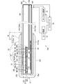
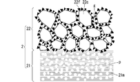
- FIG. 2 is a schematic diagram of a configuration of a gas sensor 100 including a cross-sectional view along a longitudinal direction of a sensor element 10. It is a figure which shows the detailed structure of the inner side protective layer 21 and the outer side protective layer 22 typically.
- FIG. 4 is a diagram for describing an effect of an outer protective layer 22.
- FIG. 4 is a diagram showing a flow of processing when manufacturing the sensor element 10.
- FIG. 1 is a schematic external perspective view of a sensor element (gas sensor element) 10 as one mode of a ceramic structure having a surface structure according to an embodiment of the present invention.
- a ceramic structure refers to a structure having ceramics as a main constituent material while having components other than ceramic components (for example, electrodes and wiring made of metal) inside and on the surface.
- FIG. 2 is a schematic diagram of the configuration of the gas sensor 100 including a cross-sectional view along the longitudinal direction of the sensor element 10.
- the sensor element 10 is a main component of the gas sensor 100 that detects a predetermined gas component in the gas to be measured and measures the concentration.
- the sensor element 10 is a so-called limiting current type gas sensor element.
- the gas sensor 100 mainly includes a pump cell power supply 30, a heater power supply 40, and a controller 50 in addition to the sensor element 10.
- the sensor element 10 generally has a configuration in which one end side of a long plate-shaped element base 1 is covered with a porous tip protection layer 2.
- the element substrate 1 has a long plate-shaped ceramic body 101 as a main structure, and includes a main surface protection layer 170 on two main surfaces of the ceramic body 101.
- the tip protection layer 2 is provided on the end face on one tip side (the tip face 101e of the ceramic body 101) and outside the four side faces.
- four side surfaces excluding both end surfaces in the longitudinal direction of the sensor element 10 (or the element substrate 1 and the ceramic body 101) are simply referred to as side surfaces of the sensor element 10 (or the element substrate 1 and the ceramic body 101). .
- the ceramic body 101 is made of a ceramic mainly composed of zirconia (yttrium-stabilized zirconia) which is an oxygen ion conductive solid electrolyte.
- Various components of the sensor element 10 are provided outside and inside the ceramic body 101.
- the ceramic body 101 having such a configuration is dense and airtight.
- the configuration of the sensor element 10 shown in FIG. 2 is merely an example, and the specific configuration of the sensor element 10 is not limited to this.
- the sensor element 10 shown in FIG. 2 has a first internal space 102, a second internal space 103, and a third internal space 104 inside a ceramic body 101. It is. That is, in the sensor element 10, the first internal cavity 102 is a gas that opens to the outside on the one end E1 side of the ceramic body 101 (strictly speaking, communicates with the outside via the tip protection layer 2).
- the inlet 105 communicates with the first diffusion control part 110 and the second diffusion control part 120, and the second internal space 103 communicates with the first internal space 102 through the third diffusion control part 130.
- the third internal chamber 104 communicates with the second internal chamber 103 through the fourth diffusion controlling section 140.
- a path from the gas inlet 105 to the third internal space 104 is also referred to as a gas circulation unit.
- a flow portion is provided in a straight line along the longitudinal direction of the ceramic body 101.
- the first diffusion control part 110, the second diffusion control part 120, the third diffusion control part 130, and the fourth diffusion control part 140 are all provided as upper and lower two slits in the drawing.
- the first diffusion control part 110, the second diffusion control part 120, the third diffusion control part 130, and the fourth diffusion control part 140 apply a predetermined diffusion resistance to the gas to be measured passing therethrough.
- a buffer space 115 having an effect of buffering the pulsation of the gas to be measured is provided between the first diffusion control section 110 and the second diffusion control section 120.
- the outer surface of the ceramic body 101 is provided with an external pump electrode 141, and the first internal chamber 102 is provided with an internal pump electrode 142. Further, the second internal chamber 103 is provided with an auxiliary pump electrode 143, and the third internal chamber 104 is provided with a measurement electrode 145 which is a direct detection unit of the gas component to be measured.
- a reference gas inlet 106 through which the reference gas is introduced to the outside and a reference electrode 147 is provided in the reference gas inlet 106. Have been.
- the NOx gas concentration in the gas to be measured is calculated by the following process.
- the gas to be measured introduced into the first internal space 102 is adjusted to have a substantially constant oxygen concentration by the pumping action of the main pump cell P1 (pumping or pumping out oxygen), and then the second internal gas is discharged. It is introduced into the empty room 103.
- the main pump cell P1 is an electrochemical pump cell composed of an external pump electrode 141, an internal pump electrode 142, and a ceramic layer 101a which is a part of the ceramic body 101 present between the two electrodes.
- oxygen in the gas to be measured is pumped out of the element by the pumping action of the auxiliary pump cell P2, which is also an electrochemical pump cell, and the gas to be measured is sufficiently low in oxygen.
- a partial pressure state is set.
- the auxiliary pump cell P2 includes an external pump electrode 141, an auxiliary pump electrode 143, and a ceramic layer 101b that is a portion of the ceramic body 101 existing between the two electrodes.
- the external pump electrode 141, the internal pump electrode 142, and the auxiliary pump electrode 143 are formed as porous cermet electrodes (for example, a cermet electrode of Pt containing 1% Au and ZrO 2 ).
- the internal pump electrode 142 and the auxiliary pump electrode 143 that are in contact with the gas to be measured are formed using a material that has reduced or no reduction ability for NOx components in the gas to be measured.
- the measurement electrode 145 is a porous cermet electrode that also functions as a NOx reduction catalyst that reduces NOx existing in the atmosphere in the third internal space 104. During such reduction or decomposition, the potential difference between the measurement electrode 145 and the reference electrode 147 is kept constant. Then, oxygen ions generated by the above-described reduction or decomposition are pumped out of the element by the measurement pump cell P3.
- the measurement pump cell P3 includes an external pump electrode 141, a measurement electrode 145, and a ceramic layer 101c which is a portion of the ceramic body 101 present between the electrodes.
- the measurement pump cell P3 is an electrochemical pump cell that pumps out oxygen generated by the decomposition of NOx in the atmosphere around the measurement electrode 145.
- Pumping (pumping or pumping out oxygen) in the main pump cell P1, the auxiliary pump cell P2, and the measuring pump cell P3 is performed between the electrodes provided in each pump cell by the pump cell power supply (variable power supply) 30 under the control of the controller 50.
- This is realized by applying a voltage required for In the case of the measurement pump cell P3, a voltage is applied between the external pump electrode 141 and the measurement electrode 145 such that the potential difference between the measurement electrode 145 and the reference electrode 147 is maintained at a predetermined value.
- the pump cell power supply 30 is usually provided for each pump cell.
- the controller 50 detects a pump current Ip2 flowing between the measurement electrode 145 and the external pump electrode 141 according to the amount of oxygen pumped by the measurement pump cell P3, and detects a current value (NOx signal) of the pump current Ip2 and The NOx concentration in the measured gas is calculated based on the fact that there is a linear relationship with the concentration of the decomposed NOx.
- the gas sensor 100 includes a plurality of electrochemical sensor cells (not shown) that detect a potential difference between each pump electrode and the reference electrode 147, and control of each pump cell by the controller 50 This is performed based on the detection signal of the sensor cell.
- the heater 150 is embedded inside the ceramic body 101.
- the heater 150 is provided on the lower side of the gas flow unit in the drawing in FIG.
- the heater 150 is provided for the main purpose of heating the sensor element 10 in order to increase the oxygen ion conductivity of the solid electrolyte constituting the ceramic body 101 when the sensor element 10 is used. More specifically, the heater 150 is provided so that its periphery is surrounded by the insulating layer 151.
- the heater 150 is a resistance heating element made of, for example, platinum or the like.
- the heater 150 generates heat by power supply from the heater power supply 40 under the control of the controller 50.
- the sensor element 10 is heated by the heater 150 such that the temperature at least in the range from the first internal chamber 102 to the second internal chamber 103 becomes 500 ° C. or higher.
- the entire gas flow section from the gas inlet 105 to the third internal space 104 may be heated so as to be 500 ° C. or higher. These are for enhancing the oxygen ion conductivity of the solid electrolyte constituting each pump cell so that the performance of each pump cell is suitably exhibited.
- the temperature in the vicinity of the first internal vacancy 102 which is the highest, is about 700 ° C. to 800 ° C.
- the outer surface of the sensor element 10 having the main surface is referred to as a pump surface, and the main surface on the side provided with the heater 150 (or the outer surface of the sensor element 10 having the main surface), which is located below in FIG. It may be called.
- the pump surface is a main surface closer to the gas inlet 105 than the heater 150, the three internal cavities, and each pump cell
- the heater surface is the gas inlet 105, the three internal vacancies, And a main surface closer to the heater 150 than each pump cell.
- Electrode terminals 160 for establishing electrical connection between the sensor element 10 and the outside are formed. These electrode terminals 160 are provided in a predetermined correspondence relationship with the above-described five electrodes, both ends of the heater 150, and a lead wire for heater resistance detection (not shown) through lead wires (not shown) provided inside the ceramic body 101. It is electrically connected. Therefore, application of a voltage from the pump cell power supply 30 to each pump cell of the sensor element 10 and heating of the heater 150 by power supply from the heater power supply 40 are performed through the electrode terminals 160.
- the above-described main surface protection layers 170 (170 a, 170 b) are provided on the pump surface and the heater surface of the ceramic body 101.
- the main surface protection layer 170 is a layer made of alumina, having a thickness of about 5 ⁇ m to 30 ⁇ m, and having pores with a porosity of about 20% to 40%. It is provided for the purpose of preventing foreign substances and poisoning substances from adhering to the heater surface) and the external pump electrode 141 provided on the pump surface side. Therefore, the main surface protection layer 170a on the pump surface side also functions as a pump electrode protection layer for protecting the external pump electrode 141.
- the porosity is determined by applying a known image processing method (such as binarization processing) to an SEM (scanning electron microscope) image of the evaluation object.
- a known image processing method such as binarization processing
- SEM scanning electron microscope
- a main surface protection layer 170 is provided over substantially the entire surface of the pump surface and the heater surface except for exposing a part of the electrode terminal 160.
- the main surface protection layer 170 may be provided so as to be unevenly distributed near the external pump electrode 141 on the one end E1 side.
- the tip protection layer 2 is provided on the outermost peripheral portion within a predetermined range from the one end E ⁇ b> 1 side of the element substrate 1 having the above-described configuration.
- the tip protection layer 2 is provided with a thickness of 100 ⁇ m or more and 1000 ⁇ m or less.
- the tip protection layer 2 is provided by enclosing a portion of the element substrate 1 that is at a high temperature (about 700 ° C. to 800 ° C. at the maximum) when the gas sensor 100 is used, thereby ensuring water resistance in the portion. This is to suppress the occurrence of cracks (wet cracks) in the element substrate 1 due to a thermal shock caused by a local temperature drop caused by direct water exposure of the part.
- the tip protection layer 2 is provided to prevent poisoning substances such as Mg from entering the inside of the sensor element 10 and to secure poisoning resistance.
- the tip protection layer 2 includes an inner tip protection layer (inner protection layer) 21 and an outer tip protection layer (outer protection layer) 22.
- FIG. 3 is a diagram schematically illustrating a detailed configuration of the inner protective layer 21 and the outer protective layer 22.
- the inner protective layer 21 is provided outside the tip surface 101e on the one end portion E1 side of the element base 1 and the four side surfaces (on the outer periphery on the one end portion E1 side of the element base 1).
- FIG. 2 shows a portion 21a on the pump surface side, a portion 21b on the heater surface side, and a portion 21c on the distal end surface 101e side of the inner protective layer 21.
- the inner protective layer 21 includes an aggregate made of ceramics having a particle diameter of 1.0 ⁇ m to 10 ⁇ m and a binder made of ceramics having a particle diameter of 0.01 ⁇ m to 1.0 ⁇ m. Is a porous layer having a thickness of 50 ⁇ m to 950 ⁇ m, in which a large number of fine spherical pores p are dispersed in a matrix 21 m composed of The porosity is between 20% and 85%. Such a configuration is realized by a forming method described later.
- the particle diameter is a measured value of the circumcircle of the primary particle that can be visually confirmed in the SEM image of the evaluation object (however, the number of measurement points n is 100 or more).
- the particle diameter is determined based on an image obtained by FE-SEM (field emission scanning electron microscope) or AFM (atomic force microscope). It may be a specific mode.
- the size (pore diameter) of the pores p is 0.25 ⁇ m to 5.0 ⁇ m, and the neck diameter of the aggregate is 2.0 ⁇ m or less. These are appropriately adjusted by adjusting the particle diameter of the pore former used for forming the inner protective layer 21.
- the pore diameter is a measured value of a circumcircle of a primary particle that can be visually confirmed in an SEM image or an FE-SEM image of an evaluation object (however, the number of measurement points n is 100 or more). .
- the inner protective layer 21 is strengthened by uniformly dispersing the fine pores p. You. Further, since the heat transfer path is miniaturized and the thermal conductivity is reduced, the inner protective layer 21 is further improved in heat insulation. Such high heat insulation has the effect of further improving the water resistance of the sensor element 10. For example, even when there is no difference in the configuration of the outer protective layer 22, the sensor element 10 in which the pore diameter of the inner protective layer 21 is 5.0 ⁇ m or less is more suitable for the sensor element 10 in which the pore diameter exceeds 5.0 ⁇ m. More excellent water resistance.
- Examples of the material of the aggregate include oxides that are chemically stable in high-temperature exhaust gas such as alumina, spinel, titania, zirconia, magnesia, mullite, and cordierite. It may be a mixture of a plurality of oxides.
- oxides that are chemically stable in high-temperature exhaust gas such as alumina, spinel, titania, zirconia, magnesia, mullite, cordierite and the like are exemplified. It may be a mixture of a plurality of oxides.
- the inner protective layer 21 also has a role as a base layer when the outer protective layer 22 is formed on the element substrate 1. From such a viewpoint, the inner protective layer 21 may be formed on each side surface of the element substrate 1 at least in a range surrounded by the outer protective layer 22.
- the outer protective layer 22 is provided in a thickness of 50 ⁇ m to 950 ⁇ m on the outermost peripheral portion within a predetermined range from the one end E1 of the element substrate 1. In the case shown in FIG. 2, the outer protective layer 22 is provided so as to cover the entire inner protective layer 21 provided on the one end portion E1 side (of the ceramic body 101) of the element substrate 1 from the outside.
- the outer protective layer 22 has a configuration in which a large number of coarse particles 22c around which a large number of fine projections made of fine particles 22f are discretely formed are connected directly or via the fine particles 22f. Having. Such a configuration is realized by a forming method described later.
- the particle size of the coarse particles 22c is 5.0 ⁇ m to 40 ⁇ m, and the particle size of the fine particles 22f is 10 nm or more and 1.0 ⁇ m or less.
- the weight ratio (coarse particles / fine particles) of the coarse particles 22c to the fine particles 22f is 3 to 35.
- the size of the projection (the height from the surface of the coarse particles 22c) is at the nano level of 1.0 ⁇ m at the maximum, and is preferably 500 nm or less.
- the average interval between the projections is about 100 nm to 1000 nm.
- Examples of the material of the coarse particles 22c include oxides chemically stable in high-temperature exhaust gas such as alumina, spinel, titania, zirconia, magnesia, mullite, and cordierite. It may be a mixture of a plurality of oxides.
- oxides that are chemically stable in high-temperature exhaust gas such as alumina, spinel, titania, zirconia, magnesia, mullite, and cordierite are exemplified. It may be a mixture of a plurality of oxides.
- the outer protective layer 22 configured in consideration of these requirements should allow a gas arriving from the outside to pass through a gap g appropriately formed between particles (mostly between convex portions formed of the fine particles 22f). And has properties as a porous layer.
- the porosity of the outer protective layer 22 is preferably 5% to 50%. Furthermore, the porosity of the outer protective layer 22 is preferably smaller than the porosity of the inner protective layer 21.
- a so-called anchor effect acts between the outer protective layer 22 and the inner protective layer 21 as a base layer. Due to the effect of the anchor effect, in the sensor element 10, the outer protective layer 22 may be separated from the element substrate 1 due to a difference in thermal expansion coefficient between the outer protective layer 22 and the element substrate 1 during use. Is more suitably suppressed.
- the outer protective layer 22 has a hierarchical structure of a micro structure and a nano structure in which a number of fine protrusions are provided by the fine particles 22f around the coarse particles 22c. It has a high water repellency.
- FIG. 4 is a diagram for explaining the Lotus effect in the outer protective layer 22.
- FIG. 4A shows a case where a water droplet dp having a size of about several ⁇ m adheres to the surface of the outer protective layer 22 according to the present embodiment
- FIG. 4B shows a conventional sensor element. This figure shows a case where a similar water droplet dp adheres to the surface of a layer formed of only the coarse particles 22c having a size on the order of ⁇ m.
- the water droplet dp comes into contact with the nano-sized convex portion mainly composed of the fine particles 22f, whereas in the latter case, the water droplet dp comes into contact with the coarse particle 22c. Since the former contact angle is larger than the latter contact angle, in the latter case, the water droplet dp is easily broken without maintaining its shape, whereas in the former case, the surface tension of the water droplet dp is maintained. You. That is, the shape of the water droplet dp is maintained. In other words, the surface of the outer protective layer 22 shown in FIG. 4A has excellent water repellency. On the other hand, the conventional configuration shown in FIG. 4B is not preferable because the water repellency is poor and the water derived from the broken water droplet dp easily enters the inside.
- the provision of the water repellency suitably suppresses the intrusion of moisture into the element from the outer protective layer 22 through the gap g. That is, the sensor element 10 according to the present embodiment is less susceptible to water breakage and is superior in water resistance as compared with the related art.
- the inner protective layer 21 When the porosity of the inner protective layer 21 is larger than the porosity of the outer protective layer 22, the inner protective layer 21 has higher heat insulating properties than the outer protective layer 22 and the main surface protective layer 170. This also contributes to improving the water resistance of the sensor element 10.
- FIG. 5 is a diagram showing a flow of processing when the sensor element 10 is manufactured.
- Step S1 When manufacturing the element substrate 1, first, a plurality of blank sheets (not shown) which are green sheets having no pattern and containing an oxygen ion conductive solid electrolyte such as zirconia as a ceramic component are prepared ( Step S1).
- the blank sheet is provided with a plurality of sheet holes used for positioning during printing and lamination.
- a sheet hole is formed in advance in a blank sheet stage prior to pattern formation, for example, by punching using a punching device.
- a through portion corresponding to the internal space is also provided in advance by a similar punching process or the like.
- the thicknesses of the respective blank sheets need not be all the same, and the thicknesses may be different depending on respective corresponding portions in the finally formed element substrate 1.
- step S2 pattern printing and drying are performed on each blank sheet (step S2). Specifically, patterns of various electrodes, patterns of the heater 150 and the insulating layer 151, patterns of the electrode terminals 160, patterns of the main surface protection layer 170, and patterns of internal wiring (not shown) are included. It is formed. In addition, at the timing of the pattern printing, a sublimable material for forming the first diffusion control part 110, the second diffusion control part 120, the third diffusion control part 130, and the fourth diffusion control part 140 ( The application or arrangement of the vanishing material is also performed.
- each pattern is performed by applying a pattern forming paste prepared according to the characteristics required for each forming object to a blank sheet using a known screen printing technique.
- Known drying means can be used for the drying treatment after printing.
- step S3 printing and drying processing of an adhesive paste for laminating and bonding the green sheets is performed.
- a known screen printing technique can be used for printing the bonding paste, and a known drying unit can be used for the drying process after printing.
- the green sheets to which the adhesive has been applied are stacked in a predetermined order and pressed under given temperature and pressure conditions to perform a pressure bonding process to form a single laminated body (step S4).
- the green sheets to be laminated are stacked and held in a predetermined laminating jig (not shown) while positioning the green sheets with sheet holes, and heated and pressed together with the laminating jig by a laminating machine such as a known hydraulic press machine.
- a laminating machine such as a known hydraulic press machine.
- step S5 When the laminated body is obtained as described above, subsequently, a plurality of portions of the laminated body are cut, and each is cut into a unit body that finally becomes an individual element substrate 1 (step S5).
- the obtained unit body is fired at a firing temperature of about 1300 ° C. to 1500 ° C. (step S6).
- the element substrate 1 is manufactured. That is, the element substrate 1 is formed by integrally firing the ceramic body 101 made of a solid electrolyte, each electrode, and the main surface protection layer 170. By integrally firing in this manner, each electrode of the element substrate 1 has a sufficient adhesion strength.
- the tip protection layer 2 is formed on the element substrate 1.
- the tip protection layer 2 is formed by applying a slurry for the inner protection layer prepared in advance to the formation target position of the inner protection layer 21 on the element substrate 1 (step S7), and subsequently, preparing a slurry for the outer protection layer also prepared in advance. This is performed by applying the slurry to the formation target position of the outer protective layer 22 on the element substrate 1 (Step S8), and then firing the element substrate 1 on which the coating film is formed in this manner (Step S9).
- Aggregate (inner protective layer) material and coarse-grained material (outer protective layer) oxide powders that are chemically stable in high temperature exhaust gases such as alumina, spinel, titania, zirconia, magnesia, mullite, cordierite; Binder (inner protective layer) material and particulate material (outer protective layer): oxide powder that is chemically stable in high-temperature exhaust gas such as alumina, spinel, titania, zirconia, magnesia, mullite, cordierite; Porous material (only inner protective layer): Although not particularly specified, a polymer-based pore-forming material, carbon-based powder, or the like can be used.
- Binder (common to both layers): Although not particularly limited, an inorganic binder is preferred from the viewpoint of improving the strength of the inner protective layer 21 obtained by firing.
- alumina sol, silica sol, titania sol and the like can be used;
- Solvent common to both layers: General aqueous and non-aqueous solvents such as water, ethanol, and IPA (isopropyl alcohol) can be used;
- Dispersion material common to both layers: not particularly limited, a material suitable for a solvent may be appropriately added, and examples thereof include polycarboxylic acid (ammonium salt), phosphate ester, and formalin condensed naphthalenesulfonic acid. Available.
- the pore diameter can be adjusted by adjusting the particle diameter of the pore former, and the porosity can be adjusted by adjusting the amount.
- each slurry various methods such as dip coating, spin coating, spray coating, slit die coating, thermal spraying, AD method, and printing method can be applied.
- Slurry viscosity For forming the outer protective layer: 10 mPa ⁇ s to 5000 mPa ⁇ s; For forming the inner protective layer: 500 mPa ⁇ s to 7000 mPa ⁇ s; Pulling speed: 0.1 mm / s to 10 mm / s; Drying temperature: room temperature to 300 ° C; Drying time: 1 minute or more.
- Firing temperature 800 ° C to 1200 ° C; Firing time: 0.5 to 10 hours; Firing atmosphere: air.
- the sensor element 10 obtained by the above-described procedure is housed in a predetermined housing, and is incorporated in a main body (not shown) of the gas sensor 100.
- the outermost layer near the end on the side provided with the gas inlet is provided with a large number of fine projections made of ceramic fine particles around.
- the protective layer By providing a protective layer having a hierarchical structure in which a large number of ceramic coarse particles formed discretely are connected directly or via ceramic fine particles, the protective layer functions as a porous layer, and on the surface thereof, And high water repellency due to the Lotus effect.
- the portion where the hierarchical structure is provided is a portion which is heated to a high temperature (about 700 ° C. to 800 ° C. at the maximum) when the gas sensor is used. Since the hierarchical structure is made of ceramics, the hierarchical structure is used when the gas sensor is used. There is no particular problem caused by the provision of. That is, even when the high-temperature water vapor condenses into water droplets and adheres to the sensor element, the water repellency effectively suppresses the intrusion of water into the sensor element.
- a sensor element having three internal cavities is targeted, but it is not essential that the sensor element has a three-chamber structure. That is, the embodiment in which the outer protective layer of the sensor element is a layer that repels water by the Lotus effect can be applied to a sensor element having two or one internal space.
- baking is performed to form two protective layers at the same time.
- baking is performed once to form the inner protective layer, and then the slurry for forming the outer protective layer is applied and fired to form the outer protective layer. It may be a mode of doing.
- the mode of exhibiting the water repellency based on the Lotus effect is described above.
- the sensor element is not limited to the long-limit sensor element of the limiting current type, regardless of whether or not the water breakage can be a problem. It can be applied to various ceramic sensor elements regardless of whether they are exposed to the outside. As a result, the present invention may be applied not only to the sensor element but also to the outermost layer of a general ceramic structure. Naturally, when the outermost layer of the ceramic structure is generally made of a water-repellent ceramic layer by the Lotus effect, the underlying layer does not need to have a structure as a sensor element.
- the ceramic structure of the present invention that is, a large number of coarse ceramic particles in which a large number of fine projections made of ceramic fine particles are discretely formed on the outermost layer are connected directly or via ceramic fine particles.
- the ceramic structure provided with the protective layer having a hierarchical structure may be used for applications other than the sensor element 10.
- a ceramic structure having the above-described protective layer can be used as a firing setter requiring high thermal shock resistance.
- alumina plate-like particles (average particle diameter: 6 ⁇ m) as an aggregate material and titania fine particles (average particle diameter: 0.25 ⁇ m) as a binder material were used.
- the powder and the powder were weighed so that the weight ratio between the two was 1: 1.
- alumina sol as an inorganic binder acrylic resin as a pore former, and ethanol as a solvent were mixed by a pot mill to obtain a slurry for an inner protective layer.
- the mixing amount of the alumina sol was 10 wt% of the total weight of the alumina powder and the titania powder.
- a spinel powder (average particle diameter of 20 ⁇ m) as coarse particle powder and a magnesia powder (average particle diameter of 0.05 ⁇ m) as fine particle powder were mixed at a weight ratio of both.
- the particles were weighed so that the ratio of the particle powder to the fine particle powder was 20: 1.
- These powders, an alumina sol as an inorganic binder, a polycarboxylate ammonium salt as a dispersant, and water as a solvent were mixed by a self-revolving mixer to obtain a slurry for forming an outer protective layer.
- the mixing amount of the alumina sol was 10 wt% of the total weight of the alumina powder and the titania powder.
- the mixing amount of the ammonium polycarboxylate was 4 wt% of the weight of the fine particle powder.
- the slurry for the inner protective layer prepared in the above-described manner is applied by dip coating to a thickness of 300 ⁇ m on the formation target position of the inner protective layer 21 on the element substrate 1 prepared in advance by a known method. did. Then, it was dried for 1 hour in a dryer set at 200 ° C.
- the slurry for the outer protective layer prepared in the above-described embodiment was applied to the formation target position of the outer protective layer 22 on the element substrate 1 after drying by dip coating to a thickness of 300 ⁇ m. Then, it was dried for 1 hour in a dryer set at 200 ° C.
- composition analysis by EDS (energy dispersive X-ray spectrometer) and XRD (X-ray diffractometer) confirmed that coarse particles 22c were spinel and fine particles 22f were magnesia.
- the sensor element 10 having the hierarchical structure in which the tip protection layer is formed of the outer protection layer and the inner protection layer, and the outer protection layer is composed of micro-level ceramic coarse particles and nano-level ceramic fine particles. It was confirmed that there was.
Landscapes
- Chemical & Material Sciences (AREA)
- Engineering & Computer Science (AREA)
- Ceramic Engineering (AREA)
- Manufacturing & Machinery (AREA)
- Organic Chemistry (AREA)
- Materials Engineering (AREA)
- Structural Engineering (AREA)
- Inorganic Chemistry (AREA)
- Health & Medical Sciences (AREA)
- Life Sciences & Earth Sciences (AREA)
- Chemical Kinetics & Catalysis (AREA)
- General Health & Medical Sciences (AREA)
- Molecular Biology (AREA)
- Electrochemistry (AREA)
- Physics & Mathematics (AREA)
- Analytical Chemistry (AREA)
- Biochemistry (AREA)
- Immunology (AREA)
- General Physics & Mathematics (AREA)
- Pathology (AREA)
- Composite Materials (AREA)
- Medicinal Chemistry (AREA)
- Polymers & Plastics (AREA)
- Measuring Oxygen Concentration In Cells (AREA)
- Porous Artificial Stone Or Porous Ceramic Products (AREA)
Abstract
ガスセンサのセンサ素子が、検知対象ガス成分の検知部を備えたセラミックス構造体である素子基体と、素子基体の最外周部の少なくとも一部に設けられた保護層と、を備え、保護層においては、粒子径が5.0μm~40μmである多数のセラミックス粗粒子の周囲に、粒子径が10nm以上1.0μm以下のセラミックス微粒子からなる大きさが1.0μm以下の多数の凸部が離散的に形成されてなり、個々のセラミックス粗粒子が直接にまたはセラミックス微粒子を介して連接してなり、保護層の気孔率は5%~50%である、ようにした。
Description
本発明は、セラミックス構造体の最外層の構造に関し、特に、内部への水分の浸入の抑制に関する。
従来より、内燃機関からの排ガスなどの被測定ガス中に含まれる所望ガス成分の濃度を知るためのガスセンサとして、ジルコニア(ZrO2)等の酸素イオン伝導性を有する固体電解質からなり、表面や内部にいくつかの電極を備えるセンサ素子を有するものが、広く知られている。係るセンサ素子として、長尺板状の素子形状を有し、かつ、被測定ガスを導入するガス導入口が備わる側の端部に、多孔質体からなる保護層(多孔質保護層)が設けられるものが公知である(例えば、特許文献1および特許文献2参照)。
特許文献1および特許文献2に開示されたセンサ素子の多孔質保護層はいずれも、いわゆる被水割れを防止することを目的として、設けられてなるものである。ここで、被水割れとは、被測定ガス中の水蒸気の凝縮により生じた水滴が高温に加熱された状態のセンサ素子に付着することにより、局所的な温度低下に伴う熱衝撃がセンサ素子に加わり、センサ素子が割れてしまうという現象である。
特許文献1には、水との接触角が75°以上の疎水性耐熱粒子からなる疎水性多孔質保護層(内層)と、水との接触角が30°以下の親水性粒子からなる親水性多孔質保護層(外層)との2層からなる多孔質保護層を設けることで、被水割れを防ぐとともに被測定ガス中に含まれる被毒物質からの保護も実現することを意図したセンサ素子が開示されてなる。
しかしながら、親水性である外層までには水の浸入があるため、センサ素子においては、被水による温度低下が少なからず生じる。
一方、特許文献2には、多孔質拡散抵抗層の外表面上に、常温において親水性を有し、固体電解質体が活性となる高温時において撥水性を有する、表面粗度Raが3.0μm以下の表面保護層を、20μm~150μmの厚みに設けたセンサ素子が開示されている。
係るセンサ素子においては、ライデンフロスト現象により撥水性が発現するようになっているが、耐被水性(被水割れが生じない被水量の上限)はせいぜい20μL程度に留まる。
また、有底円筒状の素子形状を有し、その表面に被毒防止層を設けた酸素センサのセンサ素子も、すでに公知である(例えば、特許文献3参照)。
しかしながら、特許文献3においては、被水割れについて何らの言及はなされてはいない一方で、被毒防止層については、その構成要素の1つであるセラミック粉末の粒度分布(10μm以上50μm以下)と同程度の大きさの空孔を有することが必須の要件とされている。後者によれば、空孔から素子内部に水が浸入してしまうことが懸念される。
さらに、マイクロ構造とナノ構造の組み合わせ(階層構造)によってロータス効果を発現させることにより、高い撥水性が得られることも、すでに公知である(例えば、非特許文献1参照)。
しかしながら、非特許文献1に開示されているのは、ポリマーを用いて階層構造を得る態様であり、セラミックスによる階層構造の形成については、特段の開示はみられない。
"Micro-, nano- and hierarchical structures for superhydrophobicity, self-cleaning and low adhesion", Bharat Bhushan, Yong Chae Jung, Kerstin Koch, Phil. Trans. R. Soc. A (2009) 367, 1631-1672
本発明は、上記課題に鑑みてなされたものであり、例えばガスセンサのセンサ素子のようなセラミックス構造体において、内部への水の浸入を好適に抑制することを、目的とする。
上記課題を解決するため、本発明の第1の態様は、セラミックス構造体であって、最外周部の少なくとも一部が、粒子径が5.0μm~40μmである多数のセラミックス粗粒子の周囲に、粒子径が10nm以上1.0μm以下のセラミックス微粒子からなる大きさが1.0μm以下の多数の凸部が離散的に形成されてなり、個々の前記セラミックス粗粒子が直接にまたは前記セラミックス微粒子を介して連接してなり、気孔率が5%~50%である、第1の多孔質層である、ようにした。
本発明の第2の態様は、第1の態様に係るセラミックス構造体であって、前記セラミックス粗粒子の前記セラミックス微粒子に対する重量比が3~35である、ようにした。
本発明の第3の態様は、第1または第2の態様に係るセラミックス構造体であって、前記第1の多孔質層の内側に、気孔率が20%~85%であってかつ前記第1の多孔質層よりも気孔率が大きい第2の多孔質層を有する、ようにした。
本発明の第4の態様は、第1ないし第3の態様のいずれかに係るセラミックス構造体であって、前記セラミックス粗粒子が、アルミナ、スピネル、チタニア、ジルコニア、マグネシア、ムライト、コージェライトからなる群から選ばれる一以上の酸化物の粒子であり、前記セラミックス微粒子が、アルミナ、スピネル、チタニア、ジルコニア、マグネシア、ムライト、コージェライトからなる群から選ばれる一以上の酸化物の粒子である、ようにした。
本発明の第5の態様は、ガスセンサのセンサ素子であって、測定対象ガス成分の検知部を備えたセラミックス構造体である素子基体と、前記素子基体の最外周部の少なくとも一部に設けられた多孔質層である保護層と、を備え、前記保護層においては、粒子径が5.0μm~40μmである多数のセラミックス粗粒子の周囲に、粒子径が10nm以上1.0μm以下のセラミックス微粒子からなる大きさが1.0μm以下の多数の凸部が離散的に形成されてなり、個々の前記セラミックス粗粒子が直接にまたは前記セラミックス微粒子を介して連接してなり、前記保護層の気孔率は5%~50%である、ようにした。
本発明の第1ないし第4の態様によれば、第1の多孔質層がロータス効果による高い撥水性を具備するので、第1の多孔質層が設けられた箇所において、セラミックス構造体の内部への水の浸入が、好適に抑制される。しかも、第1の多孔質層はセラミックスにて構成されるので、当該セラミックス構造体を高温環境下で使用することも可能である。
また、本発明の第5の態様によれば、保護層がロータス効果による高い撥水性を具備するので、保護層が設けられた箇所において、センサ素子の内部への水の浸入が、好適に抑制される。これにより、ガスセンサの使用時に高温となる部分に保護層を設けるようにすれば、水蒸気が凝縮した水滴が当該部分に付着することがあったとしても、センサ素子における被水割れの発生が、好適に抑制される。
<センサ素子およびガスセンサの概要>
図1は、本発明の実施の形態に係る表面構造を具備するセラミックス構造体の一態様としての、センサ素子(ガスセンサ素子)10の概略的な外観斜視図である。なお、本実施の形態において、セラミックス構造体とは、内部や表面にセラミックス成分以外の構成要素を(例えば金属からなる電極や配線など)を有しつつも、セラミックスを主たる構成材料とする構造体を意味する。
図1は、本発明の実施の形態に係る表面構造を具備するセラミックス構造体の一態様としての、センサ素子(ガスセンサ素子)10の概略的な外観斜視図である。なお、本実施の形態において、セラミックス構造体とは、内部や表面にセラミックス成分以外の構成要素を(例えば金属からなる電極や配線など)を有しつつも、セラミックスを主たる構成材料とする構造体を意味する。
また、図2は、センサ素子10の長手方向に沿った断面図を含むガスセンサ100の構成の概略図である。センサ素子10は、被測定ガス中の所定ガス成分を検知し、その濃度を測定するガスセンサ100の主たる構成要素である。センサ素子10は、いわゆる限界電流型のガスセンサ素子である。
ガスセンサ100は、センサ素子10のほか、ポンプセル電源30と、ヒータ電源40と、コントローラ50とを主として備える。
図1に示すように、センサ素子10は概略、長尺板状の素子基体1の一方端部側が、多孔質の先端保護層2にて被覆された構成を有する。
素子基体1は概略、図2に示すように、長尺板状のセラミックス体101を主たる構造体とするとともに、該セラミックス体101の2つの主面上には主面保護層170を備え、さらに、センサ素子10においては、一先端部側の端面(セラミックス体101の先端面101e)および4つの側面の外側に先端保護層2が設けられてなる。なお、以降においては、センサ素子10(もしくは素子基体1、セラミックス体101)の長手方向における両端面を除く4つの側面を単に、センサ素子10(もしくは素子基体1、セラミックス体101)の側面と称する。
セラミックス体101は、酸素イオン伝導性固体電解質であるジルコニア(イットリウム安定化ジルコニア)を主成分とするセラミックスからなる。また、係るセラミックス体101の外部および内部には、センサ素子10の種々の構成要素が設けられてなる。係る構成を有するセラミックス体101は、緻密かつ気密なものである。なお、図2に示すセンサ素子10の構成はあくまで例示であって、センサ素子10の具体的構成はこれに限られるものではない。
図2に示すセンサ素子10は、セラミックス体101の内部に第一の内部空室102と第二の内部空室103と第三の内部空室104とを有する、いわゆる直列三室構造型のガスセンサ素子である。すなわち、センサ素子10においては概略、第一の内部空室102が、セラミックス体101の一方端部E1側において外部に対し開口する(厳密には先端保護層2を介して外部と連通する)ガス導入口105と第一の拡散律速部110、第二の拡散律速部120を通じて連通しており、第二の内部空室103が第三の拡散律速部130を通じて第一の内部空室102と連通しており、第三の内部空室104が第四の拡散律速部140を通じて第二の内部空室103と連通している。なお、ガス導入口105から第三の内部空室104に至るまでの経路を、ガス流通部とも称する。本実施の形態に係るセンサ素子10においては、係る流通部がセラミックス体101の長手方向に沿って一直線状に設けられてなる。
第一の拡散律速部110、第二の拡散律速部120、第三の拡散律速部130、および第四の拡散律速部140はいずれも、図面視上下2つのスリットとして設けられている。第一の拡散律速部110、第二の拡散律速部120、第三の拡散律速部130、および第四の拡散律速部140は、通過する被測定ガスに対して所定の拡散抵抗を付与する。なお、第一の拡散律速部110と第二の拡散律速部120の間には、被測定ガスの脈動を緩衝する効果を有する緩衝空間115が設けられている。
また、セラミックス体101の外面には外部ポンプ電極141が備わり、第一の内部空室102には内部ポンプ電極142が備わっている。さらには、第二の内部空室103には補助ポンプ電極143が備わり、第三の内部空室104には、測定対象ガス成分の直接の検知部である測定電極145が備わっている。加えて、セラミックス体101の他方端部E2側には、外部に連通し基準ガスが導入される基準ガス導入口106が備わっており、該基準ガス導入口106内には、基準電極147が設けられている。
例えば、係るセンサ素子10の測定対象が被測定ガス中のNOxである場合であれば、以下のようなプロセスによって、被測定ガス中のNOxガス濃度が算出される。
まず、第一の内部空室102に導入された被測定ガスは、主ポンプセルP1のポンピング作用(酸素の汲み入れ或いは汲み出し)によって、酸素濃度が略一定に調整されたうえで、第二の内部空室103に導入される。主ポンプセルP1は、外部ポンプ電極141と、内部ポンプ電極142と、両電極の間に存在するセラミックス体101の部分であるセラミックス層101aとによって構成される電気化学的ポンプセルである。第二の内部空室103においては、同じく電気化学的ポンプセルである、補助ポンプセルP2のポンピング作用により、被測定ガス中の酸素が素子外部へと汲み出されて、被測定ガスが十分な低酸素分圧状態とされる。補助ポンプセルP2は、外部ポンプ電極141と、補助ポンプ電極143と、両電極の間に存在するセラミックス体101の部分であるセラミックス層101bとによって構成される。
外部ポンプ電極141、内部ポンプ電極142、および補助ポンプ電極143は、多孔質サーメット電極(例えば、Auを1%含むPtとZrO2とのサーメット電極)として形成されてなる。なお、被測定ガスに接触する内部ポンプ電極142および補助ポンプ電極143は、被測定ガス中のNOx成分に対する還元能力を弱めた、あるいは、還元能力のない材料を用いて形成される。
補助ポンプセルによって低酸素分圧状態とされた被測定ガス中のNOxは、第三の内部空室104に導入され、第三の内部空室104に設けられた測定電極145において還元ないし分解される。測定電極145は、第三の内部空室104内の雰囲気中に存在するNOxを還元するNOx還元触媒としても機能する多孔質サーメット電極である。係る還元ないし分解の際には、測定電極145と基準電極147との間の電位差が、一定に保たれている。そして、上述の還元ないし分解によって生じた酸素イオンが、測定用ポンプセルP3によって素子外部へと汲み出される。測定用ポンプセルP3は、外部ポンプ電極141と、測定電極145と、両電極の間に存在するセラミックス体101の部分であるセラミックス層101cとによって構成される。測定用ポンプセルP3は、測定電極145の周囲の雰囲気中におけるNOxの分解によって生じた酸素を汲み出す電気化学的ポンプセルである。
主ポンプセルP1、補助ポンプセルP2、および測定用ポンプセルP3におけるポンピング(酸素の汲み入れ或いは汲み出し)は、コントローラ50による制御のもと、ポンプセル電源(可変電源)30によって各ポンプセルに備わる電極の間にポンピングに必要な電圧が印加されることにより、実現される。測定用ポンプセルP3の場合であれば、測定電極145と基準電極147との間の電位差が所定の値に保たれるように、外部ポンプ電極141と測定電極145との間に電圧が印加される。ポンプセル電源30は通常、各ポンプセル毎に設けられる。
コントローラ50は、測定用ポンプセルP3により汲み出される酸素の量に応じて測定電極145と外部ポンプ電極141との間を流れるポンプ電流Ip2を検出し、このポンプ電流Ip2の電流値(NOx信号)と、分解されたNOxの濃度との間に線型関係があることに基づいて、被測定ガス中のNOx濃度を算出する。
なお、好ましくは、ガスセンサ100は、それぞれのポンプ電極と基準電極147との間の電位差を検知する、図示しない複数の電気化学的センサセルを備えており、コントローラ50による各ポンプセルの制御は、それらのセンサセルの検出信号に基づいて行われる。
また、センサ素子10においては、セラミックス体101の内部にヒータ150が埋設されている。ヒータ150は、ガス流通部の図2における図面視下方側において、一方端部E1近傍から少なくとも測定電極145および基準電極147の形成位置までの範囲にわたって設けられる。ヒータ150は、センサ素子10の使用時に、セラミックス体101を構成する固体電解質の酸素イオン伝導性を高めるべく、センサ素子10を加熱することを主たる目的として、設けられてなる。より詳細には、ヒータ150はその周囲を絶縁層151に囲繞される態様にて設けられてなる。
ヒータ150は、例えば白金などからなる抵抗発熱体である。ヒータ150は、コントローラ50による制御のもと、ヒータ電源40からの給電により発熱する。
本実施の形態に係るセンサ素子10はその使用時、ヒータ150によって、少なくとも第一の内部空室102から第二の内部空室103に至る範囲の温度が500℃以上となるように、加熱される。さらには、ガス導入口105から第三の内部空室104に至るまでのガス流通部全体が500℃以上となるように、加熱される場合もある。これらは、各ポンプセルを構成する固体電解質の酸素イオン伝導性を高め、各ポンプセルの能力が好適に発揮されるようにするためである。係る場合、最も高温となる第一の内部空室102付近の温度は、700℃~800℃程度となる。
以降においては、セラミックス体101の2つの主面のうち、図2において図面視上方側に位置する、主に主ポンプセルP1、補助ポンプセルP2、および測定用ポンプセルP3が備わる側の主面(あるいは当該主面が備わるセンサ素子10の外面)をポンプ面と称し、図2において図面視下方に位置する、ヒータ150が備わる側の主面(あるいは当該主面が備わるセンサ素子10の外面)をヒータ面と称することがある。換言すれば、ポンプ面は、ヒータ150よりもガス導入口105、3つの内部空室、および各ポンプセルに近接する側の主面であり、ヒータ面はガス導入口105、3つの内部空室、および各ポンプセルよりもヒータ150に近接する側の主面である。
セラミックス体101のそれぞれの主面上の他方端部E2側には、センサ素子10と外部との間の電気的接続を図るための複数の電極端子160が形成されてなる。これらの電極端子160は、セラミックス体101の内部に備わる図示しないリード線を通じて、上述した5つの電極と、ヒータ150の両端と、図示しないヒータ抵抗検出用のリード線と、所定の対応関係にて電気的に接続されている。よって、センサ素子10の各ポンプセルに対するポンプセル電源30から電圧の印加や、ヒータ電源40からの給電によるヒータ150の加熱は、電極端子160を通じてなされる。
さらに、センサ素子10においては、セラミックス体101のポンプ面およびヒータ面に、上述した主面保護層170(170a、170b)が備わっている。主面保護層170は、アルミナからなる、厚みが5μm~30μm程度であり、かつ20%~40%程度の気孔率にて気孔が存在する層であり、セラミックス体101の主面(ポンプ面およびヒータ面)や、ポンプ面側に備わる外部ポンプ電極141に対する、異物や被毒物質の付着を防ぐ目的で設けられてなる。それゆえ、ポンプ面側の主面保護層170aは、外部ポンプ電極141を保護するポンプ電極保護層としても機能するものである。
なお、本実施の形態において、気孔率は、評価対象物のSEM(走査電子顕微鏡)像に対し公知の画像処理手法(二値化処理など)を適用することで求めるものとする。
図2においては、電極端子160の一部を露出させるほかはポンプ面およびヒータ面の略全面にわたって主面保護層170が設けられてなるが、これはあくまで例示であり、図2に示す場合よりも、主面保護層170は、一方端部E1側の外部ポンプ電極141近傍に偏在させて設けられてもよい。
<先端保護層の詳細>
センサ素子10においては、上述のような構成を有する素子基体1の一方端部E1側から所定範囲の最外周部に、先端保護層2が設けられてなる。先端保護層2は、100μm以上1000μm以下の厚みに設けられる。
センサ素子10においては、上述のような構成を有する素子基体1の一方端部E1側から所定範囲の最外周部に、先端保護層2が設けられてなる。先端保護層2は、100μm以上1000μm以下の厚みに設けられる。
先端保護層2を設けるのは、素子基体1のうちガスセンサ100の使用時に高温(最高で700℃~800℃程度)となる部分を囲繞することによって、当該部分における耐被水性を確保し、当該部分が直接に被水することによる局所的な温度低下に起因した熱衝撃により素子基体1にクラック(被水割れ)が生じることを、抑制するためである。
加えて、先端保護層2は、センサ素子10の内部にMgなどの被毒物質が入り込むことを防ぐ、耐被毒性の確保のためにも、設けられてなる。
図2に示すように、本実施の形態に係るセンサ素子10においては、先端保護層2が、内側先端保護層(内側保護層)21と外側先端保護層(外側保護層)22から構成される。図3は、内側保護層21と外側保護層22の詳細な構成を模式的に示す図である。
内側保護層21は、素子基体1の一先端部E1側の先端面101eと4つの側面との外側に(素子基体1の一先端部E1側の外周に)設けられてなる。図2においては、内側保護層21のうち、ポンプ面側の部分21aとヒータ面側の部分21bと先端面101e側の部分21cとを示している。
内側保護層21は概略、図3に示すように、粒子径が1.0μm~10μmのセラミックスからなる骨材と、粒子径が0.01μm~1.0μmのセラミックスからなる結着材とを含んで構成されるマトリックス21m中に、多数の微細な球状の気孔pが分散した構成を有する、厚みが50μm~950μmである多孔質層である。気孔率は20%~85%である。係る構成は、後述する形成手法により実現される。
なお、本明細書において、粒子径は、評価対象物のSEM像において目視で確認できる1次粒子の外接円の測定値とする(ただし、測定点数nは100以上とする)。ただし、一般的なSEMによる撮像結果において1次粒子を視認できない場合には、FE-SEM(電界放出型走査電子顕微鏡)やAFM(原子間力顕微鏡)により得られる像に基づいて、粒子径を特定する態様であってもよい。
より詳細には、気孔pのサイズ(気孔径)は0.25μm~5.0μmであり、骨材のネック径は2.0μm以下である。これらは、内側保護層21の形成に際して用いる造孔材の粒子径を調整することで、適宜に調整される。なお、本明細書において、気孔径は、評価対象物のSEM像またはFE-SEM像において目視で確認できる1次粒子の外接円の測定値とする(ただし、測定点数nは100以上とする)。
本実施の形態のように、気孔率を20%~85%に保ちつつ気孔径を5.0μm以下とした場合、微細な気孔pが均一に分散することによって内側保護層21は高強度化される。また、伝熱経路が微細化されて熱伝導率が低下するので、内側保護層21においてはさらに、高断熱化も実現される。そして、係る高断熱化は、センサ素子10の耐被水性をより向上させる効果がある。例えば、外側保護層22の構成に差異がない場合であっても、内側保護層21の気孔径が5.0μm以下であるセンサ素子10の方が、気孔径が5.0μmを超えるセンサ素子10よりも、優れた耐被水性を有する。
骨材の材質としては、アルミナ、スピネル、チタニア、ジルコニア、マグネシア、ムライト、コージェライト等の高温の排ガス中で化学的に安定な酸化物が例示される。複数の酸化物の混合物であってもよい。
結着材の材質についても、アルミナ、スピネル、チタニア、ジルコニア、マグネシア、ムライト、コージェライト等の高温の排ガス中で化学的に安定な酸化物が例示される。複数の酸化物の混合物であってもよい。
内側保護層21は、外側保護層22を素子基体1に対し形成する際の下地層としての役割も有する。係る観点からは、内側保護層21は、素子基体1の各側面の、少なくとも外側保護層22により囲繞される範囲に、形成されればよい。
外側保護層22は、素子基体1の一方端部E1側から所定範囲の最外周部に、50μm~950μmの厚みに設けられてなる。図2に示す場合においては、外側保護層22は、素子基体1の(セラミックス体101の)の一先端部E1側に備わる内側保護層21の全体を、外側から覆うように設けられる。
外側保護層22は、図3に示すように、周囲に微粒子22fからなる多数の微細な凸部が離散的に形成された多数の粗粒子22cが、直接にまたは微粒子22fを介して連接した構成を有する。係る構成は、後述する形成手法により実現される。
粗粒子22cの粒子径は5.0μm~40μmであり、微粒子22fの粒子径は10nm以上1.0μm以下である。また、粗粒子22cの微粒子22fに対する重量比(粗粒子/微粒子)は3~35である。加えて、凸部の大きさ(粗粒子22cの表面からの高さ)は最大でも1.0μmのナノレベルであり、好ましくは500nm以下である。また、凸部同士の平均間隔は100nm~1000nm程度である。
粗粒子22cの材質としては、アルミナ、スピネル、チタニア、ジルコニア、マグネシア、ムライト、コージェライト等の高温の排ガス中で化学的に安定な酸化物が例示される。複数の酸化物の混合物であってもよい。
微粒子22fの材質についても、アルミナ、スピネル、チタニア、ジルコニア、マグネシア、ムライト、コージェライト等の高温の排ガス中で化学的に安定な酸化物が例示される。複数の酸化物の混合物であってもよい。
これらの要件をみたして構成される外側保護層22は、外部から到達したガスについては粒子間(大部分は微粒子22fからなる凸部の間)に適度に形成された間隙gを通過させることが可能な、多孔質層としての性質を有する。
係る場合の外側保護層22の気孔率は、5%~50%であるのが好ましい。さらには、内側保護層21の気孔率よりも外側保護層22の気孔率の方が小さいことが好ましい。係る場合、外側保護層22と下地層たる内側保護層21との間に、いわゆるアンカー効果が作用する。係るアンカー効果が作用することにより、センサ素子10においては、その使用時に外側保護層22と素子基体1との熱膨張率の差に起因して外側保護層22が素子基体1から剥離することが、より好適に抑制される。
加えて、外側保護層22においては、粗粒子22cの周囲に微粒子22fによる多数の微細な凸部が備わる、マイクロ構造とナノ構造との階層構造を有することで、いわゆるロータス効果により、層表面が高い撥水性を奏するようになっている。
図4は、外側保護層22におけるロータス効果について説明するための図である。図4(a)は、本実施の形態に係る外側保護層22の表面に数μm程度の大きさの水滴dpが付着した場合を示しており、図4(b)は、従来のセンサ素子が具備するような、μmオーダーのサイズを有する粗粒子22cのみにて形成された層の表面に、同様の水滴dpが付着した場合を示している。
両者を対比すると、前者の場合、水滴dpは主に微粒子22fからなるナノサイズの凸部と接するのに対し、後者の場合、水滴dpは粗粒子22cと接することになる。前者の接触角の方が後者の接触角より大きいことから、後者の場合、水滴dpがその形状を保てずに破壊しやすいのに対し、前者の場合は、水滴dpの表面張力は維持される。すなわち、水滴dpの形状は保たれる。換言すれば、図4(a)に示す外側保護層22の表面は優れた撥水性を具備してなる。これに対し、図4(b)に示す従来の構成は、撥水性が悪く、破壊された水滴dpに由来する水分が内部に侵入しやすくなっており、好ましくない。
それゆえ、本実施の形態に係るセンサ素子10においては、係る撥水性の具備により、水分が外側保護層22から間隙gを通じて素子内部に浸入することが、好適に抑制される。すなわち、本実施の形態に係るセンサ素子10は、従来に比して、被水割れが生じにくい、耐被水性の点で優れたものとなっている。
なお、内側保護層21の気孔率が外側保護層22の気孔率より大きい場合、内側保護層21は、外側保護層22や主面保護層170に比して高い断熱性を有することとなる。このことも、センサ素子10の耐被水性の向上に資するものとなっている。
<センサ素子の製造プロセス>
次に、上述のような構成および特徴を有するセンサ素子10を製造するプロセスの一例について説明する。図5は、センサ素子10を作製する際の処理の流れを示す図である。
次に、上述のような構成および特徴を有するセンサ素子10を製造するプロセスの一例について説明する。図5は、センサ素子10を作製する際の処理の流れを示す図である。
素子基体1の作製に際しては、まず、ジルコニアなどの酸素イオン伝導性固体電解質をセラミックス成分として含み、かつ、パターンが形成されていないグリーンシートであるブランクシート(図示省略)を、複数枚用意する(ステップS1)。
ブランクシートには、印刷時や積層時の位置決めに用いる複数のシート穴が設けられている。係るシート穴は、パターン形成に先立つブランクシートの段階で、パンチング装置による打ち抜き処理などで、あらかじめ形成されている。なお、セラミックス体101の対応する部分に内部空間が形成されることになるグリーンシートの場合、該内部空間に対応する貫通部も、同様の打ち抜き処理などによってあらかじめ設けられる。また、それぞれのブランクシートの厚みは、全て同じである必要はなく、最終的に形成される素子基体1におけるそれぞれの対応部分に応じて、厚みが違えられていてもよい。
各層に対応したブランクシートが用意できると、それぞれのブランクシートに対してパターン印刷・乾燥処理を行う(ステップS2)。具体的には、各種電極のパターンや、ヒータ150および絶縁層151のパターンや、電極端子160のパターンや、主面保護層170のパターンや、図示を省略している内部配線のパターンなどが、形成される。また、係るパターン印刷のタイミングで、第一の拡散律速部110、第二の拡散律速部120、第三の拡散律速部130、および第四の拡散律速部140を形成するための昇華性材料(消失材)の塗布あるいは配置も併せてなされる。
各々のパターンの印刷は、それぞれの形成対象に要求される特性に応じて用意したパターン形成用ペーストを、公知のスクリーン印刷技術を利用してブランクシートに塗布することにより行う。印刷後の乾燥処理についても、公知の乾燥手段を利用可能である。
各ブランクシートに対するパターン印刷が終わると、グリーンシート同士を積層・接着するための接着用ペーストの印刷・乾燥処理を行う(ステップS3)。接着用ペーストの印刷には、公知のスクリーン印刷技術を利用可能であり、印刷後の乾燥処理についても、公知の乾燥手段を利用可能である。
続いて、接着剤が塗布されたグリーンシートを所定の順序に積み重ねて、所定の温度・圧力条件を与えることで圧着させ、一の積層体とする圧着処理を行う(ステップS4)。具体的には、図示しない所定の積層治具に積層対象となるグリーンシートをシート穴により位置決めしつつ積み重ねて保持し、公知の油圧プレス機などの積層機によって積層治具ごと加熱・加圧することによって行う。加熱・加圧を行う圧力・温度・時間については、用いる積層機にも依存するものであるが、良好な積層が実現できるよう、適宜の条件が定められればよい。
上述のようにして積層体が得られると、続いて、係る積層体の複数個所を切断して、それぞれが最終的に個々の素子基体1となる単位体に切り出す(ステップS5)。
続いて、得られた単位体を、1300℃~1500℃程度の焼成温度で焼成する(ステップS6)。これにより、素子基体1が作製される。すなわち、素子基体1は、固体電解質からなるセラミックス体101と、各電極と、主面保護層170とが、一体焼成されることによって、生成されるものである。なお、係る態様にて一体焼成がなされることで、素子基体1においては、各電極が十分な密着強度を有するものとなっている。
以上の態様にて素子基体1が作製されると、続いて、係る素子基体1に対し、先端保護層2の形成が行われる。先端保護層2の形成は、あらかじめ用意した内側保護層用のスラリーを素子基体1における内側保護層21の形成対象位置に塗布(ステップS7)し、続いて、同じくあらかじめ用意した外側保護層用のスラリーを素子基体1における外側保護層22の形成対象位置に塗布(ステップS8)した後、係る態様にて塗布膜が形成された素子基体1を焼成する(ステップS9)ことによって行われる。
内側保護層形成用のスラリーおよび外側保護層形成用のスラリーの材料は、以下のように例示される。
骨材(内側保護層)材料および粗粒子材料(外側保護層):アルミナ、スピネル、チタニア、ジルコニア、マグネシア、ムライト、コージェライト等の高温の排ガス中で化学的に安定である酸化物粉末;
結着材(内側保護層)材料および微粒子材料(外側保護層):アルミナ、スピネル、チタニア、ジルコニア、マグネシア、ムライト、コージェライト等の高温の排ガス中で化学的に安定である酸化物粉末;
造孔材(内側保護層のみ):特に指定されないが、高分子系造孔材やカーボン系粉末等が使用できる。例えば、アクリル樹脂、メラミン樹脂、ポリエチレン粒子、ポリスチレン粒子、カーボンブラック粉末、黒鉛粉末等が使用可能;
バインダー(両層共通):特に限定されないが、焼成により得られる内側保護層21の強度向上という点からは、無機バインダーが好ましい。例えば、アルミナゾル、シリカゾル、チタニアゾル等が使用可能;
溶媒(両層共通):水、エタノール、IPA(イソプロピルアルコール)などの一般的な水系、非水系の溶媒が使用可能;
分散材(両層共通):特に限定されず、溶媒に適したものを適宜添加すればよく、例えば、ポリカルボン酸系(アンモニウム塩など)、リン酸エステル系、ナフタレンスルホン酸ホルマリン縮合系などが使用可能。
なお、内側保護層21については、造孔材の粒子径を調整することで気孔径を、量を調整することで気孔率を、それぞれに調整可能である。
また、それぞれのスラリーを塗布する手法としては、ディップコート、スピンコート、スプレーコート、スリットダイコート、溶射、AD法、印刷法など、種々の手法を適用可能である。
例えば、ディップコートにより塗布を行う場合であれば、以下の条件が例示される。
スラリーの粘度:
外側保護層形成用:10mPa・s~5000mPa・s;
内側保護層形成用:500mPa・s~7000mPa・s;
引き上げ速度:0.1mm/s~10mm/s;
乾燥温度:室温~300℃;
乾燥時間:1分以上。
外側保護層形成用:10mPa・s~5000mPa・s;
内側保護層形成用:500mPa・s~7000mPa・s;
引き上げ速度:0.1mm/s~10mm/s;
乾燥温度:室温~300℃;
乾燥時間:1分以上。
また、スラリー塗布後に行う焼成の条件は、以下のように例示される。
焼成温度:800℃~1200℃;
焼成時間:0.5時間~10時間;
焼成雰囲気:大気。
焼成時間:0.5時間~10時間;
焼成雰囲気:大気。
上述の手順にて得られたセンサ素子10は、所定のハウジングに収容され、ガスセンサ100の本体(図示せず)に組み込まれる。
以上、説明したように、本実施の形態によれば、ガスセンサのセンサ素子のうち、ガス導入口が備わる側の端部近傍部分の最外層に、周囲にセラミックス微粒子からなる多数の微細な凸部が離散的に形成された多数のセラミックス粗粒子が直接にまたはセラミックス微粒子を介して連接した、階層構造を有する保護層を設けることにより、該保護層を多孔質層として機能させつつ、その表面に、ロータス効果による高い撥水性を具備することができる。係る構成を採用することにより、ガス成分を内部に流入させつつも、内部への水の浸入が好適に抑制されたセンサ素子を実現することが可能となる。
特に、当該階層構造が設けられる部分は、ガスセンサの使用時に高温(最高で700℃~800℃程度)となる部分であるところ、当該階層構造はセラミックスからなるので、ガスセンサの使用に際し、当該階層構造を具備することに起因した特段の支障が生じることはない。すなわち、高温の水蒸気が凝縮して水滴となり、センサ素子に付着した場合であっても、撥水効果により、センサ素子内部への水の浸入は好適に抑制される。
<変形例>
上述の実施の形態においては、3つの内部空室を備えたセンサ素子を対象としているが、センサ素子が3室構造であることは必須ではない。すなわち、センサ素子の外側保護層を、ロータス効果により撥水する層とする態様は、内部空室が2つあるいは1つのセンサ素子にも適用可能である。
上述の実施の形態においては、3つの内部空室を備えたセンサ素子を対象としているが、センサ素子が3室構造であることは必須ではない。すなわち、センサ素子の外側保護層を、ロータス効果により撥水する層とする態様は、内部空室が2つあるいは1つのセンサ素子にも適用可能である。
上述の実施の形態においては、内側保護層形成用のスラリーの塗布と、外側保護層形成用のスラリーの塗布とを行った後に、焼成を行い、2つの保護層を同時に形成しているが、これに代わり、内側保護層形成用のスラリーを塗布した時点でいったん焼成を行って内側保護層を形成したうえで、外側保護層形成用のスラリーを塗布して焼成を行い、外側保護層を形成する態様であってもよい。
また、マイクロレベルのセラミックス粗粒子の周囲にナノレベルのセラミックス微粒子からなる多数の凸部を離散的に設ける階層構造を採用することにより、ロータス効果に基づく撥水性を発現させる態様は、上述した構成の限界電流型の長尺板状のセンサ素子に限らず、また、被水割れが問題となり得るか否かに関わらず、さらには、検知対象ガス成分の検知部が素子の内部に存在するか外部に対し露出して存在するかに関わらず、種々のセラミックス製のセンサ素子に対し適用が可能である。ひいては、センサ素子のみならずセラミックス構造体一般の最外層において、適用されてもよい。当然ながら、セラミックス構造体一般の最外層を、ロータス効果により撥水するセラミックス層とするにあたって、その下地層がセンサ素子としての構造を有している必要はない。
また、本発明のセラミックス構造体、すなわち、最外層に、周囲にセラミックス微粒子からなる多数の微細な凸部が離散的に形成された多数のセラミックス粗粒子が直接にまたはセラミックス微粒子を介して連接した、階層構造を有する保護層を設けたセラミックス構造体は、センサ素子10以外の他の用途に用いられてもよい。例えば、高い耐熱衝撃性が求められる焼成用セッターとして、上記の保護層を有するセラミックス構造体を用いることが可能である。
外側保護層22がマイクロレベルの粗粒子22cとナノレベルの微粒子22fとからなる階層構造を有するセンサ素子10の作製を試みた。
まず、内側保護層用のスラリーを作製するべく、骨材の材料としてのアルミナ板状粒子(平均粒子径6μm)の粉末と、結合材の材料としてのチタニア微粒子(平均粒子径0.25μm)の粉末とを、両者の重量比が粗粒子粉末:微粒子粉末=1:1になるよう秤量した。これらの粉末と、無機バインダーとしてのアルミナゾルと、造孔材としてのアクリル樹脂と、溶媒としてのエタノールとを、ポットミルにより混合し、内側保護層用のスラリーを得た。アルミナゾルの混合量はアルミナ粉末とチタニア粉末との総重量の10wt%とした。
また、外側保護層用のスラリーを作製するべく、粗粒子粉末としてのスピネル粉末(平均粒子径20μm)と、微粒子粉末としてマグネシア粉末(平均粒子径0.05μm)とを、両者の重量比が粗粒子粉末:微粒子粉末=20:1になるよう秤量した。これらの粉末と、無機バインダーとしてのアルミナゾルと、分散剤としてのポリカルボン酸アンモニウム塩と、溶媒としての水とを自公転ミキサーにより混合し、外側保護層形成用のスラリーを得た。アルミナゾルの混合量はアルミナ粉末とチタニア粉末との総重量の10wt%とした。また、ポリカルボン酸アンモニウム塩の混合量は、微粒子粉末の重量の4wt%とした。
上述の態様にて作製した内側保護層用のスラリーを、公知の手法にてあらかじめ作製しておいた素子基体1における内側保護層21の形成対象位置に対し、ディップコートにて300μmの厚みに塗布した。その後、200℃に設定した乾燥機中で、1時間乾燥させた。
次いで、上述の態様にて作製した外側保護層用のスラリーを、係る乾燥後の素子基体1における外側保護層22の形成対象位置に対し、ディップコートにて300μmの厚みに塗布した。その後、200℃に設定した乾燥機中で、1時間乾燥させた。
最後に、大気中において、焼成温度を1100℃として3時間の焼成を行い、内側保護層21と外側保護層22を備えたセンサ素子10を完成させた。
得られたセンサ素子10について、外側保護層22をSEMにより観察したところ、周囲に微粒子22fからなる多数の微細な凸部が離散的に形成された粗粒子22cが、微粒子22fを介して焼結した構成が、確認された。凸部の大きさはおおよそ50nm~500nm程度であり、凸部同士の間隔は100nm~1000nm程度であった。
また、EDS(エネルギー分散型X線分光器)とXRD(X線回折装置)による組成分析により、粗粒子22cがスピネルであり、微粒子22fがマグネシアであることも確認された。
すなわち、先端保護層が外側保護層と内側保護層から構成され、かつ、外側保護層がマイクロレベルのセラミックス粗粒子とナノレベルのセラミックス微粒子とからなる階層構造を有するセンサ素子10につき、作製可能であることが、確認された。
Claims (5)
- セラミックス構造体であって、
最外周部の少なくとも一部が、
粒子径が5.0μm~40μmである多数のセラミックス粗粒子の周囲に、粒子径が10nm以上1.0μm以下のセラミックス微粒子からなる大きさが1.0μm以下の多数の凸部が離散的に形成されてなり、
個々の前記セラミックス粗粒子が直接にまたは前記セラミックス微粒子を介して連接してなり、
気孔率が5%~50%である、
第1の多孔質層である、
ことを特徴とする、セラミックス構造体。 - 請求項1に記載のセラミックス構造体であって、
前記セラミックス粗粒子の前記セラミックス微粒子に対する重量比が3~35である、
ことを特徴とする、セラミックス構造体。 - 請求項1または請求項2に記載のセラミックス構造体であって、
前記第1の多孔質層の内側に、気孔率が20%~85%であってかつ前記第1の多孔質層よりも気孔率が大きい第2の多孔質層を有する、
ことを特徴とする、セラミックス構造体。 - 請求項1ないし請求項3のいずれかに記載のセラミックス構造体であって、
前記セラミックス粗粒子が、アルミナ、スピネル、チタニア、ジルコニア、マグネシア、ムライト、コージェライトからなる群から選ばれる一以上の酸化物の粒子であり、
前記セラミックス微粒子が、アルミナ、スピネル、チタニア、ジルコニア、マグネシア、ムライト、コージェライトからなる群から選ばれる一以上の酸化物の粒子である、
ことを特徴とする、セラミックス構造体。 - ガスセンサのセンサ素子であって、
測定対象ガス成分の検知部を備えたセラミックス構造体である素子基体と、
前記素子基体の最外周部の少なくとも一部に設けられた多孔質層である保護層と、
を備え、
前記保護層においては、
粒子径が5.0μm~40μmである多数のセラミックス粗粒子の周囲に、粒子径が10nm以上1.0μm以下のセラミックス微粒子からなる大きさが1.0μm以下の多数の凸部が離散的に形成されてなり、
個々の前記セラミックス粗粒子が直接にまたは前記セラミックス微粒子を介して連接してなり、
前記保護層の気孔率は5%~50%である、
ことを特徴とする、ガスセンサのセンサ素子。
Priority Applications (5)
| Application Number | Priority Date | Filing Date | Title |
|---|---|---|---|
| JP2020547825A JP7178420B2 (ja) | 2018-09-28 | 2018-09-28 | セラミックス構造体およびガスセンサのセンサ素子 |
| PCT/JP2018/036400 WO2020065952A1 (ja) | 2018-09-28 | 2018-09-28 | セラミックス構造体およびガスセンサのセンサ素子 |
| DE112018007864.7T DE112018007864T5 (de) | 2018-09-28 | 2018-09-28 | Keramikstruktur und Sensorelement für Gassensor |
| CN201880096717.7A CN112739665A (zh) | 2018-09-28 | 2018-09-28 | 陶瓷结构体及气体传感器的传感器元件 |
| US17/183,620 US20210179496A1 (en) | 2018-09-28 | 2021-02-24 | Ceramic structured body and sensor element of gas sensor |
Applications Claiming Priority (1)
| Application Number | Priority Date | Filing Date | Title |
|---|---|---|---|
| PCT/JP2018/036400 WO2020065952A1 (ja) | 2018-09-28 | 2018-09-28 | セラミックス構造体およびガスセンサのセンサ素子 |
Related Child Applications (1)
| Application Number | Title | Priority Date | Filing Date |
|---|---|---|---|
| US17/183,620 Continuation US20210179496A1 (en) | 2018-09-28 | 2021-02-24 | Ceramic structured body and sensor element of gas sensor |
Publications (1)
| Publication Number | Publication Date |
|---|---|
| WO2020065952A1 true WO2020065952A1 (ja) | 2020-04-02 |
Family
ID=69950529
Family Applications (1)
| Application Number | Title | Priority Date | Filing Date |
|---|---|---|---|
| PCT/JP2018/036400 Ceased WO2020065952A1 (ja) | 2018-09-28 | 2018-09-28 | セラミックス構造体およびガスセンサのセンサ素子 |
Country Status (5)
| Country | Link |
|---|---|
| US (1) | US20210179496A1 (ja) |
| JP (1) | JP7178420B2 (ja) |
| CN (1) | CN112739665A (ja) |
| DE (1) | DE112018007864T5 (ja) |
| WO (1) | WO2020065952A1 (ja) |
Cited By (3)
| Publication number | Priority date | Publication date | Assignee | Title |
|---|---|---|---|---|
| JPWO2021124987A1 (ja) * | 2019-12-17 | 2021-06-24 | ||
| CN116008376A (zh) * | 2021-10-22 | 2023-04-25 | 日本碍子株式会社 | 传感器元件 |
| WO2024100954A1 (ja) * | 2022-11-08 | 2024-05-16 | 日本特殊陶業株式会社 | センサ素子、ガスセンサ及びセンサ素子の製造方法 |
Families Citing this family (2)
| Publication number | Priority date | Publication date | Assignee | Title |
|---|---|---|---|---|
| CN119569439B (zh) * | 2025-02-08 | 2025-05-27 | 成都能斯特新材料科技有限公司 | 一种氮氧传感器耐水保护层、氮氧传感器及其制备方法 |
| CN120574064B (zh) * | 2025-08-06 | 2025-11-11 | 浩弛汽车电子系统(长春)有限公司 | 一种氧化铝防水隔热涂层及其制备方法和应用 |
Citations (3)
| Publication number | Priority date | Publication date | Assignee | Title |
|---|---|---|---|---|
| JP2012173147A (ja) * | 2011-02-22 | 2012-09-10 | Ngk Spark Plug Co Ltd | ガスセンサ素子、及びガスセンサ |
| JP2012173146A (ja) * | 2011-02-22 | 2012-09-10 | Ngk Spark Plug Co Ltd | ガスセンサ素子及びガスセンサ |
| JP2017187482A (ja) * | 2016-03-30 | 2017-10-12 | 日本碍子株式会社 | センサ素子及びガスセンサ |
Family Cites Families (7)
| Publication number | Priority date | Publication date | Assignee | Title |
|---|---|---|---|---|
| AU698761B2 (en) * | 1994-06-22 | 1998-11-05 | Mitsubishi Materials Corporation | Magnesia-titania refractory and method for manufacturing the same |
| US6156409A (en) * | 1996-12-09 | 2000-12-05 | Nippon Sheet Glass Co., Ltd. | Non-fogging article and process for the production thereof |
| CN1726127A (zh) * | 2002-12-12 | 2006-01-25 | 密科理股份有限公司 | 多孔烧结复合材料 |
| US7732497B2 (en) | 2007-04-02 | 2010-06-08 | The Clorox Company | Colloidal particles for lotus effect |
| JP5416757B2 (ja) * | 2011-02-22 | 2014-02-12 | 日本特殊陶業株式会社 | ガスセンサ素子及びガスセンサ |
| JP6008739B2 (ja) * | 2012-12-27 | 2016-10-19 | 日揮触媒化成株式会社 | 撥水性透明被膜付基材およびその製造方法 |
| JP6359373B2 (ja) * | 2013-09-05 | 2018-07-18 | 日本特殊陶業株式会社 | ガスセンサ素子及びガスセンサ |
-
2018
- 2018-09-28 WO PCT/JP2018/036400 patent/WO2020065952A1/ja not_active Ceased
- 2018-09-28 DE DE112018007864.7T patent/DE112018007864T5/de not_active Ceased
- 2018-09-28 JP JP2020547825A patent/JP7178420B2/ja not_active Expired - Fee Related
- 2018-09-28 CN CN201880096717.7A patent/CN112739665A/zh active Pending
-
2021
- 2021-02-24 US US17/183,620 patent/US20210179496A1/en not_active Abandoned
Patent Citations (3)
| Publication number | Priority date | Publication date | Assignee | Title |
|---|---|---|---|---|
| JP2012173147A (ja) * | 2011-02-22 | 2012-09-10 | Ngk Spark Plug Co Ltd | ガスセンサ素子、及びガスセンサ |
| JP2012173146A (ja) * | 2011-02-22 | 2012-09-10 | Ngk Spark Plug Co Ltd | ガスセンサ素子及びガスセンサ |
| JP2017187482A (ja) * | 2016-03-30 | 2017-10-12 | 日本碍子株式会社 | センサ素子及びガスセンサ |
Cited By (9)
| Publication number | Priority date | Publication date | Assignee | Title |
|---|---|---|---|---|
| JPWO2021124987A1 (ja) * | 2019-12-17 | 2021-06-24 | ||
| WO2021124987A1 (ja) * | 2019-12-17 | 2021-06-24 | 日本碍子株式会社 | ガスセンサのセンサ素子およびセンサ素子への保護層形成方法 |
| JP7500613B2 (ja) | 2019-12-17 | 2024-06-17 | 日本碍子株式会社 | ガスセンサのセンサ素子およびセンサ素子への保護層形成方法 |
| US12416600B2 (en) | 2019-12-17 | 2025-09-16 | Ngk Insulators, Ltd. | Sensor element of gas sensor and method for forming protective layer of sensor element |
| CN116008376A (zh) * | 2021-10-22 | 2023-04-25 | 日本碍子株式会社 | 传感器元件 |
| JP2023062921A (ja) * | 2021-10-22 | 2023-05-09 | 日本碍子株式会社 | センサ素子 |
| JP7716955B2 (ja) | 2021-10-22 | 2025-08-01 | 日本碍子株式会社 | センサ素子 |
| WO2024100954A1 (ja) * | 2022-11-08 | 2024-05-16 | 日本特殊陶業株式会社 | センサ素子、ガスセンサ及びセンサ素子の製造方法 |
| JP2024068310A (ja) * | 2022-11-08 | 2024-05-20 | 日本特殊陶業株式会社 | センサ素子、ガスセンサ及びセンサ素子の製造方法 |
Also Published As
| Publication number | Publication date |
|---|---|
| US20210179496A1 (en) | 2021-06-17 |
| JPWO2020065952A1 (ja) | 2021-09-02 |
| CN112739665A (zh) | 2021-04-30 |
| DE112018007864T5 (de) | 2021-05-06 |
| JP7178420B2 (ja) | 2022-11-25 |
Similar Documents
| Publication | Publication Date | Title |
|---|---|---|
| JP7178420B2 (ja) | セラミックス構造体およびガスセンサのセンサ素子 | |
| JP6739926B2 (ja) | ガスセンサ素子及びガスセンサ | |
| US8636886B2 (en) | Gas sensor element and method of manufacturing the same | |
| US10996191B2 (en) | Sensor element and gas sensor | |
| US20210156817A1 (en) | Ceramic structured body and sensor element of gas sensor | |
| US12153012B2 (en) | Gas sensor | |
| US12416600B2 (en) | Sensor element of gas sensor and method for forming protective layer of sensor element | |
| WO2020145366A1 (ja) | 複合部材 | |
| US20220252540A1 (en) | Sensor element | |
| JP7227824B2 (ja) | ガスセンサのセンサ素子 | |
| US20210389271A1 (en) | Sensor element of gas sensor | |
| WO2020158338A1 (ja) | 排気センサ | |
| JP7090211B2 (ja) | ガスセンサのセンサ素子 | |
| JP7179968B2 (ja) | ガスセンサのセンサ素子 | |
| JP7194809B2 (ja) | ガスセンサのセンサ素子 | |
| CN108693234B (zh) | 传感器元件 | |
| CN112946044A (zh) | 气体传感器的传感器元件 | |
| JP4107990B2 (ja) | 電気化学素子 | |
| WO2020195692A1 (ja) | ガスセンサのセンサ素子 |
Legal Events
| Date | Code | Title | Description |
|---|---|---|---|
| 121 | Ep: the epo has been informed by wipo that ep was designated in this application |
Ref document number: 18935582 Country of ref document: EP Kind code of ref document: A1 |
|
| ENP | Entry into the national phase |
Ref document number: 2020547825 Country of ref document: JP Kind code of ref document: A |
|
| 122 | Ep: pct application non-entry in european phase |
Ref document number: 18935582 Country of ref document: EP Kind code of ref document: A1 |