WO2020060350A1 - 3차원 맞춤형 골신장술을 위한 골 신장장치, 그 제작방법, 기록매체 및 완전맞춤형 골신장장치 제작장치 - Google Patents
3차원 맞춤형 골신장술을 위한 골 신장장치, 그 제작방법, 기록매체 및 완전맞춤형 골신장장치 제작장치 Download PDFInfo
- Publication number
- WO2020060350A1 WO2020060350A1 PCT/KR2019/012318 KR2019012318W WO2020060350A1 WO 2020060350 A1 WO2020060350 A1 WO 2020060350A1 KR 2019012318 W KR2019012318 W KR 2019012318W WO 2020060350 A1 WO2020060350 A1 WO 2020060350A1
- Authority
- WO
- WIPO (PCT)
- Prior art keywords
- bone
- extension device
- manufacturing
- fixing
- binding
- Prior art date
- Legal status (The legal status is an assumption and is not a legal conclusion. Google has not performed a legal analysis and makes no representation as to the accuracy of the status listed.)
- Ceased
Links
Images




Classifications
-
- A—HUMAN NECESSITIES
- A61—MEDICAL OR VETERINARY SCIENCE; HYGIENE
- A61B—DIAGNOSIS; SURGERY; IDENTIFICATION
- A61B17/00—Surgical instruments, devices or methods
-
- A—HUMAN NECESSITIES
- A61—MEDICAL OR VETERINARY SCIENCE; HYGIENE
- A61B—DIAGNOSIS; SURGERY; IDENTIFICATION
- A61B17/00—Surgical instruments, devices or methods
- A61B17/56—Surgical instruments or methods for treatment of bones or joints; Devices specially adapted therefor
-
- A—HUMAN NECESSITIES
- A61—MEDICAL OR VETERINARY SCIENCE; HYGIENE
- A61B—DIAGNOSIS; SURGERY; IDENTIFICATION
- A61B17/00—Surgical instruments, devices or methods
- A61B17/56—Surgical instruments or methods for treatment of bones or joints; Devices specially adapted therefor
- A61B17/58—Surgical instruments or methods for treatment of bones or joints; Devices specially adapted therefor for osteosynthesis, e.g. bone plates, screws or setting implements
- A61B17/60—Surgical instruments or methods for treatment of bones or joints; Devices specially adapted therefor for osteosynthesis, e.g. bone plates, screws or setting implements for external osteosynthesis, e.g. distractors, contractors
- A61B17/66—Alignment, compression or distraction mechanisms
-
- A—HUMAN NECESSITIES
- A61—MEDICAL OR VETERINARY SCIENCE; HYGIENE
- A61B—DIAGNOSIS; SURGERY; IDENTIFICATION
- A61B17/00—Surgical instruments, devices or methods
- A61B17/56—Surgical instruments or methods for treatment of bones or joints; Devices specially adapted therefor
- A61B17/58—Surgical instruments or methods for treatment of bones or joints; Devices specially adapted therefor for osteosynthesis, e.g. bone plates, screws or setting implements
- A61B17/68—Internal fixation devices, including fasteners and spinal fixators, even if a part thereof projects from the skin
- A61B17/80—Cortical plates, i.e. bone plates; Instruments for holding or positioning cortical plates, or for compressing bones attached to cortical plates
-
- A—HUMAN NECESSITIES
- A61—MEDICAL OR VETERINARY SCIENCE; HYGIENE
- A61B—DIAGNOSIS; SURGERY; IDENTIFICATION
- A61B34/00—Computer-aided surgery; Manipulators or robots specially adapted for use in surgery
- A61B34/10—Computer-aided planning, simulation or modelling of surgical operations
-
- B—PERFORMING OPERATIONS; TRANSPORTING
- B33—ADDITIVE MANUFACTURING TECHNOLOGY
- B33Y—ADDITIVE MANUFACTURING, i.e. MANUFACTURING OF THREE-DIMENSIONAL [3D] OBJECTS BY ADDITIVE DEPOSITION, ADDITIVE AGGLOMERATION OR ADDITIVE LAYERING, e.g. BY 3D PRINTING, STEREOLITHOGRAPHY OR SELECTIVE LASER SINTERING
- B33Y50/00—Data acquisition or data processing for additive manufacturing
- B33Y50/02—Data acquisition or data processing for additive manufacturing for controlling or regulating additive manufacturing processes
Definitions
- the present invention relates to a fully customized bone extension device, a semi-adjustable bone extension device, a manufacturing method thereof, a recording medium, and a fully customized bone extension device, and more specifically, heat-grown to form a small maxilla, mandible bone or human bone tissue. It relates to a fully customized bone extension device capable of fixing a jaw bone extension device in an accurate position with an accurate vector when stretching using a bone nephrology device, a method for manufacturing the same, a recording medium, and a device for manufacturing a fully customized bone extension device.
- bone renal surgery as a surgical treatment for the maxilla and mandible showing the thermal growth.
- This treatment is a method of increasing the length of the mandibular or maxilla of heat-growing mandible and cutting the bone little by little using a kidney device every day.
- the extension direction of the jaw bone is very important, and accordingly, appropriate new bone formation, face shape, and occlusion treatment results are influenced.
- bone renal surgery can be used in various areas for the purpose of increasing the length of human bone tissue as well as the jaw bone.
- Distraction device for jaw bone to increase jaw bone or other bone tissue such as maxilla and mandible can be classified into an external or external or external kidney device and an intraoral or internal kidney device.
- the extraoral extension device is a device that is installed so that the bone extension device is exposed to the outside of the face and is adjusted from the outside. It has advantages such as simplicity of installation, ease of operation, and adjustment of the kidney direction, but it is inconvenient for social life and permanently on the face. There are disadvantages such as the possibility of leaving a phosphorus scar.
- the intraoral extension device is a device in which the bone extension device is mounted in the oral cavity, and has been recently used because of the disadvantages of the external oral device.
- the renal device in the oral cavity has a control portion in the oral cavity, problems such as discomfort in chewing activity and difficulty in adjusting the direction of the kidney may occur.
- the direction of bone extension is almost all determined by the position or angle of the bone extension device determined by the installation of the bone extension device.
- the bone elongation device is a structure including a bone elongation device and a fixing plate for fixing bones to each other to be mounted on a corresponding bone area.
- the fixed plate is a structure that can be bent by the hand of the person performing the surgery, and is bent and bound to a structure corresponding to the surface of the corresponding bone area on which the bone extension device is mounted, so that the bone extension device can be mounted on the corresponding bone area.
- the position or angle of the bone stretching device is determined according to the bending direction and angle of the fixing plate for fixing the bone stretching device.
- the bone stretching device is not mounted in the correct position and in the correct direction, the maxilla or the mandible is stretched to the wrong position, resulting in an abnormal shape of the face, and at the same time, functional problems such as malocclusion.
- the present invention in order to solve the conventional problems as described above, when extending by using a bone renal surgery device for the entire human bone including the small maxilla or mandible by thermal growth, the jaw bone extension device in the correct position with an accurate vector
- An object of the present invention is to provide a fully customizable bone extension device that can be fixed, a manufacturing method thereof, a recording medium, and a fully customized bone extension device.
- a method of manufacturing a fully customized bone extension device is a method of manufacturing a fully customized bone extension device 100, a) a 3D image file of a relevant bone part of a target patient Or an image file generation step of generating a skull 3D image file and a tooth 3D image file; b) a fused image generation step of generating a fused image by fusing a related bone part 3D image file or a skull 3D image and a tooth 3D image; c) a mounting position and direction selection step of cutting the maxilla, mandible, or related bone parts to be operated in the fusion image and selecting a position and direction in which the bone elongation device and the elongation device adhesion fixation are mounted; d) a step of generating an elongation device close-fixed shape to create a shape of an elongated device close-fixed portion consisting of a bone contact portion and an elongation device binding portion after the installation position
- the method of manufacturing the fully customized bone extension device has a structure corresponding to the teeth of the maxilla and the mandible, and the wafer 131 fixed between the maxilla and the mandible, and the adhesion device of the extension device
- a guide for fixing the fastener including a binding unit 132 having a structure to be coupled with the extension unit binding unit 112 of 110, and a connecting unit 133 connecting and integrating the wafer 131 and the binding unit 132
- a guide fixing guide shape generating step of generating a shape of the shape S146
- a contact fixing guide manufacturing step S151 of manufacturing the contact fixing guide using the generated contact fixing guide shape data.
- the contact fixing guide shape generation step (S146) may further include the step of generating a shape corresponding to the bone extension device 120 so as to be coupled to the bone extension device 120 in the binding portion 132. have.
- the step d) the elongation device close-fixed shape generation step is to set the fixed position in the fusion image by fixing the fixed position in contact with the fusion image of the mandibular bone, the maxilla or other bone, the bone, It may be a configuration including; a bolt hole position setting step of setting the bolt hole position to be formed in the contact portion in the fusion image.
- the step d) of the elongation device close-fixation shape generation step may include a surface data extraction step of extracting the surface data of the fusion image corresponding to the outer shape of the bone contact portion including the bolt hole.
- step d) the step of creating a shape for fixing the elongation device for the elongation device creates a bone contact shape for generating a bone contact shape having a thickness based on the surface data of the fusion image corresponding to the outline of the bone contact portion including the bolt hole.
- Step may include.
- the thickness (t) of the bone contact portion may be 1 to 3 mm.
- the d) elongation device close-fixed shape generation step may include a configuration including; elongation device binding portion generating step of generating a shape of the elongation device binding portion that is bound to the bone elongation apparatus.
- step d) elongation device close-fixed shape generation step may be a configuration that includes; a fastening hole generating step of generating a fastening hole shape that can be bolted to the bone stretching device in the stretching device binding portion.
- the e) elongation device adhesion fixation manufacturing step it is possible to manufacture the elongation device adhesion fixation using Rapid Prototyping equipment based on data using CAD / CAM technology.
- the e) elongation device adhesion fixation manufacturing step after manufacturing the elongation device adhesion fixation using Rapid Prototyping equipment based on the data using CAD / CAM technology, the elongation device adhesion through milling machining The fixing part can be completed.
- the present invention can also provide a fully customized bone extension device manufactured by the method for manufacturing a fully customized bone extension device, wherein the fully customized bone extension device according to an aspect of the present invention is accurately applied to a skull or other bone surface.
- a contact surface of a corresponding shape, and one or more bolt holes to be screwed to the skull, a structure that is connected to the bone extension device, and a pair of extension devices arranged to face both sides based on the fracture line of the extension site Close fixation; And a bone stretching device that is tightly coupled with the pair of stretching devices and is fixed to each other.
- the elongation device close-fixed portion has a contact surface having a shape corresponding to a bone surface such as a skull surface, and a structure extended by a predetermined length in a direction corresponding to a position and direction to be mounted of the bone elongation device.
- a pair of bone contact portions arranged to face both sides based on the fracture line of the kidney portion;
- An extension device binding portion having a structure extending from a surface of each of the bone contact portions by a predetermined height, and having a fastening hole capable of bolting with the bone extension device; And a bolt hole formed on each of the bone contact portions and capable of bolting the mandibular bone and the mandibular bone fixation.
- the bone contact portion includes a first bone contact portion and a second bone contact portion disposed to face both sides based on a fracture line of the kidney portion, and an upper surface of the first bone contact portion A first binding portion protruding upward by a predetermined height is formed, and a second binding portion protruding upward by a predetermined height is formed on an upper surface of the second bone contact portion, and the first binding portion and the second binding portion are formed. There may be formed a fastening hole that can be bound with the bone stretching device.
- the fastening holes formed in the first binding portion and the second binding portion may be formed in a direction inclined by an angle of 30 to 60 degrees downward.
- an inclined surface in a direction orthogonal to the formation direction of the fastening hole may be formed on one side surface of the first and second binding parts.
- the bone elongation device is fixed to one of the elongation device adhesion fixing unit, and a first fixing unit for mounting a guide rod having a structure extending by a predetermined length on one side;
- a second fixing unit fixed to the other one of the elongation fixing units and fixedly mounted on a guide rod mounted on the first fixing unit;
- a screw that is integrally mounted with the first and second fixing portions, and adjusts a separation distance between the first and second fixing portions by a rotation operation. It may be configured to include.
- the first fixing portion and the second fixing portion may be formed with a binding hole capable of binding to the elongation device close fixing portion.
- the binding hole may be formed in a direction inclined by an angle of 30 to 60 degrees downward.
- an inclined surface may be formed in a direction parallel to the formation direction of the binding hole on one side of the second fixing part in a direction facing the binding hole of the first fixing part.
- a binding protrusion having a structure protruding by a predetermined length may be formed on one side of each of the first fixing portion and the second fixing portion, which are engaged with the elongation device contact fixing portion.
- the first fixing portion includes a 'c'-shaped structure on a cut surface in a form surrounding the first binding portion of the first bone contact portion, and is bound to the first binding portion by bolting
- the second fixing part may be a structure that is bolted to one side of the second binding portion of the second bone contact portion.
- the second fixing portion includes a 'c'-shaped structure on a cut surface, and the second fixing portion has a through-hole through which a bolt fixed to the second binding portion and fixed to enter can enter. Can be formed.
- a method for manufacturing a bone elongation apparatus includes: a) an image file generation step of generating a 3D image file of a skull and a 3D image file of a tooth of a target patient; b) a fusion image generation step of fusion of a skull 3D image and a tooth 3D image to generate a fusion image; c) a mounting position and direction selection step of cutting the maxilla, mandible or related bone parts to be operated in the fusion image and selecting a position and direction in which the bone elongation device and bone elongation device are to be mounted; d) a bone extension device guide shape generation step of generating a shape of a bone extension device including a contact fixing surface, an extension device binding groove and an extension device binding hole after the installation position and direction selection step; And e) a bone stretching device guide manufacturing step of manufacturing the bone extension device using the generated bone extension device shape data.
- the step of selecting the mounting position and the direction includes: a corrected simulation step of positioning the cut maxilla, mandible or bone tissue in a position to be corrected; A kidney device position and direction selection step of selecting a position and direction of a bone stretching device after performing a calibration simulation step; And a bone extension device guide position and direction selection step for selecting the position and direction of the close contact surface of the bone extension device, the binding device binding groove and the extension device binding hole, so as to correspond to the position and direction of the bone extension device.
- the step d) of the bone extension device guide shape generation step is to set a fixed position on the fusion image in which the contact surface is fixed in contact with the fusion image, and then bind the extension device to be formed in the bone extension device. It may be configured to include; setting the binding hole position to set the hole position in the fusion image (10).
- the d) bone extension device guide shape generation step may be a configuration that includes; surface data extraction step of extracting the surface data of the fusion image corresponding to the outer shape of the contact surface, including the elongation device binding hole.
- the d) bone extension device guide shape generating step is a bone extension device shape for generating a bone extension device shape having a thickness based on the surface data of the fused image corresponding to the outer shape of the contact fixed surface including the elongation device binding hole. It may be configured to include; generating step.
- the thickness (t) of the bone extension device may be 1 to 3 mm.
- the d) bone stretching device guide shape generation step may be configured to include; a stretching device binding unit generating step of generating a stretching device binding groove shape that is engaged with the fixed portion of the stretching device.
- the d) bone extension device guide shape generating step may be a configuration that includes; a discontinuous portion generating step of generating a discontinuous structure of the outer structure of the binding groove of the stretching device so as not to interfere with the connecting portion of the stretching device.
- a bone elongation device guide may be manufactured using Rapid Prototyping equipment based on data using CAD / CAM technology.
- the e) bone elongation device guide manufacturing step after manufacturing a bone elongation device guide using Rapid Prototyping equipment based on data using CAD / CAM technology, and then guide the elongation device guide through milling machining. Can be completed.
- the method for manufacturing the bone elongation apparatus includes a cutting guide shape generation step of generating a cutting guide shape having a plate-like structure at a position corresponding to a cutting line for cutting orthodontic maxilla, mandible or bone tissue. It may be a configuration.
- the present invention can also provide a bone elongation device manufactured by the above manufacturing method.
- an adhesion fixing surface having a shape corresponding to a skull surface is formed on a lower surface.
- a bone extension device guide main body portion having an extension device binding groove having an indented structure corresponding to a fixing part of the extension device on an upper surface;
- an extension device binding hole having a structure extending from the extension device binding groove to the surface of the maxilla in a direction corresponding to the mounting position and direction of the bone extension device.
- a discontinuous structure may be formed on the outer structure of the binding device binding groove so as not to interfere with the connecting portion of the extension device on the upper portion of the bone extension device.
- the bone extension device may be configured to further include a cutting guide having a plate-like structure at a position corresponding to a cutting line for cutting orthodontic maxilla, mandible or bone tissue.
- the present invention can also provide a recording medium storing a program for executing a method for manufacturing a bone extension device in a computer.
- the present invention also, a computer and a monitor for performing a program for executing the manufacturing method on a computer;
- the arithmetic processing unit of the computer is controlled by shape data calculated according to the method of manufacturing the bone extension device, and a 3D printer for manufacturing the bone extension device.
- FIG. 1 is an overall flow chart showing a method of manufacturing a fully customized bone extension device according to an embodiment of the present invention.
- FIG. 2 is a flow chart showing detailed steps of the step of generating the shape of the elongation device tightly fixed in FIG. 1.
- FIG. 3 is a diagram showing a fusion image in which a skull 3D image of a target patient and a 3D image of a tooth area are fused.
- FIG. 4 is a view showing a state in which a cutting line for cutting the mandibular bone in the orthodontic region is set in the fusion image.
- FIG. 5 is a view showing a state in which a fully customized bone extension device according to an embodiment of the present invention is mounted on the mandible shown in FIG. 4.
- FIG. 6 is a view showing a state in which a close fixing part is attached to a corrected portion in a fusion image.
- FIG. 7 is a perspective view showing a fully customized bone extension device according to an embodiment of the present invention.
- FIG. 8 is a perspective view showing an adhesion fixation of the fully customized bone extension device shown in FIG. 7.
- FIG. 9 is a perspective view showing a fully customized bone extension device shown in FIG. 7.
- FIG. 10 is a perspective view showing a state in which a fully customized bone extension device according to another embodiment of the present invention is mounted on a mandibular fusion image.
- FIG. 11 is a view showing a state in which an adhesion fixation of a bone extension device is attached to a bone extension site in a fusion image.
- FIG. 12 is a perspective view showing a fully customized bone extension device illustrated in FIG. 10.
- FIG. 13 is a perspective view showing an adhesion fixation of the fully customized bone extension device illustrated in FIG. 12.
- FIG. 14 is a perspective view showing a state in which the binding bolt is removed from the fully-fitted bone extension device shown in FIG. 12.
- FIG. 15 is a perspective view showing a bone stretching apparatus according to another embodiment of the present invention.
- FIG. 16 is a view showing a state in which a fully-fitted bone extension device according to an embodiment of the present invention is mounted.
- 17 is a view showing a state of fixing the position of the elongation device in close contact using the guide in close contact according to an embodiment of the present invention.
- FIG. 18 is a view showing a state in which the position of the device for fixing the elongation device and the device for fixing the bone is fixed by using the adhesion fixation guide according to another embodiment of the present invention.
- 19 is a diagram illustrating various embodiments of a guide for fixing the adhesive according to another embodiment of the present invention.
- FIG. 20 is an overall flow chart showing a method of manufacturing a bone elongation apparatus bone elongation apparatus guide according to an embodiment of the present invention.
- FIG. 21 is a flowchart showing detailed steps of the mounting position and direction selection step shown in FIG. 20.
- FIG. 22 is a flow chart showing detailed steps of the step of generating the shape of the bone extension device shown in FIG. 20.
- FIG. 23 is a diagram showing a state in which a cutting line for cutting the maxilla, mandible, or bone tissue of the orthodontic region is set in a fusion image in which a 3D image of a skull of a target patient and a 3D image of a tooth are fused.
- 24 is a view showing a state in which the shape of the bone elongation device is generated on the orthodontic site in the fusion image.
- FIG. 25 is a view showing a state in which the bone elongation device is mounted on the bone elongation device generated in FIG. 24.
- 26 is a view showing a state in which the cutting guide according to an embodiment of the present invention is mounted.
- FIG. 27 is a perspective view showing a bone extension device according to an embodiment of the present invention.
- FIG. 28 is a view showing a state in which a bone extension device is mounted on the bone extension device according to an embodiment of the present invention.
- the bone stretching device according to the prior art is mounted in a direction corresponding to the growth direction of the bone at an appropriate position after cutting the mandibular bone of the target patient.
- the bone stretching device according to the prior art has a problem in that the bone stretching device cannot be mounted in the correct position and in the correct direction because it is mounted depending only on the skill level of the operator.
- a method of increasing precision using a skull and jawbone model produced by 3D printing has been used, but it is difficult to consider tooth occlusion, and a method of moving the temporarily installed kidney device to directly install it to the patient Because of this inadequacy, the limits were large.
- the fully customized bone elongation device is a structure including a contact surface of a structure corresponding to the surface of the mandibular bone of the target patient, and can be stably fixed to the surgical site, and can also accurately orient the bone elongation device. Because it performs an important role, the operator can efficiently perform the procedure, thereby shortening the treatment time and improving the accuracy of the procedure.
- the method of manufacturing a fully customized bone extension device according to the present invention is an invention devised according to the recent technological development of rapid prototyping equipment such as computer software and 3D printers, while the conventional manual gypsum model surgery is replaced by digital model surgery. Since the device can be directly positioned, its applicability will be higher.
- an accurate surgical method can be simulated using functions such as 3D movement and rotation on a program. , Based on these simulation results, it is possible to provide a method of manufacturing a fully customized bone extension device that enables an accurate and reliable procedure to be performed.
- FIG. 1 is a flowchart illustrating a method of manufacturing a fully customized bone extension device according to an embodiment of the present invention. It is shown.
- a method of manufacturing a fully customized bone extension device is an image file generation step of generating a 3D image file of a skull and a 3D image file of a tooth of a target patient (S110).
- An image file generation step (S110) of generating a 3D image file of a skull and a 3D image file of a tooth part of a target patient is more specifically a step of generating a 3D image file of a skull and a 3D image file of a tooth part. It can be divided into.
- a process of converting a CT (computed tomography) image of a skull or facial bone is generally performed.
- a 3D scanner is used. It may be necessary to scan the patient's dental gypsum model or to extract the tooth shape data by scanning the 3D scanner by inserting it directly into the oral cavity.
- the next step is to generate a fused image by fusion of the skull 3D image and the tooth 3D image (S120), and these operations can be performed in a general computer aided design / computer aided manufacturing (CAD / CAM) program.
- CAD / CAM computer aided manufacturing
- the next step is to cut the mandible bone 14 to be elongated and moved in the fusion image 10 to the fracture line 15, and then select the position and direction to which the bone extension device 30 and the fully customized bone extension device 100 will be mounted.
- the mounting position selection step (S130) is performed.
- the maxillary bone is cut on the program by drawing the fracture cutting line 21 shown in FIG. 4, and the simulation is performed in a state that can be freely moved to the corrected position. ) Is the step of selecting the location and direction to be mounted.
- the elongation device adhesion fixation shape generation step S140 of generating the shape of the elongation device adhesion fixation 110 made of the bone adhesion part 111 and the extension device binding part 112 is performed.
- this step can also be performed in a computer aided design / computer aided manufacturing (CAD / CAM) program.
- CAD / CAM computer aided manufacturing
- the elongation device adhesion fixation manufacturing step (S150) of manufacturing the elongation device adhesion fixation 110 using the generated elongation device adhesion fixation shape data is performed, wherein the manufacturing of the fully customized bone extension device is rapid prototyping. It can be made in the equipment, preferably a 3-D printer may be used.
- the manufacturing step of the adhesion device for the extension device is produced by using the rapid prototyping equipment based on the data using CAD / CAM technology, and then the adhesion device for the extension device is milled. Can be completed.
- the bone contact portion In the fixing holder shape generation step (S140), as shown in the flow chart of FIG. 2, after setting the fixed position in which the bone contact portion 111 is fixed in contact with the fusion image 10 in the fusion image 10, the bone contact portion
- FIG. 6 shows a state in which the shape of the bone contact portion 111 having a thickness and the shape of the extension device binding portion 112 are generated based on the surface data of the fusion image corresponding to the shape of the adhesion device fixing portion 110.
- the picture is shown.
- a surface data extraction step (S142) of extracting surface data of the fusion image corresponding to the outer shape of the bone contact portion 111 including the bolt hole 114 may be performed.
- the thickness (t) of the bone contact portion 111 may be screwed or bolted to the skull, and there is little interference during maxillofacial surgery and is not particularly limited as long as it has a predetermined stiffness, for example, 1.0 to 3.0 may be mm. More preferably, it may be 1.5 to 2.5 mm.
- a bone contact shape generation step (S143) having a thickness is performed based on the surface data of the fusion image corresponding to the outer shape of the bone contact portion 111 including the bolt hole 114 (S143). You can.
- FIG. 7 is a perspective view showing a fully fit bone extension device according to an embodiment of the present invention
- FIG. 8 is a perspective view showing a close fit of the fully fit bone extension device shown in FIG. 7
- 9 is a perspective view showing a bone stretching device of the fully customized bone stretching device shown in FIG. 7.
- the elongation device contact fixing part 110 has a contact surface having a shape corresponding to the skull surface, and a direction corresponding to the position and direction to be mounted of the bone elongation device 120. It is a structure extended by a predetermined length, and includes a pair of bone contact portions 111 arranged to face both sides based on the fracture line of the kidney.
- the bone contact portion 111 is configured to include a first bone contact portion 111-1 and a second bone contact portion 111-2, which are disposed to face both sides based on the fracture line of the kidney portion. to be.
- a first binding portion 112-1 formed to protrude upward by a predetermined height is formed on an upper surface of the first bone contact portion 111-1, and an upper portion of the second bone contact portion 111-2 is formed.
- a second binding portion 112-2 formed protruding upward by a predetermined height is formed on the surface, and a bone stretching device 120 is provided in the first binding portion 112-1 and the second binding portion 112-2.
- a fastening hole 113 that can be bound with is formed.
- the elongation device contact fixing part 110 is formed by extending a predetermined height from each surface of the bone contact part 111, and a fastening hole that can be bolted with the bone elongation device 120 ( 113) has a stretching device binding portion 112 of the structure is formed.
- a bolt hole 114 capable of bolting the mandibular bone and the mandibular bone fixing portion 111 is formed in each of the bone contact portions 111.
- the fastening holes 113 formed in the first binding portion 112-1 and the second binding portion 112-2 are inclined by an angle of 30 to 60 degrees downward. It can be formed in the direction.
- an inclined surface 115 in a direction orthogonal to the formation direction of the fastening hole 113 may be formed on one side surface of the first binding part 112-1 and the second binding part 112-2. In this case, it is possible to induce bolting fastening more easily when bolting.
- the formation angle of the fastening hole 113 can be appropriately changed according to the intention of the designer or operator.
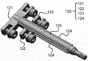
- the bone stretching device 120 includes a first fixing portion 121, a second fixing portion 122 and a screw 123 having a specific structure.
- the first fixing portion 121 is a structure in which a guide rod 124 of a structure fixed to one of the elongating device contact fixing portions 110 and fixed and extended by a predetermined length is mounted on one side.
- the second fixing part 122 is a structure that is fixed to the rest of the elongation device contact fixing part 110 and is mounted to be slidable on the guide rod 124 mounted on the first fixing part 121.
- the screw 123 is mounted integrally with the first fixing part 121 and the second fixing part 122, and between the first fixing part 121 and the second fixing part 122 by a rotation operation. The separation distance can be adjusted.
- the first fixing portion 121 and the second fixing portion 122 there is formed a binding hole 125 that can be engaged with the elongation device close fixing portion 110.
- the binding hole 125 may be formed in a direction inclined by an angle of 30 to 60 degrees downward.
- the inclined surface 127 may be formed in one direction.
- the interference between the bolt or the bolting driver and the second fixing part 122 can be prevented, and a bolting work space can be provided. Bolting efficiency can be improved.
- a predetermined length is applied to one side of each of the first fixing portion 121 and the second fixing portion 122 that are engaged with the elongating device contact fixing portion 110.
- the protrusion 126 of the protruding structure may be formed.
- the first binding portion 112-1 and the second binding portion 112-2 is formed with a binding groove 116 having a structure corresponding to the binding projection 126, ,
- the first fixing portion 121 and the second fixing portion 122 can be stably fixed at a more accurate position.
- the bone stretching apparatus 120 is configured to include a first fixing portion 121 and a second fixing portion 122 having a specific structure.
- the first fixing portion 121 includes a 'c'-shaped structure on a cut surface in a form surrounding the first binding portion 112-1 of the first bone contact portion 111-1. And, it can be bound with the first binding unit 112-1 by bolting.
- the second fixing part 122 is a structure that is bolted to one side of the second binding portion 112-2 of the second bone contact portion 111-2.
- the second fixing portion 122 includes a 'c' shaped structure on the cut surface, the second fixing portion 122, the second binding portion 112-2 and the fixing bolt 128 is to enter A through hole 122-1 that can be formed is formed.
- first binding portion 112-1 may be tied to one side of the first fixing portion 121.
- second binding unit 112-2 may be bound inside the 'c' shaped structure of the second fixing unit 122.
- the first binding portion 112-1 and the second binding portion 112-2 can be selectively bound to a desired portion according to the intention of the operator. You can.
- the structure of the bone stretching device 120 may be changed and applied.
- the screw 123 is embedded inside the bone stretching device 120, and the second fixing part 122 can be configured to change the position along the guide rod 124 by the rotation operation of the screw 123. have.
- the guide rod 124 is preferably mounted in a symmetrical form on both sides of the screw 123, as shown in Figures 15 and 16.
- FIG. 17 and 18 are views showing a state in which the position of the device for fixing the device for fixing the bone and the device for bone extension is fixed by using the guide for fixing the device according to an embodiment of the present invention.
- FIG. 19 is a diagram showing various embodiments of the adhesion fixing guide according to another embodiment of the present invention.
- the adhesion fixing guide 130 is provided with a wafer 131 of a specific structure, a binding portion 132, and connecting portions 133, 134, so that the extension device adhesion fixing portion It can guide the exact position of the bone stretching device.
- the wafer 131 has a structure corresponding to the teeth of the upper and lower teeth and is fixed between the upper and lower teeth.
- the binding portion 132 is a structure in which a structure is formed to be coupled with the extension device binding portion 112 of the extension device contact fixing part 110, and in some cases, the bone extension device 120 to be coupled with the bone extension device 120.
- the connecting portion 133 is configured to connect the wafer 131 and the binding portion 132 to be integrated, and in some cases, separate the structure of the binding portion 132 as shown in FIG. 16. The entire structure can be integrated by adding the connecting portion 134.
- the method for manufacturing the close-fixed guide according to the present embodiment may be carried out in addition to the above-described method for manufacturing a fully customized bone extension device.
- the method for manufacturing a fully customized bone extension device may be a configuration further comprising a contact fixing guide shape generation step (S146) and a contact fixing guide manufacturing step (S151) including a specific configuration. .
- the wafer 131 having a structure corresponding to the teeth of the maxilla and the mandible and fixed between the maxilla and the mandible, the extension device binding portion of the extension device adhesion fixing 110 Generating the shape of the contact fixing guide 130, including a coupling portion 132 having a structure to be coupled with 112, and a connecting portion 133 to connect and integrate the wafer 131 and the binding portion 132 It is a step.
- the adhesion fixing guide manufacturing step (S151) is a step of manufacturing the adhesion fixing guide using the generated adhesion fixing guide shape data.
- adhesion fixing guide manufacturing step (S151) is the same as the above-described configuration of the extension device adhesion fixing manufacturing step (S150) will be omitted below.
- the bone elongation device according to the present invention can serve as a guide capable of fixing the bone elongation device in an accurate position, as shown in FIG. 25, and also serves to accurately orient the bone elongation device. Because it is performed, the operator can efficiently perform the procedure, thereby shortening the treatment time and improving the accuracy of the procedure.
- the method for manufacturing a bone elongation apparatus is an invention devised according to the recent technological development of rapid prototyping equipment such as computer software and a 3D printer, and is a method in which a conventional manual gypsum model surgery is replaced with a digital model surgery. Since it can be fixed directly, the applicability will be higher.
- the present invention can simulate an accurate surgical method using functions such as 3D movement and rotation on a program after cutting a maxilla, mandible or bone tissue to be moved from a fused image in which a skull 3D image and a tooth 3D image are fused.
- FIG. 20 is a flowchart illustrating a method of manufacturing a bone elongation apparatus according to an embodiment of the present invention.
- a method (S100) of manufacturing a bone elongation device includes an image file generation step (S110) of generating a skull 3D image file and a tooth 3D image file of a target patient (S110). And a fusion image generation step (S120) of generating a fusion image 10 by fusion of the 3D image 11 and the 3D image 12 of the teeth.
- An image file generation step (S110) of generating a 3D image file of a skull and a 3D image file of a tooth part of a target patient is more specifically a step of generating a 3D image file of a skull and a 3D image file of a tooth part. It can be divided into.
- a process of converting a CT (computed tomography) image of a skull or facial bone is generally performed.
- a 3D scanner is used. It may be necessary to scan the patient's dental gypsum model or to extract the tooth shape data by scanning the 3D scanner by inserting it directly into the oral cavity.
- the next step is to generate a fused image by fusion of the skull 3D image and the tooth 3D image (S120), and these operations can be performed in a general computer aided design / computer aided manufacturing (CAD / CAM) program.
- CAD / CAM computer aided manufacturing
- Position and direction selection step (S130) is performed.
- the mounting position selection step (S130) of the present invention draws the cutting line 15 shown in FIG. 5 to cut the maxilla, the mandible or the bone tissue on the program, and performs a simulation to put the state in a state that can be freely moved to the corrected position, and extend the bone. This is a step of selecting a location and a direction in which the device 150 and the bone extension device guide 100 will be mounted.
- the bone elongation device shape is generated as the next step as shown in FIG. 22.
- the bone extension device guide shape generation step (S140) for generating the shape of the bone extension device guide 100 including the contact fixing surface 110, the extension device binding groove 120, and the extension device binding hole 130. Is performed. Like the previous step, this step can also be performed in a computer aided design / computer aided manufacturing (CAD / CAM) program.
- CAD / CAM computer aided design / computer aided manufacturing
- the bone extension device guide manufacturing step (S150) of manufacturing the bone extension device guide 100 using the last generated bone extension device guide shape data is performed, wherein the manufacture of the bone extension device can be performed in the Rapid prototyping equipment.
- a 3-D printer may be used.
- the e) bone elongation device guide manufacturing step after manufacturing a bone elongation device guide using Rapid Prototyping equipment based on data using CAD / CAM technology, and then guide the elongation device guide through milling machining. Can be completed.
- the bone extension device In the fixing holder shape generation step (S140), as shown in the flow chart of FIG. 22, after setting the fixed position in which the contact fixing surface 110 is fixed in contact with the fusion image 10 in the fusion image 10, the bone extension device
- the outer portion of the body portion This is the step of extracting the surface data of the fusion image corresponding to the shape.
- FIG. 24 is a view showing a state in which the shape of the bone extension device guide body portion 101 having a thickness is generated based on the surface data of the fused image corresponding to the outer shape of the bone extension apparatus guide body portion 101.
- the thickness (t) of the bone extension device guide body portion 110 may be screwed or bolted to the skull, and has little interference during maxillofacial surgery, and is not particularly limited as long as it has a predetermined stiffness. 1.0 to 3.0 mm. More preferably, it may be 1.5 to 2.5 mm. As shown in FIG.
- the shape of the bone extension device guide 100 having a thickness is based on the surface data of the fused image corresponding to the outer shape of the extension device main body 101 including the extension device binding hole 130.
- the bone stretching device to generate the bone stretching device guide shape generation step (S143) may be performed.
- the stretching device binding unit generating step S144 of generating the shape of the stretching device binding groove 120 that is engaged with the fixing unit 151 of the stretching device 150 may be performed.
- a discontinuity generating step (S145) of generating a discontinuous structure of the outer structure of the stretching device binding groove 120 may be performed so as not to interfere with the connecting portion 152 of the stretching device 150.
- a cutting guide shape generating step (S160) of generating a cutting guide 160 shape of a plate-like structure at a position corresponding to a cutting line cutting a corrected maxilla, mandible or bone tissue is performed. You can.
- the cutting guide 160 is a structure that can be coupled with one side of the bone stretching device 150 fixed to the kidney device bone extension device guide 100, and corresponds to a cutting line that cuts orthodontic maxilla, mandible or bone tissue on one side. It includes a side structure.
- the cutting guide 160 can be manufactured using the shape data obtained through the cutting guide shape generation step (S160), wherein the maxillary, mandible or bone tissue is accurately and stably cut using the manufactured cutting guide 160. can do.
- FIG. 27 is a perspective view showing a bone extension device according to an embodiment of the present invention
- FIG. 26 is a diagram showing a state in which a bone extension device is mounted on the bone extension device according to an embodiment of the present invention. have.
- the bone elongation apparatus guide 100 may be configured to include a bone elongation apparatus guide body portion 101 and a stretching device binding arc 130 having a specific structure.
- the bone extension device guide body portion 101, the contact surface of the shape of the shape corresponding to the skull surface 110 is formed on the lower surface, the height of the stretching device on the upper surface It is a structure in which the elongation device binding groove 120 of the indented structure corresponding to the government 151 is formed.
- extension device binding hole 130 is a structure extending from the extension device binding groove 120 to the surface of the maxilla in a direction corresponding to the mounting position and direction of the bone extension device 150.
- the upper portion of the bone extension device guide 100, the outer structure of the extension device binding groove 120 so as not to interfere with the connecting portion 152 of the extension device 150 In the discontinuous structure 140 may be formed.
- the bone elongation device guide 100 can accurately and stably fix the bone elongation device 150 at a predetermined position and direction.
- the bone extension device guide 100 is provided with a fixed contact surface 110 having a structure corresponding to the outer surface of the maxilla, and is to be stably bound with the bone extension device 150
- the elongation device binding groove 120 of a structure capable of, it is possible to accurately and stably fix the direction and position of the bone elongation device 150.
- the bone elongation device according to the present invention can produce a bone elongation device having a specific structure capable of fixing the bone elongation device in the correct position and direction, significantly improving accuracy compared to the conventional jaw bone renal surgery.
- surgery can be performed quickly and quickly, resulting in shortening of the operation time and achieving significantly improved satisfaction.
- the present invention can also provide a recording medium storing a program for executing a method of manufacturing the bone extension apparatus described above in a computer.
- the present invention is a computer and a monitor for performing a program that executes the above-described method for manufacturing a bone extension device on a computer; And a control processing unit for controlling a 3D printer for manufacturing a bone extension device based on the bone extension device shape data calculated according to the method for manufacturing the bone extension device. .
- the apparatus for manufacturing bone extension devices may be made in rapid prototyping equipment, and a 3-D printer may be preferably used.
- 3D printing may be performed using a metal material, and a bone extension device may be formulated through a casting process after 3D printing using a wax or resin-based material.
- the material constituting the bone extension device is preferably a metal so that it can sufficiently withstand the load applied to the extension device and can be used with a ready-made bone extension device.
- it may be manufactured as a separate structure to form an integrated structure through welding.
- the bone elongation device according to the present embodiment and its manufacturing method can manufacture a bone elongation device having a specific structure capable of fixing the bone elongation device in an accurate position and direction, significantly improving accuracy and reliability compared to a conventional jaw bone extension operation. As well as securing the operation, it is possible to perform the operation quickly and quickly, and as a result, the operation time can be shortened, and the operation result with significantly improved satisfaction can be achieved.
- a fully customized bone extension device As described above, according to the present invention, a fully customized bone extension device, a method of manufacturing the same, a recording medium and a fully customized bone extension device, according to the present invention, a fully customized bone extension is performed by utilizing a skull 3D image and a tooth 3D image of a target patient
- the bone extension device By enabling the device to be manufactured, the bone extension device can be stably fixed at the correct position, and the accuracy of occlusion and reliability of surgery can be secured.
- a fully customized bone extension device according to the present invention, and a method for manufacturing the same, can produce a fully customized bone extension device having a specific structure capable of fixing the extension device to the jaw bone or human bone tissue in an accurate position and direction, and In addition to securing significantly improved accuracy and reliability compared to jaw bone or other bone renal surgery, surgery can be performed quickly and quickly, resulting in shorter surgical time, and significantly improved satisfaction. have.
Landscapes
- Health & Medical Sciences (AREA)
- Surgery (AREA)
- Life Sciences & Earth Sciences (AREA)
- Orthopedic Medicine & Surgery (AREA)
- Engineering & Computer Science (AREA)
- Animal Behavior & Ethology (AREA)
- Public Health (AREA)
- Heart & Thoracic Surgery (AREA)
- Medical Informatics (AREA)
- Molecular Biology (AREA)
- Nuclear Medicine, Radiotherapy & Molecular Imaging (AREA)
- General Health & Medical Sciences (AREA)
- Biomedical Technology (AREA)
- Veterinary Medicine (AREA)
- Chemical & Material Sciences (AREA)
- Manufacturing & Machinery (AREA)
- Materials Engineering (AREA)
- Robotics (AREA)
- Neurology (AREA)
- Surgical Instruments (AREA)
Abstract
완전맞춤형 골신장장치, 반조절성 골신장장치, 그 제작방법, 기록매체 및 완전맞춤형 골신장장치 제작장치가 제시된다. 본 발명의 실시예에 따른 완전맞춤형 골신장장치 제작방법(S100)은, a) 대상 환자의 관련 뼈 부위 3D 이미지 파일 또는 두개골 3D 이미지 파일과 치아부위 3D 이미지 파일을 생성하는 이미지파일 생성단계; b) 관련 뼈 부위 3D 이미지 파일 또는 두개골 3D 이미지와 치아부위 3D 이미지를 융합하여 융합이미지를 생성하는 융합이미지 생성단계; c) 상기 융합이미지에서 수술할 하악골, 혹은 관련 뼈 부위를 절단하고 골 신장장치 및 신장장치 밀착고정부가 장착될 위치 및 방향을 선정하는 장착위치 및 방향 선정단계; d) 상기 장착위치 및 방향 선정단계 이후 골 밀착부 및 신장장치 결속부로 이루어진 신장장치 밀착고정부의 형상을 생성하는 신장장치 밀착고정부 형상 생성단계; 및 e) 생성된 신장장치 밀착고정부 형상데이터를 이용하여 신장장치 밀착고정부를 제조하는 신장장치 밀착고정부 제조단계;를 포함하는 것을 구성의 요지로 한다.
Description
본 발명은 완전맞춤형 골신장장치, 반조절성 골신장장치, 그 제작방법, 기록매체 및 완전맞춤형 골신장장치 제작장치에 관한 것으로, 보다 상세하게는, 열성장하여 작은 상악골, 하악골 또는 인체 골조직을 골 신장술 기구를 이용하여 신장시킬 때, 정확한 백터를 가지고 정확한 위치에 턱뼈신장장치를 고정시킬 수 있는 완전맞춤형 골신장장치, 그 제작방법, 기록매체 및 완전맞춤형 골신장장치 제작장치에 관한 것이다.
악안면 기형 환자 중에서는 상악골 혹은 하악골의 양측 또는 편측이 비정상적으로 열성장을 보이는 경우가 있다. 특히 반안면 왜소증(hemifacial microsomia)이나 입술 입천장 갈림증(구순구개열, cleft lip & palate)과 같은 선천성 기형에 성장 장애가 겹쳐진 경우에 턱뼈의 열성장은 심하게 발생한다.
여러 악안면 기형 중 상기 열성장을 보이는 상악골과 하악골의 외과적 치료법으로서 골신장술이 있다. 이 치료법은 열성장 하악골 혹은 상악골 길이를 증가시킬 목적으로 골절단을 하고 신장장치를 이용하여 매일 조금씩 뼈를 늘려나가는 방법이다. 이때 턱뼈가 늘어나는 신장 방향이 아주 중요하고 이에 따라 적절한 신생골 형성과 얼굴 형태 및 교합 등의 치료 결과가 좌우된다. 그리고 이러한 골신장술은 턱뼈 뿐 아니라 인체 골조직의 길이를 늘리는 목적으로 여러 부위에서 이용할 수 있다.
상악골과 하악골 등 턱뼈나 그외 골조직을 늘리기 위한 골 신장장치(Distraction device for jaw bone)는 구강외 혹은 외부 신장장치와 구강내 혹은 내부 신장장치로 대별할 수 있다. 구강외 신장장치는 골 신장장치가 얼굴 밖으로 노출되게 장착되어 밖에서 조절하도록 이루어진 장치로, 장착의 간단함, 조작의 용이성, 신장 방향 조절 가능 등의 장점이 있으나, 사회생활을 하는데 불편하고 얼굴에 영구적인 흉터를 남길 가능성이 있는 등의 단점이 있다.
한편 구강내 신장장치는 골 신장장치가 구강 내에 장착되는 장치로, 최근 구강외 장치의 단점 때문에 많이 이용되고 있다. 그러나 구강내 신장장치도 조절부분이 구강 내에 있기 때문에 저작 활동의 불편감, 신장 방향 조절의 어려움 등 문제가 발생할 수 있다.
이러한 구강내 신장장치를 이용한 턱뼈 신장술에서 골 신장 방향은 골 신장 장치의 설치에 의해 결정되는 골 신장 장치의 위치나 각도 등에 의해 거의 모두 결정된다.
일반적으로 골 신장장치는 해당 뼈 부위에 장착되기 위해 골 신장장치와 뼈를 서로 고정시키는 고정판을 포함하는 구조이다. 이때 고정판은 수술을 수행하는 자의 손에 의해 구부려질 수 있는 구조로서, 골 신장장치가 장착되는 해당 뼈 부위 표면에 대응되는 구조로 구부려져 결속됨으로써, 골 신장장치를 해당 뼈 부위에 장착시킬 수 있다.
이때, 골 신장장치를 고정시키는 고정판의 구부러지는 방향과 각도 등에 따라 골 신장 장치의 위치나 각도가 결정되게 된다.
따라서, 골 신장장치를 정확한 위치와 정확한 방향으로 장착하지 못할 경우, 상악골이나 하악골이 잘못된 위치로 늘어나면서 얼굴의 형태 이상이 초래되고 동시에 부정교합 등 기능적인 문제가 발생할 수 있다.
따라서, 종래 기술에 따른 신장장치에 대한 문제점을 해결할 수 있는 구성을 포함하는 신장장치 및 이를 제작하는 방법에 관한 기술이 필요한 실정이다.
본 발명은 상기와 같은 종래의 문제점을 해결하기 위하여, 열성장하여 작은 상악골이나 하악골을 포함한 인체 골 전체에 대하여 골 신장술 기구를 이용하여 신장시킬 때, 정확한 백터를 가지고 정확한 위치에 턱뼈신장장치를 고정시킬 수 있는 완전맞춤형 골신장장치, 그 제작방법, 기록매체 및 완전맞춤형 골신장장치 제작장치를 제공하는 데 그 목적이 있다.
상기와 같은 목적을 달성하기 위하여, 본 발명의 일 측면에 따른 완전맞춤형 골신장장치 제작방법은, 완전맞춤형 골신장장치(100)를 제작하는 방법으로서, a) 대상 환자의 관련 뼈 부위 3D 이미지 파일 또는 두개골 3D 이미지 파일과 치아부위 3D 이미지 파일을 생성하는 이미지파일 생성단계; b) 관련 뼈 부위 3D 이미지 파일 또는 두개골 3D 이미지와 치아부위 3D 이미지를 융합하여 융합이미지를 생성하는 융합이미지 생성단계; c) 상기 융합이미지에서 수술할 상악골이나 하악골, 혹은 관련 뼈 부위를 절단하고 골 신장장치 및 신장장치 밀착고정부가 장착될 위치 및 방향을 선정하는 장착위치 및 방향 선정단계; d) 상기 장착위치 및 방향 선정단계 이후 골 밀착부 및 신장장치 결속부로 이루어진 신장장치 밀착고정부의 형상을 생성하는 신장장치 밀착고정부 형상 생성단계; 및 e) 생성된 신장장치 밀착고정부 형상데이터를 이용하여 신장장치 밀착고정부를 제조하는 신장장치 밀착고정부 제조단계;를 포함하는 구성일 수 있다.
본 발명의 일 실시예에 있어서, 상기 완전맞춤형 골신장장치 제작방법은, 상악의 치아 및 하악의 치아와 대응되는 구조를 가지고 상악과 하악 사이에 고정되는 웨이퍼(131), 신장장치 밀착고정부(110)의 신장장치 결속부(112)와 결속되는 구조가 형성된 결속부(132), 및 웨이퍼(131)와 결속부(132)를 연결시켜 일체화 시키는 연결부(133)를 포함하는 밀착고정부 가이드(130)의 형상을 생성하는 밀착고정부 가이드 형상 생성단계(S146); 및 생성된 밀착고정부 가이드 형상데이터를 이용하여 밀착고정부 가이드를 제조하는 밀착고정부 가이드 제조단계(S151);를 더 포함하는 구성일 수 있다.
이 경우, 상기 밀착고정부 가이드 형상 생성단계(S146)는, 결속부(132)에 골 신장장치(120)와 결속되도록 골 신장장치(120)와 대응되는 형상을 생성하는 단계를 더 포함할 수 있다.
본 발명의 일 실시예에 있어서, 상기 d)신장장치 밀착고정부 형상 생성단계는 하악골, 상악골 혹은 다른 골에 대한 골 밀착부가 융합이미지와 접촉하여 고정되는 고정위치를 융합이미지에 설정한 후, 골 밀착부에 형성될 볼트홀 위치를 융합이미지에 설정하는 볼트홀 위치 설정단계;를 포함하는 구성일 수 있다.
이 경우, 상기 d)신장장치 밀착고정부 형상 생성단계는 볼트홀을 포함하는 골 밀착부의 외곽형상에 대응되는 융합이미지의 표면 데이터를 추출하는 표면데이터 추출단계;를 포함할 수 있다.
또한, 상기 d)신장장치 밀착고정부 형상 생성단계는 볼트홀을 포함하는 골 밀착부 외곽형상에 대응되는 융합이미지의 표면 데이터를 바탕으로 두께를 가지는 골 밀착부 형상을 생성하는 골 밀착부 형상 생성단계;를 포함할 수 있다.
이 경우, 상기 골 밀착부의 두께(t)는 1 내지 3 mm 일 수 있다.
본 발명의 일 실시예에 있어서, 상기 d)신장장치 밀착고정부 형상 생성단계는, 골 신장장치와 결속되는 신장장치 결속부 형상을 생성하는 신장장치 결속부 생성단계;를 포함하는 구성일 수 있다.
또한, 상기 d)신장장치 밀착고정부 형상 생성단계는, 신장장치 결속부에 골 신장장치와 볼팅 체결될 수 있는 체결공 형상을 생성하는 체결공 생성단계;를 포함하는 구성일 수 있다.
본 발명의 일 실시예에 있어서, 상기 e)신장장치 밀착고정부 제조단계는, CAD/CAM 기술을 이용한 데이터를 기반으로 Rapid Prototyping 장비를 이용하여 신장장치 밀착고정부를 제작할 수 있다.
경우에 따라서, 상기 e)신장장치 밀착고정부 제조단계는, CAD/CAM 기술을 이용한 데이터를 기반으로 Rapid Prototyping 장비를 이용하여 신장장치 밀착고정부를 제작한 후, 밀링 기계가공을 통하여 신장장치 밀착고정부를 완성할 수 있다.
본 발명은 또한, 상기 완전맞춤형 골신장장치 제작방법에 의해 제작된 완전맞춤형 골신장장치를 제공할 수 있는 바, 본 발명의 일측면에 따른 완전맞춤형 골신장장치는, 두개골 혹은 다른 골 표면에 정확하게 대응되는 형상의 접촉면, 및 두개골에 스크류 고정시킬 수 있도록 하나 이상의 볼트홀을 포함하고, 골 신장장치와 결속되는 구조이며, 신장부위의 골절단선을 기준으로 양측에 마주보도록 배치되는 한 쌍의 신장장치 밀착고정부; 및 상기 한 쌍의 신장장치 밀착고정부와 결속 고정되는 골 신장장치;를 포함하는 구성일 수 있다.
본 발명의 일 실시예에 있어서, 상기 신장장치 밀착고정부는, 두개골 표면 등 골 표면에 대응되는 형상의 접촉면을 가지고, 골 신장장치의 장착될 위치와 방향에 대응하는 방향으로 소정 길이만큼 연장된 구조이며, 신장부위의 골절단선을 기준으로 양측에 마주보도록 배치되는 한 쌍의 골 밀착부; 상기 골 밀착부 각각의 표면으로부터 소정 높이만큼 연장되어 형성되고, 골 신장장치와 볼팅 체결될 수 있는 체결공이 형성된 구조의 신장장치 결속부; 및 상기 골 밀착부 각각에 형성되고, 하악골과 하악골 밀착고정부를 볼팅체결할 수 있는 볼트홀;을 포함하는 구성일 수 있다.
본 발명의 일 실시예에 있어서, 상기 골 밀착부는, 신장부위의 골절단선을 기준으로 양측으로 마주보도록 배치되는 제1골 밀착부 및 제2골 밀착부를 포함하고, 상기 제1골 밀착부의 상부면에는 상방으로 소정 높이만큼 돌출 형성된 제1결속부가 형성되어 있고, 상기 제2골 밀착부의 상부면에는 상방으로 소정 높이만큼 돌출 형성된 제2결속부가 형성되어 있으며, 상기 제1결속부와 제2결속부에는 골 신장장치와 결속될 수 있는 체결공이 형성될 수 있다.
본 발명의 일 실시예에 있어서, 상기 제1결속부와 제2결속부에 형성된 체결공은, 하방으로 30 내지 60도 각도만큼 경사진 방향으로 형성될 수 있다.
이 경우, 상기 제1결속부와 제2결속부의 일측면에는, 체결공의 형성 방향과 직교하는 방향의 경사면이 형성될 수 있다.
본 발명의 일 실시예에 있어서, 상기 골 신장장치는, 상기 신장장치 밀착고정부 중 하나와 결속 고정되고, 일측면에 소정 길이만큼 연장된 구조의 가이드 로드를 장착하는 제1고정부; 상기 신장장치 밀착고정부 중 나머지 하나와 결속 고정되고, 제1고정부에 장착된 가이드 로드에 슬라이딩 구동 가능하도록 장착되는 제2고정부; 및 상기 제1고정부 및 제2고정부와 일체형으로 장착되고, 회전동작에 의해 제1고정부와 제2고정부 사이의 이격거리를 조절하는 스크류; 를 포함하는 구성일 수 있다.
이 경우, 상기 제1고정부와 제2고정부에는, 신장장치 밀착고정부와 결속될 수 있는 결속공이 형성될 수 있다.
또한, 상기 결속공은 하방으로 30 내지 60도 각도만큼 경사진 방향으로 형성될 수 있다.
또한, 상기 제1고정부의 결속공과 마주보는 방향의 제2고정부의 일측면에는, 결속공의 형성방향과 평행한 방향으로 경사면이 형성될 수 있다.
본 발명의 일 실시예에 있어서, 상기 신장장치 밀착고정부와 결속되는 제1고정부와 제2고정부 각각의 일측면에는, 소정길이만큼 돌출된 구조의 결속 돌기가 형성될 수 있다.
본 발명의 일 실시예에 있어서, 상기 제1고정부는, 제1골 밀착부의 제1결속부를 감싸는 형태의 절단면상 'ㄷ'자형 구조를 포함하고, 볼팅 체결에 의해 제1결속부와 결속되며, 상기 제2고정부는, 제2골 밀착부의 제2결속부의 일측면과 볼팅체결되는 구조일 수 있다.
본 발명의 일 실시예에 있어서, 상기 제2고정부는, 절단면상 'ㄷ'자형 구조를 포함하고, 상기 제2고정부에는, 제2결속부와 결속 고정되는 볼트가 진입할 수 있는 관통구가 형성될 수 있다.
상기와 같은 목적을 달성하기 위하여, 본 발명에 따른 골신장장치 제작방법은, a) 대상 환자의 두개골 3D 이미지 파일과 치아부위 3D 이미지 파일을 생성하는 이미지파일 생성단계; b) 두개골 3D 이미지와 치아부위 3D 이미지를 융합하여 융합이미지를 생성하는 융합이미지 생성단계; c) 상기 융합이미지에서 수술할 상악골, 하악골 또는 관련 뼈 부위를 절단하고 골 신장장치 및 골신장장치가 장착될 위치 및 방향을 선정하는 장착위치 및 방향 선정단계; d) 상기 장착위치 및 방향 선정단계 이후 밀착고정면, 신장장치 결속홈 및 신장장치 결속홀을 포함하는 골신장장치의 형상을 생성하는 골신장장치 가이드 형상 생성단계; 및 e) 생성된 골신장장치 형상데이터를 이용하여 골신장장치를 제조하는 골신장장치 가이드 제조단계;를 포함하는 구성일 수 있다.
본 발명의 일 실시예에 있어서, 상기 장착위치 및 방향 선정단계는, 절단된 상악골, 하악골 또는 골조직을 교정 목표로 하는 위치에 위치시키는 교정시뮬레이션 단계; 교정시뮬레이션 단계 수행 후 골 신장장치의 위치 및 방향을 선정하는 신장장치 위치 및 방향 선정단계; 및 골 신장장치의 위치 및 방향에 대응되도록, 골신장장치의 밀착고정면, 신장장치 결속홈 및 신장장치 결속홀의 위치 및 방향을 선정하는 골신장장치 가이드 위치 및 방향 선정단계;를 포함하는 구성일 수 있다.
본 발명의 일 실시예에 있어서, 상기 d)골신장장치 가이드 형상 생성단계는 밀착고정면이 융합이미지와 접촉하여 고정되는 고정위치를 융합이미지에 설정한 후, 골신장장치에 형성될 신장장치 결속홀 위치를 융합이미지(10)에 설정하는 결속홀 위치 설정단계;를 포함하는 구성일 수 있다.
또한, 상기 d)골신장장치 가이드 형상 생성단계는 신장장치 결속홀을 포함하는 밀착고정면의 외곽형상에 대응되는 융합이미지의 표면 데이터를 추출하는 표면데이터 추출단계;를 포함하는 구성일 수 있다.
또한, 상기 d)골신장장치 가이드 형상 생성단계는 신장장치 결속홀을 포함하는 밀착고정면 외곽형상에 대응되는 융합이미지의 표면 데이터를 바탕으로 두께를 가지는 골신장장치 형상을 생성하는 골신장장치 형상 생성단계;를 포함하는 구성일 수 있다.
이때, 상기 골신장장치의 두께(t)는 1 내지 3 mm일 수 있다.
또한, 상기 d)골신장장치 가이드 형상 생성단계는, 신장장치의 고정부와 결속되는 신장장치 결속홈 형상을 생성하는 신장장치 결속부 생성단계;를 포함하는 구성일 수 있다.
또한, 상기 d)골신장장치 가이드 형상 생성단계는, 신장장치의 연결부와 간섭되지 않도록 신장장치 결속홈의 외곽 구조의 불연속 구조를 생성하는 불연속부 생성단계;를 포함하는 구성일 수 있다.
본 발명의 일 실시예에 있어서, 상기 e)골신장장치 가이드 제조단계는, CAD/CAM 기술을 이용한 데이터를 기반으로 Rapid Prototyping 장비를 이용하여 골신장장치 가이드를 제작할 수 있다.
경우에 따라서, 상기 e)골신장장치 가이드 제조단계는, CAD/CAM 기술을 이용한 데이터를 기반으로 Rapid Prototyping 장비를 이용하여 골신장장치 가이드를 제작한 후, 밀링 기계가공을 통하여 골신장장치 가이드를 완성할 수 있다.
본 발명의 일 실시예에 있어서, 상기 골신장장치 제작방법은, 교정 상악골, 하악골 또는 골조직을 절단하는 절단선과 대응되는 위치에 판상형 구조의 절단가이드 형상을 생성하는 절단가이드 형상 생성단계;를 더 포함하는 구성일 수 있다.
본 발명은 또한, 상기 제작방법에 의해 제작된 골신장장치를 제공할 수 있는 바, 본 발명의 일 측면에 따른 골신장장치는, 두개골 표면에 대응되는 형상의 밀착고정면이 하부면에 형성되어 있고, 상부면에 신장장치의 고정부와 대응되는 만입된 구조의 신장장치 결속홈이 형성된 골신장장치 가이드 본체부; 및 상기 골 신장장치의 장착 위치와 방향과 대응되는 방향으로 신장장치 결속홈으로부터 상악골 표면까지 연장된 구조의 신장장치 결속홀;을 포함하는 구성일 수 있다.
본 발명의 일 실시예에 있어서, 상기 골신장장치의 상부에는, 신장장치의 연결부와 간섭되지 않도록 신장장치 결속홈의 외곽 구조에 불연속 구조가 형성될 수 있다.
본 발명의 일 실시예에 있어서, 상기 골신장장치는, 교정 상악골, 하악골 또는 골조직을 절단하는 절단선과 대응되는 위치에 판상형 구조의 절단가이드를 더 포함하는 구성일 수 있다.
본 발명은 또한, 골신장장치 제작방법을 컴퓨터에서 실행시키는 프로그램을 저장한 기록매체를 제공할 수 있다.
본 발명은 또한, 상기 제작방법을 컴퓨터에서 실행시키는 프로그램을 수행하는 컴퓨터와 모니터; 상기 컴퓨터의 산술 처리부에서 상기 골신장장치 제작방법에 따라 산출된 형상 데이터에 의해 제어되어 골신장장치를 제작하는 3차원 프린터;를 포함하는 골 신장장치 골신장장치 가이드 제작장치를 제공할 수 있다.
도 1은 본 발명의 일 실시예에 따른 완전맞춤형 골신장장치 제작방법을 나타내는 전체 흐름도이다.
도 2는 도 1에 나타낸 신장장치 밀착고정부 형상 생성단계를 세부적인 단계로 나타낸 흐름도이다.
도 3은 대상 환자의 두개골 3D 이미지와 치아부위 3D 이미지를 융합한 융합이미지를 나타내는 그림이다.
도 4는 융합이미지에서 교정부위 하악골을 잘라내는 절단선을 설정한 모습을 나타내는 그림이다.
도 5는 도 4에 도시된 하악골에 본 발명의 일 실시예에 따른 완전맞춤형 골신장장치를 장착한 모습을 나타내는 그림이다.
도 6은 융합이미지에서 교정부위에 밀착고정부를 장착한 모습을 나타내는 그림이다.
도 7은 본 발명의 일 실시예에 따른 완전맞춤형 골신장장치를 나타내는 사시도이다.
도 8은 도 7에 도시된 완전맞춤형 골신장장치의 밀착고정부를 나타내는 사시도이다.
도 9는 도 7에 도시된 완전맞춤형 골신장장치를 나타내는 사시도이다.
도 10은 본 발명의 또 다른 실시예에 따른 완전맞춤형 골신장장치를 하악골 융합이지미에 장착한 모습을 나타내는 사시도이다.
도 11은 융합이미지에서 골신장 부위에 골신장 장치의 밀착고정부를 장착한 모습을 나타내는 그림이다.
도 12는 도 10에 도시된 완전맞춤형 골신장장치를 나타내는 사시도이다.
도 13은 도 12에 도시된 완전맞춤형 골신장장치의 밀착고정부를 나타내는 사시도이다.
도 14는 도 12에 도시된 완전맞춤형 골신장장치에서 결속 볼트를 제거한 상태를 나타내는 사시도이다.
도 15는 본 발명의 또 다른 실시예에 따른 골 신장장치를 나타내는 사시도이다.
도 16은 본 발명의 일 실시예에 따른 완전맞춤형 골신장장치를 장착한 모습을 나타내는 그림이다.
도 17은 본 발명의 일 실시예에 따른 밀착고정부 가이드를 이용하여 신장장치 밀착고정부 위치를 고정하는 모습을 나타내는 그림이다.
도 18은 본 발명의 또 다른 실시예에 따른 밀착고정부 가이드를 이용하여 신장장치 밀착고정부 및 골 신장장치의 위치를 고정하는 모습을 나타내는 그림이다.
도 19는 본 발명의 또 다른 실시예에 따른 밀착고정부 가이드의 여러 실시예를 나타내는 그림이다.
도 20은 본 발명의 일 실시예에 따른 골 신장장치 골신장장치 가이드 제작방법을 나타내는 전체 흐름도이다.
도 21은 도 20에 나타낸 장착위치 및 방향 선정단계르 세부적인 단계로 나타낸 흐름도이다.
도 22는 도 20에 나타낸 골신장장치 가이드 형상 생성단계를 세부적인 단계로 나타낸 흐름도이다.
도 23은 대상 환자의 두개골 3D 이미지와 치아부위 3D 이미지를 융합한 융합이미지에 교정부위 상악골, 하악골 또는 골조직을 잘라내는 절단선을 설정한 모습을 나타내는 그림이다.
도 24는 융합이미지에서 교정부위에 골신장장치 형상을 생성한 모습을 나타내는 그림이다.
도 25는 도 24에 생성된 골신장장치에 골 신장장치를 장착한 상태를 나타내는 그림이다.
도 26은 본 발명의 일 실시예에 따른 절단가이드를 장착한 상태를 나타내는 그림이다.
도 27은 본 발명의 일 실시예에 따른 골신장장치를 나타내는 사시도이다.
도 28은 본 발명의 일 실시예에 따른 골신장장치에 골 신장장치를 장착한 상태를 나타내는 그림이다.
이하, 첨부도면을 참조하여 본 발명의 바람직한 실시예를 상세히 설명하지만 본 발명의 범주가 그것에 한정되는 것은 아니다. 본 발명을 설명함에 있어 공지된 구성에 대해서는 그 상세한 설명을 생략하며, 또한 발명의 요지를 불필요하게 흐릴 소지가 있는 구성에 대해서도 그 상세한 설명은 생략하기로 한다.
종래 기술에 따른 뼈 신장장치는 대상 환자의 하악골을 절단한 후 적절한 위치에 골의 성장방향에 대응되는 방향으로 장착된다. 그러나, 종래 기술에 따른 골 신장장치는 수술하는 사람의 숙련도에만 의존하여 장착되기 때문에, 정확한 위치 및 정확한 방향으로 골 신장장치를 장착할 수 없다는 문제점을 가지고 있다. 보다 정확한 시술을 위해 3차원 프린팅으로 제작한 두개골 및 턱뼈 모델을 이용하여 정밀도를 높이는 방안이 사용되어 왔으나, 치아 교합에 대한 고려가 어렵고 여기서 임시 설치한 신장장치를 환자에게 직접 설치하기 위해 이동시키는 방법이 적당하지 못해서 한계가 컸다.
따라서, 시술시 골 신장장치를 상악골에 장착하는 과정에서, 정확한 위치 및 정확한 방향으로 장착하는데 애로가 따르며, 상당한 시간이 소요되고, 정확도 또한 떨어지게 된다.
그러나, 본 발명에 따른 완전맞춤형 골신장장치는 대상 환자의 하악골 표면과 대응되는 구조의 접촉면을 포함하는 구조로서 수술 부위에 안정적으로 고정될 수 있고, 이와 더불어 골 신장장치의 방향을 정확하게 잡아줄 수 있는 역할을 수행하기 때문에 시술자가 효율적으로 시술을 진행할 수 있어 시술 시간을 단축시킬 수 있으며, 시술 정확도 또한 향상시킬 수 있다.
본 발명에 따른 완전맞춤형 골신장장치 제작방법은, 최근의 컴퓨터 소프트웨어 및 3차원 프린터 등의 Rapid Prototyping 장비의 기술 발달에 따라 고안된 발명으로서, 종래의 수작업 석고 모형 수술이 디지털 모형 수술로 대체되는 방식이면서도 장치를 직접 위치 고정시킬 수 있으므로 그 적용 가능성이 더욱 높아질 것이다.
본 발명은 두개골 3차원 이미지와 치아 3차원 이미지를 융합시킨 융합이미지로부터 이동시킬 하악골 등의 부위를 절단시킨 후, 프로그램 상의 3차원 이동, 회전 등의 기능을 이용하여 정확한 수술 방법을 시뮬레이션 할 수 있고, 이러한 시뮬레이션 결과를 바탕으로 정확하고 신뢰성이 높은 시술을 수행할 수 있도록 하는 완전맞춤형 골신장장치 제작방법을 제공할 수 있다.
본 발명에 따른 완전맞춤형 골신장장치 제작방법과 완전맞춤형 골신장장치에 대한 예는 인체 골조직의 여러 부위에서 다양하게 적용할 수 있으며, 이하에서는 첨부된 도면을 기초로 가장 바람직한 실시예에 대해 설명한다.
도 1에는 본 발명의 일 실시예에 따른 완전맞춤형 골신장장치 제작방법을 나타내는 전체 흐름도가 도시되어 있고, 도 2에는 도 1에 나타낸 신장장치 밀착고정부 형상 생성단계를 세부적인 단계로 나타낸 흐름도가 도시되어 있다.
이들 도면을 참조하면, 본 실시예에 따른 완전맞춤형 골신장장치를 제작하는 방법(S100)은, 대상 환자의 두개골 3차원 이미지 파일과 치아부위 3차원 이미지 파일을 생성하는 이미지파일 생성단계(S110), 두개골 3차원 이미지(11)와 치아부위 3차원 이미지(12)를 융합하여 융합이미지(10)를 생성하는 융합이미지 생성단계(S120)를 포함한다.
대상 환자의 두개골 3차원 이미지 파일과 치아부위 3차원 이미지 파일을 생성하는 이미지파일 생성단계(S110)는 보다 구체적으로는 두개골 3차원 이미지 파일을 생성하는 단계와 치아부위 3차원 이미지 파일을 생성하는 단계로 구분될 수 있다.
두개골 3차원 이미지 파일을 생성하는 단계에서는 일반적으로 두개골이나 안면골에 대한 CT(computed tomography, 컴퓨터 단층 촬영) 영상을 변환시키는 과정이 수행되며, 치아부위 3차원 이미지 파일을 생성하는 단계에서는 3차원 스캐너로 환자의 치아 석고 모형을 스캔하거나, 3차원 스캐너를 구강에 직접 삽입하는 방식으로 스캔하여 치아 형상 데이터를 추출하는 과정이 필요할 수 있다.
다음 단계로 두개골 3차원 이미지와 치아부위 3차원 이미지를 융합하여 융합이미지를 생성하는 단계(S120)가 수행되며, 이러한 작업은 일반적인 CAD/CAM(computer aided design / computer aided manufacturing) 프로그램에서 수행될 수 있다.
다음 단계로 융합이미지(10)에서 신장되어 움직일 하악골(14)을 골절단선(15)에 맞춰 자른 뒤 골 신장장치(30) 및 완전맞춤형 골신장장치(100)가 장착될 위치 및 방향을 선정하는 장착위치 선정단계(S130)가 수행된다.
본 발명의 장착위치 선정단계(S130)는 도 4에 나타낸 골절단선(21)을 그어 상악골을 프로그램 상에서 절단하여, 교정 위치로 자유롭게 이동시킬 수 있는 상태로 놓는 시뮬레이션하고, 완전맞춤형 골신장장치(100)가 장착될 위치 및 방향을 선정하는 단계이다.
이후, 골 밀착부(111) 및 신장장치 결속부(112)로 이루어진 신장장치 밀착고정부(110)의 형상을 생성하는 신장장치 밀착고정부 형상 생성단계(S140)가 수행된다. 이전의 단계와 마찬가지로 이 단계도 CAD/CAM(computer aided design / computer aided manufacturing) 프로그램에서 수행될 수 있다.
마지막으로 생성된 신장장치 밀착고정부 형상데이터를 이용하여 신장장치 밀착고정부(110)를 제조하는 신장장치 밀착고정부 제조단계(S150)가 수행되며, 이때 완전맞춤형 골신장장치의 제조는 Rapid prototyping 장비에서 이루어질 수 있으며, 바람직하게는 3-D 프린터가 이용될 수도 있다.
경우에 따라서, 신장장치 밀착고정부 제조단계는, CAD/CAM 기술을 이용한 데이터를 기반으로 Rapid Prototyping 장비를 이용하여 신장장치 밀착고정부를 제작한 후, 밀링 기계가공을 통하여 신장장치 밀착고정부를 완성할 수 있다.
이하에서는 앞서 간략하게 설명된 완전맞춤형 골신장장치의 형상 데이터를 생성하는 고정 홀더형상 생성단계(S140)를 세분화한 도 2의 흐름도와 도 5 내지 도 14를 참조하여 보다 더 상세하게 설명한다.
고정 홀더형상 생성단계(S140)는 도 2의 흐름도에 나타낸 바와 같이 골 밀착부(111)가 융합이미지(10)와 접촉하여 고정되는 고정위치를 융합이미지(10)에 설정한 후, 골 밀착부(111)에 형성될 볼트홀(114) 위치를 융합이미지(10)에 설정하는 볼트홀 위치 설정단계(S141), 볼트홀(114)을 포함하는 골 밀착부(111)의 외곽형상에 대응되는 융합이미지의 표면 데이터를 추출하는 표면데이터 추출단계(S142), 볼트홀(114)을 포함하는 골 밀착부(111) 외곽형상에 대응되는 융합이미지의 표면 데이터를 바탕으로 두께를 가지는 골 밀착부 형상을 생성하는 골 밀착부 형상 생성단계(S143), 골 신장장치(120)와 결속되는 신장장치 결속부(112) 형상을 생성하는 신장장치 결속부 생성단계(S144) 및 신장장치 밀착고정부 형상 생성단계(S140)는, 신장장치 결속부(112)에 골 신장장치(120)와 볼팅 체결될 수 있는 체결공(113) 형상을 생성하는 체결공 생성단계(S145) 중 적어도 하나 이상의 세부 단계를 포함할 수 있다.
또한, 도 6에는 신장장치 밀착고정부(110) 형상에 대응되는 융합이미지의 표면 데이터를 바탕으로 두께를 가지는 골 밀착부(111) 형상 및 신장장치 결속부(112) 형상을 생성한 모습을 나타내는 그림이 도시되어 있다. 도 6에 도시된 바와 같이, 볼트홀(114)을 포함하는 골 밀착부(111)의 외곽형상에 대응되는 융합이미지의 표면 데이터를 추출하는 표면데이터 추출단계(S142)가 수행될 수 있다.
이때, 골 밀착부(111)의 두께(t)는, 두개골에 스크류 또는 볼팅 결합될 수 있고 악안면 수술 시 간섭이 적으며 소정의 강성을 갖는 두께라면 특별히 제한되는 것은 아니며, 예를 들어 1.0 내지 3.0 mm 일 수 있다. 더욱 바람직하게는 1.5 내지 2.5 mm 일 수 있다. 도 6에 도시된 바와 같이, 볼트홀(114)을 포함하는 골 밀착부(111) 외곽형상에 대응되는 융합이미지의 표면 데이터를 바탕으로 두께를 가지는 골 밀착부 형상 생성단계(S143)가 수행될 수 있다.
도 7에는 본 발명의 일 실시예에 따른 완전맞춤형 골신장장치를 나타내는 사시도가 도시되어 있고, 도 8에는 도 7에 도시된 완전맞춤형 골신장장치의 밀착고정부를 나타내는 사시도가 도시되어 있으며, 도 9에는 도 7에 도시된 완전맞춤형 골신장장치의 골 신장장치를 나타내는 사시도가 도시되어 있다.
도 8에 도시된 바와 같이, 본 실시예에 따른 신장장치 밀착고정부(110)는, 두개골 표면에 대응되는 형상의 접촉면을 가지고, 골 신장장치(120)의 장착될 위치와 방향에 대응하는 방향으로 소정 길이만큼 연장된 구조이며, 신장부위의 골절단선을 기준으로 양측에 마주보도록 배치되는 한 쌍 골 밀착부(111)를 포함하고 있다.
구체적으로, 골 밀착부(111)는, 신장부위의 골절단선을 기준으로 양측으로 마주보도록 배치되는 제1골 밀착부(111-1) 및 제2골 밀착부(111-2)를 포함하는 구성이다. 이때, 제1골 밀착부(111-1)의 상부면에는 상방으로 소정 높이만큼 돌출 형성된 제1결속부(112-1)가 형성되어 있고, 상기 제2골 밀착부(111-2)의 상부면에는 상방으로 소정 높이만큼 돌출 형성된 제2결속부(112-2)가 형성되어 있으며, 상기 제1결속부(112-1)와 제2결속부(112-2)에는 골 신장장치(120)와 결속될 수 있는 체결공(113)이 형성되어 있다.
또한, 본 실시예에 따른 신장장치 밀착고정부(110)는, 골 밀착부(111) 각각의 표면으로부터 소정 높이만큼 연장되어 형성되고, 골 신장장치(120)와 볼팅 체결될 수 있는 체결공(113)이 형성된 구조의 신장장치 결속부(112)를 포함하고 있다.
이때, 골 밀착부(111) 각각에는 하악골과 하악골 밀착고정부(111)를 볼팅체결할 수 있는 볼트홀(114)이 형성되어 있다.
경우에 따라서, 도 8에 도시된 바와 같이, 제1결속부(112-1)와 제2결속부(112-2)에 형성된 체결공(113)은, 하방으로 30 내지 60도 각도만큼 경사진 방향으로 형성될 수 있다. 또한, 제1결속부(112-1)와 제2결속부(112-2)의 일측면에는, 체결공(113)의 형성 방향과 직교하는 방향의 경사면(115)이 형성될 수 있다. 이 경우, 볼트 체결 시 볼팅 체결 작업을 더욱 손쉽게 유도할 수 있다. 체결공(113)의 형성 각도는 설계자 또는 시술자의 의도에 따라 적절히 변경 가능함은 물론이다.
도 7 및 도 9에 도시된 바와 같이, 본 실시예에 따른 골 신장장치(120)는 특정 구조의 제1고정부(121), 제2고정부(122) 및 스크류(123)를 포함하는 구성일 수 있다.
구체적으로, 제1고정부(121)는, 신장장치 밀착고정부(110) 중 하나와 결속 고정되고, 일측면에 소정 길이만큼 연장된 구조의 가이드 로드(124)를 장착하는 구조이다.
제2고정부(122)는, 신장장치 밀착고정부(110) 중 나머지 하나와 결속 고정되고, 제1고정부(121)에 장착된 가이드 로드(124)에 슬라이딩 구동 가능하도록 장착되는 구조이다.
또한, 스크류(123)는, 제1고정부(121) 및 제2고정부(122)와 일체형으로 장착되고, 회전동작에 의해 제1고정부(121)와 제2고정부(122) 사이의 이격거리를 조절할 수 있다.
이때, 제1고정부(121)와 제2고정부(122)에는, 신장장치 밀착고정부(110)와 결속될 수 있는 결속공(125)이 형성되어 있다. 경우에 따라서, 결속공(125)은, 하방으로 30 내지 60도 각도만큼 경사진 방향으로 형성될 수 있다.
또한, 도 9에 도시된 바와 같이, 제1고정부(121)의 결속공(125)과 마주보는 방향의 제2고정부(122)의 일측면에는, 결속공(125)의 형성방향과 평행한 방향으로 경사면(127)이 형성될 수 있다. 이 경우, 제1고정부(121)의 결속공(125)에 볼트를 체결할 때 볼트 또는 볼팅 드라이버와 제2고정부(122)의 간섭을 방지할 수 있으며, 볼팅 작업 공간을 마련할 수 있어 볼팅 작업 효율을 향상시킬 수 있다.
경우에 따라서, 도 7 및 도 9에 도시된 바와 같이, 신장장치 밀착고정부(110)와 결속되는 제1고정부(121)와 제2고정부(122) 각각의 일측면에는, 소정길이만큼 돌출된 구조의 결속 돌기(126)가 형성될 수 있다.
이 경우, 도 8에 도시된 바와 같이, 제1결속부(112-1) 및 제2결속부(112-2)에는 결속 돌기(126)와 대응되는 구조의 결속홈(116)이 형성되어 있어, 제1고정부(121)와 제2고정부(122)는 더욱 정확한 위치에 안정적으로 고정될 수 있다.
도 10 내지 도 14에는 또 다른 실시예에 따른 완전맞춤형 골신장장치가 도시되어 있다.
본 실시예에 따른 신장장치 밀착고정부(110)는 앞서 설명한 구성과 동일하므로 이하에서는 생략하기로 한다.
본 실시예에 따른 골 신장장치(120)는, 특정 구조의 제1고정부(121) 및 제2고정부(122)를 포함하는 구성이다.
구체적으로, 본 실시예에 따른 제1고정부(121)는, 제1골 밀착부(111-1)의 제1결속부(112-1)를 감싸는 형태의 절단면상 'ㄷ'자형 구조를 포함하고, 볼팅 체결에 의해 제1결속부(112-1)와 결속될 수 있다.
제2고정부(122)는, 제2골 밀착부(111-2)의 제2결속부(112-2)의 일측면과 볼팅체결되는 구조이다. 이때, 제2고정부(122)는, 절단면상 'ㄷ'자형 구조를 포함하며, 2고정부(122)에는, 제2결속부(112-2)와 결속 고정되는 볼트(128)가 진입할 수 있는 관통구(122-1)가 형성되어 있다.
경우에 따라서, 제1결속부(112-1)를 제1고정부(121)의 일측면과 결속시킬 수 있다. 또한, 제2결속부(112-2)를 제2고정부(122)의 'ㄷ'자형 구조 안쪽에 결속시킬 수 있다. 제1결속부(112-1)와 제2결속부(112-2)를 수술자의 의도에 따라 선택적으로 원하는 부분에 결속시킬 수 있으며, 이때 하악로 신장장치(120)의 가동 범위를 늘리거나 줄일 수 있다.
도 15 및 도 16에 도시된 바와 같이, 골 신장장치(120)의 구조를 변경하여 적용할 수 있다.
구체적으로, 골 신장장치(120)의 내부에 스크류(123)를 내장하고, 스크류(123)의 회전 동작에 의해 제2고정부(122)가 가이드 로드(124)를 따라 위치변경 되도록 구성할 수 있다. 이때, 가이드 로드(124)는 도 15 및 도 16에 도시된 바와 같이 스크류(123)의 양측방에 대칭 형태로 장착됨이 바람직하다.
도 17 및 도 18에는 본 발명의 일 실시예에 따른 밀착고정부 가이드를 이용하여 신장장치 밀착고정부 및 골 신장장치의 위치를 고정하는 모습을 나타내는 그림이 도시되어 있다. 또한, 도 19에는 본 발명의 또 다른 실시예에 따른 밀착고정부 가이드의 여러 실시예를 나타내는 그림이 도시되어 있다.
이들 도면을 참조하면, 본 실시예에 따른 밀착고정부 가이드(130)는, 특정구조의 웨이퍼(131), 결속부(132) 및 연결부(133, 134)를 구비함으로써, 신장장치 밀착고정부와 골 신장장치의 정확한 위치를 가이드 할 수 있다.
구체적으로, 본 실시예에 따른 웨이퍼(131)는 상악의 치아 및 하악의 치아와 대응되는 구조를 가지고 상악과 하악 사이에 고정되는 구조이다. 또한, 결속부(132)는 신장장치 밀착고정부(110)의 신장장치 결속부(112)와 결속되는 구조가 형성된 구조이며, 경우에 따라서 골 신장장치(120)와 결속되도록 골 신장장치(120)와 대응되는 형상이 형성된 구조일 수 있다. 또한, 연결부(133)는 웨이퍼(131)와 결속부(132)를 연결시켜 일체화 시키기는 구성으로서, 경우에 따라서, 도 16에 도시된 바와 같이 결속부(132)의 구조를 분리할 경우 별도의 연결부(134)를 추가하여 전체구조를 일체화시킬 수 있다.
본 실시예에 따른 밀착고정부 가이드를 제조하는 방법은, 상기 언급한 완전맞춤형 골신장장치 제작방법에 추가하여 실시될 수 있다.
구체적으로, 본 실시예에 따른 완전맞춤형 골신장장치 제작방법은, 특정 구성을 포함하는 밀착고정부 가이드 형상 생성단계(S146) 및 밀착고정부 가이드 제조단계(S151)를 더 포함하는 구성일 수 있다.
밀착고정부 가이드 형상 생성단계(S146)는, 상악의 치아 및 하악의 치아와 대응되는 구조를 가지고 상악과 하악 사이에 고정되는 웨이퍼(131), 신장장치 밀착고정부(110)의 신장장치 결속부(112)와 결속되는 구조가 형성된 결속부(132), 및 웨이퍼(131)와 결속부(132)를 연결시켜 일체화 시키는 연결부(133)를 포함하는 밀착고정부 가이드(130)의 형상을 생성하는 단계이다.
또한, 밀착고정부 가이드 제조단계(S151)는, 생성된 밀착고정부 가이드 형상데이터를 이용하여 밀착고정부 가이드를 제조하는 단계이다.
밀착고정부 가이드 제조단계(S151)에 관한 설명은 상기 언급한 신장장치 밀착고정부 제조단계(S150)의 구성과 동일하므로 이하 생략하기로 한다.
이하에서는 반조절성 골신장장치에 관하여 설명하기로 한다.
그러나, 본 발명에 따른 골신장장치는 도 25에 나타낸 바와 같이 골 신장장치를 정확한 위치에 고정시킬 수 있는 가이드 역할을 수행할 수 있고, 이와 더불어 골 신장장치의 방향을 정확하게 잡아줄 수 있는 역할을 수행하기 때문에 시술자가 효율적으로 시술을 진행할 수 있어 시술 시간을 단축시킬 수 있으며, 시술 정확도 또한 향상시킬 수 있다.
본 발명에 따른 골신장장치 제작방법은, 최근의 컴퓨터 소프트웨어 및 3차원 프린터 등의 Rapid Prototyping 장비의 기술 발달에 따라 고안된 발명으로서, 종래의 수작업 석고 모형 수술이 디지털 모형 수술로 대체되는 방식이면서도 장치를 직접 위치 고정시킬 수 있으므로 그 적용 가능성이 더욱 높아질 것이다.
본 발명은 두개골 3차원 이미지와 치아 3차원 이미지를 융합시킨 융합이미지로부터 이동시킬 상악골, 하악골 또는 골조직을 절단시킨 후, 프로그램 상의 3차원 이동, 회전 등의 기능을 이용하여 정확한 수술 방법을 시뮬레이션 할 수 있고, 이러한 시뮬레이션 결과를 바탕으로 정확하고 신뢰성이 높은 시술을 수행할 수 있도록 하는 골신장장치 제작방법을 제공할 수 있다.
본 발명에 따른 골신장장치 제작방법과 골신장장치에 대한 예는 다양하게 적용할 수 있으며, 이하에서는 첨부된 도면을 기초로 가장 바람직한 실시예에 대해 설명한다.
도 20에는 본 발명의 일 실시예에 따른 골신장장치 제작방법을 나타내는 전체 흐름도가 도시되어 있다.
도 20을 참조하면, 본 실시예에 따른 골신장장치를 제작하는 방법(S100)은, 대상 환자의 두개골 3차원 이미지 파일과 치아부위 3차원 이미지 파일을 생성하는 이미지파일 생성단계(S110), 두개골 3차원 이미지(11)와 치아부위 3차원 이미지(12)를 융합하여 융합이미지(10)를 생성하는 융합이미지 생성단계(S120)를 포함한다.
대상 환자의 두개골 3차원 이미지 파일과 치아부위 3차원 이미지 파일을 생성하는 이미지파일 생성단계(S110)는 보다 구체적으로는 두개골 3차원 이미지 파일을 생성하는 단계와 치아부위 3차원 이미지 파일을 생성하는 단계로 구분될 수 있다.
두개골 3차원 이미지 파일을 생성하는 단계에서는 일반적으로 두개골이나 안면골에 대한 CT(computed tomography, 컴퓨터 단층 촬영) 영상을 변환시키는 과정이 수행되며, 치아부위 3차원 이미지 파일을 생성하는 단계에서는 3차원 스캐너로 환자의 치아 석고 모형을 스캔하거나, 3차원 스캐너를 구강에 직접 삽입하는 방식으로 스캔하여 치아 형상 데이터를 추출하는 과정이 필요할 수 있다.
다음 단계로 두개골 3차원 이미지와 치아부위 3차원 이미지를 융합하여 융합이미지를 생성하는 단계(S120)가 수행되며, 이러한 작업은 일반적인 CAD/CAM(computer aided design / computer aided manufacturing) 프로그램에서 수행될 수 있다.
다음 단계로 융합이미지(10)에서 신장되어 움직일 상악골(13)을 절단선(15)에 맞춰 자른 뒤 골 신장장치(150) 및 골신장장치 가이드(100)가 장착될 위치 및 방향을 선정하는 장착위치 및 방향 선정단계(S130)가 수행된다.
본 발명의 장착위치 선정단계(S130)는 도 5에 나타낸 절단선(15)을 그어 상악골, 하악골 또는 골조직을 프로그램 상에서 절단하여, 교정 위치로 자유롭게 이동시킬 수 있는 상태로 놓는 시뮬레이션을 행하고, 골 신장장치(150) 및 골신장장치 가이드(100)가 장착될 위치 및 방향을 선정하는 단계이다.
수술 시뮬레이션 단계를 통해 골 신장장치의 위치와 방향이 확정되면, 도 22에 도시된 바와 같이 다음 단계로 골신장장치 형상을 생성한다.
구체적으로, 밀착고정면(110), 신장장치 결속홈(120) 및 신장장치 결속홀(130)을 포함하는 골신장장치 가이드(100)의 형상을 생성하는 골신장장치 가이드 형상 생성단계(S140)가 수행된다. 이전의 단계와 마찬가지로 이 단계도 CAD/CAM(computer aided design / computer aided manufacturing) 프로그램에서 수행될 수 있다.
마지막으로 생성된 골신장장치 가이드 형상데이터를 이용하여 골신장장치 가이드(100)를 제조하는 골신장장치 가이드 제조단계(S150)가 수행되며, 이때 골신장장치의 제조는 Rapid prototyping 장비에서 이루어질 수 있으며, 바람직하게는 3-D 프린터가 이용될 수도 있다.
경우에 따라서, 상기 e)골신장장치 가이드 제조단계는, CAD/CAM 기술을 이용한 데이터를 기반으로 Rapid Prototyping 장비를 이용하여 골신장장치 가이드를 제작한 후, 밀링 기계가공을 통하여 골신장장치 가이드를 완성할 수 있다.
이하에서는 앞서 간략하게 설명된 골신장장치의 형상 데이터를 생성하는 고정 홀더형상 생성단계(S140)를 세분화한 도 22의 흐름도와 도 3, 도 23 내지 도 28을 참조하여 보다 더 상세하게 설명한다.
고정 홀더형상 생성단계(S140)는 도 22의 흐름도에 나타낸 바와 같이 밀착고정면(110)이 융합이미지(10)와 접촉하여 고정되는 고정위치를 융합이미지(10)에 설정한 후, 골신장장치 가이드(100)에 형성될 신장장치 결속홀(130) 위치를 융합이미지(10)에 설정하는 결속홀 위치 설정단계(S141), 신장장치 결속홀(130)을 포함하는 밀착고정면(110)의 외곽형상에 대응되는 융합이미지의 표면 데이터를 추출하는 표면데이터 추출단계(S142), 신장장치 결속홀(130)을 포함하는 밀착고정면(110) 외곽형상에 대응되는 융합이미지의 표면 데이터를 바탕으로 두께를 가지는 골신장장치 가이드(100) 형상을 생성하는 골신장장치 형상 생성단계(S143), 신장장치(150)의 고정부(151)와 결속되는 신장장치 결속홈(120) 형상을 생성하는 신장장치 결속부 생성단계(S144), 및 신장장치(150)의 연결부(152)와 간섭되지 않도록 신장장치 결속홈(120)의 외곽 구조의 불연속 구조를 생성하는 불연속부 생성단계(S145) 중 적어도 하나 이상의 세부 단계를 포함할 수 있다.
구체적으로, 표면데이터 추출단계(S142)는, 도 24에 도시된 바와 같이, 골신장장치의 본체부(101)가 융합이미지와 접촉하여 고정되는 고정위치를 융합이미지에 설정한 후, 본체부의 외곽형상에 대응되는 융합이미지의 표면 데이터를 추출하는 단계이다.
또한, 도 24에는 골신장장치 가이드 본체부(101)의 외곽형상에 대응되는 융합이미지의 표면 데이터를 바탕으로 두께를 가지는 골신장장치 가이드 본체부(101) 형상을 생성한 모습을 나타내는 그림이다. 이때, 골신장장치 가이드 본체부(110)의 두께(t)는, 두개골에 스크류 또는 볼팅 결합될 수 있고 악안면 수술 시 간섭이 적으며 소정의 강성을 갖는 두께라면 특별히 제한되는 것은 아니며, 예를 들어 1.0 내지 3.0 mm 일 수 있다. 더욱 바람직하게는 1.5 내지 2.5 mm 일 수 있다. 도 6에 도시된 바와 같이, 신장장치 결속홀(130)을 포함하는 신장장치 본체부(101) 외곽형상에 대응되는 융합이미지의 표면 데이터를 바탕으로 두께를 가지는 골신장장치 가이드(100) 형상을 생성하는 골 신장장치 골신장장치 가이드 형상 생성단계(S143)가 수행될 수 있다.
또한, 신장장치(150)의 고정부(151)와 결속되는 신장장치 결속홈(120) 형상을 생성하는 신장장치 결속부 생성단계(S144)가 수행될 수 있다. 이후, 신장장치(150)의 연결부(152)와 간섭되지 않도록 신장장치 결속홈(120)의 외곽 구조의 불연속 구조를 생성하는 불연속부 생성단계(S145)가 수행될 수 있다.
경우에 따라서, 도 26에 도시된 바와 같이, 교정 상악골, 하악골 또는 골조직을 절단하는 절단선과 대응되는 위치에 판상형 구조의 절단가이드(160) 형상을 생성하는 절단가이드 형상 생성단계(S160)가 수행될 수 있다.
절단가이드(160)는 신장장치 골신장장치 가이드(100)에 고정된 골 신장장치(150)의 일측면과 결속될 수 있는 구조로서, 일측면에 교정 상악골, 하악골 또는 골조직을 절단하는 절단선과 대응하는 측면구조를 포함하고 있다.
절단가이드 형상 생성단계(S160)를 통해 획득한 형상데이터를 이용하여 절단가이드(160)를 제조할 수 있으며, 이때 제조된 절단가이드(160)를 이용하여 상악골, 하악골 또는 골조직을 정확하고 안정적으로 절단할 수 있다.
도 27에는 본 발명의 일 실시예에 따른 골신장장치를 나타내는 사시도가 도시되어 있고, 도 26에는 본 발명의 일 실시예에 따른 골신장장치에 골 신장장치를 장착한 상태를 나타내는 그림이 도시되어 있다.
이들 도면을 참조하면, 본 실시예에 따른 골신장장치 가이드(100)는, 특정 구조의 골신장장치 가이드 본체부(101) 및 신장장치 결속호(130)를 포함하는 구성일 수 있다.
구체적으로, 도 27에 도시된 바와 같이, 골신장장치 가이드 본체부(101)는, 두개골 표면에 대응되는 형상의 밀착고정면(110)이 하부면에 형성되어 있고, 상부면에 신장장치의 고정부(151)와 대응되는 만입된 구조의 신장장치 결속홈(120)이 형성된 구조이다.
또한, 신장장치 결속홀(130)은, 골 신장장치(150)의 장착 위치와 방향과 대응되는 방향으로 신장장치 결속홈(120)으로부터 상악골 표면까지 연장된 구조이다.
경우에 따라서, 도 27 및 도 28에 도시된 바와 같이, 골신장장치 가이드(100)의 상부에는, 신장장치(150)의 연결부(152)와 간섭되지 않도록 신장장치 결속홈(120)의 외곽 구조에 불연속 구조(140)가 형성될 수 있다.
이러한 구성을 포함하는 본 실시예에 따른 골신장장치 가이드(100)는, 골 신장장치(150)를 기 설정된 위치와 방향에 정확하게 안정적으로 고정시킬 수 있다.
이상에서 살펴본 바와 같이, 본 실시예에 따른 골신장장치 가이드(100)는, 상악골의 외부면과 대응되는 구조의 밀착고정면(110)을 구비하고, 골 신장장치(150)와 안정적으로 결속될 수 있는 구조의 신장장치 결속홈(120)를 구비함으로써, 골 신장장치(150)의 방향과 위치를 정확하고 안정적으로 고정시킬 수 있다.
결과적으로, 본 발명에 따른 골신장장치, 그 제작방법은, 골 신장장치를 정확한 위치와 방향으로 고정시킬 수 있는 특정구조의 골신장장치를 제작할 수 있어, 종래의 턱뼈 신장 수술에 비해 현저히 향상된 정확성과 신뢰성을 확보함은 물론, 신속하고 빠르게 수술을 수행할 수 있어, 결과적으로 수술시간을 단축시킬 수 있고, 만족도가 현저히 향상된 수술 결과를 달성할 수 있다
본 발명은 또한 앞서 설명된 골신장장치 제작방법을 컴퓨터에서 실행시키는 프로그램을 저장한 기록 매체를 제공할 수 있다.
또한 본 발명은 앞서 설명된 골신장장치 제작방법을 컴퓨터에서 실행시키는 프로그램을 수행하는 컴퓨터와 모니터; 및 골신장장치 제작방법에 따라 산출된 골신장장치 형상 데이터에 기초하여 골신장장치를 제작하는 3차원 프린터를 제어하는 제어 처리부;를 포함하는 것을 특징으로 하는 골신장장치 제작 장치를 제공할 수 있다.
골신장장치 제작장치는, 래피드 프로토타이핑(Rapid prototyping) 장비에서 이루어질 수 있으며, 바람직하게는 3-D 프린터가 이용될 수도 있다. 경우에 따라서 금속 소재를 이용하여 3D 프린트할 수 있으며, 왁스나 수지 계열의 소재를 이용하여 3D 프린트한 뒤 주조공정을 통해 골신장장치를 제제작할 수 있다. 신장장치에 가해지는 하중(load)를 충분히 견딜 수 있으며 기성품 골신장 장치와 함께 사용할 수 있도록, 골신장장치를 구성하는 소재는 금속임이 바람직하다. 경우에 따라서 분리된 구조로 제작하여 용접을 통해 일체화된 구조를 형성할 수도 있다.
본 실시예에 따른 골신장장치, 그 제작방법은, 골 신장장치를 정확한 위치와 방향으로 고정시킬 수 있는 특정구조의 골신장장치를 제작할 수 있어, 종래의 턱뼈 신장 수술에 비해 현저히 향상된 정확성과 신뢰성을 확보함은 물론, 신속하고 빠르게 수술을 수행할 수 있어, 결과적으로 수술시간을 단축시킬 수 있고, 만족도가 현저히 향상된 수술 결과를 달성할 수 있다.
이상의 본 발명의 상세한 설명에서는 그에 따른 특별한 실시예에 대해서만 기술하였다. 하지만 본 발명은 상세한 설명에서 언급되는 특별한 형태로 한정되는 것이 아닌 것으로 이해되어야 하며, 오히려 첨부된 청구범위에 의해 정의되는 본 발명의 정신과 범위 내에 있는 모든 변형물과 균등물 및 대체물을 포함하는 것으로 이해되어야 한다.
이상에서 설명한 바와 같이, 본 발명에 따른 완전맞춤형 골신장장치, 그 제작방법, 기록매체 및 완전맞춤형 골신장장치 제작장치에 따르면, 대상 환자의 두개골 3D 이미지와 치아 3D 이미지를 활용하여 완전맞춤형 골신장장치를 제작할 수 있도록 함으로써, 골 신장장치를 정확한 위치에 안정적으로 고정시킬 수 있고, 교합의 정확성과 수술의 신뢰성을 확보할 수 있다.
또한, 본 발명에 따른 완전맞춤형 골신장장치, 그 제작방법은, 턱뼈 혹은 인체 골조직에 대한 신장장치를 정확한 위치와 방향으로 고정시킬 수 있는 특정구조의 완전맞춤형 골신장장치를 제작할 수 있어, 종래의 턱뼈 혹은 타 부위 골 신장 수술에 비해 현저히 향상된 정확성과 신뢰성을 확보함은 물론, 신속하고 빠르게 수술을 수행할 수 있어, 결과적으로 수술시간을 단축시킬 수 있고, 만족도가 현저히 향상된 수술 결과를 달성할 수 있다.
Claims (37)
- 완전맞춤형 골신장장치(100)를 제작하는 방법으로서,a) 대상 환자의 관련 뼈 부위 3D 이미지 파일, 두개골 3D 이미지 파일과 치아부위 3D 이미지 파일을 생성하는 이미지파일 생성단계(S110);b) 관련 뼈 부위 3D 이미지 파일 또는 두개골 3D 이미지(11)와 치아부위 3D 이미지(12)를 융합하여 융합이미지(10)를 생성하는 융합이미지 생성단계(S120);c) 상기 융합이미지(10)에서 수술할 상악골이나 하악골(14), 혹은 관련 뼈 부위를 절단하고 골 신장장치(120) 및 신장장치 밀착고정부(110)가 장착될 위치 및 방향을 선정하는 장착위치 및 방향 선정단계(S130);d) 상기 장착위치 및 방향 선정단계(S130) 이후 골 밀착부(111) 및 신장장치 결속부(112)로 이루어진 신장장치 밀착고정부(110)의 형상을 생성하는 신장장치 밀착고정부 형상 생성단계(S140); 및e) 생성된 신장장치 밀착고정부 형상데이터를 이용하여 신장장치 밀착고정부(110)를 제조하는 신장장치 밀착고정부 제조단계(S150);를 포함하는 것을 특징으로 하는 완전맞춤형 골신장장치 제작방법.
- 제 1 항에 있어서,상기 완전맞춤형 골신장장치 제작방법은,상악의 치아 및 하악의 치아와 대응되는 구조를 가지고 상악과 하악 사이에 고정되는 웨이퍼(131), 신장장치 밀착고정부(110)의 신장장치 결속부(112)와 결속되는 구조가 형성된 결속부(132), 및 웨이퍼(131)와 결속부(132)를 연결시켜 일체화 시키는 연결부(133)를 포함하는 밀착고정부 가이드(130)의 형상을 생성하는 밀착고정부 가이드 형상 생성단계(S146); 및생성된 밀착고정부 가이드 형상데이터를 이용하여 밀착고정부 가이드를 제조하는 밀착고정부 가이드 제조단계(S151);를 더 포함하는 것을 특징으로 하는 완전맞춤형 골신장장치 제작방법.
- 제 2 항에 있어서,상기 밀착고정부 가이드 형상 생성단계(S146)는, 결속부(132)에 골 신장장치(120)와 결속되도록 골 신장장치(120)와 대응되는 형상을 생성하는 단계를 더 포함하는 것을 특징으로 하는 완전맞춤형 골신장장치 제작방법.
- 제 1 항에 있어서,상기 d)신장장치 밀착고정부 형상 생성단계(S140)는 하악골, 상악골 혹은 다른 골에 대한 골 밀착부(111)가 융합이미지(10)와 접촉하여 고정되는 고정위치를 융합이미지(10)에 설정한 후, 골 밀착부(111)에 형성될 볼트홀(114) 위치를 융합이미지(10)에 설정하는 볼트홀 위치 설정단계(S141);를 포함하는 것을 특징으로 하는 완전맞춤형 골신장장치 제작방법.
- 제 4 항에 있어서,상기 d)신장장치 밀착고정부 형상 생성단계(S140)는 볼트홀(114)을 포함하는 골 밀착부(111)의 외곽형상에 대응되는 융합이미지의 표면 데이터를 추출하는 표면데이터 추출단계(S142);를 포함하는 것을 특징으로 하는 완전맞춤형 골신장장치 제작방법.
- 제 5 항에 있어서,상기 d)신장장치 밀착고정부 형상 생성단계(S140)는 볼트홀(114)을 포함하는 골 밀착부(111) 외곽형상에 대응되는 융합이미지의 표면 데이터를 바탕으로 두께를 가지는 골 밀착부 형상을 생성하는 골 밀착부 형상 생성단계(S143);를 포함하는 것을 특징으로 하는 완전맞춤형 골신장장치 제작방법.
- 제 6 항에 있어서,상기 골 밀착부(111)의 두께(t)는 1 내지 3 mm 인 것을 특징으로 하는 완전맞춤형 골신장장치 제작방법.
- 제 6 항에 있어서,상기 d)신장장치 밀착고정부 형상 생성단계(S140)는, 골 신장장치(120)와 결속되는 신장장치 결속부(112) 형상을 생성하는 신장장치 결속부 생성단계(S144);를 포함하는 것을 특징으로 하는 완전맞춤형 골신장장치 제작방법.
- 제 6 항에 있어서,상기 d)신장장치 밀착고정부 형상 생성단계(S140)는, 신장장치 결속부(112)에 골 신장장치(120)와 볼팅 체결될 수 있는 체결공(113) 형상을 생성하는 체결공 생성단계(S145);를 포함하는 것을 특징으로 하는 완전맞춤형 골신장장치 제작방법.
- 제 1 항에 있어서,상기 e)신장장치 밀착고정부 제조단계(S150)는 CAD/CAM 기술을 이용한 데이터를 기반으로 Rapid Prototyping 장비를 이용하여 제작되는 것을 특징으로 하는 완전맞춤형 골신장장치 제작방법.
- 상기 제 1 항 내지 제 10 항 중 어느 한 항에 따른 제작방법(S100)에 의해 제작되는 완전맞춤형 골신장장치(100)로서,두개골 혹은 다른 골 표면에 정확하게 대응되는 형상의 접촉면, 및 골에 스크류 고정시킬 수 있도록 하나 이상의 볼트홀(114)을 포함하고, 골 신장장치(120)와 결속되는 구조이며, 신장부위의 골절단선(15)을 기준으로 양측에 마주보도록 배치되는 한 쌍의 신장장치 밀착고정부(110); 및상기 한 쌍의 신장장치 밀착고정부(110)와 결속 고정되는 골 신장장치(120);를 포함하는 것을 특징으로 하는 완전맞춤형 골신장장치.
- 제 11 항에 있어서,상기 신장장치 밀착고정부(110)는,두개골 표면 혹은 다른 골 표면에 정확히 대응되는 형상의 접촉면을 가지고, 골 신장장치(120)의 장착될 위치와 방향에 대응하는 방향으로 소정 길이만큼 연장된 구조이며, 신장부위의 골절단선을 기준으로 양측에 마주보도록 배치되는 한 쌍의 골 밀착부(111);상기 골 밀착부(111) 각각의 표면으로부터 소정 높이만큼 연장되어 형성되고, 골 신장장치(120)와 볼팅 체결될 수 있는 체결공(113)이 형성된 구조의 신장장치 결속부(112); 및상기 골 밀착부(111) 각각에 형성되고, 하악골과 하악골 밀착고정부(111)를 볼팅체결할 수 있는 볼트홀(114);을 포함하는 것을 특징으로 하는 완전맞춤형 골신장장치.
- 제 12 항에 있어서,상기 골 밀착부(111)는, 신장부위의 골절단선을 기준으로 양측으로 마주보도록 배치되는 제1골 밀착부(111-1) 및 제2골 밀착부(111-2)를 포함하고,상기 제1골 밀착부(111-1)의 상부면에는 상방으로 소정 높이만큼 돌출 형성된 제1결속부(112-1)가 형성되어 있고,상기 제2골 밀착부(111-2)의 상부면에는 상방으로 소정 높이만큼 돌출 형성된 제2결속부(112-2)가 형성되어 있으며,상기 제1결속부(112-1)와 제2결속부(112-2)에는 골 신장장치(120)와 결속될 수 있는 체결공(113)이 형성되어 있는 것을 특징으로 하는 완전맞춤형 골신장장치.
- 제 13 항에 있어서,상기 제1결속부(112-1)와 제2결속부(112-2)에 형성된 체결공(113)은, 하방으로 30 내지 60도 각도만큼 경사진 방향으로 형성된 것을 특징으로 하는 완전맞춤형 골신장장치.
- 제 14 항에 있어서,상기 제1결속부(112-1)와 제2결속부(112-2)의 일측면에는, 체결공(113)의 형성 방향과 직교하는 방향의 경사면(115)이 형성되어 있는 것을 특징으로 하는 완전맞춤형 골신장장치.
- 제 13 항에 있어서,상기 골 신장장치(120)는,상기 신장장치 밀착고정부(110) 중 하나와 결속 고정되고, 일측면에 소정 길이만큼 연장된 구조의 가이드 로드(124)를 장착하는 제1고정부(121);상기 신장장치 밀착고정부(110) 중 나머지 하나와 결속 고정되고, 제1고정부(121)에 장착된 가이드 로드(124)에 슬라이딩 구동 가능하도록 장착되는 제2고정부(122); 및상기 제1고정부(121) 및 제2고정부(122)와 일체형으로 장착되고, 회전동작에 의해 제1고정부(121)와 제2고정부(122) 사이의 이격거리를 조절하는 스크류(123);를 포함하는 것을 특징으로 하는 완전맞춤형 골신장장치.
- 제 16 항에 있어서,상기 제1고정부(121)와 제2고정부(122)에는, 신장장치 밀착고정부(110)와 결속될 수 있는 결속공(125)이 형성되어 있는 것을 특징으로 하는 완전맞춤형 골신장장치.
- 제 17 항에 있어서,상기 결속공(125)은 하방으로 30 내지 60도 각도만큼 경사진 방향으로 형성된 것을 특징으로 하는 완전맞춤형 골신장장치.
- 제 18 항에 있어서,상기 제1고정부(121)의 결속공(125)과 마주보는 방향의 제2고정부(122)의 일측면에는, 결속공(125)의 형성방향과 평행한 방향으로 경사면(127)이 형성된 것을 특징으로 하는 완전맞춤형 골신장장치.
- 제 16 항에 있어서,상기 신장장치 밀착고정부(110)와 결속되는 제1고정부(121)와 제2고정부(122) 각각의 일측면에는, 소정길이만큼 돌출된 구조의 결속 돌기(126)가 형성되어 있는 것을 특징으로 하는 완전맞춤형 골신장장치.
- 제 16 항에 있어서,상기 제1고정부(121)는, 제1골 밀착부(111-1)의 제1결속부(112-1)를 감싸는 형태의 절단면상 'ㄷ'자형 구조를 포함하고, 볼팅 체결에 의해 제1골 밀착부(111-1)의 제1결속부(112-1)와 결속되고,상기 제2고정부(122)는, 제2골 밀착부(111-2)의 제2결속부(112-2)의 일측면과 볼팅체결되는 구조인 것을 특징으로 하는 완전맞춤형 골신장장치.
- 제 21 항에 있어서,상기 제2고정부(122)는, 절단면상 'ㄷ'자형 구조를 포함하고,상기 제2고정부(122)에는, 제2결속부(112-2)와 결속 고정되는 볼트(128)가 진입할 수 있는 관통구(122-1)가 형성되어 있는 것을 특징으로 하는 완전맞춤형 골신장장치.
- 반조절성 골신장장치를 제작하는 방법(S100)으로서,a) 대상 환자의 관련 뼈 부위의 3D 파일 또는 두개골 3D 이미지 파일과 치아부위 3D 이미지 파일을 생성하는 이미지파일 생성단계(S110);b) 관련 뼈 부위의 3D 파일 또는 두개골 3D 이미지(11)와 치아부위 3D 이미지(12)를 융합하여 융합이미지(10)를 생성하는 융합이미지 생성단계(S120);c) 상기 융합이미지(10)에서 수술할 상악골(14), 하악골 또는 관련 뼈 부위를 절단하고 골 신장장치(150) 및 골신장장치 가이드(100)가 장착될 위치 및 방향을 선정하는 장착위치 및 방향 선정단계(S130);d) 상기 장착위치 및 방향 선정단계(S130) 이후 밀착고정면(110), 신장장치 결속홈(120) 및 신장장치 결속홀(130)을 포함하는 골신장장치 가이드(100)의 형상을 생성하는 골신장장치 가이드 형상 생성단계(S140); 및e) 생성된 골신장장치 형상데이터를 이용하여 골신장장치 가이드(100)를 제조하는 골신장장치 가이드 제조단계(S150);를 포함하는 것을 특징으로 하는 골신장장치 제작방법.
- 제 23 항에 있어서,상기 장착위치 및 방향 선정단계(S130)는,절단된 상악골, 하악골 또는 골조직을 교정 목표로 하는 위치에 위치시키는 교정시뮬레이션 단계(S131);교정시뮬레이션 단계(S131) 수행 후 골 신장장치(150)의 위치 및 방향을 선정하는 신장장치 위치 및 방향 선정단계(S132); 및골 신장장치(150)의 위치 및 방향에 대응되도록, 골신장장치 가이드(100)의 밀착고정면(110), 신장장치 결속홈(120) 및 신장장치 결속홀(130)의 위치 및 방향을 선정하는 골신장장치 가이드 위치 및 방향 선정단계(S133);를 포함하는 것을 특징으로 하는 골신장장치 제작방법.
- 제 23 항에 있어서,상기 d)골신장장치 가이드 형상 생성단계(S140)는 밀착고정면(110)이 융합이미지(10)와 접촉하여 고정되는 고정위치를 융합이미지(10)에 설정한 후, 골신장장치 가이드(100)에 형성될 신장장치 결속홀(130) 위치를 융합이미지(10)에 설정하는 결속홀 위치 설정단계(S141);를 포함하는 것을 특징으로 하는 골신장장치 제작방법.
- 제 25 항에 있어서,상기 d)골신장장치 가이드 형상 생성단계(S140)는 신장장치 결속홀(130)을 포함하는 밀착고정면(110)의 외곽형상에 대응되는 융합이미지의 표면 데이터를 추출하는 표면데이터 추출단계(S142);를 포함하는 것을 특징으로 하는 골신장장치 제작방법.
- 제 26 항에 있어서,상기 d)골신장장치 가이드 형상 생성단계(S140)는 신장장치 결속홀(130)을 포함하는 밀착고정면(110) 외곽형상에 대응되는 융합이미지의 표면 데이터를 바탕으로 두께를 가지는 골신장장치 가이드(100) 형상을 생성하는 골신장장치 형상 생성단계(S143);를 포함하는 것을 특징으로 하는 골신장장치 제작방법.
- 제 27 항에 있어서,상기 골신장장치 가이드(100)의 두께(t)는 1 내지 3 mm 인 것을 특징으로 하는 골신장장치 제작방법.
- 제 27 항에 있어서,상기 d)골신장장치 가이드 형상 생성단계(S140)는, 신장장치(150)의 고정부(151)와 결속되는 신장장치 결속홈(120) 형상을 생성하는 신장장치 결속부 생성단계(S144);를 포함하는 것을 특징으로 하는 골신장장치 제작방법.
- 제 27 항에 있어서,상기 d)골신장장치 가이드 형상 생성단계(S140)는, 신장장치(150)의 연결부(152)와 간섭되지 않도록 신장장치 결속홈(120)의 외곽 구조의 불연속 구조를 생성하는 불연속부 생성단계(S145);를 포함하는 것을 특징으로 하는 골신장장치 제작방법.
- 제 23 항에 있어서,상기 e)골신장장치 가이드 제조단계(S150)는 CAD/CAM 기술을 이용한 데이터를 기반으로 Rapid Prototyping 장비를 이용하여 제작되는 것을 특징으로 하는 골신장장치 제작방법.
- 제 23 항에 있어서,상기 골신장장치 제작방법(S100)은, 교정 상악골, 하악골 또는 골조직을 절단하는 절단선과 대응되는 위치에 판상형 구조의 절단가이드(160) 형상을 생성하는 절단가이드 형상 생성단계(S160);를 포함하는 것을 특징으로 하는 골신장장치 제작방법.
- 상기 제 23 항 내지 제 32 항 중 어느 한 항에 따른 제작방법(S100)에 의해 제작되고, 골 신장장치를 정확한 위치 및 방향으로 턱뼈에 고정시킬 수 있는 반조절성 골신장장치(100)로서,두개골 표면에 대응되는 형상의 밀착고정면(110)이 하부면에 형성되어 있고, 상부면에 신장장치의 고정부(151)와 대응되는 만입된 구조의 신장장치 결속홈(120)이 형성된 골신장장치 가이드 본체부(101); 및상기 골 신장장치(150)의 장착 위치와 방향과 대응되는 방향으로 신장장치 결속홈(120)으로부터 상악골 표면까지 연장된 구조의 신장장치 결속홀(130);을 포함하는 것을 특징으로 하는 반조절성 골신장장치.
- 제 33 항에 있어서,상기 골신장장치 가이드(100)의 상부에는, 신장장치(150)의 연결부(152)와 간섭되지 않도록 신장장치 결속홈(120)의 외곽 구조에 불연속 구조(140)가 형성되어 있는 것을 특징으로 하는 반조절성 골신장장치.
- 제 33 항에 있어서,상기 골신장장치 가이드(100)는, 교정 상악골, 하악골 또는 골조직을 절단하는 절단선(15)과 대응되는 위치에 판상형 구조의 절단가이드(160)를 더 포함하는 것을 특징으로 하는 반조절성 골신장장치.
- 상기 제 1 항 및 제 23 항 중 어느 한 항에 따른 완전맞춤형 골신장장치 제작방법 또는 반조절성 골신장장치 제작방법을 컴퓨터에서 실행시키는 프로그램을 저장한 기록매체.
- 상기 제 1 항 및 제 23 항 중 어느 한 항에 따른 완전맞춤형 골신장장치 제작방법 또는 반조절성 골신장장치 제작방법을 컴퓨터에서 실행시키는 프로그램을 수행하는 컴퓨터와 모니터; 및상기 컴퓨터의 산술 처리부에서 상기 골신장장치 제작방법에 따라 산출된 형상 데이터에 의해 제어되어 골신장장치를 제작하는 3D 프린터;를 포함하는 것을 특징으로 하는 골신장장치 제작장치.
Applications Claiming Priority (4)
| Application Number | Priority Date | Filing Date | Title |
|---|---|---|---|
| KR1020180114237A KR102146278B1 (ko) | 2018-09-21 | 2018-09-21 | 3차원 완전맞춤형 골신장술을 위한 골 신장장치, 그 제작방법, 기록매체 및 완전맞춤형 골신장장치 제작장치 |
| KR1020180114238A KR102146292B1 (ko) | 2018-09-21 | 2018-09-21 | 3차원 맞춤형 골신장술을 위한 반조절성 골신장장치, 그 제작방법, 기록매체 및 골신장장치 제작장치 |
| KR10-2018-0114238 | 2018-09-21 | ||
| KR10-2018-0114237 | 2018-09-21 |
Publications (1)
| Publication Number | Publication Date |
|---|---|
| WO2020060350A1 true WO2020060350A1 (ko) | 2020-03-26 |
Family
ID=69888626
Family Applications (1)
| Application Number | Title | Priority Date | Filing Date |
|---|---|---|---|
| PCT/KR2019/012318 Ceased WO2020060350A1 (ko) | 2018-09-21 | 2019-09-23 | 3차원 맞춤형 골신장술을 위한 골 신장장치, 그 제작방법, 기록매체 및 완전맞춤형 골신장장치 제작장치 |
Country Status (1)
| Country | Link |
|---|---|
| WO (1) | WO2020060350A1 (ko) |
Cited By (2)
| Publication number | Priority date | Publication date | Assignee | Title |
|---|---|---|---|---|
| CN111449719A (zh) * | 2020-05-25 | 2020-07-28 | 中南大学湘雅医院 | 带有双重锁定结构的伸缩式3d打印截骨手术导板 |
| WO2021055967A1 (en) * | 2019-09-19 | 2021-03-25 | Johnston Thomas S Jr | Customized bone distraction method, device and system |
Citations (5)
| Publication number | Priority date | Publication date | Assignee | Title |
|---|---|---|---|---|
| US20090192514A1 (en) * | 2007-10-09 | 2009-07-30 | Feinberg Stephen E | Implantable distraction osteogenesis device and methods of using same |
| KR101501447B1 (ko) * | 2013-10-31 | 2015-03-18 | 연세대학교 산학협력단 | 악교정 수술용 y자형 스프린트 및 그 제작방법 |
| KR20160004862A (ko) * | 2014-07-04 | 2016-01-13 | 주식회사 인스바이오 | 환자맞춤형 치아교정 모의시술과 이를 통한 시뮬레이션 및 치아 교정장치 또는 치아교정 시술유도장치 제작방법 |
| KR20170055326A (ko) * | 2015-11-11 | 2017-05-19 | 연세대학교 산학협력단 | 하악골 신장장치 고정홀더, 그 제작방법, 기록매체 및 하악골 신장장치 고정홀더 제작장치 |
| KR20170067529A (ko) * | 2015-12-08 | 2017-06-16 | 연세대학교 산학협력단 | 환자맞춤 턱뼈 고정장치, 그 제작방법, 기록매체 및 턱뼈 고정장치 제작장치 |
-
2019
- 2019-09-23 WO PCT/KR2019/012318 patent/WO2020060350A1/ko not_active Ceased
Patent Citations (5)
| Publication number | Priority date | Publication date | Assignee | Title |
|---|---|---|---|---|
| US20090192514A1 (en) * | 2007-10-09 | 2009-07-30 | Feinberg Stephen E | Implantable distraction osteogenesis device and methods of using same |
| KR101501447B1 (ko) * | 2013-10-31 | 2015-03-18 | 연세대학교 산학협력단 | 악교정 수술용 y자형 스프린트 및 그 제작방법 |
| KR20160004862A (ko) * | 2014-07-04 | 2016-01-13 | 주식회사 인스바이오 | 환자맞춤형 치아교정 모의시술과 이를 통한 시뮬레이션 및 치아 교정장치 또는 치아교정 시술유도장치 제작방법 |
| KR20170055326A (ko) * | 2015-11-11 | 2017-05-19 | 연세대학교 산학협력단 | 하악골 신장장치 고정홀더, 그 제작방법, 기록매체 및 하악골 신장장치 고정홀더 제작장치 |
| KR20170067529A (ko) * | 2015-12-08 | 2017-06-16 | 연세대학교 산학협력단 | 환자맞춤 턱뼈 고정장치, 그 제작방법, 기록매체 및 턱뼈 고정장치 제작장치 |
Cited By (2)
| Publication number | Priority date | Publication date | Assignee | Title |
|---|---|---|---|---|
| WO2021055967A1 (en) * | 2019-09-19 | 2021-03-25 | Johnston Thomas S Jr | Customized bone distraction method, device and system |
| CN111449719A (zh) * | 2020-05-25 | 2020-07-28 | 中南大学湘雅医院 | 带有双重锁定结构的伸缩式3d打印截骨手术导板 |
Similar Documents
| Publication | Publication Date | Title |
|---|---|---|
| WO2019212228A1 (ko) | 3차원 구강 모델 분석방법 및 이를 포함하는 보철물 디자인 방법 | |
| WO2018143497A1 (ko) | 임플란트 수술 가이드 방법 | |
| WO2015065058A1 (ko) | 악교정 수술용 y자형 스프린트 및 그 제작방법 | |
| WO2012150843A2 (ko) | 영상정보 정합을 위한 마커 | |
| WO2019088343A1 (ko) | 아크라인에 기초한 보철물 디자인 방법 및 시스템 | |
| WO2016028106A1 (ko) | 투명 교정 장치 및 그의 제조 방법 | |
| WO2021133120A2 (ko) | 구조물 데이터 매칭 방법 및 이를 이용한 구조물 데이터 매칭 시스템 | |
| WO2018066764A1 (ko) | 임플란트 진단용 영상 생성 시스템 및 그 생성방법 | |
| WO2021107246A1 (ko) | 디지털 오버덴쳐 제조방법 및 이에 적용되는 홀더 어버트먼트 취부가이드와 홀더장치용 고정바 벤딩장치 | |
| WO2020105835A1 (ko) | 치아 수복물 제조방법 및 제조시스템, 이에 적용되는 범용 왁스바이트 | |
| WO2016163579A1 (ko) | 치과용 임플란트 키트 | |
| WO2016175545A1 (ko) | 치아 정밀 시술 방법 및 시스템 | |
| WO2020185019A1 (ko) | 디지털 스캔바디 정렬 방법 및 이를 이용하는 장치 | |
| WO2018066763A1 (ko) | 임플란트 진단용 영상 생성 시스템 및 그 생성방법 | |
| WO2020185015A1 (ko) | 치아 보철 제조를 위한 3차원 스캔 데이터 처리 방법 | |
| WO2019009494A1 (ko) | 디지털보철 제조방법 및 제조시스템, 이에 적용되는 덴처홀가이더 및 제조방법 | |
| KR101749595B1 (ko) | 환자맞춤 턱뼈 고정장치, 그 제작방법, 기록매체 및 턱뼈 고정장치 제작장치 | |
| WO2024019287A1 (ko) | 임플란트 식립 위치 비교 방법 및 시스템 | |
| WO2019124846A1 (ko) | 치과용 임플란트 시술 가이드장치, 치과용 임플란트 시술 가이드장치 제작시스템 및 그 제작방법 | |
| WO2023063805A1 (ko) | 구강 이미지 처리 장치, 및 구강 이미지 처리 방법 | |
| KR20200036094A (ko) | 3차원 완전맞춤형 골신장술을 위한 골 신장장치, 그 제작방법, 기록매체 및 완전맞춤형 골신장장치 제작장치 | |
| WO2020060349A1 (ko) | 환자맞춤 턱끝 수술용 가이드, 3차원 골 삭제 가이드, 그 제작방법, 기록매체 및 그 제작장치 | |
| WO2024075971A1 (ko) | 교정 치료 계획 생성 방법 및 그 장치 | |
| WO2022086052A1 (ko) | 치아교합시뮬레이션 방법 및 시스템 | |
| WO2020171589A1 (ko) | 구강 및 인상의 복합 스캔 시스템 및 방법 |
Legal Events
| Date | Code | Title | Description |
|---|---|---|---|
| 121 | Ep: the epo has been informed by wipo that ep was designated in this application |
Ref document number: 19863444 Country of ref document: EP Kind code of ref document: A1 |
|
| NENP | Non-entry into the national phase |
Ref country code: DE |
|
| 122 | Ep: pct application non-entry in european phase |
Ref document number: 19863444 Country of ref document: EP Kind code of ref document: A1 |