WO2020059964A1 - 전력데이터 계측기반 다수 전압조정장치의 협조 제어를 위한 전압조정장치의 설정 값 도출 방법 - Google Patents
전력데이터 계측기반 다수 전압조정장치의 협조 제어를 위한 전압조정장치의 설정 값 도출 방법 Download PDFInfo
- Publication number
- WO2020059964A1 WO2020059964A1 PCT/KR2018/015902 KR2018015902W WO2020059964A1 WO 2020059964 A1 WO2020059964 A1 WO 2020059964A1 KR 2018015902 W KR2018015902 W KR 2018015902W WO 2020059964 A1 WO2020059964 A1 WO 2020059964A1
- Authority
- WO
- WIPO (PCT)
- Prior art keywords
- voltage
- deriving
- operating range
- regulator
- section
- Prior art date
- Legal status (The legal status is an assumption and is not a legal conclusion. Google has not performed a legal analysis and makes no representation as to the accuracy of the status listed.)
- Ceased
Links
Images


Classifications
-
- H—ELECTRICITY
- H02—GENERATION; CONVERSION OR DISTRIBUTION OF ELECTRIC POWER
- H02J—ELECTRIC POWER NETWORKS; CIRCUIT ARRANGEMENTS OR SYSTEMS FOR SUPPLYING OR DISTRIBUTING ELECTRIC POWER; SYSTEMS FOR STORING ELECTRIC ENERGY
- H02J3/00—Circuit arrangements for AC mains or AC distribution networks
- H02J3/12—Arrangements for adjusting voltage in AC networks by changing a characteristic of the network load
-
- H—ELECTRICITY
- H02—GENERATION; CONVERSION OR DISTRIBUTION OF ELECTRIC POWER
- H02J—ELECTRIC POWER NETWORKS; CIRCUIT ARRANGEMENTS OR SYSTEMS FOR SUPPLYING OR DISTRIBUTING ELECTRIC POWER; SYSTEMS FOR STORING ELECTRIC ENERGY
- H02J3/00—Circuit arrangements for AC mains or AC distribution networks
- H02J3/38—Arrangements for feeding a single network from two or more generators or sources in parallel; Arrangements for feeding already energised networks from additional generators or sources in parallel
- H02J3/381—Dispersed generators
Definitions
- the present invention relates to a method for deriving set values for cooperative control of multiple voltage regulators based on power data measurement, and more specifically, to enable cooperative control between voltage regulators by setting set values for each voltage regulator. , By analyzing the voltage fluctuation of the actual low-voltage system, deriving the high-voltage operating range for each section, and setting the voltage adjustment device based on the high-voltage operating range for each section. It relates to a method for deriving a set value for cooperative control.
- the voltage regulating device defines a range for obtaining a satisfactory output under conditions slightly higher or lower than the rated voltage specified in the electric appliance, and performs a function of economically maintaining this range.
- the present invention was created to solve the above problems, in order to be able to perform cooperative control between voltage regulators through setting of set values for each voltage regulator, the actual low-voltage system Analysis of voltage fluctuations to derive the high-voltage operating range for each section, and setting for cooperative control of multiple voltage-regulating devices based on power data measurement, so that the set value of the voltage regulator can be derived based on the high-voltage operating range for each section
- the purpose is to provide a method for deriving values.
- the control unit has an operating standard for each voltage regulator.
- deriving a high-pressure operating range for each section based on the first to third processes, and deriving a high-pressure operating range through a fourth process.
- a plurality of high-pressure operating ranges are derived and used.
- control unit uses the high voltage operating range as a reference for determining the setting of the voltage adjusting device to supply an appropriate voltage that is a voltage in a range in which a voltage problem does not occur when the voltage adjusting device is operated. It is characterized by calculating.
- control unit the first step of generating a voltage profile reflecting the bandwidth, load, and power generation history; A second step of selecting a set value that complies with the standard voltage and minimizes the voltage violation; A third step of calculating a voltage compensation magnitude of a maximum violation point for resolving the voltage violation; And a fourth step of calculating set values of an ESS (Energy Storage System) and a distributed power source, and deriving set values for setting the voltage regulator.
- ESS Electronicgy Storage System
- the voltage adjustment device includes a distributed power supply, the OLTC, and SVR transformer winding ratio
- the OLTC operates in a manner of changing the voltage
- the ESS and the distributed power source operate in a manner of generating a reactive power and changing the voltage.
- the control unit calculates the objective function of the number of voltage profiles generated through the first step through Equation 2 below, and calculates the hourly value for each setting. It is characterized by summing, and selecting a setting with the smallest sum as an optimal value.
- V i, t is the section voltage of the busbar (i) at time (t)
- V i, t DB max is the voltage of the busbar (i) at the time (t) considering the DB upper limit
- V i, t DB min Is the voltage of the busbar (i) at the time (t) considering the DB lower limit
- control unit in order to perform the fourth step, is characterized in that it calculates a set value for voltage compensation by reactive power using Equation 3 below.
- ⁇ V is the voltage fluctuation
- X is the reactance from the withdrawal point to the connected point
- Q is the reactive power value to be compensated.
- control unit sets the operating reference voltage of the Q (V) curve based on the voltage changed by the reactive power supply, and thus compensates only the violation voltage deviating from the reference using the Q (V) curve,
- the Q (V) curve is set using Equation 7 below.
- X reactance
- Q maximum reactive power supply capacity
- ⁇ V violation voltage
- the present invention analyzes the voltage fluctuation of a real low-voltage system to derive a high-voltage operating range for each section in order to enable cooperative control between the voltage-regulating devices by setting a set value for each voltage-regulating device. And, it is possible to derive the set value of the voltage regulator based on the high-voltage operating range for each section.
- 1 is an exemplary view shown to compare the low pressure system range of a typical urban area with the low pressure system range of a rural area.
- Figure 2 is an exemplary view showing a low-pressure system configuration for explaining the process of deriving a high-pressure operating range according to this embodiment.
- FIG. 3 is a table showing exemplary high and low voltage acquisition status by section and time in FIG. 2.
- FIG. 4 is a table showing an example of converting high and low voltages for each section and time based on the same criteria.
- FIG. 5 is a table showing an example of a current state in which the minimum and upper limit margins are derived in FIG. 4.
- Figure 6 is an exemplary view showing a situation using a different high-pressure operating range for each section according to an embodiment of the present invention.
- FIG. 7 is an exemplary view showing an example of a voltage profile considering bandwidth in the present embodiment.
- FIG. 8 is a table showing an exemplary situation for deriving an optimal value through the objective function in this embodiment.
- Figure 9 is an exemplary view showing a graph analyzing the margin between the voltage profile and the high voltage operating range according to an embodiment of the present invention.
- FIG. 10 is an exemplary view shown to explain a method of deriving a maximum compensation voltage compensation point for each section according to an embodiment of the present invention.
- FIG. 11 is an exemplary view shown to explain a voltage compensation method through reactive power supply according to an embodiment of the present invention.
- FIG. 12 is an exemplary view showing a graph for explaining a method of setting a Q (V) curve (Q (V) curve) related to an embodiment of the present invention.
- Figure 13 is an exemplary view showing a graph for applying the setting method and the DVM (Digital Voltmeter) according to another embodiment of the present invention.
- an apparatus for performing a method for deriving a set value for cooperative control of a plurality of voltage regulation devices based on power data measurement is a CPU (not shown) (or a control unit) ) May be implemented as a computer (not shown) or a server (not shown).
- control unit (not shown).
- the high-voltage system voltage must actively respond to load fluctuations.
- the power system includes a high voltage system for power transmission and a low voltage system for power supply to the user, and the low voltage system has a large voltage drop and fluctuation due to a low voltage and a large current compared to the high voltage system. That is, it is difficult to replace the low-voltage system with the same value (ie, high-pressure operating range) in all cases due to the large voltage fluctuation range according to load fluctuation.
- FIG. 1 is an exemplary view shown to compare the low pressure system range of a typical urban area and the low pressure system range of a rural area
- FIG. 1 (a) is an exemplary view showing a low pressure system range of a downtown area
- FIG. 1 (b) is This is an example showing the range of low-pressure systems in rural areas.
- the range of the low pressure system is relatively short compared to that of the rural area. This means that the voltage drop occurs less in the downtown area under the same load conditions. From this, it means that the lower limit of the high-pressure operating range in the downtown area may be lower than in the farming and fishing village. Accordingly, it can be seen that it is not reasonable to apply the same high-pressure operating range to all sections, and thus, it is necessary to analyze the voltage fluctuation of the actual low-voltage system in order to derive a reasonable high-pressure operating range.
- the process of deriving the high-pressure operating range is converted into the first process (acquiring high-voltage and low-voltage voltage for each section and time), and the second process (the high-voltage voltage for all times to the same standard (eg 1.0 pu)).
- high-pressure operation through the third process calculating the upper / lower limit margin for the low voltage and deriving the upper / lower minimum margin range
- the fourth process derive the high-voltage operating range for each section
- the range is derived.
- FIG. 2 is an exemplary view showing a low-pressure system configuration for explaining a process for deriving a high-pressure operating range according to the present embodiment
- FIG. 3 is a table showing an example of obtaining high-voltage and low-voltage voltage for each section and time in FIG. to be.
- the voltage is in pu units
- the section is the first section (TR1)
- the second section is the time
- AMI Advanced Metering Infrastructure 1
- AMI2 belongs to the first section (TR1 section)
- AMI3 and AMI4 belong to the second section (TR2 section).
- the table of FIG. 3 is information acquired through a first process (a process of acquiring high and low voltages for each section and time) to derive the high voltage operating range.
- FIG. 4 is a table showing an example of converting (converting) the high and low voltages of each section and time to the same standard (eg, 1.0 pu) in FIG. 3 as an example.
- the table of FIG. 4 is information acquired through a second process for deriving the high-voltage operating range (converts the high-voltage voltage of all times to the same standard (eg, 1.0 pu) and applies equally to the low-voltage voltage). .
- the voltage at 1 o'clock in the first section (TR1 section) was reduced by 0.02 pu from 1.02 to 1, and AMI1 and AMI2 belonging to the first section (TR1 section) were also reduced by 0.02 pu in the same manner. Converted to 1.02 pu and 0.99 pu.
- FIG. 5 is a table showing an example of a current state in which the minimum and maximum upper and lower margins are derived in FIG. 4.
- the table of FIG. 5 is information acquired through the third process (calculating the upper / lower limit of the low pressure and the minimum / lower limit of the upper / lower limit) for deriving the high-pressure operating range.
- FIG. 6 is an exemplary view showing a situation of using a different high-pressure operating range for each section according to an embodiment of the present invention
- Figure 6 (a) is an exemplary view showing a high-pressure system diagram
- Figure 6 (b) is It is an exemplary diagram showing the high-pressure operating range for each section (eg, A1, A2, A3, ⁇ , A10) (or point) in a graph form in the high-pressure system diagram.
- Derivation of the high voltage operating range as described above is intended to be used as a reference for supplying an appropriate voltage when operating the voltage regulator. That is, it is intended to be used as a criterion for determining the setting of the voltage regulator for supplying an appropriate voltage (voltage in a range in which a voltage problem does not occur).
- the types of the voltage regulating device include OLTC (On Load Tap Changer), SVR (Static Voltage Regulator), ESS (Energey Storage System), and distributed power, among which the OLTC and SVR have a transformer winding ratio. In other words, it operates in a manner of changing the voltage, and the ESS and the distributed power source operate in a manner of generating a reactive power (eg, true, ground reactive power) to fluctuate the voltage.
- OLTC On Load Tap Changer
- SVR Static Voltage Regulator
- ESS Electronicgey Storage System
- distributed power among which the OLTC and SVR have a transformer winding ratio. In other words, it operates in a manner of changing the voltage, and the ESS and the distributed power source operate in a manner of generating a reactive power (eg, true, ground reactive power) to fluctuate the voltage.
- the step of deriving the setting of the voltage regulating device includes the first step (step of generating a voltage profile reflecting the bandwidth, load, and power generation history) and the second step (compliance with the standard voltage and setting the minimum value for voltage violation) Step), a third step (calculating the voltage compensation size of the maximum violation point for resolving the voltage violation), and a fourth step (ESS, and calculating the set value of the distributed power).
- the LDC changes the outgoing voltage (Vsend) to maintain the target voltage (Vref) constant at a specific point regardless of the load fluctuation.
- Equation 1 The relationship between the target voltage Vref and the transmission voltage Vsend is as shown in Equation 1 below.
- the transmission voltage Vsend fluctuates in order to maintain a constant target voltage Vref when the load changes. That is, the transmission voltage Vsend to be varied is calculated to maintain the target voltage Vref.
- the OLTC measures the transmission voltage, and the tap is changed to maintain the calculated transmission voltage (Vsend). At this time, to adjust the frequency of operation of the OLTC, the bandwidth is adjusted, and when the calculated transmission voltage (Vsend) and the current transmission voltage are more than the bandwidth, the transmission voltage is adjusted through tap adjustment.
- the OLTC operates only when the difference between the calculated transmission voltage (Vsend) and the current transmission voltage is 1% or more when the bandwidth is 1%.
- the settings to be determined through the device according to this embodiment are set values such as target voltage (Vref), impedance (R, X), and bandwidth (Dead Band).
- Equation 2 The objective function (Equation 2) of the 1,500 voltage profiles generated in the first step is calculated, and the values are summed for each setting (375).
- the objective function may vary depending on the purpose of system operation, and points considered in the objective function of Equation 2 are as follows.
- the weights ( ⁇ max, ⁇ max) are made smaller than 1,000.
- V i, t is the section voltage of the busbar (i) at time (t) (eg, A1 to A10 in FIG. 5, (a))
- V i, t DB max is at time (t) considering the DB upper limit.
- the voltage of the bus bar (i) (for example , see V i, t DB max in FIG. 7)
- V i, t DB min is the voltage of the bus bar (i) at the time (t) considering the DB lower limit (eg, in FIG. 7 V i, t DB min )
- Is the upper limit of the high-pressure operating range of the bus (i) over time (t) e.g. TR1 section 1.02pu
- FIG. 7 is an exemplary view showing an example of a voltage profile considering bandwidth in the present embodiment.
- the transmission voltage criterion is 1.0 pu when the bandwidth (1%) is applied, it can be seen that the highest and lowest possible transmission voltages are 1.02 and 0.98 pu, respectively.
- the transmission voltage is 1.02 pu (V i, t DB max )
- the voltage margin with the upper limit is the smallest
- the transmission voltage is 0.98 pu (V i, t DB min )
- the voltage margin with the lower limit is You can see that it is the smallest.
- FIG. 8 is a table showing an example of a situation for deriving an optimal value through an objective function in this embodiment.
- the second setting (combination) is optimal with the smallest sum of the objective functions for four hours. It can be seen that it is a value.
- the margin between the voltage profile and the high-voltage operating range is calculated for all the time based on the preset criteria. At this time, for the purpose of determining the possibility of a voltage violation, the bandwidth is applied as shown in FIG. 9. Among them, the value with the smallest voltage margin between the high voltage operating range and the upper and lower limits of each section is selected.
- FIG. 9 is an exemplary view showing a graph analyzing a margin between a voltage profile and a high voltage operating range according to an embodiment of the present invention
- FIG. 10 is a maximum violation point voltage compensation size for each section according to an embodiment of the present invention. It is an example diagram shown to explain how to derive.
- the upper limit 7th section and the lower limit 9th section have the smallest voltage margin for the high-voltage operating range, and violations of both the upper and lower limits have occurred. It can be seen that the voltage control is required. That is, 0.048 pu is lowered in the case of the upper limit, and 0.0154 pu is increased in the case of the lower limit.
- Equation 3 As a voltage compensation method using reactive power, Equation 3 below may be used.
- ⁇ V is the voltage fluctuation
- X is the reactance from the withdrawal point (or section) to the linked point (or section)
- Q is the reactive power value to be compensated.
- the voltage compensation magnitude ( ⁇ V) required at a certain point (X) can be known through the third step, where the reactive power for voltage compensation can be calculated using Equation (4).
- FIG. 11 is an exemplary view shown to explain a voltage compensation method through a reactive power supply according to an embodiment of the present invention, and when there are a plurality of reactive power sources (eg, ESS, distributed power), the distribution method is, for example, FIG.
- the ratio of the maximum reactive power capacity of Q 1 , Q 2 , and Q 3 of 11 is 1, 3, 2
- the voltage violation ( ⁇ V) occurs + 2% at the point 2
- the following equation 5 is obtained, and the above equation Expressed using 3, it becomes Equation 6 below.
- FIG. 12 is an exemplary view showing a graph for explaining a method of setting a Q (V) curve (Q (V) curve) according to an embodiment of the present invention, first, a Q (V) curve (Q (V) curve) To set, set the operation reference voltage of Q (V) curve based on the voltage changed by reactive power supply. At this time, the sensitivity of the reactive power compensation device may vary depending on the system characteristics.
- the Q (V) curve according to the present embodiment is a method of compensating only for deviation from the standard, and the reactance is X, and the maximum reactive power supply capacity is Q, and the Q (V) curve setting can be used as Equation 7 below.
- a method for deriving a high voltage operating range for observing a regulation voltage of a customer of a low voltage system a method for deriving an operation setting in consideration of cooperative control of a plurality of voltage regulators, invalidation of a plurality of reactive power sources
- a method of calculating power distribution and a method of calculating Q (V) curve settings for proper voltage compensation have been described.
- the set value is set as follows. Can be derived (see FIG. 13).
- FIG. 13 is an exemplary view showing a graph for applying a digital voltmeter (DVM) setting method and a setting according to another embodiment of the present invention
- FIG. 13 (a) is a graph for explaining the DVM setting method
- FIG. 13 (b) is an exemplary view showing a graph to which DVM configuration is applied. 13 assumes a situation in which the transmission voltage is converted to 1.0 pu and the margin of high voltage operating range is the smallest.
- DVM digital voltmeter
- the DVM operation immediately controls the voltage when the transmission voltage exceeds the set upper and lower limits. That is, it can be said that the DVM operation method is the same as the case where the bandwidth of the LDC operation method is 0% and R and X are 0.
- the graphs 2 and 4 indicate the state that the ground and true reactive power are respectively supplied to the maximum
- the arrow 1 is the upper limit of the high voltage operating range.
- a setting suitable for the purpose of mutual cooperation of the voltage regulator can be set, and if it is necessary to decrease the number of OLTC operations, the reactive power supply is increased, and conversely, when the reactive power supply is required to be reduced, the OLTC DVM bandwidth is reduced. .
- the purpose of voltage management of the distribution system is to supply an appropriate voltage to users of low-voltage systems (that is, customers), and by applying the above-described high-pressure operating range technology, it is possible to derive the operating range of high-voltage to be observed, which is the distribution system. Eliminates the need to monitor multiple low-pressure consumers in real time in the operating system. This has the effect of reducing infrastructure investment, such as large-scale communication and information processing systems.
- the voltage regulator by optimizing the operation of the voltage regulator, it is possible to supply an appropriate voltage to the low-voltage consumer, and it is possible to provide a suitable voltage to the consumer by enabling cooperative control of the voltage regulator without a large-scale operating system and communication base. .
Landscapes
- Engineering & Computer Science (AREA)
- Power Engineering (AREA)
- Supply And Distribution Of Alternating Current (AREA)
Abstract
본 발명은 전력데이터 계측기반 다수 전압조정장치의 협조 제어를 위한 전압조정장치의 설정 값 도출 방법에 관한 것으로, 다수의 전압조정장치 협조 제어를 위하여, 제어부가 각 전압조정장치의 운영 기준이 되는 고압 운영범위를 도출하되, 각 구간 및 시간 별 고압과 저압 전압을 취득하는 제1 과정; 모든 시간의 고압 전압을 지정된 동일기준으로 환산하고 저압 전압에도 동일하게 적용하는 제2 과정; 저압 기준 상한 및 하한 여유 계산, 및 상한 및 하한 최소 여유범위를 도출하는 제3 과정; 및 상기 제1 내지 제3 과정에 기초하여 구간별 고압 운영범위를 도출 제4 과정을 통해 고압 운영범위를 도출한다.
Description
본 발명은 전력데이터 계측기반 다수 전압조정장치의 협조 제어를 위한 설정 값 도출 방법에 관한 것으로, 보다 상세하게는 전압조정장치별 설정 값 설정을 통해 전압조정장치간 협조 제어를 수행할 수 있도록 하기 위하여, 실제 저압계통의 전압변동을 분석하여 구간별 고압 운영범위를 도출하고, 상기 구간별 고압 운영범위를 기준으로 전압조정장치의 설정 값을 도출할 수 있도록 하는, 전력데이터 계측기반 다수 전압조정장치의 협조 제어를 위한 설정 값 도출 방법에 관한 것이다.
일반적으로 수용가(즉, 사용자)에 일정한 전압을 계속 공급하기는 불가능하다. 발전기로부터 수용가에 이르는 전력계통의 각 부분에서 전압강하가 발생하기 때문이다. 이 전압강하는 항상 변하는 부하전류의 크기의 영향을 받으며 역율과 분포 및 계통의 구성 상태에 따라 다르게 된다.
따라서 본 실시예에 따른 전압조정장치는 전기기구에 명시된 정격전압 보다 다소 높거나 낮은 조건에서 만족할만한 출력을 얻는 범위를 허용전압으로 규정하고 경제적으로 이 범위를 유지시키는 기능을 수행한다.
참고로 하나의 배전선로를 통하여 각 사용자에 공급되는 전압을 동시에 허용범위 내로 유지하기 위해서는 부하전류의 크기 분포 등을 파악하여, 부하변동 시 전압조정장치에 의한 적정 전압보상이 되도록 제어되어야 한다. 하지만 대부분의 사용자는 저압계통에서 전력을 공급받으며, 저압계통의 복잡성, 및 부하변동으로 인해 저압계통에서 발생하는 정확한 전압변동 정도를 아는 데 어려움이 있다.
이와 같이 저압계통의 전압변동 정도를 모르기 때문에 결과적으로 고압계통의 전압 유지범위(즉, 고압 운영범위)를 결정하는 데에도 어려움이 발생한다.
이는 또한 상기 고압계통의 전압을 기준으로 동작하는 전압조정장치의 적절한 동작에도 영향을 주게 되며, 이에 따른 부정확한 고압계통의 전압 운영기준에 의한 전압 제어는, 저압계통 사용자에게 적합한 전압공급을 보장할 수 없는 문제점이 발생한다.
한편 현재 배전선로에는 다수의 전압조정장치가 설치되어 있는데, 기존에는 다수의 전압조정장치 간 상호영향 고려가 어려워 개별제어로 운영되고 있으며, 이러한 종래 기술의 한계로 인하여 부하변동 등에 의한 전압문제가 발생할 경우, 이러한 전압문제의 해결을 위해 과도한 설비투자가 이루어지는 문제점이 있었다.
본 발명의 배경기술은 대한민국 등록특허 10-1686296호(2016.12.07. 등록, 전력 계통의 전압 안정도 관리 장치 및 그 방법)에 개시되어 있다.
본 발명의 일 측면에 따르면, 본 발명은 상기와 같은 문제점을 해결하기 위해 창작된 것으로서, 전압조정장치별 설정 값 설정을 통해 전압조정장치간 협조 제어를 수행할 수 있도록 하기 위하여, 실제 저압계통의 전압변동을 분석하여 구간별 고압 운영범위를 도출하고, 상기 구간별 고압 운영범위를 기준으로 전압조정장치의 설정 값을 도출할 수 있도록 하는, 전력데이터 계측기반 다수 전압조정장치의 협조 제어를 위한 설정 값 도출 방법을 제공하는데 그 목적이 있다.
본 발명의 일 측면에 따른 전력데이터 계측기반 다수 전압조정장치의 협조 제어를 위한 전압조정장치의 설정 값 도출 방법은, 다수의 전압조정장치 협조 제어를 위하여, 제어부가 각 전압조정장치의 운영 기준이 되는 고압 운영범위를 도출하되, 각 구간 및 시간 별 고압과 저압 전압을 취득하는 제1 과정; 모든 시간의 고압 전압을 지정된 동일기준으로 환산하고 저압 전압에도 동일하게 적용하는 제2 과정; 저압 기준 상한 및 하한 여유 계산, 및 상한 및 하한 최소 여유범위를 도출하는 제3 과정; 및 상기 제1 내지 제3 과정에 기초하여 구간별 고압 운영범위를 도출 제4 과정을 통해 고압 운영범위를 도출하는 것을 특징으로 한다.
본 발명에 있어서, 시간에 따라 저압계통의 전압변동 차이가 기준 이상 클 경우, 또는 시간 및 계절별로 고압 운영범위가 다를 경우, 복수의 고압 운영범위를 도출하여 사용하는 것을 특징으로 한다.
본 발명에 있어서, 상기 제어부는, 전압조정장치의 운영 시 전압문제가 발생하지 않는 범위의 전압인 적정전압을 공급하기 위하여 전압조정장치의 설정을 결정하기 위한 기준으로 사용하기 위하여 상기 고압 운영범위를 산출하는 것을 특징으로 한다.
본 발명에 있어서, 상기 제어부는, 대역폭, 부하, 및 발전량 이력을 반영한 전압 프로파일을 생성하는 제1 단계; 표준전압 준수, 및 전압위반 최소가 되는 설정 값을 선정하는 제2 단계; 전압 위반 해소를 위한 최대 위반 지점의 전압 보상 크기를 계산하는 제3 단계; 및 ESS(Energy Storage System) 및 분산전원의 설정 값을 계산하는 제4 단계;를 포함하여, 상기 전압조정장치의 설정을 위한 설정 값을 도출하는 것을 특징으로 한다.
본 발명에 있어서, 상기 전압조정장치는, OLTC(On Load Tap Changer), SVR(Static Voltage Regulator), ESS(Energey Storage System), 및 분산전원을 포함하며, 상기 OLTC, 및 SVR은 변압기 권선 비를 바꾸어 전압을 변동시키는 방식으로 동작하며, 상기 ESS, 및 분산전원은 무효전력을 발생시켜 전압을 변동시키는 방식으로 동작하는 것을 특징으로 한다.
본 발명에 있어서, 상기 제2 단계를 수행하기 위하여, 상기 제어부는, 상기 제1 단계를 통해 생성한 개수의 전압 프로파일의 목적함수를 아래의 수학식 2를 통해 계산하여, 각 설정별로 시간별 값을 합산하고, 그 합이 최소인 설정을 최적 값으로 선정하는 것을 특징으로 한다.
(수학식 2)

여기서 Vi,t 는 시간(t)에 모선(i)의 구간 전압이고, Vi,t DB max 는 DB 상한을 고려한 시간(t)에 모선(i)의 전압이며, Vi,t DB min 은 DB 하한을 고려한 시간(t)에 모선(i)의 전압이고,  는 시간(t)에 따른 모선(i)의 고압 운영범위 상한 값,
  는 시간(t)에 따른 모선(i)의 고압 운영범위 하한 값을 의미한다.
본 발명에 있어서, 상기 제4 단계를 수행하기 위하여, 상기 제어부는, 아래의 수학식 3을 이용하여 무효전력에 의한 전압 보상을 위한 설정 값을 산출하는 것을 특징으로 한다.
(수학식 3)
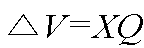
여기서 △V 는 전압변동, X는 인출 지점부터 연계 지점까지의 리액턴스, Q는 보상되는 무효전력 값을 의미한다.
본 발명에 있어서, 상기 제어부는, 무효전력 공급으로 변경된 전압을 기준으로 Q(V)curve의 동작 기준 전압을 설정하며, 이에 따라 상기 Q(V)curve를 이용해 기준에서 벗어난 위반 전압 만큼만 보상하되, 상기 Q(V)curve는 아래의 수학식 7을 이용해 설정하는 것을 특징으로 한다.
(수학식 7)


여기서 X는 리액턴스, Q는 최대 무효전력 공급용량, △V는 위반 전압을 의미한다.
본 발명의 일 측면에 따르면, 본 발명은 전압조정장치별 설정 값 설정을 통해 전압조정장치간 협조 제어를 수행할 수 있도록 하기 위하여, 실제 저압계통의 전압변동을 분석하여 구간별 고압 운영범위를 도출하고, 상기 구간별 고압 운영범위를 기준으로 전압조정장치의 설정 값을 도출할 수 있도록 한다.
도 1은 일반적인 도심지의 저압계통 범위와 농어촌 지역의 저압계통 범위를 비교하기 위하여 보인 예시도.
도 2는 본 실시예에 따른 고압 운영범위 도출 과정을 설명하기 위한 저압계통 구성을 보인 예시도.
도 3은 상기 도 2에 있어서, 구간 및 시간별 고압과 저압 전압 취득 현황을 예시적으로 보인 테이블.
도 4는 상기 도 3에 있어서, 구간 및 시간별 고압과 저압 전압을 동일기준으로 환산한 현황을 예시적으로 보인 테이블.
도 5는 상기 도 4에 있어서, 상한 및 하한 최소 여유범위를 도출한 현황을 예시적으로 보인 테이블.
도 6은 본 발명의 일 실시예에 따라 구간별로 다른 고압 운영범위를 사용하는 상황을 보인 예시도.
도 7은 본 실시예에서 대역폭을 고려한 전압프로파일의 일 예를 보인 예시도.
도 8은 본 실시예에서 목적함수를 통한 최적 값을 도출하는 상황을 예시적으로 보인 테이블.
도 9는 본 발명의 일 실시예에 따라 전압 프로파일과 고압 운영범위와의 여유를 분석한 그래프를 보인 예시도.
도 10은 본 발명의 일 실시예에 따라 구간별 최대 위반 지점 전압 보상 크기를 도출하는 방법을 설명하기 위하여 보인 예시도.
도 11은 본 발명의 일 실시예에 따른 무효전력 공급을 통한 전압 보상 방법을 설명하기 위하여 보인 예시도.
도 12는 본 발명의 일 실시예에 관련된 Q(V)곡선(Q(V)curve)을 설정 방식을 설명하기 위한 그래프를 보인 예시도.
도 13은 본 발명의 다른 실시예에 따른 DVM(Digital Voltmeter) 설정 방식과 이 설정을 적용하기 위한 그래프를 보인 예시도.
이하, 첨부된 도면을 참조하여 본 발명에 따른 전력데이터 계측기반 다수 전압조정장치의 협조 제어를 위한 설정 값 도출 방법의 일 실시예를 설명한다.
이 과정에서 도면에 도시된 선들의 두께나 구성요소의 크기 등은 설명의 명료성과 편의상 과장되게 도시되어 있을 수 있다. 또한, 후술되는 용어들은 본 발명에서의 기능을 고려하여 정의된 용어들로서 이는 사용자, 운용자의 의도 또는 관례에 따라 달라질 수 있다. 그러므로 이러한 용어들에 대한 정의는 본 명세서 전반에 걸친 내용을 토대로 내려져야 할 것이다.
이하 본 실시예의 도면에는 구체적으로 도시하지 않았으나, 본 실시예에 따른 전력데이터 계측기반 다수 전압조정장치의 협조 제어를 위한 설정 값 도출 방법을 수행하는 장치는, 씨피유(CPU, 미도시)(또는 제어부)를 포함하는 컴퓨터(미도시)나 서버(미도시)로 구현될 수 있다.
따라서 이하 설명의 편의를 위해서 구체적으로 기재하지 않더라도, 본 실시예에 따른 전력데이터 계측기반 다수 전압조정장치의 협조 제어를 위한 설정 값 도출 방법을 실행하는 주체는 제어부(미도시)로 이해되어야 한다.
이하 본 발명의 일 실시예를 위해 필요한 조건과 원리에 대해서 설명한다.
상술한 종래의 문제점을 해소하기 위해서는 아래와 같은 조건들이 필요하다.
첫 번째로 종래의 저압계통 사용자에게 허용범위 내에서 적정한 전압 공급을 위해서는 고압계통 전압이 부하변동 상황에 능동적으로 대응하여야 한다.
두 번째로 종래에는 구간별 저압계통 전압변동이 상이하기 때문에 별도의 구간별 고압 운영범위가 있어야 한다.
이때 상기 구간별 고압 운영범위를 도출하기 위해서는, 고압, 및 저압의 전압이력을 분석함으로써, 이로부터 적정한 고압 운영범위를 도출할 수 있다. 이때 상기 도출된 범위(즉, 고압 운영범위)를 기준으로 고압 전압을 유지하기 위해서는 전압조정장치의 적합한 제어가 필요하다.
그런데 전력 계통을 실시간 계측 및 제어하기 위해서는 시스템 및 통신에 많은 투자가 필요하기 때문에 현재 대부분의 전압조정장치는 중앙제어 없이 기 입력된 설정을 기반으로 운전된다. 하지만 상기 설정을 기반으로 한 전압조정장치의 운전은 해당 전압조정장치가 설치된 지점 이외의 다른 지점의 정보는 활용할 수 없기 때문에 다른 지점의 전압 현황 및 타 전압조정장치의 정보 없이 적합한 동작을 해야 한다.
따라서 이를 위해서는 계통별 부하, 발전 및 전압조정장치의 특성을 고려해 전압조정장치의 설정 값을 도출하여 설정해 주어야 한다.
본 실시예에서 다수의 전압조정장치 협조 제어를 위해서는 각 전압조정장치의 운영 기준이 되는 고압 운영범위가 필요하다.
참고로 전력계통은 전력전송을 위한 고압계통과 사용자에게 전력공급을 위한 저압계통이 있으며, 상기 저압계통은 고압계통에 비해 낮은 전압과 큰 전류로 인해 전압강하 및 변동이 크다. 즉, 상기 저압계통은 부하변동에 따라 전압변동 범위가 커서 모든 경우에 동일한 값(즉, 고압 운영범위)으로 대체하기가 어렵다.
도 1은 일반적인 도심지의 저압계통 범위와 농어촌 지역의 저압계통 범위를 비교하기 위하여 보인 예시도로서, 도 1의 (a)는 도심지의 저압계통 범위를 보인 예시도이고, 도 1의 (b)는 농어촌 지역의 저압계통 범위를 보인 예시도이다.
예컨대 도 1을 참조하면, 저압계통 범위는 도심지가 농어촌 지역에 비해서 상대적으로 짧음을 알 수 있다. 이는 같은 부하 조건일 때 전압강하가 도심지에서 더 작게 발생한다는 것을 의미한다. 이로부터 도심지의 고압 운영범위 하한은 농어촌보다 더 낮아도 된다는 것을 의미한다. 이에 따라 모든 구간에 동일한 고압 운영범위를 적용하는 것은 합리적이지 않음을 알 수 있으며, 따라서 합리적인 고압 운영범위를 도출하기 위해서는 실제 저압계통의 전압변동 분석이 필요함을 의미한다.
이때 상기 고압 운영범위를 도출하는 과정은, 제1 과정(각 구간 및 시간 별 고압과 저압 전압을 취득한다), 제2 과정(모든 시간의 고압 전압을 동일기준(예 : 1.0 pu)으로 환산하고 저압 전압에도 동일하게 적용한다), 제3 과정(저압 기준 상/하한 여유 계산 및 상/하한 최소 여유범위를 도출한다), 및 제4 과정(구간별 고압 운영범위를 도출한다)을 통해 고압 운영범위가 도출된다.
이하 상기 고압 운영범위를 도출하는 과정에 대해서 보다 구체적으로 설명한다. 도 2는 본 실시예에 따른 고압 운영범위 도출 과정을 설명하기 위한 저압계통 구성을 보인 예시도이고, 도 3은 상기 도 2에 있어서, 구간 및 시간별 고압과 저압 전압 취득 현황을 예시적으로 보인 테이블이다.
본 실시예에서는 설명의 편의상, 전압은 pu 단위, 구간은 제1 구간(TR1), 제2 구간(TR2), 그리고 시간은 1, 2, 3(시)를 적용하며, AMI(Advanced Metering Infrastructure)1, AMI2는 제1 구간(TR1 구간)에 소속되고, AMI3, AMI4는 제2 구간(TR2 구간)에 소속되는 것으로 가정한다.
이때 상기 도 3의 테이블은, 상기 고압 운영범위를 도출하기 위한 제1 과정(각 구간 및 시간 별 고압과 저압 전압을 취득하는 과정)을 통해 취득한 정보이다.
도 4는 상기 도 3에 있어서, 구간 및 시간별 고압과 저압 전압을 동일기준(예 : 1.0 pu)으로 환산(변환)한 현황을 예시적으로 보인 테이블이다.
즉, 도 4의 테이블은, 상기 고압 운영범위를 도출하기 위한 제2 과정(모든 시간의 고압 전압을 동일기준(예 : 1.0 pu)으로 환산하고 저압 전압에도 동일하게 적용한다)을 통해 취득한 정보이다.
도 4를 참조하면, 제1 구간(TR1 구간)의 1시 전압은 기존 1.02에서 1로 0.02 pu 감소되었으며, 상기 제1 구간(TR1 구간)에 소속된 AMI1과 AMI2도 동일하게 0.02 pu 감소되어 각기 1.02 pu와 0.99 pu로 변환되었다.
도 5는 상기 도 4에 있어서, 상한 및 하한 최소 여유범위를 도출한 현황을 예시적으로 보인 테이블이다.
즉, 도 5의 테이블은, 상기 고압 운영범위를 도출하기 위한 제3 과정(저압 기준 상/하한 여유 계산 및 상/하한 최소 여유범위를 도출한다)을 통해 취득한 정보이다.
이때 도 5의 테이블에서 상한은 1.06 pu, 하한은 0.94 pu를 기준으로 설정하였을 때, 상기 제1 구간(TR1 구간)에서 상한 여유가 가장 작은 것은 AMI1의 2시로서, 상한 여유는 0.02 pu(즉, 1.06-1.04=0.02)가 된다. 그리고 상기 제1 구간(TR1 구간)에서 하한 여유가 가장 작은 것은 AMI2의 3시로서, 하한 여유는 0.04 pu(즉, 0.98-0.94=0.04)가 된다.
또한 상기 제2 구간(TR2 구간)에서 상한 여유가 가장 작은 것은 AMI3의 2시로서, 상한 여유는 0.02 pu(즉, 1.06-1.04=0.02)가 된다. 그리고 상기 제2 구간(TR2 구간)에서 하한 여유가 가장 작은 것은 AMI4의 3시로서, 하한 여유는 0.01 pu(즉, 0.95-0.94=0.01)가 된다.
이에 따라 상기 도 5를 바탕으로 상기 제1 구간(TR1 구간)의 고압 운영범위를 도출하기 위하여 제4 과정(구간별 고압 운영범위를 도출한다)을 수행하면, 상기 제1 구간(TR1 구간)의 1~3시까지의 고압 운영범위는, 상한 1+0.02=1.02 pu, 하한 1-0.04=0.96 pu 임을 알 수 있다. 이와 마찬가지 방식으로 상기 제2 구간(TR2 구간)의 고압 운영범위를 도출하기 위하여 제4 과정을 수행하면, 상기 제2 구간(TR2 구간)의 1~3시까지의 고압 운영범위는, 상한 1+0.02=1.02 pu, 하한 1-0.01=0.99 pu 임을 알 수 있다.
이는 상기 제4 과정을 통해 도출된 고압 운영범위가 유지되면 상기 설정한 저압계통 전압 기준(0.94 ~ 1.06 pu)이 유지됨을 의미한다. 이는 저압계통에서 발생하는 최악의 경우를 고려하여 고압 운영범위를 도출하였기 때문이다.
다만 상기 실시예에서는 설명의 편의상 1시 ~ 3시를 한정하여 고압 운영범위를 도출하는 방법을 설명한 것이지만, 만약 시간에 따라 저압계통의 전압변동 차이가 클 경우(예 : 낮은 태양광 발전으로 전압이 상승하여 상한 여유가 좁고, 반면에 밤은 중부하로 인한 큰 전압강하로 하한 여유가 좁은 경우) 복수의 고압 운영범위를 도출하여 사용할 수 있다. 이와 같이 시간 및 계절별로 고압 운영범위가 다를 경우 복수의 고압 운영범위를 도출하여 사용할 수 있다.
도 6은 본 발명의 일 실시예에 따라 구간별로 다른 고압 운영범위를 사용하는 상황을 보인 예시도로서, 도 6의 (a)는 고압 계통도를 보인 예시도이고, 도 6의 (b)는 상기 고압 계통도에서 각 구간(예 : A1, A2, A3, ~ , A10)(또는 지점)별 고압 운영 범위를 그래프 형태로 보인 예시도이다.
상기와 같이 고압 운영범위를 도출하는 것은 전압조정장치의 운영 시 적정전압을 공급하기 위한 기준으로 사용하기 위한 것이다. 즉, 적정 전압(전압문제가 발생하지 않는 범위의 전압)을 공급하기 위한 전압조정장치의 설정을 결정하기 위한 기준으로 사용하기 위한 것이다.
참고로 상기 전압조정장치의 종류에는 OLTC(On Load Tap Changer), SVR(Static Voltage Regulator), ESS(Energey Storage System), 및 분산전원 등이 있으며, 이 중 상기 OLTC, 및 SVR은 변압기 권선 비를 바꾸어 전압을 변동시키는 방식으로 동작하며, 상기 ESS, 및 분산전원은 무효전력(예 : 진상,지상 무효전력)을 발생시켜 전압을 변동시키는 방식으로 동작한다.
이하 본 발명의 일 실시예에 따른 설정 기반으로 동작하는 전압조정장치의 설정을 도출하는 단계에 대해서 설명한다.
이때 상기 전압조정장치의 설정을 도출하는 단계는, 제1 단계(대역폭, 부하, 발전량 이력을 반영한 전압 프로파일을 생성하는 단계), 제2 단계(표준전압 준수, 전압위반 최소가 되는 설정 값을 선정하는 단계), 제3 단계(전압 위반 해소를 위한 최대 위반 지점의 전압 보상 크기를 계산하는 단계), 및 제4 단계(ESS, 및 분산전원의 설정 값을 계산하는 단계)를 포함한다.
이하 상기 전압조정장치의 설정을 위한 설정 값을 도출하는 과정에 대해서 보다 구체적으로 설명한다.
상기 제1 단계(대역폭, 부하, 발전량 이력을 반영한 전압 프로파일을 생성하는 단계)를 수행하기 위해서, 먼저, OLTC(On Load Tap Changer), SVR(Static Voltage Regulator)의 LDC(Line Drop Compensator) 운전의 개념에 대해서 설명한다.
상기 LDC는 특정 지점에 목표전압(Vref)을 부하변동에 관계없이 일정하기 유지하기 위해 송출전압(Vsend)을 변동시킨다.
상기 목표전압(Vref)과 송출전압(Vsend)의 관계는 아래의 수학식 1과 같다.

여기서 Vref, R(저항), 및 X(리액턴스)는 고정된 입력이므로, 부하변동 시 일정한 목표전압(Vref)을 유지하기 위해서는 송출전압(Vsend)을 변동한다. 즉, 상기 목표전압(Vref)을 유지하기 위해서 변동시켜야 할 송출전압(Vsend)을 계산한다.
이에 따라 상기 OLTC에서는 송출전압을 측정하여, 상기 계산된 송출전압(Vsend)과 같게 유지하기 위해서 탭을 변동시킨다. 이때 OLTC의 동작 빈도를 조절하기 위해서 대역폭을 조절하며, 상기 계산된 송출전압(Vsend)와 현재 송출전압이 대역폭 이상일 경우 탭 조정을 통해 송출전압을 조정한다.
가령, 상기 OLTC는 대역폭이 1%일 경우 계산된 송출전압(Vsend)과 현재 송출전압의 차이가 1% 이상일 경우만 동작한다.
이때 본 실시예에 따른 장치를 통해 결정해야 하는 설정은, 목표전압(Vref), 임피던스(R, X), 및 대역폭(Dead Band) 등의 설정 값이다.
이때 상기 목표전압(Vref), 임피던스(R, X), 및 대역폭(Dead Band) 값을 이용해 현실적으로 조합 가능한 생성은, 예컨대 상기 목표전압(Vref), 임피던스(R, X), 및 대역폭(Dead Band) 값이 각각 5, 5, 5, 3 개일 경우 총 375개의 설정이 조합 가능하다. 이는 t개의 부하 케이스에 대하여 각각 375개의 설정을 적용한 전압 프로파일을 생성할 수 있음을 의미하며, 가령 t=4 일 경우 1,500개의 전압 프로파일이 생성될 수 있음을 의미한다(도 7 참조).
다음 상기 제2 단계(표준전압 준수, 전압위반 최소가 되는 설정 값을 선정하는 단계)를 수행하는 방법에 대해서 설명한다.
상기 제1 단계에서 생성한 1,500가지 전압 프로파일의 목적함수(수학식 2)를 계산하고 각 설정별(375개)로 그 값을 합산한다.

이때 상기 목적함수는 계통운영 목적에 따라 달라질 수 있으며, 상기 수학식 2의 목적함수에서 고려하는 점은 아래와 같다.
1. 모든 시간(t)과 지점(i)에서 표준전압과의 차 :

2. 대역폭을 고려한 전압 위반 :

이때 전압위반의 중요성을 줄일 경우에는 가중치(ωmax, ωmax)를 1,000 보다 작게 한다.
여기서 Vi,t 는 시간(t)에 모선(i)의 구간 전압(예 : 도 5, (a)의 A1 ~ A10)이고, Vi,t DB max 는 DB 상한을 고려한 시간(t)에 모선(i)의 전압(예 : 도 7의 Vi,t DB max 참조)이며, Vi,t DB min 은 DB 하한을 고려한 시간(t)에 모선(i)의 전압(예 : 도 7의 Vi,t DB min)이고,  는 시간(t)에 따른 모선(i)의 고압 운영범위 상한(예 : TR1 구간 1.02pu),
  는 시간(t)에 따른 모선(i)의 고압 운영범위 하한(예 : TR1 구간 0.96pu) 값을 의미한다.
도 7은 본 실시예에서 대역폭을 고려한 전압프로파일의 일 예를 보인 예시도이다. 도 7을 참조하면, 대역폭(1%) 적용 시 송출전압 기준이 1.0 pu이면 가능한 최고, 및 최저 송출전압은 각기 1.02, 및 0.98 pu 임을 알 수 있다. 또한 상기 송출전압이 1.02 pu(Vi,t DB max)일 때 상한과의 전압 여유도가 가장 작고, 상기 송출전압이 0.98 pu(Vi,t DB min)일 때 하한과의 전압 여유도가 가장 작음을 알 수 있다.
도 8은 본 실시예에서 목적함수를 통한 최적 값을 도출하는 상황을 예시적으로 보인 테이블이다.
도 8을 참조하면, 설정 375개를 4개의 시간에 대해 각각 목적함수를 구하고 그 합이 최소인 조합을 선정하면, 2번째 설정(조합)이 4개의 시간동안의 목적함수 합이 최소로 적은 최적 값임을 알 수 있다.
다음 상기 제3 단계(전압 위반 해소를 위한 최대 위반 지점의 전압 보상 크기를 계산하는 단계)를 수행하는 방법에 대해서 설명한다.
먼저 기 설정된 기준으로 모든 시간동안 전압 프로파일과 고압 운영범위와의 여유를 계산한다. 이때 전압위반 가능성을 판단하기 위한 목적으로, 도 9와 같이 대역폭을 고려하여 적용한다. 그 중 고압 운영범위와 각 구간의 상한, 하한 전압 여유가 가장 작은 값을 각각 선정한다.
도 9는 본 발명의 일 실시예에 따라 전압 프로파일과 고압 운영범위와의 여유를 분석한 그래프를 보인 예시도이고, 도 10은 본 발명의 일 실시예에 따라 구간별 최대 위반 지점 전압 보상 크기를 도출하는 방법을 설명하기 위하여 보인 예시도이다.
도 9 및 도 10을 참조하면, 상한은 7번 구간, 하한은 9번 구간이 고압 운영범위에 대하여 전압 여유가 가장 작음을 알 수 있으며, 상한 및 하한 모두 위반이 발생했고, 이 전압 위반 해소를 위해 전압 제어가 필요함을 알 수 있다. 즉, 상한의 경우 0.048 pu를 하강, 하한의 경우 0.0154 pu를 상승시켜야 하는 것이다.
다음 제4 단계(ESS, 및 분산전원의 설정 값을 계산하는 단계)를 수행하는 방법에 대해서 설명한다.
먼저 무효전력에 의한 전압 보상방법은 아래의 수학식 3을 이용할 수 있다.

여기서 △V 는 전압변동, X는 인출 지점(또는 구간)부터 연계 지점(또는 구간)까지의 리액턴스, Q는 보상되는 무효전력 값을 의미한다. 이때 상기 제3 단계를 통해서 어느 지점(X)에서 필요한 전압 보상 크기(△V)를 알 수 있으며, 여기서 전압보상을 위한 무효전력은 수학식 4를 이용해 계산할 수 있다.

예컨대 무효전력 분배 방식을 설명하면, 도 11의 지점 2에서 전압이 고압 상한을 2% 초과한다고 가정할 때, Q2만 연계하고 X2=2인 경우, Q2=2/X2, Q2가 1의 지상 전력을 공급 시, 2번 지점의 전압은 2% 강하한다.
도 11은 본 발명의 일 실시예에 따른 무효전력 공급을 통한 전압 보상 방법을 설명하기 위하여 보인 예시도로서, 다수의 무효전력 공급원(예 : ESS, 분산전원)이 있을 경우 분배 방법은, 가령 도 11의 Q1, Q2, Q3 의 최대 무효전력 가능 용량의 비를 1, 3, 2라고 가정하고, 각각의 연계 지점까지의 리액턴스는 X1, X2, X3 (=1, 2, 3)으로 가정하며, 전압 위반(△V)은 2번 지점에서 +2% 발생한다고 가정할 때, Q 공급원 중 가장 큰 2번을 기준으로 용량 비로 나타내면 아래의 수학식 5가 되고, 상기 수학식 3을 이용해 표현하면 아래의 수학식 6이 된다.


참고로 상기 수학식 6에서 Q3의 리액턴스로 X3 가 아닌 X2를 쓰는 이유는 전압 변동이 기준점이 2번이기 때문이다.
한편 상기 수학식 5를 수학식 6에 대입하면, △V=X1*1/3*Q2+X2*Q2+X2*2/3*Q2 가 되고, Q2=△V/(1/3*X1+X2+2/3*X2)=2/(1/3+2+4/3)=6/11 가 된다.
이로부터 Q1에서 공급해야 하는 지상 무효전력은 (1/3)*(6/11)=2/11 이 되고, Q2에서 공급해야 하는 지상 무효전력은 6/11 이 되며, Q3에서 공급해야 하는 지상 무효전력은 (2/3)*(6/11)=4/11 가 된다. 여기서 전압 보상을 위해 계산된 분배량을 적용하여 조류계산을 하면 각 지점의 전압이 구해진다.
도 12는 본 발명의 일 실시예에 관련된 Q(V)곡선(Q(V)curve)을 설정 방식을 설명하기 위한 그래프를 보인 예시도로서, 먼저 Q(V)곡선(Q(V)curve)을 설정하기 위해서는 무효전력 공급으로 변경된 전압을 기준으로 Q(V)curve의 동작 기준 전압을 설정한다. 이때 무효전력 보상장치의 민감도는 계통 특성에 따라 다를 수 있다.
본 실시예에 따른 Q(V)curve는 기준에서 벗어난 만큼만 보상하는 방식으로서, 리액턴스는 X, 최대 무효전력 공급용량은 Q 인 Q(V)curve 설정은 아래의 수학식 7을 이용할 수 있다.


따라서 상기 수학식 7에서 Q가 1, X=5 이면 △V=5 임을 알 수 있다.
상기와 같이 본 실시예에서는 저압계통의 고객의 규정전압 준수를 위한 고압 운영범위를 도출하는 방법, 다수의 전압 조정장치의 협조 제어를 고려하여 운전 설정을 도출하는 방법, 다수의 무효전력 공급원의 무효전력 분배 계산 방법, 및 적정 전압 보상을 위한 Q(V)curve 설정을 계산하는 방법에 대해서 설명하였다.
이상으로 상술한 방법은 OLTC의 LDC 운전과 무효전력 보상장치의 Q(V)curve를 기준으로 설명한 것이나, 다른 실시예로서 OLTC의 DVM(Digital Voltmeter) 운전의 경우에는 다음과 같은 방식으로 설정 값을 도출할 수 있다(도 13 참조).
우선 최대 무효전력을 반영한 전압 프로파일 중 고압 운영범위와 여유도가 가장 작은 경우를 선정한다.
도 13은 본 발명의 다른 실시예에 따른 DVM(Digital Voltmeter) 설정 방식과 이 설정을 적용하기 위한 그래프를 보인 예시도로서, 도 13의 (a)는 DVM 설정 방식을 설명하기 위한 그래프이고, 도 13의 (b)는 DVM 설정을 적용한 그래프를 보인 예시도이다. 도 13은 송출전압을 1.0 pu로 변환하고, 고압 운영범위 여유가 가장 작은 상황을 가정한다.
상기 DVM 운전은 송출전압이 설정한 상한 및 하한을 넘어가면 즉시 전압을 제어한다. 즉, DVM 운전 방식은 LDC 운전 방식의 대역폭이 0%, R, X가 0인 경우와 동일하다고 할 수 있다.
따라서 대역폭을 고려한 송출전압을 고려할 필요가 없이 1.0 pu로 가정할 수 있으며, 2번, 및 4번 그래프는 각각 지상, 진상 무효전력을 최대로 공급받은 상태를 나타내고, 1번 화살표는 고압 운영범위 상한과의 전압 여유(V_high_margin) 정도를 나타내며, 3번 화살표는 고압 운영범위 하한과의 전압 여유(V_low_margin) 정도를 나타낸다. 즉, DVM 설정인 송출전압 상한을 1+V_high_margin pu, 하한을 1-V_low_margin pu 로 설정할 수 있다.
상술한 바와 같이 전압조정장치의 상호 협조 목적에 맞는 설정을 할 수 있으며, 만약 OLTC 동작횟수의 감소가 필요한 경우 무효전력 공급량을 증가시키며, 반대로 무효전력 공급량의 감소가 필요한 경우 OLTC DVM 대역폭을 감소시킨다.
일반적으로 배전계통의 전압관리 목적은, 저압계통 사용자(즉, 수용가)에게 적정 전압을 공급하는 것이며, 상술한 고압 운영범위 기술을 적용하면 준수해야 할 고압의 운영범위 도출이 가능하며, 이는 배전계통 운영시스템의 실시간 다수의 저압 수용가를 모니터링 할 필요가 없도록 한다. 이는 대규모 통신, 정보처리 시스템 등 인프라 투자의 감소가 가능하게 하는 효과가 있다.
또한 전압조정장치의 운영 최적화로 저압 수용가에게 적정 전압 공급이 가능하게 하고, 대규모 운영시스템, 및 통신 기반 없이도 전압조정장치의 협조 제어가 가능하게 하여 수용가에 적정 전압 공급을 할 수 있도록 하는 효과가 있다.
이상으로 본 발명은 도면에 도시된 실시예를 참고로 하여 설명되었으나, 이는 예시적인 것에 불과하며, 당해 기술이 속하는 분야에서 통상의 지식을 가진 자라면 이로부터 다양한 변형 및 균등한 타 실시예가 가능하다는 점을 이해할 것이다. 따라서 본 발명의 기술적 보호범위는 아래의 특허청구범위에 의해서 정하여져야 할 것이다.
Claims (8)
- 다수의 전압조정장치 협조 제어를 위하여, 제어부가 각 전압조정장치의 운영 기준이 되는 고압 운영범위를 도출하되,각 구간 및 시간 별 고압과 저압 전압을 취득하는 제1 과정;모든 시간의 고압 전압을 지정된 동일기준으로 환산하고 저압 전압에도 동일하게 적용하는 제2 과정;저압 기준 상한 및 하한 여유 계산, 및 상한 및 하한 최소 여유범위를 도출하는 제3 과정; 및상기 제1 내지 제3 과정에 기초하여 구간별 고압 운영범위를 도출 제4 과정을 통해 고압 운영범위를 도출하는 것을 특징으로 하는 전력데이터 계측기반 다수 전압조정장치의 협조 제어를 위한 전압조정장치의 설정 값 도출 방법.
- 제 1항에 있어서,시간에 따라 저압계통의 전압변동 차이가 기준 이상 클 경우, 또는 시간 및 계절별로 고압 운영범위가 다를 경우, 복수의 고압 운영범위를 도출하여 사용하는 것을 특징으로 하는 전력데이터 계측기반 다수 전압조정장치의 협조 제어를 위한 전압조정장치의 설정 값 도출 방법.
- 제 1항에 있어서, 상기 제어부는,전압조정장치의 운영 시 전압문제가 발생하지 않는 범위의 전압인 적정전압을 공급하기 위하여 전압조정장치의 설정을 결정하기 위한 기준으로 사용하기 위하여 상기 고압 운영범위를 산출하는 것을 특징으로 하는 전력데이터 계측기반 다수 전압조정장치의 협조 제어를 위한 전압조정장치의 설정 값 도출 방법.
- 제 3항에 있어서, 상기 제어부는,대역폭, 부하, 및 발전량 이력을 반영한 전압 프로파일을 생성하는 제1 단계;표준전압 준수, 및 전압위반 최소가 되는 설정 값을 선정하는 제2 단계;전압 위반 해소를 위한 최대 위반 지점의 전압 보상 크기를 계산하는 제3 단계; 및ESS(Energy Storage System) 및 분산전원의 설정 값을 계산하는 제4 단계;를 포함하여, 상기 전압조정장치의 설정을 위한 설정 값을 도출하는 것을 특징으로 하는 전력데이터 계측기반 다수 전압조정장치의 협조 제어를 위한 전압조정장치의 설정 값 도출 방법.
- 제 4항에 있어서, 상기 전압조정장치는,OLTC(On Load Tap Changer), SVR(Static Voltage Regulator), ESS(Energey Storage System), 및 분산전원을 포함하며,상기 OLTC, 및 SVR은 변압기 권선 비를 바꾸어 전압을 변동시키는 방식으로 동작하며, 상기 ESS, 및 분산전원은 무효전력을 발생시켜 전압을 변동시키는 방식으로 동작하는 것을 특징으로 하는 전력데이터 계측기반 다수 전압조정장치의 협조 제어를 위한 전압조정장치의 설정 값 도출 방법.
- 제 4항에 있어서, 상기 제2 단계를 수행하기 위하여,상기 제어부는,상기 제1 단계를 통해 생성한 개수의 전압 프로파일의 목적함수를 아래의 수학식 2를 통해 계산하여, 각 설정별로 시간별 값을 합산하고, 그 합이 최소인 설정을 최적 값으로 선정하는 것을 특징으로 하는 전력데이터 계측기반 다수 전압조정장치의 협조 제어를 위한 전압조정장치의 설정 값 도출 방법.(수학식 2)
 여기서 Vi,t 는 시간(t)에 모선(i)의 구간 전압이고, Vi,t DB max 는 DB 상한을 고려한 시간(t)에 모선(i)의 전압이며, Vi,t DB min 은 DB 하한을 고려한 시간(t)에 모선(i)의 전압이고,는 시간(t)에 따른 모선(i)의 고압 운영범위 상한 값,
 는 시간(t)에 따른 모선(i)의 고압 운영범위 하한 값을 의미한다.
- 제 4항에 있어서, 상기 제4 단계를 수행하기 위하여,상기 제어부는,아래의 수학식 3을 이용하여 무효전력에 의한 전압 보상을 위한 설정 값을 산출하는 것을 특징으로 하는 전력데이터 계측기반 다수 전압조정장치의 협조 제어를 위한 전압조정장치의 설정 값 도출 방법.(수학식 3)
 여기서 △V 는 전압변동, X는 인출 지점부터 연계 지점까지의 리액턴스, Q는 보상되는 무효전력 값을 의미한다.
 - 제 7항에 있어서, 상기 제어부는,무효전력 공급으로 변경된 전압을 기준으로 Q(V)curve의 동작 기준 전압을 설정하며, 이에 따라 상기 Q(V)curve를 이용해 기준에서 벗어난 위반 전압 만큼만 보상하되,상기 Q(V)curve는 아래의 수학식 7을 이용해 설정하는 것을 특징으로 하는 전력데이터 계측기반 다수 전압조정장치의 협조 제어를 위한 전압조정장치의 설정 값 도출 방법.(수학식 7)

 여기서 X는 리액턴스, Q는 최대 무효전력 공급용량, △V는 위반 전압을 의미한다.
Applications Claiming Priority (2)
| Application Number | Priority Date | Filing Date | Title |
|---|---|---|---|
| KR1020180111977A KR102068454B1 (ko) | 2018-09-19 | 2018-09-19 | 전력데이터 계측기반 다수 전압조정장치의 협조 제어를 위한 전압조정장치의 설정 값 도출 방법 |
| KR10-2018-0111977 | 2018-09-19 |
Publications (1)
| Publication Number | Publication Date |
|---|---|
| WO2020059964A1 true WO2020059964A1 (ko) | 2020-03-26 |
Family
ID=69369826
Family Applications (1)
| Application Number | Title | Priority Date | Filing Date |
|---|---|---|---|
| PCT/KR2018/015902 Ceased WO2020059964A1 (ko) | 2018-09-19 | 2018-12-14 | 전력데이터 계측기반 다수 전압조정장치의 협조 제어를 위한 전압조정장치의 설정 값 도출 방법 |
Country Status (2)
| Country | Link |
|---|---|
| KR (1) | KR102068454B1 (ko) |
| WO (1) | WO2020059964A1 (ko) |
Families Citing this family (3)
| Publication number | Priority date | Publication date | Assignee | Title |
|---|---|---|---|---|
| KR102763102B1 (ko) * | 2020-07-22 | 2025-02-07 | 한국전력공사 | 분산전원이 도입된 배전선로의 전압 제어 장치 및 방법 |
| KR102908898B1 (ko) * | 2021-11-03 | 2026-01-07 | 한국전력공사 | 배전선로에서의 oltc와 분산전원들의 설정 방법 |
| KR102775817B1 (ko) * | 2022-11-14 | 2025-03-05 | 한국전력공사 | 전압 제어 기기 설정의 정정 시스템 및 방법 |
Citations (5)
| Publication number | Priority date | Publication date | Assignee | Title |
|---|---|---|---|---|
| JP2009171688A (ja) * | 2008-01-11 | 2009-07-30 | Chugoku Electric Power Co Inc:The | 適正電圧管理方法及び適正電圧管理システム |
| JP2016036252A (ja) * | 2011-10-31 | 2016-03-17 | 三菱電機株式会社 | 配電系統電圧制御システム、配電系統電圧制御方法、集中電圧制御装置、及びローカル電圧制御装置 |
| KR20160141591A (ko) * | 2015-06-01 | 2016-12-09 | 한양대학교 산학협력단 | 전력 제어 시스템 및 방법 |
| JP2018046656A (ja) * | 2016-09-14 | 2018-03-22 | 富士電機株式会社 | 調整装置および調整方法 |
| US20180248373A1 (en) * | 2015-09-03 | 2018-08-30 | Kabushiki Kaisha Toshiba | Voltage-fluctuation suppression device and method |
Family Cites Families (4)
| Publication number | Priority date | Publication date | Assignee | Title |
|---|---|---|---|---|
| KR101132107B1 (ko) * | 2010-09-29 | 2012-04-05 | 한국전력공사 | 분산전원이 연계된 전력계통의 전압/무효전력 제어 시스템 및 이를 위한 방법 |
| JP5618294B2 (ja) * | 2010-10-13 | 2014-11-05 | 独立行政法人産業技術総合研究所 | 高圧・低圧配電系統電圧調節システム |
| KR101480533B1 (ko) * | 2013-06-28 | 2015-01-08 | 한국전력공사 | 분산전원 전력계통 연계 운전장치 및 방법 |
| KR101806041B1 (ko) * | 2016-09-26 | 2017-12-07 | 한국전력공사 | 스케줄링 기반 배전선로 전압제어 방법 및 전압제어 시스템 |
-
2018
- 2018-09-19 KR KR1020180111977A patent/KR102068454B1/ko active Active
- 2018-12-14 WO PCT/KR2018/015902 patent/WO2020059964A1/ko not_active Ceased
Patent Citations (5)
| Publication number | Priority date | Publication date | Assignee | Title |
|---|---|---|---|---|
| JP2009171688A (ja) * | 2008-01-11 | 2009-07-30 | Chugoku Electric Power Co Inc:The | 適正電圧管理方法及び適正電圧管理システム |
| JP2016036252A (ja) * | 2011-10-31 | 2016-03-17 | 三菱電機株式会社 | 配電系統電圧制御システム、配電系統電圧制御方法、集中電圧制御装置、及びローカル電圧制御装置 |
| KR20160141591A (ko) * | 2015-06-01 | 2016-12-09 | 한양대학교 산학협력단 | 전력 제어 시스템 및 방법 |
| US20180248373A1 (en) * | 2015-09-03 | 2018-08-30 | Kabushiki Kaisha Toshiba | Voltage-fluctuation suppression device and method |
| JP2018046656A (ja) * | 2016-09-14 | 2018-03-22 | 富士電機株式会社 | 調整装置および調整方法 |
Also Published As
| Publication number | Publication date |
|---|---|
| KR102068454B1 (ko) | 2020-01-21 |
Similar Documents
| Publication | Publication Date | Title |
|---|---|---|
| WO2019225834A1 (ko) | 에너지 저장 장치와 태양광 발전을 이용한 전력 공급 제어 시스템 및 방법 | |
| WO2014208816A1 (ko) | 분산전원 전력계통 연계 운전장치 및 방법 | |
| WO2018056500A1 (ko) | 스케줄링 기반 배전선로 전압제어 방법 및 전압제어 시스템 | |
| WO2020059964A1 (ko) | 전력데이터 계측기반 다수 전압조정장치의 협조 제어를 위한 전압조정장치의 설정 값 도출 방법 | |
| WO2016105103A1 (ko) | 다중 에너지저장장치 시스템의 계통 주파수 제어 방법 및 그를 위한 시스템 | |
| JP4610762B2 (ja) | 電力伝送ネットワークの安定度を査定するための方法及び装置 | |
| WO2020013619A1 (ko) | 전력계통 신뢰도 지수를 토대로 한 변전소 자산 관리 방법 및 장치 | |
| WO2019074192A1 (ko) | 분산 전원이 연계된 배전계통의 분산 전원의 출력 제어 방법, 이를 수행하기 위한 제어 동작을 수행하는 주 제어장치 및 지역 제어 장치 | |
| WO2018199658A1 (ko) | 전력설비의 자산관리 방법 | |
| CA1180755A (en) | Method of operating a high voltage direct current transmission system | |
| WO2013047927A1 (ko) | 스마트 배전 운영시스템의 보호기기 자동정정 장치 및 방법 | |
| WO2017018584A1 (ko) | 마이크로그리드의 멀티 주파수 제어 시스템 및 방법 | |
| WO2016032130A1 (ko) | Ami 전력 사용량 기반의 배전 구간부하 산출 시스템 | |
| WO2019107806A1 (ko) | 계층형 전력 제어 시스템 | |
| WO2023075258A1 (ko) | 스마트 변압기를 이용한 배전 계통 제어 시스템 | |
| WO2022085833A1 (ko) | 태양광발전 노후 진단 시스템 | |
| WO2012043938A1 (ko) | 전력조류 제어 시스템 및 방법 | |
| CN111650418A (zh) | 一种智能低压分路传感器温度补偿方法 | |
| WO2023063464A1 (ko) | 저압 배전망에서의 에너지 저감을 위한 cvr 제어 방법 및 그 장치 | |
| WO2021210716A1 (ko) | 통합 마이크로그리드 환경에서 빅데이터에 기반한 통합 데이터 서비스를 수행하는 플랫폼 장치 | |
| WO2020130366A1 (ko) | 전력 그리드 제어 장치 및 시스템 | |
| WO2018236038A1 (ko) | 에너지 저장 시스템 | |
| CN112130088A (zh) | 一种假负载测试装置及其功率自动调节方法 | |
| WO2019235657A1 (en) | Solar energy storage system divided into daytime and night mode, and its operation method and battery replacement method thereof | |
| CN114301182B (zh) | 智能电源管理系统 |
Legal Events
| Date | Code | Title | Description |
|---|---|---|---|
| 121 | Ep: the epo has been informed by wipo that ep was designated in this application |
Ref document number: 18934291 Country of ref document: EP Kind code of ref document: A1 |
|
| NENP | Non-entry into the national phase |
Ref country code: DE |
|
| 122 | Ep: pct application non-entry in european phase |
Ref document number: 18934291 Country of ref document: EP Kind code of ref document: A1 |