WO2020056944A1 - 一种塔扇走线结构及其塔扇 - Google Patents
一种塔扇走线结构及其塔扇 Download PDFInfo
- Publication number
- WO2020056944A1 WO2020056944A1 PCT/CN2018/121136 CN2018121136W WO2020056944A1 WO 2020056944 A1 WO2020056944 A1 WO 2020056944A1 CN 2018121136 W CN2018121136 W CN 2018121136W WO 2020056944 A1 WO2020056944 A1 WO 2020056944A1
- Authority
- WO
- WIPO (PCT)
- Prior art keywords
- wiring
- support base
- positioning
- component
- motor
- Prior art date
Links
Images


Classifications
-
- H—ELECTRICITY
- H02—GENERATION; CONVERSION OR DISTRIBUTION OF ELECTRIC POWER
- H02G—INSTALLATION OF ELECTRIC CABLES OR LINES, OR OF COMBINED OPTICAL AND ELECTRIC CABLES OR LINES
- H02G3/00—Installations of electric cables or lines or protective tubing therefor in or on buildings, equivalent structures or vehicles
- H02G3/02—Details
- H02G3/04—Protective tubing or conduits, e.g. cable ladders or cable troughs
- H02G3/0406—Details thereof
Definitions
- the invention belongs to the technical field of tower fans, and particularly relates to a tower fan wiring structure and a tower fan.
- the tower fan is a three-dimensional exchange system between indoor and outdoor air according to the principle of airflow.
- the tower fan usually "swings" the wind through the cross-flow fan to form the airflow, that is, the centrifugal wind is generated by the wind pressure after the wind wheel rotates Finally, the wind is transmitted through the internal wind deflector.
- the cross-flow wind wheel is generally cylindrical, a three-dimensional air flow wall or air curtain is obtained by using a tower fan.
- the air curtain is perpendicular to the ground and blows left and right.
- Cross flow wind wheel has many wind blades, the air supply is even and soft, very close to the natural wind.
- the tower fan is used with air conditioners to form a circulation of airflow, which is suitable for families with elderly and children. Its 360-degree air supply makes the room free of dead air and makes people feel comfortable.
- the existing tower fans are gradually developing into intelligence.
- the wiring inside the smart inner-rotating tower fan is also increasing.
- Most existing smart tower fan products use wire clamps to wrap the wires. Fasten the clamp to the screw post with fasteners such as screws.
- the existing tower fans mainly have the following disadvantages: the use of clamps and screws in the wiring inside the machine, which is time-consuming and laborious to disassemble, and the production efficiency is too low; The components or the whole machine work normally; there is electromagnetic interference in the wiring, which affects the EMC anti-interference performance of the whole machine; multiple parts need to be developed for internal wiring and wiring, and further occupy a small internal space of the tower fan.
- the present invention provides a tower fan wiring structure and a tower fan.
- the tower fan wiring structure and the specific technical solution of the tower fan of the present invention are as follows:
- a tower fan wiring structure includes a support base and at least one wiring component connected to the support base, the wiring component has wiring, and at least one wiring connection component is formed on the support base.
- the wiring of at least one wiring component is respectively mounted on a support base through the corresponding wiring connection assembly.
- a positioning component for fixing a wiring component is provided on the support base, the positioning component fixedly connects the wiring component to the support base, and the wiring connection component on the support base and the The wiring of at least one wiring component is connected, and the wiring connection component can guide and limit the wiring of the wiring of the at least one wiring component.
- the at least one wiring member is a micro switch board
- the micro switch board includes a micro switch board body and a micro switch board wire
- the support seat is provided with a micro switch board positioning assembly and a first A wiring connection component
- the micro switch plate positioning component fixedly connects the micro switch plate to the support base
- the first wiring connection component is wire-connected to the micro switch plate
- the first distribution The wire connection component can guide the wires of the micro switch board and fix the position.
- the micro switch board positioning assembly includes a first receiving groove, a first screw post, a first positioning post, and a first limit buckle provided on the support base.
- the micro switch board body matches and can accommodate the micro switch board body.
- the micro switch board body is provided with a micro switch board positioning hole, and the first positioning post is embedded in the micro switch board positioning hole.
- the first limit buckle of the support base restricts the micro switch board body, and a screw is fastened on the first screw post of the support base to the micro switch board body To be fixed.
- the first wiring connection assembly includes a micro switch board wire passing slot and a first guide positioning card seat, and the micro switch board wire passes through the micro switch passing through the wire slot and communicates with the first The guiding and positioning card seat is connected, and the micro switch plate wire is led out after being guided and positioned by the first guiding and positioning card seat.
- the first wiring connection assembly further includes a second guide positioning card holder, and the micro switch board wire passes through the micro switch through the wire slot and is connected to the first guide positioning card holder,
- the first guiding and positioning card seat is connected to the second guiding and positioning card seat after being guided and positioned, and the micro switch plate wire is led out after being guided and positioned by the second guiding and positioning card seat.
- the micro switch board wire is connected to the line switch buckle, and the line switch buckle is connected to the micro switch switch wire. The positioning is performed, and the micro switch board wire is drawn out after the line clamp is buckled.
- the line-clamping buckle is an arc-shaped buckle
- the arc-shaped line-closing buckle is buckled on a support base, and the line-closing buckle forms a wire hole with a surface of the support base.
- the at least one wiring component is a motor assembly, and the motor assembly includes a motor and a motor wiring.
- the support base is provided with a motor positioning component and a second wiring connection component, and the motor positioning component fixes the motor.
- the second wiring connection component is connected to the motor wiring and can guide and limit the motor wiring.
- the motor positioning assembly includes a second receiving groove and a second positioning post provided on the support base, and the shape of the second receiving groove matches the motor and can accommodate the motor.
- the motor is provided on the motor. There is a positioning hole. After the motor is installed in the second receiving slot, the second positioning post on the support base is embedded in the positioning hole on the motor.
- the second wiring connection component includes a motor wiring via hole, a motor wiring groove, and a line catch provided on the support base, and the second wiring connection component is provided on the support base.
- the motor and the motor positioning assembly are disposed on the other side of the support base, and the motor wiring is guided from one side of the support base to the other side of the support base.
- the at least one wiring component is a grating switch board
- the grating switch board includes a grating switch board body and a grating switch board line
- the support seat is provided with a grating switch board positioning component and a third wiring connection component
- the grating switch plate positioning component fixedly connects the grating switch plate to the support base
- the third wiring connection component is connected to the grating switch plate and can guide and limit the grating switch plate line. The bit is fixed.
- the grating switch board positioning assembly includes a third receiving groove, a third positioning post, and a third screw post provided on a support base.
- the grating switch board body is provided with a screw via hole and a positioning hole.
- the shape and structure of the three receiving grooves are matched with the grating switch plate body and can accommodate the grating switch plate body.
- the third A positioning post is embedded in the positioning hole on the grating switch board body, and a screw is fastened to the third screw post on the support base through the screw via hole on the grating switch board body.
- the third wiring connection assembly includes a grating switch via, a third guide positioning bracket, and a second limit buckle, and the grating switch board line passes through the grating switch via and communicates with the third
- the guide and positioning clamp is connected, and after being guided and positioned by the third guide and positioning clamp, it is connected to the second limit clamp, and the grating switch plate line is led out after being guided and positioned by the second limit clamp.
- the third wiring connection component is disposed on one side of the support base, and the grating switch plate body and the grating switch plate positioning component are disposed on the other side of the support base, and the grating switch plate The wire is guided from one side of the support base to the other side of the support base.
- the second limit buckle is an M-shaped buckle, which includes two L-shaped sub-clips, the L-shaped sub-clip is buckled on the support base, and the L-shaped sub-clip has a barb on the top.
- the at least one wiring connection component is all disposed on the same side of the support base.
- the wiring connection assembly includes a guide positioning clamp
- the guide positioning clamp includes a limit retaining rib and a U-shaped wire trough formed in the limit retaining rib
- the limit retaining rib includes a U-shaped limit
- the position-retaining ribs and the in-line limit-retaining ribs are arranged opposite to each other, thereby defining the U-shaped crossing groove.
- a tower fan includes the tower fan wiring structure described above.
- FIGS. 1 and 2a-2c are exploded structural schematic diagrams of a tower fan wiring structure and a wiring component connected to the tower fan wiring structure of the present invention
- FIG. 3 is a schematic structural diagram of a tower fan wiring structure according to the present invention.
- FIG. 4 is a comparison view before and after assembling a tower fan wiring structure and a micro switch board line according to the present invention
- FIG. 5 is a comparison view before and after assembly of a tower fan wiring structure and a motor wiring assembly of the present invention
- FIG. 6 is a comparison view before and after assembling a tower fan wiring structure and a grating switch board line according to the present invention
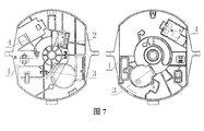
- FIG. 7 is a schematic diagram of the tower fan wiring structure and the wiring assembly wiring of all the wiring components of the present invention.
- Reference numerals are: 1, support base; 101, grating switch through hole; 102, third wire trough; 103, third limit retaining rib; 104, first screw post; 105, first positioning post; 106, The first limit buckle; 107, the micro switch through the wire groove; 108, the first limit wire rib; 109, the first wire groove; 110, the second wire groove; 111, the second limit wire rib; 112, wire trough; 113, line catch; 115, second positioning post; 114, second limit snap; 116, third positioning post; 117, third screw post; 118, motor wiring via ; 2, micro switch board body; 201, positioning hole; 3, motor; 301, positioning hole; 4, grating switch board line; 401, screw through hole; 402, positioning hole.
- the tower fan wiring structure of the present invention includes a support base and a plurality of wiring components connected to the support base.
- the wiring components may be various electrical components with wiring, such as grating switches Boards, motors, and micro switch boards, etc., a plurality of wiring connection components are provided on the support base, and a plurality of wiring components are respectively installed on the support base through the wiring connection components on the support base, thereby completing each wiring component. Independent assembly.
- the wiring component is a micro-switch board.
- the micro-switch board includes a micro-switch board body 2 and a micro-switch board wire.
- the support base 1 has a circular plate shape.
- the base 1 is provided with a micro switch plate positioning component and a first wiring connection component for connecting the micro switch plate line.
- the micro switch plate positioning component fixedly connects the micro switch plate to the support base 1 and the support base 1
- the first wiring connection component on the upper side connects and guides the micro switch board line, and performs limit fixing on the micro switch board line.
- the micro switch board positioning assembly includes a first receiving groove, a first screw post 104, a first positioning post 105, and a first limit buckle 106 provided on the support base 1.
- the shape of the receiving groove matches the micro switch board body 2.
- the micro switch board body 2 can be accommodated.
- the micro switch board body 2 is provided with a micro switch board positioning hole 201.
- the first positioning post 105 is embedded in the positioning hole 201 on the micro switch board body 2.
- the first limit buckle 106 limits the micro switch board body 2, and the screws are fastened on the first screw post 104 of the support base 1 to further fix the micro switch board body 2.
- a first wiring connection component is formed on the support base 1 and is arranged adjacent to the micro switch board positioning component.
- the first wiring connection component includes a micro switch wire trough 107, a first guide positioning card seat, and a second guide positioning.
- the card seat is a micro switch board installed on the support base 1 through a micro switch board positioning component.
- the micro switch board wire passes through the micro switch through the wire slot 107 and is connected to the first guide positioning card seat.
- the guide and positioning card seat is connected to the second guide and positioning card seat after being guided and positioned, and the micro switch plate wire is led out after being guided and positioned by the second guide and positioning card seat.
- the micro switch plate line is connected to the line clamp 113 through the second guide positioning card seat guide.
- the line clamp 113 locates the micro switch plate line, and the micro switch plate line is led out after the line clamp 113.
- the line-clamping buckle 113 is an arc-shaped buckle, and the arc-shaped line-closing buckle 113 is buckled on the support base 1, and the surface of the line-clamping buckle 113 and the support base 1 forms a micro switch plate wire passing hole.
- the first guide positioning card holder includes a first limit stop rib 108 and a first wire passing groove 109 formed in the first limit stop rib 108
- the second guide positioning card holder includes a second The limiting rib 111 and the second wire passing groove 110 formed in the second limiting rib 111
- the first limiting rib 108 includes a U-shaped limiting rib and a single-shaped limiting rib, and the U-shaped limiting rib and the single-shaped limiting rib are oppositely disposed, thereby defining a U-shaped first ⁇ ⁇ ⁇ 109 ⁇ One over the wire slot 109.
- the second limiting rib 111 includes a U-shaped limiting rib and a single-shaped limiting rib.
- the U-shaped limiting rib and the single-shaped limiting rib are oppositely disposed, thereby defining a U-shaped second crossing line. Slot 110.
- the micro switch board when the micro switch board is wired, it passes through the micro switch on the support base 1 through the wire slot 107, the first wire slot 109, the first limit rib 108, the second wire slot 110, and the second limit.
- the retaining ribs 111 and the line-clamping buckle 113 complete the routing and positioning constraints.
- the micro switch wire passing groove 107 guides and fixes the micro switch board wire.
- the first limit rib 108 and the first wire slot 109, the second limit rib 111 and the second wire slot 110 are formed separately.
- the U-shaped card holder structure guides and protects the micro switch board line, making it difficult to loosen the micro switch board line, and improving the reliability of installation and connection.
- the wiring components are motor components, such as stepper motor components.
- the motor components include the motor 3 and the motor wiring.
- the support base 1 is provided with a motor positioning component and is used to connect the motor wiring.
- the second wiring connection component of the motor, the motor positioning component fixedly connects the motor to the support base 1.
- the second wiring connection component on the support base 1 connects and guides the motor wiring, and limits and fixes the motor wiring.
- the motor positioning assembly includes a second receiving groove and a second positioning post 115 provided on the support base 1.
- the shape of the second receiving groove matches the motor 3 and can accommodate the motor 3.
- the motor 3 is provided with a positioning hole 301, and the motor 3 is mounted to After the second receiving groove, the second positioning post 115 on the support base 1 is embedded in the positioning hole 301 on the motor 3, thereby completing the positioning and installation of the motor.
- the second wiring connection assembly includes a motor wiring via 118, a motor wiring groove 112, and a line catch 113 provided on the support base 1.
- the motor wiring via 118 is close to the second receiving groove or the second positioning post 115. It is provided that the motor passing groove 112 and the collecting line buckle 113 are disposed on one side of the support base 1, and the motor 3 and the motor positioning component are disposed on the other side of the support base 1, thereby facilitating the wiring of the motor from one side of the support base 1. The side is guided to the other side of the support base 1 to meet the installation requirements.
- the motor wire passing groove 112 is a common notch groove.
- the second wiring connection component and the first wiring connection component are disposed on the same side of the support base 1.
- the motor wiring when wiring the motor wiring, the motor wiring first extends from one side of the support base 1 through the motor wiring vias 118 on the support base 1 to the other side of the support base 1, and then passes through the motor through the wire slot in order. 112. After the guide and positioning of the line catch 113 is led out. Among them, the motor through the wire trough 112 and the collection line buckle 113 play a guiding and positioning protection role on the motor wiring, making it difficult for the motor wiring to loosen and improving the reliability of installation and connection.
- the wiring component is a grating switch board.
- the grating switch board includes a grating switch board body and a grating switch board wire 4.
- the support base 1 is a circular plate.
- the support base 1 is provided with a grating.
- the switch board positioning component and a third wiring connection component for connecting the grating switch plate line 4, the grating switch plate positioning component fixedly connects the grating switch plate to the support base 1, and the third wiring connection component on the support base 1 is connected. 2. Guide the grating switch plate line 4 and limit and fix the grating switch plate line 4.
- the grating switch board positioning assembly includes a third receiving groove, a third positioning post 116, and a third screw post 117 provided on the support base 1.
- the grating switch board body is provided with a screw via 401 and a positioning hole 402, and a third receiving groove.
- the shape and structure of the grating switch plate body can be matched with the grating switch plate body.
- the third positioning post 116 on the support base 1 is embedded in the positioning hole 402 on the grating switch plate body.
- the screw is fastened to the third screw post 117 on the support base 1 through a screw via 401 on the grating switch plate body.
- the third wiring connection component is formed on the support base 1 and is disposed adjacent to the grating switch board positioning component.
- the third wiring connection component includes a grating switch via hole 101, a third guide positioning card seat, and a second limit catch 114.
- the grating switch board is installed on the support base 1 by the grating switch board positioning assembly.
- the grating switch board line 4 passes through the grating switch via hole 101 and is connected to the third guide positioning card holder.
- the third guide positioning card holder is used for positioning. It is then connected to the second limit buckle 114, and the grating switch board line 4 is guided and positioned by the second limit buckle 114 and then led out.
- the third guide positioning bracket includes a third limiting rib 103 and a third wire passing groove 102 formed in the third limiting rib 103.
- the third limiting rib 103 includes a U-shaped limiting rib and a single-shaped limiting rib.
- the U-shaped limiting rib and the single-shaped limiting rib are oppositely disposed, thereby defining a U-shaped first limiting rib. ⁇ ⁇ ⁇ 102 ⁇ Three over the wire slot 102.
- the third wiring connection component is disposed on one side of the support base 1, and the grating switch plate body and the grating switch plate positioning component are disposed on the other side of the support base 1, thereby facilitating the grating switch plate line 4 from one side of the support base 1. Guide to the other side of the support base 1 to meet the installation requirements.
- the third wiring connection component and the first wiring connection component are disposed on the same side of the support base 1.
- the grating switch plate line 4 when the grating switch plate line 4 is wired, the grating switch plate line 4 first passes through the grating switch via hole 101 on one side of the support base 1 and extends to the other side of the support base 1, and then sequentially passes through the third passing line.
- the third limiting rib 103 and the third wire passing groove 102 form a U-shaped card-like structure, which guides and protects the grating switch plate wire 4 so that the grating switch plate wire 4 is not easy to loose and the reliability is improved.
- the second limit buckle 114 is an M-shaped buckle and includes two L-shaped sub-clips.
- the L-shaped sub-clip is buckled on the support base 1.
- the top of the L-shaped sub-clip has a barb.
- micro switch board line and the motor wiring mentioned above are all led out through the hub catch 113, the micro switch board line and the motor wiring can be led out through the same hub snap 113 or separately through their respective The hub clip 113 is led out.
- the motor, the motor wiring, the micro switch board body, the micro switch board line, the grating switch board body, and the grating switch board line 4 are integrated and mounted on the same support base 1.
- the wiring in the machine can be fixed in multiple directions, so that the wirings are not staggered to each other, and the disorderly wiring of the wiring can affect the operation of the tower fan.
- the screw assembly and wiring disassembly are also reduced.
- the installation time is greatly reduced, and the production efficiency is improved.
- by fixing multiple wirings separately the interference of different wirings on each other is eliminated, and the EMC immunity of the whole machine is improved.
- the wiring of multiple wiring components is connected and fixed through a single support base 1 for an integrated fixing design.
- the internal wiring is concealed and fixed in the support base 1 without affecting the support base and the air duct components and the movement mechanism. assembly.
- the wiring connection methods of the above three wiring components can be used with each other, and the wiring of the motor uses the micro switch board line or the grating switch board line 4. Structure and method, so as to replace the wiring connection assembly (including the first wiring connection assembly, the second wiring connection assembly, and the third wiring connection assembly) according to different functions realized by the whole machine.
- the invention also discloses a tower fan.
- the tower fan includes the above-mentioned tower fan wiring structure.
- the tower fan having the above-mentioned tower fan wiring structure has better safety performance and long service life.
Abstract
一种塔扇走线结构及其塔扇,其中,塔扇走线结构包括支撑座(1)以及与支撑座(1)相连的至少一个配线部件,配线部件具有配线,支撑座(1)上形成有至少一个配线连接组件,所述至少一个配线部件的配线分别通过对应的配线连接组件安装在支撑座(1)上。上述塔扇走线结构通过将多个配线部件的配线分别利用配线连接组件固定在支撑座(1)上,多方向地实现配线固定,将配线隐藏式地固定在机身支撑座(1)内部,避免配线凌乱排布影响其他元器件或者整机运转,同时节省塔扇内部空间。
Description
本发明属于塔扇技术领域,尤其涉及一种塔扇走线结构及其塔扇。
塔扇是根据气流学原理,让室内与室外空气形成立体交换系统,塔扇通常是把风通过贯流风机“甩”出,形成气流,也即通过风轮转动后造成风压产生离心式风力最后经过内部导风壁将风力传送出去。由于贯流风轮一般为圆筒状,因此使用塔扇获得的是立体状的气流墙或风幕,该风幕垂直于地面,左右摇摆吹送。贯流风轮具有很多的风叶,送风均匀柔和,非常接近于自然风。塔扇搭配空调使用,形成气流的循环,适合有老人及小孩的家庭,其360度全方位送风,让房间无送风死角,让人感觉舒适。
目前,现有的塔扇逐渐向智能化发展,为实现功能多样化,智能内转塔扇内部的配线也越来越多,现有的大多数智能塔扇产品使用线夹裹住线材,再用螺钉等紧固件将线夹紧固于螺钉柱上。
现有的布线方式及结构需要使用较多的螺钉,而且装配拆装也费时费力。此外,对于现有的智能塔扇,由于走线不可控,容易造成走线干涉元器件,以及各个配线之间存在电磁干扰,影响整机EMC抗干扰性能,内部配线涉及的零件过多,进一步占用塔扇狭小的内部空间。因此现有的塔扇主要存在以下缺点:机内配线使用线夹、螺钉辅助,拆装费时费力,生产效率太低;机内配线交错排布,凌乱不易分清且不可控,容易干涉其他元器件或者整机正常工作;走线不规范存在电磁干扰,影响整机EMC抗干扰性能;需开发多个零件进行内部配线的布线,进一步占用塔扇狭小的内部空间。
发明内容
为解决上述现有技术中的问题,本发明提供了一种塔扇走线结构及其塔扇。
为实现上述目的,本发明的塔扇走线结构及其塔扇的具体技术方案如下:
一种塔扇走线结构,包括支撑座以及与所述支撑座相连的至少一个配线部件,所述配线部件具有配线,所述支撑座上形成有至少一个配线连接组件,所述至少一个配线部件的配线分别通过对应的所述配线连接组件安装在支撑座上。
进一步,所述支撑座上设置有用于固定配线部件的定位组件,所述定位组件将配线部件固定连接在所述支撑座上,所述支撑座上的所述配线连接组件与所述至少一个配线部件的配线相连,所述配线连接组件可对所述至少一个配线部件的配线进行走线引导和限位固定。
进一步,所述至少一个配线部件为微动开关板,所述微动开关板包括微动开关板本体和微动开关板线,所述支撑座上设置有微动开关板定位组件和第一配线连接组件,所述微动开关板定位组件将微动开关板固定连接在所述支撑座上,所述第一配线连接组件与所述微动开关板线连接,所述第一配线连接组件可对所述微动开关板线进行走线引导和限位固定。
进一步,所述微动开关板定位组件包括所述支撑座上设置的第一容纳槽、第一螺钉柱、第一定位柱、第一限位卡扣,所述第一容纳槽的形状与所述微动开关板本体匹配并可容纳所述微动开关板本体,所述微动开关板本体上设置有微动开关板定位孔,所述第一定位柱嵌入所述微动开关板定位孔中,所述支撑座的所述第一限位卡扣对所述微动开关板本体进行限位,螺钉紧固在支撑座的所述第一螺钉柱上以对所述微动开关板本体进行固定。
进一步,所述第一配线连接组件包括微动开关板线过线槽和第一导向定位卡座,所述微动开关板线穿过所述微动开关过线槽后与所述第一导向定位卡座相连,所述微动开关板线经所述第一导向定位卡座导向定位后引出。
进一步,所述第一配线连接组件还包括第二导向定位卡座,所述微动开关板线穿过所述微动开关过线槽后与所述第一导向定位卡座相连,经所述第一导向定位卡座导向定位后再与所述第二导向定位卡座相连,所述微动开关板线经所述第二导向定位卡座导向定位后引出。
进一步,所述微动开关板线经所述第一导向定位卡座或所述第二导向定位卡座导向后与集线卡扣相连,所述集线卡扣对所述微动开关板线进行定位,所述微动开关板线经所述集线卡扣后引出。
进一步,所述集线卡扣为弧形卡扣,弧形的所述集线卡扣倒扣在支撑座上,所述集线卡扣与所述支撑座的表面形成过线孔。
进一步,所述至少一个配线部件为电机组件,所述电机组件包括电机和电机配线,所述支撑座上设置有电机定位组件和第二配线连接组件,所述电机定位组件将电机固定连接在所述支撑座上,所述第二配线连接组件与所述电机配线连接并可对所述电机配线进行引导和限位固定。
进一步,所述电机定位组件包括所述支撑座上设置的第二容纳槽和第二定位柱,所述第二容纳槽的形状与所述电机匹配并可容纳所述电机,所述电机上设置有定位孔,所述电机安装到所述第二容纳槽后,支撑座上的所述第二定位柱嵌入所述电机上的所述定位孔中。
进一步,所述第二配线连接组件包括设置在所述支撑座上的电机配线过孔、电机过线槽以及集线卡扣,所述第二配线连接组件设置在所述支撑座的一侧面,所述电机和所述电机定位组件设置在所述支撑座的另一侧面,所述电机配线从所述支撑座的一侧面被引导至所述支撑座的另一侧面。
进一步,所述至少一个配线部件为光栅开关板,所述光栅开关板包括光栅开关板本体和光栅开关板线,所述支撑座上设置有光栅开关板定位组件和第三配线连接组件,所述光栅开 关板定位组件将所述光栅开关板固定连接在所述支撑座上,所述第三配线连接组件与所述光栅开关板连接并可对所述光栅开关板线进行引导和限位固定。
进一步,所述光栅开关板定位组件包括设置在支撑座上的第三容纳槽、第三定位柱以及第三螺钉柱,所述光栅开关板本体上设置有螺钉过孔和定位孔,所述第三容纳槽的形状构造与所述光栅开关板本体匹配并可容纳所述光栅开关板本体,所述光栅开关板本体安装到所述第三容纳槽后,所述支撑座上的所述第三定位柱嵌入所述光栅开关板本体上的所述定位孔中,螺钉通过所述光栅开关板本体上的所述螺钉过孔紧固至所述支撑座上的所述第三螺钉柱。
进一步,所述第三配线连接组件包括光栅开关过孔、第三导向定位卡座以及第二限位卡扣,所述光栅开关板线穿过所述光栅开关过孔后与所述第三导向定位卡座相连,经所述第三导向定位卡座导向定位后再与所述第二限位卡扣相连,所述光栅开关板线经所述第二限位卡扣导向定位后引出。
进一步,所述第三配线连接组件设置在所述支撑座的一侧面,所述光栅开关板本体和所述光栅开关板定位组件设置在所述支撑座的另一侧面,所述光栅开关板线从所述支撑座的一侧面引导至所述支撑座的另一侧面。
进一步,所述第二限位卡扣为M型卡扣,包括两个L字形的子卡扣,L字形的子卡扣倒扣在支撑座上,L字形的子卡扣顶部具有倒钩。
进一步,所述至少一个配线连接组件均设置在所述支撑座的同一侧面。
进一步,所述配线连接组件包括导向定位卡座,所述导向定位卡座包括限位挡筋和形成于限位挡筋内的U字形过线槽,所述限位挡筋包括U字形限位挡筋和一字型限位挡筋,所述U字形限位挡筋和所述一字型限位挡筋相对设置,从而限定出所述U字形过线槽。
一种塔扇,所述塔扇包括上述的塔扇走线结构。
本发明的塔扇走线结构具有以下优点:
1)将多个配线部件的配线分别利用配线连接组件固定在支撑座上,多方向地实现配线固定,将配线隐藏式的固定在机身支撑座内部,避免配线凌乱排布影响其他元器件或者整机运转,同时节省塔扇内部空间。
2)通过设计M型卡扣和U型卡槽结构,将多跟配线分开固定,配线不易松动,安全可靠性提高,同时减少装配螺钉,配线拆装时间大幅度减少,生产效率提高。
3)将多个配线部件的配线进行有序性的规范走线,避免不同配线间的电磁干扰,提高整机EMC抗干扰能力。
4)将多个配线一体化固定于一个零件上,在不影响零件本身功能的同时,集中布线,节省产品开模零件,避免多个零件与配线走线及走线涉及的多个零件组装带来的效率低下问题。
图1、图2a-2c为本发明塔扇走线结构及与塔扇走线结构相连的配线部件的分解结构示意图;
图3为本发明塔扇走线结构的结构示意图;
图4为本发明塔扇走线结构与微动开关板线装配前后对比图;
图5为本发明塔扇走线结构与电机配线装配前后对比图;
图6为本发明塔扇走线结构与光栅开关板线装配前后对比图;
图7为本发明塔扇走线结构与所有配线部件走线装配示意图。
附图标记为:1、支撑座;101、光栅开关过孔;102、第三过线槽;103、第三限位挡筋;104、第一螺钉柱;105、第一定位柱;106、第一限位卡扣;107、微动开关过线槽;108、第一限位挡筋;109、第一过线槽;110、第二过线槽;111、第二限位挡筋;112、过线槽;113、集线卡扣;115、第二定位柱;114、第二限位卡扣;116、第三定位柱;117、第三螺钉柱;118、电机配线过孔;2、微动开关板本体;201、定位孔;3、电机;301、定位孔;4、光栅开关板线;401、螺钉过孔;402、定位孔。
为了更好地了解本发明的目的、结构及功能,下面结合附图,对本发明的塔扇走线结构及其塔扇做进一步详细的描述。
如图1、图2a-2c所示,本发明塔扇走线结构包括支撑座以及与支撑座相连的多个配线部件,配线部件可以是具有配线的多种电器元件,如光栅开关板、电机以及微动开关板等,支撑座上设置有多个配线连接组件,多个配线部件分别通过支撑座上的配线连接组件安装在支撑座上,从而使各个配线部件完成独立组装。
如图2a-2c、图3-4所示,配线部件为微动开关板,微动开关板包括微动开关板本体2和微动开关板线,支撑座1呈圆形板状,支撑座1上设置有微动开关板定位组件和用于连接微动开关板线的第一配线连接组件,微动开关板定位组件将微动开关板固定连接在支撑座1上,支撑座1上的第一配线连接组件连接、引导微动开关板线,并对微动开关板线进行限位固定。
微动开关板定位组件包括支撑座1上设置的第一容纳槽、第一螺钉柱104、第一定位柱105、第一限位卡扣106,容纳槽的形状与微动开关板本体2匹配并可容纳微动开关板本体2,微动开关板本体2上设置有微动开关板定位孔201,第一定位柱105嵌入微动开关板本体2上的定位孔201中,支撑座1的第一限位卡扣106对微动开关板本体2进行限位,螺钉紧固在支撑座1的第一螺钉柱104上,以进一步对微动开关板本体2进行固定。
第一配线连接组件形成于支撑座1上并与微动开关板定位组件相邻设置,第一配线连接组件包括微动开关过线槽107、第一导向定位卡座、第二导向定位卡座,通过微动开关板定位组件安装在支撑座1上的微动开关板,其微动开关板线穿过微动开关过线槽107后与第一导向定位卡座相连,经第一导向定位卡座导向定位后再与第二导向定位卡座相连,微动开关板线经第二导向定位卡座导向定位后引出。
进一步,微动开关板线经第二导向定位卡座导向与集线卡扣113相连,集线卡扣113对微动开关板线进行定位,微动开关板线经集线卡扣113后引出。集线卡扣113为弧形卡扣,弧形的集线卡扣113倒扣在支撑座1,集线卡扣113与支撑座1表面形成微动开关板线过线孔。
如图2a-2b所示,第一导向定位卡座包括第一限位挡筋108和形成于第一限位挡筋108内的第一过线槽109,第二导向定位卡座包括第二限位挡筋111和形成于第二限位挡筋111内的第二过线槽110。具体地,第一限位挡筋108包括U字形限位挡筋和一字型限位挡筋,U字形限位挡筋和一字型限位挡筋相对设置,从而限定出U字形的第一过线槽109。第二限位挡筋111包括U字形限位挡筋和一字型限位挡筋,U字形限位挡筋和一字型限位挡筋相对设置,从而限定出U字形的第二过线槽110。
由此,微动开关板线布线时依次通过支撑座1上的微动开关过线槽107、第一过线槽109、第一限位挡筋108、第二过线槽110、第二限位挡筋111、集线卡扣113,从而完成走线和定位约束。其中微动开关过线槽107对微动开关板线起导向固定作用,第一限位挡筋108和第一过线槽109,第二限位挡筋111和第二过线槽110各自形成U形卡座结构,对微动开关板线起导向固定保护作用,使微动开关板线不易松动,安装连接可靠性提高。
如图2a-2c、图5所示,配线部件为电机组件,如步进电机组件,电机组件包括电机3和电机配线,支撑座1上设置有电机定位组件和用于连接电机配线的第二配线连接组件,电机定位组件将电机固定连接在支撑座1上,支撑座1上的第二配线连接组件连接、引导电机配线,并对电机配线进行限位固定。
电机定位组件包括支撑座1上设置的第二容纳槽、第二定位柱115,第二容纳槽的形状与电机3匹配并可容纳电机3,电机3上设置有定位孔301,电机3安装到第二容纳槽后,支撑座1上的第二定位柱115嵌入电机3上的定位孔301中,从而完成电机的定位安装。
第二配线连接组件包括设置在支撑座1上的电机配线过孔118、电机过线槽112、集线卡扣113,电机配线过孔118靠近第二容纳槽或第二定位柱115设置,电机过线槽112、集线卡扣113设置在支撑座1的一侧面,电机3和电机定位组件设置在支撑座1的另一侧面,从而方便将电机配线从支撑座1的一侧引导至支撑座1的另一侧,以满足安装需求。电机过线槽112为普通的凹口槽,优选地,第二配线连接组件和第一配线连接组件设置在支撑座1的同一侧面。
由此,在电机配线布线时,电机配线先从支撑座1的一侧面通过支撑座1上的电机配线过孔118延伸至支撑座1的另一侧面、再依次经电机过线槽112、集线卡扣113的导向定位后 引出。其中电机过线槽112、集线卡扣113对电机配线起导向定位保护作用,使电机配线不易松动,安装连接可靠性提高。
如图2a-2c、图6所示,配线部件为光栅开关板,光栅开关板包括光栅开关板本体和光栅开关板线4,支撑座1呈圆形板状,支撑座1上设置有光栅开关板定位组件和用于连接光栅开关板线4的第三配线连接组件,光栅开关板定位组件将光栅开关板固定连接在支撑座1上,支撑座1上的第三配线连接组件连接、引导光栅开关板线4,并对光栅开关板线4进行限位固定。
光栅开关板定位组件包括设置在支撑座1上的第三容纳槽、第三定位柱116以及第三螺钉柱117,光栅开关板本体上设置有螺钉过孔401和定位孔402,第三容纳槽的形状构造与光栅开关板本体匹配并可容纳光栅开关板本体,光栅开关板本体安装到第三容纳槽后,支撑座1上的第三定位柱116嵌入光栅开关板本体上的定位孔402中,螺钉通过光栅开关板本体上的螺钉过孔401紧固至支撑座1上的第三螺钉柱117。
第三配线连接组件形成于支撑座1上并与光栅开关板定位组件相邻设置,第三配线连接组件包括光栅开关过孔101、第三导向定位卡座、第二限位卡扣114、由光栅开关板定位组件安装在支撑座1上的光栅开关板,其光栅开关板线4穿过光栅开关过孔101后与第三导向定位卡座相连,经第三导向定位卡座导向定位后再与第二限位卡扣114相连,光栅开关板线4经第二限位卡扣114导向定位后引出。
第三导向定位卡座包括第三限位挡筋103和形成于第三限位挡筋103内的第三过线槽102。类似地,第三限位挡筋103包括U字形限位挡筋和一字型限位挡筋,U字形限位挡筋和一字型限位挡筋相对设置,从而限定出U字形的第三过线槽102。
第三配线连接组件设置在支撑座1的一侧面,光栅开关板本体和光栅开关板定位组件设置在支撑座1的另一侧面,从而方便将光栅开关板线4从支撑座1的一侧引导至支撑座1的另一侧,以满足安装需求。优选地,第三配线连接组件和第一配线连接组件设置在支撑座1的同一侧面。
由此,在光栅开关板线4布线时,光栅开关板线4先从支撑座1的一侧面的光栅开关过孔101穿过延伸到支撑座1的另一侧面,然后依次通过第三过线槽102、第三限位挡筋103、第二限位卡扣114。第三限位挡筋103与第三过线槽102形成类U形卡座结构,对光栅开关板线4起导向固定保护作用,使光栅开关板线4不易松动,可靠性提高。
第二限位卡扣114为M型卡扣,包括两个L字形的子卡扣,L字形的子卡扣倒扣在支撑座1上,L字形的子卡扣顶部具有倒钩。
应注意的是,虽然前面提到微动开关板线和电机配线均通过集线卡扣113引出,但微动开关板线和电机配线可通过同一集线卡扣113引出或分别通过各自的集线卡扣113引出。
如图7所示,示出了将电机、电机配线,微动开关板本体、微动开关板线以及光栅开关板本体、光栅开关板线4集成安装在同一支撑座1上。
采用上述方案的走线结构,可实现对机内配线的多方向的固定,使各个配线互相不交错影响,避免配线凌乱排布影响塔扇运转,同时也减少螺钉装配,配线拆装时间大幅度减少,生产效率提高。此外,通过将多跟配线分开固定,消除不同配线工作时对彼此的干扰,提高整机的EMC抗干扰能力。多个配线部件的配线通过单一的支撑座1连接固定,进行一体化固定设计,将内部配线隐藏式固定于支撑座1中,同时不影响支撑座的与风道组件及运动机构的装配。
虽然前面以单个配线部件为例进行说明,因注意的是,以上三种配线部件的配线连接方式可以相互采用,及电机配线采用微动开关板线或光栅开关板线4的接线结构和方式,从而根据整机实现不同的功能进行替换配线连接组件(包含第一配线连接组件、第二配线连接组件、第三配线连接组件)。
本发明还公开了一种塔扇,该塔扇包括上述的塔扇走线结构,具有上述塔扇走线结构的塔扇具有更优良的安全性能和长久的使用寿命。
可以理解,本发明是通过一些实施例进行描述的,本领域技术人员知悉的,在不脱离本发明的精神和范围的情况下,可以对这些特征和实施例进行各种改变或等效替换。另外,在本发明的教导下,可以对这些特征和实施例进行修改以适应具体的情况及材料而不会脱离本发明的精神和范围。因此,本发明不受此处所公开的具体实施例的限制,所有落入本申请的权利要求范围内的实施例都属于本发明所保护的范围内。
Claims (19)
- 一种塔扇走线结构,其特征在于,包括支撑座以及与所述支撑座相连的至少一个配线部件,所述配线部件具有配线,所述支撑座上形成有至少一个配线连接组件,所述至少一个配线部件的配线分别通过对应的所述配线连接组件安装在支撑座上。
- 根据权利要求1所述的塔扇走线结构,其特征在于,所述支撑座上设置有用于固定配线部件的定位组件,所述定位组件将配线部件固定连接在所述支撑座上,所述支撑座上的所述配线连接组件与所述至少一个配线部件的配线相连,所述配线连接组件可对所述至少一个配线部件的配线进行走线引导和限位固定。
- 根据权利要求2所述的塔扇走线结构,其特征在于,所述至少一个配线部件为微动开关板,所述微动开关板包括微动开关板本体和微动开关板线,所述支撑座上设置有微动开关板定位组件和第一配线连接组件,所述微动开关板定位组件将微动开关板固定连接在所述支撑座上,所述第一配线连接组件与所述微动开关板线连接,所述第一配线连接组件可对所述微动开关板线进行走线引导和限位固定。
- 根据权利要求3所述的塔扇走线结构,其特征在于,所述微动开关板定位组件包括所述支撑座上设置的第一容纳槽、第一螺钉柱、第一定位柱、第一限位卡扣,所述第一容纳槽的形状与所述微动开关板本体匹配并可容纳所述微动开关板本体,所述微动开关板本体上设置有微动开关板定位孔,所述第一定位柱嵌入所述微动开关板定位孔中,所述支撑座的所述第一限位卡扣对所述微动开关板本体进行限位,螺钉紧固在支撑座的所述第一螺钉柱上以对所述微动开关板本体进行固定。
- 根据权利要求3所述的塔扇走线结构,其特征在于,所述第一配线连接组件包括微动开关板线过线槽和第一导向定位卡座,所述微动开关板线穿过所述微动开关过线槽后与所述第一导向定位卡座相连,所述微动开关板线经所述第一导向定位卡座导向定位后引出。
- 根据权利要求5所述的塔扇走线结构,其特征在于,所述第一配线连接组件还包括第二导向定位卡座,所述微动开关板线穿过所述微动开关过线槽后与所述第一导向定位卡座相连,经所述第一导向定位卡座导向定位后再与所述第二导向定位卡座相连,所述微动开关板线经所述第二导向定位卡座导向定位后引出。
- 根据权利要求6所述的塔扇走线结构,其特征在于,所述微动开关板线经所述第一导向定位卡座或所述第二导向定位卡座导向后与集线卡扣相连,所述集线卡扣对所述微动开关板线进行定位,所述微动开关板线经所述集线卡扣后引出。
- 根据权利要求7所述的塔扇走线结构,其特征在于,所述集线卡扣为弧形卡扣,弧形的所述集线卡扣倒扣在支撑座上,所述集线卡扣与所述支撑座的表面形成过线孔。
- 根据权利要求2所述的塔扇走线结构,其特征在于,所述至少一个配线部件为电机组件,所述电机组件包括电机和电机配线,所述支撑座上设置有电机定位组件和第二配线连接组件,所述电机定位组件将电机固定连接在所述支撑座上,所述第二配线连接组件与所述电机配线连接并可对所述电机配线进行引导和限位固定。
- 根据权利要求9所述的塔扇走线结构,其特征在于,所述电机定位组件包括所述支撑座上设置的第二容纳槽和第二定位柱,所述第二容纳槽的形状与所述电机匹配并可容纳所述电机,所述电机上设置有定位孔,所述电机安装到所述第二容纳槽后,支撑座上的所述第二定位柱嵌入所述电机上的所述定位孔中。
- 根据权利要求9所述的塔扇走线结构,其特征在于,所述第二配线连接组件包括设置在所述支撑座上的电机配线过孔、电机过线槽以及集线卡扣,所述第二配线连接组件设置在所述支撑座的一侧面,所述电机和所述电机定位组件设置在所述支撑座的另一侧面,所述电机配线从所述支撑座的一侧面被引导至所述支撑座的另一侧面。
- 根据权利要求2所述的塔扇走线结构,其特征在于,所述至少一个配线部件为光栅开关板,所述光栅开关板包括光栅开关板本体和光栅开关板线,所述支撑座上设置有光栅开关板定位组件和第三配线连接组件,所述光栅开关板定位组件将所述光栅开关板固定连接在所述支撑座上,所述第三配线连接组件与所述光栅开关板连接并可对所述光栅开关板线进行引导和限位固定。
- 根据权利要求12所述的塔扇走线结构,其特征在于,所述光栅开关板定位组件包括设置在支撑座上的第三容纳槽、第三定位柱以及第三螺钉柱,所述光栅开关板本体上设置有螺钉过孔和定位孔,所述第三容纳槽的形状构造与所述光栅开关板本体匹配并可容纳所述光栅开关板本体,所述光栅开关板本体安装到所述第三容纳槽后,所述支撑座上的所述第三定位柱嵌入所述光栅开关板本体上的所述定位孔中,螺钉通过所述光栅开关板本体上的所述螺钉过孔紧固至所述支撑座上的所述第三螺钉柱。
- 根据权利要求12所述的塔扇走线结构,其特征在于,所述第三配线连接组件包括光栅开关过孔、第三导向定位卡座以及第二限位卡扣,所述光栅开关板线穿过所述光栅开关过孔后与所述第三导向定位卡座相连,经所述第三导向定位卡座导向定位后再与所述第二限位卡扣相连,所述光栅开关板线经所述第二限位卡扣导向定位后引出。
- 根据权利要求14所述的塔扇走线结构,其特征在于,所述第三配线连接组件设置在所述支撑座的一侧面,所述光栅开关板本体和所述光栅开关板定位组件设置在所述支撑座的另一侧面,所述光栅开关板线从所述支撑座的一侧面引导至所述支撑座的另一侧面。
- 根据权利要求14所述的塔扇走线结构,其特征在于,所述第二限位卡扣为M型卡扣,包括两个L字形的子卡扣,L字形的子卡扣倒扣在支撑座上,L字形的子卡扣顶部具有倒钩。
- 根据权利要求2所述的塔扇走线结构,其特征在于,所述至少一个配线连接组件均设置在所述支撑座的同一侧面。
- 根据权利要求2所述的塔扇走线结构,其特征在于,所述配线连接组件包括导向定位卡座,所述导向定位卡座包括限位挡筋和形成于限位挡筋内的U字形过线槽,所述限位挡筋包括U字形限位挡筋和一字型限位挡筋,所述U字形限位挡筋和所述一字型限位挡筋相对设置,从而限定出所述U字形过线槽。
- 一种塔扇,其特征在于,所述塔扇包括权利要求1-18中任一项所述的塔扇走线结构。
Applications Claiming Priority (2)
| Application Number | Priority Date | Filing Date | Title |
|---|---|---|---|
| CN201811088899.1 | 2018-09-18 | ||
| CN201811088899.1A CN109244972A (zh) | 2018-09-18 | 2018-09-18 | 一种塔扇走线结构及其塔扇 |
Publications (1)
| Publication Number | Publication Date |
|---|---|
| WO2020056944A1 true WO2020056944A1 (zh) | 2020-03-26 |
Family
ID=65059085
Family Applications (1)
| Application Number | Title | Priority Date | Filing Date |
|---|---|---|---|
| PCT/CN2018/121136 WO2020056944A1 (zh) | 2018-09-18 | 2019-01-08 | 一种塔扇走线结构及其塔扇 |
Country Status (2)
| Country | Link |
|---|---|
| CN (1) | CN109244972A (zh) |
| WO (1) | WO2020056944A1 (zh) |
Citations (4)
| Publication number | Priority date | Publication date | Assignee | Title |
|---|---|---|---|---|
| CN202798251U (zh) * | 2012-07-19 | 2013-03-13 | 永祺(常州)车业有限公司 | 一种电动车马达盒 |
| CN205639036U (zh) * | 2016-04-29 | 2016-10-12 | 广东美的环境电器制造有限公司 | 塔扇 |
| CN108223419A (zh) * | 2018-01-29 | 2018-06-29 | 珠海格力电器股份有限公司 | 塔扇电机支架及塔扇 |
| CN207706004U (zh) * | 2018-01-08 | 2018-08-07 | 昆山南洋电机配件有限公司 | 一种空调用电机端盖 |
Family Cites Families (3)
| Publication number | Priority date | Publication date | Assignee | Title |
|---|---|---|---|---|
| GB2535462B (en) * | 2015-02-13 | 2018-08-22 | Dyson Technology Ltd | A fan |
| CN105444292A (zh) * | 2016-01-14 | 2016-03-30 | 珠海格力电器股份有限公司 | 电机支架及空调室外机 |
| CN208939478U (zh) * | 2018-09-18 | 2019-06-04 | 珠海格力电器股份有限公司 | 一种塔扇走线结构及其塔扇 |
-
2018
- 2018-09-18 CN CN201811088899.1A patent/CN109244972A/zh active Pending
-
2019
- 2019-01-08 WO PCT/CN2018/121136 patent/WO2020056944A1/zh active Application Filing
Patent Citations (4)
| Publication number | Priority date | Publication date | Assignee | Title |
|---|---|---|---|---|
| CN202798251U (zh) * | 2012-07-19 | 2013-03-13 | 永祺(常州)车业有限公司 | 一种电动车马达盒 |
| CN205639036U (zh) * | 2016-04-29 | 2016-10-12 | 广东美的环境电器制造有限公司 | 塔扇 |
| CN207706004U (zh) * | 2018-01-08 | 2018-08-07 | 昆山南洋电机配件有限公司 | 一种空调用电机端盖 |
| CN108223419A (zh) * | 2018-01-29 | 2018-06-29 | 珠海格力电器股份有限公司 | 塔扇电机支架及塔扇 |
Also Published As
| Publication number | Publication date |
|---|---|
| CN109244972A (zh) | 2019-01-18 |
Similar Documents
| Publication | Publication Date | Title |
|---|---|---|
| CN109000352A (zh) | 风道模块、设有其的风道结构及空调 | |
| JP2020504283A (ja) | エアコン台座部品及びエアコン | |
| CN101484759A (zh) | 空调装置的室内单元 | |
| US20190120520A1 (en) | Air-conditioning apparatus indoor unit | |
| CN203083029U (zh) | 室内机 | |
| WO2020056944A1 (zh) | 一种塔扇走线结构及其塔扇 | |
| CN207515092U (zh) | 一种散热防水电控结构和室外空调机 | |
| KR20020025991A (ko) | 공기조화기 | |
| KR100513092B1 (ko) | 공기 조화기 | |
| CN108534252A (zh) | 除湿机 | |
| CN208939478U (zh) | 一种塔扇走线结构及其塔扇 | |
| US10598397B2 (en) | Ventilation fan | |
| CN208186625U (zh) | 除湿机 | |
| WO2020259067A1 (zh) | 带三风机上下出风柜机及空调器 | |
| CN108131725B (zh) | 空调器的壳体组件及具有其的空调器 | |
| CN220185436U (zh) | 用于新风机的风扇、新风机 | |
| CN219868284U (zh) | 新风机 | |
| JP6764279B2 (ja) | 空気調和機 | |
| CN213272820U (zh) | 空调室内机及空调器 | |
| CN216693793U (zh) | 一种空调器室外机及空调器 | |
| CN219083264U (zh) | 风管机 | |
| CN217900037U (zh) | 一种移动空调 | |
| JP2007093090A (ja) | 設備機器 | |
| CN215929900U (zh) | 空调室外机及空调器 | |
| EP4269899A1 (en) | Controlled mechanical ventilation unit |
Legal Events
| Date | Code | Title | Description |
|---|---|---|---|
| 121 | Ep: the epo has been informed by wipo that ep was designated in this application |
Ref document number: 18934422 Country of ref document: EP Kind code of ref document: A1 |
|
| NENP | Non-entry into the national phase |
Ref country code: DE |
|
| 122 | Ep: pct application non-entry in european phase |
Ref document number: 18934422 Country of ref document: EP Kind code of ref document: A1 |