WO2020054854A1 - スピーカ筐体 - Google Patents
スピーカ筐体 Download PDFInfo
- Publication number
- WO2020054854A1 WO2020054854A1 PCT/JP2019/036150 JP2019036150W WO2020054854A1 WO 2020054854 A1 WO2020054854 A1 WO 2020054854A1 JP 2019036150 W JP2019036150 W JP 2019036150W WO 2020054854 A1 WO2020054854 A1 WO 2020054854A1
- Authority
- WO
- WIPO (PCT)
- Prior art keywords
- ribs
- wall
- rib
- speaker housing
- vibration
- Prior art date
- Legal status (The legal status is an assumption and is not a legal conclusion. Google has not performed a legal analysis and makes no representation as to the accuracy of the status listed.)
- Ceased
Links
Images







Classifications
-
- H—ELECTRICITY
- H04—ELECTRIC COMMUNICATION TECHNIQUE
- H04R—LOUDSPEAKERS, MICROPHONES, GRAMOPHONE PICK-UPS OR LIKE ACOUSTIC ELECTROMECHANICAL TRANSDUCERS; ELECTRIC HEARING AIDS; PUBLIC ADDRESS SYSTEMS
- H04R1/00—Details of transducers, loudspeakers or microphones
- H04R1/02—Casings; Cabinets ; Supports therefor; Mountings therein
- H04R1/026—Supports for loudspeaker casings
-
- H—ELECTRICITY
- H04—ELECTRIC COMMUNICATION TECHNIQUE
- H04R—LOUDSPEAKERS, MICROPHONES, GRAMOPHONE PICK-UPS OR LIKE ACOUSTIC ELECTROMECHANICAL TRANSDUCERS; ELECTRIC HEARING AIDS; PUBLIC ADDRESS SYSTEMS
- H04R1/00—Details of transducers, loudspeakers or microphones
- H04R1/20—Arrangements for obtaining desired frequency or directional characteristics
- H04R1/22—Arrangements for obtaining desired frequency or directional characteristics for obtaining desired frequency characteristic only
- H04R1/28—Transducer mountings or enclosures modified by provision of mechanical or acoustic impedances, e.g. resonator, damping means
- H04R1/2869—Reduction of undesired resonances, i.e. standing waves within enclosure, or of undesired vibrations, i.e. of the enclosure itself
- H04R1/2884—Reduction of undesired resonances, i.e. standing waves within enclosure, or of undesired vibrations, i.e. of the enclosure itself by means of the enclosure structure, i.e. strengthening or shape of the enclosure
- H04R1/2888—Reduction of undesired resonances, i.e. standing waves within enclosure, or of undesired vibrations, i.e. of the enclosure itself by means of the enclosure structure, i.e. strengthening or shape of the enclosure for loudspeaker transducers
-
- H—ELECTRICITY
- H04—ELECTRIC COMMUNICATION TECHNIQUE
- H04R—LOUDSPEAKERS, MICROPHONES, GRAMOPHONE PICK-UPS OR LIKE ACOUSTIC ELECTROMECHANICAL TRANSDUCERS; ELECTRIC HEARING AIDS; PUBLIC ADDRESS SYSTEMS
- H04R1/00—Details of transducers, loudspeakers or microphones
- H04R1/02—Casings; Cabinets ; Supports therefor; Mountings therein
- H04R1/023—Screens for loudspeakers
-
- H—ELECTRICITY
- H04—ELECTRIC COMMUNICATION TECHNIQUE
- H04R—LOUDSPEAKERS, MICROPHONES, GRAMOPHONE PICK-UPS OR LIKE ACOUSTIC ELECTROMECHANICAL TRANSDUCERS; ELECTRIC HEARING AIDS; PUBLIC ADDRESS SYSTEMS
- H04R1/00—Details of transducers, loudspeakers or microphones
- H04R1/02—Casings; Cabinets ; Supports therefor; Mountings therein
Definitions
- the concavo-convex shape is a shape such as a circle, an ellipse, a rectangle, a rectangle, a straight line, a curve, and a wavy line in a plan view.
- the present invention has been made in view of the above circumstances, and provides a technical means for increasing rigidity against vibration in a specific mode while avoiding an increase in the weight of a speaker housing, and for suppressing quality deterioration of reproduced sound.
- the purpose is to do.
- a first speaker housing includes a front wall to which a speaker unit is attached, at least one first wall, at least one second wall, and a plurality of ribs provided on each of the first wall surfaces.
- the front wall, the first wall, and the second wall form an internal space, and define a plurality of meshes that divide the first wall, and the rib is provided on the first wall.
- the shape of the rib is determined based on the direction of the maximum principal stress generated in each of the meshes by the vibration when the vibration occurs in a state where the rib does not exist.
- FIG. 2 is a diagram illustrating a configuration example of a rib on a left wall surface in the speaker housing of FIG. 1.
- FIG. 2 is a diagram illustrating a configuration example of a rib on a rear surface of the speaker housing of FIG. 1.
- FIG. 4B is a diagram showing the distribution of Mises stress on the back surface in the state where the stress of FIG. 4A is generated. It is a figure explaining the method of determining the shape of a rib. It is a figure showing the composition of the speaker case which is the 3rd comparative example of the embodiment.
- FIG. 4 is a diagram illustrating frequency characteristics of vibration generated in a speaker housing which is a first comparative example of the embodiment. It is a figure showing the frequency characteristic of the vibration which occurs in the speaker case which is the 2nd comparative example of the embodiment. It is a figure showing the frequency characteristic of the vibration which occurs in the speaker case which is the 3rd comparative example of the embodiment. It is a figure showing the frequency characteristic of the vibration which occurs in the speaker case of the embodiment.
- a plurality of ribs 31L to 35L having different shapes are fixed to the inner wall surface of the left wall 13 in a substantially parallel manner.
- the ribs 31L to 35L are arranged in a direction from the lower short side of the left wall 13 to the upper short side.
- Ribs 31R to 35R having the same shape as the ribs 31L to 35L are also fixed to the inner wall surface of the right wall 14 in the vertical direction. Ribs 31B to 35B having the same shape as the ribs 31L to 35L are also fixed on the inner wall surface of the back wall 12 in a line in the vertical direction.
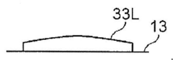
- the height of the rib 33L from the left wall 13 increases from both ends in the longitudinal direction of the rib toward the center in the longitudinal direction.
- the height of the rib 35L from the left wall 13 increases once as the distance from the both ends in the longitudinal direction of the rib, and decreases as it moves toward the center in the longitudinal direction.
- illustration is omitted, the same applies to the other ribs 31L, 32L, and 34L, and the height of each rib from the inner wall surface of the housing changes depending on the position in the longitudinal direction.
- the average height of the ribs 31L to 35L from the left wall 13 decreases from the center in the arrangement direction to both sides in the arrangement direction.
- the average height means the average height at each position in the longitudinal direction of the rib.
- FIGS. 3 and 4 are views for explaining a method of determining the shape of the rib in the present embodiment.
- importance is placed on measures for vibration in the first mode, which has a large contribution to radiated sound. Therefore, the inventor of the present application generated a first-order vibration mode in the speaker housing 10 provided with no rib, and obtained a stress distribution generated on each wall of the speaker housing 10 in this state.
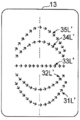
- FIGS. 3A and 4A show a stress distribution generated on the left wall 13 and the rear wall 12 when the primary mode vibration is generated.
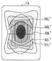
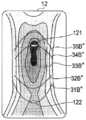
- FIGS. 3B and 4B show the distribution of Mises stress at each position on the inner wall surface of the housing in the state where the stress shown in FIGS. 3A and 4A is generated.
- the Mises stress is a scalar value of the stress.
- the Mises stress is represented by the dot density, and the higher the Mises stress is, the higher the dot density is.
- reference numerals 121 and 122 denote holes formed in the rear wall 12 for wiring extraction and the like.
- a curve or a straight line (hereinafter simply referred to as a line) in which a plurality of arrows are arranged in parallel from the lower short side of the left wall 13 and the short side of the rear wall 12 toward the upper short side.
- 31L'-35L 'and lines 31B'-35B' are shown.
- the arrows at each position of these lines schematically show the maximum principal stress at that position.
- the lines 31L 'to 35L' and the lines 31B 'to 35B' have shapes based on the direction of the maximum principal stress at each position on the wall surface of the left wall 13 or the rear wall 12.
- the wall surfaces of the left wall 13 and the rear wall 12 are divided into fine meshes (for example, meshes having a maximum outer diameter of 1 to 5 mm), and the maximum principal stress in each mesh is determined.
- the section from the upper side to the lower side of each wall is substantially equally divided into six at the center in the left-right direction of the left wall 13 and the rear wall 12, and the five division positions are each set to the initial position X0.
- a portion on the right side from each initial position X0 in the lines 31L 'to 35L' and the lines 31B 'to 35B' is obtained. Specifically, as shown in the enlarged view of FIG.
- the initial position X0 is the current position X1, the maximum principal stress in the mesh at the current position X1, the upper right position X2, the right position X3, the lower right
- the maximum principal stress in each mesh at the position X4 is compared, and the mesh in which the maximum principal stress having the closest orientation and magnitude is generated is selected.
- the selected mesh is set as the mesh at the current position, and the same processing is repeated. In this way, the shape of the portion of the lines 31L 'to 35L' and the lines 31B 'to 35B' on the right side from the initial position X0 is determined.
- the shape of the left part of the lines 31L 'to 35L' and the lines 31B 'to 35B' from the initial position X0 is determined.
- the direction of maximum principal stress is considered to be the direction in which large strain is occurring. Therefore, it is considered that if the rigidity in the direction of the maximum principal stress at which a large strain occurs is increased, the rigidity against the vibration in the first mode can be effectively increased. Therefore, in the present embodiment, a line that draws a curve or a straight line shape in which the maximum principal stress at each position on the line along the wall is continuous is determined, and a rib extending along these lines is attached to each inner wall surface of the speaker housing 10. It is fixed.
- each rib is formed on the left wall 13, the rear wall 12, and the right wall 14, respectively.
- the shape of the ribs 31L to 35L, 31B to 35B, and 31B to 35B in FIG. 1 is such that the maximum principal stress in each mesh on the line is continuous on each wall surface of the speaker housing 10 where no rib is provided. It is determined to follow a line that describes a curved or straight line shape.
- a rib (first rib) 33L disposed near the center in the vertical direction is disposed so as to extend linearly in the horizontal direction.
- the ribs (second ribs) 34L and 35L disposed above are curved so as to protrude upward.
- the ribs 32 (third ribs) L and 31L disposed below the 33L are curved so as to protrude downward.
- the ribs 31B to 35B and 31B to 35B of the other walls 12, 14 are formed in the same manner.
- the height of the rib from the inner wall surface of the housing is changed in the longitudinal direction.
- the Mises stress is non-uniform on the inner wall surface of the housing, and the Mises stress is substantially maximum at the center of the inner wall surface of the housing, and the Mises stress decreases toward the periphery of the inner wall surface of the housing. Accordingly, the Mises stress on each of the lines 31L 'to 35L' and 31B 'to 35B' where the maximum principal stresses are continuous is not uniform, and the Mises stress changes in the longitudinal direction of the line.
- the height at the position corresponding to each mesh of the ribs 31L to 35L, 31R to 35R, and 31B to 35B is set to the height corresponding to the Mises stress at the position on the inner wall surface of the housing.
- the local rigidity of the rib is made to correspond to the local Mises stress.
- the height of each rib is not particularly limited, but may be, for example, 5 to 20 mm, and preferably 10 to 15 mm. Also, the width of each rib can be the same as the height.
- FIGS. 7 to 9 are diagrams showing frequency characteristics of vibrations generated on each wall surface of the speaker housing due to sound emission in the first to third comparative examples.
- FIG. 10 is a diagram illustrating frequency characteristics of vibrations generated on each wall surface of the speaker housing due to sound emission in the speaker housing 10 according to the present embodiment. 7 to 10, the horizontal axis represents the frequency (Hz), and the vertical axis represents the average acceleration (m / s2) of the wall vibration.
- A11 is the frequency characteristic of the vibration generated on the front wall 11
- A12 is the frequency characteristic of the vibration generated on the rear wall 12
- A13 is the frequency characteristic of the vibration generated on the left wall 13
- A14 is the vibration generated on the right wall 14.
- A15 indicates the frequency characteristic of the vibration generated on the ceiling wall 15.
- the frequency at which the peak P1 of the primary vibration mode occurs is 425 Hz in the first comparative example (FIG. 7), 535 Hz in the second comparative example (FIG. 8), and the third comparative example (FIG. 8). 6, FIG. 9) and 730 Hz in the present embodiment (FIGS. 1 and 10).
- the frequency of the primary vibration mode can be significantly increased as compared with the first to third comparative examples.
- the frequency of the primary vibration mode is greatly increased without causing a significant weight of the speaker housing, and the reproduced sound of the speaker is increased. Quality degradation can be suppressed.
- the height of each rib is changed in the longitudinal direction of the rib in order to obtain rigidity corresponding to the local Mises stress at a position corresponding to each mesh of the rib.
- the width of the rib may be changed in the longitudinal direction of the rib as illustrated in FIG.
- both the height and the width of the rib may be changed in the longitudinal direction of the rib. That is, at least one of the height and the width of the rib may be changed in the longitudinal direction of the rib.
- the number of ribs is not limited to this, and the number of ribs is more than five or less than five. May be fixed. Further, a different number of ribs may be fixed for each inner wall surface.
- the ribs near the center in the vertical direction are formed in a straight line, the ribs above it are curved so as to be convex upward, and the ribs below it are convex downward.
- the present invention is not limited to this.
- two or more linear ribs may or may not be provided.
- the linear ribs can be arranged other than near the center in the vertical direction.
- all the ribs can be formed so as to be curved downwardly or upwardly. That is, at least some of the ribs arranged in parallel may be curved.
- the radius of curvature of each rib is not particularly limited.
- the ribs are fixed on the inner wall surface of the speaker housing.
- the installation mode of the ribs is not limited to “fixed”.
- the ribs may be formed on the inner wall surface by excavation or the like.
- the rib is formed so as to extend substantially in the horizontal direction.
- the rib may be provided substantially along the vertical direction.
- a plurality of directions such as a substantially horizontal direction and a substantially vertical direction can be mixed as directions in which the plurality of ribs extend.
- the direction in which the ribs extend is determined based on the principal stress when the primary mode vibration is generated. For example, secondary mode, tertiary mode and other higher mode vibrations are generated.
- the direction in which the ribs extend can also be determined based on the main stress at the time of the application. For example, in the example shown in FIG. 12, the ribs are formed based on the main stress generated when the secondary mode vibration is generated. Therefore, various ribs can be formed based on the direction of the generated main stress regardless of the mode of vibration.
- the shape of the speaker housing is not limited to the rectangular parallelepiped as in the above embodiment, and various forms are possible. That is, the internal space may be formed by a plurality of other walls in addition to the front wall on which the speaker unit is mounted, and the rib may be formed on at least a part of the plurality of other walls.
Landscapes
- Physics & Mathematics (AREA)
- Engineering & Computer Science (AREA)
- Acoustics & Sound (AREA)
- Signal Processing (AREA)
- Health & Medical Sciences (AREA)
- Otolaryngology (AREA)
- Details Of Audible-Bandwidth Transducers (AREA)
Abstract
本発明に係るスピーカ筐体は、スピーカユニットが、取り付けられる前面壁と、少なくとも1つの第1壁と、少なくとも1つの第2壁と、前記各第1壁に取り付けられる、複数のリブと、を備え、前記前面壁、前記第1壁、及び前記第2壁によって内部空間が形成され、前記第1壁を区切る複数のメッシュを規定し、前記第1壁において、前記リブが設けられていない状態で振動が生じたときに、当該振動によって前記各メッシュに発生する最大主応力の方向に基づいて、前記リブの形状が決定されている。
Description
この発明は、スピーカ筐体に関する。
スピーカでは、放音によりスピーカ筐体に振動が発生する。このスピーカ筐体の振動は、スピーカの再生音の品質に重要な影響を与える。そこで、スピーカ筐体の剛性を高めて、再生音の品質を制御する技術が提供されている。
特許文献1に開示の技術では、スピーカ筐体の内壁の表面に複数のリブを設けている。ここで、各リブは筐体の奥行き方向に延びた直線形状をなしており、各リブの寸法は異なっている。この技術によれば、スピーカ筐体の振動モードを変化させることにより、スピーカの音質を変化、向上させることができる。
特許文献2に開示の技術では、スピーカ筐体の内壁に凹凸部を設ける。ここで、凹凸形状は平面視で円、楕円、矩形、長方形、直線状、曲線状、波線状などの形状である。このような凹凸の繰り返しを設けることにより、スピーカ筐体をなす板材全体の厚みを増加しなくても、スピーカ筐体の剛性を高め、板材の実質上の振動スパンを短くして共振現象を抑制することができる。
特許文献1および2に開示されているようにスピーカ筐体の内壁にリブや凹凸を設けると、スピーカ筐体の剛性が向上し、スピーカ筐体の振動を抑制することができる。しかし、特許文献1および2に開示の技術は、スピーカ筐体に発生する振動のうち再生音の品質に影響を与える特定モードの振動に的を絞って剛性を高めるものではない。このため、再生音の品質劣化を抑制するために、スピーカ筐体に発生し得る広範囲の振動モードを対象として、強い剛性の得られる大規模なリブや凹凸を設ける必要があり、スピーカ筐体の重量の増加の要因となっていた。
この発明は以上のような事情に鑑みてなされたものであり、スピーカ筐体の重量の増加を回避しつつ特定モードの振動に対する剛性を高め、再生音の品質劣化を抑制する技術的手段を提供することを目的とする。
本発明に係る第1のスピーカ筐体は、スピーカユニットが、取り付けられる前面壁と、少なくとも1つの第1壁と、少なくとも1つの第2壁と、前記各第1壁面に設けられる、複数のリブと、を備え、前記前面壁、前記第1壁、及び前記第2壁によって内部空間が形成され、前記第1壁を区切る複数のメッシュを規定し、前記第1壁において、前記リブが設けられていない状態で振動が生じたときに、当該振動によって前記各メッシュに発生する最大主応力の方向に基づいて、前記リブの形状が決定されている。
本発明に係る第2のスピーカ筐体は、スピーカユニットが、取り付けられる前面壁と、少なくとも1つの第1壁と、少なくとも1つの第2壁と、前記各第1壁面に設けられる、複数のリブと、を備え、前記前面壁、前記第1壁、及び前記第2壁によって内部空間が形成され、前記複数のリブは、略平行に第1方向に並べられ、前記複数のリブの少なくとも一部は、前記第1方向の両側のいずれか一方に凸となるように湾曲している。
以下、図面を参照し、この発明の実施形態について説明する。
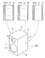
図1はこの発明の一実施形態であるスピーカ筐体10の構成を示す図である。このスピーカ筐体10は、前面壁11と、この前面壁11と対向する背面壁12と、前面壁11および背面壁12間の内部空間を左右から挟む左面壁13および右面壁14と、同内部空間を上下から挟む天井壁15および床壁16とを有する。前面壁11は、スピーカユニットを収容する孔21および22が形成されている。
そして、左面壁13の内壁面には、形状の異なる複数本のリブ31L~35Lが略平行に並んで固定されている。ここで、リブ31L~35Lは、左面壁13の下側の短辺から上側の短辺に向かう方向に並んでいる。
リブ33Lは、リブ31L~35Lの略中央に位置し、平面視において左面壁13の上下の天井壁15および床壁16に平行な直線形状をなしている。また、リブ33Lの上側に並んだリブ34Lおよび35Lは、平面視において上側に膨らんだ曲線形状、具体的には円弧形状をなしている。また、リブ33Lの下側に並んだリブ32Lおよび31Lは、平面視において下側に膨らんだ曲線形状、具体的には円弧形状をなしている。すなわち、リブ31L~35Lは、リブ33Lを中心としてリブの並べられた方向に膨らんだリブ34Lおよび35Lとリブ32Lおよび31Lとを含む。また、リブ35Lの曲率半径はリブ34Lの曲率半径よりも小さく、リブ31Lの曲率半径はリブ32Lの曲率半径より小さい。各リブ31L~35Lは、並び方向中央付近のリブ(具体的にはリブ33L)から並び方向両側のリブ(具体的にはリブ35Lおよび31L)に向かう程、曲率半径が小さくなる。
右面壁14の内壁面にも、リブ31L~35Lと同様な形状のリブ31R~35Rが上下方向に並んで固定されている。背面壁12の内壁面にも、リブ31L~35Lと同様な形状のリブ31B~35Bが上下方向に並んで固定されている。
本実施形態において、各リブの筐体内壁面からの高さは、長手方向の位置により変化する。図2Aは左面壁13に固定されたリブ33Lを左面壁13に平行な方向から見た図である。また、図2Bは左面壁13に固定されたリブ35Lを左面壁13に平行な方向から見た図である。
図2Aに示すように、リブ33Lの左面壁13からの高さは、リブの長手方向両端から長手方向中央に向かうに従って高くなっている。また、図2Bに示すように、リブ35Lの左面壁13からの高さは、リブの長手方向両端から離れるに従って一旦高くなり、長手方向中央に向かうに従って低くなる。図示は省略したが、他のリブ31L、32L、34Lも同様であり、各リブの筐体内壁面からの高さは、長手方向の位置により変化する。右面壁14のリブ31R~35R、背面壁12のリブ31B~35Bも同様である。
また、本実施形態では、リブ31L~35Lの左面壁13からの平均的な高さは、並び方向中央から並び方向両側に向かうに従って低くなっている。右面壁14のリブ31R~35R、背面壁12のリブ31B~35Bも同様である。ここで、平均的な高さとは、リブの長手方向の各位置での高さの平均的な高さを意味する。
図3および図4は本実施形態におけるリブの形状の決定方法を説明する図である。スピーカ筐体の振動対策では、放射音寄与の大きい1次モードの振動対策が重要視されている。そこで、本願発明者は、リブが設けられていないスピーカ筐体10に1次の振動モードを発生させ、この状態においてスピーカ筐体10の各壁に発生する応力分布を求めた。図3Aおよび図4Aは、1次モードの振動を発生させた場合に左面壁13および背面壁12に発生する応力分布を示している。図3Bおよび図4Bは、図3Aおよび図4Aの応力が発生している状態における筐体内壁面の各位置におけるミーゼス応力の分布を示している。ここで、ミーゼス応力は、応力のスカラー値である。図3Bおよび図4Bではミーゼス応力がドットの密度により表現されており、ミーゼス応力の高い領域程、ドットの密度が高くなっている。なお、図4Aおよび図4Bにおいて、121および122は、配線取り出し等のために背面壁12に形成された孔を示している。
図3Aおよび図4Aには左面壁13および背面壁12の下側の短辺から上側の短辺に向かって略平行に並び、複数の矢印を連鎖させた曲線または直線(以下、単に線という)31L’~35L’および線31B’~35B’が示されている。これらの線の各位置における矢印は、当該位置における最大主応力を模式的に示している。これらの線31L’~35L’および線31B’~35B’は、左面壁13または背面壁12の壁面上の各位置における最大主応力方向に基づく形状からなる。具体的には、線31L’~35L’および線31B’~35B’は、左面壁13または背面壁12において、線上の各位置における最大主応力方向が連続するように形状が決定されている。線31L’~35L’および線31B’~35B’の決定方法に関しては各種の方法が考えられるが、例えば次のように決定してもよい。
まず、左面壁13および背面壁12の壁面を微細なメッシュ(例えば、最大外径が、1~5mmのメッシュ)に区切り、各メッシュにおける最大主応力を求める。次に、図5に示すように、左面壁13および背面壁12の左右方向中央において、各壁の上辺から下辺までの区間を略均等に6分割し、5個の分割位置を各々初期位置X0とする。次に線31L’~35L’および線31B’~35B’における各初期位置X0から右側の部分を求める。具体的には、図5の拡大図に示すように、初期位置X0を現在位置X1とし、現在位置X1のメッシュにおける最大主応力と、当該メッシュの右上の位置X2、右側の位置X3、右下の位置X4の各メッシュにおける最大主応力を比較し、向きおよび大きさが最も近い最大主応力の発生しているメッシュを選択する。この選択したメッシュを現在位置のメッシュとし、同様の処理を繰り返す。このようにして、線31L’~35L’および線31B’~35B’のうち初期位置X0から右側の部分の形状が決定される。同様の処理により線31L’~35L’および線31B’~35B’のうち初期位置X0から左側の部分の形状が決定される。
ここで、応力と歪は比例関係にあるので、最大主応力方向は大きな歪が発生している方向であると考えられる。従って、大きな歪が発生する最大主応力方向の剛性を高めれば1次モードの振動に対する剛性を効果的に高めることができると考えられる。そこで、本実施形態では、壁に沿った線上の各位置における最大主応力が連続する曲線または直線形状を描く線を求め、これらの線に沿って延びるリブをスピーカ筐体10の各内壁面に固定しているのである。
すなわち、図1に示すように、左面壁13、背面壁12、及び右面壁14には、それぞれ5本ずつのリブが形成されている。そして、図1におけるリブ31L~35L、31B~35Bおよび31B~35Bの形状は、このようにリブが設けられていないスピーカ筐体10の各壁面において、線上の各メッシュにおける最大主応力が連続する曲線または直線形状を描く線に沿うように決定されている。
具体的には、例えば、図1の左面壁13では、上下方向の中央付近に配置されているリブ(第1リブ)33Lは水平方向に直線状に延びるように配置されており、このリブ33Lよりも上に配置されているリブ(第2リブ)34L,35Lは上に凸となるように湾曲している。一方、33Lよりも下に配置されているリブ32(第3リブ)L,31Lは、下に凸となるように湾曲している。そして、他の壁12,14のリブ31B~35B,31B~35Bも同様に形成されている。
また、上述したように、本実施形態ではリブの筐体内壁面からの高さを長手方向において変化させている。以下、その理由を説明する。
図3Bおよび図4Bに示すように、筐体内壁面においてミーゼス応力は不均一であり、概略、筐体内壁面中央においてミーゼス応力は最大となり、筐体内壁面周辺に向かうに従ってミーゼス応力は低くなる。従って、最大主応力が連続する線31L’~35L’、31B’~35B’の各線上におけるミーゼス応力も均一ではなく、ミーゼス応力は、線の長手方向において変化する。
図3Bには、図3Bに示された線31L’~35L’に対応した線31L’’~35L’’が示され、図4Bには図4Aに示された線31B’~35B’に対応した線31B’’~35B’’が各々示されている。図3Bによると、例えば線33L’’上の各メッシュのミーゼス応力は、線33L’’の左端から中央に向かうに従って上昇し、中央から右端に向かうに従って低下する。また、線35L’’上のミーゼス応力は、線35L’’の左端から右に向かうに従って一旦上昇し、そこから中央に向かうに従って低下し、中央から右に向かうに従って一旦上昇し、そこから右端に向かうに従って低下する。
ここで、特定モードでの振動に対する剛性を十分に高めるためには、各メッシュに局所的に発生するミーゼス応力に応じた剛性を、リブの各メッシュと対応する位置に持たせるのが効果的であると考えられる。そこで、本実施形態では、リブ31L~35L、31R~35R、31B~35Bの各々の各メッシュと対応する位置での高さを筐体内壁面における当該位置でのミーゼス応力に応じた高さとすることにより、リブの局所的な剛性を局所的なミーゼス応力に対応させている。なお、各リブの高さは、特には限定されないが、例えば、5~20mmとすることができ、10~15mmとすることが好ましい。また、各リブの幅も、高さと同様にすることができる。
次に、本実施形態の効果を以下の第1~第3比較例との比較において説明する。第1比較例は、リブが設けられていない通常のスピーカ筐体であり、左面壁及び右面壁の板厚は5mmである。この板厚については、本実施形態、及び第3比較例においても同じである。第2比較例は、第1比較例の左面壁、右面壁の板厚を2mm増加させたスピーカ筐体である。第3比較例は、図6に示すように、上下方向に延びた平行な複数本のリブ40を左面壁13、右面壁14および背面壁12の各内壁面に固定したスピーカ筐体10Bである。リブ40の内壁面からの高さは5mmであり、幅は5mmである。本実施形態によるスピーカ筐体10は、基本的に前掲図1に示す構成の筐体であるが、リブ31L~35L、31R~35R、31B~35Bの高さは長手方向の位置に応じて変化させず、一律5mmとし、幅も5mmとした。
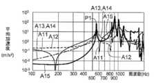
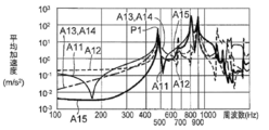
図7~図9は第1~第3比較例において放音によりスピーカ筐体の各壁面に発生する振動の周波数特性を示す図である。そして、図10は本実施形態によるスピーカ筐体10において放音によりスピーカ筐体の各壁面に発生する振動の周波数特性を示す図である。これらの図7~図10において、横軸は周波数(Hz)、縦軸は壁の振動の平均加速度(m/s2)である。そして、A11は前面壁11に発生する振動の周波数特性、A12は背面壁12に発生する振動の周波数特性、A13は左面壁13に発生する振動の周波数特性、A14は右面壁14に発生する振動の周波数特性、A15は天井壁15に発生する振動の周波数特性を示している。
図7~図10によると、1次の振動モードのピークP1が発生する周波数は、第1比較例(図7)では425Hz、第2比較例(図8)では535Hz、第3比較例(図6、図9)では485Hz、本実施形態(図1、図10)では730Hzとなっている。このように本実施形態によれば、1次の振動モードの周波数を第1~第3比較例に比べて大幅に上昇させることができる。また、本実施形態によれば、第2比較例や第3比較例と比べ、スピーカ筐体の大幅な重量を招くことなく、1次の振動モードの周波数を大幅に上昇させ、スピーカの再生音の品質劣化を抑制することができる。
以上、この発明の一実施形態について説明したが、この発明には他にも実施形態があり得る。例えば次の通りである。なお、以下の例は、1つ以上を組み合わせることができる。
(1)上記実施形態では、リブの各メッシュに対応する位置において局所的なミーゼス応力に応じた剛性を得るために、各リブの高さを当該リブの長手方向において変化させた。しかし、そのようにする代わりに、図11に例示するように、リブの幅を当該リブの長手方向において変化させてもよい。あるいはリブの高さおよび幅の両方を当該リブの長手方向において変化させてもよい。すなわち、リブの高さまたは幅の少なくとも一方の寸法を当該リブの長手方向において変化させてもよい。
(2)上記実施形態では、スピーカ筐体10の左面壁13、右面壁14、背面壁12にリブを固定したが、他の壁にもリブを固定、あるいは全ての壁にリブを固定してもよい。すなわち、左面壁13、右面壁14、背面壁12、天面壁15、床壁16のうちの、一以上の壁にリブを設けることもできる。また、全ての壁にリブを設けることができるため、本発明に係る第2壁にもリブを設けることもできる。
(3)上記実施形態では、1つの内壁面に5本のリブを固定したが、リブの本数はこれに限定されるものではなく、5本より多い本数のリブあるいは5本より少ない本数のリブを固定してもよい。また、内壁面毎に異なる本数のリブを固定してもよい。また、上記実施形態では、上下方向の中央付近のリブを直線状に形成し、それよりも上のリブを上に凸となるように湾曲させ、それよりも下のリブを下に凸となるように湾曲させているが、これに限定されない。例えば、直線状のリブを2以上設けてもよいし、あるいは設けなくてもよい。また、直線状のリブは、上下方向の中央付近以外に配置することもできる。また、全てのリブを下に凸、または上に凸に湾曲するように形成することもできる。すなわち、平行に並ぶ複数のリブのうち、少なくとも一部のリブが湾曲していればよい。また、各リブの曲率半径も特には限定されない。
(4)上記実施形態では、スピーカ筐体の内壁面上にリブを固定したが、リブの設置態様は“固定”に限定されるものではない。例えば掘削等によりリブを内壁面に形成してもよい。
(5)上記実施形態では、略水平方向に延びるようにリブが形成されているが、各メッシュでの主応力の方向にしたがうのであれば、略上下方向に沿ってリブを設けることもできし、複数のリブの延びる方向として、略水平方向、略上下方向などの複数の方向を混在させることもできる。
上記実施形態では、リブの延びる方向を決定する際、隣接するメッシュの主応力の方向及び大きさが近くなるように、メッシュを選択しているが、これに限定されない。すなわち、全ての隣接するメッシュにおいて、主応力の方向及び大きさが近くなくてもよく、一部の隣接するメッシュにおいては、方向や大きさが多少異なっていてもよく、このように選択したメッシュにしたがって、リブの延びる方向を決定してもよい。また、リブは、連続していなくてもよく、リブの延びる方向において、所定間隔をおいて配置することもできる。
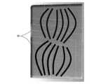
上記実施形態では、一次モードの振動を発生させたときの主応力に基づいて、リブの延びる方向を決定しているが、例えば、二次モード、三次モード等の高次のモードの振動を発生させたときの主応力に基づいて、リブの延びる方向を決定することもできる。例えば、図12に示す例では、二次モードの振動を発生されたときに生じる主応力に基づいてリブを形成している。したがって、振動のモードにかかわらず、発生した主応力の方向に基づいて、種々のリブを形成することができる。
スピーカ筐体の形状は、上記実施形態のような直方体に限定されず、種々の形態が可能である。すなわち、スピーカユニットが取り付けられる前面壁のほか、複数の他の壁によって内部空間が形成されていればよく、複数の他の壁の少なくとも一部に上記リブが形成されていればよい。
10……スピーカ筐体、11……前面壁、12……背面壁、13……左面壁、14……右面壁、15……天井壁、16……床壁、31L~35L,31R~35R,31B~35B……リブ。
Claims (12)
- スピーカユニットが、取り付けられる前面壁と、
少なくとも1つの第1壁と、
少なくとも1つの第2壁と、
前記各第1壁に設けられる、複数のリブと、
を備え、
前記前面壁、前記第1壁、及び前記第2壁によって内部空間が形成され、
前記第1壁を区切る複数のメッシュを規定し、
前記第1壁において、前記リブが設けられていない状態で振動が生じたときに、当該振動によって前記各メッシュに発生する最大主応力の方向に基づいて、前記リブの形状が決定されている、スピーカ筐体。 - 前記各リブは、隣接する前記メッシュに生じる最大主応力の方向を連結した、連続する曲線または直線形状である、請求項1に記載のスピーカ筐体。
- 前記各リブは、最大主応力の向き及び大きさが最も近い隣接するメッシュ同士を連結する方向に延びている、請求項1または2に記載のスピーカ筐体。
- 前記振動によって前記各メッシュに発生するミーゼス応力に応じて、前記各リブの前記各メッシュと対応する位置での高さが決定されている、請求項1から3のいずれかに記載のスピーカ筐体。
- 前記振動によって前記各メッシュに発生するミーゼス応力に応じて、前記各リブの前記各メッシュと対応する位置での幅が決定されている、請求項1から3のいずれかに記載のスピーカ筐体。
- 前記振動は、一次モードの振動である、請求項1から5のいずれかに記載のスピーカ筐体。
- スピーカユニットが、取り付けられる前面壁と、
少なくとも1つの第1壁と、
少なくとも1つの第2壁と、
前記各第1壁に設けられる、複数のリブと、
を備え、
前記前面壁、前記第1壁、及び前記第2壁によって内部空間が形成され、
前記複数のリブは、略平行に第1方向に並べられ、
前記複数のリブの少なくとも一部は、前記第1方向の両側のいずれか一方に凸となるように湾曲している、スピーカ筐体。 - 前記複数のリブの少なくとも一部は、前記第1方向の中央付近から離れるにしたがって、曲率半径が小さくなるように設けられている、請求項7に記載のスピーカ筐体。
- 前記複数のリブは、
直線状に延びる第1リブと、
前記第1リブから前記第1方向の一方側に配置され、当該一方側に凸となるように湾曲する少なくとも1つの第2リブと、
前記第1リブから前記第1方向の他方側に配置され、当該他方側に凸となるように湾曲する少なくとも1つの第3リブと、
を備えている、請求項7または8に記載のスピーカ筐体。 - 前記複数のリブは、前記第1方向の中央付近に近い前記リブほど、当該リブの幅及び高さの少なくとも一方が、大きくなるように設けられている、請求項7から9のいずれかに記載のスピーカ筐体。
- 前記各リブは、当該リブが延びる方向に沿って、幅及び高さの少なくとも一方が変化するように設けられている、請求項7から10のいずれかに記載のスピーカ筐体。
- 前記複数のリブは、前記第1方向と直交する方向が、水平方向である、請求項7から11のいずれかに記載のスピーカ筐体。
Priority Applications (2)
| Application Number | Priority Date | Filing Date | Title |
|---|---|---|---|
| JP2020546229A JP7044166B2 (ja) | 2018-09-14 | 2019-09-13 | スピーカ筐体 |
| US17/200,036 US11395053B2 (en) | 2018-09-14 | 2021-03-12 | Speaker housing |
Applications Claiming Priority (2)
| Application Number | Priority Date | Filing Date | Title |
|---|---|---|---|
| JP2018-172549 | 2018-09-14 | ||
| JP2018172549 | 2018-09-14 |
Related Child Applications (1)
| Application Number | Title | Priority Date | Filing Date |
|---|---|---|---|
| US17/200,036 Continuation US11395053B2 (en) | 2018-09-14 | 2021-03-12 | Speaker housing |
Publications (1)
| Publication Number | Publication Date |
|---|---|
| WO2020054854A1 true WO2020054854A1 (ja) | 2020-03-19 |
Family
ID=69777737
Family Applications (1)
| Application Number | Title | Priority Date | Filing Date |
|---|---|---|---|
| PCT/JP2019/036150 Ceased WO2020054854A1 (ja) | 2018-09-14 | 2019-09-13 | スピーカ筐体 |
Country Status (3)
| Country | Link |
|---|---|
| US (1) | US11395053B2 (ja) |
| JP (1) | JP7044166B2 (ja) |
| WO (1) | WO2020054854A1 (ja) |
Families Citing this family (1)
| Publication number | Priority date | Publication date | Assignee | Title |
|---|---|---|---|---|
| KR102488251B1 (ko) * | 2022-07-26 | 2023-01-13 | (주)드림스토리뮤직 | 오디오 입체음향을 웹툰에 접목한 녹음 시스템 |
Citations (4)
| Publication number | Priority date | Publication date | Assignee | Title |
|---|---|---|---|---|
| JPS60230797A (ja) * | 1984-04-28 | 1985-11-16 | Mitsumoto Shokai:Kk | スピ−カ−ボツクス |
| JPS6144986U (ja) * | 1984-08-29 | 1986-03-25 | 株式会社東芝 | スピ−カ装置 |
| JPH11289589A (ja) * | 1998-04-01 | 1999-10-19 | Sony Corp | 面剛性強化成形品及びこれを応用したスピーカーボックス |
| JP2007123963A (ja) * | 2005-10-25 | 2007-05-17 | Onkyo Corp | スピーカーキャビネットおよびこれを用いたスピーカーシステム |
Family Cites Families (6)
| Publication number | Priority date | Publication date | Assignee | Title |
|---|---|---|---|---|
| US3953675A (en) * | 1972-05-08 | 1976-04-27 | Babbco, Ltd. | Audio speaker system |
| US4168762A (en) * | 1978-01-13 | 1979-09-25 | Amanita Sound, Inc. | Loudspeaker enclosure |
| JPS5846613U (ja) | 1981-09-28 | 1983-03-29 | カルソニックカンセイ株式会社 | 自動車用空気調和装置のユニツト取付構造 |
| JPH06448Y2 (ja) | 1987-08-18 | 1994-01-05 | 山形日本電気株式会社 | 薄膜形成装置の遮蔽板 |
| US20060225950A1 (en) * | 2003-12-08 | 2006-10-12 | Hiroyuki Ishida | Speaker cabinet |
| TWI536850B (zh) * | 2013-07-29 | 2016-06-01 | 雅瑟音響股份有限公司 | 音箱及其製造方法 |
-
2019
- 2019-09-13 WO PCT/JP2019/036150 patent/WO2020054854A1/ja not_active Ceased
- 2019-09-13 JP JP2020546229A patent/JP7044166B2/ja active Active
-
2021
- 2021-03-12 US US17/200,036 patent/US11395053B2/en active Active
Patent Citations (4)
| Publication number | Priority date | Publication date | Assignee | Title |
|---|---|---|---|---|
| JPS60230797A (ja) * | 1984-04-28 | 1985-11-16 | Mitsumoto Shokai:Kk | スピ−カ−ボツクス |
| JPS6144986U (ja) * | 1984-08-29 | 1986-03-25 | 株式会社東芝 | スピ−カ装置 |
| JPH11289589A (ja) * | 1998-04-01 | 1999-10-19 | Sony Corp | 面剛性強化成形品及びこれを応用したスピーカーボックス |
| JP2007123963A (ja) * | 2005-10-25 | 2007-05-17 | Onkyo Corp | スピーカーキャビネットおよびこれを用いたスピーカーシステム |
Also Published As
| Publication number | Publication date |
|---|---|
| US20210329357A1 (en) | 2021-10-21 |
| US11395053B2 (en) | 2022-07-19 |
| JPWO2020054854A1 (ja) | 2021-03-25 |
| JP7044166B2 (ja) | 2022-03-30 |
Similar Documents
| Publication | Publication Date | Title |
|---|---|---|
| US11006194B2 (en) | Grille and acoustic device | |
| JP6413594B2 (ja) | 電子機器のスピーカボックス構造 | |
| US10021480B2 (en) | Integrated speakers | |
| US20170066313A1 (en) | Vehicle vibration suppressing structure | |
| EP3952326B1 (en) | Headphone reducing standing wave | |
| JP7044166B2 (ja) | スピーカ筐体 | |
| US9214148B2 (en) | Acoustic structure | |
| US10951977B2 (en) | Speaker | |
| GB2575356A (en) | Diaphragm structure for loudspeaker | |
| JP2016211344A (ja) | 防音壁設備 | |
| JP5263375B2 (ja) | アンダーカバー | |
| JP2022182800A (ja) | スピーカ用振動板およびスピーカ | |
| JP7234731B2 (ja) | 吸音部材 | |
| JP6027847B2 (ja) | 床構造 | |
| JP2009287436A (ja) | オイルパン | |
| CN219107658U (zh) | 一种车载功放 | |
| JP2008291557A (ja) | 遮音パネル | |
| JP2015204539A (ja) | スピーカー装置 | |
| JP7255365B2 (ja) | 壁体補強構造及び筐体 | |
| EP4472236A1 (en) | Acoustic output device | |
| US20250024196A1 (en) | Sound output device | |
| JP7178690B2 (ja) | 音響建造物 | |
| JP2020027189A (ja) | 吸音部材、建築パネル及び吸音筐体 | |
| JP2009290346A (ja) | パネルスピーカ装置 | |
| JP6647835B2 (ja) | 強度補強用金属板材 |
Legal Events
| Date | Code | Title | Description |
|---|---|---|---|
| 121 | Ep: the epo has been informed by wipo that ep was designated in this application |
Ref document number: 19859960 Country of ref document: EP Kind code of ref document: A1 |
|
| ENP | Entry into the national phase |
Ref document number: 2020546229 Country of ref document: JP Kind code of ref document: A |
|
| NENP | Non-entry into the national phase |
Ref country code: DE |
|
| 122 | Ep: pct application non-entry in european phase |
Ref document number: 19859960 Country of ref document: EP Kind code of ref document: A1 |