WO2020054748A1 - 燃焼装置及びボイラ - Google Patents
燃焼装置及びボイラ Download PDFInfo
- Publication number
- WO2020054748A1 WO2020054748A1 PCT/JP2019/035616 JP2019035616W WO2020054748A1 WO 2020054748 A1 WO2020054748 A1 WO 2020054748A1 JP 2019035616 W JP2019035616 W JP 2019035616W WO 2020054748 A1 WO2020054748 A1 WO 2020054748A1
- Authority
- WO
- WIPO (PCT)
- Prior art keywords
- ammonia
- cylinder nozzle
- nozzle
- pulverized coal
- fuel
- Prior art date
- Legal status (The legal status is an assumption and is not a legal conclusion. Google has not performed a legal analysis and makes no representation as to the accuracy of the status listed.)
- Ceased
Links
Images



Classifications
-
- F—MECHANICAL ENGINEERING; LIGHTING; HEATING; WEAPONS; BLASTING
- F23—COMBUSTION APPARATUS; COMBUSTION PROCESSES
- F23C—METHODS OR APPARATUS FOR COMBUSTION USING FLUID FUEL OR SOLID FUEL SUSPENDED IN A CARRIER GAS OR AIR
- F23C1/00—Combustion apparatus specially adapted for combustion of two or more kinds of fuel simultaneously or alternately, at least one kind of fuel being either a fluid fuel or a solid fuel suspended in a carrier gas or air
- F23C1/12—Combustion apparatus specially adapted for combustion of two or more kinds of fuel simultaneously or alternately, at least one kind of fuel being either a fluid fuel or a solid fuel suspended in a carrier gas or air gaseous and pulverulent fuel
-
- F—MECHANICAL ENGINEERING; LIGHTING; HEATING; WEAPONS; BLASTING
- F23—COMBUSTION APPARATUS; COMBUSTION PROCESSES
- F23D—BURNERS
- F23D1/00—Burners for combustion of pulverulent fuel
-
- F—MECHANICAL ENGINEERING; LIGHTING; HEATING; WEAPONS; BLASTING
- F23—COMBUSTION APPARATUS; COMBUSTION PROCESSES
- F23D—BURNERS
- F23D17/00—Burners for combustion simultaneously or alternately of gaseous or liquid or pulverulent fuel
- F23D17/005—Burners for combustion simultaneously or alternately of gaseous or liquid or pulverulent fuel gaseous or pulverulent fuel
-
- F—MECHANICAL ENGINEERING; LIGHTING; HEATING; WEAPONS; BLASTING
- F23—COMBUSTION APPARATUS; COMBUSTION PROCESSES
- F23K—FEEDING FUEL TO COMBUSTION APPARATUS
- F23K3/00—Feeding or distributing of lump or pulverulent fuel to combustion apparatus
-
- F—MECHANICAL ENGINEERING; LIGHTING; HEATING; WEAPONS; BLASTING
- F23—COMBUSTION APPARATUS; COMBUSTION PROCESSES
- F23D—BURNERS
- F23D2204/00—Burners adapted for simultaneous or alternative combustion having more than one fuel supply
- F23D2204/20—Burners adapted for simultaneous or alternative combustion having more than one fuel supply gaseous and pulverulent fuel
Definitions
- the present disclosure relates to a combustion device and a boiler. This application claims priority based on Japanese Patent Application No. 2018-169624 for which it applied to Japan on September 11, 2018, and uses the content here.
- Patent Document 1 discloses a combined energy system that burns a fuel containing ammonia. This combined energy system burns natural gas, which is the main fuel, by adding ammonia to the fuel for the purpose of reducing carbon dioxide emissions.
- nitrogen oxide (NOx) contained in the combustion gas may increase.
- a carbon fuel such as natural gas and a nitrogen-containing fuel such as ammonia together, it is necessary to suppress an increase in nitrogen oxides.
- the present disclosure has been made in view of the above circumstances, and has an object to suppress an increase in nitrogen oxides in a combustion device and a boiler that burn ammonia as fuel.
- a combustion device is a combustion device that is installed in a furnace and injects and burns ammonia as fuel, and is disposed at a central portion when viewed from the fuel injection direction and injects the ammonia. And an outer cylinder nozzle that is disposed so as to surround the inner cylinder nozzle from the radial outside when viewed from the fuel injection direction, and that injects the ammonia around the inner cylinder nozzle.
- the combustion device may further include a swirler disposed inside the outer cylinder nozzle and configured to swirl the flow of the ammonia injected around the inner cylinder nozzle.
- the combustion device of the above aspect may further include a pulverized coal injection nozzle for injecting air containing pulverized coal around the outer cylinder nozzle as viewed from the fuel injection direction.
- the pulverized coal injection nozzle is arranged so as to surround the outer cylinder nozzle from a radially outer side when viewed from the fuel injection direction, and between the outer wall surface of the outer cylinder nozzle and the outer cylinder nozzle. It may have a single pipe structure for guiding air containing pulverized coal.
- the pulverized coal injection nozzle may include an inner pipe that is disposed so as to surround the outer cylinder nozzle from a radially outer side when viewed from the fuel injection direction, and the inner pipe that is viewed from the fuel injection direction. It may have a double pipe structure having an inner pipe which is arranged to surround the inner pipe from the radial outside and guides the air containing the pulverized coal between the inner pipe and the inner pipe.
- a boiler according to one embodiment of the present disclosure includes the above-described combustion device and a furnace to which the above-described combustion device is attached.
- a first flow rate adjustment unit that adjusts a flow rate of the ammonia supplied to the inner cylinder nozzle and a second flow rate adjustment unit that adjusts a flow rate of the ammonia supplied to the outer cylinder nozzle are further provided. You may have.
- the ammonia injected from the inner cylinder nozzle forms a reduction region where the ammonia concentration is high and the oxygen concentration is low in the center of the flame when viewed from the fuel injection direction.
- the nitrogen oxides generated by the ammonia injected from the outer cylinder nozzle to the periphery of the inner cylinder nozzle mixed with oxygen and combusted ride on the circulating flow that recirculates from the outer edge of the flame toward the center. And supplied to the reduction zone.
- the nitrogen oxides generated at the outer edge of the flame are reduced in the reduction region formed by the ammonia injected from the inner cylinder nozzle, and become nitrogen gas (N 2 ). Therefore, according to the present disclosure, it is possible to suppress an increase in nitrogen oxides in a combustion device and a boiler that burn ammonia as fuel.
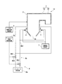
- FIG. 1 is a schematic diagram illustrating a configuration of a main part of a boiler according to a first embodiment of the present disclosure. It is a sectional view showing typically the schematic structure of the burner with which the boiler in a 1st embodiment of this indication is provided.
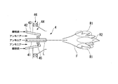
- FIG. 2 is a schematic diagram including a flame formed by a burner provided in the boiler according to the first embodiment of the present disclosure. It is sectional drawing which shows typically the schematic structure of the burner with which the boiler in 2nd Embodiment of this indication is provided. It is a mimetic diagram showing the important section composition of the boiler in a 3rd embodiment of this indication.
- FIG. 1 is a schematic diagram illustrating a main configuration of a boiler 1 according to the first embodiment.
- the boiler 1 includes a furnace 2, a flue 3, a burner 4 (combustion device), a two-stage combustion air supply unit 5, an ammonia supply unit 6, and a pulverized coal supply unit 7.
- a furnace 2 As shown in FIG. 1, the boiler 1 includes a furnace 2, a flue 3, a burner 4 (combustion device), a two-stage combustion air supply unit 5, an ammonia supply unit 6, and a pulverized coal supply unit 7.
- a furnace 2 includes a furnace 2, a flue 3, a burner 4 (combustion device), a two-stage combustion air supply unit 5, an ammonia supply unit 6, and a pulverized coal supply unit 7.
- a pulverized coal supply unit 7 Have.
- the furnace 2 is a furnace body that is constituted by vertical and cylindrical furnace walls and that burns fuel such as ammonia or pulverized coal to generate combustion heat.
- fuel such as ammonia or pulverized coal to generate combustion heat.
- high-temperature combustion gas is generated by burning the fuel.
- a discharge port 2a for discharging ash generated by fuel combustion to the outside.
- the flue 3 is connected to the upper part of the furnace 2 and guides the combustion gas generated in the furnace 2 to the outside as exhaust gas.
- the flue 3 includes a horizontal flue 3a extending horizontally from the upper part of the furnace 2 and a rear flue 3b extending downward from an end of the horizontal flue 3a.
- the boiler 1 includes a superheater installed at an upper part of the furnace 2 or the like.
- the superheater generates steam by exchanging heat between combustion heat generated in the furnace 2 and water.
- the boiler 1 includes a reheater, a economizer, an air preheater, and the like as necessary.
- the burner 4 is arranged on the lower wall of the furnace 2.
- a plurality of burners 4 are provided in the circumferential direction of the furnace 2. Although omitted in FIG. 1, a plurality of burners 4 are also provided in the height direction of the furnace 2.
- the burner 4 is arranged two-dimensionally and opposed to the lower part of the furnace 2, and injects and burns fuel.
- the burners 4 are all composite burners that can be injected into the furnace 2 using ammonia and pulverized coal as fuel.
- the furnace 2 is provided with an ignition device for igniting the fuel (ammonia and pulverized coal) injected from the burner 4.
- the boiler 1 has a combustion air supply unit that supplies combustion air to the burner 4. The fuel (ammonia and pulverized coal) injected from each burner 4 into the furnace 2 together with the combustion air is ignited and burned by the operation of the above-described ignition device.
- the burners 4 installed in the boiler 1 need not all be composite burners as described above.
- a configuration including a burner exclusively for coal or a burner exclusively for ammonia may be employed.
- ammonia is a compound of hydrogen (H) and nitrogen (N) as shown by the molecular formula, and does not include carbon (C) as a constituent atom.
- Ammonia (low-carbon fuel) is a hydrogen carrier substance having three hydrogen atoms, similar to methane (CH 3 ), although it is known as a flame-retardant substance.
- Pulverized coal is obtained by pulverizing coal, which is a fossil fuel, to a size of about several micrometers, and is generally used as fuel for boilers. That is, ammonia is a low-carbon fuel having a lower carbon concentration than pulverized coal (carbon fuel).
- FIG. 2 is a cross-sectional view schematically illustrating a schematic configuration of the burner 4.
- the burner 4 includes an inner cylinder nozzle 41, an outer cylinder nozzle 42, and a pulverized coal injection nozzle 43, and is generally formed in a substantially cylindrical shape centered on the axis L of the inner cylinder nozzle 41.
- the rear end of the inner cylinder nozzle 41 is connected to the ammonia supply unit 6 and injects ammonia into the furnace 2 from the front end of the inner cylinder nozzle 41.
- the inner cylinder nozzle 41 is disposed at the center of the burner 4 when viewed from the direction in which the burner 4 injects ammonia.
- the outer cylinder nozzle 42 is coaxially arranged with the inner cylinder nozzle 41 so as to surround the inner cylinder nozzle 41 from the outside in the radial direction when viewed from the ammonia injection direction of the burner 4 (the direction along the axis L).
- the rear end of the outer cylinder nozzle 42 is connected to the ammonia supply unit 6 and injects ammonia around the inner cylinder nozzle 41 from the front end of the outer cylinder nozzle 42.
- the pulverized coal injection nozzle 43 is provided concentrically with the inner cylinder nozzle 41 and the outer cylinder nozzle 42 so as to surround the outer cylinder nozzle 42 from the outside in the radial direction when viewed from the ammonia injection direction of the burner 4.
- the rear end of the pulverized coal injection nozzle 43 is connected to the pulverized coal supply unit 7 and injects air containing pulverized coal into the furnace 2 from the tip of the pulverized coal injection nozzle 43. That is, in the present embodiment, the pulverized coal injection nozzle 43 has a single-pipe structure for guiding the air containing the pulverized coal to and from the outer wall surface of the outer cylinder nozzle 42.
- the burner 4 includes a secondary air supply unit 44 disposed to surround the inner cylinder nozzle 41, the outer cylinder nozzle 42, and the pulverized coal injection nozzle 43, and an ammonia swirler disposed inside the outer cylinder nozzle 42. 45 (a swirler) and an air swirler 46 disposed inside the secondary air supply unit 44.
- the secondary air supply unit 44 supplies combustion air to the flame from the radial outside.
- the ammonia swirler 45 is arranged between the inner cylinder nozzle 41 and the outer cylinder nozzle 42.
- the ammonia swirler 45 is a cascade formed by a plurality of blades arranged in a circumferential direction about the axis L.
- the ammonia swirler 45 imparts a swirl component about the axis L to the flow of ammonia flowing between the inner cylinder nozzle 41 and the outer cylinder nozzle 42.
- the ammonia injected from the outer cylinder nozzle 42 is injected so as to turn around the axis L when viewed from the injection direction.
- the air swirler 46 is a cascade formed by a plurality of wings arranged in a circumferential direction about the axis L.
- the air swirler 46 imparts a swirl component about the axis L to the flow of air flowing inside the secondary air supply unit 44.
- the air supplied from the secondary air supply unit 44 to the furnace 2 is injected so as to turn around the axis L when viewed from the injection direction of ammonia.
- ammonia is injected from the inner cylinder nozzle 41 and the outer cylinder nozzle 42, pulverized coal is injected from the pulverized coal injection nozzle 43, and air for combustion is supplied, as shown in FIG.
- a flame F is formed in front of the burner 4.
- nitrogen (N) contained in ammonia and oxygen (O) contained in air are present in the outer edge region of the flame F (region radially outside the axis L of the inner cylinder nozzle 41).
- nitrogen oxide generation region R1 in which a large amount of nitrogen oxide is generated.
- a reduction region R2 in which the concentration of ammonia is high and the concentration of oxygen is low is formed by the ammonia injected from the inner cylinder nozzle 41.
- the two-stage combustion air supply unit 5 is connected to the furnace 2 above the burner 4, and supplies the inside of the furnace 2 with air for two-stage combustion.
- the two-stage combustion air supply unit 5 By supplying air for two-stage combustion by the two-stage combustion air supply unit 5, the unburned portion of the fuel burned by the burner 4 is burned by the two-stage combustion air.
- the heat collection performance of the boiler 1 can be improved, and the unburned fuel content in the exhaust gas can be reduced.
- the ammonia supply unit 6 includes an ammonia supply source 6a, a fuel ammonia supply unit 6b, and an ammonia supply control device 6c.
- the ammonia supply source 6a includes a tank for storing ammonia.
- the ammonia supply source 6a does not necessarily need to be a component of the ammonia supply unit 6. That is, the ammonia supply unit 6 may take in ammonia from the ammonia supply source 6a provided outside.
- the fuel ammonia supply unit 6b includes a fuel ammonia supply pipe 6b1 that connects the ammonia supply source 6a and the burner 4, and a flow rate control valve 6b2 that is provided at an intermediate portion of the fuel ammonia supply pipe 6b1.
- the fuel ammonia supply pipe 6b1 guides the ammonia supplied from the ammonia supply source 6a to the burner 4.
- the flow control valve 6b2 controls the flow rate of ammonia supplied from the ammonia supply source 6a to the fuel ammonia supply pipe 6b1.
- the ammonia supply control device 6c controls the flow control valve 6b2 to adjust the opening of the flow control valve 6b2.
- the ammonia supply control device 6c adjusts the flow rate of ammonia taken in from the ammonia supply source 6a by adjusting the opening of the flow control valve 6b2 based on an external command or the like.
- the pulverized coal supply unit 7 is connected to the burner 4, and pulverizes the coal into pulverized coal and supplies the pulverized coal to the burner 4.
- the pulverized coal supply unit 7 includes, for example, a mill that pulverizes coal to a particle size of about several micrometers to produce pulverized coal, and a coal feeder that supplies the pulverized coal generated by the mill to the burner 4.
- the pulverized coal supply unit 7 may be configured to directly supply pulverized coal to the burner 4 from a mill without a coal feeder.
- the inside of the furnace 2 is set to an air atmosphere lower than the theoretical air amount.
- ammonia is supplied from the ammonia supply unit 6 to the burner 4
- pulverized coal is supplied from the pulverized coal supply unit 7 to the burner 4
- a flame is formed by the burner 4 using the ammonia and the pulverized coal as fuel.
- the unburned fuel contained in the combustion gas generated by the burner 4 is burned.
- the combustion gas generated by burning the fuel moves from the lower part to the upper part of the furnace 2 and is guided to the outside through the flue 3.
- the ammonia injected from the inner cylinder nozzle 41 forms a reduction region R2 in which the ammonia concentration is high and the oxygen concentration is low in the center of the flame F when viewed from the fuel injection direction.
- the nitrogen oxide generated by the ammonia injected from the outer cylinder nozzle 42 to the periphery of the inner cylinder nozzle 41 mixed with oxygen and burned is relatively discharged from the relatively high pressure outer edge of the flame F. Is supplied to the reduction region R2 via a circulating flow that recirculates toward the center of the negative pressure.
- the nitrogen oxide generated at the outer edge of the flame F is reduced in the reduction region R2 formed by the ammonia injected from the inner cylinder nozzle 41, and becomes nitrogen gas (N 2 ). Therefore, according to the burner 4 of the present embodiment, it is possible to suppress an increase in nitrogen oxides.
- the burner 4 in the present embodiment includes an ammonia swirler 45 that is arranged inside the outer cylinder nozzle 42 and swirls the flow of ammonia injected around the inner cylinder nozzle 41.
- an ammonia swirler 45 that is arranged inside the outer cylinder nozzle 42 and swirls the flow of ammonia injected around the inner cylinder nozzle 41.
- the temperature of the injected ammonia is lower than the internal temperature of the furnace 2, so that the density of the ammonia is high and the injected ammonia depends on the weight. It has been confirmed that it is biased downward.
- the centrifugal force due to the swirl allows the ammonia to be evenly distributed in the radial direction about the axis L.
- the burner 4 in the present embodiment is provided with a pulverized coal injection nozzle 43 for injecting air containing pulverized coal around the outer cylinder nozzle 42 when viewed from the ammonia injection direction of the burner 4.
- the burner 4 in this embodiment can also generate combustion gas using pulverized coal as fuel in addition to ammonia.
- the pulverized coal injection nozzle 43 has a single-pipe structure for guiding air containing pulverized coal to and from the outer wall surface of the outer cylinder nozzle 42. Therefore, the burner 4 can be reduced in size as compared with the case where the pulverized coal injection nozzle 43 has a double pipe structure.
- FIG. 4 is a cross-sectional view schematically showing a schematic configuration of a burner 4A provided in the boiler of the present embodiment.
- the pulverized coal injection nozzle 43 of the burner 4A includes an inner pipe 43a and an outer pipe 43b.
- the inner tube 43a is arranged so as to surround the outer cylinder nozzle 42 from a radially outer side when viewed from the direction of ammonia injection of the burner 4A, and is coaxially arranged with the outer cylinder nozzle 42.
- the outer tube 43b is arranged so as to surround the inner tube 43a from the outside in the radial direction when viewed from the injection direction of ammonia from the burner 4A, and is coaxially arranged with the inner tube 43a.
- the outer pipe 43b guides air containing pulverized coal between the outer pipe 43b and the inner pipe 43a. That is, in the present embodiment, the pulverized coal injection nozzle 43 has a double pipe structure having the inner pipe 43a and the outer pipe 43b.
- the pulverized coal injection nozzle 43 can be unitized separately from the inner cylinder nozzle 41 and the outer cylinder nozzle 42 in advance, thereby facilitating assembly and maintenance work of the burner 4A. Can be. Further, since the shape and the injection direction of the pulverized coal injection nozzle 43 can be set without depending on the inner cylinder nozzle 41 and the outer cylinder nozzle 42, the pulverized coal injection angle and the like can be arbitrarily set.
- FIG. 5 is a schematic diagram showing a main configuration of the boiler 1A of the present embodiment.
- the fuel ammonia supply unit 6b is provided at a first pipe 6b3 connecting the ammonia supply source 6a and the inner cylinder nozzle 41 of the burner 4, and at an intermediate portion of the first pipe 6b3.
- a first flow control valve 6b4 first flow control unit.
- the fuel ammonia supply unit 6b includes a second pipe 6b5 that connects the ammonia supply source 6a and the outer cylinder nozzle 42 of the burner 4, and a second flow rate control valve 6b6 (the second 2 flow rate adjustment unit).
- the ammonia supply control device 6c controls the first flow control valve 6b4 to adjust the opening of the first flow control valve 6b4. Further, the ammonia supply control device 6c controls the second flow control valve 6b6 to adjust the opening of the second flow control valve 6b6.
- the flow rate of ammonia supplied to the inner cylinder nozzle 41 is adjusted by the first flow rate control valve 6b4 controlled by the ammonia supply control device 6c. Further, the flow rate of ammonia supplied to the outer cylinder nozzle 42 is adjusted by the second flow rate control valve 6b6 controlled by the ammonia supply control device 6c.
- the flow rate of ammonia injected from the inner cylinder nozzle 41 and the flow rate of ammonia injected from the outer cylinder nozzle 42 are individually determined. Can be adjusted. Therefore, for example, the ammonia injected from the inner cylinder nozzle 41 is changed without changing the flow rate of the ammonia injected from the outer cylinder nozzle 42 so that the ammonia concentration in the reduction region R2 is optimized to reduce the nitrogen oxide. Can be adjusted.
- the boiler for co-firing pulverized coal and ammonia as fuel has been described.
- the present disclosure is not limited to this.
- a configuration of co-firing natural gas and ammonia as fuel, a configuration of co-firing heavy oil or light oil and ammonia as fuel, or a configuration of burning only ammonia as fuel may be employed. That is, the present disclosure can be applied to boilers and burners that burn ammonia as fuel.
- the configuration including the ammonia swirler 45 is employed.
- the present disclosure is not limited to this, and a configuration without the ammonia swirler 45 may be adopted.
- the present disclosure can be applied to a combustion device and a boiler that burn ammonia as fuel.
Landscapes
- Engineering & Computer Science (AREA)
- Mechanical Engineering (AREA)
- General Engineering & Computer Science (AREA)
- Chemical & Material Sciences (AREA)
- Combustion & Propulsion (AREA)
- Combustion Of Fluid Fuel (AREA)
- Pre-Mixing And Non-Premixing Gas Burner (AREA)
Abstract
本開示の燃焼装置は、火炉(2)に設置されると共にアンモニアを燃料として噴射して燃焼させる燃焼装置(4)であって、燃料の噴射方向から見て中心部に配置されると共にアンモニアを噴射する内筒ノズル(41)と、燃料の噴射方向から見て内筒ノズルを径方向外側から囲んで配置されると共に内筒ノズルの周囲にアンモニアを噴射する外筒ノズル(42)と、を備える。
Description
本開示は、燃焼装置及びボイラに関する。
本願は、2018年9月11日に日本に出願された特願2018-169624号に基づき優先権を主張し、その内容をここに援用する。
本願は、2018年9月11日に日本に出願された特願2018-169624号に基づき優先権を主張し、その内容をここに援用する。
下記特許文献1には、アンモニアを含む燃料を燃焼させる複合エネルギーシステムが開示されている。この複合エネルギーシステムは、二酸化炭素の排出量を削減することを目的として、主燃料である天然ガスにアンモニアを添加して燃焼させる。
ところで、アンモニアを燃料の一部として燃焼させた場合には燃焼ガスに含まれる窒素酸化物(NOx)の増加が懸念される。天然ガスのような炭素燃料とアンモニアのような窒素含有燃料とを一緒に燃焼させる場合には、窒素酸化物の増加を抑制する必要がある。
本開示は、上述した事情に鑑みてなされたものであり、アンモニアを燃料として燃焼させる燃焼装置及びボイラにおいて、窒素酸化物の増加を抑制することを目的とする。
本開示の一態様の燃焼装置は、火炉に設置されると共にアンモニアを燃料として噴射して燃焼させる燃焼装置であって、上記燃料の噴射方向から見て中心部に配置されると共に上記アンモニアを噴射する内筒ノズルと、上記燃料の噴射方向から見て上記内筒ノズルを径方向外側から囲んで配置されると共に上記内筒ノズルの周囲に上記アンモニアを噴射する外筒ノズルと、を備える。
上記一態様の燃焼装置において、上記外筒ノズルの内部に配置され、上記内筒ノズルの周囲に噴射される上記アンモニアの流れを旋回させる旋回器をさらに備えていてもよい。
上記一態様の燃焼装置において、上記燃料の噴射方向から見て上記外筒ノズルの周囲に微粉炭を含む空気を噴射する微粉炭噴射ノズルをさらに備えていてもよい。
上記一態様の燃焼装置において、上記微粉炭噴射ノズルが、上記燃料の噴射方向から見て上記外筒ノズルを径方向外側から囲んで配置されると共に上記外筒ノズルの外壁面との間で上記微粉炭を含む空気を案内する一重管構造を有していてもよい。
上記一態様の燃焼装置において、上記微粉炭噴射ノズルが、上記燃料の噴射方向から見て上記外筒ノズルを径方向外側から囲んで配置される内側管と、上記燃料の噴射方向から見て上記内側管を径方向外側から囲んで配置されると共に上記内側管との間で上記微粉炭を含む空気を案内する外側管とを有する二重管構造を有していてもよい。
本開示の一態様のボイラは、上記燃焼装置と、上記燃焼装置が取り付けられた火炉とを備える。
上記一態様のボイラにおいて、上記内筒ノズルに供給する上記アンモニアの流量を調節する第1流量調節部と、上記外筒ノズルに供給する上記アンモニアの流量を調節する第2流量調節部とをさらに備えていてもよい。
本開示によれば、内筒ノズルから噴射されたアンモニアにより、燃料の噴射方向から見て火炎の中央部に、アンモニア濃度が高く酸素濃度が低い還元領域が形成される。一方で、外筒ノズルから内筒ノズルの周囲に噴射されたアンモニアが酸素と混合して燃焼されることによって生成された窒素酸化物は、火炎の外縁から中央に向けて還流する循環流に乗って還元領域に供給される。この結果、火炎の外縁で生成された窒素酸化物が、内筒ノズルから噴射されたアンモニアによって形成された還元領域にて還元されて、窒素ガス(N2)となる。よって、本開示によれば、アンモニアを燃料として燃焼させる燃焼装置及びボイラにおいて、窒素酸化物の増加を抑制することが可能となる。
以下、図面を参照して、本開示に係る燃焼装置及びボイラの一実施形態について説明する。
(第1実施形態)
図1は、第1実施形態のボイラ1の要部構成を示す模式図である。図1に示すように、ボイラ1は、火炉2と、煙道3と、バーナ4(燃焼装置)と、二段燃焼空気供給部5と、アンモニア供給部6と、微粉炭供給部7とを備えている。
図1は、第1実施形態のボイラ1の要部構成を示す模式図である。図1に示すように、ボイラ1は、火炉2と、煙道3と、バーナ4(燃焼装置)と、二段燃焼空気供給部5と、アンモニア供給部6と、微粉炭供給部7とを備えている。
火炉2は、垂直かつ筒状に設けられた炉壁によって構成され、アンモニアや微粉炭等の燃料を燃焼させて燃焼熱を発生させる炉体である。火炉2では、燃料が燃焼することによって高温の燃焼ガスが発生する。また、火炉2の底部には、燃料の燃焼によって発生する灰分を外部に排出する排出口2aが設けられている。
煙道3は、火炉2の上部と接続され、火炉2で発生した燃焼ガスを排ガスとして外部に案内する。煙道3は、火炉2の上部から水平に延出する水平煙道3aと、水平煙道3aの端部から下方に延出する後部煙道3bとを備えている。
なお、図1では省略しているが、ボイラ1は、火炉2の上部等に設置される過熱器を備えている。過熱器は、火炉2で発生した燃焼熱と水とを熱交換することによって水蒸気を生成する。また、図1では省略しているが、ボイラ1は、必要に応じて再熱器、節炭器、空気予熱器等を備える。
バーナ4は、火炉2の下部の壁部に配置されている。バーナ4は、火炉2の周方向に複数設置されている。また、図1では省略しているが、バーナ4は、火炉2の高さ方向にも複数設置されている。バーナ4は、火炉2の下部に二次元状かつ対向配置されており、燃料を噴射して燃焼させる。バーナ4は、何れもアンモニア及び微粉炭を燃料として火炉2内に噴射可能な複合バーナである。
なお、図1では省略しているが、火炉2にはバーナ4から噴射された燃料(アンモニア及び微粉炭)を着火させる着火装置が設けられている。また、図1では省略しているが、ボイラ1は、バーナ4に対して燃焼空気を供給する燃焼空気供給部を有している。各バーナ4から火炉2内に燃焼空気と共に噴射された燃料(アンモニア及び微粉炭)は、上述の着火装置の働きによって着火して燃焼する。
なお、ボイラ1に設置されるバーナ4は、全てが上述のような複合バーナである必要はない。例えば、石炭専焼のバーナやアンモニア専焼のバーナを備える構成を採用してもよい。
ここで、アンモニア(NH3)は、分子式によって示されるように水素(H)と窒素(N)との化合物であり、構成原子として炭素(C)を含まない。また、アンモニア(低炭素燃料)は、難燃性の物質として知られるものの、メタン(CH3)と同様に3つの水素原子を有する水素キャリア物質である。微粉炭は、化石燃料である石炭を数マイクロメートル程度の大きさまで粉砕処理したものであり、ボイラ用の燃料として一般的に使用されている。すなわち、アンモニアは、微粉炭(炭素燃料)よりも炭素濃度が低い低炭素燃料である。
図2は、バーナ4の概略構成を模式的に示す断面図である。バーナ4は、内筒ノズル41と、外筒ノズル42と、微粉炭噴射ノズル43とを備えており、全体として内筒ノズル41の軸心Lを中心とした略円筒状に形成されている。内筒ノズル41の後端部はアンモニア供給部6と接続されており、内筒ノズル41の先端部から火炉2の内部にアンモニアを噴射する。内筒ノズル41は、バーナ4のアンモニアの噴射方向から見て、バーナ4の中心部に配置されている。
外筒ノズル42は、バーナ4のアンモニアの噴射方向(軸心Lに沿った方向)から見て、内筒ノズル41を径方向外側から囲うように内筒ノズル41と同軸配置されている。外筒ノズル42の後端部はアンモニア供給部6と接続されており、外筒ノズル42の先端部から内筒ノズル41の周囲にアンモニアを噴射する。
微粉炭噴射ノズル43は、バーナ4のアンモニアの噴射方向から見て外筒ノズル42を径方向外側から囲むように、内筒ノズル41及び外筒ノズル42と同心円状に設けられている。微粉炭噴射ノズル43の後端部は微粉炭供給部7と接続されており、微粉炭噴射ノズル43の先端部から火炉2の内部に微粉炭を含む空気を噴射する。つまり、本実施形態において、微粉炭噴射ノズル43は、外筒ノズル42の外壁面との間で微粉炭を含む空気を案内する一重管構造とされている。
また、バーナ4は、内筒ノズル41、外筒ノズル42及び微粉炭噴射ノズル43を囲うように配設される二次空気供給部44と、外筒ノズル42の内部に配置されるアンモニア旋回器45(旋回器)と、二次空気供給部44の内部に配置される空気旋回器46とを備えている。二次空気供給部44は、火炎に対して径方向外側から燃焼用の空気を供給する。
アンモニア旋回器45は、内筒ノズル41と外筒ノズル42との間に配置されている。アンモニア旋回器45は、軸心Lを中心とした周方向に配列された複数の翼部によって形成された翼列である。アンモニア旋回器45は、内筒ノズル41と外筒ノズル42との間に流れるアンモニアの流れに軸心Lを中心とする旋回成分を付与する。この結果、外筒ノズル42から噴射されるアンモニアは、噴射方向から見て、軸心Lを中心として旋回するように噴射される。
空気旋回器46は、軸心Lを中心とした周方向に配列された複数の翼部によって形成された翼列である。空気旋回器46は、二次空気供給部44の内部を流れる空気の流れに軸心Lを中心とする旋回成分を付与する。この結果、二次空気供給部44から火炉2に供給される空気は、アンモニアの噴射方向から見て、軸心Lを中心として旋回するように噴射される。
バーナ4では、内筒ノズル41及び外筒ノズル42からアンモニアが噴射され、微粉炭噴射ノズル43から微粉炭が噴射され、さらに燃焼用の空気が供給されることによって、図3に示すように、バーナ4の前方に対して火炎Fが形成される。火炎Fが形成されると、火炎Fの外縁領域(内筒ノズル41の軸心Lの径方向外側の領域)には、アンモニアに含まれる窒素(N)と空気に含まれる酸素(O)とが活発に反応することによって多くの窒素酸化物が発生する窒素酸化物発生領域R1が形成される。また、火炎Fの中央領域には、内筒ノズル41から噴射されたアンモニアによってアンモニアが高濃度でかつ酸素が低濃度な還元領域R2が形成される。
図1に戻り、二段燃焼空気供給部5は、バーナ4の上方にて火炉2と接続されており、火炉2の内部に二段燃焼用の空気を供給する。二段燃焼空気供給部5によって二段燃焼用の空気を供給することで、バーナ4で燃焼された燃料の未燃分が二段燃焼空気によって燃焼される。これにより、ボイラ1の収熱性能を高めると共に、排ガスに含まれる燃料の未燃分を減少させることができる。
アンモニア供給部6は、アンモニア供給源6aと、燃料アンモニア供給部6bと、アンモニア供給制御装置6cとを備えている。アンモニア供給源6aは、アンモニアを貯蔵するタンク等からなる。なお、アンモニア供給源6aは、必ずしもアンモニア供給部6の構成要素である必要はない。つまり、アンモニア供給部6は、外部に設置されたアンモニア供給源6aからアンモニアを取り込むようにしても良い。
燃料アンモニア供給部6bは、アンモニア供給源6aとバーナ4とを接続する燃料アンモニア供給配管6b1と、燃料アンモニア供給配管6b1の途中部位に設置される流量調節弁6b2とを備えている。燃料アンモニア供給配管6b1は、アンモニア供給源6aから供給されたアンモニアをバーナ4に案内する。流量調節弁6b2は、アンモニア供給源6aから燃料アンモニア供給配管6b1に供給されるアンモニアの流量を調節する。
アンモニア供給制御装置6cは、流量調節弁6b2を制御し、流量調節弁6b2の開度を調節する。アンモニア供給制御装置6cは、外部の指令等に基づいて、流量調節弁6b2の開度を調節することによってアンモニア供給源6aから取り込まれるアンモニアの流量を調節する。
微粉炭供給部7は、バーナ4と接続されており、石炭を粉砕して微粉炭とすると共に微粉炭をバーナ4に対して供給する。微粉炭供給部7は、例えば石炭を数マイクロメートル程度の粒径まで粉砕して微粉炭とするミルと、ミルによって生成された微粉炭をバーナ4に供給する給炭機とを備えている。なお、微粉炭供給部7は、給炭機を備えずにミルから直接的に微粉炭をバーナ4に供給する構成としてもよい。
本実施形態のボイラ1では、例えば火炉2の内部が理論空気量よりも低い空気雰囲気に設定される。その後、アンモニア供給部6からバーナ4にアンモニアが供給され、微粉炭供給部7からバーナ4に微粉炭が供給され、アンモニア及び微粉炭を燃料としてバーナ4で火炎が形成される。また、二段燃焼空気供給部5によって二段燃焼用の空気が火炉2の内部に供給されることによって、バーナ4で生成した燃焼ガスに含まれる未燃の燃料が燃焼される。燃料が燃焼されることで生成された燃焼ガスは、火炉2の下部から上部に移動し、煙道3を通じて外部に案内される。
ここで、本実施形態のバーナ4では、内筒ノズル41から噴射されたアンモニアにより、燃料の噴射方向から見て火炎Fの中央部に、アンモニア濃度が高く酸素濃度が低い還元領域R2が形成される。一方で、外筒ノズル42から内筒ノズル41の周囲に噴射されたアンモニアが酸素と混合して燃焼されることによって生成された窒素酸化物は、火炎Fの相対的に高圧の外縁から相対的に負圧の中央に向けて還流する循環流に乗って還元領域R2に供給される。この結果、火炎Fの外縁で生成された窒素酸化物が、内筒ノズル41から噴射されたアンモニアによって形成された還元領域R2にて還元されて、窒素ガス(N2)となる。よって、本実施形態のバーナ4によれば、窒素酸化物の増加を抑制することが可能となる。
また、本実施形態におけるバーナ4は、外筒ノズル42の内部に配置され、内筒ノズル41の周囲に噴射されるアンモニアの流れを旋回させるアンモニア旋回器45を備えている。アンモニアを旋回させずに外筒ノズル42から噴射した場合には、噴射されたアンモニアの温度が火炉2の内部温度と比較して低いことから、アンモニアの密度が高く、噴射されたアンモニアが重量によって下側に偏ることが確認されている。これに対して、アンモニアを旋回させて外筒ノズル42から噴射することによって、旋回による遠心力によってアンモニアを軸心Lを中心とする径方向に均等に配分することができる。このため、火炎Fの周囲においてアンモニア濃度に偏りができることを防止し、局所的に大量の窒素酸化物が発生することを防止することができる。この結果、還元領域R2に還流されない窒素酸化物の量を減少させ、結果として窒素酸化物の増加をより確実に抑制することが可能となる。
また、本実施形態におけるバーナ4は、バーナ4のアンモニアの噴射方向から見て外筒ノズル42の周囲に微粉炭を含む空気を噴射する微粉炭噴射ノズル43を備えている。このため、本実施形態におけるバーナ4は、アンモニアに加えて微粉炭を燃料として燃焼ガスを生成することも可能となっている。
また、微粉炭噴射ノズル43は、外筒ノズル42の外壁面との間で微粉炭を含む空気を案内する一重管構造とされている。このため、微粉炭噴射ノズル43を二重管構造とする場合と比較して、バーナ4を小型化することが可能となる。
(第2実施形態)
次に、本開示の第2実施形態におけるボイラが備えるバーナ4Aについて、図4を参照して説明する。なお、本実施形態の説明において、上記第1実施形態と同様の部分については、その説明を省略あるいは簡略化する。
次に、本開示の第2実施形態におけるボイラが備えるバーナ4Aについて、図4を参照して説明する。なお、本実施形態の説明において、上記第1実施形態と同様の部分については、その説明を省略あるいは簡略化する。
図4は、本実施形態のボイラが備えるバーナ4Aの概略構成を模式的に示す断面図である。この図に示すように、本実施形態においてバーナ4Aの微粉炭噴射ノズル43は、内側管43aと、外側管43bとを備えている。内側管43aは、バーナ4Aのアンモニアの噴射方向から見て外筒ノズル42を径方向外側から囲んで配置され、外筒ノズル42と同軸配置されている。外側管43bは、バーナ4Aのアンモニアの噴射方向から見て内側管43aを径方向外側から囲んで配置されると共に内側管43aと同軸配置されている。外側管43bは、内側管43aとの間で微粉炭を含む空気を案内する。つまり、本実施形態において微粉炭噴射ノズル43は、内側管43aと外側管43bとを有する二重管構造とされている。
本実施形態におけるバーナ4においては、例えば予め内筒ノズル41及び外筒ノズル42と別体として微粉炭噴射ノズル43をユニット化することができ、バーナ4Aの組み立てやメンテナンスにおける作業を容易化することができる。また、微粉炭噴射ノズル43の形状や噴射方向を、内筒ノズル41や外筒ノズル42に依存することなく設定することができるため、微粉炭の噴射角度等を任意に設定可能となる。
(第3実施形態)
次に、本開示の第3実施形態におけるボイラ1Aについて、図5を参照して説明する。なお、本実施形態の説明において、上記第1実施形態と同様の部分については、その説明を省略あるいは簡略化する。
次に、本開示の第3実施形態におけるボイラ1Aについて、図5を参照して説明する。なお、本実施形態の説明において、上記第1実施形態と同様の部分については、その説明を省略あるいは簡略化する。
図5は、本実施形態のボイラ1Aの要部構成を示す模式図である。図5に示すように、ボイラ1Aにおいて、燃料アンモニア供給部6bは、アンモニア供給源6aとバーナ4の内筒ノズル41とを接続する第1配管6b3と、第1配管6b3の途中部位に設置される第1流量調節弁6b4(第1流量調節部)とを備えている。また、燃料アンモニア供給部6bは、アンモニア供給源6aとバーナ4の外筒ノズル42とを接続する第2配管6b5と、第2配管6b5の途中部位に設置される第2流量調節弁6b6(第2流量調節部)とを備えている。
また、本実施形態においてアンモニア供給制御装置6cは、第1流量調節弁6b4を制御して第1流量調節弁6b4の開度を調節する。また、アンモニア供給制御装置6cは、第2流量調節弁6b6を制御して第2流量調節弁6b6の開度を調節する。アンモニア供給制御装置6cによって制御される第1流量調節弁6b4によって、内筒ノズル41に供給されるアンモニアの流量が調節される。また、アンモニア供給制御装置6cによって制御される第2流量調節弁6b6によって、外筒ノズル42に供給されるアンモニアの流量が調節される。
本実施形態のボイラ1Aによれば、内筒ノズル41から噴射されるアンモニアの流量と、外筒ノズル42から噴射されるアンモニア(内筒ノズル41の周囲に噴射されるアンモニア)の流量とを個別に調節することができる。このため、例えば還元領域R2のアンモニア濃度が窒素酸化物の減少に最適化されるように、外筒ノズル42から噴射されるアンモニアの流量を変化させることなく、内筒ノズル41から噴射されるアンモニアの流量を調節することができる。
以上、添付図面を参照しながら本開示の好適な実施形態について説明したが、本開示は上記実施形態に限定されないことは言うまでもない。上述した実施形態において示した各構成部材の諸形状や組み合わせ等は一例であって、本開示の趣旨から逸脱しない範囲において設計要求等に基づき種々変更可能である。
例えば、上記実施形態においては、微粉炭とアンモニアとを燃料として混焼させるボイラについて説明した。しかしながら、本開示はこれに限定されるものではない。例えば、天然ガスとアンモニアを燃料として混焼させる構成、重油や軽油とアンモニアを燃料として混焼させる構成、あるいは、アンモニアのみを燃料として燃焼させる構成等を採用してもよい。つまり、本開示は、アンモニアを燃料として燃焼させるボイラ及びバーナに適用することが可能である。
また、上記実施形態においては、アンモニア旋回器45を備える構成を採用した。しかしながら、本開示はこれに限定されるものではなく、アンモニア旋回器45を備えない構成を採用してもよい。
本開示は、アンモニアを燃料として燃焼させる燃焼装置及びボイラに適用することができる。
1……ボイラ
1A……ボイラ
2……火炉
2a……排出口
3……煙道
3a……水平煙道
3b……後部煙道
4……バーナ(燃焼装置)
4A……バーナ(燃焼装置)
5……二段燃焼空気供給部
6……アンモニア供給部
6a……アンモニア供給源
6b……燃料アンモニア供給部
6b1……燃料アンモニア供給配管
6b2……流量調節弁
6b3……第1配管
6b4……第1流量調節弁(第1流量調節部)
6b5……第2配管
6b6……第2流量調節弁(第2流量調節部)
6c……アンモニア供給制御装置
7……微粉炭供給部
41……内筒ノズル
42……外筒ノズル
43……微粉炭噴射ノズル
43a……内側管
43b……外側管
44……二次空気供給部
45……アンモニア旋回器(旋回器)
46……空気旋回器
F……火炎
L……軸心
R1……窒素酸化物発生領域
R2……還元領域
1A……ボイラ
2……火炉
2a……排出口
3……煙道
3a……水平煙道
3b……後部煙道
4……バーナ(燃焼装置)
4A……バーナ(燃焼装置)
5……二段燃焼空気供給部
6……アンモニア供給部
6a……アンモニア供給源
6b……燃料アンモニア供給部
6b1……燃料アンモニア供給配管
6b2……流量調節弁
6b3……第1配管
6b4……第1流量調節弁(第1流量調節部)
6b5……第2配管
6b6……第2流量調節弁(第2流量調節部)
6c……アンモニア供給制御装置
7……微粉炭供給部
41……内筒ノズル
42……外筒ノズル
43……微粉炭噴射ノズル
43a……内側管
43b……外側管
44……二次空気供給部
45……アンモニア旋回器(旋回器)
46……空気旋回器
F……火炎
L……軸心
R1……窒素酸化物発生領域
R2……還元領域
Claims (7)
- 火炉に設置されると共にアンモニアを燃料として噴射して燃焼させる燃焼装置であって、
前記燃料の噴射方向から見て中心部に配置されると共に前記アンモニアを噴射する内筒ノズルと、
前記燃料の噴射方向から見て前記内筒ノズルを径方向外側から囲んで配置されると共に前記内筒ノズルの周囲に前記アンモニアを噴射する外筒ノズルと、
を備える燃焼装置。 - 前記外筒ノズルの内部に配置され、前記内筒ノズルの周囲に噴射される前記アンモニアの流れを旋回させる旋回器をさらに備える請求項1記載の燃焼装置。
- 前記燃料の噴射方向から見て前記外筒ノズルの周囲に微粉炭を含む空気を噴射する微粉炭噴射ノズルをさらに備える請求項1または2記載の燃焼装置。
- 前記微粉炭噴射ノズルは、前記燃料の噴射方向から見て前記外筒ノズルを径方向外側から囲んで配置されると共に前記外筒ノズルの外壁面との間で前記微粉炭を含む空気を案内する一重管構造を有する請求項3記載の燃焼装置。
- 前記微粉炭噴射ノズルは、前記燃料の噴射方向から見て前記外筒ノズルを径方向外側から囲んで配置される内側管と、前記燃料の噴射方向から見て前記内側管を径方向外側から囲んで配置されると共に前記内側管との間で前記微粉炭を含む空気を案内する外側管とを有する二重管構造を有する請求項3記載の燃焼装置。
- 請求項1~5いずれか一項に記載の燃焼装置と、
前記燃焼装置が取り付けられた火炉と、
を備えるボイラ。 - 前記内筒ノズルに供給する前記アンモニアの流量を調節する第1流量調節部と、前記外筒ノズルに供給する前記アンモニアの流量を調節する第2流量調節部とをさらに備える請求項6記載のボイラ。
Priority Applications (4)
| Application Number | Priority Date | Filing Date | Title |
|---|---|---|---|
| AU2019339356A AU2019339356B2 (en) | 2018-09-11 | 2019-09-11 | Combustion device and boiler |
| DE112019004529.6T DE112019004529T5 (de) | 2018-09-11 | 2019-09-11 | Verbrennungsvorrichtung und kessel |
| MYPI2021000222A MY204186A (en) | 2018-09-11 | 2019-09-11 | Combustion device and boiler |
| US17/148,626 US12331926B2 (en) | 2018-09-11 | 2021-01-14 | Combustion device and boiler |
Applications Claiming Priority (2)
| Application Number | Priority Date | Filing Date | Title |
|---|---|---|---|
| JP2018169624A JP7485500B2 (ja) | 2018-09-11 | 2018-09-11 | 燃焼装置及びボイラ |
| JP2018-169624 | 2018-09-11 |
Related Child Applications (1)
| Application Number | Title | Priority Date | Filing Date |
|---|---|---|---|
| US17/148,626 Continuation US12331926B2 (en) | 2018-09-11 | 2021-01-14 | Combustion device and boiler |
Publications (1)
| Publication Number | Publication Date |
|---|---|
| WO2020054748A1 true WO2020054748A1 (ja) | 2020-03-19 |
Family
ID=69778117
Family Applications (1)
| Application Number | Title | Priority Date | Filing Date |
|---|---|---|---|
| PCT/JP2019/035616 Ceased WO2020054748A1 (ja) | 2018-09-11 | 2019-09-11 | 燃焼装置及びボイラ |
Country Status (6)
| Country | Link |
|---|---|
| US (1) | US12331926B2 (ja) |
| JP (2) | JP7485500B2 (ja) |
| AU (1) | AU2019339356B2 (ja) |
| DE (1) | DE112019004529T5 (ja) |
| MY (1) | MY204186A (ja) |
| WO (1) | WO2020054748A1 (ja) |
Cited By (3)
| Publication number | Priority date | Publication date | Assignee | Title |
|---|---|---|---|---|
| JP2022091595A (ja) * | 2020-12-09 | 2022-06-21 | 川崎重工業株式会社 | バーナ及びその制御方法、並びに、燃焼炉 |
| WO2023120397A1 (ja) * | 2021-12-24 | 2023-06-29 | 三菱重工業株式会社 | アンモニア燃料ボイラシステム |
| JPWO2024257430A1 (ja) * | 2023-06-14 | 2024-12-19 |
Families Citing this family (22)
| Publication number | Priority date | Publication date | Assignee | Title |
|---|---|---|---|---|
| JP7533754B2 (ja) * | 2021-02-19 | 2024-08-14 | 株式会社Ihi | 燃焼装置およびボイラ |
| KR102853264B1 (ko) * | 2021-02-19 | 2025-08-29 | 가부시키가이샤 아이에이치아이 | 연소 장치 및 보일러 |
| CN113217937A (zh) * | 2021-06-11 | 2021-08-06 | 西安热工研究院有限公司 | 一种利用氨燃烧降低燃煤机组二氧化碳排放的系统及方法 |
| CN113701183A (zh) * | 2021-07-15 | 2021-11-26 | 浙江大学 | 燃煤电站锅炉掺混nh3燃烧降低碳排放强度的方法和装置 |
| CN113864783B (zh) * | 2021-09-06 | 2022-08-05 | 清华大学 | 一种氨燃料快速热解分级喷射枪 |
| KR20240041970A (ko) | 2021-09-09 | 2024-04-01 | 미츠비시 파워 가부시키가이샤 | 보일러, 보일러 제어 방법, 및 보일러 개조 방법 |
| CN113898941B (zh) * | 2021-10-26 | 2025-06-24 | 西安热工研究院有限公司 | 一种同时燃用nh3和煤粉的直流燃烧器 |
| CN113944926B (zh) * | 2021-10-26 | 2025-07-04 | 西安热工研究院有限公司 | 一种同时燃用nh3和煤粉的旋流燃烧器 |
| JP7825416B2 (ja) | 2021-12-23 | 2026-03-06 | 三菱重工業株式会社 | アンモニア燃焼バーナ、ボイラ及びボイラの運転方法 |
| TWI850917B (zh) | 2021-12-24 | 2024-08-01 | 日商三菱重工業股份有限公司 | 噴燃器及具備此之鍋爐以及噴燃器的運作方法 |
| WO2023120701A1 (ja) * | 2021-12-24 | 2023-06-29 | 三菱重工業株式会社 | バーナ及びこれを備えたボイラ並びにバーナの運転方法 |
| KR20240011777A (ko) * | 2022-03-30 | 2024-01-26 | 미츠비시 파워 가부시키가이샤 | 버너, 및 보일러 |
| KR102939263B1 (ko) | 2022-04-28 | 2026-03-16 | 한국전력공사 | 암모니아와 석탄의 혼합 연소를 위한 버너 및 이에 적용되는 고온 저산소 가스의 공급 시스템 |
| CN114877334A (zh) * | 2022-04-28 | 2022-08-09 | 西安交通大学 | 一种用于工业煤粉锅炉的氨气和煤粉双燃料燃烧器 |
| CN115095863B (zh) * | 2022-06-01 | 2025-04-18 | 北京天地融创科技股份有限公司 | 一种多级掺氨逆喷旋流燃烧器及其使用方法 |
| US12565990B2 (en) * | 2022-07-12 | 2026-03-03 | Air Products And Chemicals, Inc. | Burner, system, and method for hydrogen-enhanced pulverized coal ignition |
| JP2024042824A (ja) * | 2022-09-16 | 2024-03-29 | 三菱重工業株式会社 | ボイラ制御装置、ボイラ制御方法、及び、ボイラ制御プログラム |
| CN119677991A (zh) * | 2022-12-09 | 2025-03-21 | 株式会社Ihi | 燃烧装置 |
| JP7727939B2 (ja) * | 2022-12-15 | 2025-08-22 | 三建産業株式会社 | アンモニア燃焼バーナ |
| JP7356118B1 (ja) | 2022-12-21 | 2023-10-04 | 株式会社ヨータイ | 炉構造体及びこれを用いた燃焼方法 |
| TWI897492B (zh) | 2023-06-21 | 2025-09-11 | 日商三菱重工業股份有限公司 | 燃燒器及具備其之鍋爐,以及燃燒器之運轉方法 |
| WO2025037472A1 (ja) * | 2023-08-15 | 2025-02-20 | 株式会社Ihi | アンモニア混焼バーナ、並びにこれを用いたアンモニア混焼システムの製造方法 |
Citations (8)
| Publication number | Priority date | Publication date | Assignee | Title |
|---|---|---|---|---|
| JPH07310903A (ja) * | 1994-05-18 | 1995-11-28 | Hitachi Ltd | 微粉炭燃焼方法及び微粉炭バーナー |
| JP6296216B1 (ja) * | 2017-09-25 | 2018-03-20 | 中国電力株式会社 | 燃焼装置及び燃焼方法 |
| JP6332578B1 (ja) * | 2017-09-08 | 2018-05-30 | 中国電力株式会社 | 燃焼方法 |
| JP2018138863A (ja) * | 2017-02-24 | 2018-09-06 | 株式会社Ihi | 燃焼器及びボイラ |
| JP2018173177A (ja) * | 2017-03-31 | 2018-11-08 | 株式会社Ihi | 複合燃焼炉及び複合燃焼ボイラ |
| JP2018200144A (ja) * | 2017-05-29 | 2018-12-20 | 株式会社Ihi | 燃焼炉及びボイラ |
| JP2019086191A (ja) * | 2017-11-02 | 2019-06-06 | 株式会社Ihi | ボイラ |
| JP2019086189A (ja) * | 2017-11-02 | 2019-06-06 | 株式会社Ihi | 燃焼装置及びボイラ |
Family Cites Families (12)
| Publication number | Priority date | Publication date | Assignee | Title |
|---|---|---|---|---|
| US2335188A (en) * | 1940-08-03 | 1943-11-23 | Kennedy Van Saun Mfg & Eng | Fuel burner |
| JPS59115904A (ja) * | 1982-12-23 | 1984-07-04 | Hitachi Ltd | 微粉炭の燃焼法 |
| JP3434096B2 (ja) * | 1995-09-21 | 2003-08-04 | 三菱重工業株式会社 | ガス焚きバーナ |
| US6722295B2 (en) * | 2000-09-29 | 2004-04-20 | Bert Zauderer | Method for the combined reduction of nitrogen oxide and sulfur dioxide concentrations in the furnace region of boilers |
| JP2012035216A (ja) | 2010-08-09 | 2012-02-23 | Babcock Hitachi Kk | 排ガス浄化用触媒及びその製造方法、並びに排ガス中窒素酸化物の浄化方法 |
| JP5897363B2 (ja) * | 2012-03-21 | 2016-03-30 | 川崎重工業株式会社 | 微粉炭バイオマス混焼バーナ |
| US20130255551A1 (en) * | 2012-03-27 | 2013-10-03 | American Air Liquide, Inc. | Biomass Combustion |
| JP5916527B2 (ja) | 2012-06-19 | 2016-05-11 | 三菱日立パワーシステムズ株式会社 | 排ガスの脱硝方法 |
| JP2016032391A (ja) | 2014-07-30 | 2016-03-07 | 東洋エンジニアリング株式会社 | 複合エネルギーシステム |
| JP2016130619A (ja) | 2015-01-15 | 2016-07-21 | 国立大学法人東北大学 | 低燃焼性燃料燃焼装置 |
| JP6260606B2 (ja) | 2015-11-27 | 2018-01-17 | カシオ計算機株式会社 | 書画カメラシステム及び画像読み取り方法 |
| CN115164199B (zh) | 2022-07-08 | 2024-06-18 | 天津大学 | 氨煤混燃低氮燃烧器、氨煤混燃低氮燃烧炉及其使用方法 |
-
2018
- 2018-09-11 JP JP2018169624A patent/JP7485500B2/ja active Active
-
2019
- 2019-09-11 DE DE112019004529.6T patent/DE112019004529T5/de active Pending
- 2019-09-11 AU AU2019339356A patent/AU2019339356B2/en active Active
- 2019-09-11 WO PCT/JP2019/035616 patent/WO2020054748A1/ja not_active Ceased
- 2019-09-11 MY MYPI2021000222A patent/MY204186A/en unknown
-
2021
- 2021-01-14 US US17/148,626 patent/US12331926B2/en active Active
-
2023
- 2023-03-13 JP JP2023038643A patent/JP2023065706A/ja active Pending
Patent Citations (8)
| Publication number | Priority date | Publication date | Assignee | Title |
|---|---|---|---|---|
| JPH07310903A (ja) * | 1994-05-18 | 1995-11-28 | Hitachi Ltd | 微粉炭燃焼方法及び微粉炭バーナー |
| JP2018138863A (ja) * | 2017-02-24 | 2018-09-06 | 株式会社Ihi | 燃焼器及びボイラ |
| JP2018173177A (ja) * | 2017-03-31 | 2018-11-08 | 株式会社Ihi | 複合燃焼炉及び複合燃焼ボイラ |
| JP2018200144A (ja) * | 2017-05-29 | 2018-12-20 | 株式会社Ihi | 燃焼炉及びボイラ |
| JP6332578B1 (ja) * | 2017-09-08 | 2018-05-30 | 中国電力株式会社 | 燃焼方法 |
| JP6296216B1 (ja) * | 2017-09-25 | 2018-03-20 | 中国電力株式会社 | 燃焼装置及び燃焼方法 |
| JP2019086191A (ja) * | 2017-11-02 | 2019-06-06 | 株式会社Ihi | ボイラ |
| JP2019086189A (ja) * | 2017-11-02 | 2019-06-06 | 株式会社Ihi | 燃焼装置及びボイラ |
Cited By (7)
| Publication number | Priority date | Publication date | Assignee | Title |
|---|---|---|---|---|
| JP2022091595A (ja) * | 2020-12-09 | 2022-06-21 | 川崎重工業株式会社 | バーナ及びその制御方法、並びに、燃焼炉 |
| JP7498654B2 (ja) | 2020-12-09 | 2024-06-12 | 川崎重工業株式会社 | バーナ及びその制御方法、並びに、燃焼炉 |
| WO2023120397A1 (ja) * | 2021-12-24 | 2023-06-29 | 三菱重工業株式会社 | アンモニア燃料ボイラシステム |
| JP2023094928A (ja) * | 2021-12-24 | 2023-07-06 | 三菱重工業株式会社 | アンモニア燃料ボイラシステム |
| JPWO2024257430A1 (ja) * | 2023-06-14 | 2024-12-19 | ||
| WO2024257430A1 (ja) * | 2023-06-14 | 2024-12-19 | 株式会社Ihi | 燃焼器 |
| JP7835350B2 (ja) | 2023-06-14 | 2026-03-25 | 株式会社Ihi | 燃焼器 |
Also Published As
| Publication number | Publication date |
|---|---|
| MY204186A (en) | 2024-08-14 |
| US20210140634A1 (en) | 2021-05-13 |
| JP7485500B2 (ja) | 2024-05-16 |
| AU2019339356A1 (en) | 2021-02-11 |
| JP2023065706A (ja) | 2023-05-12 |
| AU2019339356B2 (en) | 2022-01-27 |
| DE112019004529T5 (de) | 2021-05-27 |
| US12331926B2 (en) | 2025-06-17 |
| JP2020041748A (ja) | 2020-03-19 |
Similar Documents
| Publication | Publication Date | Title |
|---|---|---|
| JP7485500B2 (ja) | 燃焼装置及びボイラ | |
| JP7027817B2 (ja) | 燃焼装置及びボイラ | |
| JP6950464B2 (ja) | ボイラ | |
| KR101436777B1 (ko) | 연소 버너 및 이 연소 버너를 구비하는 보일러 | |
| BG64878B1 (bg) | Горелка за твърдо гориво и метод за регулиране нагоренето, осъществявано от горелката за твърдо гориво | |
| CN106287667A (zh) | 一种设有SOFA的高温烟气回流预燃式低NOx燃烧器 | |
| KR102686756B1 (ko) | 연소 장치 및 보일러 | |
| US11959638B2 (en) | Boiler | |
| EP3469258A1 (en) | Method of burning fuel and a boiler | |
| WO2022176347A1 (ja) | 燃焼装置およびボイラ | |
| JP7816486B2 (ja) | 燃焼装置 | |
| JP7468772B2 (ja) | 燃焼装置およびボイラ | |
| JP7834474B2 (ja) | バーナ及び燃焼炉 | |
| CN102226520B (zh) | 一种直接点燃垂直浓淡煤粉气流的燃烧装置及燃烧方法 | |
| JP7662111B1 (ja) | アンモニア混焼バーナ、並びにこれを用いたアンモニア混焼システムの製造方法 | |
| JP6926961B2 (ja) | ボイラ | |
| JP2024168313A (ja) | バーナ及び燃焼炉 | |
| JP2009109067A (ja) | 混焼バーナおよびボイラ | |
| JP2023160352A (ja) | 粉状燃料バーナ | |
| JPH0241443Y2 (ja) | ||
| CN121761301A (zh) | 一种前后墙对冲锅炉的掺氨燃烧系统 | |
| JPS5817365B2 (ja) | 2流体噴霧バ−ナ |
Legal Events
| Date | Code | Title | Description |
|---|---|---|---|
| 121 | Ep: the epo has been informed by wipo that ep was designated in this application |
Ref document number: 19859444 Country of ref document: EP Kind code of ref document: A1 |
|
| ENP | Entry into the national phase |
Ref document number: 2019339356 Country of ref document: AU Date of ref document: 20190911 Kind code of ref document: A |
|
| 122 | Ep: pct application non-entry in european phase |
Ref document number: 19859444 Country of ref document: EP Kind code of ref document: A1 |