WO2020054699A1 - 内燃機関の可変動弁装置 - Google Patents
内燃機関の可変動弁装置 Download PDFInfo
- Publication number
- WO2020054699A1 WO2020054699A1 PCT/JP2019/035495 JP2019035495W WO2020054699A1 WO 2020054699 A1 WO2020054699 A1 WO 2020054699A1 JP 2019035495 W JP2019035495 W JP 2019035495W WO 2020054699 A1 WO2020054699 A1 WO 2020054699A1
- Authority
- WO
- WIPO (PCT)
- Prior art keywords
- valve
- cylinder pressure
- engine
- timing
- upper limit
- Prior art date
- Legal status (The legal status is an assumption and is not a legal conclusion. Google has not performed a legal analysis and makes no representation as to the accuracy of the status listed.)
- Ceased
Links
Images


Classifications
-
- F—MECHANICAL ENGINEERING; LIGHTING; HEATING; WEAPONS; BLASTING
- F02—COMBUSTION ENGINES; HOT-GAS OR COMBUSTION-PRODUCT ENGINE PLANTS
- F02D—CONTROLLING COMBUSTION ENGINES
- F02D13/00—Controlling the engine output power by varying inlet or exhaust valve operating characteristics, e.g. timing
- F02D13/02—Controlling the engine output power by varying inlet or exhaust valve operating characteristics, e.g. timing during engine operation
-
- Y—GENERAL TAGGING OF NEW TECHNOLOGICAL DEVELOPMENTS; GENERAL TAGGING OF CROSS-SECTIONAL TECHNOLOGIES SPANNING OVER SEVERAL SECTIONS OF THE IPC; TECHNICAL SUBJECTS COVERED BY FORMER USPC CROSS-REFERENCE ART COLLECTIONS [XRACs] AND DIGESTS
- Y02—TECHNOLOGIES OR APPLICATIONS FOR MITIGATION OR ADAPTATION AGAINST CLIMATE CHANGE
- Y02T—CLIMATE CHANGE MITIGATION TECHNOLOGIES RELATED TO TRANSPORTATION
- Y02T10/00—Road transport of goods or passengers
- Y02T10/10—Internal combustion engine [ICE] based vehicles
- Y02T10/12—Improving ICE efficiencies
Definitions
- the present disclosure relates to a variable valve operating device for an internal combustion engine.
- a known internal combustion engine for a vehicle is provided with a variable mechanism for changing a valve timing of an intake valve or an exhaust valve (collectively referred to as an engine valve).
- the variable mechanism is controlled and the valve timing is controlled so that the valve timing becomes an optimal value according to the engine operating state.
- the in-cylinder pressure at the opening timing of the engine valve may rise more than expected for some reason and exceed the allowable upper limit.
- the engine valve is depressed and opened against an excessively high in-cylinder pressure, so that an excessive load is applied to the engine valve, and the engine valve may be damaged at worst.
- an object of the present disclosure is to provide a variable valve operating device for an internal combustion engine that can avoid an excessive load on an engine valve.
- a variable mechanism for changing the valve timing of the engine valve An in-cylinder pressure sensor for detecting an in-cylinder pressure; A control unit configured to control the variable mechanism to control the opening timing so that the in-cylinder pressure detected by the in-cylinder pressure sensor does not exceed a predetermined upper limit value at the opening timing of the engine valve; A variable valve train for an internal combustion engine is provided.
- the control unit changes the opening timing until the in-cylinder pressure falls below the upper limit.
- the engine valve is an exhaust valve
- the control unit delays the opening timing until the in-cylinder pressure falls below the upper limit.
- an excessive load on the engine valve can be avoided.
- FIG. 1 is a schematic diagram illustrating an internal combustion engine according to an embodiment of the present disclosure.
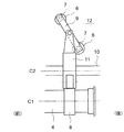
- FIG. 2 is a schematic vertical sectional view of the exhaust valve train.
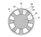
- FIG. 3 is a sectional view taken along the line III-III of FIG.
- FIG. 4 is a schematic plan view of the exhaust valve train.
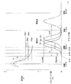
- FIG. 5 is a graph showing changes in the in-cylinder pressure and the valve lift.
- FIG. 1 schematically shows an internal combustion engine (engine) according to the present embodiment.
- the engine 1 is a diesel engine mounted on a vehicle, and the vehicle is a large vehicle such as a truck.
- the vehicle may be a small vehicle such as a passenger car, or the engine may be a gasoline engine.
- the engine is an in-line four-cylinder engine, and # 1 to # 4 cylinders are arranged in order from the front of the engine.
- the engine 1 has an exhaust passage 2 defined by an exhaust pipe or the like and through which the exhaust gas G flows.
- an oxidation catalyst (DOC) 91, a filter (DPF) 92, a NOx catalyst (SCR) 93, and an ammonia oxidation catalyst (ASC) 94 are provided in this order from the upstream side.
- Each of these constitutes a post-processing member that executes the exhaust post-processing.
- an addition valve 95 for adding urea water is provided. The number and type of the post-processing members can be changed.
- the engine 1 has an intake camshaft 3 for opening and closing an intake valve, and an exhaust camshaft 4 for opening and closing an exhaust valve.
- An intake valve and an exhaust valve are collectively called an engine valve.
- the engine 1 has a variable mechanism 5 for changing the valve timing of the engine valve.
- variable mechanism 5 changes the valve timing of the exhaust valve, and is attached to the exhaust camshaft 4.
- Another variable mechanism for changing the valve timing of the intake valve may be provided alternatively or additionally.
- the engine 1 has an injector (not shown) for injecting fuel into a combustion chamber in a cylinder, and an in-cylinder pressure sensor 96 for detecting an in-cylinder pressure in the cylinder for each cylinder.
- FIGS. 2 and 4 For convenience, one end (the left side in FIGS. 2 and 4) in the direction (axial direction) of the central axis C1 of the exhaust camshaft 4 will be referred to as a front, and the other end (the right side in FIGS. 2 and 4) as a rear. These front and rear directions coincide with the front and rear directions of the engine and the vehicle (the engine is placed vertically). However, they do not necessarily have to match.
- the # 1 to # 4 cylinders are arranged in order from the front, and FIGS. 2 and 4 show the configuration around the rearmost # 4 cylinder.
- a cam 8 for opening the exhaust valve 7 against the urging force of the valve spring 6 is fixedly provided on the exhaust camshaft 4.
- Two exhaust valves 7 are provided for each cylinder, and a valve bridge 9 is bridged between these two exhaust valves 7.
- the cam 8 is configured to simultaneously open and close the two exhaust valves 7 via a rocker arm 11 rotatably supported by a rocker shaft 10 and a valve bridge 9.
- C2 indicates the central axis of the rocker shaft 10.
- the exhaust camshaft 4 is supported between the lower cam carrier 12 and the upper cylinder head 13 so as to be rotatable in the radial direction.
- the exhaust camshaft 4 is provided with flanges 14 and 15 for positioning the exhaust camshaft 4 in the thrust direction with the cam carrier 12 and the cylinder head 13 interposed therebetween in the axial direction.
- the rear end of the exhaust camshaft 4 located behind the cam carrier 12 and the cylinder head 13 is rotatably accommodated in the housing 30 of the variable mechanism 5.
- a final gear 16 of a power transmission mechanism for transmitting power from the crankshaft is meshed with an input gear 17 provided on the housing 30.
- the exhaust camshaft 4 receives a rotational driving force from a crankshaft through the input gear 17.
- the variable mechanism 5 is configured to continuously and continuously change the valve timing of the exhaust valve 7 between the most advanced position S1 and the most retarded position S2 as shown in FIG.
- the valve timing includes both an opening timing at which the exhaust valve 7 starts opening and a closing timing at which the exhaust valve 7 ends opening.
- a crank angle period during which the exhaust valve 7 is open (that is, the valve lift amount VL is larger than zero) is referred to as a working angle.
- the opening timing and the closing timing are continuously changed by the variable width X.
- variable mechanism 5 has a rotor 31 formed at the rear end of the exhaust camshaft 4 and the above-described housing 30 that houses the rotor 31 so as to be relatively rotatable.
- a plurality of (four) housing vanes 32 projecting inward in the radial direction are formed at equal intervals in the circumferential direction in the housing 30, and a hydraulic chamber 33 is formed between the housing vanes 32.
- a plurality (four) of rotor vanes 34 projecting outward in the radial direction are formed on the rotor 31 at equal intervals in the circumferential direction, and these rotor vanes 34 partition each hydraulic chamber 33 before and after in the camshaft rotation direction R.
- the advanced chamber 35 is located rearward in the rotational direction
- the retard chamber 36 is located forward in the rotational direction.
- an advanced oil passage 37 communicating with the advance chamber 35 and a retard oil passage 38 communicated with the retard chamber 36 are formed inside the exhaust camshaft 4.
- An advancing oil supply hole 39 for connecting the advancing oil passage 37 to the oil gallery 41 is formed inside the cylinder head 13.
- a retarding oil supply hole 40 for communicating the retarding oil passage 38 with the oil gallery 41 is formed.
- the oil gallery 41 is a space formed inside the cylinder block as an oil reservoir for storing high-pressure oil (pressure oil as a pressure fluid).
- the advance chamber 35, the advance oil passage 37, and the advance oil supply hole 39 constitute an advance flow path. Further, the retard chamber 36, the retard oil passage 38, and the retard oil supply hole 40 constitute a retard passage.
- a hydraulic circuit is configured to control the hydraulic pressure supplied to the advance channel and the retard channel, and thus to control the hydraulic pressure supplied to the variable mechanism 5.
- the hydraulic circuit includes an oil gallery 41 as a hydraulic pressure source, an oil pan 43 as an oil tank for storing oil at normal pressure, an oil gallery 41, an oil pan 43, an advance oil supply hole 39, and a retard oil.
- the OCV 42 is constituted by a solenoid valve.
- An oil pump (not shown) sucks oil from the oil pan 43 and discharges the oil toward the oil gallery 41.
- an oil pump may be used directly as a hydraulic pressure source.
- an electronic control unit (referred to as ECU) 100 as a control unit, circuit element or controller is provided.
- the ECU 100 controls the entire engine, and includes a CPU, a ROM, a RAM, input / output ports, a storage device, and the like.
- the ECU 100 is configured to control the OCV 42 and control the valve timing of the variable mechanism 5 and thus the exhaust valve 7.
- the ECU 100 is also configured to control the addition valve 95.
- the variable mechanism 5 is controlled as follows.
- the OCV 42 is switched to the advanced position by the ECU 100, and the high-pressure oil stored in the oil gallery 41 passes through the advanced oil supply hole 39 and the advanced oil passage 37 to the advanced chamber 35 in this order. be introduced.
- the high-pressure oil in the retard chamber 36 is discharged to the oil pan 43 via the retard oil passage 38 and the retard oil supply hole 40 in this order.
- the oil pressure in the advance chamber 35 becomes higher than the oil pressure in the retard chamber 36, and the rotor 31 and thus the exhaust camshaft 4 are advanced.
- the OCV 42 is switched to the retard position by the ECU 100, and the high-pressure oil in the advance chamber 35 passes through the advance oil passage 37 and the advance oil supply hole 39 to the oil pan 43 in this order. Is discharged.
- the high-pressure oil stored in the oil gallery 41 is introduced into the retard chamber 36 through the retard oil supply hole 40 and the retard oil passage 38 in this order. Then, the oil pressure in the retard chamber 36 becomes higher than the oil pressure in the advance chamber 35, and the rotor 31 and thus the exhaust camshaft 4 are retarded with respect to the housing 30.
- the OCV 42 is switched to the holding position by the ECU 100, and the supply and discharge of the high-pressure oil to the advance chamber 35 and the retard chamber 36 are stopped.
- the rotor 31 and the exhaust camshaft 4 are held at a relative position with respect to the housing 30 such that the oil pressure in the advance chamber 35 and the oil pressure in the retard chamber 36 become equal, and the valve timing is maintained at a constant timing. Will be retained.
- the control of the variable mechanism 5 or the valve timing is performed by the ECU 100 based on various conditions such as an operating state of the engine and a warm-up state.
- the valve timing is controlled by controlling the advance amount with reference to the most retarded position S2.
- the temperature of the exhaust gas is increased in order to promote warm-up of the post-processing members.
- Exhaust temperature rise control is performed.
- the valve timing is advanced to the most advanced position S1.
- the exhaust valve opening timing near or immediately before the exhaust BDC at the most retarded position S2 is advanced to near the middle part of the expansion stroke, and the exhaust gas whose temperature is increased by the earlier exhaust valve opening timing is increased. Is discharged into the exhaust passage 2, and the exhaust gas temperature is raised. Then, warm-up of the post-processing member is promoted.
- the in-cylinder pressure at the opening timing of the exhaust valve may rise more than expected for some reason and exceed the allowable upper limit.
- the exhaust valve since the exhaust valve is pushed down and opened against the excessively high in-cylinder pressure, an excessive load is applied to the exhaust valve, and the exhaust valve may be damaged in the worst case.
- FIG. 5 shows the in-cylinder pressure P
- the lower part shows the valve lift VL.
- a change in the in-cylinder pressure in a certain engine operating state is indicated by a line a.
- the in-cylinder pressure at the opening timing ⁇ S2 is PS2.
- the in-cylinder pressure at the open timing ⁇ S1 is PS1.
- PS1> PS2 the more the valve timing is advanced with respect to the most retarded position S2, the higher the in-cylinder pressure at the open timing.
- the in-cylinder pressure PS1 at the open timing ⁇ S1 at the most advanced position S1 will be described as an example. Normally, the in-cylinder pressure PS1 has no problem. Conversely, the opening timing ⁇ S1 of the most advanced position S1 is set so that the in-cylinder pressure PS1 at the opening timing ⁇ S1 has no problem. Is set in advance based on
- the injector fails, and the actual fuel injection amount shifts to a larger increase side than the target fuel injection amount, the in-cylinder pressure at the opening timing ⁇ S1 becomes allowable as shown by, for example, PS1 ′.
- the ECU 100 controls the variable mechanism 5 to control the opening timing so that the actual in-cylinder pressure P at the opening timing ⁇ S1 detected by the in-cylinder pressure sensor 96 does not exceed the predetermined upper limit value Plim. Is configured.
- the ECU 100 changes the opening timing until the actual in-cylinder pressure P falls below the upper limit value Plim.
- the upper limit value Plim is set as the maximum value of the in-cylinder pressure such that the mechanical load applied to the exhaust valve at the start of opening the exhaust valve is within an allowable range, and is set to, for example, about 2 (MPa). I have.
- the ECU 100 delays the opening timing until the actual in-cylinder pressure P falls below the upper limit value Plim.
- the actual in-cylinder pressure (line a) at the opening timing ⁇ S1 that was PS1 in the normal state (line a) has increased to PS1 ′ due to some cause, for example, the occurrence of an abnormality (line b).
- the opening timing is retarded to ⁇ S3, and as a result, the actual in-cylinder pressure is reduced to the upper limit value Plim.
- the ECU 100 controls the variable mechanism 5 to control the opening timing so that the actual in-cylinder pressure P at the opening timing of the exhaust valve does not exceed the upper limit value Plim. Excess load can be avoided, and breakage of the exhaust valve can be reliably suppressed.
- the opening timing may be changed or retarded so that the actual in-cylinder pressure P decreases to a predetermined value lower than the upper limit value Plim.
- variable valve train for an internal combustion engine that can avoid an excessive load on an engine valve.
Landscapes
- Engineering & Computer Science (AREA)
- Chemical & Material Sciences (AREA)
- Combustion & Propulsion (AREA)
- Mechanical Engineering (AREA)
- General Engineering & Computer Science (AREA)
- Output Control And Ontrol Of Special Type Engine (AREA)
Abstract
内燃機関の可変動弁装置は、エンジンバルブのバルブタイミングを変更する可変機構と、筒内圧を検出するための筒内圧センサと、エンジンバルブの開タイミングθS1において筒内圧センサにより検出された筒内圧Pが所定の上限値Plimを超えぬよう、可変機構を制御して開タイミングを制御するように構成された制御ユニットと、を備える。
Description
本開示は内燃機関の可変動弁装置に関する。
例えば車両用の内燃機関において、吸気弁または排気弁(これらを総称してエンジンバルブという)のバルブタイミングを変更する可変機構を備えたものが公知である。こうした内燃機関では、バルブタイミングがエンジン運転状態に応じた最適な値になるよう、可変機構が制御され、バルブタイミングが制御される。
ところで、エンジンバルブの開タイミングにおける筒内圧が、何等かの原因で予想以上に上昇し、許容される上限値を超えてしまうことがある。こうなると、過度に高い筒内圧に逆らってエンジンバルブを押し下げて開弁するため、エンジンバルブに過剰な負荷が掛かり、最悪エンジンバルブを破損させてしまう虞がある。
そこで本開示は、かかる事情に鑑みて創案され、その目的は、エンジンバルブへの過剰な負荷を回避することができる内燃機関の可変動弁装置を提供することにある。
本開示の一の態様によれば、
エンジンバルブのバルブタイミングを変更する可変機構と、
筒内圧を検出するための筒内圧センサと、
前記エンジンバルブの開タイミングにおいて前記筒内圧センサにより検出された筒内圧が所定の上限値を超えぬよう、前記可変機構を制御して前記開タイミングを制御するように構成された制御ユニットと、
を備えたことを特徴とする内燃機関の可変動弁装置が提供される。
エンジンバルブのバルブタイミングを変更する可変機構と、
筒内圧を検出するための筒内圧センサと、
前記エンジンバルブの開タイミングにおいて前記筒内圧センサにより検出された筒内圧が所定の上限値を超えぬよう、前記可変機構を制御して前記開タイミングを制御するように構成された制御ユニットと、
を備えたことを特徴とする内燃機関の可変動弁装置が提供される。
好ましくは、前記制御ユニットは、検出された前記筒内圧が前記上限値を超えたとき、前記筒内圧が前記上限値以下に低下するまで前記開タイミングを変更する。
好ましくは、前記エンジンバルブは排気弁であり、
前記制御ユニットは、検出された前記筒内圧が前記上限値を超えたとき、前記筒内圧が前記上限値以下に低下するまで前記開タイミングを遅角させる。
前記制御ユニットは、検出された前記筒内圧が前記上限値を超えたとき、前記筒内圧が前記上限値以下に低下するまで前記開タイミングを遅角させる。
本開示によれば、エンジンバルブへの過剰な負荷を回避することができる。
以下、添付図面を参照して本開示の実施形態を説明する。なお本開示は以下の実施形態に限定されない点に留意すべきである。
図1は、本実施形態に係る内燃機関(エンジン)を概略的に示す。エンジン1は車両に搭載されたディーゼルエンジンであり、車両はトラック等の大型車両である。しかしながら、車両およびエンジンの種類、形式、用途等に特に限定はなく、例えば車両は乗用車等の小型車両であってもよいし、エンジンはガソリンエンジンであってもよい。本実施形態の場合、エンジンは直列4気筒エンジンであり、エンジンの前方から順に#1気筒~#4気筒が配置される。
エンジン1は、排気管等により画成されて排気ガスGが流される排気通路2を有する。排気通路2には、上流側から順に、酸化触媒(DOC)91、フィルタ(DPF)92、NOx触媒(SCR)93およびアンモニア酸化触媒(ASC)94が設けられる。これらはそれぞれ排気後処理を実行する後処理部材をなす。SCR93の直前には尿素水を添加する添加弁95が設けられる。なお、後処理部材の数や種類は変更可能である。
エンジン1は、吸気弁を開閉するための吸気カムシャフト3と、排気弁を開閉するための排気カムシャフト4とを有する。吸気弁および排気弁を総称してエンジンバルブという。またエンジン1は、エンジンバルブのバルブタイミングを変更する可変機構5を有する。
本実施形態の可変機構5は、排気弁のバルブタイミングを変更するものであり、排気カムシャフト4に付設される。なお吸気弁のバルブタイミングを変更する別の可変機構が代替的または追加的に設けられてもよい。
またエンジン1は、シリンダ内の燃焼室に燃料を噴射するインジェクタ(図示せず)と、シリンダ内の筒内圧を検出するための筒内圧センサ96とを気筒毎に有する。
以下、図2~図4を参照して、排気カムシャフト4および可変機構5を含む排気動弁系の構成を説明する。便宜上、排気カムシャフト4の中心軸C1の方向(軸方向)における一端側(図2,図4の左側)を前、他端側(図2,図4の右側)を後とする。これら前後方向は、エンジンおよび車両の前後方向と一致する(エンジンは縦置きされる)。但し必ずしも一致しなくてもよい。前方から順に#1気筒~#4気筒が配置され、図2,図4は最後端の#4気筒周辺の構成を示す。
図4に示すように、排気カムシャフト4には、バルブスプリング6の付勢力に抗じて排気弁7を開弁するカム8が固設されている。排気弁7は1気筒当たりに二つ設けられ、これら二つの排気弁7にバルブブリッジ9が掛け渡される。カム8は、ロッカーシャフト10に回動可能に支持されたロッカーアーム11と、バルブブリッジ9とを介して、二つの排気弁7を同時に開閉するようになっている。C2はロッカーシャフト10の中心軸を示す。
図2に示すように、排気カムシャフト4は、下側のカムキャリア12と、上側のシリンダヘッド13との間に挟まれてラジアル方向に回転可能に支持される。排気カムシャフト4には、これらカムキャリア12およびシリンダヘッド13を軸方向に挟んで排気カムシャフト4をスラスト方向に位置決めするフランジ14,15が設けられる。
カムキャリア12およびシリンダヘッド13の後方に位置する排気カムシャフト4の後端部は、可変機構5のハウジング30内に回転可能に収容されている。クランクシャフトから動力を伝達する動力伝達機構の最終ギヤ16が、ハウジング30に設けられた入力ギヤ17に噛合されている。排気カムシャフト4は、この入力ギヤ17を通じて、クランクシャフトからの回転駆動力を受ける。
可変機構5は、排気弁7のバルブタイミングを、図5に示すような最進角位置S1と最遅角位置S2との間で無段階かつ連続的に変化させるように構成されている。ここでバルブタイミングには、排気弁7が開弁を開始する開タイミングと、排気弁7が開弁を終了する閉タイミングとの両方が含まれる。また排気弁7が開弁している(すなわちバルブリフト量VLがゼロより大きくなっている)クランク角期間を作用角という。本実施形態では、作用角Δθと最大バルブリフト量VLmaxとが一定とされる一方で、開タイミングと閉タイミングが可変幅Xだけ連続的に変化させられる。
図2および図3に示すように、可変機構5は、排気カムシャフト4の後端部に形成されたロータ31と、ロータ31を相対回転可能に収容する前述のハウジング30とを有する。
図3に示すように、ハウジング30には半径方向内側に突出する複数(4つ)のハウジングベーン32が周方向等間隔で形成され、これらハウジングベーン32の間に油圧室33が形成される。他方、ロータ31には半径方向外側に突出する複数(4つ)のロータベーン34が周方向等間隔で形成され、これらロータベーン34は各油圧室33を、カムシャフト回転方向Rの前後に仕切る。仕切られた油圧室33のうち、回転方向後方に位置するのは進角室35であり、回転方向前方に位置するのは遅角室36である。
図2に示すように、排気カムシャフト4の内部には、進角室35に連通された進角用オイル通路37と、遅角室36に連通された遅角用オイル通路38とが形成される。シリンダヘッド13の内部には、進角用オイル通路37をオイルギャラリ41に連通させるための進角用オイル供給穴39が形成される。カムキャリア12の内部には、遅角用オイル通路38をオイルギャラリ41に連通させるための遅角用オイル供給穴40が形成される。オイルギャラリ41は、シリンダブロックの内部に形成され高圧オイル(圧力流体としての圧油)を貯留するオイル溜めとしての空間である。
進角室35、進角用オイル通路37および進角用オイル供給穴39は進角用流路を構成する。また遅角室36、遅角用オイル通路38および遅角用オイル供給穴40は遅角用流路を構成する。これら進角用流路および遅角用流路に供給される油圧を制御し、ひいては可変機構5に供給される油圧を制御するため、油圧回路が構成される。
油圧回路は、油圧源としてのオイルギャラリ41と、オイルを常圧で貯留するオイルタンクとしてのオイルパン43と、これらオイルギャラリ41、オイルパン43、進角用オイル供給穴39および遅角用オイル供給穴40の連通状態を切り替える切替バルブ(OCVという)42とを含む。OCV42はソレノイドバルブにより構成される。
なお、図示しないオイルポンプがオイルパン43のオイルを吸引し、オイルギャラリ41に向けて吐出する。オイルギャラリ41の代わりに、オイルポンプを直接的に油圧源として用いてもよい。
他方、制御ユニット、回路要素(circuitry)もしくはコントローラとしての電子制御ユニット(ECUという)100が設けられる。ECU100はエンジン全体の制御を司るもので、CPU、ROM、RAM、入出力ポートおよび記憶装置等を含む。ECU100は、OCV42を制御し、可変機構5ひいては排気弁7のバルブタイミングを制御するように構成されている。またECU100は、添加弁95をも制御するように構成されている。
可変機構5は次のように制御される。バルブタイミングの進角時、OCV42がECU100により進角位置に切り替えられ、オイルギャラリ41に貯留された高圧オイルが進角用オイル供給穴39、進角用オイル通路37を順に経て進角室35に導入される。また遅角室36内の高圧オイルは、遅角用オイル通路38および遅角用オイル供給穴40を順に経てオイルパン43に排出される。すると、進角室35内の油圧が遅角室36内の油圧より高くなり、ロータ31ひいては排気カムシャフト4が、進角動作させられる。
他方、バルブタイミングの遅角時には、OCV42がECU100により遅角位置に切り替えられ、進角室35内の高圧オイルが進角用オイル通路37、進角用オイル供給穴39を順に経てオイルパン43に排出される。またオイルギャラリ41に貯留された高圧オイルは、遅角用オイル供給穴40、遅角用オイル通路38を順に経て遅角室36に導入される。すると、遅角室36内の油圧が進角室35内の油圧より高くなり、ロータ31ひいては排気カムシャフト4が、ハウジング30に対し遅角動作させられる。
他方、バルブタイミングの保持時には、OCV42がECU100により保持位置に切り替えられ、進角室35および遅角室36に対する高圧オイルの供給および排出は停止される。これにより、ロータ31および排気カムシャフト4は、進角室35内の油圧と遅角室36内の油圧とが等しくなるような、ハウジング30に対する相対位置に保持され、バルブタイミングは一定のタイミングに保持される。
こうした可変機構5ないしバルブタイミングの制御は、ECU100がエンジンの運転状態や暖機状態等の各種条件に基づいて行う。この際、最遅角位置S2を基準とした進角量を制御することによりバルブタイミングが制御される。例えば冷間始動後で前述の後処理部材(DOC91、DPF92、SCR93、ASC94)が未だ活性化していないようなときに、後処理部材の暖機を促進する目的で、排気ガスの温度を上昇させる排気昇温制御が行われる。このとき、バルブタイミングが最進角位置S1まで進角させられる。すると、最遅角位置S2で排気BDCの近傍もしくは直前であった排気弁開タイミングが、膨張行程の中間部付近まで進角され、排気弁開タイミングが早まった分だけ温度が高くなった排気ガスが排気通路2に排出され、排気昇温が実行される。そして後処理部材の暖機が促進される。
ところで、排気弁の開タイミングにおける筒内圧が、何等かの原因で予想以上に上昇し、許容される上限値を超えてしまうことがある。こうなると、過度に高い筒内圧に逆らって排気弁を押し下げて開弁するため、排気弁に過剰な負荷が掛かり、最悪排気弁を破損させてしまう虞がある。
これを図5を参照してより詳細に説明する。図5の上段は筒内圧P、下段はバルブリフト量VLを示す。あるエンジン運転状態における筒内圧の変化を線aで示す。この線aにおいて、バルブタイミングが最遅角位置S2のとき、開タイミングθS2における筒内圧はPS2である。バルブタイミングが最進角位置S1のとき、開タイミングθS1における筒内圧はPS1である。PS1>PS2であり、最遅角位置S2を基準としてバルブタイミングが進角されるほど、開タイミングにおける筒内圧は高くなる。なお、燃料の燃焼により筒内圧が最大となるタイミングθpmaxは圧縮上死点(TDC)の直後に現れる。エンジン運転状態が一定であれば、バルブタイミングが変化しても、最大筒内圧の大きさと筒内圧変化曲線aとは実質的に変化しない。
便宜上、最進角位置S1のときの開タイミングθS1における筒内圧PS1を例に挙げて説明する。通常、この筒内圧PS1は、問題のない大きさであり、逆に言えば、開タイミングθS1における筒内圧PS1が問題のない大きさとなるよう、最進角位置S1の開タイミングθS1が実機試験等に基づいて予め設定されている。
しかし、例えばエンジンに異常が発生し、インジェクタが故障して、実際の燃料噴射量が目標燃料噴射量より大きく増大側にずれると、開タイミングθS1における筒内圧が例えばPS1’で示すように、許容される所定の上限値Plimを超えて、大きく増大側にずれる。すると、こうした過度に高い筒内圧PS1’に逆らって排気弁を押し下げて開弁するため、排気弁に過剰な負荷が掛かり、最悪排気弁を破損させてしまう虞がある。
そこで本実施形態において、ECU100は、筒内圧センサ96により検出された開タイミングθS1における実際の筒内圧Pが所定の上限値Plimを超えぬよう、可変機構5を制御して開タイミングを制御するように構成されている。ECU100は、実際の筒内圧Pが上限値Plimを超えたとき、実際の筒内圧Pが上限値Plim以下に低下するまで開タイミングを変更する。上限値Plimは、排気弁の開弁開始時に排気弁に印加される機械的負荷が許容範囲内となるような筒内圧の最大値として設定されており、例えば約2(MPa)に設定されている。
より具体的には、ECU100は、実際の筒内圧Pが上限値Plimを超えたとき、実際の筒内圧Pが上限値Plim以下に低下するまで開タイミングを遅角させる。図5に示す例では、正常時にPS1であった開タイミングθS1の実際の筒内圧(線a)が、何等かの原因、例えば異常の発生によりPS1’まで増大したため(線b)、バルブタイミングが位置S3まで遅角されると共に、開タイミングがθS3まで遅角され、その結果、実際の筒内圧が上限値Plimまで低下されている。
このように本実施形態によれば、排気弁の開タイミングにおける実際の筒内圧Pが上限値Plimを超えぬよう、ECU100が可変機構5を制御して開タイミングを制御するので、排気弁への過剰な負荷を回避することができ、排気弁の破損をも確実に抑制することができる。
以上、本開示の実施形態を詳細に述べたが、本開示の実施形態は他にも様々考えられる。
(1)例えば、実際の筒内圧Pが上限値Plimより低い所定値まで低下するように、開タイミングを変更もしくは遅角させてもよい。
(2)上記実施形態では、最進角位置S1のときに開タイミングθS1が上限値Plimを超えた場合を説明したが、最進角位置S1以外の位置、すなわち最進角位置S1より遅角側の任意の位置のときに開タイミングが上限値Plimを超えた場合でも、本開示は適用可能である。
本開示の実施形態は前述の実施形態のみに限らず、特許請求の範囲によって規定される本開示の思想に包含されるあらゆる変形例や応用例、均等物が本開示に含まれる。従って本開示は、限定的に解釈されるべきではなく、本開示の思想の範囲内に帰属する他の任意の技術にも適用することが可能である。
本出願は、2018年09月13日付で出願された日本国特許出願(特願2018-171866)に基づくものであり、その内容はここに参照として取り込まれる。
本開示によれば、エンジンバルブへの過剰な負荷を回避することができる内燃機関の可変動弁装置を提供する点において有用である。
5 可変機構
7 排気弁
96 筒内圧センサ
100 電子制御ユニット(ECU)
7 排気弁
96 筒内圧センサ
100 電子制御ユニット(ECU)
Claims (3)
- エンジンバルブのバルブタイミングを変更する可変機構と、
筒内圧を検出するための筒内圧センサと、
前記エンジンバルブの開タイミングにおいて前記筒内圧センサにより検出された筒内圧が所定の上限値を超えぬよう、前記可変機構を制御して前記開タイミングを制御するように構成された制御ユニットと、
を備えたことを特徴とする内燃機関の可変動弁装置。 - 前記制御ユニットは、検出された前記筒内圧が前記上限値を超えたとき、前記筒内圧が前記上限値以下に低下するまで前記開タイミングを変更する
請求項1に記載の内燃機関の可変動弁装置。 - 前記エンジンバルブは排気弁であり、
前記制御ユニットは、検出された前記筒内圧が前記上限値を超えたとき、前記筒内圧が前記上限値以下に低下するまで前記開タイミングを遅角させる
請求項1に記載の内燃機関の可変動弁装置。
Applications Claiming Priority (2)
| Application Number | Priority Date | Filing Date | Title |
|---|---|---|---|
| JP2018171866A JP2020041534A (ja) | 2018-09-13 | 2018-09-13 | 内燃機関の可変動弁装置 |
| JP2018-171866 | 2018-09-13 |
Publications (1)
| Publication Number | Publication Date |
|---|---|
| WO2020054699A1 true WO2020054699A1 (ja) | 2020-03-19 |
Family
ID=69778302
Family Applications (1)
| Application Number | Title | Priority Date | Filing Date |
|---|---|---|---|
| PCT/JP2019/035495 Ceased WO2020054699A1 (ja) | 2018-09-13 | 2019-09-10 | 内燃機関の可変動弁装置 |
Country Status (2)
| Country | Link |
|---|---|
| JP (1) | JP2020041534A (ja) |
| WO (1) | WO2020054699A1 (ja) |
Citations (4)
| Publication number | Priority date | Publication date | Assignee | Title |
|---|---|---|---|---|
| JP2004052666A (ja) * | 2002-07-19 | 2004-02-19 | Nippon Soken Inc | 内燃機関用バルブタイミング制御装置 |
| JP2005147058A (ja) * | 2003-11-18 | 2005-06-09 | Toyota Motor Corp | 内燃機関の制御装置 |
| JP2005273462A (ja) * | 2004-03-23 | 2005-10-06 | Nissan Motor Co Ltd | 内燃機関の制御装置 |
| JP2018044480A (ja) * | 2016-09-14 | 2018-03-22 | 日立オートモティブシステムズ株式会社 | 可変動弁装置及び可変動弁装置のコントローラ |
-
2018
- 2018-09-13 JP JP2018171866A patent/JP2020041534A/ja active Pending
-
2019
- 2019-09-10 WO PCT/JP2019/035495 patent/WO2020054699A1/ja not_active Ceased
Patent Citations (4)
| Publication number | Priority date | Publication date | Assignee | Title |
|---|---|---|---|---|
| JP2004052666A (ja) * | 2002-07-19 | 2004-02-19 | Nippon Soken Inc | 内燃機関用バルブタイミング制御装置 |
| JP2005147058A (ja) * | 2003-11-18 | 2005-06-09 | Toyota Motor Corp | 内燃機関の制御装置 |
| JP2005273462A (ja) * | 2004-03-23 | 2005-10-06 | Nissan Motor Co Ltd | 内燃機関の制御装置 |
| JP2018044480A (ja) * | 2016-09-14 | 2018-03-22 | 日立オートモティブシステムズ株式会社 | 可変動弁装置及び可変動弁装置のコントローラ |
Also Published As
| Publication number | Publication date |
|---|---|
| JP2020041534A (ja) | 2020-03-19 |
Similar Documents
| Publication | Publication Date | Title |
|---|---|---|
| JP6279127B2 (ja) | 油圧により係合されるロックピンを備えた可変カムシャフトタイミング機構 | |
| JP6163831B2 (ja) | エンジンのオイル供給装置 | |
| CN105189977B (zh) | 用于控制多缸发动机的控制装置 | |
| CN105089732B (zh) | 内燃机的控制装置以及内燃机的可变气门装置 | |
| CN110402327B (zh) | 发动机的控制装置及控制方法 | |
| CN110382844A (zh) | 发动机的控制装置 | |
| CN110382845A (zh) | 发动机的控制装置 | |
| EP3132133B1 (en) | Engine with a variable stroke direct injection fuel pump system and method to control the engine | |
| JP5859493B2 (ja) | 内燃機関の油路構造 | |
| JP4075448B2 (ja) | 内燃機関の油圧制御装置 | |
| JP2008057349A (ja) | エンジンシステム | |
| US11156170B2 (en) | Control device for internal combustion engine | |
| JP2020041534A (ja) | 内燃機関の可変動弁装置 | |
| JP6020307B2 (ja) | 多気筒エンジンの制御装置 | |
| JPH1113502A (ja) | 内燃機関の異常筒内圧抑制装置 | |
| JP6332314B2 (ja) | エンジンのオイル供給装置 | |
| US11203954B2 (en) | Pre-lubrication and skip fire operations during engine cranking | |
| JP7472643B2 (ja) | エンジン装置 | |
| GB2394750A (en) | I.c. engine using disabled cylinders to pump secondary air to exhaust emission after-treatment device | |
| JP6245454B2 (ja) | エンジンの制御装置 | |
| JP7106933B2 (ja) | 内燃機関の動弁装置 | |
| JP2013160172A (ja) | 内燃機関の可変動弁装置 | |
| WO2020004169A1 (ja) | 内燃機関の排気昇温装置および排気昇温制御方法 | |
| WO2020189546A1 (ja) | 内燃機関の可変動弁装置 | |
| JP2019132206A (ja) | エンジンの油圧供給構造 |
Legal Events
| Date | Code | Title | Description |
|---|---|---|---|
| 121 | Ep: the epo has been informed by wipo that ep was designated in this application |
Ref document number: 19859440 Country of ref document: EP Kind code of ref document: A1 |
|
| NENP | Non-entry into the national phase |
Ref country code: DE |
|
| 122 | Ep: pct application non-entry in european phase |
Ref document number: 19859440 Country of ref document: EP Kind code of ref document: A1 |