WO2020054323A1 - 流体圧シリンダの駆動装置 - Google Patents
流体圧シリンダの駆動装置 Download PDFInfo
- Publication number
- WO2020054323A1 WO2020054323A1 PCT/JP2019/032238 JP2019032238W WO2020054323A1 WO 2020054323 A1 WO2020054323 A1 WO 2020054323A1 JP 2019032238 W JP2019032238 W JP 2019032238W WO 2020054323 A1 WO2020054323 A1 WO 2020054323A1
- Authority
- WO
- WIPO (PCT)
- Prior art keywords
- pressure
- port
- pressure chamber
- chamber
- cylinder
- Prior art date
- Legal status (The legal status is an assumption and is not a legal conclusion. Google has not performed a legal analysis and makes no representation as to the accuracy of the status listed.)
- Ceased
Links
Images



Classifications
-
- F—MECHANICAL ENGINEERING; LIGHTING; HEATING; WEAPONS; BLASTING
- F15—FLUID-PRESSURE ACTUATORS; HYDRAULICS OR PNEUMATICS IN GENERAL
- F15B—SYSTEMS ACTING BY MEANS OF FLUIDS IN GENERAL; FLUID-PRESSURE ACTUATORS, e.g. SERVOMOTORS; DETAILS OF FLUID-PRESSURE SYSTEMS, NOT OTHERWISE PROVIDED FOR
- F15B11/00—Servomotor systems without provision for follow-up action; Circuits therefor
- F15B11/02—Systems essentially incorporating special features for controlling the speed or actuating force of an output member
- F15B11/024—Systems essentially incorporating special features for controlling the speed or actuating force of an output member by means of differential connection of the servomotor lines, e.g. regenerative circuits
-
- F—MECHANICAL ENGINEERING; LIGHTING; HEATING; WEAPONS; BLASTING
- F15—FLUID-PRESSURE ACTUATORS; HYDRAULICS OR PNEUMATICS IN GENERAL
- F15B—SYSTEMS ACTING BY MEANS OF FLUIDS IN GENERAL; FLUID-PRESSURE ACTUATORS, e.g. SERVOMOTORS; DETAILS OF FLUID-PRESSURE SYSTEMS, NOT OTHERWISE PROVIDED FOR
- F15B11/00—Servomotor systems without provision for follow-up action; Circuits therefor
- F15B11/02—Systems essentially incorporating special features for controlling the speed or actuating force of an output member
- F15B11/028—Systems essentially incorporating special features for controlling the speed or actuating force of an output member for controlling the actuating force
-
- F—MECHANICAL ENGINEERING; LIGHTING; HEATING; WEAPONS; BLASTING
- F15—FLUID-PRESSURE ACTUATORS; HYDRAULICS OR PNEUMATICS IN GENERAL
- F15B—SYSTEMS ACTING BY MEANS OF FLUIDS IN GENERAL; FLUID-PRESSURE ACTUATORS, e.g. SERVOMOTORS; DETAILS OF FLUID-PRESSURE SYSTEMS, NOT OTHERWISE PROVIDED FOR
- F15B15/00—Fluid-actuated devices for displacing a member from one position to another; Gearing associated therewith
- F15B15/20—Other details, e.g. assembly with regulating devices
- F15B15/22—Other details, e.g. assembly with regulating devices for accelerating or decelerating the stroke
-
- F—MECHANICAL ENGINEERING; LIGHTING; HEATING; WEAPONS; BLASTING
- F15—FLUID-PRESSURE ACTUATORS; HYDRAULICS OR PNEUMATICS IN GENERAL
- F15B—SYSTEMS ACTING BY MEANS OF FLUIDS IN GENERAL; FLUID-PRESSURE ACTUATORS, e.g. SERVOMOTORS; DETAILS OF FLUID-PRESSURE SYSTEMS, NOT OTHERWISE PROVIDED FOR
- F15B15/00—Fluid-actuated devices for displacing a member from one position to another; Gearing associated therewith
- F15B15/20—Other details, e.g. assembly with regulating devices
- F15B15/26—Locking mechanisms
Definitions
- the present invention relates to a driving device for a hydraulic cylinder, and more particularly to a driving device for a double-acting hydraulic cylinder that does not require a large driving force in a return stroke.
- a part of exhaust gas discharged from one cylinder chamber is used for a return operation, and compressed air having a pressure lower than air pressure supplied in a cylinder driving process is used. Perform a return operation.
- auxiliary mechanism such as a cylinder with a lock device or a cylinder with a booster mechanism
- the operation of the auxiliary mechanism is reliably performed only by low-pressure exhaust supplied during the return operation. It may not be possible.
- an object of the present invention is to provide a drive device for a fluid pressure cylinder that can supply high-pressure air for operation of an auxiliary mechanism unit without complicating a circuit at the time of a cylinder return operation or the like.
- One aspect of the present invention is a drive device for a double-acting hydraulic cylinder having an auxiliary mechanism that operates during a return operation by air pressure, comprising a switching valve, a high-pressure air supply source, an exhaust port, and a check valve.
- a switching valve In the first position of the switching valve, one cylinder chamber communicates with the high-pressure air supply source, and the other cylinder chamber and the auxiliary mechanism communicate with the exhaust port.
- the one cylinder chamber communicates with the other cylinder chamber via the check valve, the one cylinder chamber communicates with the exhaust port, and the auxiliary mechanism communicates with a high-pressure air supply source.
- the hydraulic cylinder driving device of the present invention high-pressure air is supplied from the high-pressure air supply source at the second position of the switching valve. Therefore, there is no need to separately add a high-pressure air supply circuit, and the device configuration of the driving device can be simplified.
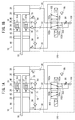
- FIG. 1A is a fluid circuit diagram showing a connection state of a switching valve at a first position in a fluid pressure cylinder and a driving device according to the first embodiment
- FIG. 1B is a hydraulic circuit diagram of the switching valve of FIG. 1A at a second position
- FIG. 4 is a fluid circuit diagram showing a connection state.
- FIG. 1B is a cross-sectional view of the hydraulic cylinder of FIG. 1A.
- 3A is a fluid circuit diagram showing a connection state of a switching valve at a first position in a hydraulic cylinder and a driving device according to a second embodiment
- FIG. 3B is a fluid circuit diagram of the switching valve of FIG. 3A at a second position.
- FIG. 4 is a fluid circuit diagram showing a connection state.
- FIG. 4 is a fluid circuit diagram showing a connection state.
- FIG. 9 is a fluid circuit diagram of a hydraulic cylinder with a lock device and a drive device thereof according to a third embodiment, and is a fluid circuit diagram showing a connection state of a switching valve at a first position. It is sectional drawing of the hydraulic cylinder with a lock device of FIG.
- the driving device 120 of the fluid pressure cylinder 10 of the present embodiment includes a check valve 86, a throttle valve 88, a switching valve 102, a high-pressure air supply source 104, and an exhaust port 106. ing.
- the driving device 120 is configured to supply high-pressure air to the first pressure chamber 38 of the hydraulic cylinder 10 during an operation stroke.
- the driving device 120 supplies a part of the air accumulated in the first pressure chamber 38 toward the fourth pressure chamber 44 and supplies the air to the second pressure chamber 40 in the return stroke. It is configured to supply high-pressure air.
- the switching valve 102 is, for example, a five-port two-position valve, has first to fifth ports 102a to 102e, and switches between a first position (see FIG. 1A) and a second position (see FIG. 1B). It is possible. As shown in FIGS. 1A and 1B, the first port 102a is connected to the head-side port 28 of the hydraulic cylinder 10 by a pipe. The second port 102b is connected to the adjustment port 32 by a pipe. The third port 102c is connected to the exhaust port 106 by a pipe. The fourth port 102d is connected to a high-pressure air supply source 104 by a pipe. The fifth port 102e is connected by a pipe to the exhaust port 106 via a throttle valve 88 and to the end port 30 of the fluid pressure cylinder 10 via a check valve 86.
- the switching valve 102 when the switching valve 102 is at the first position, the first port 102a and the fourth port 102d are connected, and the second port 102b and the third port 102c are connected.
- the switching valve 102 when the switching valve 102 is at the second position, the first port 102a and the fifth port 102e are connected, and the second port 102b and the fourth port 102d are connected, as shown in FIG. 1B.
- the switching valve 102 is switched between a first position and a second position by a pilot pressure from a high-pressure air supply source 104 or an electromagnetic valve.
- the check valve 86 allows the air flow from the head-side port 28 to the end-side port 30 and allows the air flow from the end-side port 30 to the head-side port 28. Block.
- the throttle valve 88 is provided to limit the amount of air in the first pressure chamber 38 exhausted from the exhaust port 106, and is a variable throttle valve capable of changing a passage area so that the exhaust flow rate can be adjusted. Is configured as
- an air tank may be provided in the piping connecting the check valve 86 and the end-side port 30 to accumulate the air supplied from the head-side port 28 to the end-side port 30 during the return stroke.
- the capacity of the air tank may be set to, for example, about half of the maximum capacity of the first pressure chamber 38. If the capacity of the pipe can be sufficiently secured, the air tank is not required.
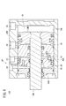
- FIG. 2 is a cross-sectional view of the hydraulic cylinder 10 driven by the driving device 120.
- the hydraulic cylinder 10 includes a cylinder body 12 that is formed of a metal material such as an aluminum alloy and extends in the axial direction.
- the cylinder body 12 includes a head-side main body portion 14 provided on the head side, an end-side main body portion 16 provided on the end side, and a partition wall provided between the head-side main body portion 14 and the end-side main body portion 16. 26.
- a circular working cylinder chamber 14b is formed inside the head-side main body portion 14, and a circular booster cylinder chamber 16b is formed inside the end-side main body portion 16.
- the working cylinder chamber 14b and the booster cylinder chamber 16b are formed to have the same inner diameter, and constitute a sliding hole 12a of the cylinder body 12.
- the working cylinder chamber 14b and the booster cylinder chamber 16b are separated by a partition wall 26.
- a working piston 20 is provided in the working cylinder chamber 14b, and a booster piston 22 is provided in the booster cylinder chamber 16b.
- the working piston 20 and the booster piston 22 are connected to the piston rod 18 that extends through the partition wall 26 and the cylinder body 12 to the end side.
- the head-side main body 14 is provided with a head-side port 28, a head cover 14c, and a working piston 20.
- the head cover 14c is mounted on the end of the working cylinder chamber 14b on the head side, and the head cover 14c seals the head side of the working cylinder chamber 14b.
- a head-side port 28 is formed near the head cover 14c.
- the head-side port 28 is formed through the head-side main body 14.
- the head-side port 28 is provided near the head-side end of the working cylinder chamber 14b and communicates with the working cylinder chamber 14b (first pressure chamber 38) through an opening 28a.
- the working piston 20 is housed in the working cylinder chamber 14b so as to be slidable in the axial direction.
- the working piston 20 hermetically partitions the working cylinder chamber 14b into a first pressure chamber 38 and a second pressure chamber 40.
- the first pressure chamber 38 is an empty chamber formed between the working piston 20 and the head cover 14c, and is formed closer to the head than the working piston 20.
- the second pressure chamber 40 is an empty chamber formed between the working piston 20 and the partition 26, and is formed on the end side of the working piston 20.
- the first pressure chamber 38 communicates with the head-side port 28.
- the working piston 20 is connected to the piston rod 18, and is configured to be displaced integrally with the piston rod 18.
- the end-side main body 16 is provided with the booster piston 22, the rod cover 48, the end-side port 30, and the auxiliary flow path 76.
- the booster piston 22 is slidably disposed in the booster cylinder chamber 16b of the end-side main body 16 in the axial direction.
- the booster piston 22 airtightly partitions the booster cylinder chamber 16b into a third pressure chamber 42 and a fourth pressure chamber 44.
- the third pressure chamber 42 is an empty chamber on the head side of the booster piston 22 and is formed between the booster piston 22 and the partition 26.
- the fourth pressure chamber 44 is an empty chamber on the end side of the booster piston 22 and is formed between the booster piston 22 and the rod cover 48.
- the fourth pressure chamber 44 communicates with the end-side port 30.
- the booster piston 22 is connected to the piston rod 18 and is configured to displace integrally with the piston rod 18 in the axial direction.
- the rod cover 48 is mounted on the end side of the booster cylinder chamber 16b, and hermetically seals the end of the booster cylinder chamber 16b on the end side. Near the radial center of the rod cover 48, an insertion hole 48a for inserting the piston rod 18 is formed extending in the axial direction.
- the end-side port 30 is formed near the end of the end-side main body 16 on the end side.
- the end-side port 30 is formed to penetrate from the outer periphery of the end-side main body 16 toward the booster cylinder chamber 16b, and communicates with the fourth pressure chamber 44 at the end-side end of the booster cylinder chamber 16b. I have.
- the auxiliary flow path 76 is a flow path formed inside the end-side main body 16 and extends in the axial direction.
- the auxiliary flow passage 76 has one end communicating with the end-side port 30 and the other end communicating with the adjustment port 32 of the partition 26.
- the third check valve 56 is provided in the middle of the auxiliary flow path 76.
- the third check valve 56 allows air flowing from the end port 30 toward the adjustment port 32 to pass therethrough and blocks air flowing in the opposite direction.
- the partition wall 26 includes a communication path 34, a conduction switching valve 35 provided in the communication path 34, an exhaust path 36, and an exhaust switching valve 37 provided in the exhaust path 36, which constitute a booster switching mechanism 33. .
- the communication passage 34 is a flow passage through which air flows between the second pressure chamber 40 and the third pressure chamber 42, and the internal flow of the conduction switching pin 35 a inserted in a through-hole penetrating the partition 26 in the axial direction. Provide a road. Opening and closing of the communication passage 34 is performed by axial displacement of the conduction switching pin 35a.
- the conduction switching valve 35 is provided with a conduction switching pin 35a.
- the conduction switching pin 35a has a closing portion on the head side for closing the through hole. When the conduction switching pin 35a moves to the end side, the closing portion closes the through hole and seals the communication path 34.
- An urging member 35f is attached to the through hole, and the urging member 35f urges the conduction switching pin 35a so as to protrude toward the head.
- the conduction switching pin 35a is configured not to hinder conduction of the communication passage 34 unless pushed out to the end side by the operating piston 20.
- the exhaust path 36 is constituted by a detection pin receiving hole 67 provided in the partition wall 26 and a connection flow path 71 communicating with the detection pin receiving hole 67 and the adjustment port 32.
- the detection pin 37a is inserted into the detection pin receiving hole 67.
- the opening and closing of the exhaust path 36 is performed by the axial displacement of the detection pin 37 a of the exhaust switching valve 37.
- the first check valve 52 provided in the connection flow passage 71 allows the passage of air flowing from the second pressure chamber 40 toward the adjustment port 32, and prevents the passage of air in the opposite direction.
- the detection pin 37a of the exhaust switching valve 37 is urged by an urging member 37f made of a spring or the like so that the tip end protrudes toward the head.
- a packing is arranged at an outer circumferential portion of the detection pin 37a at an interval in the axial direction, and is configured to prevent communication of the exhaust path 36 when the detection pin 37a is not pressed by the operating piston 20.
- the head-side main body 14 near the adjustment port 32 is provided with a replenishment flow path 78 and a second check valve 54.
- the refill channel 78 communicates with the adjustment port 32 and the second pressure chamber 40.
- the replenishment flow path 78 is provided with a second check valve 54.
- One end of the second check valve 54 communicates with the adjustment port 32 via the refill channel 78.
- the other end of the second check valve 54 communicates with the second pressure chamber 40 via the refill channel 78.
- the second check valve 54 allows the passage of air only in the direction from the adjustment port 32 to the second pressure chamber 40, and blocks the passage of air in the opposite direction. That is, the second check valve 54 is configured to allow the flow of the air supplied to the second pressure chamber 40 and block the air in the opposite direction.
- the fluid pressure cylinder 10 and the driving device 120 are configured as described above, and the operation and operation will be described below.
- the fluid pressure cylinder 10 is used in a state where high-pressure air is stored in the second pressure chamber 40 and the third pressure chamber 42. As shown in FIG. 1A, the operation stroke is performed with the switching valve 102 of the driving device 120 as the first position.
- the high-pressure air from the high-pressure air supply source 104 is supplied to the head-side port 28 via the first port 102a of the switching valve 102.
- the check valve 86 is connected to the fifth port 102e side, and high-pressure air does not flow to the check valve 86 side.
- the fourth pressure chamber 44 is connected to the exhaust port 106 via the third check valve 56, the adjustment port 32, and the second port 102b.
- the high-pressure air from the high-pressure air supply source 104 flows into the first pressure chamber 38.
- the force acting on the working piston 20 by the high-pressure air in the second pressure chamber 40 and the force acting on the booster piston 22 by the high-pressure air filled in the third pressure chamber 42 have the same magnitude and opposite directions. Does not contribute. Accordingly, a thrust corresponding to the pressure difference between the first pressure chamber 38 adjacent to the working piston 20 and the fourth pressure chamber 44 adjacent to the booster piston 22 is generated in the piston rod 18, and the piston rod 18 is moved toward the end. Stroke toward.
- high-pressure air is supplied from the high-pressure air supply source 104 to the hydraulic cylinder 10 in an amount equal to the volume of the first pressure chamber 38.
- the high-pressure air in the second pressure chamber 40 moves to the third pressure chamber 42 through the communication passage 34.
- the pressure of the high-pressure air stored in the second pressure chamber 40 and the third pressure chamber 42 is kept constant.
- the air in the fourth pressure chamber 44 is exhausted from the fourth pressure chamber 44 with the stroke of the booster piston 22.
- the air in the fourth pressure chamber 44 passes through the third check valve 56 and the auxiliary flow path 76, passes through the adjustment port 32, and as shown in FIG. 1A, through the second port 102b of the switching valve 102, through the exhaust port 106. It is exhausted from.
- the internal pressure of the second pressure chamber 40 decreases, and a thrust corresponding to the difference between the internal pressures of the second pressure chamber 40 and the first pressure chamber 38 is generated in the working piston 20. Further, in the booster piston 22, a thrust corresponding to a pressure difference between the high-pressure air stored in the third pressure chamber 42 and the pressure in the fourth pressure chamber 44 is generated. Thereby, the hydraulic cylinder 10 can increase the thrust near the stroke end.
- the return stroke of the fluid pressure cylinder 10 is performed with the switching valve 102 of the driving device 120 as the second position.
- the high-pressure air from the high-pressure air supply source 104 is supplied to the adjustment port 32 via the second port 102b of the switching valve 102.
- the first port 102a of the switching valve 102 is connected to the fifth port 102e, and the head port 28 is connected to the end port 30 via the check valve 86.
- the head-side port 28 is connected to an exhaust port 106 via a throttle valve 88.
- high-pressure air is supplied from the high-pressure air supply source 104 to the adjustment port 32 of the hydraulic cylinder 10 as shown by an arrow B.
- the high-pressure air supplied to the adjustment port 32 flows into the second pressure chamber 40 via the refill channel 78 and the second check valve 54.
- the volume of the high-pressure air supplied to the second pressure chamber 40 is equal to the amount of the high-pressure air exhausted from the second pressure chamber 40 in the boosting step. That is, the high-pressure air required for the boosting step is supplemented in the return step.
- high pressure air for exerting a boost can be supplied to the second pressure chamber 40 and the third pressure chamber 42 in the return stroke.
- the drive device 120 of the hydraulic cylinder 10 according to the present embodiment has the following effects.
- the auxiliary mechanism is constituted by the booster switching mechanism 33 for increasing the thrust near the end of the working stroke.
- the drive device 120 communicates the high pressure air supply source 104 with the second pressure chamber 40 and the third pressure chamber 42 constituting a part of the auxiliary mechanism during the return stroke of the fluid pressure cylinder 10.
- High-pressure air required for the operation of the auxiliary mechanism can be supplied.
- the return stroke of the piston rod 18 is such that exhaust air from one cylinder chamber (first pressure chamber 38) into which high-pressure air has been introduced during the operation stroke is sent to the other cylinder chamber (fourth pressure chamber 44). Perform by guiding. That is, since the operation stroke is performed by reusing the exhaust air, the supply of the high-pressure air is not required in the operation stroke, and the consumption of high-pressure air (energy consumption) can be reduced.
- a throttle valve 88 is provided between one of the cylinder chambers (the first pressure chamber 38) and the exhaust port 106 and downstream of the check valve 86.
- the throttle valve 88 By the throttle valve 88, the amount of exhaust air supplied to the other cylinder chamber (the fourth pressure chamber 44) can be adjusted, and the amount of exhaust air required for the return stroke can be optimized.
- an exhaust check valve (third check valve 56) is provided between the other cylinder chamber (the fourth pressure chamber 44) and the second port 102b of the switching valve 102.
- a driving device 120A As shown in FIG. 3A, a driving device 120A according to the present embodiment is used for driving a hydraulic cylinder 10A.
- the drive device 120A is configured to supply a small amount of high-pressure air to the lock mechanism 35A as an auxiliary mechanism in order to ensure the return operation of the hydraulic cylinder 10A.
- the drive device 120A includes a check valve 86, a throttle valve 88, a switching valve 102, a high-pressure air supply source 104, an exhaust port 106, and an exhaust check valve 112.
- the driving device 120A is configured to supply high-pressure air to the first pressure chamber 38 of the operation cylinder chamber 14b in an operation step. Further, as shown in FIG. 3B, the drive device 120A supplies a part of the high-pressure air accumulated in the first pressure chamber 38 toward the second pressure chamber 40 and returns the fourth pressure chamber It is configured to supply high-pressure air from a high-pressure air supply source 104 to 44.
- the switching valve 102 is, for example, a five-port two-position valve, has first to fifth ports 102a to 102e, and switches between a first position (see FIG. 3A) and a second position (see FIG. 3B). It is possible. As shown in FIGS. 3A and 3B, the first port 102a is connected to the first pressure chamber 38 by a pipe. The second port 102b is connected to a downstream side of the fourth pressure chamber 44 and the exhaust check valve 112 by a pipe. The third port 102c is connected to the exhaust port 106 by a pipe. The fourth port 102d is connected to a high-pressure air supply source 104 by a pipe. The fifth port 102e is connected to the exhaust port 106 via a throttle valve 88 via a pipe, and to the second pressure chamber 40 via a check valve 86.
- the switching valve 102 when the switching valve 102 is at the second position, the first port 102a and the fifth port 102e are connected, and the second port 102b and the fourth port 102d are connected, as shown in FIG. 3B.
- the switching valve 102 is switched between a first position and a second position by a pilot pressure from a high-pressure air supply source 104 or an electromagnetic valve.
- the check valve 86 allows the flow of air from the first pressure chamber 38 to the second pressure chamber 40, and goes from the second pressure chamber 40 to the first pressure chamber 38. Block air flow.
- An air tank is provided in the middle of the pipe connecting the check valve 86 and the second pressure chamber 40 so that the air supplied from the first pressure chamber 38 to the second pressure chamber 40 is accumulated in the return step. Is also good.
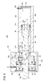
- the hydraulic cylinder 10A driven by the driving device 120A includes a cylinder body 12A that extends in the axial direction as shown in FIG.
- the cylinder body 12A includes a head-side main body portion 14A provided on the head side and an end-side main body portion 16A provided on the end side.
- a working cylinder chamber 14b having a circular cross section is formed inside the head side main body portion 14A, and a boost cylinder chamber 16b having a circular cross section is formed inside the end side main body portion 16A.
- a head-side port 28A is formed near the head-side end of the head-side main body 14A, and an operating unit exhaust port 29 is formed near an end-side end of the head-side main body 14A.
- an intensifying section exhaust port 30A is provided near the end on the end side of the end side main body 16A.
- the hydraulic cylinder 10A supplies high-pressure air (working fluid) from the head-side port 28A and exhausts internal air from the operating section exhaust port 29 and the intensifying section exhaust port 30A in the operation process, thereby the piston rod 18A. Are projected. At that time, the head-side main body portion 14A generates a large stroke motion, and the end-side main body portion 16A is configured to generate an additional thrust in the latter half of the stroke.
- the high-pressure air refers to air having a pressure higher than the pressure (for example, the atmospheric pressure) of the atmosphere in which the fluid pressure cylinder 10A is installed.
- the head-side main body 14A of the cylinder body 12A includes the working cylinder chamber 14b, the head-side port 28A, the head cover 14c, the communication passage 34A, the working-port exhaust port 29, and the piston unit 21.
- the working cylinder chamber 14b is a hollow portion having a circular cross section formed inside the side wall 14a, and extends in the axial direction.
- the head cover 14c seals the head side of the working cylinder chamber 14b.
- a head-side port 28A is formed near the head cover 14c, and communicates with the working cylinder chamber 14b.
- the head-side port 28A communicates with the first pressure chamber 38 on the head side of the working piston 20A.
- the communication passage 34A communicates with the working cylinder chamber 14b at the opening 34a.
- the opening 34a is arranged at a position separated by a predetermined distance from the end side end of the working cylinder chamber 14b.
- the opening 34a communicates with the first pressure chamber 38 on the head side of the working piston 20A when the working piston 20A moves to the end side.
- the operating section exhaust port 29 is provided on the top, side, or bottom surface of the head-side main body 14A, and penetrates the side wall 14a to communicate with the operating cylinder chamber 14b.
- the operating unit exhaust port 29 is provided on the side surface of the head-side main body 14A.
- the operating part exhaust port 29 communicates with the second pressure chamber 40 on the end side of the operating piston 20A.
- a piston unit 21 including a working piston 20A and a piston rod 18A connected to the working piston 20A is disposed inside the working cylinder chamber 14b.
- the piston unit 21 is accommodated in the working cylinder chamber 14b so as to be slidable in the axial direction.
- the piston 20A has a piston body 50 and a cylindrical sealing portion 58 extending from the piston body 50 to the end side.
- the piston body 50 hermetically partitions the inside of the working cylinder chamber 14b into a first pressure chamber 38 on the head side and a second pressure chamber 40 on the end side.
- the sealing portion 58 has an outer diameter substantially the same as the inner diameter of the communication portion 16d, which will be described later, and is formed to be freely inserted into and removed from the communication portion 16d. When the sealing portion 58 is inserted into the communication portion 16d, it seals the communication portion 16d.
- the piston rod 18A is connected to the working piston 20A.
- the piston rod 18A extends to the end side through the end-side main body 16A and the booster piston 22A.
- a connection groove 18a for connecting to the booster piston 22A is formed on the outer peripheral portion of the piston rod 18A.
- the connecting groove 18a is formed at a position separated from the connecting portion of the piston rod 18A with the working piston 20A by a predetermined distance toward the end side, and is formed annularly over the entire circumference of the piston rod 18A in the circumferential direction. .
- the end-side main body 16A includes a booster cylinder chamber 16b, a communication portion 16d, a booster piston 22A, a booster exhaust port 30A, a lock mechanism 35A, and a position holding unit 66.
- the booster cylinder chamber 16b is a hollow section having a circular cross section, and is formed to penetrate the end-side main body 16A in the axial direction. The end on the end side of the booster cylinder chamber 16b is sealed by a rod cover 48A.
- the boost cylinder chamber 16b has a connecting portion 16d on the head side.
- the connecting portion 16d is formed to have a larger inner diameter than the piston rod 18A, and is configured to form a space in which air can move between the connecting portion 16d and the piston rod 18A.
- a circular ring-shaped packing 16j is mounted on the inner peripheral surface of the connecting portion 16d.
- the packing 16j hermetically seals the working cylinder chamber 14b and the booster cylinder chamber 16b by being in close contact with the outer peripheral surface of the sealing portion 58 of the working piston 20A.
- the rod cover 48A is formed in a substantially cylindrical shape, and a rod hole for inserting the piston rod 18A is formed near the center in the radial direction so as to extend in the axial direction.
- the booster piston 22A hermetically partitions the end-side main body 16A into a third pressure chamber 42 on the head side and a fourth pressure chamber 44 on the end side. Further, the piston main body 60 is provided with a lock mechanism 35A for connecting the booster piston 22A to the piston rod 18A.
- the lock mechanism 35A has a through hole 63 penetrating in the radial direction, and a lock piston 36A is inserted into the through hole 63.
- the outer peripheral side of the through hole 63 communicates with the third pressure chamber 42.
- the lower side of the lock piston 36 ⁇ / b> A communicates with the fourth pressure chamber 44 via the ventilation path 61.
- the lock piston 36A is configured to protrude toward the piston rod 18A and engage with the connection groove 18a of the piston rod 18A when high-pressure air flows into the third pressure chamber 42.
- the communication passage 34A penetrates the end-side main body 16A in the axial direction, and communicates the third pressure chamber 42 and the working cylinder chamber 14b.
- the position holding means 66 is disposed on the end side of the booster piston 22A and urges the booster piston 22A toward the head.
- the fluid pressure cylinder 10A and the driving device 120A are configured as described above, and the operation and operation will be described below.
- the operating stroke of the hydraulic cylinder 10A is performed with the switching valve 102 of the driving device 120A as the first position.
- the high-pressure air from the high-pressure air supply source 104 is supplied to the head-side port 28A via the first port 102a of the switching valve 102.
- the operating section exhaust port 29 and the booster section exhaust port 30A are connected to the second port 102b of the switching valve 102, and are connected to the exhaust port 106.
- the high-pressure air supplied to the head-side port 28A flows into the first pressure chamber 38.
- the second pressure chamber 40 adjacent to the working piston 20A communicates with the exhaust port 106 through the working unit exhaust port 29 and piping.
- a driving force corresponding to the pressure difference between the pressure in the first pressure chamber 38 and the pressure (atmospheric pressure) in the second pressure chamber 40 acts on the working piston 20A, and the working piston 20A is pushed toward the stroke end.
- the piston rod 18A is displaced integrally with the working piston 20A and moves toward the stroke end.
- the air in the second pressure chamber 40 is exhausted from the exhaust port 106.
- the third pressure chamber 42 adjacent to the booster piston 22A communicates with the exhaust port 106 (see FIG. 3A) via the second pressure chamber 40, and the fourth pressure chamber 44 communicates with the exhaust port 106 via a pipe. Therefore, no thrust is generated in the booster piston 22A, and the booster piston 22A is held at the head-side end of the booster cylinder chamber 16b by the position holding means 66.
- the sealing portion 58 is inserted into the communication portion 16d, the communication portion 16d is sealed, and the operating piston 20A moves to the end side of the opening 34a of the communication passage 34A.
- the second pressure chamber 40 and the third pressure chamber 42 are airtightly partitioned, and the first pressure chamber 38 and the third pressure chamber 42 communicate with each other via the communication passage 34A.
- the internal pressure of the third pressure chamber 42 increases, the lock piston 36A of the lock mechanism 35A engages with the connection groove 18a of the piston rod 18A, and the booster piston 22A is connected to the piston rod 18A. Further, the high-pressure air flowing into the third pressure chamber 42 generates a thrust toward the end side on the booster piston 22A. As shown in FIG. 4, since the diameter of the booster piston 22A is larger than the diameter of the working piston 20A, the booster piston 22A generates a larger thrust than the working piston 20A. Since the thrust of the boost piston 22A is added to the thrust of the working piston 20A, the thrust of the piston rod 18A increases in the latter half of the stroke.
- the piston rod 18 performs a stroke with the increased thrust until the working piston 20A and the booster piston 22A reach the stroke end. Thereafter, a return stroke is performed.
- the return stroke of the hydraulic cylinder 10A is performed with the switching valve 102 of the driving device 120A as the second position.
- the high-pressure air from the high-pressure air supply source 104 is supplied to the fourth pressure chamber 44 via the second port 102b of the switching valve 102. Note that high-pressure air from the high-pressure air supply source 104 is not supplied to the second pressure chamber 40 because it is blocked by the exhaust check valve 112.
- the first pressure chamber 38 is connected to the throttle valve 88 via the first port 102 a and the fifth port 102 e of the switching valve 102, and the high-pressure air in the first pressure chamber 38 passes through the exhaust port 106 via the throttle valve 88. It is exhausted from. A part of the high-pressure air in the first pressure chamber 38 is supplied to the second pressure chamber 40 via the check valve 86.
- the working piston 20A moves in the return direction under the action of the air pressure flowing into the second pressure chamber 40. Further, the booster piston 22A moves to the head side by the internal pressure of the fourth pressure chamber 44 and the urging force of the position holding means 66. Through the above operation, the booster piston 22A and the working piston 20A return to the starting position of the stroke, and the return process is completed.
- the driving device 120A in the return stroke, it is possible to drive the hydraulic cylinder 10A having the boosting mechanism that increases the thrust at the stroke end as the auxiliary mechanism in the return stroke. Then, high-pressure air is supplied to the lock mechanism 35A that forms a part of the booster mechanism, and the lock mechanism 35A can be reliably operated. On the other hand, since the exhaust air from one cylinder chamber (first pressure chamber 38) can be supplied to the other cylinder chamber (second pressure chamber 40), the supply of high-pressure air for performing a return stroke is unnecessary. Becomes Therefore, according to the driving device 120A, the consumption of high-pressure air (energy) can be reduced.
- a drive device 120B As shown in FIG. 5, a drive device 120B according to the present embodiment is used for driving a hydraulic cylinder 10B with a lock device.
- the drive device 120B is configured to supply a small amount of high-pressure air to a lock device 80 as an auxiliary mechanism in order to reliably lock the piston rod 18B of the hydraulic cylinder 10B.
- the drive device 120B includes a check valve 86, a throttle valve 88, a switching valve 102, a high-pressure air supply source 104, an exhaust port 106, and an exhaust check valve 112.
- the driving device 120B is configured to supply high-pressure air to the first pressure chamber 38 of the operation cylinder chamber 14b during the operation stroke. In the return stroke, the drive device 120B supplies a part of the high-pressure air accumulated in the first pressure chamber 38 toward the second pressure chamber 40, and supplies the lock device 80 with the high-pressure air from the high-pressure air supply source 104. It is configured to supply air.
- the switching valve 102 is, for example, a five-port two-position valve having first to fifth ports 102a to 102e, and is capable of switching between a first position (see FIG. 5) and a second position (not shown). It has become.
- the first port 102a is connected to the first pressure chamber 38 by a pipe.
- the second port 102b is connected by a pipe to the release port 82 of the lock device 80 and the downstream side of the exhaust check valve 112.
- the third port 102c is connected to the exhaust port 106 by a pipe.
- the fourth port 102d is connected to a high-pressure air supply source 104 by a pipe.
- the fifth port 102e is connected to the exhaust port 106 via a throttle valve 88 via a pipe, and to the second pressure chamber 40 via a check valve 86.
- the switching valve 102 when the switching valve 102 is at the first position, the first port 102a is connected to the fourth port 102d, and the second port 102b is connected to the third port 102c.
- the switching valve 102 When the switching valve 102 is at the second position, the first port 102a and the fifth port 102e are connected, and the second port 102b and the fourth port 102d are connected.
- the switching valve 102 is switched between a first position and a second position by a pilot pressure from a high-pressure air supply source 104 or an electromagnetic valve.
- the check valve 86 allows the flow of air from the first pressure chamber 38 to the second pressure chamber 40, and goes from the second pressure chamber 40 to the first pressure chamber 38. Block air flow.
- the other lock port 84 of the lock device 80 is open to the atmosphere. Further, an air tank is provided in the middle of the pipe connecting the check valve 86 and the second pressure chamber 40 so that the air supplied from the first pressure chamber 38 to the second pressure chamber 40 is accumulated in the return step. Is also good.
- the hydraulic cylinder 10B with a lock device driven by the drive device 120B includes a lock device 80 on the end side of the head-side main body portion 14B as shown in FIG.
- the structure of the head-side main body 14B is the same as that of the head-side main body 14A of the fluid pressure cylinder 10A shown in FIG.
- the lock device 80 includes an inclined piston 85 in a circular cylinder chamber 80b.
- the inclined piston 85 partitions the cylinder chamber 80b into a first chamber 81 on the head side and a second chamber 83 on the end side.
- the first vacancy 81 communicates with a release port 82.
- the second empty space 83 is connected to a lock air supply source (not shown) via the other lock port 84.
- the end side of the second chamber 83 is sealed by a rod cover 48B.
- the inclined piston 85 is configured to be inclined with respect to the piston rod 18B when positioned on the head side by a steel ball 85a provided at one end on the head side.
- the inclined piston 85 is urged toward the head side by introducing high-pressure air into the second chamber 83 via the locking port 84, and is inclined with respect to the piston rod 18B. Then, the inclined piston 85 locks in a state where the piston rod 18B is prying.
- high-pressure air is introduced into the first empty chamber 81 through the release port 82, the inclination of the inclined piston 85 is released, and the piston rod 18B can be inserted.
- the fluid pressure cylinder 10B and the driving device 120B are configured as described above, and the operation and operation will be described below.
- the operating stroke of the fluid pressure cylinder 10B is performed with the switching valve 102 of the driving device 120B as the first position.
- the high-pressure air from the high-pressure air supply source 104 is supplied to the head-side port 28 via the first port 102a of the switching valve 102.
- the operating section exhaust port 29 and the release port 82 are connected to the second port 102b of the switching valve 102, and are connected to the exhaust port 106.
- the high-pressure air supplied to the head-side port 28 flows into the first pressure chamber 38. Thereby, the working piston 20B and the piston rod 18B perform the working stroke.
- the inclined piston 85 of the lock device 80 shown in FIG. 6 is inclined by introducing high-pressure air from the lock port 84 into the second chamber 83, and locks the piston rod 18B.
- the return stroke is performed with the switching valve 102 in FIG. 5 as the second position.
- the high-pressure air from the high-pressure air supply source 104 is supplied to the release port 82 via the second port 102b of the switching valve 102.
- the tilt piston 85 is displaced toward the end side, the tilt is eliminated, and the lock of the piston rod 18B is released.
- the high-pressure air from the second port 102 b is blocked by the exhaust check valve 112 and is not supplied to the second pressure chamber 40.
- the first pressure chamber 38 is connected to the throttle valve 88 via the first port 102 a and the fifth port 102 e of the switching valve 102, and the high-pressure air in the first pressure chamber 38 passes through the exhaust port 106 via the throttle valve 88. It is exhausted from. A part of the high-pressure air in the first pressure chamber 38 is supplied to the second pressure chamber 40 via the check valve 86.
- the drive device 120B during the return stroke, high-pressure air is supplied to the lock device 80 as the auxiliary mechanism, so that the lock of the piston rod 18B can be reliably released.
- the exhaust air from one cylinder chamber (first pressure chamber 38) can be supplied to the other cylinder chamber (second pressure chamber 40), the supply of high-pressure air for performing a return stroke is unnecessary. Becomes Therefore, according to the driving device 120B, the consumption of high-pressure air (energy) can be reduced.
Landscapes
- Engineering & Computer Science (AREA)
- Physics & Mathematics (AREA)
- Fluid Mechanics (AREA)
- Mechanical Engineering (AREA)
- General Engineering & Computer Science (AREA)
- Fluid-Pressure Circuits (AREA)
- Actuator (AREA)
Abstract
空気圧によって復帰動作時に作動する補助機構部(ロック機構部(35A))を有する複動型の流体圧シリンダ(10)の駆動装置(120)であって、切換弁(102)と、高圧エア供給源(104)と、排気口(106)と、チェック弁(86)とを備え、切換弁(102)の第2位置において、一方のシリンダ室(第1圧力室(38))がチェック弁(86)を介して他方のシリンダ室(第4圧力室(44))に連通するとともに一方のシリンダ室(第1圧力室(38))が排気口(106)に連通し、かつ、補助機構部(ロック機構部(35A))が高圧エア供給源(104)に連通する、流体圧シリンダ(10)の駆動装置(120)が提供される。
Description
本発明は、流体圧シリンダの駆動装置に関し、特に復帰ストロークでは大きな駆動力を必要としない複動型の流体圧シリンダの駆動装置に関する。
従来から、駆動工程で大きな出力を必要とし、復帰ストロークでは大きな出力を必要としない空気圧を利用した複動アクチュエータの駆動装置が知られている。
例えば、実公平2-2965号公報に記載のアクチュエータの駆動装置は、流体圧シリンダの復帰ストロークにおいて、一方のシリンダ室から排出される排気の一部をアキュムレータに回収及び蓄積し、それを複動シリンダ装置の復帰動力に使用する。
従来のアクチュエータの駆動装置では、一方のシリンダ室から排出される排気の一部を復帰動作に利用するものであり、シリンダの駆動工程で供給される空気圧よりも低い圧力の圧縮空気を利用して復帰動作を行う。
しかしながら、例えば、ロック装置付きのシリンダや、増力機構付のシリンダ等の補助機構部を有する流体圧シリンダでは、復帰動作の際に供給される低圧の排気のみでは、補助機構部の動作を確実に行えない場合がある。
このような補助機構部を確実に動作させるために、別途、圧縮空気の供給回路を追加することも考えられるが、回路構成が複雑化してしまう。
そこで、本発明は、シリンダの復帰動作等の際に、回路を複雑化することなく、補助機構部の動作のための高圧エアを供給できる流体圧シリンダの駆動装置を提供することを目的とする。
本発明の一観点は、空気圧によって復帰動作時に作動する補助機構部を有する複動型の流体圧シリンダの駆動装置であって、切換弁と、高圧エア供給源と、排気口と、チェック弁とを備え、前記切換弁の第1位置において、一方のシリンダ室が前記高圧エア供給源に連通するとともに、他方のシリンダ室及び前記補助機構部が前記排気口に連通し、前記切換弁の第2位置において、前記一方のシリンダ室が前記チェック弁を介して前記他方のシリンダ室に連通するとともに前記一方のシリンダ室が前記排気口に連通し、かつ、前記補助機構部が高圧エア供給源に連通する、流体圧シリンダの駆動装置にある。
本発明に係る流体圧シリンダの駆動装置によれば、切換弁の第2位置において、高圧エア供給源からの高圧エアが供給される。そのため、別途、高圧エアの供給回路を追加する必要がなく、駆動装置の装置構成を簡素化できる。
以下、本発明の好適な実施形態を挙げ、添付の図面を参照して詳細に説明する。なお、図面の寸法比率は、説明の都合上、誇張されて実際の比率とは異なる場合がある。また、本明細書において、ストロークの終端に向かう方向を「エンド方向」又は「エンド側」とよび、そのストロークの始端の方向を「ヘッド方向」又は「ヘッド側」と呼ぶ。また、以下の説明においては、作動流体としてエアを用いる例を示すが、以下の実施形態はこれに限定されるものではなく、エア以外の気体を用いることもできる。
(第1実施形態)
図1Aに示すように、本実施形態の流体圧シリンダ10の駆動装置120は、チェック弁86と、絞り弁88と、切換弁102と、高圧エア供給源104と、排気口106と、を備えている。この駆動装置120は、作動ストロークにおいて、流体圧シリンダ10の第1圧力室38に高圧エアを供給するように構成されている。また駆動装置120は、図1Bに示すように、復帰ストロークでは、第1圧力室38に蓄積されたエアの一部を、第4圧力室44に向けて供給するとともに、第2圧力室40に高圧エアを供給するように構成されている。
図1Aに示すように、本実施形態の流体圧シリンダ10の駆動装置120は、チェック弁86と、絞り弁88と、切換弁102と、高圧エア供給源104と、排気口106と、を備えている。この駆動装置120は、作動ストロークにおいて、流体圧シリンダ10の第1圧力室38に高圧エアを供給するように構成されている。また駆動装置120は、図1Bに示すように、復帰ストロークでは、第1圧力室38に蓄積されたエアの一部を、第4圧力室44に向けて供給するとともに、第2圧力室40に高圧エアを供給するように構成されている。
切換弁102は、例えば5ポート2位置型のバルブであり、第1ポート102a~第5ポート102eを有し、第1位置(図1A参照)と、第2位置(図1B参照)とを切り換え可能となっている。図1A及び図1Bに示すように、第1ポート102aは、配管により流体圧シリンダ10のヘッド側ポート28に接続される。第2ポート102bは、配管により調整ポート32に接続される。第3ポート102cは、配管により排気口106に接続されている。第4ポート102dは、配管により高圧エア供給源104に接続されている。第5ポート102eは、配管により、絞り弁88を介して排気口106に接続されるとともに、チェック弁86を介して流体圧シリンダ10のエンド側ポート30に接続されている。
図1Aに示すように、切換弁102が第1位置にあるときは、第1ポート102aと第4ポート102dとがつながり、かつ、第2ポート102bと第3ポート102cとがつながる。
また、図1Bに示すように、切換弁102が第2位置にあるときは、第1ポート102aと第5ポート102eとがつながり、かつ第2ポート102bと第4ポート102dとがつながる。切換弁102は、高圧エア供給源104からのパイロット圧又は電磁弁により、第1位置と第2位置とに切り換わる。
チェック弁86は、切換弁102が第2位置にあるときは、ヘッド側ポート28からエンド側ポート30に向かうエアの流れを許容し、エンド側ポート30からヘッド側ポート28に向かうエアの流れを阻止する。
絞り弁88は、排気口106から排気される第1圧力室38のエアの量を制限するために設けられており、排気流量を調整することができるよう、通路面積を変更可能な可変絞り弁として構成されている。
なお、チェック弁86と、エンド側ポート30とをつなぐ配管の途中に、エアタンクを設けて、復帰ストロークにおいてヘッド側ポート28からエンド側ポート30に供給されるエアを蓄積するようにしてもよい。エアタンクを設けることにより、復帰動作時に第4圧力室44を満たすのに十分な量のエアを蓄積することができ、復帰動作を安定化させることができる。この場合、エアタンクの容量は、例えば、第1圧力室38の最大容量の約半分に設定してもよい。配管の容量が十分に確保できる場合には、エアタンクは不要である。
図2は、駆動装置120で駆動される流体圧シリンダ10の断面図である。図1A及び図2に示すように、流体圧シリンダ10は、例えば、アルミニウム合金等の金属材料によって形成されてなる、軸方向に長く延びたシリンダボディ12を備えている。
シリンダボディ12の内部には、軸方向に延在する円形の摺動孔12a(シリンダ室)が形成されている。シリンダボディ12は、ヘッド側に設けられたヘッド側本体部14と、エンド側に設けられたエンド側本体部16と、ヘッド側本体部14及びエンド側本体部16との間に設けられた隔壁26と、を備える。
ヘッド側本体部14の内部には、円形の作動シリンダ室14bが形成され、エンド側本体部16の内部には、円形の増力シリンダ室16bが形成されている。作動シリンダ室14bと増力シリンダ室16bとは同一の内径に形成されており、シリンダボディ12の摺動孔12aを構成する。作動シリンダ室14bと増力シリンダ室16bとは、隔壁26により隔てられている。
作動シリンダ室14bには、作動ピストン20が配設され、増力シリンダ室16bには増力ピストン22が配設されている。作動ピストン20及び増力ピストン22は、隔壁26及びシリンダボディ12をエンド側に貫通して延びたピストンロッド18に連結されている。
ヘッド側本体部14には、ヘッド側ポート28と、ヘッドカバー14cと、作動ピストン20とが設けられている。ヘッドカバー14cは作動シリンダ室14bのヘッド側の端部に装着されており、このヘッドカバー14cにより作動シリンダ室14bのヘッド側が封じられている。
ヘッドカバー14cの近傍には、ヘッド側ポート28が形成されている。ヘッド側ポート28は、ヘッド側本体部14を貫通して形成されている。ヘッド側ポート28は、作動シリンダ室14bのヘッド側端部の近傍に設けられ開口28aを介して作動シリンダ室14b(第1圧力室38)に連通している。
作動ピストン20は、作動シリンダ室14b内を軸方向に摺動可能に収容されている。作動ピストン20は、作動シリンダ室14bを第1圧力室38と第2圧力室40とに気密に区画する。第1圧力室38は、作動ピストン20とヘッドカバー14cとの間に形成される空室であり作動ピストン20よりもヘッド側に形成される。また、第2圧力室40は作動ピストン20と隔壁26との間に形成される空室であり、作動ピストン20よりもエンド側に形成される。第1圧力室38は、ヘッド側ポート28と連通している。作動ピストン20は、ピストンロッド18と連結されており、ピストンロッド18と一体的に変位するように構成されている。
一方、エンド側本体部16には、増力ピストン22と、ロッドカバー48と、エンド側ポート30と、補助流路76とが設けられている。
増力ピストン22は、エンド側本体部16の増力シリンダ室16b内に、軸方向に摺動可能に配設されている。増力ピストン22は、増力シリンダ室16bを第3圧力室42と第4圧力室44とに気密に区画する。第3圧力室42は、増力ピストン22のヘッド側の空室であり、増力ピストン22と隔壁26との間に形成される。また、第4圧力室44は、増力ピストン22のエンド側の空室であり、増力ピストン22とロッドカバー48との間に形成される。第4圧力室44は、エンド側ポート30と連通している。増力ピストン22は、ピストンロッド18に連結され、ピストンロッド18と軸方向に一体的に変位するように構成されている。
ロッドカバー48は、増力シリンダ室16bのエンド側に装着され、増力シリンダ室16bのエンド側の端部を気密に封止する。ロッドカバー48の径方向の中心付近には、ピストンロッド18を挿通するための挿通孔48aが軸方向に延びて形成されている。
エンド側ポート30は、エンド側本体部16のエンド側の端部付近に形成されている。エンド側ポート30は、エンド側本体部16の外周から増力シリンダ室16bに向けて貫通して形成されており、増力シリンダ室16bのエンド側の端部において、第4圧力室44と連通している。
補助流路76は、エンド側本体部16の内部に形成された流路であり、軸方向に延在している。補助流路76は、その一端がエンド側ポート30に連通し、他端が隔壁26の調整ポート32に連通している。
第3チェック弁56は、補助流路76の途中に設けられている。第3チェック弁56は、エンド側ポート30から調整ポート32に向かう流れのエアを通過させ、その逆方向の流れのエアを阻止する。
隔壁26は、増力切換機構33を構成する、連通路34と、連通路34に設けられた導通切換弁35と、排気路36と、排気路36に設けられた排気切換弁37と、を有する。
連通路34は、第2圧力室40と第3圧力室42との間でエアを流通させる流路であり、隔壁26を軸方向に貫通する貫通孔に挿入された導通切換ピン35aの内部流路を備える。連通路34の開閉は、導通切換ピン35aの軸方向の変位によって行われる。
導通切換弁35は、導通切換ピン35aを備えて構成される。導通切換ピン35aは、ヘッド側に貫通孔を閉塞する閉塞部を備えており、エンド側に移動すると、閉塞部が貫通孔を閉塞して連通路34を封止する。貫通孔には付勢部材35fが装着されており、付勢部材35fは、導通切換ピン35aをヘッド側に突出するように付勢する。導通切換ピン35aは、作動ピストン20によってエンド側に押し出されない限り、連通路34の導通を妨げないように構成されている。
一方、排気路36は、隔壁26に設けられた検知ピン収容孔67と、検知ピン収容孔67と調整ポート32とに連通した接続流路71とにより構成される。検知ピン収容孔67には、検知ピン37aが挿入されている。排気路36の開閉は、排気切換弁37の検知ピン37aの軸方向の変位によって行われる。なお、接続流路71に設けられた第1チェック弁52は、第2圧力室40から調整ポート32に向かう流れのエアの通過を許容し、その逆向きのエアの通過を阻止する。
排気切換弁37の検知ピン37aは、バネ等よりなる付勢部材37fにより、その先端部がヘッド側に突出するように付勢されている。検知ピン37aの外周部にはパッキンが軸方向に間隔を開けて配置されており、検知ピン37aが作動ピストン20に押圧されない状態において、排気路36の連通を阻止するように構成されている。検知ピン37aが作動ピストン20によって押圧されると、排気路36が開き、調整ポート32から第2圧力室40に充填された高圧エアが排気されるように構成されている。
調整ポート32の近傍のヘッド側本体部14には、補充流路78と、第2チェック弁54が設けられている。補充流路78は、調整ポート32と第2圧力室40とに連通している。補充流路78には、第2チェック弁54が設けられている。第2チェック弁54の一端は、補充流路78を介して調整ポート32に連通する。また、第2チェック弁54の他端は、補充流路78を介して第2圧力室40に連通する。第2チェック弁54は、調整ポート32から第2圧力室40へ向かう方向にのみエアの通過を許容し、その反対方向のエアの通過を阻止する。すなわち、第2チェック弁54は、第2圧力室40に補充されるエアの流通を許容し、その逆向きのエアを阻止するように構成されている。
流体圧シリンダ10及び駆動装置120は、以上のように構成されるものであり、以下その作用及び動作について説明する。
流体圧シリンダ10は、第2圧力室40及び第3圧力室42に高圧エアを貯蓄した状態で使用される。図1Aに示すように、作動ストロークは、駆動装置120の切換弁102を第1位置として行う。
高圧エア供給源104からの高圧エアは、切換弁102の第1ポート102aを介してヘッド側ポート28に供給される。チェック弁86は、第5ポート102e側に接続されており、チェック弁86側には高圧エアは流れない。第4圧力室44は、第3チェック弁56、調整ポート32、第2ポート102bを介して排気口106に接続されている。
高圧エア供給源104からの高圧エアは、第1圧力室38に流れ込む。第2圧力室40の高圧エアにより作動ピストン20に作用する力と、第3圧力室42に充填された高圧エアにより増力ピストン22に作用する力は同じ大きさで逆向きになるため、推力には寄与しない。従って、ピストンロッド18には、作動ピストン20に隣接する第1圧力室38と増力ピストン22に隣接する第4圧力室44との圧力差に相応する推力が発生し、ピストンロッド18がエンド側に向けてストロークする。
作動ピストン20のストロークに伴い、流体圧シリンダ10には、第1圧力室38の容積に等しい量の高圧エアが、高圧エア供給源104から供給される。作動ピストン20及び増力ピストン22のストロークにともなって、第2圧力室40内の高圧エアが連通路34を通じて第3圧力室42に移動する。作動工程の間、第2圧力室40及び第3圧力室42に蓄えられた高圧エアの圧力は一定に保たれる。また、第4圧力室44のエアは、増力ピストン22のストロークに伴って第4圧力室44から排気される。この場合、第4圧力室44のエアは、第3チェック弁56及び補助流路76を経て調整ポート32を通り、図1Aに示すように、切換弁102の第2ポート102bを通じて、排気口106から排気される。
作動ピストン20のストロークに伴って、導通切換弁35の導通切換ピン35aがエンド側に押圧されるとともに、排気切換弁37の検知ピン37aもエンド側に押圧される。その結果、導通切換弁35が連通路34を閉じるとともに、排気切換弁37が第2圧力室40と調整ポート32とを連通させる。
その結果、第2圧力室40の内圧が下がり、作動ピストン20には第2圧力室40と第1圧力室38との内圧の差に応じた推力が発生する。また、増力ピストン22では、第3圧力室42に蓄えられた高圧エアの圧力と、第4圧力室44の圧力差に応じた推力が発生する。これにより、流体圧シリンダ10は、ストロークエンド付近において、推力を増大させることができる。
図1Bに示すように、流体圧シリンダ10の復帰ストロークは、駆動装置120の切換弁102を第2位置として行う。高圧エア供給源104からの高圧エアは、切換弁102の第2ポート102bを介して調整ポート32に供給される。切換弁102の第1ポート102aは第5ポート102eにつながり、ヘッド側ポート28がチェック弁86を介してエンド側ポート30につながる。またヘッド側ポート28は、絞り弁88を介して排気口106につながる。その結果、第1圧力室38に蓄えられたエアの一部は、チェック弁86側を介して、第4圧力室44に供給される。また、第1圧力室38に蓄えられたエアの残りの一部は、排気口106から排気される。
図2に示すように、復帰ストロークでは、流体圧シリンダ10の調整ポート32には、矢印Bに示すように、高圧エア供給源104からの高圧エアが供給される。調整ポート32に供給された高圧エアは、補充流路78及び第2チェック弁54を経て、第2圧力室40に流入する。第2圧力室40に供給される高圧エアの容量は、増力工程において第2圧力室40から排気された高圧エアの量に等しい。すなわち、増力工程に要する高圧エアが復帰工程で補充されたことになる。このように、本実施形態の駆動装置120によれば、復帰ストロークにおいて、増力を発揮させるための高圧エアを第2圧力室40及び第3圧力室42に補充することができる。その後、第2圧力室40の内圧が第3圧力室42の内圧と等しくなるため、第2圧力室40が作動ピストン20に及ぼす力と、第3圧力室42が増力ピストン22に及ぼす力とが打ち消し合う。
一方、第4圧力室44には、矢印Aに示すように、第1圧力室38から排気された高圧エアの一部が流入する。第1圧力室38のエアの排気が進むにつれて、第4圧力室44と第1圧力室38との圧力差が増大し、作動ピストン20、増力ピストン22及びピストンロッド18が、ヘッド側に移動を開始する。それに伴って、導通切換弁35が元の位置に復帰し、連通路34を通じて第2圧力室40と第3圧力室42とが連通する。また、排気切換弁37は、排気路36を封止して調整ポート32と第2圧力室40との連通を阻止する。このように、ピストンロッド18の復帰ストロークは、第1圧力室38の排気エアを利用できるため、復帰ストロークのために別途高圧エアを供給する必要がない。
本実施形態に係る流体圧シリンダ10の駆動装置120は、以下の効果を奏する。
流体圧シリンダ10において、補助機構部は、作動ストロークの終端付近で推力を増加させるための増力切換機構33によって構成される。そして、駆動装置120は、流体圧シリンダ10の復帰ストロークにおいて、補助機構部の一部を構成する第2圧力室40及び第3圧力室42と、高圧エア供給源104とを連通させることで、補助機構部の動作に必要な高圧エアを供給することができる。同時に、ピストンロッド18の復帰ストロークは、作動ストロークの際に高圧エアが導入された一方のシリンダ室(第1圧力室38)からの排気エアを、他方のシリンダ室(第4圧力室44)に導くことにより行う。すなわち、排気エアを再利用することで、作動ストロークを行うので、作動ストロークにおいて高圧エアの供給が不要となり、高圧エアの消費量(エネルギー消費量)を削減できる。
駆動装置120において、一方のシリンダ室(第1圧力室38)と排気口106との間であって、かつチェック弁86の下流側に絞り弁88が設けられる。この絞り弁88により、他方のシリンダ室(第4圧力室44)に供給される排気エアの量を調整することができ、復帰ストロークに必要な排気エアの供給量を最適化できる。
駆動装置120において、他方のシリンダ室(第4圧力室44)と切換弁102の第2ポート102bとの間に排気用チェック弁(第3チェック弁56)が設けられている。これにより、復帰ストロークの際に第2ポート102bから供給される高圧エアが第4圧力室44内に流れ込むのを防ぐことができ、復帰ストロークの際の余分な高圧エアの消費を防止できる。
(第2実施形態)
図3Aに示すように、本実施形態に係る駆動装置120Aは流体圧シリンダ10Aの駆動に用いられる。駆動装置120Aは、流体圧シリンダ10Aの復帰動作を確実にするために、補助機構部としてのロック機構部35Aに、少量の高圧エアを供給するように構成されている。
図3Aに示すように、本実施形態に係る駆動装置120Aは流体圧シリンダ10Aの駆動に用いられる。駆動装置120Aは、流体圧シリンダ10Aの復帰動作を確実にするために、補助機構部としてのロック機構部35Aに、少量の高圧エアを供給するように構成されている。
駆動装置120Aは、チェック弁86と、絞り弁88と、切換弁102と、高圧エア供給源104と、排気口106と、排気用チェック弁112と、を備えている。この駆動装置120Aは、作動工程において、作動シリンダ室14bの第1圧力室38に高圧エアを供給するように構成されている。また、駆動装置120Aは、図3Bに示すように、復帰工程では、第1圧力室38に蓄積された高圧エアの一部を、第2圧力室40に向けて供給するとともに、第4圧力室44に高圧エア供給源104の高圧エアを供給するように構成されている。
切換弁102は、例えば5ポート2位置型のバルブであり、第1ポート102a~第5ポート102eを有し、第1位置(図3A参照)と、第2位置(図3B参照)とを切り換え可能となっている。図3A及び図3Bに示すように、第1ポート102aは、配管により第1圧力室38に接続される。第2ポート102bは、配管により第4圧力室44及び排気用チェック弁112の下流側に接続される。第3ポート102cは、配管により排気口106に接続されている。第4ポート102dは、配管により高圧エア供給源104に接続されている。第5ポート102eは、配管により、絞り弁88を介して排気口106に接続されるとともに、チェック弁86を介して第2圧力室40に接続されている。
図3Aに示すように、切換弁102が第1位置にあるときは、第1ポート102aと第4ポート102dとがつながり、かつ、第2ポート102bと第3ポート102cとがつながる。
また、図3Bに示すように、切換弁102が第2位置にあるときは、第1ポート102aと第5ポート102eとがつながり、かつ第2ポート102bと第4ポート102dとがつながる。切換弁102は、高圧エア供給源104からのパイロット圧又は電磁弁により、第1位置と第2位置とに切り換わる。
チェック弁86は、切換弁102が第2位置にあるときは、第1圧力室38から第2圧力室40に向かうエアの流れを許容し、第2圧力室40から第1圧力室38に向かうエアの流れを阻止する。
なお、チェック弁86と、第2圧力室40とをつなぐ配管の途中に、エアタンクを設けて、復帰工程において第1圧力室38から第2圧力室40に供給されるエアを蓄積するようにしてもよい。
駆動装置120Aにより駆動される流体圧シリンダ10Aは、図4に示すように、軸方向に長く延びたシリンダボディ12Aを備えている。シリンダボディ12Aは、ヘッド側に設けられたヘッド側本体部14Aとエンド側に設けられたエンド側本体部16Aとを備える。ヘッド側本体部14Aの内部には、断面が円形の作動シリンダ室14bが形成され、エンド側本体部16Aの内部には、断面が円形の増力シリンダ室16bが形成されている。
ヘッド側本体部14Aのヘッド側の端部付近には、ヘッド側ポート28Aが形成され、ヘッド側本体部14Aのエンド側の端部付近には、作動部排気ポート29が形成されている。また、エンド側本体部16Aのエンド側の端部付近には、増力部排気ポート30Aが設けられている。
流体圧シリンダ10Aは、作動工程において、ヘッド側ポート28Aから高圧エア(作動流体)を供給し、作動部排気ポート29及び増力部排気ポート30Aから内部のエアの排気を行うことにより、ピストンロッド18Aを突出させるように構成されている。その際に、ヘッド側本体部14Aは、大きなストローク動作を生み出し、エンド側本体部16Aはストローク後半において追加の推力を発生させるように構成されている。なお、高圧エアとは、流体圧シリンダ10Aが設置される雰囲気の圧力(例えば、大気圧)よりも高い圧力のエアをいうものとする。
シリンダボディ12Aのヘッド側本体部14Aは、作動シリンダ室14bと、ヘッド側ポート28Aと、ヘッドカバー14cと、連通路34Aと、作動部排気ポート29と、ピストンユニット21とを備える。作動シリンダ室14bは、側壁14aの内方に形成された断面が円形の中空部であり、軸方向に延在している。ヘッドカバー14cは、作動シリンダ室14bのヘッド側を封じている。
ヘッドカバー14cの近傍には、ヘッド側ポート28Aが形成され、作動シリンダ室14bと連通している。ヘッド側ポート28Aは、作動ピストン20Aのヘッド側の第1圧力室38に連通する。
連通路34Aは、開口部34aにおいて、作動シリンダ室14bに連通している。開口部34aは、作動シリンダ室14bのエンド側端部から所定距離離間した位置に配置されている。開口部34aは、作動ピストン20Aがエンド側に移動した際に、作動ピストン20Aのヘッド側の第1圧力室38と連通する。
作動部排気ポート29は、ヘッド側本体部14Aの上面、側面又は底面に設けられ、側壁14aを貫通して作動シリンダ室14bに連通している。なお、図示の例では、作動部排気ポート29はヘッド側本体部14Aの側面に設けられている。作動部排気ポート29は、作動ピストン20Aのエンド側の第2圧力室40と連通する。
作動シリンダ室14bの内部には、作動ピストン20Aと、作動ピストン20Aに連結されたピストンロッド18Aと、を備えたピストンユニット21が配設されている。ピストンユニット21は、作動シリンダ室14b内を軸方向に摺動可能に収容されている。
作動ピストン20Aには、ピストン本体50と、ピストン本体50からエンド側に延在する円筒状の封止部58とが形成されている。ピストン本体50は、作動シリンダ室14bの内部を、ヘッド側の第1圧力室38とエンド側の第2圧力室40とに気密に仕切っている。封止部58は、後述する、連絡部16dの内径と略同じ外径に形成されており、連絡部16d内に挿脱自在に形成されている。封止部58は、連絡部16dに挿入されると、連絡部16dを封止する。
ピストンロッド18Aは、作動ピストン20Aと連結されている。ピストンロッド18Aは、エンド側本体部16A及び増力ピストン22Aを貫通してエンド側に延在している。ピストンロッド18Aの外周部には、増力ピストン22Aと連結するための連結溝18aが形成されている。連結溝18aは、ピストンロッド18Aの作動ピストン20Aとの連結部分からエンド側に所定距離だけ離間した位置に形成されており、ピストンロッド18Aの周方向の全周に亘って環状に形成されている。
一方、エンド側本体部16Aは、増力シリンダ室16bと、連絡部16dと、増力ピストン22Aと、増力部排気ポート30Aと、ロック機構部35Aと、位置保持手段66と、を備える。
増力シリンダ室16bは、断面円形の中空部であり、エンド側本体部16Aを軸方向に貫通して形成されている。増力シリンダ室16bのエンド側の端部は、ロッドカバー48Aにより封じられている。増力シリンダ室16bは、ヘッド側に連絡部16dを有している。連絡部16dは、ピストンロッド18Aよりも大きな内径に形成されており、ピストンロッド18Aとの間にエアの移動可能なスペースを形成するように構成されている。
連絡部16dの内周面には、円形リング状のパッキン16jが装着されている。パッキン16jは、作動ピストン20Aの封止部58の外周面と密着することで、作動シリンダ室14bと、増力シリンダ室16bとを気密に封止する。
ロッドカバー48Aは、略円柱状に形成されており、その径方向の中心付近には、ピストンロッド18Aを挿通するためのロッド孔が軸方向に延びて形成されている。
増力ピストン22Aは、エンド側本体部16Aをヘッド側の第3圧力室42とエンド側の第4圧力室44とに気密に仕切る。また、ピストン本体部60には、増力ピストン22Aをピストンロッド18Aに連結させるロック機構部35Aが設けられている。
ロック機構部35Aは、径方向に貫通する貫通孔63を有し、その貫通孔63にはロックピストン36Aが挿入されている。貫通孔63の外周側は第3圧力室42に連通する。また、ロックピストン36Aの下側は、通気路61を介して第4圧力室44に連通する。ロックピストン36Aは、第3圧力室42に高圧エアが流入した際に、ピストンロッド18A側に突出して、ピストンロッド18Aの連結溝18aに係合するように構成されている。
連通路34Aは、エンド側本体部16Aを軸方向に貫通して、第3圧力室42と作動シリンダ室14bとを連通させる。また、位置保持手段66は、増力ピストン22Aのエンド側に配設され、増力ピストン22Aをヘッド側に付勢する。
流体圧シリンダ10A及び駆動装置120Aは以上のように構成されるものであり、以下、その作用及び動作について説明する。
図3Aに示すように、流体圧シリンダ10Aの作動ストロークは、駆動装置120Aの切換弁102を第1位置として行う。高圧エア供給源104からの高圧エアは、切換弁102の第1ポート102aを介して、ヘッド側ポート28Aに供給される。作動部排気ポート29及び増力部排気ポート30Aは、切換弁102の第2ポート102bに接続されており、排気口106につながっている。
ヘッド側ポート28Aに供給された高圧エアは、第1圧力室38に流入する。作動ピストン20Aに隣接する第2圧力室40は、作動部排気ポート29及び配管を通じて排気口106に連通している。作動ピストン20Aには、第1圧力室38の圧力と第2圧力室40の圧力(大気圧)との圧力差に相応する駆動力が作用し、作動ピストン20Aがストロークエンドに向けて押し出される。ピストンロッド18Aは、作動ピストン20Aと一体的に変位し、ストロークエンドに向けて移動する。第2圧力室40のエアは排気口106から排気される。
増力ピストン22Aに隣接する第3圧力室42は第2圧力室40を介して、排気口106(図3A参照)に連通し、第4圧力室44は配管を介して排気口106に連通する。そのため、増力ピストン22Aには推力は発生せず、増力ピストン22Aは位置保持手段66によって増力シリンダ室16bのヘッド側の端部に保持される。
その後、封止部58が連絡部16dに挿入されて、連絡部16dが封止されるとともに、作動ピストン20Aが連通路34Aの開口部34aよりもエンド側に移動する。これにより、第2圧力室40と、第3圧力室42とが気密に仕切られるとともに、第1圧力室38と第3圧力室42とが連通路34Aを介して連通する。
その結果、第3圧力室42の内圧が上昇し、ロック機構部35Aのロックピストン36Aがピストンロッド18Aの連結溝18aに係合し、増力ピストン22Aがピストンロッド18Aに連結される。また、第3圧力室42に流入した高圧エアにより、増力ピストン22Aにエンド側に向かう推力が発生する。図4に示すように、増力ピストン22Aの径は作動ピストン20Aの径よりも大きいため、増力ピストン22Aは作動ピストン20Aよりもさらに大きな推力を発生させる。この増力ピストン22Aの推力が作動ピストン20Aの推力に付け加わるため、ストロークの後半において、ピストンロッド18Aの推力が増大する。
その後、作動ピストン20A及び増力ピストン22Aがストロークエンドに到達するまで、増大した推力でピストンロッド18がストロークを行う。その後、復帰ストロークを行う。
図3Bに示すように、流体圧シリンダ10Aの復帰ストロークは、駆動装置120Aの切換弁102を第2位置として行う。高圧エア供給源104からの高圧エアは、切換弁102の第2ポート102bを介して第4圧力室44に供給される。なお、高圧エア供給源104からの高圧エアは、排気用チェック弁112によって阻止されるため、第2圧力室40には供給されない。
一方、第1圧力室38は切換弁102の第1ポート102a及び第5ポート102eを介して絞り弁88とつながっており、第1圧力室38の高圧エアは絞り弁88を介して排気口106から排気される。また、第1圧力室38の高圧エアの一部は、チェック弁86を介して第2圧力室40に供給される。
その結果、図4に示すように、第4圧力室44には、高圧エア供給源104からの高圧エア(矢印B)が供給され、第3圧力室42と第4圧力室44との圧力差が減少する。そして、第3圧力室42に流入した高圧エアの作用下に、ロック機構部35Aのロックピストン36Aが貫通孔63内に退避することで、増力ピストン22Aとピストンロッド18Aとの連結状態が解除される。
その後、第1圧力室38の排気が進むとともに、第2圧力室40に流入したエア圧の作用下に作動ピストン20Aが復帰方向に移動する。また、第4圧力室44の内圧及び位置保持手段66の付勢力により増力ピストン22Aがヘッド側に移動する。以上の動作を通じて、増力ピストン22A及び作動ピストン20Aがストロークの始端位置に復帰して復帰工程が完了する。
以上のように、駆動装置120Aによれば、復帰ストロークにおいて、補助機構部としてストロークエンドにおいて推力を増大させる増力機構を有する流体圧シリンダ10Aを駆動させることができる。そして、増力機構の一部を構成するロック機構部35Aに対して高圧エアを供給して、ロック機構部35Aを確実に動作させることができる。その一方で、一方のシリンダ室(第1圧力室38)の排気エアを他方のシリンダ室(第2圧力室40)に供給することができるため、復帰ストロークを行うための高圧エアの供給が不要となる。そのため、駆動装置120Aによれば、高圧エア(エネルギー)の消費量を削減できる。
(第3実施形態)
図5に示すように、本実施形態に係る駆動装置120Bはロック装置付きの流体圧シリンダ10Bの駆動に用いられる。駆動装置120Bは、流体圧シリンダ10Bのピストンロッド18Bのロック動作を確実にするために、補助機構部としてのロック装置80に少量の高圧エアを供給するように構成されている。
図5に示すように、本実施形態に係る駆動装置120Bはロック装置付きの流体圧シリンダ10Bの駆動に用いられる。駆動装置120Bは、流体圧シリンダ10Bのピストンロッド18Bのロック動作を確実にするために、補助機構部としてのロック装置80に少量の高圧エアを供給するように構成されている。
駆動装置120Bは、チェック弁86と、絞り弁88と、切換弁102と、高圧エア供給源104と、排気口106と、排気用チェック弁112と、を備えている。この駆動装置120Bは、作動ストロークにおいて、作動シリンダ室14bの第1圧力室38に高圧エアを供給するように構成されている。また、駆動装置120Bは、復帰ストロークでは、第1圧力室38に蓄積された高圧エアの一部を、第2圧力室40に向けて供給するとともに、ロック装置80に高圧エア供給源104の高圧エアを供給するように構成されている。
切換弁102は、例えば5ポート2位置型のバルブであり、第1ポート102a~第5ポート102eを有し、第1位置(図5参照)と、第2位置(不図示)とを切り換え可能となっている。第1ポート102aは、配管により第1圧力室38に接続される。第2ポート102bは、配管によりロック装置80の解除用ポート82及び排気用チェック弁112の下流側に接続される。第3ポート102cは、配管により排気口106に接続されている。第4ポート102dは、配管により高圧エア供給源104に接続されている。第5ポート102eは、配管により、絞り弁88を介して排気口106に接続されるとともに、チェック弁86を介して第2圧力室40に接続されている。
図示のように、切換弁102が第1位置にあるときは、第1ポート102aと第4ポート102dとがつながり、かつ、第2ポート102bと第3ポート102cとがつながる。
また、切換弁102が第2位置にあるときは、第1ポート102aと第5ポート102eとがつながり、かつ第2ポート102bと第4ポート102dとがつながる。切換弁102は、高圧エア供給源104からのパイロット圧又は電磁弁により、第1位置と第2位置とに切り換わる。
チェック弁86は、切換弁102が第2位置にあるときは、第1圧力室38から第2圧力室40に向かうエアの流れを許容し、第2圧力室40から第1圧力室38に向かうエアの流れを阻止する。
なお、ロック装置80の他方のロック用ポート84は、大気開放されている。また、チェック弁86と、第2圧力室40とをつなぐ配管の途中に、エアタンクを設けて、復帰工程において第1圧力室38から第2圧力室40に供給されるエアを蓄積するようにしてもよい。
駆動装置120Bにより駆動されるロック装置付きの流体圧シリンダ10Bは、図6に示すように、ヘッド側本体部14Bのエンド側にロック装置80を備えている。なお、ヘッド側本体部14Bの構造は、図4に示す流体圧シリンダ10Aのヘッド側本体部14Aと同様である。
ロック装置80は、円形のシリンダ室80b内に、傾斜ピストン85を備えている。傾斜ピストン85は、シリンダ室80bをヘッド側の第1空室81とエンド側の第2空室83とに仕切る。第1空室81は、解除用ポート82に連通している。また第2空室83は、他方のロック用ポート84を介して不図示のロック用エア供給源に接続されている。第2空室83のエンド側は、ロッドカバー48Bにより封じられている。
傾斜ピストン85は、ヘッド側の一端に設けられた鋼球85aにより、ヘッド側に位置する場合には、ピストンロッド18Bに対して傾斜するように構成されている。傾斜ピストン85は、ロック用ポート84を介して第2空室83に高圧エアを導入することで、ヘッド側に付勢され、ピストンロッド18Bに対して傾斜する。そして、傾斜ピストン85がピストンロッド18Bをこじる状態でロックする。解除用ポート82を通じて第1空室81に高圧エアが導入されると、傾斜ピストン85の傾斜が解除されてピストンロッド18Bを挿通させることができる。
流体圧シリンダ10B及び駆動装置120Bは以上のように構成されるものであり、以下、その作用及び動作について説明する。
図5に示すように、流体圧シリンダ10Bの作動ストロークは、駆動装置120Bの切換弁102を第1位置として行う。高圧エア供給源104からの高圧エアは、切換弁102の第1ポート102aを介して、ヘッド側ポート28に供給される。作動部排気ポート29及び解除用ポート82は、切換弁102の第2ポート102bに接続されており、排気口106につながっている。
ヘッド側ポート28に供給された高圧エアは、第1圧力室38に流入する。これにより、作動ピストン20B及びピストンロッド18Bが作動ストロークを行う。図6に示すロック装置80の傾斜ピストン85は、ロック用ポート84から第2空室83に高圧エアを導入することで傾斜し、ピストンロッド18Bをロックする。
復帰ストロークは、図5の切換弁102を第2位置として行う。高圧エア供給源104からの高圧エアは、切換弁102の第2ポート102bを介して、解除用ポート82に供給される。これにより、傾斜ピストン85がエンド側に変位して傾斜が解消され、ピストンロッド18Bのロックが解除される。なお、第2ポート102bからの高圧エアは、排気用チェック弁112によって阻止されるため、第2圧力室40には供給されない。
一方、第1圧力室38は切換弁102の第1ポート102a及び第5ポート102eを介して絞り弁88とつながっており、第1圧力室38の高圧エアは絞り弁88を介して排気口106から排気される。また、第1圧力室38の高圧エアの一部は、チェック弁86を介して第2圧力室40に供給される。
その結果、第1圧力室38の排気が進むとともに、第2圧力室40に流入したエア圧の作用下に作動ピストン20Bが復帰方向に移動する。その際に、ロック装置80の傾斜ピストン85は、エンド側に維持されるため、ピストンロッド18Bの復帰ストロークを妨げることはない。以上の動作を通じて、作動ピストン20Bがストロークの始端位置に復帰して復帰ストロークが完了する。
以上のように、駆動装置120Bによれば、復帰ストロークにおいて、補助機構部としてのロック装置80に対して高圧エアを供給して、ピストンロッド18Bのロックの解除を確実に行うことができる。その一方で、一方のシリンダ室(第1圧力室38)の排気エアを他方のシリンダ室(第2圧力室40)に供給することができるため、復帰ストロークを行うための高圧エアの供給が不要となる。そのため、駆動装置120Bによれば、高圧エア(エネルギー)の消費量を削減できる。
上記において、本発明について好適な実施形態を挙げて説明したが、本発明は前記実施形態に限定されるものではなく、本発明の趣旨を逸脱しない範囲において、種々の改変が可能なことは言うまでもない。
Claims (5)
- 空気圧によって復帰動作時に作動する補助機構部(33、35A、80)を有する複動型の流体圧シリンダ(10、10A、10B)の駆動装置であって、
切換弁(102)と、高圧エア供給源(104)と、排気口(106)と、チェック弁(86)とを備え、
前記切換弁の第1位置において、一方のシリンダ室が前記高圧エア供給源に連通するとともに、他方のシリンダ室及び前記補助機構部が前記排気口に連通し、
前記切換弁の第2位置において、前記一方のシリンダ室が前記チェック弁を介して前記他方のシリンダ室に連通するとともに前記一方のシリンダ室が前記排気口に連通し、かつ、前記補助機構部が前記高圧エア供給源に連通する、
流体圧シリンダの駆動装置。 - 請求項1記載の流体圧シリンダの駆動装置であって、前記一方のシリンダ室と前記排気口との間であって、かつ前記チェック弁の下流側に絞り弁(88)が設けられる流体圧シリンダの駆動装置。
- 請求項1記載の流体圧シリンダの駆動装置であって、前記他方のシリンダ室と前記切換弁との間に排気用チェック弁(112)が設けられている流体圧シリンダの駆動装置。
- 請求項1記載の流体圧シリンダの駆動装置であって、
前記補助機構部は、ピストンロッド(18)のロック装置(80)である流体圧シリンダの駆動装置。 - 請求項1記載の流体圧シリンダの駆動装置であって、
前記補助機構部は、ピストンロッド(18)の推力を増加させる増力機構である流体圧シリンダの駆動装置。
Applications Claiming Priority (2)
| Application Number | Priority Date | Filing Date | Title |
|---|---|---|---|
| JP2018171912 | 2018-09-13 | ||
| JP2018-171912 | 2018-09-13 |
Publications (1)
| Publication Number | Publication Date |
|---|---|
| WO2020054323A1 true WO2020054323A1 (ja) | 2020-03-19 |
Family
ID=69777534
Family Applications (1)
| Application Number | Title | Priority Date | Filing Date |
|---|---|---|---|
| PCT/JP2019/032238 Ceased WO2020054323A1 (ja) | 2018-09-13 | 2019-08-19 | 流体圧シリンダの駆動装置 |
Country Status (2)
| Country | Link |
|---|---|
| TW (1) | TW202020317A (ja) |
| WO (1) | WO2020054323A1 (ja) |
Citations (9)
| Publication number | Priority date | Publication date | Assignee | Title |
|---|---|---|---|---|
| JPS5773403U (ja) * | 1980-10-22 | 1982-05-06 | ||
| JPH05164111A (ja) * | 1991-12-13 | 1993-06-29 | Akio Matsui | 増圧型流体圧シリンダ |
| JPH0642507A (ja) * | 1992-07-20 | 1994-02-15 | Akio Matsui | 増圧型流体圧シリンダ |
| JPH074903U (ja) * | 1993-06-25 | 1995-01-24 | エヌオーケー株式会社 | 流体圧アクチュエータ |
| JPH0842511A (ja) * | 1994-08-02 | 1996-02-13 | Konan Denki Kk | 空気圧シリンダ装置 |
| JPH10267002A (ja) * | 1997-03-25 | 1998-10-06 | Smc Corp | 増圧装置 |
| JP2003336605A (ja) * | 2002-05-17 | 2003-11-28 | Smc Corp | ロック付エアクッションシリンダ装置 |
| JP2018054117A (ja) * | 2016-09-21 | 2018-04-05 | Smc株式会社 | 流体圧シリンダの駆動方法及び駆動装置 |
| JP2018054118A (ja) * | 2016-09-21 | 2018-04-05 | Smc株式会社 | 流体圧シリンダ |
-
2019
- 2019-08-19 WO PCT/JP2019/032238 patent/WO2020054323A1/ja not_active Ceased
- 2019-09-11 TW TW108132779A patent/TW202020317A/zh unknown
Patent Citations (9)
| Publication number | Priority date | Publication date | Assignee | Title |
|---|---|---|---|---|
| JPS5773403U (ja) * | 1980-10-22 | 1982-05-06 | ||
| JPH05164111A (ja) * | 1991-12-13 | 1993-06-29 | Akio Matsui | 増圧型流体圧シリンダ |
| JPH0642507A (ja) * | 1992-07-20 | 1994-02-15 | Akio Matsui | 増圧型流体圧シリンダ |
| JPH074903U (ja) * | 1993-06-25 | 1995-01-24 | エヌオーケー株式会社 | 流体圧アクチュエータ |
| JPH0842511A (ja) * | 1994-08-02 | 1996-02-13 | Konan Denki Kk | 空気圧シリンダ装置 |
| JPH10267002A (ja) * | 1997-03-25 | 1998-10-06 | Smc Corp | 増圧装置 |
| JP2003336605A (ja) * | 2002-05-17 | 2003-11-28 | Smc Corp | ロック付エアクッションシリンダ装置 |
| JP2018054117A (ja) * | 2016-09-21 | 2018-04-05 | Smc株式会社 | 流体圧シリンダの駆動方法及び駆動装置 |
| JP2018054118A (ja) * | 2016-09-21 | 2018-04-05 | Smc株式会社 | 流体圧シリンダ |
Also Published As
| Publication number | Publication date |
|---|---|
| TW202020317A (zh) | 2020-06-01 |
Similar Documents
| Publication | Publication Date | Title |
|---|---|---|
| JP5256545B2 (ja) | 減圧切換弁 | |
| CN105026111B (zh) | 具有同轴蓄能器和活塞的液压锤 | |
| KR101655420B1 (ko) | 부스터펌프 장치 일체형 증압실린더 | |
| JP5969318B2 (ja) | 加圧エア駆動式ピストン往復動型油圧ポンプ | |
| KR20180071261A (ko) | 유체 제어 밸브 | |
| US3687008A (en) | Pressure fluid controlled reciprocating mechanism | |
| KR940002509A (ko) | 유압식 증압기 | |
| JP6673554B2 (ja) | 増圧装置及びそれを備えたシリンダ装置 | |
| US5582009A (en) | Air-oil intensifier | |
| JP7137163B2 (ja) | 流体圧シリンダ | |
| WO2020054323A1 (ja) | 流体圧シリンダの駆動装置 | |
| JPH10267002A (ja) | 増圧装置 | |
| US20110225961A1 (en) | Pressurized Air-Spring Return Cylinder and Pneumatic Intensifier System | |
| CN205533543U (zh) | 带有集成液压锁缸头的油缸 | |
| WO2020054320A1 (ja) | 流体圧シリンダ | |
| JP6796291B2 (ja) | エアシリンダ | |
| JP2021169824A (ja) | 流体圧シリンダ | |
| JP7436426B2 (ja) | 増圧装置 | |
| JP5002501B2 (ja) | 空油変換増圧器 | |
| CN114270034B (zh) | 发动机及具备该发动机的液压泵装置 | |
| US20260117803A1 (en) | Stacked hydraulic tool arrangement | |
| JPS642808B2 (ja) | ||
| KR20220004915A (ko) | 유압식 증압실린더 | |
| JP4537095B2 (ja) | 遮断器の流体圧駆動装置 | |
| WO2020054324A1 (ja) | 流体圧シリンダ |
Legal Events
| Date | Code | Title | Description |
|---|---|---|---|
| 121 | Ep: the epo has been informed by wipo that ep was designated in this application |
Ref document number: 19859311 Country of ref document: EP Kind code of ref document: A1 |
|
| NENP | Non-entry into the national phase |
Ref country code: DE |
|
| 122 | Ep: pct application non-entry in european phase |
Ref document number: 19859311 Country of ref document: EP Kind code of ref document: A1 |
|
| NENP | Non-entry into the national phase |
Ref country code: JP |