WO2020054313A1 - 再生装置、分析支援システム及び再生方法 - Google Patents
再生装置、分析支援システム及び再生方法 Download PDFInfo
- Publication number
- WO2020054313A1 WO2020054313A1 PCT/JP2019/032099 JP2019032099W WO2020054313A1 WO 2020054313 A1 WO2020054313 A1 WO 2020054313A1 JP 2019032099 W JP2019032099 W JP 2019032099W WO 2020054313 A1 WO2020054313 A1 WO 2020054313A1
- Authority
- WO
- WIPO (PCT)
- Prior art keywords
- work machine
- reproduction
- model
- playback
- unit
- Prior art date
- Legal status (The legal status is an assumption and is not a legal conclusion. Google has not performed a legal analysis and makes no representation as to the accuracy of the status listed.)
- Ceased
Links
Images





Classifications
-
- E—FIXED CONSTRUCTIONS
- E02—HYDRAULIC ENGINEERING; FOUNDATIONS; SOIL SHIFTING
- E02F—DREDGING; SOIL-SHIFTING
- E02F9/00—Component parts of dredgers or soil-shifting machines, not restricted to one of the kinds covered by groups E02F3/00 - E02F7/00
- E02F9/26—Indicating devices
- E02F9/267—Diagnosing or detecting failure of vehicles
-
- E—FIXED CONSTRUCTIONS
- E02—HYDRAULIC ENGINEERING; FOUNDATIONS; SOIL SHIFTING
- E02F—DREDGING; SOIL-SHIFTING
- E02F3/00—Dredgers; Soil-shifting machines
- E02F3/04—Dredgers; Soil-shifting machines mechanically-driven
- E02F3/28—Dredgers; Soil-shifting machines mechanically-driven with digging tools mounted on a dipper- or bucket-arm, i.e. there is either one arm or a pair of arms, e.g. dippers, buckets
- E02F3/36—Component parts
- E02F3/42—Drives for dippers, buckets, dipper-arms or bucket-arms
- E02F3/43—Control of dipper or bucket position; Control of sequence of drive operations
- E02F3/435—Control of dipper or bucket position; Control of sequence of drive operations for dipper-arms, backhoes or the like
- E02F3/438—Memorising movements for repetition, e.g. play-back capability
-
- E—FIXED CONSTRUCTIONS
- E02—HYDRAULIC ENGINEERING; FOUNDATIONS; SOIL SHIFTING
- E02F—DREDGING; SOIL-SHIFTING
- E02F3/00—Dredgers; Soil-shifting machines
- E02F3/04—Dredgers; Soil-shifting machines mechanically-driven
- E02F3/28—Dredgers; Soil-shifting machines mechanically-driven with digging tools mounted on a dipper- or bucket-arm, i.e. there is either one arm or a pair of arms, e.g. dippers, buckets
- E02F3/36—Component parts
- E02F3/42—Drives for dippers, buckets, dipper-arms or bucket-arms
- E02F3/43—Control of dipper or bucket position; Control of sequence of drive operations
- E02F3/435—Control of dipper or bucket position; Control of sequence of drive operations for dipper-arms, backhoes or the like
- E02F3/437—Control of dipper or bucket position; Control of sequence of drive operations for dipper-arms, backhoes or the like providing automatic sequences of movements, e.g. linear excavation, keeping dipper angle constant
-
- E—FIXED CONSTRUCTIONS
- E02—HYDRAULIC ENGINEERING; FOUNDATIONS; SOIL SHIFTING
- E02F—DREDGING; SOIL-SHIFTING
- E02F9/00—Component parts of dredgers or soil-shifting machines, not restricted to one of the kinds covered by groups E02F3/00 - E02F7/00
- E02F9/26—Indicating devices
- E02F9/264—Sensors and their calibration for indicating the position of the work tool
-
- E—FIXED CONSTRUCTIONS
- E02—HYDRAULIC ENGINEERING; FOUNDATIONS; SOIL SHIFTING
- E02F—DREDGING; SOIL-SHIFTING
- E02F9/00—Component parts of dredgers or soil-shifting machines, not restricted to one of the kinds covered by groups E02F3/00 - E02F7/00
- E02F9/26—Indicating devices
- E02F9/264—Sensors and their calibration for indicating the position of the work tool
- E02F9/265—Sensors and their calibration for indicating the position of the work tool with follow-up actions (e.g. control signals sent to actuate the work tool)
-
- G—PHYSICS
- G06—COMPUTING OR CALCULATING; COUNTING
- G06T—IMAGE DATA PROCESSING OR GENERATION, IN GENERAL
- G06T13/00—Animation
- G06T13/20—Three-dimensional [3D] animation
-
- G—PHYSICS
- G06—COMPUTING OR CALCULATING; COUNTING
- G06F—ELECTRIC DIGITAL DATA PROCESSING
- G06F17/00—Digital computing or data processing equipment or methods, specially adapted for specific functions
- G06F17/40—Data acquisition and logging
Definitions
- the present invention relates to a playback device, an analysis support system, and a playback method.
- Priority is claimed on Japanese Patent Application No. 2018-172845 filed on Sep. 14, 2018, the contents of which are incorporated herein by reference.
- Patent Literature 1 discloses a work support capable of supporting an operator's work without arranging a dedicated camera-equipped vehicle at a site and generating a support image including relative position information between a work machine and a transport vehicle.
- An image generation device and a remote control system for a work machine including the image generation device are disclosed.
- the present invention provides a playback device, an analysis support system, and a playback method that can play back a series of operations of a work machine based on an operation of an operator of the work machine on a screen, and perform post-analysis.
- the purpose is to do.
- a playback device includes: an acquisition unit configured to acquire log information including angle information of a movable unit of a work machine associated with a time; and a reception unit configured to receive a playback instruction of an operation of the work machine.
- a reproduction unit that reproduces the operation of the work machine by sequentially applying the angle information to a work machine model when the reproduction instruction is received.
- the movement of the work machine based on the operation of the operator can be reproduced on the screen and analyzed.
- FIG. 2 is a diagram illustrating a functional configuration of the playback device according to the first embodiment.
- FIG. 5 is a diagram showing a processing flow of the playback device according to the first embodiment.
- FIG. 3 is a first diagram illustrating an example of log information according to the first embodiment.
- FIG. 4 is a second diagram illustrating an example of log information according to the first embodiment.
- FIG. 3 is a third diagram illustrating an example of log information according to the first embodiment.
- FIG. 4 is a diagram illustrating an example of a display image according to the first embodiment.
- FIG. 15 is a diagram showing a processing flow of a playback device according to another embodiment.
- FIG. 1 is a diagram illustrating an overall configuration of the analysis support system according to the first embodiment.
- the analysis support system 1 has a playback device 10 and a data logger 20 mounted on each of the plurality of work machines 3.
- the work machine 3 is a target of work analysis by the playback device 10.
- Examples of the work machine 3 include a hydraulic shovel and a wheel loader.
- a hydraulic shovel will be described as an example of the work machine 3.
- Each work machine 3 is provided with a plurality of sensors.
- the data logger 20 records and accumulates information indicating the state of the work machine 3 acquired by the sensor in a time-series manner.
- information indicating the state of the work machine 3 at each time recorded by the data logger 20 is also referred to as log information.
- the data logger 20 transmits the recorded log information to the playback device 10 via the wide area communication network at regular time intervals.
- the fixed time interval is, for example, an interval of 5 minutes.
- the playback device 10 records the log information received from the data logger 20 on a recording medium. The function of the playback device 10 will be described later.
- FIG. 2 is a diagram illustrating the structure of the work machine according to the first embodiment.
- the work machine 3 which is a hydraulic excavator, excavates and levels earth and sand at a work site or the like.
- the work machine 3 as a hydraulic excavator includes a lower traveling body 31 for traveling and an upper revolving body 32 that is installed above the lower traveling body 31 and can pivot.
- the upper swing body 32 is provided with a cab 32A, a work implement 32B, and two GPS antennas G1 and G2.
- the undercarriage 31 has a left crawler belt CL and a right crawler belt CR.
- the work machine 3 advances, turns, and moves backward by the rotation of the left crawler belt CL and the right crawler belt CR.
- the cab 32A is a place where the operator of the work machine 3 gets on and operates.
- the operator's cab 32 ⁇ / b> A is installed, for example, on the left side of the front end of the upper swing body 32.
- the configuration inside the cab 32A will be described later.
- the work machine 32B includes a boom BM, an arm AR, and a bucket BK.
- the boom BM is mounted on the front end of the upper swing body 32.
- the arm AR is attached to the boom BM.
- a bucket BK is attached to the arm AR.
- a boom cylinder SL1 is mounted between the upper swing body 32 and the boom BM. By driving the boom cylinder SL1, the boom BM can be operated with respect to the upper swing body 32.
- An arm cylinder SL2 is attached between the boom BM and the arm AR. By driving the arm cylinder SL2, the arm AR can be operated with respect to the boom BM.
- a bucket cylinder SL3 is attached between the arm AR and the bucket BK. By driving the bucket cylinder SL3, the bucket BK can operate on the arm AR.
- the above-described upper revolving unit 32, the boom BM, the arm AR, and the bucket BK included in the work machine 3 that is a hydraulic shovel are one embodiment of a movable unit
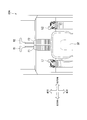
- FIG. 3 is a diagram illustrating a configuration of a cab of the working machine according to the first embodiment.
- the operator's cab 32A is provided with operation levers L1, L2, foot pedals F1, F2, and traveling levers R1, R2.
- the operation lever L1 and the operation lever L2 are disposed on the left and right of the seat ST in the cab 32A.
- the foot pedal F1 and the foot pedal F2 are arranged in the cab 32A, in front of the seat ST, and on the floor.
- the operation lever L1 disposed on the left side toward the front of the driver's cab is an operation mechanism for performing a swing operation of the upper swing body 32 and an excavation / dump operation of the arm AR.
- the arm AR performs a dump operation.
- the arm AR excavates.
- the upper swing body 32 turns right.
- the operator of the work machine 3 tilts the operation lever L1 to the left the upper swing body 32 turns left.
- the operation lever L1 is tilted in the front-rear direction
- the upper swing body 32 may turn right or left
- the arm AR may perform a dumping operation or an excavation operation.
- the operation lever L2 disposed on the right side toward the front of the cab is an operation mechanism for performing the excavation / dump operation of the bucket BK and the raising / lowering operation of the boom BM. Specifically, when the operator of the work machine 3 tilts the operation lever L2 forward, a lowering operation of the boom BM is performed. When the operator of the work machine 3 tilts the operation lever L2 backward, the operation of raising the boom BM is performed. When the operator of the work machine 3 tilts the operation lever L2 rightward, a dump operation of the bucket BK is performed. Further, when the operator of the work machine 3 tilts the operation lever L2 to the left, an excavation operation of the bucket BK is performed.
- the traveling levers R1 and R2 are operation mechanisms for controlling the operation of the lower traveling body 31, that is, controlling the traveling of the work machine 3.
- the traveling lever R1 disposed on the left side toward the front of the cab corresponds to the rotational driving of the left crawler belt CL of the lower traveling body 31. Specifically, when the operator of the work machine 3 tilts the traveling lever R1 forward, the left crawler belt CL rotates in the forward direction. When the operator of the work machine 3 tilts the traveling lever R1 backward, the left crawler belt CL rotates in the reverse direction.
- the traveling lever R2 disposed on the right side toward the front of the cab corresponds to the rotational driving of the right crawler belt CR of the lower traveling body 31. Specifically, when the operator of the work machine 3 tilts the traveling lever R2 forward, the right crawler belt CR rotates in the forward direction. When the operator of the work machine 3 tilts the traveling lever R2 backward, the right crawler belt CR rotates in the reverse direction.
- the foot pedals F1 and F2 are linked with the travel levers R and R2, respectively, and the travel can be controlled by the foot pedals F1 and F2.
- the work machine 3 described with reference to FIG. 2 may not include the GPS antennas G1 and G2.
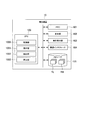
- FIG. 4 is a diagram illustrating a functional configuration of the playback device according to the first embodiment.
- the playback device 10 includes a CPU 100, a memory 101, a display unit 102, an operation reception unit 103, a communication interface 104, and a storage 105.
- the CPU 100 may be a processor such as an FPGA or a GPU instead of the CPU.
- the CPU 100 is a processor that controls the entire operation of the playback device 10. Various functions of the CPU 100 will be described later.
- the memory 101 is a so-called main storage device. In the memory 101, instructions and data necessary for the CPU 100 to operate based on the program are developed.
- the display unit 102 is a display device capable of visually displaying information, and is, for example, a liquid crystal display or an organic EL display.
- the operation receiving unit 103 is an input device, for example, a general mouse, keyboard, touch sensor, or the like.
- the communication interface 104 is a communication interface for communicating with the data logger 20.
- the storage 105 is a so-called auxiliary storage device, and is, for example, an HDD (Hard Disk Drive) or an SSD (Solid State Drive).
- HDD Hard Disk Drive
- SSD Solid State Drive
- log information TL received from the data logger 20 a vehicle type of the work machine 3, a work machine model TM prepared in advance for each model, and the like are recorded.
- the work machine model TM will be described later.
- the CPU 100 of the playback device 10 By operating based on a predetermined program, the CPU 100 exhibits functions as the acquisition unit 1000, the reception unit 1001, the extraction unit 1002, and the reproduction unit 1003.
- the predetermined program may be for realizing a part of the function to be exhibited by the playback device 10.
- the program may be such that the function is exhibited by a combination with another program already stored in the storage 105 or a combination with another program mounted on another device.
- the playback device 10 may include a custom LSI (Large Scale Integrated Circuit) such as a PLD (Programmable Logic Device) in addition to or instead of the above configuration.
- Examples of the PLD include a PAL (Programmable Array Logic), a GAL (Generic Array Logic), a CPLD (Complex Programmable Logic Device), and an FPGA (Field Programmable Gate Array).
- PAL Programmable Array Logic
- GAL Generic Array Logic
- CPLD Complex Programmable Logic Device
- FPGA Field Programmable Gate Array
- the acquisition unit 1000 acquires log information TL to be reproduced from a plurality of log information TLs recorded and accumulated in the storage 105.
- the plurality of pieces of log information TL are recorded in the storage 105 for each file recorded under different file names.
- the receiving unit 1001 receives a predetermined reproduction instruction from the operator of the reproduction device 10. For example, the receiving unit 1001 receives a reproduction instruction of the work machine 3 from an operator of the reproduction device 10.
- the extraction unit 1002 extracts information used for reproducing the work machine 3 from the acquired log information TL.
- the reproducing unit 1003 applies the extracted angle information of the work machine 3 to the work machine model TM corresponding to the work machine 3 and reproduces it.
- FIG. 5 is a diagram showing a processing flow of the playback device according to the first embodiment.
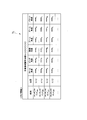
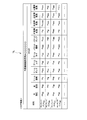
- 6 to 8 are first to third diagrams showing examples of log information according to the first embodiment.
- FIG. 9 is a diagram illustrating an example of a work machine model according to the first embodiment.
- the processing flow illustrated in FIG. 5 is started from a point in time when the dedicated application is started by the operator of the playback device 10.
- the receiving unit 1001 of the CPU 100 receives the specification of the log information TL to be reproduced (step S00).
- the operator of the playback device 10 specifies the log information TL to be played by, for example, inputting the file name of the log information TL or the like. Note that the log information TL to be reproduced may be fixed, and the log information TL may not be specified.
- the log information TL includes work machine identification information.
- the work machine identification information is, specifically, an individual identification number for individually identifying the work machine 3.
- the work machine identification information is allocated so as to correspond to the vehicle type, model, model, machine number, and the like of the work machine 3 indicating a hydraulic shovel, a wheel loader, and the like.
- the log information TL includes information indicating the position and orientation of the work machine 3 at each time, and angle information of the movable part of the work machine 3.
- the log information TL includes the position of the work machine 3, the roll angle of the work machine 3, which is the inclination of the machine in the left-right direction, the pitch angle, which is the inclination of the machine in the front-rear direction, the turning angle, the boom angle, The arm angle and the bucket angle are recorded at each time.
- the data logger 20 mounted on the work machine 3 is, for example, information obtained by receiving the GPS antennas G1 and G2, and determines the position of the work machine 3 based on positioning information indicating latitude and longitude. Identify and record.
- the data logger 20 calculates and records the roll angle and the pitch angle of the work machine 3 based on the measurement result of an IMU (Inertial Measurement Unit) mounted on the work machine 3.
- the data logger 20 calculates and records the turning angle of the upper swing body 32 based on the positioning information obtained from each of the GPS antennas G1 and G2 provided on the upper swing body 32.
- the data logger 20 calculates and records a boom angle, an arm angle, and a bucket angle based on the respective degrees of expansion and contraction of the boom cylinder SL1, the arm cylinder SL2, and the bucket cylinder SL3.
- the position, roll angle, and pitch angle are information necessary for specifying the position and posture of the work machine 3 itself. Therefore, for example, in the embodiment in which only the movement of the movable part of the work machine 3, that is, the upper revolving unit 32, the boom BM, the arm AR, and the bucket BK are reproduced as animation, and the position and posture of the work machine 3 are not reproduced. , Position, roll angle and pitch angle information need not be included in the log information.
- the log information TL includes pilot oil pressure (PPC pressure) indicating the degree of input to the operating levers L1, L2, etc. by the operator at each time, that is, the degree of tilt of the lever and the degree of depression of the pedal. ) Is included.
- the log information TL includes each operation type of left / right turning, arm excavation / dump, boom raising / lowering, bucket excavation / dump, right crawler forward / reverse, left crawler forward / reverse by the operator.
- the PPC pressure of the operating levers L1, L2, the running levers R1, R2, or the foot pedals F1, F2 is recorded at each time.
- Each time shown in FIG. 7 corresponds to each time in FIG.
- the log information TL includes information indicating the status of the main drive mechanism such as the engine and the hydraulic pump of the work machine 3 at each time. Specifically, in the log information TL, the engine coolant temperature, the engine output, the instantaneous fuel consumption, and the oil temperature of the hydraulic pump are recorded at each time. Each time shown in FIG. 8 corresponds to each time in FIGS. 6 and 7.
- the obtaining unit 1000 of the CPU 100 expands and obtains the specified log information TL in the memory 101 (step S01).
- the acquiring unit 1000 refers to the work machine identification information included in the log information TL.
- the acquiring unit 1000 selects and reads out the work machine model TM corresponding to the referred work machine identification information from the storage 105 (Step S02).
- the designation of the work machine model TM may be fixed without selecting the work machine model TM.
- the work machine model TM is information including work machine identification information, an external 3D model M0 of the work machine 3 indicated by the work machine identification information, an operation panel model M1, and the like.
- the external 3D model M0 is a 3D model representing the work machine 3, and is constructed for each part of the work machine 3, such as a lower traveling structure and an upper revolving structure.
- the external 3D model M0 represents the shape of the work machine 3.
- the outer 3D model M0 includes a lower traveling body outer model M01 representing the lower traveling body 31 of the work machine 3, an upper revolving body outer model M02 representing the upper revolving superstructure 32, a boom outer model M03 representing the boom BM, It is composed of an arm outline model M04 representing the arm AR and a bucket outline model M05 representing the bucket BK.
- the operation panel model M1 is a model representing the operation panel of the work machine 3 specified by the work machine identification information, and corresponds to the operation levers L1, L2 and the travel levers R1, R2 by the operator of the work machine 3.
- the input direction and the input degree are reproduced.
- the operation panel model M1 includes operation types of the work machine 3 (right / left turning, arm excavation / dump, boom raising / lowering, bucket excavation / dump, right crawler forward / reverse, left crawler forward / reverse (see FIG. 7). ) And the input operation type (operation lever L1 forward, operation lever L2 right direction,...) Of the operator of the work machine 3 are included.
- the receiving unit 1001 receives a reproduction instruction (step S03).
- One mode of the reproduction instruction may be an operation such as pressing a reproduction button.
- a reproduction instruction may be issued including information serving as a start point of reproduction, such as a time, a position of the work machine 3, and various events such as an abnormality occurring in the work machine 3.
- the extraction unit 1002 of the CPU 100 extracts information used for reproduction from the log information TL (Step S04). For example, various pieces of angle information such as a boom angle, an arm angle, and a bucket angle are extracted as information used for reproduction. Note that the pilot oil pressure shown in FIG. 7 may be extracted as information used for regeneration. In step S01, only information used for reproduction may be obtained.
- the CPU 100 refers to the position of the work machine 3 at each time indicated in the log information TL and draws the movement locus of the work machine 3 on a 2D map that is an overhead view image of the work site.
- the moving trajectory of the work machine 3 is drawn while sequentially applying the position of the work machine 3 at each time indicated in the log information TL to a 2D map which is an overhead view image of the work site, starting from the one with the oldest time stamp. I do.
- step S03 when the reproduction instruction including the time is received, the position of the work machine 3 indicated in the log information TL corresponding to the time is sequentially reduced from the one with the oldest time stamp to the work site.
- the moving trajectory of the work machine 3 may be drawn while being applied on a 2D map which is an image.
- the position of the work machine 3 indicated in the log information TL corresponding to the time that is a predetermined time before the time is sequentially applied to the 2D map that is the bird's-eye view image of the work site from the one with the oldest time stamp,
- the movement locus of the work machine 3 may be drawn.
- step S03 If the reproduction instruction including the position is received in step S03, the position of the work machine 3 indicated in the log information TL corresponding to the position is sequentially changed from the one with the oldest time stamp to the bird's-eye view of the work site.
- the moving trajectory of the work machine 3 may be drawn while being applied on a 2D map which is an image.
- the extraction unit 1002 refers to the status (FIG. 8) regarding the drive mechanism such as the engine and the hydraulic pump of the work machine 3 at each time indicated in the log information TL, and determines the drive mechanism on the movement locus of the work machine 3. Is extracted (hereinafter, also referred to as an abnormality occurrence section).
- the CPU 100 draws the abnormality occurrence section on the display unit 102 so as to overlap the movement locus (step S05). In another embodiment, the drawing process in step S05 may be performed at the timing of step S06, which will be described later, or at a later step.
- the reproducing unit 1003 executes an animation reproducing process of the work machine model TM (Step S06).
- the reproduction unit 1003 performs animation reproduction of the work machine 3 while sequentially applying the various information recorded in the log information TL to the work machine model TM from the oldest time stamp.
- the reproduction instruction including the time when the reproduction instruction including the time is received, the work machine 3 performs animation reproduction while sequentially applying various information corresponding to the time to the work machine model TM.
- step S03 when a reproduction instruction including a position and various events has been received, various information corresponding to the time at the position and the time at which various events occurred are sequentially applied to the work machine model TM.
- the work machine 3 is animated while playing.
- the reproducing unit 1003 changes the angle of the corresponding portion of the external 3D model M0 based on various angle information such as the turning angle and the boom angle indicated in the log information TL. For example, the reproducing unit 1003 tilts the bucket outer shape model M05 around a rotation axis defined at a connection position with the arm outer shape model M04 so as to have a bucket angle indicated by the log information TL, and thereby the work machine 3 The position and posture of the bucket BK are reproduced.
- the reproducing unit 1003 tilts the arm external model M04 around the rotation axis defined at the connection position with the boom external model M03 so as to have the arm angle indicated in the log information TL, and thereby the work machine 3 The position and posture of the arm AR are reproduced.
- the reproducing unit 1003 tilts the upper revolving unit outer shape model M02 around the rotation axis defined at the connection position with the lower traveling unit outer shape model M01 so as to have the turning angle indicated by the log information TL.
- the position and posture of the upper swing body 32 of the work machine 3 are reproduced.
- the reproducing unit 1003 tilts the lower traveling body outer shape model M01 around the roll rotation axis defined by the lower traveling body outer shape model M01 so as to have a roll angle indicated by the log information TL, and
- the attitude of the upper revolving unit 32 of the work machine 3 is reproduced by inclining around the pitch rotation axis defined in the body outline model M01 so as to have the pitch angle indicated by the log information TL.
- the playback device 10 performs animation playback of the traveling of the work machine 3 based on the PPC pressures of the right crawler advance / reverse and the left crawler advance / reverse at each time included in the log information TL. Can be.
- the external 3D model M0 is moved forward, backward, left and right forward, and left and right backward.
- the outer shape 3D model M0 is moved in the forward direction based on the numerical values of the PPC pressures of the right crawler advance and the left crawler advance.
- the moving speed may be changed based on the numerical value of the PPC pressure.
- the outer shape 3D model M0 is moved backward. Further, based on a difference between the numerical values of the PPC pressures of the right crawler advance and the left crawler advance, the outer shape 3D model M0 is moved so as to curve forward and left and right. For example, when the numerical value of the PPC pressure of the right crawler advance is larger than the numerical value of the PPC pressure of the left crawler advance, the vehicle is moved so as to curve forward and leftward. The moving speed and the size of the curve may be changed according to the respective PPC pressure values and the difference between the PPC pressure values.
- the 3D model M0 is moved so as to curve backward and leftward on the basis of the difference between the numerical values of the PPC pressures of the right crawler retreat and the left crawler retreat.
- the vehicle is moved so as to curve backward and leftward.
- the moving speed and the size of the curve may be changed according to the respective PPC pressure values and the difference between the PPC pressure values.
- the traveling of the work machine 3 can be more accurately animated.
- the position information in addition to the PPC pressures of the right crawler forward / reverse and the left crawler forward / reverse, the traveling of the work machine 3 can be more accurately animated.
- the moving speed and the position of the work machine 3 can be more accurately expressed.
- the work machine 3 in addition to the PPC pressures of the right crawler advance / reverse and the left crawler advance / reverse, the work machine 3 is animated on the basis of the roll angle, the pitch angle, or both the roll angle and the pit angle. The inclination of the work machine 3 in the left-right direction during traveling or the inclination of the work machine 3 in the front-rear direction can be reproduced.
- the reproducing unit 1003 sequentially displays the PPC pressures of the operation levers L1 and L2 and the traveling levers R1 and R2 for each operation type indicated by the log information TL, starting from the one with the oldest time stamp, and operating the operation panel of the work machine model TM.
- the model M1 By applying to the model M1, an input operation by the operator of the work machine 3 on various operation levers and traveling levers is reproduced as animation.
- the playback unit 1003 simultaneously plays back animations on the same screen while adjusting the playback times of the external 3D model M0 and the operation panel model M1.
- the reproducing unit 1003 determines whether or not to end the animation reproduction during the animation reproduction processing of the work machine 3 (Step S07). For example, when an instruction to end the reproduction based on the pressing of the stop button or the like is received, it is determined that the animation reproduction is to be ended. After a predetermined period has elapsed after the start of the animation reproduction, it may be determined that the animation reproduction is to be ended. When the animation reproduction does not end (Step S07; NO), the reproduction unit 1003 continues the animation reproduction of the work machine model TM. On the other hand, when ending the animation reproduction (step S07; YES), the reproduction unit 1003 ends the animation reproduction processing.
- Steps S00, S02, S04, S05, and S07 of the processing flows described with reference to FIG. 5 are not indispensable components of the playback device 10, and other embodiments do not include such steps. You may.
- FIG. 11 shows a processing flow of the playback device when a playback period is received as a playback instruction.
- the receiving unit 1001 of the CPU 100 receives the specification of the log information TL to be reproduced (step S20).
- the operator of the playback device 10 specifies the log information TL to be played by, for example, inputting the file name of the log information TL or the like. Note that the log information TL to be reproduced may be fixed, and the log information TL may not be specified.
- the obtaining unit 1000 of the CPU 100 expands the specified log information TL in the memory 101 and obtains it (step S21).
- the acquiring unit 1000 refers to the work machine identification information included in the log information TL.
- the acquisition unit 1000 selects and reads the work machine model TM corresponding to the referenced work machine identification information from the storage 105 (Step S22).
- the designation of the work machine model TM may be fixed without selecting the work machine model TM.
- the receiving unit 1001 receives a reproduction period (reproduction start time and reproduction end time) as a reproduction instruction from the operator of the reproduction device 10 (step S23).
- the extraction unit 1002 of the CPU 100 extracts information on the state of the work machine 3 from the reproduction start time to the reproduction end time from the log information TL (step S24).
- the CPU 100 refers to the position of the work machine 3 at each time indicated in the log information TL (FIG. 6) and draws the movement locus of the work machine 3 on a 2D map that is an overhead image of the work site. .
- the extraction unit 1002 refers to the status (FIG. 8) regarding the drive mechanism such as the engine and the hydraulic pump of the work machine 3 at each time indicated in the log information TL, and determines the drive mechanism on the movement locus of the work machine 3. Is extracted (hereinafter, also referred to as an abnormality occurrence section).
- the CPU 100 draws the abnormality occurrence section on the display unit 102 so as to overlap the movement locus (step S25). In another embodiment, the drawing processing of the abnormality occurrence section in step S25 may be performed at the timing of step S27 to be described later, or at a later step.
- the playback unit 1003 of the CPU 100 determines whether or not an instruction to start playback has been received from the operator of the playback device 10 (step S26). If a reproduction start instruction has not been received (step S26; NO), the process stands by until a reproduction start instruction is received.
- the reproduction unit 1003 executes an animation reproduction process of the work machine model TM (Step S27).
- the reproduction unit 1003 reproduces the animation of the work machine 3 while applying the information extracted in S24 to the work machine model TM sequentially from the one with the oldest time stamp.
- the reproduction unit 1003 determines whether the animation reproduction has ended (step S28). If the animation reproduction has not ended (step S28; NO), the reproduction unit 1003 continues the animation reproduction of the work machine model TM. On the other hand, when the animation reproduction has ended (step S28; YES), the reproduction unit 1003 ends the animation reproduction processing.
- the playback unit 1003 ends the animation playback process, for example, when receiving an animation stop operation by the operator of the playback device 10 or when the playback time reaches the playback end time.
- Steps S20, S22, S25, S26, and S28 of the processing flows described with reference to FIG. 11 are not indispensable components of the playback device 10, and other embodiments do not include such steps. You may.
- FIG. 10 is a diagram illustrating an example of a display screen of the playback device according to the first embodiment.
- the CPU 100 of the playback device 10 according to the first embodiment causes the display unit 102 to display a display image D as shown in FIG. 10, for example.
- the display image D includes an input form D0, an external 3D model display image D1, an information list image D2, a 2D map image D3, a time scroll bar D4, and an operation pattern image D5.
- the input form D0 is an area where an image for accepting the specification of the log information TL and the reproduction period (start time, end time) from the operator of the reproduction device 10 is drawn.
- the operator of the playback device 10 inputs desired information into the input form D0. For example, when specifying the log information TL, the file name of the log information TL is input. When the start time and the end time of the reproduction are designated, the start time and the end time are input.
- the outer shape 3D model display image D1 is an area where the outer shape 3D model M0 is played back by animation.
- a work machine image D10 in which various information such as a boom angle, an arm angle, and a bucket angle indicating the state of the work machine 3 are applied to the external 3D model M0 (FIG. 9) is drawn.
- a button image D11 for the operator of the playback device 10 to instruct animation playback, pause, and the like is drawn on the external 3D model display image D1.
- the information list image D2 is an area for presenting various types of information related to reproduction to an operator of the reproduction device 10.
- the information list image D2 includes the reproduction time, the vehicle type and model of the work machine model TM being reproduced, the presence / absence of an abnormality in the reproduction time, and the like.
- the # 2D map image D3 is an area where an overhead image of the work machine 3 is drawn.
- a work machine icon D30, a movement trajectory D31, and an abnormality occurrence section D32 are drawn in addition to the 2D map image which is an overhead view image of the work site.
- the work machine icon D30 is an image indicating the position and orientation of the work machine 3 being reproduced on the 2D map.
- the movement trajectory D31 indicates the trajectory of the movement of the work machine 3 in the 2D map.
- the work machine icon D30 and the movement trajectory D31 are drawn based on the position of the work machine 3 at each time included in the log information TL.
- the abnormality occurrence section D32 indicates a section of the movement trajectory D31 where an abnormality has occurred in the drive mechanism of the work machine 3 such as the engine and the hydraulic pump.
- the abnormality occurrence section D32 is drawn based on the status of the drive mechanism of the work machine 3 (FIG. 8). For example, the CPU 100 extracts, from the movement locus D31 of the work machine 3, a section in which the engine coolant temperature exceeds a predetermined abnormality determination threshold, and draws the section as an abnormality occurrence section D32.
- the operator of the playback device 10 may be able to change the playback time as desired, for example, by using the operation reception unit 103 such as a mouse to specify a predetermined position on the movement trajectory D31 or perform an operation such as a click. .
- the time scroll bar D4 is a scroll bar for controlling animation reproduction.
- the time scroll bar D4 includes a bar image D40 representing a time axis from the start time to the end time, a playback time icon D41 corresponding to a time being played on the time axis indicated by the bar image D40, and an abnormality occurrence time zone. D42 is drawn.
- the playback time icon D41 is displayed at a position corresponding to the playback time in the bar image D40. The operator can change the reproduction time as desired by performing an operation of sliding the reproduction time icon D41 on the bar image D40.
- the abnormality occurrence time period D42 is a time period corresponding to the abnormality occurrence section D32 of the 2D map image D3, and indicates a time period in which an abnormality occurs in the drive mechanism of the work machine 3 from the start time to the end time. .
- the operator of the playback device 10 may change the playback time as desired by performing an operation of sliding the playback time icon D41 on the bar image D40 using the operation reception unit 103.
- the operation pattern D5 is a region where the input operation of the operation lever and the travel lever by the operator of the work machine 3 is reproduced as an animation.
- the operation pattern D5 includes operation images D50, D51, D52, and D53 and operation icons D501, D511, D521, and D531.
- the operation image D50 is a region where the input operation to the operation lever L1, which is the left operation lever, is animated and reproduced.
- the position of the operation icon D501 on the operation image D50 indicates the input direction to the operation lever L1.
- the color of the operation icon D501 displayed on the operation image D50 indicates the degree of input to the operation lever L1. For example, when there is no input to the operation lever L1, the icon D501 is displayed in full “white", and is displayed so as to change from “white” to “red” as the degree of input increases.
- the combination of colors that changes according to the input degree is not limited to this example. The same applies to icons D511, D521, and D531, which will be described later.
- the operation image D51 is an area where the input operation to the operation lever L2, which is the right operation lever, is animated and reproduced.
- the position of the operation icon D511 on the operation image D51 indicates the input direction to the operation lever L2.
- the color of the operation icon D511 displayed on the operation image D51 indicates the degree of input to the operation lever L2.
- the operation image D52 is a region where the input operation to the traveling lever R1, which is the left traveling lever, is reproduced as an animation.
- the position of the operation icon D521 on the operation image D52 indicates the input direction to the travel lever R1.
- the color of the operation icon D521 displayed on the operation image D52 indicates the degree of input to the travel lever R1.
- the operation image D53 is an area where the input operation to the traveling lever R2, which is the right traveling lever, is animated and reproduced.
- the position of the operation icon D531 on the operation image D53 indicates the input direction to the traveling lever R2.
- the color of the operation icon D531 displayed on the operation image D53 indicates the degree of input to the travel lever R2.
- the playback device 10 includes the acquisition unit 1000 that acquires the log information TL including the angle information of the movable unit of the work machine 3 associated with the time, and the reproduction of the operation of the work machine 3
- the receiving unit 1001 that receives the instruction and the reproducing unit 1003 that reproduces the operation of the work machine 3 by sequentially applying the angle information of the movable part of the work machine 3 to the work machine model TM when the reproduction instruction is received. Prepare.
- the playback device 10 is configured to use the outer shape 3D model indicating the outer shape of the work machine 3 based on the information included in the log information TL that can specify the position and orientation of each part of the work machine 3.
- the animation of M0 is reproduced.
- the appearance movement of the work machine 3 at the actual work site is reproduced by the 3D model representing the work machine 3, so that the work performed by the work machine 3 at the work site can be analyzed in detail. .
- the playback device 10 uses a work machine based on the PPC pressure indicating the degree of input to the operation mechanisms such as the operation levers L1 and L2 and the traveling levers R1 and R2 included in the log information TL.
- the animation reproduction of the operation panel model M1 showing the operation mechanism 3 is performed.
- the operation mode of the operator of the work machine 3 at the actual work site is reproduced by the operation panel model M1 representing the operation mechanism of the work machine 3, so that the operator of the work machine 3 performs the operation at the work site. It is possible to analyze the manner of maneuver in detail after the fact.
- the playback device 10 simultaneously plays back the external 3D model and the operation panel model M1 while adjusting the playback time. By doing so, it is possible to analyze the correspondence between the input operation by the operator and the movement of the work machine 3 based on the input operation.
- the playback device 10 extracts, from the log information TL, an abnormality occurrence time zone indicating a time zone in which the state of the work machine 3 has become abnormal, and displays the abnormality occurrence time zone on, for example, a time scroll bar D4. I do.
- the operator of the reproducing device 10 can easily grasp the time zone in which the abnormality has occurred in the work machine 3.
- the operator can analyze the cause of the abnormality by designating and displaying the displayed abnormality occurrence time zone to be included in the reproduction period.
- the reproducing device 10 reproduces a change in the position of the work machine 3 on the two-dimensional map based on the position of the work machine 3 at each time included in the log information TL. In this way, the change in the position of the work machine 3 at the work site can be grasped in detail.
- the reproducing device 10 displays the section where the abnormality has occurred in the work machine 3 on the movement trajectory D31. By doing so, it is possible to analyze at what position in the work site the abnormality has occurred.
- the reproducing apparatus 10 according to the first embodiment and the analysis support system 1 including the same have been described in detail, but other embodiments are not limited to the above-described embodiment.
- the contents of the log information TL (FIGS. 6 to 8) according to the first embodiment are not limited to this in other embodiments.
- log information TL corresponding to the vehicle type is recorded.
- the other vehicle type is, for example, a wheel loader.
- a model representing the outer shape and operation panel of the work machine 3 is prepared for each vehicle type and model of the work machine 3.
- the log information TL includes the position of the work machine 3 at each time, the angles of various movable parts (FIG. 6), the PPC pressure in the operation mechanism (FIG. 7), and the Although the status of the driving mechanism (FIG. 8) has been described as being included, other embodiments are not limited to this.
- the playback device 10 may acquire only the information according to FIG. 6 as the log information TL.
- the playback device 10 performs animation playback of only the operation of the work machine 3 based on the log information TL.
- the playback device 10 may acquire only the information according to FIG. 7 as the log information TL.
- the playback device 10 can play back the animation of the traveling of the work machine 3 and the input operations on the various operation levers and the travel lever of the work machine 3.
- the playback device 10 has been described as including both the external 3D model M0 and the operation panel model M1 as the work machine model TM and playing back both, but in other embodiments, It is not limited to this embodiment.
- the reproduction device 10 according to another embodiment reproduces only one of the external 3D model M0 and the operation panel model M1 in the work machine model TM including one of the external 3D model M0 and the operation panel model M1. It may be.
- the playback device 10 may be configured to change which of the external 3D model M0 and the operation panel model M1 is to be played back by setting.
- reproducing device 10 Although the reproducing device 10 according to the first embodiment reproduces a change in the position of the work machine 3 on the 2D map, the reproducing device 10 is not limited to this mode in other embodiments.
- the playback device 10 according to another embodiment may be a mode in which a change in the position of the work machine 3 on the 2D map is not played back.
- the playback device 10 according to the first embodiment has been described as displaying the abnormality occurrence section on the 2D map and the abnormality occurrence time zone on the time scroll bar.
- this mode is used. It is not limited to.
- the playback device 10 according to another embodiment may be a mode in which the abnormality occurrence section on the 2D map or the abnormality occurrence time zone on the time scroll bar is not displayed.
- the playback device 10 may have not only normal speed playback but also fast forward, slow playback, repeat, and rewind functions.
- the reproducing unit 1003 reproduces the data using 30 pieces of angle information per second or the like, or outputs 15 pieces of angle information or the like per second.
- a double-speed fast forward function is realized by using skipping.
- a fast forward function such as triple speed can be realized by a similar mechanism.
- the playback unit 1003 reproduces the 15 pieces of angle information or the like in 2 seconds to perform a 1/2 speed slow playback function.
- the trainee can grasp the lever operation skill of the expert in more detail.
- the rewind reproduction is realized by sequentially applying and reproducing the time stamp from the new one.
- the degree of input to each operating mechanism has been described as being represented by the PPC pressure. Is not limited to this embodiment.
- the operation mechanism may be an electric operation mechanism.
- the various operation mechanisms may include an operation member such as an electric lever and an operation amount sensor such as a potentiometer inclinometer that electrically detects the amount of tilt of the operation member.
- detection data of the operation amount sensor is recorded in the data logger 20.
- the playback device 10 according to the first embodiment has been described as representing the work machine 3 by the external 3D model M0, the embodiment is not limited to this mode in other embodiments.
- the playback device 10 according to another embodiment may, for example, represent the work machine 3 by a 2D model.
- the playback device 10 according to the first embodiment has been described as expressing the degree of input by the operating mechanism of the operator by a change in color of the icon D501 or the like shown in the operation pattern D5.
- the configuration is not limited to this mode.
- the playback device according to another embodiment may indicate the degree of input at a position where the icon D501 or the like is drawn.
- the reproduction device 10 is drawn at a position closer to the center of the operation image D50, and as the degree of input to the operation lever L1 increases, the center of the operation image D50 increases. It is drawn at a position away from.
- the input degree may be indicated by the intensity of the gradation of the color drawn in the operation image D50.
- the playback device 10 is installed at a location away from the work machine 3 and is connected to a data logger 20 mounted on the work machine 3 via a wide area communication network.
- a data logger 20 mounted on the work machine 3 via a wide area communication network.
- a part or the entire configuration of the playback device 10 may be installed inside the work machine 3.
- the data logger 20 may transmit the log information TL to the playback device 10 via a network or the like inside the work machine 3 without passing through the wide area communication network.
- the operator who gets on the work machine 3 can confirm the movement of the work machine 3 operated by the operator by playing the animation on the spot. Further, by reproducing the movement of the working machine 3 serving as a model for the operator of the working machine 3, the movement can be used as guidance.
- the reproducing device 10 installed inside the work machine 3 may acquire the log information TL of another work machine 3 via a wide area communication network or the like. By doing so, the state of the work machine 3 other than the work machine 3 on which the playback device 10 is mounted can be played back by animation.
- the playback device 10 transmits video information generated by the animation playback process to a monitor mounted on the work machine 3 and displays the video information, while being installed at a location away from the work machine 3. It may be.
- the position of the work machine 3 shown on the screen on the 2D map may be designated.
- the reproduction device 10 reproduces the work machine 3 with the time at which the work machine 3 is present at the position designated by the operator as the reproduction start time.
- the specification of the reproduction end time is not essential in other embodiments.
- only a playback start time may be accepted as a playback instruction from the operator, and playback may be performed for a certain period of time from the playback start time, or playback may be continued as long as log information exists.
- the reproduction may be stopped in response to the occurrence of other various events.
- the reproduction unit 1003 may apply the information used for reproduction in the log information TL to the work machine model TM in a time series.
- the processes of the above-described various processes of the playback device 10 are stored in a computer-readable recording medium in the form of a program, and the various processes are performed by reading and executing the program by a computer.
- the computer-readable recording medium includes a magnetic disk, a magneto-optical disk, a CD-ROM, a DVD-ROM, a semiconductor memory, and the like.
- the computer program may be distributed to a computer via a communication line, and the computer that has received the distribution may execute the program.
- the program may be for realizing a part of the functions described above. Furthermore, a program that can realize the above-described functions in combination with a program already recorded in the computer system, a so-called difference file, a difference program, or the like may be used.
- the movement of the work machine based on the operation of the operator can be reproduced on the screen and analyzed.
Landscapes
- Engineering & Computer Science (AREA)
- Mining & Mineral Resources (AREA)
- Civil Engineering (AREA)
- General Engineering & Computer Science (AREA)
- Structural Engineering (AREA)
- Mechanical Engineering (AREA)
- Paleontology (AREA)
- General Life Sciences & Earth Sciences (AREA)
- Life Sciences & Earth Sciences (AREA)
- Physics & Mathematics (AREA)
- General Physics & Mathematics (AREA)
- Theoretical Computer Science (AREA)
- Operation Control Of Excavators (AREA)
- Component Parts Of Construction Machinery (AREA)
- Processing Or Creating Images (AREA)
- Debugging And Monitoring (AREA)
Abstract
本発明に係る再生装置は、時刻に対応付けられる作業機械の可動部の角度情報を含むログ情報を取得する取得部と、前記作業機械の動作の再生指示を受け付ける受付部と、前記再生指示を受付けた場合、前記角度情報を、作業機械モデルに順次適用することで、前記作業機械の動作を再生する再生部と、を備える。
Description
本発明は、再生装置、分析支援システム及び再生方法に関する。
本願は、2018年9月14日に日本に出願された特願2018-172845号について優先権を主張し、その内容をここに援用する。
本願は、2018年9月14日に日本に出願された特願2018-172845号について優先権を主張し、その内容をここに援用する。
特許文献1には、専用のカメラ搭載車を現場に配置することなく、操作者の作業を支援し、かつ作業機械と運搬車両との相対位置情報を含む支援画像を生成することのできる作業支援画像生成装置、及びそれを備えた作業機械の遠隔操縦システムが開示されている。
作業機械の運転、操作に関する分野において、自分の操作を振り返りたい、熟練の操作者の動きを知りたい、作業機械の故障時、作業機械の異常時の動きを知りたい、等のニーズがある。そこで、操作者の操作に基づく作業機械の動きを忠実に再現することで、作業機械の動きを詳細に分析できるツールの開発が求められている。
上述の課題に鑑みて、本発明は、作業機械の操作者の操作に基づく当該作業機械の一連の動作を画面上で再生し、事後的に分析できる再生装置、分析支援システム及び再生方法を提供することを目的とする。
本発明の一態様によれば、再生装置は、時刻に対応付けられる作業機械の可動部の角度情報を含むログ情報を取得する取得部と、前記作業機械の動作の再生指示を受け付ける受付部と、前記再生指示を受付けた場合、前記角度情報を、作業機械モデルに順次適用することで、前記作業機械の動作を再生する再生部と、を備える。
上記態様によれば、操作者の操作に基づく作業機械の動きを画面上で再生し、分析できる。
<第1の実施形態>
以下、第1の実施形態に係る再生装置、及び、これを備える分析支援システムについて、図1~図10を参照しながら詳細に説明する。
以下、第1の実施形態に係る再生装置、及び、これを備える分析支援システムについて、図1~図10を参照しながら詳細に説明する。
(分析支援システムの全体構成)
図1は、第1の実施形態に係る分析支援システムの全体構成を示す図である。
分析支援システム1は、再生装置10と、複数の作業機械3のそれぞれに搭載されたデータロガー20とを有している。
図1は、第1の実施形態に係る分析支援システムの全体構成を示す図である。
分析支援システム1は、再生装置10と、複数の作業機械3のそれぞれに搭載されたデータロガー20とを有している。
作業機械3は、再生装置10による作業分析の対象である。作業機械3の例としては、油圧ショベルやホイールローダなどが挙げられる。なお、以下の説明においては、作業機械3の例として油圧ショベルを挙げて説明する。各作業機械3には複数のセンサが設けられている。データロガー20は、当該センサによって取得された、作業機械3の状態を示す情報を時系列に記録、蓄積する。以下、データロガー20が記録した、各時刻における作業機械3の状態を示す情報をログ情報とも記載する。また、データロガー20は、記録したログ情報を一定時間間隔で、広域通信網を介して再生装置10に送信する。なお、一定時間間隔とは、例えば、5分間隔である。再生装置10は、データロガー20から受信したログ情報を記録媒体に記録する。
再生装置10の機能については後述する。
再生装置10の機能については後述する。
(作業機械の構造)
図2は、第1の実施形態に係る作業機械の構造を示す図である。
油圧ショベルである作業機械3は、作業現場等において土砂などを掘削、整地する。
図2に示すように、油圧ショベルである作業機械3は、走行するための下部走行体31と、下部走行体31の上部に設置され旋回可能な上部旋回体32とを有してなる。また、上部旋回体32には、運転室32A、作業機32B、及び、2つのGPSアンテナG1、G2が設けられている。
図2は、第1の実施形態に係る作業機械の構造を示す図である。
油圧ショベルである作業機械3は、作業現場等において土砂などを掘削、整地する。
図2に示すように、油圧ショベルである作業機械3は、走行するための下部走行体31と、下部走行体31の上部に設置され旋回可能な上部旋回体32とを有してなる。また、上部旋回体32には、運転室32A、作業機32B、及び、2つのGPSアンテナG1、G2が設けられている。
下部走行体31は、左側履帯CLと、右側履帯CRとを有する。作業機械3は、左側履帯CL及び右側履帯CRの回転により前進、旋回、後進する。
運転室32Aは、作業機械3の操作者が搭乗し、操作を行う場所である。運転室32Aは、例えば、上部旋回体32の前端部左側部分に設置される。運転室32A内部の構成については後述する。
作業機32Bは、ブームBM、アームAR及びバケットBKからなる。ブームBMは、上部旋回体32の前端部に装着される。また、ブームBMにはアームARが取り付けられる。また、アームARにはバケットBKが取り付けられる。また、上部旋回体32とブームBMとの間にはブームシリンダSL1が取り付けられる。ブームシリンダSL1を駆動することで上部旋回体32に対しブームBMを動作することができる。ブームBMとアームARとの間にはアームシリンダSL2が取り付けられる。アームシリンダSL2を駆動することで、ブームBMに対しアームARを動作することができる。アームARとバケットBKとの間にはバケットシリンダSL3が取り付けられる。バケットシリンダSL3を駆動することでアームARに対しバケットBKが動作することができる。
油圧ショベルである作業機械3が具備する上述の上部旋回体32、ブームBM、アームAR及びバケットBKは、作業機械3の可動部の一態様である。
油圧ショベルである作業機械3が具備する上述の上部旋回体32、ブームBM、アームAR及びバケットBKは、作業機械3の可動部の一態様である。
(運転室の構成)
図3は、第1の実施形態に係る作業機械の運転室の構成を示す図である。
図3は、第1の実施形態に係る作業機械の運転室の構成を示す図である。
図3に示すように、運転室32Aには、操作レバーL1、L2と、フットペダルF1、F2と、走行レバーR1、R2とが設けられている。
操作レバーL1及び操作レバーL2は、運転室32A内のシートSTの左右に配置される。また、フットペダルF1及びフットペダルF2は、運転室32A内、シートSTの前方、床面に配置される。
操作レバーL1及び操作レバーL2は、運転室32A内のシートSTの左右に配置される。また、フットペダルF1及びフットペダルF2は、運転室32A内、シートSTの前方、床面に配置される。
操作レバーL1、L2、走行レバーR1,R2に対する入力操作と、油圧ショベルである作業機械3の動作との対応関係を示す操作パターンの一例は、以下のとおりである。
運転室前方に向かって左側に配置される操作レバーL1は、上部旋回体32の旋回動作、及び、アームARの掘削/ダンプ動作を行うための操作機構である。具体的には、作業機械3の操作者が操作レバーL1を前方に倒すと、アームARがダンプ動作する。また、作業機械3の操作者が操作レバーL1を後方に倒すと、アームARが掘削動作する。また、作業機械3の操作者が操作レバーL1を右方向に倒すと、上部旋回体32が右旋回する。また、作業機械3の操作者が操作レバーL1を左方向に倒すと、上部旋回体32が左旋回する。操作レバーL1を前後方向に倒した場合に上部旋回体32が右旋回または左旋回し、操作レバーL1が左右方向に倒した場合にアームARがダンプ動作または掘削動作してもよい。
運転室前方に向かって右側に配置される操作レバーL2は、バケットBKの掘削/ダンプ動作、及び、ブームBMの上げ/下げ動作を行うための操作機構である。具体的には、作業機械3の操作者が操作レバーL2を前方に倒すと、ブームBMの下げ動作が実行される。また、作業機械3の操作者が操作レバーL2を後方に倒すと、ブームBMの上げ動作が実行される。また、作業機械3の操作者が操作レバーL2を右方向に倒すと、バケットBKのダンプ動作が行われる。また、作業機械3の操作者が操作レバーL2を左方向に倒すと、バケットBKの掘削動作が行われる。
また、走行レバーR1,R2は、下部走行体31の動作制御、すなわち作業機械3の走行制御を行うための操作機構である。
運転室前方に向かって左側に配置される走行レバーR1は、下部走行体31の左側履帯CLの回転駆動に対応する。具体的には、作業機械3の操作者が走行レバーR1を前方に倒すと、左側履帯CLは前進方向に回転する。また、作業機械3の操作者が走行レバーR1を後方に倒すと、左側履帯CLは後進方向に回転する。
運転室前方に向かって左側に配置される走行レバーR1は、下部走行体31の左側履帯CLの回転駆動に対応する。具体的には、作業機械3の操作者が走行レバーR1を前方に倒すと、左側履帯CLは前進方向に回転する。また、作業機械3の操作者が走行レバーR1を後方に倒すと、左側履帯CLは後進方向に回転する。
運転室前方に向かって右側に配置される走行レバーR2は、下部走行体31の右側履帯CRの回転駆動に対応する。具体的には、作業機械3の操作者が走行レバーR2を前方に倒すと、右側履帯CRは前進方向に回転する。また、作業機械3の操作者が走行レバーR2を後方に倒すと、右側履帯CRは後進方向に回転する。なお、フットペダルF1、F2は、それぞれ、走行レバーR,R2と連動しており、フットペダルF1、F2によって、走行制御することもできる。
なお、上述した操作パターンは一例にすぎず、油圧ショベルの機種等によっては上記の態様に限定されない。
なお、実施形態によっては、図2を用いて説明した作業機械3は、GPSアンテナG1、G2を備えないものであってもよい。
(再生装置の機能構成)
図4は、第1の実施形態に係る再生装置の機能構成を示す図である。
以下、図4を参照しながら、第1の実施形態に係る再生装置10の機能について説明する。
図4に示すように、再生装置10は、CPU100と、メモリ101と、表示部102と、操作受付部103と、通信インタフェース104と、ストレージ105とを備えている。なお、CPU100は、CPUではなく、FPGA、GPU等のプロセッサであってもよい。
図4は、第1の実施形態に係る再生装置の機能構成を示す図である。
以下、図4を参照しながら、第1の実施形態に係る再生装置10の機能について説明する。
図4に示すように、再生装置10は、CPU100と、メモリ101と、表示部102と、操作受付部103と、通信インタフェース104と、ストレージ105とを備えている。なお、CPU100は、CPUではなく、FPGA、GPU等のプロセッサであってもよい。
CPU100は、再生装置10の動作全体の制御を司るプロセッサである。CPU100が有する各種機能については後述する。
メモリ101は、いわゆる主記憶装置である。メモリ101には、CPU100がプログラムに基づいて動作するために必要な命令及びデータが展開される。
表示部102は、情報を視認可能に表示可能な表示デバイスであって、例えば、液晶ディスプレイや有機ELディスプレイなどである。
操作受付部103は、入力デバイスであって、例えば、一般的なマウス、キーボード、タッチセンサなどである。
通信インタフェース104は、データロガー20との間で通信するための通信インタフェースである。
ストレージ105は、いわゆる補助記憶装置であって、例えば、HDD(Hard Disk Drive)、SSD(Solid State Drive)等である。ストレージ105には、データロガー20から受信したログ情報TL、作業機械3の車両種類、機種ごとに事前に用意された作業機械モデルTMなどが記録される。なお、作業機械モデルTMについては、後述する。
第1の実施形態に係る再生装置10のCPU100が有する機能について詳しく説明する。CPU100は、所定のプログラムに基づいて動作することで、取得部1000、受付部1001、抽出部1002及び再生部1003としての機能を発揮する。
なお、上記所定のプログラムは、再生装置10に発揮させる機能の一部を実現するためのものであってもよい。例えば、プログラムは、ストレージ105に既に記憶されている他のプログラムとの組み合わせ、または他の装置に実装された他のプログラムとの組み合わせによって機能を発揮させるものであってもよい。なお、他の実施形態においては、再生装置10は、上記構成に加えて、または上記構成に代えてPLD(Programmable Logic Device)などのカスタムLSI(Large Scale Integrated Circuit)を備えてもよい。PLDの例としては、PAL(Programmable Array Logic)、GAL(Generic Array Logic)、CPLD(Complex Programmable Logic Device)、FPGA(Field Programmable Gate Array)が挙げられる。この場合、プロセッサによって実現される機能の一部または全部が当該集積回路によって実現されてよい。
なお、上記所定のプログラムは、再生装置10に発揮させる機能の一部を実現するためのものであってもよい。例えば、プログラムは、ストレージ105に既に記憶されている他のプログラムとの組み合わせ、または他の装置に実装された他のプログラムとの組み合わせによって機能を発揮させるものであってもよい。なお、他の実施形態においては、再生装置10は、上記構成に加えて、または上記構成に代えてPLD(Programmable Logic Device)などのカスタムLSI(Large Scale Integrated Circuit)を備えてもよい。PLDの例としては、PAL(Programmable Array Logic)、GAL(Generic Array Logic)、CPLD(Complex Programmable Logic Device)、FPGA(Field Programmable Gate Array)が挙げられる。この場合、プロセッサによって実現される機能の一部または全部が当該集積回路によって実現されてよい。
取得部1000は、ストレージ105に記録、蓄積された複数のログ情報TLの中から、再生の対象とするログ情報TLを取得する。ここで、複数のログ情報TLは、ストレージ105内において、異なるファイル名で記録されたファイル別に記録されているものとする。
受付部1001は、再生装置10のオペレータから、所定の再生指示を受け付ける。例えば、受付部1001は、再生装置10のオペレータから、作業機械3の再生指示を受け付ける。
抽出部1002は、取得したログ情報TLから、作業機械3の再生に用いる情報を抽出する。
再生部1003は、抽出された作業機械3の角度情報を、作業機械3に対応する作業機械モデルTMに適用して再生する。
(再生装置の処理フロー)
図5は、第1の実施形態に係る再生装置の処理フローを示す図である。
図6~図8は、第1の実施形態に係るログ情報の例を示す第1~第3の図である。
図9は、第1の実施形態に係る作業機械モデルの例を示す図である。
以下、図5~図9を参照しながら、再生装置10が行う具体的な処理の流れについて詳細に説明する。
図5は、第1の実施形態に係る再生装置の処理フローを示す図である。
図6~図8は、第1の実施形態に係るログ情報の例を示す第1~第3の図である。
図9は、第1の実施形態に係る作業機械モデルの例を示す図である。
以下、図5~図9を参照しながら、再生装置10が行う具体的な処理の流れについて詳細に説明する。
図5に示す処理フローは、再生装置10のオペレータによって専用のアプリケーションが起動された時点から開始される。
オペレータの操作により専用のアプリケーションが起動すると、CPU100の受付部1001は、再生の対象とするログ情報TLの指定を受け付ける(ステップS00)。再生装置10のオペレータは、例えば、ログ情報TLのファイル名等を入力することで再生の対象とするログ情報TLを指定する。なお、再生の対象とするログ情報TLを固定とし、ログ情報TLの指定をしなくてもよい。
オペレータの操作により専用のアプリケーションが起動すると、CPU100の受付部1001は、再生の対象とするログ情報TLの指定を受け付ける(ステップS00)。再生装置10のオペレータは、例えば、ログ情報TLのファイル名等を入力することで再生の対象とするログ情報TLを指定する。なお、再生の対象とするログ情報TLを固定とし、ログ情報TLの指定をしなくてもよい。
ここで、ログ情報TLについて図6~図8を参照しながら説明する。
図6~図8に示すように、ログ情報TLには、作業機械識別情報が含まれる。作業機械識別情報は、具体的には、作業機械3を個々に識別するための個体識別番号である。作業機械識別情報は、油圧ショベル、ホイールローダ等を示す作業機械3の車両種類、機種、型式、機番などと対応するように割り振られているものとする。
図6に示すように、ログ情報TLには、各時刻における作業機械3の位置、姿勢を示す情報、及び、作業機械3の可動部の角度情報が含まれる。具体的には、ログ情報TLには、作業機械の3の位置、機体の左右方向の傾きである作業機械3のロール角度、機体の前後方向の傾きであるピッチ角度、旋回角度、ブーム角度、アーム角度、バケット角度が各時刻毎に記録される。ここで、作業機械3に搭載されるデータロガー20は、例えば、GPSアンテナG1、G2を受信して得られる情報であって、緯度・経度を示す測位情報に基づいて、作業機械3の位置を特定して記録する。また、データロガー20は、作業機械3に搭載されたIMU(Inertial Measurement Unit)の計測結果に基づいて作業機械3のロール角度、ピッチ角度を計算して記録する。また、データロガー20は、上部旋回体32に設けられたGPSアンテナG1、G2のそれぞれから得られる測位情報に基づいて、上部旋回体32の旋回角度を計算して記録する。更に、データロガー20は、ブームシリンダSL1、アームシリンダSL2及びバケットシリンダSL3のそれぞれの伸縮度に基づいてブーム角度、アーム角度、バケット角度を計算して記録する。
なお、位置、ロール角度及びピッチ角度は、作業機械3そのものの位置、姿勢を特定するために必要な情報である。そのため、例えば、作業機械3の可動部、即ち、上部旋回体32、ブームBM、アームAR及びバケットBKの動きのみをアニメーション再生し、作業機械3そのものの位置や姿勢までは再現しない実施形態においては、位置、ロール角度及びピッチ角度の情報がログ情報に含まれている必要はない。
また、図7に示すように、ログ情報TLには、各時刻における操作者の操作レバーL1、L2等に対する入力の度合い、即ち、レバーの傾倒度合い、ペダルの踏込度合いを示すパイロット油圧(PPC圧)が含まれる。具体的には、ログ情報TLには、操作者による左/右旋回、アーム掘削/ダンプ、ブーム上げ/下げ、バケット掘削/ダンプ、右履帯前進/後進、左履帯前進/後進の各動作種類に対応する操作レバーL1、L2、走行レバーR1,R2,またはフットペダルF1、F2のPPC圧が、各時刻毎に記録される。なお、図7に示す各時刻は、図6の各時刻に対応している。
また、図8に示すように、ログ情報TLには、各時刻における作業機械3のエンジン、油圧ポンプ等の主要な駆動機構のステータスを示す情報が含まれる。具体的には、ログ情報TLには、エンジン冷却水温度、エンジン出力、瞬時燃料消費量、油圧ポンプの油温度が各時刻毎に記録される。なお、図8に示す各時刻は、図6及び図7の各時刻に対応している。
図5に戻り、ステップS00で再生装置10のオペレータからログ情報TLの指定を受け付けると、CPU100の取得部1000は、指定されたログ情報TLをメモリ101に展開して取得する(ステップS01)。次いで、取得部1000は、ログ情報TLに含まれる作業機械識別情報を参照する。取得部1000は、参照した作業機械識別情報に対応する作業機械モデルTMをストレージ105から選択して読み出す(ステップS02)。なお、作業機械モデルTMを選択せずに、作業機械モデルTMの指定を固定にしてもよい。
ここで、作業機械モデルTMについて図9を参照しながら説明する。
図9に示すように、作業機械モデルTMは、作業機械識別情報と、当該作業機械識別情報に示される作業機械3の外形3DモデルM0、操作パネルモデルM1等を含む情報である。外形3DモデルM0とは、作業機械3を表した3Dモデルであって、下部走行体、上部旋回体等の作業機械3のパーツごとに構築される。例えば、外形3DモデルM0は、作業機械3の形状を表す。例えば、外形3DモデルM0は、作業機械3の下部走行体31を表した下部走行体外形モデルM01、上部旋回体32を表した上部旋回体外形モデルM02、ブームBMを表したブーム外形モデルM03、アームARを表したアーム外形モデルM04、及び、バケットBKを表したバケット外形モデルM05によって構成される。
図9に示すように、作業機械モデルTMは、作業機械識別情報と、当該作業機械識別情報に示される作業機械3の外形3DモデルM0、操作パネルモデルM1等を含む情報である。外形3DモデルM0とは、作業機械3を表した3Dモデルであって、下部走行体、上部旋回体等の作業機械3のパーツごとに構築される。例えば、外形3DモデルM0は、作業機械3の形状を表す。例えば、外形3DモデルM0は、作業機械3の下部走行体31を表した下部走行体外形モデルM01、上部旋回体32を表した上部旋回体外形モデルM02、ブームBMを表したブーム外形モデルM03、アームARを表したアーム外形モデルM04、及び、バケットBKを表したバケット外形モデルM05によって構成される。
操作パネルモデルM1とは、作業機械識別情報で特定される作業機械3の操作パネルを表したモデルであって、作業機械3の操作者による、操作レバーL1、L2、走行レバーR1、R2に対応する入力方向及び入力度合いを再現する。操作パネルモデルM1には、作業機械3の動作種類(右/左旋回、アーム掘削/ダンプ、ブーム上げ/下げ、バケット掘削/ダンプ、右履帯前進/後進、左履帯前進/後進(図7参照))と作業機械3の操作者の入力操作種類(操作レバーL1前方、操作レバーL2右方向、・・)との対応付けを示す情報が含まれている。
図5に戻り、続いて、受付部1001は、再生指示を受け付ける(ステップS03)。再生指示の一態様としては、再生ボタンの押下などの操作であってもよい。また、時刻や、作業機械3の位置、作業機械3で異常が発生した等の各種イベントなど再生の始点となる情報を含めて再生指示をしてもよい。再生指示を受け付けると、CPU100の抽出部1002は、ログ情報TLから、再生に用いる情報を抽出する(ステップS04)。例えば、再生に用いる情報として、ブーム角度、アーム角度、バケット角度等である各種角度情報を抽出する。なお、再生に用いる情報として、図7に示すパイロット油圧を抽出してもよい。また、ステップS01において、再生に用いる情報のみを取得するようにしてもよい。
続いて、CPU100は、ログ情報TLに示される各時刻における作業機械3の位置を参照して、作業現場の俯瞰画像である2Dマップ上に、作業機械3の移動軌跡を描画する。例えば、ログ情報TLに示される各時刻における作業機械3の位置を、タイムスタンプが古いものから、順次、作業現場の俯瞰画像である2Dマップ上に適用しながら、作業機械3の移動軌跡を描画する。
なお、ステップS03において、時刻を含めて再生指示を受け取っていた場合は、その時刻に対応するログ情報TLに示される作業機械3の位置を、タイムスタンプが古いものから、順次、作業現場の俯瞰画像である2Dマップ上に適用しながら、作業機械3の移動軌跡を描画してもよい。また、その時刻から所定時間前の時刻に対応するログ情報TLに示される作業機械3の位置を、タイムスタンプが古いものから、順次、作業現場の俯瞰画像である2Dマップ上に適用しながら、作業機械3の移動軌跡を描画してもよい。
また、ステップS03において、位置を含めて再生指示を受け取っていた場合は、その位置に対応するログ情報TLに示される作業機械3の位置を、タイムスタンプが古いものから、順次、作業現場の俯瞰画像である2Dマップ上に適用しながら、作業機械3の移動軌跡を描画してもよい。
また、抽出部1002は、ログ情報TLに示される各時刻における作業機械3のエンジン、油圧ポンプ等の駆動機構に関するステータス(図8)を参照して、作業機械3の移動軌跡上において、駆動機構に異常が発生した区間(以下、異常発生区間とも表記する。)を抽出する。CPU100は、異常発生区間を、移動軌跡に重ねて表示部102に描画する(ステップS05)。なお、他の実施形態において、ステップS05における描画処理は、後述するステップS06のタイミング、又は、その更に後のステップで行ってもよい。
次に、再生部1003は、作業機械モデルTMのアニメーション再生処理を実行する(ステップS06)。ここで、再生部1003は、ログ情報TLに記録された各種情報を、タイムスタンプが古いものから、順次、作業機械モデルTMに適用しながら、作業機械3をアニメーション再生する。なお、ステップS03において、時刻を含めて再生指示を受け取っていた場合は、その時刻に対応する各種情報を、順次、作業機械モデルTMに適用しながら、作業機械3をアニメーション再生する。同様に、ステップS03において、位置や各種イベントを含めて再生指示を受け取っていた場合は、その位置にいた時刻、各種イベントが起きた時刻に対応する各種情報を、順次、作業機械モデルTMに適用しながら、作業機械3をアニメーション再生する。
具体的には、再生部1003は、ログ情報TLに示される、旋回角度、ブーム角度等の各種角度情報に基づいて、外形3DモデルM0の対応する部分の角度を変更する。例えば、再生部1003は、バケット外形モデルM05を、アーム外形モデルM04との接続位置に規定される回転軸周りに、ログ情報TLに示されるバケット角度になるように傾けることで、作業機械3のバケットBKの位置、姿勢を再現する。
同様に、再生部1003は、アーム外形モデルM04を、ブーム外形モデルM03との接続位置に規定される回転軸周りに、ログ情報TLに示されるアーム角度になるように傾けることで、作業機械3のアームARの位置、姿勢を再現する。
同様に、再生部1003は、上部旋回体外形モデルM02を、下部走行体外形モデルM01との接続位置に規定される回転軸周りに、ログ情報TLに示される旋回角度になるように傾けることで、作業機械3の上部旋回体32の位置、姿勢を再現する。
同様に、再生部1003は、下部走行体外形モデルM01を、下部走行体外形モデルM01に規定されるロール回転軸周りに、ログ情報TLに示されるロール角度になるように傾け、かつ、下部走行体外形モデルM01に規定されるピッチ回転軸周りに、ログ情報TLに示されるピッチ角度になるように傾けることで、作業機械3の上部旋回体32の姿勢を再現する。
また、第1の実施形態に係る再生装置10は、ログ情報TLに含まれる、各時刻における右履帯前進/後進、左履帯前進/後進のPPC圧に基づいて、作業機械3の走行のアニメーション再生をすることができる。
具体的には、右履帯前進/後進、左履帯前進/後進のPPC圧に基づいて、外形3DモデルM0を、前進、後退、左右前進、左右後退する。例えば、右履帯前進および、左履帯前進のPPC圧の数値に基づいて、外形3DモデルM0を前方方向に移動させる。PPC圧の数値に基づいて、移動させる速度を変えてもよい。
また、右履帯後退および、左履帯後退のPPC圧の数値に基づいて、外形3DモデルM0を後方方向に移動させる。また、右履帯前進と左履帯前進のPPC圧の数値の差に基づいて、外形3DモデルM0を前方左右方向にカーブするように移動させる。例えば、右履帯前進のPPC圧の数値のほうが、左履帯前進のPPC圧の数値より大きい場合、前方左方向にカーブするように移動させる。移動の速度、カーブの大きさは、それぞれのPPC圧の数値、およびPPC圧の数値の差によって変更してもよい。
同様に、右履帯後退と左履帯後退のPPC圧の数値の差に基づいて、外形3DモデルM0を後方左右方向にカーブするように移動させる。例えば、右履帯後退のPPC圧の数値のほうが、左履帯後退のPPC圧の数値より大きい場合、後方左方向にカーブするように移動させる。移動の速度、カーブの大きさは、それぞれのPPC圧の数値、およびPPC圧の数値の差によって変更してもよい。
なお、右履帯前進/後進、左履帯前進/後進のPPC圧に加えて、位置情報を用いて再生することで、より正確に、作業機械3の走行をアニメーションすることができる。この場合、位置情報を用いることで、作業機械3の移動の速度、位置をより正確に表現することができる。また、右履帯前進/後進、左履帯前進/後進のPPC圧に加えて、ロール角度、または、ピッチ角度、またはロール角度とピット角度の両方に基づいて、作業機械3をアニメーション再生することで、走行時の作業機械3の左右方向の傾き、または作業機械3の前後方向の傾きを再生することができる。
更に、再生部1003は、ログ情報TLに示される、動作種類ごとの操作レバーL1、L2、走行レバーR1、R2のPPC圧を、タイムスタンプが古いものから、順次、作業機械モデルTMの操作パネルモデルM1に適用して、作業機械3の操作者による各種操作レバー、走行レバーに対する入力操作をアニメーション再生する。再生部1003は、外形3DモデルM0及び操作パネルモデルM1の再生時刻を揃えながら、同一画面上で、同時にアニメーション再生する。
再生部1003は、作業機械3のアニメーション再生処理中、アニメーション再生を終了するか否かを判定する(ステップS07)。例えば、停止ボタンの押下等に基づく、再生終了の指示を受け取った場合に、アニメーション再生を終了すると判定する。アニメーション再生開始後、所定の期間経過後に、アニメーション再生を終了すると判定してもよい。アニメーション再生が終了しない場合(ステップS07;NO)、再生部1003は、作業機械モデルTMのアニメーション再生を継続する。他方、アニメーション再生を終了する場合(ステップS07;YES)、再生部1003はアニメーション再生処理を終了する。
図5を用いて説明した各処理フローのうちステップS00,S02,S04,S05,S07は、再生装置10の必須の構成ではなく、他の実施形態においてはこのようなステップを具備しないものであってもよい。
以上、受付部1001が、再生指示を受付、作業機械3のアニメーション再生する例を説明したが、他の実施形態としては、再生指示として、再生期間を受け付けるようにしてもよい。
図11に、再生指示として、再生期間を受け付けた場合の、再生装置の処理フローを示す。
図11に、再生指示として、再生期間を受け付けた場合の、再生装置の処理フローを示す。
オペレータの操作により専用のアプリケーションが起動すると、CPU100の受付部1001は、再生の対象とするログ情報TLの指定を受け付ける(ステップS20)。再生装置10のオペレータは、例えば、ログ情報TLのファイル名等を入力することで再生の対象とするログ情報TLを指定する。なお、再生の対象とするログ情報TLを固定とし、ログ情報TLの指定をしなくてもよい。
続いて、ステップS20で再生装置10のオペレータからログ情報TLの指定を受け付けると、CPU100の取得部1000は、指定されたログ情報TLをメモリ101に展開して取得する(ステップS21)。次いで、取得部1000は、ログ情報TLに含まれる作業機械識別情報を参照する。取得部1000は、参照した作業機械識別情報に対応する作業機械モデルTMをストレージ105から選択して読み出す(ステップS22)。なお、作業機械モデルTMを選択せずに、作業機械モデルTMの指定を固定にしてもよい。
続いて、受付部1001は、再生装置10のオペレータから再生指示として再生期間(再生開始時刻及び再生終了時刻)を受け付ける(ステップS23)。再生指示を受け付けると、CPU100の抽出部1002は、ログ情報TLから、再生開始時刻から再生終了時刻における作業機械3の状態の情報を抽出する(ステップS24)。
続いて、CPU100は、ログ情報TLに示される各時刻における作業機械3の位置(図6)を参照して、作業現場の俯瞰画像である2Dマップ上に、作業機械3の移動軌跡を描画する。また、抽出部1002は、ログ情報TLに示される各時刻における作業機械3のエンジン、油圧ポンプ等の駆動機構に関するステータス(図8)を参照して、作業機械3の移動軌跡上において、駆動機構に異常が発生した区間(以下、異常発生区間とも表記する。)を抽出する。CPU100は、異常発生区間を、移動軌跡に重ねて表示部102に描画する(ステップS25)。なお、他の実施形態において、ステップS25における異常発生区間の描画処理は、後述するステップS27のタイミング、又は、その更に後のステップで行ってもよい。
続いて、CPU100の再生部1003は、再生装置10のオペレータから再生開始の指示を受け付けたか否かを判定する(ステップS26)。再生開始の指示を受け付けていない場合(ステップS26;NO)、再生開始の指示を受け付けるまで待機する。再生開始の指示を受け付けた場合(ステップS26;YES)、再生部1003は、作業機械モデルTMのアニメーション再生処理を実行する(ステップS27)。ここで、再生部1003は、S24において抽出した情報をタイムスタンプが古いものから、順次、作業機械モデルTMに適用しながら、作業機械3をアニメーション再生する。
次に、再生部1003は、作業機械3のアニメーション再生処理中、アニメーション再生が終了したか否かを判定する(ステップS28)。アニメーション再生が終了していない場合(ステップS28;NO)、再生部1003は、作業機械モデルTMのアニメーション再生を継続する。他方、アニメーション再生が終了した場合(ステップS28;YES)、再生部1003はアニメーション再生処理を終了する。再生部1003は、例えば、再生装置10のオペレータによるアニメーション停止操作を受け付けた場合、又は、再生時刻が再生終了時刻に達した場合に、アニメーション再生処理を終了する。
図11を用いて説明した各処理フローのうちステップS20,S22,S25、S26、S28は、再生装置10の必須の構成ではなく、他の実施形態においてはこのようなステップを具備しないものであってもよい。
(再生装置の表示画面)
図10は、第1の実施形態に係る再生装置の表示画面の例を示す図である。
第1の実施形態に係る再生装置10のCPU100は、表示部102に、例えば図10に示すような表示画像Dを表示させる。
図10は、第1の実施形態に係る再生装置の表示画面の例を示す図である。
第1の実施形態に係る再生装置10のCPU100は、表示部102に、例えば図10に示すような表示画像Dを表示させる。
表示画像Dは、入力フォームD0と、外形3Dモデル表示画像D1と、情報一覧画像D2と、2Dマップ画像D3と、時間スクロールバーD4と、操作パターン画像D5とを含んで構成される。
入力フォームD0は、再生装置10のオペレータからログ情報TL及び再生期間(開始時刻、終了時刻)の指定を受け付けるための画像が描画される領域である。再生装置10のオペレータは、入力フォームD0に所望の情報を入力する。例えば、ログ情報TLを指定する場合は、ログ情報TLのファイル名を入力する。また、再生の開始時刻、終了時刻を指定する場合は、開始時刻、終了時刻を入力する。
外形3Dモデル表示画像D1は、外形3DモデルM0がアニメーション再生される領域である。外形3Dモデル表示画像D1には、外形3DモデルM0(図9)に作業機械3の状態を示すブーム角度、アーム角度、バケット角度等の各種情報が適用された作業機械画像D10が描画される。また、外形3Dモデル表示画像D1には、再生装置10のオペレータがアニメーション再生、一時停止等を指示するためのボタン画像D11が描画される。
情報一覧画像D2は、再生に関する各種情報を、再生装置10のオペレータに向けて提示する領域である。情報一覧画像D2には、再生時刻、再生している作業機械モデルTMの車両種類及び機種、再生時刻における異常の有無などが含まれる。
2Dマップ画像D3は、作業機械3の俯瞰画像が描画される領域である。2Dマップ画像D3には、作業現場の俯瞰画像である2Dマップ画像に加え、作業機械アイコンD30、移動軌跡D31及び異常発生区間D32が描画される。
作業機械アイコンD30は、再生中の作業機械3の2Dマップ上の位置や向きを示す画像である。
移動軌跡D31は、2Dマップにおける作業機械3の移動の軌跡を示している。作業機械アイコンD30及び移動軌跡D31は、ログ情報TLに含まれる、各時刻における作業機械3の位置に基づいて描画される。
また、異常発生区間D32は、移動軌跡D31のうち作業機械3のエンジン、油圧ポンプ等の駆動機構に異常が発生した区間を示している。異常発生区間D32は、作業機械3の駆動機構のステータス(図8)に基づいて描画される。例えば、CPU100は、作業機械3の移動軌跡D31のうち、エンジン冷却水温度が予め規定された異常判定閾値を上回った区間を抽出し、当該区間を異常発生区間D32として描画する。
再生装置10のオペレータは、例えばマウス等の操作受付部103を用いて、移動軌跡D31上の所定位置を指定する、クリック等の操作を行うことで、再生時刻を所望に変更できるものとしてもよい。
時間スクロールバーD4は、アニメーション再生を制御するためのスクロールバーである。時間スクロールバーD4には、開始時刻から終了時刻までの時間軸を表すバー画像D40と、バー画像D40で示される時間軸のうち再生中の時刻に対応する再生時刻アイコンD41と、異常発生時間帯D42とが描画される。再生時刻アイコンD41は、バー画像D40のうち、再生時刻に対応する位置に表示される。オペレータは、再生時刻アイコンD41をバー画像D40上でスライドさせる操作を行うことで、再生時刻を所望に変更することができる。
異常発生時間帯D42は、2Dマップ画像D3の異常発生区間D32に対応する時間帯であって、開始時刻から終了時刻のうち、作業機械3の駆動機構に異常が発生した時間帯を示している。
再生装置10のオペレータは、操作受付部103を用いて、バー画像D40上における再生時刻アイコンD41をスライドさせる操作を行うことで、再生時刻を所望に変更することができるものとしてもよい。
操作パターンD5は、作業機械3の操作者による操作レバー、走行レバーへの入力操作がアニメーション再生される領域である。操作パターンD5は、操作画像D50、D51、D52、D53及び操作アイコンD501、D511、D521、D531で構成される。
具体的には、操作画像D50は、左側の操作レバーである操作レバーL1への入力操作がアニメーション再生される領域である。操作画像D50上における操作アイコンD501の位置が、操作レバーL1への入力方向を示している。また、操作画像D50上に表示される操作アイコンD501の色が、操作レバーL1への入力度合いを示している。例えば、操作レバーL1に対する入力が無い場合、アイコンD501は完全な“白色”で表示され、入力度合いが大きくなるにつれて“白色”から“赤色”に変化するように表示される。なお、入力度合いに応じて変化する色の組み合わせはこの例に限られない。後述するアイコンD511、D521、D531についても同様である。
操作画像D51は、右側の操作レバーである操作レバーL2への入力操作がアニメーション再生される領域である。操作画像D51上における操作アイコンD511の位置が、操作レバーL2への入力方向を示している。また、操作画像D51上に表示される操作アイコンD511の色が、操作レバーL2への入力度合いを示している。
操作画像D52は、左側の走行レバーである走行レバーR1への入力操作がアニメーション再生される領域である。操作画像D52上における操作アイコンD521の位置が、走行レバーR1への入力方向を示している。また、操作画像D52上に表示される操作アイコンD521の色が、走行レバーR1への入力度合いを示している。
操作画像D53は、右側の走行レバーである走行レバーR2への入力操作がアニメーション再生される領域である。操作画像D53上における操作アイコンD531の位置が、走行レバーR2への入力方向を示している。また、操作画像D53上に表示される操作アイコンD531の色が、走行レバーR2への入力度合いを示している。
(作用、効果)
以上の通り、第1の実施形態に係る再生装置10は、時刻に対応付けられる作業機械3の可動部の角度情報を含むログ情報TLを取得する取得部1000と、作業機械3の動作の再生指示を受け付ける受付部1001と、再生指示を受付けた場合、作業機械3の可動部の角度情報を、作業機械モデルTMに順次適用することで、作業機械3の動作を再生する再生部1003とを備える。
以上の通り、第1の実施形態に係る再生装置10は、時刻に対応付けられる作業機械3の可動部の角度情報を含むログ情報TLを取得する取得部1000と、作業機械3の動作の再生指示を受け付ける受付部1001と、再生指示を受付けた場合、作業機械3の可動部の角度情報を、作業機械モデルTMに順次適用することで、作業機械3の動作を再生する再生部1003とを備える。
このようにすることで、作業機械3が実際の作業現場で行った一連の動作のうち指定された時間帯の動作が、ログ情報TLに基づいて作業機械モデルTMで再現される。したがって、作業機械3の操作者による作業の分析を詳細に行うことができる。
特に、第1の実施形態に係る再生装置10は、ログ情報TLに含まれる、作業機械3のパーツごとの位置、姿勢を特定可能な情報に基づいて、作業機械3の外形を示す外形3DモデルM0のアニメーション再生を行う。これにより、実際の作業現場における作業機械3の外観上の動きが、作業機械3を表した3Dモデルによって再現されるので、作業機械3が作業現場で行った作業を詳細に分析することができる。
また、第1の実施形態に係る再生装置10は、ログ情報TLに含まれる、操作レバーL1、L2、走行レバーR1、R2等の操作機構に対する入力の度合いを示すPPC圧に基づいて、作業機械3の操作機構を示す操作パネルモデルM1のアニメーション再生を行う。これにより、実際の作業現場における作業機械3の操作者の操作の態様が、作業機械3の操作機構を表した操作パネルモデルM1によって再現されるので、作業機械3の操作者が作業現場で行った操縦の態様を事後的に詳細に分析することができる。
更に、再生装置10は、外形3Dモデルと操作パネルモデルM1とを、再生時刻を揃えながら同時に再生する。このようにすることで、操作者による入力操作と、これに基づく作業機械3の外観上の動きとの対応関係を分析することができる。
また、第1の実施形態に係る再生装置10は、ログ情報TLから作業機械3の状態が異常となった時間帯を示す異常発生時間帯を抽出し、例えば、時間スクロールバーD4上などに表示する。これにより、再生装置10のオペレータは、作業機械3で異常が発生した時間帯を容易に把握することができる。オペレータは、表示された異常発生時間帯を再生期間に含めるように指定して再生することで、異常が発生した原因を分析することができる。
また、第1の実施形態に係る再生装置10は、ログ情報TLに含まれる、各時刻における作業機械3の位置に基づいて、二次元マップ上における作業機械3の位置の変化を再生する。このようにすることで、作業現場における作業機械3の位置の変化を詳細に把握することができる。
また、再生装置10は、作業機械3で異常が発生した区間を移動軌跡D31上に表示する。このようにすることで、作業現場におけるどのような位置で異常が発生したのかを分析することができる。
また、再生装置10は、作業機械3で異常が発生した区間を移動軌跡D31上に表示する。このようにすることで、作業現場におけるどのような位置で異常が発生したのかを分析することができる。
以上、第1の実施形態に係る再生装置10及びこれを備える分析支援システム1について詳細に説明したが、他の実施形態においては上記態様に限定されない。
第1の実施形態に係るログ情報TLの内容(図6~図8)は、他の実施形態においてはこれに限定されない。例えば、作業機械3が油圧ショベルではなく他の車両種類であった場合には、当該車両種類に応じたログ情報TLが記録される。他の車両種類とは、例えば、ホイールローダ等である。
同様に、第1の実施形態に係る作業機械モデルTMも、作業機械3の車両種類、機種ごとに、当該作業機械3の外形及び操作パネルを表したものが用意される。
また、第1の実施形態に係るログ情報TLには、各時刻における作業機械3の位置、各種可動部の角度(図6)、操作機構におけるPPC圧(図7)、及び、作業機械3の駆動機構のステータス(図8)が含まれるものとして説明したが、他の実施形態においてはこれに限定されない。
他の実施形態に係る再生装置10は、ログ情報TLとして、図6に係る情報のみを取得するものであってもよい。この場合、再生装置10は、このログ情報TLに基づいて、作業機械3の動作のみをアニメーション再生する。また、再生装置10は、ログ情報TLとして、図7に係る情報のみを取得するものであってもよい。この場合、再生装置10は、このログ情報TLに基づいて、作業機械3の走行、作業機械3の各種操作レバー、走行レバーに対する入力操作をアニメーション再生することができる。
また、第1の実施形態に係る再生装置10は、作業機械モデルTMとして、外形3DモデルM0及び操作パネルモデルM1の両方を含み、両方を再生するものとして説明したが、他の実施形態においてはこの態様に限定されない。他の実施形態に係る再生装置10は、外形3DモデルM0、操作パネルモデルM1のうちいずれか一方を含む作業機械モデルTMにおいて、外形3DモデルM0、操作パネルモデルM1のうちいずれか一方のみを再生するものであってよい。また、再生装置10は、外形3DモデルM0、操作パネルモデルM1のいずれを再生するかを、設定によって変更できる態様であってもよい。
また、第1の実施形態に係る再生装置10は、2Dマップ上における作業機械3の位置の変化を再生するものとして説明したが、他の実施形態においてはこの態様に限定されない。他の実施形態に係る再生装置10は、2Dマップ上における作業機械3の位置の変化を再生しない態様であってもよい。
また、第1の実施形態に係る再生装置10は、2Dマップ上における異常発生区間、及び、時間スクロールバー上における異常発生時間帯を表示するものとして説明したが、他の実施形態においてはこの態様に限定されない。他の実施形態に係る再生装置10は、2Dマップ上における異常発生区間、又は、時間スクロールバー上における異常発生時間帯を表示しない態様であってもよい。
また、他の実施形態に係る再生装置10は、通常速度の再生のみならず、更に、早送り、スロー再生、リピート、巻き戻し機能を有していてもよい。
例えば、通常再生において毎秒15個の角度情報等を用いて再生していた場合、再生部1003は、毎秒30個の角度情報等を用いて再生する、あるいは、毎秒15個の角度情報等を1つ飛ばしで用いることで2倍速の早送り機能を実現する。3倍速等の早送り機能も同様の仕組みで実現可能である。
同様に、通常再生において毎秒15個の角度情報等を用いて再生していた場合、再生部1003は、15個の角度情報等を2秒かけて再生することで1/2倍速のスロー再生機能を実現する。特に、操作パターン画像D5(図10)をスロー再生可能とすることで、訓練者は、熟練者のレバー操作技術をより詳細に把握することができる。
同様に、通常再生において、タイムスタンプが古いものから、順次、適用して再生していた場合、タイムスタンプが新しいものから、順次、適用して再生することで巻き戻し再生を実現する。
また、第1の実施形態に係る操作レバーL1、L2、走行レバーR1、R2等の操作機構は、各操作機構に対する入力の度合いがPPC圧によって表されるものとして説明したが、他の実施形態においてはこの態様に限定されない。
例えば、他の実施形態に係る操作機構は、電気方式の操作機構でもよい。この場合、各種操作機構が、電気レバーのような操作部材と、操作部材の傾倒量を電気的に検出するポテンショメータ傾斜計のような作動量センサとを有してもよい。この実施形態においては、作動量センサの検出データがデータロガー20に記録される。
また、第1の実施形態に係る再生装置10は、作業機械3を外形3DモデルM0で表するものとして説明したが、他の実施形態においてはこの態様に限定されない。他の実施形態に係る再生装置10は、例えば、作業機械3を2Dモデルで表するものとしてもよい。
また、第1の実施形態に係る再生装置10は、操作者の操作機構による入力の度合いを、操作パターンD5内に示されるアイコンD501等の色の変化で表すものとして説明したが、他の実施形態によってはこの態様に限定されない。例えば、他の実施形態に係る再生装置は、アイコンD501等が描画される位置で、入力の度合いを表すものとしてもよい。例えば、再生装置10は、操作レバーL1に対する入力の度合いが小さい場合は、操作画像D50の中心に近い位置に描画され、操作レバーL1に対する入力の度合いが大きいほど、操作画像D50のうち、その中心から離れた位置に描画される。
また、他の実施形態においては、操作画像D50内に描かれる色のグラデーションの強さによって、入力度合いを示しても良い。
また、第1の実施形態に係る再生装置10は、作業機械3から離れた場所に設置されるとともに、作業機械3に搭載されたデータロガー20とは広域通信網を介して接続されるものとして説明したが、他の実施形態においてはこの態様に限定されない。
例えば、他の実施形態に係る再生装置10は、再生装置10の一部、または全部の構成が作業機械3の内部に設置されていてもよい。この場合、データロガー20は、広域通信網を介さず、作業機械3内部のネットワーク等を介して再生装置10にログ情報TLを送信してもよい。このようにすることで、作業機械3に搭乗する操作者が、その場で、操作者自身が操作する作業機械3の動きをアニメーション再生して確認することができる。また、作業機械3の操作者に向けて、手本となる作業機械3の動きを再生することで、ガイダンスとして使用することができる。
なお、作業機械3の内部に設置された再生装置10は、他の作業機械3のログ情報TLを、広域通信網等を介して取得してもよい。このようにすることで、再生装置10を搭載する作業機械3以外の作業機械3の状態をアニメーション再生することができる。
また、他の実施形態に係る再生装置10は、作業機械3から離れた場所に設置されながら、アニメーション再生処理によって生成された映像情報を、作業機械3が搭載するモニタに送信して表示する態様であってもよい。
また、他の実施形態においては、オペレータから受け付ける再生指示の一態様としては、2Dマップ上の画面に示される作業機械3の位置を指定するものであってもよい。この場合、再生装置10は、作業機械3がオペレータによって指定された位置に存在した時刻を再生開始時刻として作業機械3の再生を行う。
また、再生期間(再生開始時刻及び再生終了時刻)の指定を受け付けた場合の処理フローを説明したが、他の実施形態においては、再生終了時刻の指定は必須でない。例えば、他の実施形態では、オペレータからの再生指示として、再生開始時刻のみを受け付けて、当該再生開始時刻から一定時間再生する態様であってもよいし、ログ情報が存在する限り再生し続ける態様であってもよいし、その他の各種イベントの発生に伴って再生停止するようにしてもよい。
なお、取得するログ情報TL(図6~図8)は、時系列順に並んでいる必要はない。この場合、再生部1003は、ログ情報TLのうち、再生に用いる情報を、時系列に作業機械モデルTMに適用すればよい。
なお、上述した再生装置10の各種処理の過程は、プログラムの形式でコンピュータ読み取り可能な記録媒体に記憶されており、このプログラムをコンピュータが読み出して実行することによって上記各種処理が行われる。また、コンピュータ読み取り可能な記録媒体とは、磁気ディスク、光磁気ディスク、CD-ROM、DVD-ROM、半導体メモリ等をいう。また、このコンピュータプログラムを通信回線によってコンピュータに配信し、この配信を受けたコンピュータが当該プログラムを実行するようにしてもよい。
上記プログラムは、上述した機能の一部を実現するためのものであってもよい。更に、上述した機能をコンピュータシステムにすでに記録されているプログラムとの組み合わせで実現できるもの、いわゆる差分ファイル、又は差分プログラム等であってもよい。
以上、本発明のいくつかの実施形態を説明したが、これらの実施形態は、例として提示したものであり、発明の範囲を限定することは意図していない。これら実施形態は、その他の様々な形態で実施されることが可能であり、発明の要旨を逸脱しない範囲で種々の省略、置き換え、変更を行うことができる。これら実施形態やその変形は、発明の範囲や要旨に含まれると同様に、特許請求の範囲に記載された発明とその均等の範囲に含まれる。
本発明によれば、操作者の操作に基づく作業機械の動きを画面上で再生し、分析できる。
1 分析支援システム、10 再生装置、100 CPU、1000 取得部、1001 受付部、1002 抽出部、1003 再生部、101 メモリ、102 表示部、103 操作受付部、104 通信インタフェース、105 ストレージ、20 データロガー、3 作業機械、TL ログ情報、TM 作業機械モデル
Claims (12)
- 時刻に対応付けられる作業機械の可動部の角度情報を含むログ情報を取得する取得部と、
前記作業機械の動作の再生指示を受け付ける受付部と、
前記再生指示を受付けた場合、前記角度情報を、作業機械モデルに順次適用することで、前記作業機械の動作を再生する再生部と、
を備える再生装置。 - 前記再生部は、再生終了の指示を受け取った場合に、前記作業機械の動作の再生を停止する
請求項1に記載の再生装置。 - 前記再生指示は、再生期間を含み、
前記ログ情報から、前記再生期間に対応する前記角度情報を抽出する抽出部と、を備え、
前記再生部は、抽出された前記角度情報を、前記作業機械モデルに順次適用する
請求項1又は請求項2に記載の再生装置。 - 前記作業機械モデルは、前記作業機械を示す3Dモデルを含む
請求項1から請求項3のいずれか一項に記載の再生装置。 - 前記作業機械モデルは、更に、前記作業機械の操作機構を示す操作パネルモデルを含む
請求項4に記載の再生装置。 - 前記再生部は、前記3Dモデルと前記操作パネルモデルとを、再生時刻を揃えながら同時に再生する
請求項5に記載の再生装置。 - 前記再生部は、前記3Dモデル、及び前記操作パネルモデルをスロー再生可能とする
請求項5又は請求項6のいずれか一項に記載の再生装置。 - 前記抽出部は、更に、
前記ログ情報から前記作業機械の状態が異常となった期間に対応する前記角度情報を抽出する
請求項3に記載の再生装置。 - 前記再生部は、前記角度情報に基づいて、二次元マップ上における前記作業機械の位置の変化を再生する
請求項1から請求項8のいずれか一項に記載の再生装置。 - 前記取得部は、ブーム、アーム及びバケットを具備する前記作業機械のブーム角度、アーム角度及びバケット角度を含むログ情報を取得し、
前記再生部は、前記ブーム角度、前記アーム角度及び前記バケット角度を前記作業機械モデルに順次適用することで、前記作業機械の動作を再生する
請求項1から請求項9のいずれか一項に記載の再生装置。 - 時刻に対応付けられる作業機械の可動部の角度情報を含むログ情報を取得する取得部と、
前記作業機械の動作の再生指示を受け付ける受付部と、
前記再生指示を受付けた場合、前記角度情報を、作業機械モデルに順次適用することで、前記作業機械の動作を再生する再生部と、
を備える分析支援システム。 - 時刻に対応付けられる作業機械の可動部の角度情報を含むログ情報を取得するステップと、
前記作業機械の動作の再生指示を受け付けるステップと、
前記再生指示を受付けた場合、前記角度情報を、作業機械モデルに順次適用することで、前記作業機械の動作を再生するステップと、
を有する再生方法。
Priority Applications (3)
| Application Number | Priority Date | Filing Date | Title |
|---|---|---|---|
| CN201980053341.6A CN112602120A (zh) | 2018-09-14 | 2019-08-16 | 再现装置、分析支援系统及再现方法 |
| US17/264,443 US20220112681A1 (en) | 2018-09-14 | 2019-08-16 | Reproduction device, analysis assistance system, and reproduction method |
| DE112019003592.4T DE112019003592T5 (de) | 2018-09-14 | 2019-08-16 | Wiedergabevorrichtung, analyse-assistenzsystem und wiedergabeverfahren |
Applications Claiming Priority (2)
| Application Number | Priority Date | Filing Date | Title |
|---|---|---|---|
| JP2018172845A JP7372031B2 (ja) | 2018-09-14 | 2018-09-14 | 再生装置、分析支援システム及び再生方法 |
| JP2018-172845 | 2018-09-14 |
Publications (1)
| Publication Number | Publication Date |
|---|---|
| WO2020054313A1 true WO2020054313A1 (ja) | 2020-03-19 |
Family
ID=69777761
Family Applications (1)
| Application Number | Title | Priority Date | Filing Date |
|---|---|---|---|
| PCT/JP2019/032099 Ceased WO2020054313A1 (ja) | 2018-09-14 | 2019-08-16 | 再生装置、分析支援システム及び再生方法 |
Country Status (5)
| Country | Link |
|---|---|
| US (1) | US20220112681A1 (ja) |
| JP (2) | JP7372031B2 (ja) |
| CN (1) | CN112602120A (ja) |
| DE (1) | DE112019003592T5 (ja) |
| WO (1) | WO2020054313A1 (ja) |
Families Citing this family (3)
| Publication number | Priority date | Publication date | Assignee | Title |
|---|---|---|---|---|
| JP7116833B1 (ja) | 2021-09-28 | 2022-08-10 | Kddi株式会社 | 移動体管理装置及び移動体管理方法 |
| JP7100924B1 (ja) | 2021-12-10 | 2022-07-14 | 学校法人 関西大学 | 建設機械用検出装置 |
| JP2024146247A (ja) * | 2023-03-31 | 2024-10-15 | 株式会社小松製作所 | 作業機械の遠隔操作システム及び作業機械の遠隔操作方法 |
Citations (5)
| Publication number | Priority date | Publication date | Assignee | Title |
|---|---|---|---|---|
| JPS5688165A (en) * | 1979-12-20 | 1981-07-17 | Mitsubishi Electric Corp | Simulator |
| JPS61148483A (ja) * | 1984-12-24 | 1986-07-07 | 株式会社東芝 | プラント運転訓練模擬装置 |
| JP2004252024A (ja) * | 2003-02-19 | 2004-09-09 | Komatsu Forklift Co Ltd | 作業車両の運転操作シミュレーション装置、及びそれを用いた作業車両の運転操作講習方法 |
| US20070282577A1 (en) * | 2006-05-31 | 2007-12-06 | Caterpillar Inc. | Simulation system implementing historical machine data |
| WO2016203527A1 (ja) * | 2015-06-15 | 2016-12-22 | 東芝三菱電機産業システム株式会社 | 表示システム、データ処理装置及び表示用データ生成装置 |
Family Cites Families (15)
| Publication number | Priority date | Publication date | Assignee | Title |
|---|---|---|---|---|
| JP4272552B2 (ja) * | 2004-01-30 | 2009-06-03 | 日本放送協会 | 映像異常検出装置、その方法及びそのプログラム、並びに、映像再現装置、その方法及びそのプログラム |
| CN100465843C (zh) * | 2004-04-19 | 2009-03-04 | 西门子能量及自动化公司 | 查询机器情况的系统和方法 |
| JP2010130114A (ja) * | 2008-11-25 | 2010-06-10 | Fujitsu Ten Ltd | ドライブレコーダ |
| JP2011053103A (ja) | 2009-09-02 | 2011-03-17 | Denso Corp | 地図および動画を送信するデータサーバおよび動画・地図連動表示システム |
| CN102906347B (zh) * | 2010-05-24 | 2015-04-22 | 日立建机株式会社 | 作业机械的安全装置 |
| JP5361018B2 (ja) * | 2010-07-16 | 2013-12-04 | 株式会社日立製作所 | 生活可視化システム、サーバ及び生活データの処理方法 |
| CN103459728A (zh) * | 2011-05-16 | 2013-12-18 | 住友重机械工业株式会社 | 挖土机及其监控装置及挖土机的输出装置 |
| JP5987357B2 (ja) | 2012-02-29 | 2016-09-07 | 株式会社ニコン | サーバ、電子機器システムおよびプログラム |
| JP2014048831A (ja) | 2012-08-30 | 2014-03-17 | Toyota Motor Corp | 携帯端末装置、車載装置、及び情報処理システム |
| KR101475632B1 (ko) | 2013-12-20 | 2014-12-22 | 엘에스산전 주식회사 | 에너지 관리 시스템의 운전 기록 재생 방법 |
| JP6233187B2 (ja) * | 2014-05-27 | 2017-11-22 | 新東工業株式会社 | 自硬性鋳型造型装置 |
| WO2015137527A1 (ja) * | 2015-03-27 | 2015-09-17 | 株式会社小松製作所 | 作業機械の較正装置、及び作業機械の作業機パラメータの較正方法 |
| JP2016192072A (ja) * | 2015-03-31 | 2016-11-10 | 三菱電機エンジニアリング株式会社 | 交通事故自動記録装置および交通事故解析装置 |
| WO2017022042A1 (ja) * | 2015-07-31 | 2017-02-09 | 株式会社小松製作所 | 作業機械の表示システム、および作業機械の表示方法 |
| CN111601934A (zh) * | 2018-03-26 | 2020-08-28 | 住友建机株式会社 | 挖土机 |
-
2018
- 2018-09-14 JP JP2018172845A patent/JP7372031B2/ja active Active
-
2019
- 2019-08-16 US US17/264,443 patent/US20220112681A1/en not_active Abandoned
- 2019-08-16 DE DE112019003592.4T patent/DE112019003592T5/de active Pending
- 2019-08-16 WO PCT/JP2019/032099 patent/WO2020054313A1/ja not_active Ceased
- 2019-08-16 CN CN201980053341.6A patent/CN112602120A/zh active Pending
-
2023
- 2023-06-22 JP JP2023102861A patent/JP2023130383A/ja active Pending
Patent Citations (5)
| Publication number | Priority date | Publication date | Assignee | Title |
|---|---|---|---|---|
| JPS5688165A (en) * | 1979-12-20 | 1981-07-17 | Mitsubishi Electric Corp | Simulator |
| JPS61148483A (ja) * | 1984-12-24 | 1986-07-07 | 株式会社東芝 | プラント運転訓練模擬装置 |
| JP2004252024A (ja) * | 2003-02-19 | 2004-09-09 | Komatsu Forklift Co Ltd | 作業車両の運転操作シミュレーション装置、及びそれを用いた作業車両の運転操作講習方法 |
| US20070282577A1 (en) * | 2006-05-31 | 2007-12-06 | Caterpillar Inc. | Simulation system implementing historical machine data |
| WO2016203527A1 (ja) * | 2015-06-15 | 2016-12-22 | 東芝三菱電機産業システム株式会社 | 表示システム、データ処理装置及び表示用データ生成装置 |
Also Published As
| Publication number | Publication date |
|---|---|
| JP2023130383A (ja) | 2023-09-20 |
| JP2020046757A (ja) | 2020-03-26 |
| DE112019003592T5 (de) | 2021-04-15 |
| US20220112681A1 (en) | 2022-04-14 |
| JP7372031B2 (ja) | 2023-10-31 |
| CN112602120A (zh) | 2021-04-02 |
Similar Documents
| Publication | Publication Date | Title |
|---|---|---|
| JP7231380B2 (ja) | 再生装置、分析支援システム及び再生方法 | |
| JP2023130383A (ja) | 再生装置、分析支援システム及び再生方法 | |
| KR102592220B1 (ko) | 재생 장치, 분석 지원 시스템 및 재생 방법 | |
| JP7271597B2 (ja) | 作業機械の制御装置及び作業機械の制御方法 | |
| JP7424784B2 (ja) | 制御装置、作業機械および制御方法 | |
| WO2006054434A1 (ja) | 建設機械の診断情報提供装置及び建設機械の診断情報表示システム | |
| JP7197314B2 (ja) | 作業機械の表示システムおよびその制御方法 | |
| JP7286287B2 (ja) | 作業機械の表示システムおよびその制御方法 | |
| JP7197315B2 (ja) | ホイールローダの表示システムおよびその制御方法 | |
| JP2021075848A (ja) | 表示制御システム、作業機械、および表示制御方法 | |
| WO2024048576A1 (ja) | 表示制御装置、作業機械、表示制御方法 | |
| JP2025088434A (ja) | 再生システムおよび再生方法 | |
| JP2025154378A (ja) | 映像記録装置 | |
| JP7324100B2 (ja) | 作業機械 | |
| WO2025115726A1 (ja) | 再生システム、再生方法、表示制御システムおよび表示制御方法 | |
| JP2025088443A (ja) | 再生システムおよび再生方法 | |
| JP2025152872A (ja) | 映像再生装置、映像共有システム |
Legal Events
| Date | Code | Title | Description |
|---|---|---|---|
| 121 | Ep: the epo has been informed by wipo that ep was designated in this application |
Ref document number: 19859705 Country of ref document: EP Kind code of ref document: A1 |
|
| 122 | Ep: pct application non-entry in european phase |
Ref document number: 19859705 Country of ref document: EP Kind code of ref document: A1 |