WO2020049693A1 - 四重極質量分析装置 - Google Patents
四重極質量分析装置 Download PDFInfo
- Publication number
- WO2020049693A1 WO2020049693A1 PCT/JP2018/033080 JP2018033080W WO2020049693A1 WO 2020049693 A1 WO2020049693 A1 WO 2020049693A1 JP 2018033080 W JP2018033080 W JP 2018033080W WO 2020049693 A1 WO2020049693 A1 WO 2020049693A1
- Authority
- WO
- WIPO (PCT)
- Prior art keywords
- quadrupole mass
- mass spectrometer
- ionization chamber
- optical system
- rod
- Prior art date
- Legal status (The legal status is an assumption and is not a legal conclusion. Google has not performed a legal analysis and makes no representation as to the accuracy of the status listed.)
- Ceased
Links
Images

Classifications
-
- H—ELECTRICITY
- H01—ELECTRIC ELEMENTS
- H01J—ELECTRIC DISCHARGE TUBES OR DISCHARGE LAMPS
- H01J49/00—Particle spectrometers or separator tubes
- H01J49/26—Mass spectrometers or separator tubes
- H01J49/34—Dynamic spectrometers
- H01J49/42—Stability-of-path spectrometers, e.g. monopole, quadrupole, multipole, farvitrons
- H01J49/4205—Device types
- H01J49/421—Mass filters, i.e. deviating unwanted ions without trapping
- H01J49/4215—Quadrupole mass filters
-
- H—ELECTRICITY
- H01—ELECTRIC ELEMENTS
- H01J—ELECTRIC DISCHARGE TUBES OR DISCHARGE LAMPS
- H01J49/00—Particle spectrometers or separator tubes
- H01J49/26—Mass spectrometers or separator tubes
- H01J49/34—Dynamic spectrometers
- H01J49/42—Stability-of-path spectrometers, e.g. monopole, quadrupole, multipole, farvitrons
- H01J49/4205—Device types
- H01J49/421—Mass filters, i.e. deviating unwanted ions without trapping
-
- H—ELECTRICITY
- H01—ELECTRIC ELEMENTS
- H01J—ELECTRIC DISCHARGE TUBES OR DISCHARGE LAMPS
- H01J49/00—Particle spectrometers or separator tubes
- H01J49/02—Details
- H01J49/06—Electron- or ion-optical arrangements
- H01J49/062—Ion guides
- H01J49/063—Multipole ion guides, e.g. quadrupoles, hexapoles
Definitions
- the present invention relates to a quadrupole mass spectrometer.
- Quadrupole mass spectrometers are widely used as compact mass spectrometers with excellent sensitivity and analysis throughput.
- the quadrupole mass spectrometer applies a DC voltage and an AC voltage to four rod electrodes (main rods) called a quadrupole mass filter arranged around a central axis to obtain a predetermined m / z (mass).
- This is an apparatus that performs mass spectrometry by generating an oscillating electric field that allows only ions having a (charge ratio) to pass.
- an ion optical system consisting of an electrostatic lens is disposed between the ionization chamber, which is the ion source, and the quadrupole mass filter, and the ions generated in the ionization chamber are converged by the ion optical system to form a quadrupole mass filter.
- a rod electrode called a pre-rod is arranged on the upstream side of the main rod of the quadrupole mass filter, and by matching the emittance of the ion beam emitted from the pre-rod with the acceptance of the main rod, the ion to be analyzed is analyzed.
- a quadrupole mass spectrometer in which the efficiency of incidence on a quadrupole mass filter is improved (see Patent Document 1).
- the quadrupole mass spectrometer includes a quadrupole mass filter having a prerod, an ionization chamber, and ions generated in the ionization chamber guided to the prerod of the quadrupole mass filter.
- the potential of the emission-side electrode of the ion optical system is lower than the potential of the pre-rod of the ionization chamber and the quadrupole mass filter, and between the emission-side electrode and the pre-rod. There is no structure that decelerates the ions and has a higher potential than the emission-side electrode.
- a quadrupole mass spectrometer is the quadrupole mass spectrometer according to the first aspect, wherein a center axis of the ion optical system and the quadrupole mass filter and the emission side electrode are connected to each other. It is preferable that the interval is equal to or less than half the interval between the central axis and the prerod, and the interval between the emission-side electrode and the prerod is equal to or less than half the length of the prerod in the central axis direction.
- a quadrupole mass spectrometer according to a third aspect of the present invention is the quadrupole mass spectrometer according to the second aspect, wherein the ion optical system and the quadrupole mass filter are separated from each other.
- the quadrupole mass spectrometer according to a fourth aspect of the present invention is the quadrupole mass spectrometer according to any one of the first to third aspects, wherein the ionization chamber is configured to analyze an object transported by a carrier gas. Preferably, it is a gas sample ionization chamber for ionization.
- the quadrupole mass spectrometer is the quadrupole mass spectrometer according to any one of the first to third aspects, wherein the ionization chamber is a CID cell, and the ion optical system is Guiding the product ions generated in the CID cell to the pre-rod of the quadrupole mass filter, and further selecting the precursor ion and a second ionization chamber for generating a precursor ion to be supplied to the CID cell. It is preferable to include a second quadrupole mass filter, and a second ion optical system that guides the precursor ions generated in the second ionization chamber to the second quadrupole mass filter.
- the quadrupole mass spectrometer according to a sixth aspect of the present invention is the quadrupole mass spectrometer according to the fifth aspect, wherein the second ionization chamber ionizes a sample to be analyzed carried by a carrier liquid. Preferably it is a room.
- a quadrupole mass spectrometer according to a seventh aspect of the present invention is the quadrupole mass spectrometer according to the fifth aspect, wherein the second quadrupole mass filter has a pre-rod, It is preferable that the potential of the emission side electrode is lower than the potential of the pre-rod of the second ionization chamber and the second quadrupole mass filter.
- the quadrupole mass spectrometer according to an eighth aspect of the present invention is the quadrupole mass spectrometer according to the seventh aspect, wherein the second ionization chamber ionizes a gas sample to be conveyed by a carrier gas.
- a carrier gas Preferably it is a room.
- the present invention it is possible to improve the efficiency of ion incidence on the quadrupole mass filter and realize a highly sensitive and accurate quadrupole mass spectrometer.
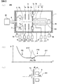
- FIG. 1 is a schematic diagram showing a configuration of a quadrupole mass spectrometer according to the first embodiment.
- FIG. 1A is a side cross-sectional view of the quadrupole mass spectrometer
- FIG. 1C is a graph showing a potential on a central axis AX in the device shown in FIG. 1A
- FIG. 1C is an enlarged view of a part of the device shown in FIG.
- FIG. 2 is a schematic diagram showing a configuration of a quadrupole mass spectrometer according to a modified example.
- FIG. 2A is a side sectional view of the quadrupole mass spectrometer
- FIG. 2B is FIG.
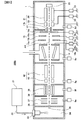
- FIG. 3 is a schematic diagram illustrating a configuration of a quadrupole mass spectrometer according to a second embodiment.
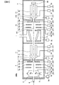
- FIG. 4 is a schematic diagram illustrating a configuration of a quadrupole mass spectrometer according to a third embodiment.
- the “potential” is an electric potential acting on an ion having a charge, and is the same as an electric potential for an ion having a positive charge. On the other hand, it represents the amount of the opposite sign to the potential.
- FIG. 1 is a schematic diagram illustrating a configuration of a quadrupole mass spectrometer 100 according to the first embodiment.
- FIG. 1A is a side sectional view of the quadrupole mass spectrometer 100
- FIG. 1B is a graph showing the potential on the central axis AX in the quadrupole mass spectrometer 100.
- 1) shows an enlarged view of a part of the device shown in FIG.
- an ionization chamber 2 an ion optical system 5, a partition 7, a quadrupole mass filter 11, and an ion detector 25 are provided inside a vacuum vessel 1 along a central axis AX. I have.
- a gas chromatograph device 30 is provided in front of the quadrupole mass spectrometer 100, and the sample gas flowing out of the gas chromatograph device 30 is supplied into the ionization chamber 2 via the connection pipe 4. .
- the ionization chamber 2 is an example of a gas sample ionization apparatus that ionizes an analysis target carried by a carrier gas by an electron impact method.
- the thermoelectrons generated in the filament 3 are accelerated, and the sample molecules are ionized by contacting the thermoelectrons with the sample molecules (or atoms) introduced into the ionization chamber 2.
- the generated ions are extracted from the ionization chamber 2 by the potential difference applied between the ionization chamber 2 and the ion optical system 5 and enter the ion optical system 5.
- the ions are converged by the ion optical system 5 and enter the pre-rod 9.
- the ion optical system 5 is, for example, an electrostatic lens including three electrodes of an incident-side electrode 5a, a middle-stage electrode 5b, and an emission-side electrode 5c.
- the quadrupole mass filter 11 includes a pre-rod 9 and a main rod 10 each having four rod electrodes, and an AC voltage is superimposed on the pre-rod 9 from a power supply 12, and a DC and an AC are superimposed on the main rod 10 from a power supply 13. The applied voltage is applied.
- the ion axis of the quadrupole mass filter 11 coincides with the optical axis of the ion optical system 5, and both axes are collectively referred to as a central axis AX.
- the partition wall 7 is a partition wall in the vacuum vessel 1 that separates a space in which the ion optical systems 5 having different required degrees of vacuum are arranged and a space in which the quadrupole mass filter 11 is arranged.
- An ion passage hole 7h through which ions pass is formed in a portion corresponding to the center axis AX of the partition wall 7 and its vicinity.
- the substantially cylindrical projection 5d which is a portion near the central axis AX, of the emission-side electrode 5c of the ion optical system 5 has the center of the ion optical system 5 inside the ion passage hole 7h. It is arranged so as to surround the axis AX and not contact the partition wall 7. Both spaces in the vacuum vessel 1 partitioned by the partition 7 are evacuated by vacuum pumps 8a and 8b, respectively.
- the vacuum vessel 1 is maintained at a ground potential so as to be easily handled. Therefore, the partition 7 attached to the inner wall of the vacuum vessel 1 is also kept at the ground potential. Also, a predetermined voltage is applied to the outlet side 2e of the ionization chamber 2 by the power supply 6s.
- FIG. 1B is a graph showing the potential ⁇ 1 on the central axis AX in the quadrupole mass spectrometer 100, that is, the voltage applied to each electrode 5 a to 5 c of the ion optical system 5 and the voltage applied to the prerod 9.
- the applied voltage represents a potential ⁇ 1 formed on the central axis AX.
- the potential ⁇ 1 has the same meaning as the potential, and when the analysis target is the anion, the potential ⁇ 1 has the opposite sign to the potential.
- the potential of the emission-side electrode 5c of the ion optical system 5 is set lower than the potentials of the ionization chamber 2 and the pre-rod 9 of the quadrupole mass filter 11.
- the potential ⁇ 1 on the central axis AX decreases from the exit (position P2) of the ionization chamber 2 toward the incident side end (position P5c) of the emission-side electrode 5c of the ion optical system 5.
- the projection 5d of the emission side electrode 5c surrounds the center axis AX.
- Potential ⁇ 1 has a substantially constant value.
- the potential ⁇ 1 on the central axis AX is increased by the voltage applied to the pre-rod 9 after the incident surface (position P9) of the pre-rod 9. After the incident surface (position P10) of the main rod 10, the value becomes substantially constant.
- the ions that have exited the ionization chamber 2 are accelerated by the inclination of the potential ⁇ 1 in the path to the emission-side electrode 5c (position P5c) of the ion optical system 5, and then pass through the inside of the protrusion 5d without being decelerated. I do. Then, the light enters the pre-rod 9 and is decelerated by the voltage applied to the pre-rod 9.
- the ions after being accelerated by the ion optical system 5, the ions are incident on the pre-rod 9 with almost no deceleration. Therefore, the speed of the ion beam at the time when the ion beam is incident on the pre-rod 9 can be increased, whereby the divergence angle of the ion beam can be reduced.
- the emittance of the ion beam at the time when the ion beam is incident on the prerod 9 can be brought close to the range of the acceptance of the prerod 9. Therefore, in the first embodiment, the ion beam can be efficiently introduced into the pre-rod 9.
- a potential ⁇ 11 indicated by a broken line in FIG. 1B indicates a potential on the central axis AX in a conventional general ion optical system for comparison.
- the partition wall 7 having the ion passage hole 7h for shielding the space in which the ion optical system 5 and the quadrupole mass filter 11 are arranged is used as the emission side electrode of the ion optical system 5. It was a target. However, in this case, since the partition wall 7 is maintained at the ground potential as described above, a large potential barrier is generated by the partition wall 7 immediately before the pre-rod 9 as shown by the potential ⁇ 11.
- the ion beam is greatly decelerated by the barrier (potential ⁇ 11) by the partition wall 7 and enters the pre-rod 9 at a large divergence angle.
- the barrier potential ⁇ 11
- the partition wall 7 the partition wall 7 and enters the pre-rod 9 at a large divergence angle.
- the cylindrical protrusion 5d which is a part of the emission-side electrode 5c of the ion optical system 5, is provided inside the ion passage hole 7h formed in the partition 7 with the partition 7.
- the partition wall 7 which is the ground potential is shielded by the projection 5d and does not adversely affect the potential on the central axis AX and the vicinity thereof. Does not slow down ions.
- the ion beam can be incident on the pre-rod 9 while maintaining a preferable emittance, and the ion beam can be efficiently introduced into the pre-rod 9.
- FIG. 1C is an enlarged view of the injection electrode 5C and the prerod 9 of the quadrupole mass spectrometer 100 shown in FIG.
- the positional relationship between the emission-side electrode 5c of the ion optical system 5, the pre-rod 9, and the central axis AX is as follows. It is preferable to satisfy the following conditions.
- the distance d1 between the central axis AX and the emission-side electrode 5C (the protrusion 5d) in the direction perpendicular to the central axis AX is preferably equal to or less than half the distance d2 between the central axis AX and the pre-rod 9. Further, it is preferable that the distance d3 between the emission-side electrode 5c (projection 5d) and the pre-rod 9 in the central axis AX direction is not more than half of the length d4 of the pre-rod 9 in the central axis AX direction.
- the interval is a distance from the end to the end.
- the interval d3 between the emission-side electrode 5c (projection 5d) and the pre-rod 9 is a distance from the right end of the projection 5d to the left end of the pre-rod 9. It is.
- the protrusion 5d is a substantially cylindrical member arranged so as to surround the center axis AX as described above, the protrusion 5d is perpendicular to the center axis AX between the center axis AX and the emission-side electrode 5C (projection 5d).
- the interval d1 in the direction is equal to half the inner diameter of the protrusion 5d.
- FIG. 2A is a schematic diagram illustrating a configuration of a quadrupole mass spectrometer 100a according to a modification.
- the configuration of the quadrupole mass spectrometer 100a of the modified example is almost the same as that of the quadrupole mass spectrometer 100 of the first embodiment. Therefore, the same reference numerals are given to the common portions, and the description will be appropriately omitted.
- the emission side electrode 5e of the ion optical system 5 is formed by the partition 7a, the space in the vacuum vessel 1 where the ion optical system 5 is arranged, and the quadrupole mass filter 11. It forms part of a partition that partitions the space in which it is placed.
- the partition 7a is set to the ground potential. Therefore, in this modification, an airtight insulating member 7b made of ceramic or the like is provided between the emission side electrode 5e of the ion optical system 5 and the partition 7a, and the emission side electrode 5e and the partition 7a are electrically insulated. are doing.
- a potential lower than the potential applied from the power source 6s to the outlet of the ionization chamber 2 and the potential lower than the potential applied from the power source 12 to the pre-rod 9 are applied from the power source 6c to the emission-side electrode 5e. Then, there is no structure that decelerates ions and has a higher potential than the emission-side electrode 5e between the emission-side electrode 5e and the pre-rod 9.
- FIG. 2B is a graph showing the potential ⁇ 2 on the central axis AX in the quadrupole mass spectrometer 100a of the modification.
- the potential ⁇ 2 on the central axis AX decreases from the outlet of the ionization chamber 2 (position P2) toward the emission-side electrode 5e of the ion optical system 5 (position P5e).
- the potential ⁇ 2 on the central axis AX is increased by the voltage applied to the pre-rod 9 after the incident surface (position P9) of the pre-rod 9. After the incident surface (position P10) of the main rod 10, the value becomes substantially constant.
- the ions exiting the ionization chamber 2 are accelerated by the inclination of the potential ⁇ 2 in the path to the emission-side electrode 5e (position P5e) of the ion optical system 5, and enter the pre-rod 9 with almost no deceleration. 9 is decelerated by the voltage applied to 9. Therefore, also in this modified example, the emittance of the ion beam at the time of incidence on the pre-rod 9 can be brought close to the range of the acceptance of the pre-rod 9, so that the ion beam can be efficiently introduced into the pre-rod 9. it can.
- the potential ⁇ 12 indicated by the broken line in FIG. 2B is, for comparison, the potential ⁇ 12 on the central axis AX when the emission-side electrode 5e is at the ground potential without the insulating member 7b as in the prior art. Represents. In this case, a large potential barrier is generated immediately before the pre-rod 9 by the emission-side electrode 5e which is the ground potential. Then, the ion beam is greatly decelerated at the emission-side electrode 5e, and enters the pre-rod 9 at a large divergence angle. As a result, most of the emittance of the ion beam that has passed through the conventional ion optical system does not fall within the acceptance range of the prerod 9, and the ratio of ions that cannot enter the prerod 9 increases.
- FIG. 2C is an enlarged view of a part of the exit-side electrode 5 e and the pre-rod 9 in the quadrupole mass spectrometer 100 a of the modification shown in FIG.
- the positional relationship between the emission-side electrode 5e of the ion optical system 5, the pre-rod 9, and the central axis AX is as follows. More preferably, the following conditions are satisfied.
- the distance d5 between the central axis AX and the emission-side electrode 5e in the direction perpendicular to the central axis AX is preferably equal to or less than half the distance d2 between the central axis AX and the pre-rod 9. Further, it is preferable that the distance d6 between the emission-side electrode 5e and the pre-rod 9 in the central axis AX direction is not more than half of the length d4 of the pre-rod 9 in the central axis AX direction.
- the gas sample ionization apparatus is not limited to the ionization chamber 2 employing the above-described electron impact method, but is an apparatus based on a chemical ionization method. May be used.
- an apparatus for ionizing a sample an apparatus for ionizing a liquid sample such as ESI, APCI, or APCI may be used instead of the ionization chamber 2 for ionizing a gas sample.
- the quadrupole mass spectrometers of the first embodiment and the modified example include a quadrupole mass filter 11 having a prerod 9, an ionization chamber 2, and ions generated in the ionization chamber 2
- the ion optical system 5 for guiding to the pre-rod 9 is provided, and the potentials of the emission-side electrodes 5c and 5e of the ion optical system 5 are lower than the potentials of the ionization chamber 2 and the pre-rod 9 of the quadrupole mass filter 11.
- the distances d1 and d4 between the central axis AX of the ion optical system 5 and the quadrupole mass filter 11 and the emission-side electrodes 5c and 5e are less than half the distance d2 between the central axis AX and the pre-rod 9.
- the distance d3, d5 between the emission-side electrodes 5c, 5e and the pre-rod 9 is less than half the length d4 of the pre-rod 9 in the central axis AX direction, so that ions are decelerated to the incidence surface of the pre-rod 9. Therefore, the ions can be made to be incident on the pre-rod 9, and the ions can be more efficiently introduced into the pre-rod 9.
- the ion optical system 5 and the quadrupole mass filter 11 are separated from each other, and the partition wall 7 having the ion passage hole 7h formed in the central axis AX of the ion optical system 5 is provided.
- At least a part (projection 5d) of the emission side electrode 5c is arranged so as to surround the central axis AX of the ion optical system 5 inside the ion passage hole 7h without contact with the partition wall 7.
- the influence of the ground potential applied to the partition wall 7 on the central axis AX is shielded by the projection 5d. For this reason, it is not necessary to provide an insulating mechanism in the partition 7, and cost reduction of the partition 7 and the whole apparatus can be achieved.
- the ionization chamber 2 a gas sample ionization chamber for ionizing an object to be analyzed carried by a carrier gas, efficient ionization of a gaseous sample supplied from the gas chromatograph device 30 can be achieved.
- a quadrupole mass spectrometer can be realized.
- FIG. 3 is a schematic diagram showing the configuration of the quadrupole mass spectrometer 100b of the second embodiment. Since many parts of the configuration of the quadrupole mass spectrometer 100b according to the second embodiment are common to the quadrupole mass spectrometer 100 according to the above-described first embodiment, the common parts are denoted by the same reference numerals. The description will be appropriately omitted.
- the configurations of the ion optical system 15 and the quadrupole mass filter 21 are the same as those of the ion optical system 5 and the quadrupole mass spectrometer 100 of the first embodiment, respectively.
- the configuration is the same as that of the quadrupole mass filter 11.
- the configurations of the power supplies 16a to 16c for supplying voltages to the ion optical system 15 and the quadrupole mass filter 21 and the power supplies 22 and 23 also correspond to the power supply 6a of the quadrupole mass spectrometer 100 of the first embodiment. 6c and power supplies 12 and 13.
- the partition wall 17 is a partition wall of the vacuum vessel 1 that separates a space in which the ion optical systems 15 having different required degrees of vacuum are arranged and a space in which the quadrupole mass filter 21 is arranged.
- an ion passage hole 17h through which ions pass is formed in the central axis AX of the partition wall 17 and a portion corresponding to the vicinity thereof.
- the substantially cylindrical projection 15d which is a portion of the emission-side electrode 15c of the ion optical system 15 near the central axis AX, is provided inside the ion passage hole 17h. It surrounds the central axis AX of the system 15 and is arranged in non-contact with the partition wall 17.
- the upstream quadrupole mass filter 42 and the CID (collision-induced dissociation) cell 14 are arranged upstream of the ion optical system 15, and a so-called triple quadrupole mass spectrometer 100b is provided. It is a quadrupole mass spectrometer. Therefore, the ions transported by the ion optical system 15 are mainly product ions generated in the CID cell 14.
- the liquid sample supplied from the liquid chromatograph device 31 is guided to the electrospray 33 by the introduction pipe 32.
- the electrospray 33 sprays the liquid sample into the liquid sample ionization chamber 34 together with a nebulizer gas such as nitrogen while applying a charge to the liquid sample.
- the sprayed liquid sample repeatedly evaporates and splits in the liquid sample ionization chamber 34 to become sample molecule ions.
- the ionization method of the analysis target in the liquid sample ionization chamber 34 is not limited to the ESI method (Electrospray ionization) using the electrospray 33 described above.
- the liquid sample may be ionized by an atmospheric pressure chemical ionization (APCI) or an atmospheric pressure photoionization source (APCI).
- APCI atmospheric pressure chemical ionization
- APCI atmospheric pressure photoionization source
- the CID cell 14 is also called a first ionization chamber
- the liquid sample ionization chamber 34 is also called a second ionization chamber.
- the quadrupole mass filter 11 is also called a first quadrupole mass filter
- the preceding quadrupole mass filter 42 is also called a second quadrupole mass filter.
- the ions generated in the liquid sample ionization chamber 34 enter the first intermediate vacuum chamber 36 through the heating capillary 35 having a small diameter. Then, the ions are guided to an ion guide 37 provided in the first intermediate vacuum chamber 36 and further enter the second intermediate vacuum chamber 38. An ion guide 39 is also provided in the second intermediate vacuum chamber 38, and the ions are guided by the ion guide 39 and enter a preceding quadrupole mass filter 42 including a pre-rod 40 and a main rod 41.
- the product ions generated in the CID cell 14 are extracted from the CID cell 14 by the potential difference applied between the CID cell 14 and the ion optical system 15 and enter the ion optical system 15.
- the product ions are converged by the ion optical system 15 and enter the pre-rod 19 of the quadrupole mass filter 21. Then, only ions having a predetermined mass-to-charge ratio pass through the main rod 20 of the quadrupole mass filter 21 and are detected by the ion detector 25.
- the optical axes of the ion guides 37 and 39 and the ion axis of the preceding quadrupole mass filter 42 coincide with the optical axis of the ion optical system 5 and the central axis AX which is the ion axis of the quadrupole mass filter 11. .
- the space in the vacuum vessel 1 in which the first intermediate vacuum chamber 36, the second intermediate vacuum chamber 38, and the preceding quadrupole mass filter 42 are installed is depressurized by vacuum pumps 8e, 8f, and 8g, respectively.
- the potential applied to the pre-rod 19 of the quadrupole mass filter 21 and the potential applied to the exit side of the CID cell 14 from the power supply 16s are applied to the emission-side electrode 15c of the ion optical system 15 as in the first embodiment. Is applied from the power supply 16c. Therefore, also in the second embodiment, the ions that have exited the CID cell 14 are accelerated by the ion optical system 15 and then enter the pre-rod 19 with little deceleration. Therefore, the speed of the ion beam at the time of incidence on the pre-rod 19 can be increased, and the divergence angle of the ion beam can be reduced. As a result, the emittance of the ion beam at the time of incidence on the pre-rod 19 can be brought close to the range of the acceptance of the pre-rod 19. Therefore, also in the second embodiment, ions can be efficiently introduced into the pre-rod 19.
- FIG. 4 is a schematic diagram illustrating a configuration of a quadrupole mass spectrometer 100c according to the third embodiment. Many parts of the configuration of the quadrupole mass spectrometer 100c of the third embodiment are different from the quadrupole mass spectrometer 100 of the first embodiment or the quadrupole mass spectrometer 100b of the second embodiment. Therefore, the common portions are denoted by the same reference numerals, and the description will be appropriately omitted.
- the quadrupole mass spectrometer 100c includes an ionization chamber 2, an ion optical system 5, a partition 7, a quadrupole mass filter 11, power supplies 6a to 6s, power supplies 12, 13, and vacuum pumps 8a and 8b.
- the configuration is the same as that of the above-described quadrupole mass spectrometer 100 of the first embodiment.
- the configurations of the CID cell 14, the ion optical system 15, the partition 17, the quadrupole mass filter 21, the power supplies 16a to 16s, the power supplies 22 and 23, and the vacuum pumps 8c and 8d are the same as those of the above-described second embodiment. It is the same as the polar mass spectrometer 100b.
- the gas chromatograph device 30 is not shown.
- the quadrupole mass spectrometer 100c of the third embodiment is a so-called triple quadrupole mass spectrometer, and the precursor ions generated in the ionization chamber 2 are guided to the quadrupole mass filter 11 by the ion optical system 5. I will Then, ions having a specific mass-to-charge ratio that have passed through the quadrupole mass filter 11 are incident on the CID cell 14 and product ions are generated in the CID cell 14. The product ions generated in the CID cell 14 are guided to the quadrupole mass filter 21 by the ion optical system 15, and only ions having a specific mass-to-charge ratio pass through the quadrupole mass filter 21 and are detected by the ion detector 25. Is detected.
- the CID cell 14 is also called a first ionization chamber, and the ionization chamber 2 is also called a second ionization chamber.
- the quadrupole mass filter 21 is also called a first quadrupole mass filter, and the quadrupole mass filter 11 is also called a second quadrupole mass filter.
- the ion optical system 15 is also called a first ion optical system, and the ion optical system 5 is also called a second ion optical system.
- the ion optical systems 5 and 15 have the emission-side electrode 5e via the insulating member 7b, similarly to the ion optical system 5 of the modified example shown in FIG. It may be configured to be held by the partition wall 7a. Further, in any of the embodiments and the modified examples, the ion optical systems 5 and 15 are not limited to the electrostatic lens including three electrodes, and may be an ion optical system including more electrodes.
- the CID cell 14 is used as the first ionization chamber in the configuration of the quadrupole mass spectrometer of the first embodiment or the modification.
- the ion optical system 15 guides the product ions generated in the CID cell 14 to the pre-rod 19 of the quadrupole mass filter 21.
- a second ionization chamber (liquid sample ionization chamber 34, ionization chamber 2) for generating precursor ions to be supplied to the CID cell 14, and a second quadrupole mass filter (previous stage quadrupole mass filter) for selecting precursor ions Filter 42, quadrupole mass filter 11) and second ion optical system (ion guides 37, 39, ion optical system 5) for guiding precursor ions generated in the second ionization chamber to the second quadrupole mass filter It has.
- the product ions generated in the CID cell 14 can be efficiently introduced into the quadrupole mass filter 21.
- the efficiency of ion incidence on the quadrupole mass filter 21 can be improved, and high sensitivity and high accuracy quadrupole mass spectrometers 100b and 100c can be realized.
- the second ionization chamber a liquid sample ionization chamber 34 for ionizing the analysis object carried by the carrier liquid, the efficiency of the liquid sample supplied from the liquid chromatograph apparatus 31 can be improved. Quadrupole mass spectrometer can be realized.
- the second quadrupole mass filter 11 has the pre-rod 9, and the potential of the emission-side electrode 5c of the second ion optical system (ion optical system 5) is equal to that of the second ionization chamber (ionization chamber 2).
- the quadrupole mass filter 11 By making the configuration lower than the potential of the pre-rod 9 of the second quadrupole mass filter (quadrupole mass filter 11), the quadrupole mass filter 11 on the front side and the rear side of the triple quadrupole mass spectrometer In both the quadrupole mass filters 21, the ion incidence efficiency can be improved.
- 100, 100a-c quadrupole mass spectrometer, 1: vacuum vessel, 2 ... gas sample ionization chamber (ionization chamber), 3 ... filament, 4 ... connecting pipe, 5, 15 ... ion optical system, 6a-6s, 16a to 16s power supply, 8a to 8g vacuum pump, 11, 21 quadrupole mass filter, 9, 19 pre rod, 10, 20 main rod, 25 ion detector, 14 CID cell, 30 gas chroma Tograph apparatus, 31: liquid chromatograph apparatus, 33: electrospray (ESI), 34: liquid sample ionization chamber (ionization chamber), 37, 39: ion guide, 42: preceding quadrupole mass filter
Landscapes
- Chemical & Material Sciences (AREA)
- Analytical Chemistry (AREA)
- Electron Tubes For Measurement (AREA)
- Other Investigation Or Analysis Of Materials By Electrical Means (AREA)
Abstract
四重極質量分析装置(100)は、プリロッドを有する四重極マスフィルタ(21)と、イオン化室(2)と、イオン化室(2)で生成されるイオンを四重極マスフィルタ(21)のプリロッド(9、19)に誘導するイオン光学系(5、15)を備え、イオン光学系(5、15)の射出側電極(5c)のポテンシャルは、イオン化室(2)および四重極マスフィルタ(21)のプリロッド(9、19)のポテンシャルよりも低く、射出側電極(5c)とプリロッド(9、19)との間には、イオンを減速させる、射出側電極(5c)よりも高いポテンシャルを有する構造物が存在しない。
Description
本発明は四重極質量分析装置に関する。
小型で感度および分析スループットに優れた質量分析装置として、四重極質量分析装置が広く利用されている。四重極質量分析装置は、中心軸を囲んで配置された四重極マスフィルタと呼ばれる4本のロッド電極(メインロッド)に直流電圧と交流電圧を印加して、所定のm/z(質量電荷比)のイオンのみを通過させるような振動電場を発生させることにより、質量分析を行う装置である。
高精度な分析を行うためには、分析対象のイオンを四重極マスフィルタに効率良く入射させる必要がある。そこで、イオン源であるイオン化室と四重極マスフィルタとの間に、静電レンズからなるイオン光学系を配置し、イオン化室で生成されたイオンをイオン光学系により収束させて四重極マスフィルタに導いている。
また、四重極マスフィルタのメインロッドの上流側に、プリロッドと呼ばれるロッド電極を配置するとともに、プリロッドから射出されるイオンビームのエミッタンスとメインロッドのアクセプタンスとをマッチングさせることにより、分析対象のイオンの四重極マスフィルタへの入射効率を向上させた四重極質量分析装置も提案されている(特許文献1参照)。
また、四重極マスフィルタのメインロッドの上流側に、プリロッドと呼ばれるロッド電極を配置するとともに、プリロッドから射出されるイオンビームのエミッタンスとメインロッドのアクセプタンスとをマッチングさせることにより、分析対象のイオンの四重極マスフィルタへの入射効率を向上させた四重極質量分析装置も提案されている(特許文献1参照)。
特許文献1の四重極質量分析装置においては、四重極マスフィルタへのイオンの入射効率は改善する。しかし、より高精度な分析のためには、特許文献1の四重極質量分析装置ではイオンの入射効率はまだ不十分であり、さらなる入射効率の改善が求められている。
本発明の第1の態様による四重極質量分析装置は、プリロッドを有する四重極マスフィルタと、イオン化室と、前記イオン化室で生成されるイオンを前記四重極マスフィルタの前記プリロッドに誘導するイオン光学系を備え、前記イオン光学系の射出側電極のポテンシャルは、前記イオン化室および前記四重極マスフィルタの前記プリロッドのポテンシャルよりも低く、前記射出側電極と前記プリロッドとの間には、前記イオンを減速させる、前記射出側電極よりも高いポテンシャルを有する構造物が存在しない。
本発明の第2の態様による四重極質量分析装置は、第1の態様による四重極質量分析装置において、前記イオン光学系および前記四重極マスフィルタの中心軸と前記射出側電極との間隔は、前記中心軸と前記プリロッドとの間隔の半分以下であり、前記射出側電極と前記プリロッドとの間隔は、前記プリロッドの前記中心軸方向の長さの半分以下であることが好ましい。
本発明の第3の態様による四重極質量分析装置は、第2の態様による四重極質量分析装置において、前記イオン光学系と前記四重極マスフィルタとを仕切り、前記イオン光学系の中心軸の部分にイオン通過孔が形成されている隔壁を備え、前記イオン光学系の前記射出側電極の少なくとも一部は、前記隔壁とは非接触に前記イオン通過孔の内部に、前記イオン光学系の中心軸を囲んで配置されていることが好ましい。
本発明の第4の態様による四重極質量分析装置は、第1から第3までのいずれかの態様による四重極質量分析装置において、前記イオン化室は、キャリアガスにより搬送される分析対象をイオン化するガス試料イオン化室であることが好ましい。
本発明の第5の態様による四重極質量分析装置は、第1から第3までのいずれかの態様による四重極質量分析装置において、前記イオン化室はCIDセルであり、前記イオン光学系は、前記CIDセルで生成されたプロダクトイオンを前記四重極マスフィルタの前記プリロッドに誘導するとともに、さらに、前記CIDセルに供給するプリカーサーイオンを生成する第2イオン化室と、前記プリカーサーイオンを選別する第2四重極マスフィルタと、前記第2イオン化室で生成される前記プリカーサーイオンを前記第2四重極マスフィルタに誘導する第2イオン光学系と、を備えることが好ましい。
本発明の第6の態様による四重極質量分析装置は、第5の態様による四重極質量分析装置において、前記第2イオン化室は、キャリア液体により搬送される分析対象をイオン化する液体試料イオン化室であることが好ましい。
本発明の第7の態様による四重極質量分析装置は、第5の態様による四重極質量分析装置において、前記第2四重極マスフィルタはプリロッドを有し、前記第2イオン光学系の射出側電極のポテンシャルは、前記第2イオン化室および前記第2四重極マスフィルタの前記プリロッドのポテンシャルよりも低いことが好ましい。
本発明の第8の態様による四重極質量分析装置は、第7の態様による四重極質量分析装置において、前記第2イオン化室は、キャリアガスにより搬送される分析対象をイオン化するガス試料イオン化室であることが好ましい。
本発明の第2の態様による四重極質量分析装置は、第1の態様による四重極質量分析装置において、前記イオン光学系および前記四重極マスフィルタの中心軸と前記射出側電極との間隔は、前記中心軸と前記プリロッドとの間隔の半分以下であり、前記射出側電極と前記プリロッドとの間隔は、前記プリロッドの前記中心軸方向の長さの半分以下であることが好ましい。
本発明の第3の態様による四重極質量分析装置は、第2の態様による四重極質量分析装置において、前記イオン光学系と前記四重極マスフィルタとを仕切り、前記イオン光学系の中心軸の部分にイオン通過孔が形成されている隔壁を備え、前記イオン光学系の前記射出側電極の少なくとも一部は、前記隔壁とは非接触に前記イオン通過孔の内部に、前記イオン光学系の中心軸を囲んで配置されていることが好ましい。
本発明の第4の態様による四重極質量分析装置は、第1から第3までのいずれかの態様による四重極質量分析装置において、前記イオン化室は、キャリアガスにより搬送される分析対象をイオン化するガス試料イオン化室であることが好ましい。
本発明の第5の態様による四重極質量分析装置は、第1から第3までのいずれかの態様による四重極質量分析装置において、前記イオン化室はCIDセルであり、前記イオン光学系は、前記CIDセルで生成されたプロダクトイオンを前記四重極マスフィルタの前記プリロッドに誘導するとともに、さらに、前記CIDセルに供給するプリカーサーイオンを生成する第2イオン化室と、前記プリカーサーイオンを選別する第2四重極マスフィルタと、前記第2イオン化室で生成される前記プリカーサーイオンを前記第2四重極マスフィルタに誘導する第2イオン光学系と、を備えることが好ましい。
本発明の第6の態様による四重極質量分析装置は、第5の態様による四重極質量分析装置において、前記第2イオン化室は、キャリア液体により搬送される分析対象をイオン化する液体試料イオン化室であることが好ましい。
本発明の第7の態様による四重極質量分析装置は、第5の態様による四重極質量分析装置において、前記第2四重極マスフィルタはプリロッドを有し、前記第2イオン光学系の射出側電極のポテンシャルは、前記第2イオン化室および前記第2四重極マスフィルタの前記プリロッドのポテンシャルよりも低いことが好ましい。
本発明の第8の態様による四重極質量分析装置は、第7の態様による四重極質量分析装置において、前記第2イオン化室は、キャリアガスにより搬送される分析対象をイオン化するガス試料イオン化室であることが好ましい。
本発明によれば、四重極マスフィルタへのイオンの入射効率を改善し、高感度および高精度の四重極質量分析装置を実現できる。
本明細書において、「ポテンシャル」とは、電荷を有するイオンに対して作用する電気的なポテンシャルであり、正の電荷を持つイオンに対しては電位と同義であり、負の電荷を持つイオンに対しては電位とは逆符号の量を表す。
(第1実施形態の四重極質量分析装置)
図1は、第1実施形態の四重極質量分析装置100の構成を示す概略図である。図1(a)は四重極質量分析装置100の側断面図を表し、図1(b)は四重極質量分析装置100における中心軸AX上のポテンシャルを表わすグラフであり、図1(c)は図1(a)に示した装置の一部分の拡大図を表す。
四重極質量分析装置100においては、真空容器1の内部にイオン化室2、イオン光学系5、隔壁7、四重極マスフィルタ11、及びイオン検出器25が中心軸AXに沿って設けられている。
図1は、第1実施形態の四重極質量分析装置100の構成を示す概略図である。図1(a)は四重極質量分析装置100の側断面図を表し、図1(b)は四重極質量分析装置100における中心軸AX上のポテンシャルを表わすグラフであり、図1(c)は図1(a)に示した装置の一部分の拡大図を表す。
四重極質量分析装置100においては、真空容器1の内部にイオン化室2、イオン光学系5、隔壁7、四重極マスフィルタ11、及びイオン検出器25が中心軸AXに沿って設けられている。
この四重極質量分析装置100の前段には、ガスクロマトグラフ装置30が設けられており、ガスクロマトグラフ装置30から流出する試料ガスが、接続管4を経由してイオン化室2内へと供給される。イオン化室2はキャリアガスにより搬送される分析対象を電子衝撃法によりイオン化するガス試料イオン化装置の一例である。フィラメント3で発生した熱電子が加速され、イオン化室2に導入された試料分子(又は原子)にこの熱電子が接触することによって試料分子はイオン化される。
発生したイオンは、イオン化室2とイオン光学系5の間に印加された電位差によりイオン化室2から引き出されてイオン光学系5に入射する。そしてイオンは、イオン光学系5により収束されて、プリロッド9に入射する。
イオン光学系5は、一例として入射側電極5a、中段電極5b、射出側電極5cの3つの電極からなる静電レンズである。
イオン光学系5は、一例として入射側電極5a、中段電極5b、射出側電極5cの3つの電極からなる静電レンズである。
四重極マスフィルタ11は、それぞれ4本のロッド電極からなるプリロッド9とメインロッド10とを含み、プリロッド9には電源12から交流電圧が、メインロッド10には電源13から直流と交流が重畳された電圧が印加される。四重極マスフィルタ11のイオン軸はイオン光学系5の光軸と一致しており、両軸を併せて中心軸AXと呼ぶ。
隔壁7は、真空容器1の内部のうち、要求される真空度の異なるイオン光学系5が配置される空間と四重極マスフィルタ11が配置される空間とを仕切る隔壁である。隔壁7の中心軸AXおよびその近傍に相当する部分には、イオンが通過するためのイオン通過孔7hが形成されている。
本第1実施形態においては、イオン光学系5の射出側電極5cのうちの中心軸AXに近い部分である略円筒状の突起部5dは、イオン通過孔7hの内部にイオン光学系5の中心軸AXを囲んで、隔壁7とは非接触に配置されている。
隔壁7により仕切られた真空容器1内の両空間は、それぞれ真空ポンプ8a、8bにより排気されている。
本第1実施形態においては、イオン光学系5の射出側電極5cのうちの中心軸AXに近い部分である略円筒状の突起部5dは、イオン通過孔7hの内部にイオン光学系5の中心軸AXを囲んで、隔壁7とは非接触に配置されている。
隔壁7により仕切られた真空容器1内の両空間は、それぞれ真空ポンプ8a、8bにより排気されている。
イオン光学系5の各電極5a~5cには、電源6a~6cによりそれぞれ異なる電圧が印加されている。なお、一般に真空容器1は、取り扱いが容易なようにグランド電位に保たれている。従って、真空容器1の内壁に取り付けられている隔壁7も、グランド電位に保たれている。
また、イオン化室2の出口側2eにも、電源6sにより所定の電圧が印加されている。
また、イオン化室2の出口側2eにも、電源6sにより所定の電圧が印加されている。
図1(b)は、四重極質量分析装置100における中心軸AX上のポテンシャルφ1を表わすグラフであり、すなわち、イオン光学系5の各電極5a~5cに印加された電圧とプリロッド9に印加された電圧が中心軸AX上形成するポテンシャルφ1を表している。
上述のとおり、分析対象が陽イオンの場合にはポテンシャルφ1は電位と同義であり、分析対象が陰イオンの場合にはポテンシャルφ1は電位とは逆符号となる。
上述のとおり、分析対象が陽イオンの場合にはポテンシャルφ1は電位と同義であり、分析対象が陰イオンの場合にはポテンシャルφ1は電位とは逆符号となる。
本第1実施形態においては、イオン光学系5の射出側電極5cのポテンシャルを、イオン化室2および四重極マスフィルタ11のプリロッド9のポテンシャルよりも低く設定している。これにより、中心軸AX上のポテンシャルφ1は、イオン化室2の出口(位置P2)からイオン光学系5の射出側電極5cの入射側の端部(位置P5c)に向かって低下する。一方、射出側電極5cの入射側端部(位置P5c)から、突起部5dの射出側端部(位置P5d)の間は、中心軸AXの周囲を射出側電極5cの突起部5dが取り囲むため、ポテンシャルφ1はほぼ一定値となっている。中心軸AX上のポテンシャルφ1は、プリロッド9の入射面(位置P9)以降では、プリロッド9に印加されている電圧により上昇する。そして、メインロッド10の入射面(位置P10)以降は、ほぼ一定値となる。
従って、イオン化室2を出たイオンは、イオン光学系5の射出側電極5c(位置P5c)までの経路においてポテンシャルφ1の傾斜により加速され、その後、減速されることなく突起部5dの内部を通過する。そして、プリロッド9に入射し、プリロッド9に印加されている電圧により減速される。
本第1実施形態においては、イオンは、イオン光学系5により加速された後、ほとんど減速されることなくプリロッド9に入射する。従って、プリロッド9に入射する時点でのイオンビームの速度を速め、これによりイオンビームの発散角を小さくすることができる。この結果、プリロッド9に入射する時点でのイオンビームのエミッタンスを、プリロッド9のアクセプタンスの範囲内に近づけることができる。このため、本第1実施形態では、イオンビームを効率良くプリロッド9内に導入することができる。
本第1実施形態においては、イオンは、イオン光学系5により加速された後、ほとんど減速されることなくプリロッド9に入射する。従って、プリロッド9に入射する時点でのイオンビームの速度を速め、これによりイオンビームの発散角を小さくすることができる。この結果、プリロッド9に入射する時点でのイオンビームのエミッタンスを、プリロッド9のアクセプタンスの範囲内に近づけることができる。このため、本第1実施形態では、イオンビームを効率良くプリロッド9内に導入することができる。
図1(b)中に破線で示したポテンシャルφ11は、比較のために、従来の一般的なイオン光学系における中心軸AX上のポテンシャルを示す。従来においては、イオン光学系5と四重極マスフィルタ11がそれぞれ配置される空間を遮蔽するためのイオン通過孔7hを有する隔壁7自体を、イオン光学系5の射出側電極とすることが一般的であった。
しかしこの場合、隔壁7は上述のとおりグランド電位に保たれているため、ポテンシャルφ11に示したとおり、プリロッド9の直前に隔壁7による大きなポテンシャル障壁が生じる。そして、イオンビームは隔壁7による障壁(ポテンシャルφ11)により大きく減速され、大きな発散角でプリロッド9に入射することとなる。その結果、従来のイオン光学系を通過したイオンビームのエミッタンスは、その大部分がプリロッド9のアクセプタンスの範囲内に収まらず、プリロッド9に進入できないイオンの比率が高くなってしまう。
しかしこの場合、隔壁7は上述のとおりグランド電位に保たれているため、ポテンシャルφ11に示したとおり、プリロッド9の直前に隔壁7による大きなポテンシャル障壁が生じる。そして、イオンビームは隔壁7による障壁(ポテンシャルφ11)により大きく減速され、大きな発散角でプリロッド9に入射することとなる。その結果、従来のイオン光学系を通過したイオンビームのエミッタンスは、その大部分がプリロッド9のアクセプタンスの範囲内に収まらず、プリロッド9に進入できないイオンの比率が高くなってしまう。
本第1実施形態においては、上述のとおりイオン光学系5の射出側電極5cの一部である筒状の突起部5dは、隔壁7に形成されているイオン通過孔7hの内部に、隔壁7とは非接触に、中心軸AXを囲んで配置されている。このため、グランド電位である隔壁7が形成する電場は、突起部5dに遮蔽され、中心軸AX上およびその近傍のポテンシャルに悪影響を及ぼすことがなく、射出側電極5cとプリロッド9との間においてイオンを減速させることがない。また、隔壁7以外にも、射出側電極5cとプリロッド9との間には、イオンを減速させる、射出側電極5cよりも高いポテンシャルを有する構造物が存在しない。すなわち、射出側電極5cよりも高いポテンシャルを有する構造物であって、射出側電極5cとプリロッド9との間のイオンの経路上にイオンを減速させるポテンシャルを形成する構造物が存在しない。従って、本第1実施形態においては、好ましいエミッタンスを保ってイオンビームをプリロッド9に入射させることができ、イオンビームを効率良くプリロッド9内に導入することができる。
図1(c)は図1(a)に示した四重極質量分析装置100のうちの射出側電極5C、およびプリロッド9の部分の拡大図を示している。
イオンを、プリロッド9の入射面(位置P9)まで減速させず、プリロッド9の内部で減速させるためには、イオン光学系5の射出側電極5c、プリロッド9、および中心軸AXの位置関係が、以下の条件を満たすことが好ましい。
すなわち、中心軸AXと射出側電極5C(突起部5d)との中心軸AXに垂直な方向の間隔d1は、中心軸AXとプリロッド9との間隔d2の半分以下であることが好ましい。また、射出側電極5c(突起部5d)とプリロッド9との中心軸AX方向の間隔d3は、プリロッド9の中心軸AX方向の長さd4の半分以下であることが好ましい。
イオンを、プリロッド9の入射面(位置P9)まで減速させず、プリロッド9の内部で減速させるためには、イオン光学系5の射出側電極5c、プリロッド9、および中心軸AXの位置関係が、以下の条件を満たすことが好ましい。
すなわち、中心軸AXと射出側電極5C(突起部5d)との中心軸AXに垂直な方向の間隔d1は、中心軸AXとプリロッド9との間隔d2の半分以下であることが好ましい。また、射出側電極5c(突起部5d)とプリロッド9との中心軸AX方向の間隔d3は、プリロッド9の中心軸AX方向の長さd4の半分以下であることが好ましい。
ここで間隔とは端部から端部までの距離であり、例えば、射出側電極5c(突起部5d)とプリロッド9との間隔d3とは、突起部5dの右端からプリロッド9の左端までの距離である。また、突起部5dは、上述のように中心軸AXを囲んで配置される略円筒状の部材であるので、中心軸AXと射出側電極5C(突起部5d)との中心軸AXに垂直な方向の間隔d1は、突起部5dの内径の半分に等しい。
上記の位置関係の条件を満たすことにより、プリロッド9の入射面(位置P9)と突起部5dの射出端(位置P5d)でのポテンシャルφ1をほぼ等しくすることができる。この結果、イオンをプリロッド9の入射面まで減速させずにプリロッド9に入射させることができ、より効率良くイオンをプリロッド9に導入することができる。
(四重極質量分析装置の変形例)
図2(a)は、変形例の四重極質量分析装置100aの構成を示す概略図である。変形例の四重極質量分析装置100aの構成は、大部分が上述の第1実施形態の四重極質量分析装置100と共通している。そのため、共通部分には、同一の符号を付して、適宜説明を省略する。
図2(a)は、変形例の四重極質量分析装置100aの構成を示す概略図である。変形例の四重極質量分析装置100aの構成は、大部分が上述の第1実施形態の四重極質量分析装置100と共通している。そのため、共通部分には、同一の符号を付して、適宜説明を省略する。
変形例の四重極質量分析装置100aにおいては、イオン光学系5の射出側電極5eは、隔壁7aとともに、真空容器1内のイオン光学系5が配置される空間と四重極マスフィルタ11が配置される空間を仕切る隔壁の一部をなしている。ただし、上述のように、真空容器1は通常グランド電位に設定されるので、隔壁7aはグランド電位に設定されてしまう。そこで、本変形例においては、イオン光学系5の射出側電極5eと隔壁7aとの間にセラミック等からなる気密性の絶縁部材7bを設け、射出側電極5eと隔壁7aとを電気的に絶縁している。そして、電源6sからイオン化室2の出口に印加されるポテンシャルおよび電源12からプリロッド9に印加されるポテンシャルよりも低いポテンシャルが、電源6cから射出側電極5eに印加されている。そして、射出側電極5eとプリロッド9との間には、イオンを減速させる、射出側電極5eよりも高いポテンシャルを有する構造物が存在しない。
図2(b)は変形例の四重極質量分析装置100aにおける中心軸AX上のポテンシャルφ2を表わすグラフである。本変形例においても、中心軸AX上のポテンシャルφ2は、イオン化室2の出口(位置P2)からイオン光学系5の射出側電極5e(位置P5e)に向かって低下する。中心軸AX上のポテンシャルφ2は、プリロッド9の入射面(位置P9)以降では、プリロッド9に印加されている電圧により上昇する。そして、メインロッド10の入射面(位置P10)以降は、ほぼ一定値となる。
このため、イオン化室2を出たイオンは、イオン光学系5の射出側電極5e(位置P5e)までの経路においてポテンシャルφ2の傾斜により加速され、ほとんど減速されることなくプリロッド9に入射し、プリロッド9に印加されている電圧により減速される。
従って、本変形例においてもプリロッド9に入射する時点でのイオンビームのエミッタンスを、プリロッド9のアクセプタンスの範囲内に近づけることができ、このため、イオンビームを効率良くプリロッド9内に導入することができる。
従って、本変形例においてもプリロッド9に入射する時点でのイオンビームのエミッタンスを、プリロッド9のアクセプタンスの範囲内に近づけることができ、このため、イオンビームを効率良くプリロッド9内に導入することができる。
図2(b)中に破線で示したポテンシャルφ12は、比較のために、従来のとおり絶縁部材7bを設けず、従って射出側電極5eがグランド電位である場合の中心軸AX上のポテンシャルφ12を表している。この場合には、プリロッド9の直前にグランド電位である射出側電極5eによる大きなポテンシャル障壁が生じる。そして、イオンビームは射出側電極5eにおいて大きく減速され、大きな発散角でプリロッド9に入射することとなる。その結果、従来のイオン光学系を通過したイオンビームのエミッタンスは、その大部分がプリロッド9のアクセプタンスの範囲内に収まらず、プリロッド9に進入できないイオンの比率が高くなってしまう。
図2(c)は図2(a)に示した変形例の四重極質量分析装置100aのうちの射出側電極5eおよびプリロッド9の部分の拡大図を示している。
イオンを、プリロッド9の入射面(位置P9)まで減速させず、プリロッド9の内部で減速させるためには、イオン光学系5の射出側電極5e、プリロッド9、および中心軸AXの位置関係が、以下の条件を満たすことがさらに好ましい。
すなわち、中心軸AXと射出側電極5eとの中心軸AXに垂直な方向の間隔d5は、中心軸AXとプリロッド9との間隔d2の半分以下であることが好ましい。また、射出側電極5eとプリロッド9との中心軸AX方向の間隔d6は、プリロッド9の中心軸AX方向の長さd4の半分以下であることが好ましい。
イオンを、プリロッド9の入射面(位置P9)まで減速させず、プリロッド9の内部で減速させるためには、イオン光学系5の射出側電極5e、プリロッド9、および中心軸AXの位置関係が、以下の条件を満たすことがさらに好ましい。
すなわち、中心軸AXと射出側電極5eとの中心軸AXに垂直な方向の間隔d5は、中心軸AXとプリロッド9との間隔d2の半分以下であることが好ましい。また、射出側電極5eとプリロッド9との中心軸AX方向の間隔d6は、プリロッド9の中心軸AX方向の長さd4の半分以下であることが好ましい。
上記の位置関係の条件を満たすことにより、プリロッド9の入射面(位置P9)と射出側電極5e(位置P5e)でのポテンシャルφ2をほぼ等しくすることができる。この結果、イオンをプリロッド9の入射面まで減速させずにプリロッド9に入射させることができ、より効率良くイオンをプリロッド9に導入することができる。
上述の第1実施形態および変形例の四重極質量分析装置100、100aにおいて、ガス試料イオン化装置は、上述の電子衝撃法を採用したイオン化室2に限られるわけではなく、化学イオン化法による装置を用いても良い。
また、試料をイオン化する装置として、ガス試料をイオン化するイオン化室2ではなく、ESI、APCI、APCI等の液体試料をイオン化する装置を使用することもできる。
また、試料をイオン化する装置として、ガス試料をイオン化するイオン化室2ではなく、ESI、APCI、APCI等の液体試料をイオン化する装置を使用することもできる。
(第1実施形態および変形例の効果)
上述の第1実施形態および変形例によれば、次の作用効果が得られる。
(1)第1実施形態および変形例の四重極質量分析装置は、プリロッド9を有する四重極マスフィルタ11と、イオン化室2と、イオン化室2で生成されるイオンを四重極マスフィルタ11のプリロッド9に誘導するイオン光学系5を備え、イオン光学系5の射出側電極5c、5eのポテンシャルはイオン化室2および四重極マスフィルタ11のプリロッド9のポテンシャルよりも低く、射出側電極5c、5eとプリロッド9との間には、イオンを減速させる、射出側電極5c、5eよりも高いポテンシャルを有する構造物が存在しない構成を有している。
この構成により、イオンは、イオン光学系5により加速された後、ほとんど減速されることなくプリロッド9に入射する。すなわち、プリロッド9に入射するイオンビームの速度を速め、イオンビームの発散角を小さくすることができる。これにより、プリロッド9に入射する時点でのイオンビームのエミッタンスを、プリロッド9のアクセプタンスの範囲内に近づけることができ、イオンを効率良くプリロッド9内に導入することができる。その結果、四重極マスフィルタ11へのイオンの入射効率を改善し、高感度および高精度の四重極質量分析装置100、100aを実現できる。
上述の第1実施形態および変形例によれば、次の作用効果が得られる。
(1)第1実施形態および変形例の四重極質量分析装置は、プリロッド9を有する四重極マスフィルタ11と、イオン化室2と、イオン化室2で生成されるイオンを四重極マスフィルタ11のプリロッド9に誘導するイオン光学系5を備え、イオン光学系5の射出側電極5c、5eのポテンシャルはイオン化室2および四重極マスフィルタ11のプリロッド9のポテンシャルよりも低く、射出側電極5c、5eとプリロッド9との間には、イオンを減速させる、射出側電極5c、5eよりも高いポテンシャルを有する構造物が存在しない構成を有している。
この構成により、イオンは、イオン光学系5により加速された後、ほとんど減速されることなくプリロッド9に入射する。すなわち、プリロッド9に入射するイオンビームの速度を速め、イオンビームの発散角を小さくすることができる。これにより、プリロッド9に入射する時点でのイオンビームのエミッタンスを、プリロッド9のアクセプタンスの範囲内に近づけることができ、イオンを効率良くプリロッド9内に導入することができる。その結果、四重極マスフィルタ11へのイオンの入射効率を改善し、高感度および高精度の四重極質量分析装置100、100aを実現できる。
(2)さらに、イオン光学系5および四重極マスフィルタ11の中心軸AXと射出側電極5c、5eとの間隔d1、d4は、中心軸AXとプリロッド9との間隔d2の半分以下であり、射出側電極5c,5eとプリロッド9との間隔d3、d5は、プリロッド9の中心軸AX方向の長さd4の半分以下である構成とすることで、イオンをプリロッド9の入射面まで減速させずにプリロッド9に入射させることができ、より効率良くイオンをプリロッド9に導入することができる。
(3)さらに、イオン光学系5と四重極マスフィルタ11とを仕切り、イオン光学系5の中心軸AXの部分にイオン通過孔7hが形成されている隔壁7を備え、イオン光学系5の射出側電極5cの少なくとも一部(突起部5d)は、隔壁7とは非接触にイオン通過孔7hの内部に、イオン光学系5の中心軸AXを囲んで配置されている構成とすることで、隔壁7に印加されているグランド電位が中心軸AXに及ぼす影響が、突起部5dにより遮蔽される。このため、隔壁7に絶縁機構を設ける必要がなく、隔壁7および装置全体の低コスト化が図れる。
(4)さらに、イオン化室2を、キャリアガスにより搬送される分析対象をイオン化するガス試料イオン化室とすることで、ガスクロマトグラフ装置30から供給されるガス状の試料に対して、効率の良い四重極質量分析装置を実現できる。
(4)さらに、イオン化室2を、キャリアガスにより搬送される分析対象をイオン化するガス試料イオン化室とすることで、ガスクロマトグラフ装置30から供給されるガス状の試料に対して、効率の良い四重極質量分析装置を実現できる。
(第2実施形態の四重極質量分析装置)
図3は、第2実施形態の四重極質量分析装置100bの構成を示す概略図である。
第2実施形態の四重極質量分析装置100bの構成のうちの多くの部分は、上述の第1実施形態の四重極質量分析装置100と共通するので、共通部分には同一の符号を付して説明を適宜省略する。
図3は、第2実施形態の四重極質量分析装置100bの構成を示す概略図である。
第2実施形態の四重極質量分析装置100bの構成のうちの多くの部分は、上述の第1実施形態の四重極質量分析装置100と共通するので、共通部分には同一の符号を付して説明を適宜省略する。
第2実施形態の四重極質量分析装置100bにおいて、イオン光学系15、四重極マスフィルタ21の構成は、それぞれ上述の第1実施形態の四重極質量分析装置100のイオン光学系5、四重極マスフィルタ11の構成と同一である。また、イオン光学系15、四重極マスフィルタ21にそれぞれ電圧を供給する電源16a~16cおよび電源22、23の構成も、それぞれ上述の第1実施形態の四重極質量分析装置100の電源6a~6cおよび電源12、13と同一である。
隔壁17は、真空容器1のうち、要求される真空度の異なるイオン光学系15が配置される空間と四重極マスフィルタ21が配置される空間とを仕切る隔壁である。上述の第1実施形態の隔壁7と同様に、隔壁17の中心軸AXおよびその近傍に相当する部分には、イオンが通過するためのイオン通過孔17hが形成されている。そして、上述の第1実施形態と同様に、イオン光学系15の射出側電極15cのうちの中心軸AXに近い部分である略円筒状の突起部15dは、イオン通過孔17hの内部にイオン光学系15の中心軸AXを囲んで、隔壁17とは非接触に配置されている。
第2実施形態の四重極質量分析装置100bにおいては、イオン光学系15よりも上流側に、前段の四重極マスフィルタ42およびCID(collision-induced dissociation)セル14が配置され、いわゆるトリプル四重極質量分析装置となっている。従って、イオン光学系15が輸送するイオンは、主にCIDセル14内で生成されたプロダクトイオンである。
液体クロマトグラフ装置31から供給される液体状の試料は、導入配管32によりエレクトロスプレー33に導かれる。エレクトロスプレー33は、液体状の試料に電荷を付与しながら窒素等のネブライザーガスと共に液体試料イオン化室34内に噴霧する。噴霧された液体状の試料は、液体試料イオン化室34内で蒸発と分裂を繰り返して試料分子のイオンとなる。
なお、液体試料イオン化室34での分析対象のイオン化方法は、上述のエレクトロスプレー33を用いたESI法(Electrospray ionization)に限られるわけではない。例えば、大気圧化学イオン化法(Atmospheric pressure chemical ionization,APCI)や大気圧光イオン化法(Atmospheric Pressure Photoionization Source,APCI)により液体試料をイオン化しても良い。
なお、本第2実施形態においては、CIDセル14を第1イオン化室とも呼び、液体試料イオン化室34を第2イオン化室とも呼ぶ。四重極マスフィルタ11を第1四重極マスフィルタと、前段の四重極マスフィルタ42を第2四重極マスフィルタとも呼ぶ。
なお、本第2実施形態においては、CIDセル14を第1イオン化室とも呼び、液体試料イオン化室34を第2イオン化室とも呼ぶ。四重極マスフィルタ11を第1四重極マスフィルタと、前段の四重極マスフィルタ42を第2四重極マスフィルタとも呼ぶ。
液体試料イオン化室34内で生成されたイオンは、細径の加熱キャピラリ35を通って第1中間真空室36に入る。そして、イオンは第1中間真空室36内に設けられているイオンガイド37に導かれて、さらに第2中間真空室38に入る。第2中間真空室38にもイオンガイド39が設けられており、イオンはイオンガイド39に導かれてプリロッド40およびメインロッド41からなる前段の四重極マスフィルタ42に入射する。
前段の四重極マスフィルタ42を通過したイオン(プリカーサーイオン)は、CIDセル14に入射し、CIDセル14に供給されているアルゴンや窒素等の不活性ガス(コリジョンガス)と衝突する。衝突によりプリカーサーイオンは、化学結合の弱い部分で開裂し、プロダクトイオンが生成される。CIDセル14で生成されたプロダクトイオンは、CIDセル14とイオン光学系15の間に印加された電位差によりCIDセル14から引き出されてイオン光学系15に入射する。プロダクトイオンは、イオン光学系15により収束されて、四重極マスフィルタ21のプリロッド19に入射する。そして所定の質量電荷比を持つイオンのみが四重極マスフィルタ21のメインロッド20を通過してイオン検出器25に検出される。
イオンガイド37、39の光軸、および前段の四重極マスフィルタ42のイオン軸は、イオン光学系5の光軸および四重極マスフィルタ11のイオン軸である中心軸AXと一致している。
真空容器1内の、第1中間真空室36、第2中間真空室38、および前段の四重極マスフィルタ42が設置される空間は、それぞれ真空ポンプ8e、8f、8gにより減圧されている。
真空容器1内の、第1中間真空室36、第2中間真空室38、および前段の四重極マスフィルタ42が設置される空間は、それぞれ真空ポンプ8e、8f、8gにより減圧されている。
イオン光学系15の射出側電極15cには、上述の第1実施形態と同様に、四重極マスフィルタ21のプリロッド19に印加されるポテンシャル、および電源16sからCIDセル14の出口側に印加されるポテンシャルよりも低いポテンシャルが、電源16cから印加される。このため、本第2実施形態においても、CIDセル14を出たイオンは、イオン光学系15により加速された後、ほとんど減速されることなくプリロッド19に入射する。従って、プリロッド19に入射する時点でのイオンビームの速度を速め、イオンビームの発散角を小さくすることができる。この結果、プリロッド19に入射する時点でのイオンビームのエミッタンスを、プリロッド19のアクセプタンスの範囲内に近づけることができる。このため、本第2実施形態においても、イオンを効率良くプリロッド19内に導入することができる。
(第3実施形態の四重極質量分析装置)
図4は、第3実施形態の四重極質量分析装置100cの構成を示す概略図である。
第3実施形態の四重極質量分析装置100cの構成のうちの多くの部分は、上述の第1実施形態の四重極質量分析装置100、または第2実施形態の四重極質量分析装置100bと共通するので、共通部分には同一の符号を付して説明を適宜省略する。
図4は、第3実施形態の四重極質量分析装置100cの構成を示す概略図である。
第3実施形態の四重極質量分析装置100cの構成のうちの多くの部分は、上述の第1実施形態の四重極質量分析装置100、または第2実施形態の四重極質量分析装置100bと共通するので、共通部分には同一の符号を付して説明を適宜省略する。
第3実施形態の四重極質量分析装置100cは、イオン化室2、イオン光学系5、隔壁7、四重極マスフィルタ11、電源6a~6s、電源12、13、および真空ポンプ8a、8bの構成は、上述の第1実施形態の四重極質量分析装置100と同一である。そして、CIDセル14、イオン光学系15、隔壁17、四重極マスフィルタ21、電源16a~16s、電源22、23、および真空ポンプ8c、8dの構成は、上述の第2実施形態の四重極質量分析装置100bと同一である。
なお、図4では、ガスクロマトグラフ装置30は図示を省略している。
なお、図4では、ガスクロマトグラフ装置30は図示を省略している。
すなわち、第3実施形態の四重極質量分析装置100cは、いわゆるトリプル四重極質量分析装置であり、イオン化室2で生成されたプリカーサーイオンはイオン光学系5により四重極マスフィルタ11に導かれる。そして四重極マスフィルタ11を通過した特定の質量電荷比を有するイオンはCIDセル14に入射され、CIDセル14でプロダクトイオンが生成される。CIDセル14で生成されたプロダクトイオンはイオン光学系15により四重極マスフィルタ21に導かれ、特定の質量電荷比を有するイオンのみが四重極マスフィルタ21を通過して、イオン検出器25に検出される。
なお、本第3実施形態においては、CIDセル14を第1イオン化室とも呼び、イオン化室2を第2イオン化室とも呼ぶ。四重極マスフィルタ21を第1四重極マスフィルタと、四重極マスフィルタ11を第2四重極マスフィルタとも呼ぶ。また、イオン光学系15を第1イオン光学系と、イオン光学系5を第2イオン光学系とも呼ぶ。
なお、上述の第2実施形態および第3実施形態においても、イオン光学系5、15は、図2に示した変形例のイオン光学系5と同様に、射出側電極5eが絶縁部材7bを介して隔壁7aに保持されている構成であっても良い。
また、いずれの実施形態および変形例においても、イオン光学系5、15は3つの電極からなる静電レンズに限られるわけではなく、より多くの電極を含むイオン光学系であってもよい。
また、いずれの実施形態および変形例においても、イオン光学系5、15は3つの電極からなる静電レンズに限られるわけではなく、より多くの電極を含むイオン光学系であってもよい。
(第2実施形態および第3実施形態の効果)
上述の第2実施形態および第3実施形態によれば、次の作用効果が得られる。
(5)第2実施形態および第3実施形態の四重極質量分析装置は、上述の第1実施形態または変形例の四重極質量分析装置の構成において、第1イオン化室はCIDセル14であり、イオン光学系15は、CIDセル14で生成されたプロダクトイオンを四重極マスフィルタ21のプリロッド19に誘導する。そしてさらに、CIDセル14に供給するプリカーサーイオンを生成する第2イオン化室(液体試料イオン化室34、イオン化室2)と、プリカーサーイオンを選別する第2四重極マスフィルタ(前段の四重極マスフィルタ42、四重極マスフィルタ11)と、第2イオン化室で生成されるプリカーサーイオンを第2四重極マスフィルタに誘導する第2イオン光学系(イオンガイド37、39、イオン光学系5)を備えている。この構成により、CIDセル14で生成されたプロダクトイオンを効率良く四重極マスフィルタ21に導入することができる。その結果、四重極マスフィルタ21へのイオンの入射効率を改善し、高感度および高精度の四重極質量分析装置100b、100cを実現できる。
上述の第2実施形態および第3実施形態によれば、次の作用効果が得られる。
(5)第2実施形態および第3実施形態の四重極質量分析装置は、上述の第1実施形態または変形例の四重極質量分析装置の構成において、第1イオン化室はCIDセル14であり、イオン光学系15は、CIDセル14で生成されたプロダクトイオンを四重極マスフィルタ21のプリロッド19に誘導する。そしてさらに、CIDセル14に供給するプリカーサーイオンを生成する第2イオン化室(液体試料イオン化室34、イオン化室2)と、プリカーサーイオンを選別する第2四重極マスフィルタ(前段の四重極マスフィルタ42、四重極マスフィルタ11)と、第2イオン化室で生成されるプリカーサーイオンを第2四重極マスフィルタに誘導する第2イオン光学系(イオンガイド37、39、イオン光学系5)を備えている。この構成により、CIDセル14で生成されたプロダクトイオンを効率良く四重極マスフィルタ21に導入することができる。その結果、四重極マスフィルタ21へのイオンの入射効率を改善し、高感度および高精度の四重極質量分析装置100b、100cを実現できる。
(6)さらに、第2イオン化室を、キャリア液体により搬送される分析対象をイオン化する液体試料イオン化室34とすることで、液体クロマトグラフ装置31から供給される液体状の試料に対して、効率の良い四重極質量分析装置を実現できる。
(7)さらに、第2四重極マスフィルタ11はプリロッド9を有し、第2イオン光学系(イオン光学系5)の射出側電極5cのポテンシャルは、第2イオン化室(イオン化室2)および第2四重極マスフィルタ(四重極マスフィルタ11)のプリロッド9のポテンシャルよりも低い構成とすることで、トリプル四重極質量分析装置の前段側の四重極マスフィルタ11および後段側の四重極マスフィルタ21の双方において、イオンの入射効率を改善することができる。
(7)さらに、第2四重極マスフィルタ11はプリロッド9を有し、第2イオン光学系(イオン光学系5)の射出側電極5cのポテンシャルは、第2イオン化室(イオン化室2)および第2四重極マスフィルタ(四重極マスフィルタ11)のプリロッド9のポテンシャルよりも低い構成とすることで、トリプル四重極質量分析装置の前段側の四重極マスフィルタ11および後段側の四重極マスフィルタ21の双方において、イオンの入射効率を改善することができる。
本発明は上記実施形態の内容に限定されるものではない。本発明の技術的思想の範囲内で考えられるその他の態様も本発明の範囲内に含まれる。
100,100a~c…四重極質量分析装置、1…真空容器、2…ガス試料イオン化室(イオン化室)、3…フィラメント、4…接続管、5,15…イオン光学系、6a~6s,16a~16s…電源、8a~8g…真空ポンプ、11、21…四重極マスフィルタ、9,19…プリロッド、10,20…メインロッド、25…イオン検出器、14…CIDセル、30…ガスクロマトグラフ装置、31…液体クロマトグラフ装置、33…エレクトロスプレー(ESI)、34…液体試料イオン化室(イオン化室)、37,39…イオンガイド、42…前段の四重極マスフィルタ
Claims (8)
- プリロッドを有する四重極マスフィルタと、
イオン化室と、
前記イオン化室で生成されるイオンを前記四重極マスフィルタの前記プリロッドに誘導するイオン光学系を備え、
前記イオン光学系の射出側電極のポテンシャルは、前記イオン化室および前記四重極マスフィルタの前記プリロッドのポテンシャルよりも低く、
前記射出側電極と前記プリロッドとの間には、前記イオンを減速させる、前記射出側電極よりも高いポテンシャルを有する構造物が存在しない、四重極質量分析装置。 - 請求項1に記載の四重極質量分析装置において、
前記イオン光学系および前記四重極マスフィルタの中心軸と前記射出側電極との間隔は、前記中心軸と前記プリロッドとの間隔の半分以下であり、
前記射出側電極と前記プリロッドとの間隔は、前記プリロッドの前記中心軸方向の長さの半分以下である、四重極質量分析装置。 - 請求項2に記載の四重極質量分析装置において、
前記イオン光学系と前記四重極マスフィルタとを仕切り、前記イオン光学系の中心軸の部分にイオン通過孔が形成されている隔壁を備え、
前記イオン光学系の前記射出側電極の少なくとも一部は、前記隔壁とは非接触に前記イオン通過孔の内部に、前記イオン光学系の中心軸を囲んで配置されている、四重極質量分析装置。 - 請求項1から請求項3までのいずれか一項に記載の四重極質量分析装置において、
前記イオン化室は、キャリアガスにより搬送される分析対象をイオン化するガス試料イオン化室である、四重極質量分析装置。 - 請求項1から請求項3までのいずれか一項に記載の四重極質量分析装置において、
前記イオン化室はCIDセルであり、前記イオン光学系は、前記CIDセルで生成されたプロダクトイオンを前記四重極マスフィルタの前記プリロッドに誘導するとともに、
さらに、前記CIDセルに供給するプリカーサーイオンを生成する第2イオン化室と、
前記プリカーサーイオンを選別する第2四重極マスフィルタと、
前記第2イオン化室で生成される前記プリカーサーイオンを前記第2四重極マスフィルタに誘導する第2イオン光学系とを備える、
四重極質量分析装置。 - 請求項5に記載の四重極質量分析装置において、
前記第2イオン化室は、キャリア液体により搬送される分析対象をイオン化する液体試料イオン化室である、四重極質量分析装置。 - 請求項5に記載の四重極質量分析装置において、
前記第2四重極マスフィルタはプリロッドを有し、
前記第2イオン光学系の射出側電極のポテンシャルは、前記第2イオン化室および前記第2四重極マスフィルタの前記プリロッドのポテンシャルよりも低い、四重極質量分析装置。 - 請求項7に記載の四重極質量分析装置において、
前記第2イオン化室は、キャリアガスにより搬送される分析対象をイオン化するガス試料イオン化室である、四重極質量分析装置。
Priority Applications (4)
| Application Number | Priority Date | Filing Date | Title |
|---|---|---|---|
| US17/270,895 US11437227B2 (en) | 2018-09-06 | 2018-09-06 | Quadrupole mass spectrometer |
| JP2020540952A JP7107378B2 (ja) | 2018-09-06 | 2018-09-06 | 四重極質量分析装置 |
| CN201880097161.3A CN112640035B (zh) | 2018-09-06 | 2018-09-06 | 四极质量分析装置 |
| PCT/JP2018/033080 WO2020049693A1 (ja) | 2018-09-06 | 2018-09-06 | 四重極質量分析装置 |
Applications Claiming Priority (1)
| Application Number | Priority Date | Filing Date | Title |
|---|---|---|---|
| PCT/JP2018/033080 WO2020049693A1 (ja) | 2018-09-06 | 2018-09-06 | 四重極質量分析装置 |
Publications (1)
| Publication Number | Publication Date |
|---|---|
| WO2020049693A1 true WO2020049693A1 (ja) | 2020-03-12 |
Family
ID=69722453
Family Applications (1)
| Application Number | Title | Priority Date | Filing Date |
|---|---|---|---|
| PCT/JP2018/033080 Ceased WO2020049693A1 (ja) | 2018-09-06 | 2018-09-06 | 四重極質量分析装置 |
Country Status (4)
| Country | Link |
|---|---|
| US (1) | US11437227B2 (ja) |
| JP (1) | JP7107378B2 (ja) |
| CN (1) | CN112640035B (ja) |
| WO (1) | WO2020049693A1 (ja) |
Families Citing this family (5)
| Publication number | Priority date | Publication date | Assignee | Title |
|---|---|---|---|---|
| JPWO2020049694A1 (ja) * | 2018-09-06 | 2021-08-12 | 株式会社島津製作所 | 四重極質量分析装置 |
| WO2021061650A1 (en) | 2019-09-25 | 2021-04-01 | The Trustees Of Indiana University | Apparatus and method for pulsed mode charge detection mass spectrometry |
| KR102849777B1 (ko) | 2019-10-10 | 2025-08-22 | 더 트러스티즈 오브 인디애나 유니버시티 | 입자들을 식별, 선택 및 정제하기 위한 시스템 및 방법 |
| JP2024025517A (ja) * | 2022-08-12 | 2024-02-26 | 三菱重工機械システム株式会社 | 加速空洞及び加速空洞の製造方法 |
| WO2024054903A1 (en) * | 2022-09-09 | 2024-03-14 | The Trustees Of Indiana University | Radially segmented ion guide and example applications thereof |
Citations (5)
| Publication number | Priority date | Publication date | Assignee | Title |
|---|---|---|---|---|
| JPH07245080A (ja) * | 1994-03-07 | 1995-09-19 | Hitachi Ltd | 四重極質量分析装置 |
| JP2006278024A (ja) * | 2005-03-28 | 2006-10-12 | Shimadzu Corp | Ms/ms型質量分析装置 |
| WO2016027833A1 (ja) * | 2014-08-19 | 2016-02-25 | 株式会社島津製作所 | 飛行時間型質量分析装置 |
| WO2017094146A1 (ja) * | 2015-12-02 | 2017-06-08 | 株式会社島津製作所 | 四重極マスフィルタ及び四重極型質量分析装置 |
| WO2018055707A1 (ja) * | 2016-09-21 | 2018-03-29 | 株式会社島津製作所 | 質量分析装置 |
Family Cites Families (4)
| Publication number | Priority date | Publication date | Assignee | Title |
|---|---|---|---|---|
| JP2007083403A (ja) * | 2005-09-20 | 2007-04-05 | Bridgestone Corp | ビードコアへのスティフナーの圧着方法および装置 |
| WO2007083403A1 (ja) | 2006-01-20 | 2007-07-26 | Shimadzu Corporation | 四重極型質量分析装置 |
| CN102067273B (zh) * | 2008-03-05 | 2013-12-11 | 株式会社岛津制作所 | 质量分析装置 |
| WO2011125218A1 (ja) * | 2010-04-09 | 2011-10-13 | 株式会社島津製作所 | 四重極型質量分析装置 |
-
2018
- 2018-09-06 JP JP2020540952A patent/JP7107378B2/ja active Active
- 2018-09-06 US US17/270,895 patent/US11437227B2/en active Active
- 2018-09-06 CN CN201880097161.3A patent/CN112640035B/zh active Active
- 2018-09-06 WO PCT/JP2018/033080 patent/WO2020049693A1/ja not_active Ceased
Patent Citations (5)
| Publication number | Priority date | Publication date | Assignee | Title |
|---|---|---|---|---|
| JPH07245080A (ja) * | 1994-03-07 | 1995-09-19 | Hitachi Ltd | 四重極質量分析装置 |
| JP2006278024A (ja) * | 2005-03-28 | 2006-10-12 | Shimadzu Corp | Ms/ms型質量分析装置 |
| WO2016027833A1 (ja) * | 2014-08-19 | 2016-02-25 | 株式会社島津製作所 | 飛行時間型質量分析装置 |
| WO2017094146A1 (ja) * | 2015-12-02 | 2017-06-08 | 株式会社島津製作所 | 四重極マスフィルタ及び四重極型質量分析装置 |
| WO2018055707A1 (ja) * | 2016-09-21 | 2018-03-29 | 株式会社島津製作所 | 質量分析装置 |
Also Published As
| Publication number | Publication date |
|---|---|
| CN112640035A (zh) | 2021-04-09 |
| JP7107378B2 (ja) | 2022-07-27 |
| CN112640035B (zh) | 2024-08-09 |
| JPWO2020049693A1 (ja) | 2021-08-12 |
| US20210183638A1 (en) | 2021-06-17 |
| US11437227B2 (en) | 2022-09-06 |
Similar Documents
| Publication | Publication Date | Title |
|---|---|---|
| US12080537B2 (en) | IRMS sample introduction system and method | |
| JP7107378B2 (ja) | 四重極質量分析装置 | |
| US5825026A (en) | Introduction of ions from ion sources into mass spectrometers | |
| US9691598B2 (en) | Ionizer and mass spectrometer including first section for ionizing sample under atmospheric pressure while vaporizing or desorbing the sample component and second section for generating corona discharge | |
| US20040051038A1 (en) | Ion guide | |
| US9177775B2 (en) | Mass spectrometer | |
| US7230234B2 (en) | Orthogonal acceleration time-of-flight mass spectrometer | |
| US11495447B2 (en) | Ionizer and mass spectrometer | |
| US11152202B2 (en) | Time-of-flight mass spectrometer | |
| JP2007139778A (ja) | キャピラリを介した基準質量の導入装置 | |
| CN110612595B (zh) | 离子检测装置及质谱分析装置 | |
| CN111971778B (zh) | 离轴电离装置和系统 | |
| EP2795663A1 (en) | Improvements in or relating to mass spectrometry | |
| US20240162029A1 (en) | Bifurcated Mass Spectrometer | |
| WO2015019460A1 (ja) | 飛行時間型質量分析装置 | |
| JP2019021550A (ja) | イオン化装置及びそれを用いた質量分析装置 | |
| CN112640034B (zh) | 四极质量分析装置 | |
| US20050023458A1 (en) | Time-of-flight mass spectrometer | |
| JP7315061B2 (ja) | 四重極質量分析装置 | |
| WO2021193574A1 (ja) | 飛行時間型質量分析装置 | |
| JP2007285789A (ja) | 質量分析装置 |
Legal Events
| Date | Code | Title | Description |
|---|---|---|---|
| 121 | Ep: the epo has been informed by wipo that ep was designated in this application |
Ref document number: 18932890 Country of ref document: EP Kind code of ref document: A1 |
|
| ENP | Entry into the national phase |
Ref document number: 2020540952 Country of ref document: JP Kind code of ref document: A |
|
| NENP | Non-entry into the national phase |
Ref country code: DE |
|
| 122 | Ep: pct application non-entry in european phase |
Ref document number: 18932890 Country of ref document: EP Kind code of ref document: A1 |