WO2020049685A1 - 車両制御装置、自動運転車開発システム、車両制御方法、およびプログラム - Google Patents
車両制御装置、自動運転車開発システム、車両制御方法、およびプログラム Download PDFInfo
- Publication number
- WO2020049685A1 WO2020049685A1 PCT/JP2018/033025 JP2018033025W WO2020049685A1 WO 2020049685 A1 WO2020049685 A1 WO 2020049685A1 JP 2018033025 W JP2018033025 W JP 2018033025W WO 2020049685 A1 WO2020049685 A1 WO 2020049685A1
- Authority
- WO
- WIPO (PCT)
- Prior art keywords
- vehicle
- behavior
- unit
- control logic
- control
- Prior art date
- Legal status (The legal status is an assumption and is not a legal conclusion. Google has not performed a legal analysis and makes no representation as to the accuracy of the status listed.)
- Ceased
Links
Images






Classifications
-
- G—PHYSICS
- G08—SIGNALLING
- G08G—TRAFFIC CONTROL SYSTEMS
- G08G1/00—Traffic control systems for road vehicles
- G08G1/16—Anti-collision systems
- G08G1/167—Driving aids for lane monitoring, lane changing, e.g. blind spot detection
-
- B—PERFORMING OPERATIONS; TRANSPORTING
- B60—VEHICLES IN GENERAL
- B60W—CONJOINT CONTROL OF VEHICLE SUB-UNITS OF DIFFERENT TYPE OR DIFFERENT FUNCTION; CONTROL SYSTEMS SPECIALLY ADAPTED FOR HYBRID VEHICLES; ROAD VEHICLE DRIVE CONTROL SYSTEMS FOR PURPOSES NOT RELATED TO THE CONTROL OF A PARTICULAR SUB-UNIT
- B60W50/00—Details of control systems for road vehicle drive control not related to the control of a particular sub-unit, e.g. process diagnostic or vehicle driver interfaces
- B60W50/06—Improving the dynamic response of the control system, e.g. improving the speed of regulation or avoiding hunting or overshoot
-
- B—PERFORMING OPERATIONS; TRANSPORTING
- B60—VEHICLES IN GENERAL
- B60W—CONJOINT CONTROL OF VEHICLE SUB-UNITS OF DIFFERENT TYPE OR DIFFERENT FUNCTION; CONTROL SYSTEMS SPECIALLY ADAPTED FOR HYBRID VEHICLES; ROAD VEHICLE DRIVE CONTROL SYSTEMS FOR PURPOSES NOT RELATED TO THE CONTROL OF A PARTICULAR SUB-UNIT
- B60W10/00—Conjoint control of vehicle sub-units of different type or different function
- B60W10/20—Conjoint control of vehicle sub-units of different type or different function including control of steering systems
-
- B—PERFORMING OPERATIONS; TRANSPORTING
- B60—VEHICLES IN GENERAL
- B60W—CONJOINT CONTROL OF VEHICLE SUB-UNITS OF DIFFERENT TYPE OR DIFFERENT FUNCTION; CONTROL SYSTEMS SPECIALLY ADAPTED FOR HYBRID VEHICLES; ROAD VEHICLE DRIVE CONTROL SYSTEMS FOR PURPOSES NOT RELATED TO THE CONTROL OF A PARTICULAR SUB-UNIT
- B60W30/00—Purposes of road vehicle drive control systems not related to the control of a particular sub-unit, e.g. of systems using conjoint control of vehicle sub-units
- B60W30/14—Adaptive cruise control
- B60W30/143—Speed control
-
- B—PERFORMING OPERATIONS; TRANSPORTING
- B60—VEHICLES IN GENERAL
- B60W—CONJOINT CONTROL OF VEHICLE SUB-UNITS OF DIFFERENT TYPE OR DIFFERENT FUNCTION; CONTROL SYSTEMS SPECIALLY ADAPTED FOR HYBRID VEHICLES; ROAD VEHICLE DRIVE CONTROL SYSTEMS FOR PURPOSES NOT RELATED TO THE CONTROL OF A PARTICULAR SUB-UNIT
- B60W50/00—Details of control systems for road vehicle drive control not related to the control of a particular sub-unit, e.g. process diagnostic or vehicle driver interfaces
- B60W50/02—Ensuring safety in case of control system failures, e.g. by diagnosing, circumventing or fixing failures
- B60W50/0205—Diagnosing or detecting failures; Failure detection models
-
- B—PERFORMING OPERATIONS; TRANSPORTING
- B60—VEHICLES IN GENERAL
- B60W—CONJOINT CONTROL OF VEHICLE SUB-UNITS OF DIFFERENT TYPE OR DIFFERENT FUNCTION; CONTROL SYSTEMS SPECIALLY ADAPTED FOR HYBRID VEHICLES; ROAD VEHICLE DRIVE CONTROL SYSTEMS FOR PURPOSES NOT RELATED TO THE CONTROL OF A PARTICULAR SUB-UNIT
- B60W60/00—Drive control systems specially adapted for autonomous road vehicles
- B60W60/001—Planning or execution of driving tasks
-
- H—ELECTRICITY
- H04—ELECTRIC COMMUNICATION TECHNIQUE
- H04W—WIRELESS COMMUNICATION NETWORKS
- H04W4/00—Services specially adapted for wireless communication networks; Facilities therefor
- H04W4/02—Services making use of location information
- H04W4/024—Guidance services
-
- B—PERFORMING OPERATIONS; TRANSPORTING
- B60—VEHICLES IN GENERAL
- B60W—CONJOINT CONTROL OF VEHICLE SUB-UNITS OF DIFFERENT TYPE OR DIFFERENT FUNCTION; CONTROL SYSTEMS SPECIALLY ADAPTED FOR HYBRID VEHICLES; ROAD VEHICLE DRIVE CONTROL SYSTEMS FOR PURPOSES NOT RELATED TO THE CONTROL OF A PARTICULAR SUB-UNIT
- B60W10/00—Conjoint control of vehicle sub-units of different type or different function
- B60W10/18—Conjoint control of vehicle sub-units of different type or different function including control of braking systems
-
- B—PERFORMING OPERATIONS; TRANSPORTING
- B60—VEHICLES IN GENERAL
- B60W—CONJOINT CONTROL OF VEHICLE SUB-UNITS OF DIFFERENT TYPE OR DIFFERENT FUNCTION; CONTROL SYSTEMS SPECIALLY ADAPTED FOR HYBRID VEHICLES; ROAD VEHICLE DRIVE CONTROL SYSTEMS FOR PURPOSES NOT RELATED TO THE CONTROL OF A PARTICULAR SUB-UNIT
- B60W2420/00—Indexing codes relating to the type of sensors based on the principle of their operation
- B60W2420/40—Photo, light or radio wave sensitive means, e.g. infrared sensors
-
- B—PERFORMING OPERATIONS; TRANSPORTING
- B60—VEHICLES IN GENERAL
- B60W—CONJOINT CONTROL OF VEHICLE SUB-UNITS OF DIFFERENT TYPE OR DIFFERENT FUNCTION; CONTROL SYSTEMS SPECIALLY ADAPTED FOR HYBRID VEHICLES; ROAD VEHICLE DRIVE CONTROL SYSTEMS FOR PURPOSES NOT RELATED TO THE CONTROL OF A PARTICULAR SUB-UNIT
- B60W2420/00—Indexing codes relating to the type of sensors based on the principle of their operation
- B60W2420/40—Photo, light or radio wave sensitive means, e.g. infrared sensors
- B60W2420/408—Radar; Laser, e.g. lidar
-
- B—PERFORMING OPERATIONS; TRANSPORTING
- B60—VEHICLES IN GENERAL
- B60W—CONJOINT CONTROL OF VEHICLE SUB-UNITS OF DIFFERENT TYPE OR DIFFERENT FUNCTION; CONTROL SYSTEMS SPECIALLY ADAPTED FOR HYBRID VEHICLES; ROAD VEHICLE DRIVE CONTROL SYSTEMS FOR PURPOSES NOT RELATED TO THE CONTROL OF A PARTICULAR SUB-UNIT
- B60W2556/00—Input parameters relating to data
- B60W2556/45—External transmission of data to or from the vehicle
- B60W2556/50—External transmission of data to or from the vehicle of positioning data, e.g. GPS [Global Positioning System] data
-
- H—ELECTRICITY
- H04—ELECTRIC COMMUNICATION TECHNIQUE
- H04W—WIRELESS COMMUNICATION NETWORKS
- H04W4/00—Services specially adapted for wireless communication networks; Facilities therefor
- H04W4/30—Services specially adapted for particular environments, situations or purposes
- H04W4/40—Services specially adapted for particular environments, situations or purposes for vehicles, e.g. vehicle-to-pedestrians [V2P]
- H04W4/44—Services specially adapted for particular environments, situations or purposes for vehicles, e.g. vehicle-to-pedestrians [V2P] for communication between vehicles and infrastructures, e.g. vehicle-to-cloud [V2C] or vehicle-to-home [V2H]
Definitions
- the present invention relates to a vehicle control device, an automatic driving vehicle development system, a vehicle control method, and a program.
- collected driving data is used to verify the developed control logic for automatic driving.
- the collected data is discretized in order to reduce the amount of communication data, a part of the information is missing, and the verification of the control logic for the automatic driving tends to be insufficient. .
- the present invention has been made in view of such circumstances, and has as its object to provide a vehicle control device, an automatic driving vehicle development system, a vehicle control method, and a program that can verify control logic in detail.
- One embodiment of the present invention is a first detection unit that detects a behavior of a vehicle, a second detection unit that detects a situation around the vehicle, and a vehicle that receives at least information indicating the situation around the vehicle.
- a storage unit that stores a control logic that outputs information indicating the behavior of the vehicle, and by executing the control logic, the behavior of the vehicle is determined based on at least the surrounding situation of the vehicle detected by the second detection unit.
- a deriving unit for deriving, a first behavior of the vehicle detected by the first detection unit at a certain reference time, and the surrounding situation detected by the second detection unit at the reference time, by the deriving unit.
- a determination unit that compares the derived second behavior of the vehicle and determines whether or not the control logic is operating correctly.
- a first detection unit that detects a behavior of a vehicle
- a second detection unit that detects a situation around the vehicle, and at least information indicating the situation around the vehicle is input.
- a storage unit that stores a plurality of control logics that output information indicating the behavior of the vehicle, and by executing any one of the plurality of control logics, the control unit detects at least the second detection unit
- a deriving unit that derives the behavior of the vehicle based on a surrounding situation of the vehicle, and a first behavior of the vehicle that is derived by the deriving unit that executes a certain first control logic among the plurality of control logics;
- a comparison is made with the second behavior of the vehicle derived by the derivation unit that has executed the second control logic whose update date and time is newer than the first control logic.
- the vehicle is controlled by controlling the speed and steering of the vehicle based on the second behavior of the vehicle derived by the deriving unit that has executed the second control logic.
- the vehicle further includes an operation control unit for driving the vehicle.
- the deriving unit executes the first control logic to derive the first behavior, the second control logic being executed in accordance with a processing load. To derive the second behavior.
- the control logic when the determination unit determines that the first behavior matches the second behavior, the control logic operates accurately. If the first behavior does not match the second behavior, it is determined that the control logic is not operating correctly.
- the determination unit may be configured to determine whether the vehicle has traveled a predetermined distance or a predetermined time has elapsed. It is determined whether or not the behavior matches the second behavior, and the first number of times the first behavior matches the second behavior in the period is determined as the first number of times the first behavior and the second behavior match in the period. If the ratio divided by the sum of the second number and the first number that do not match is equal to or greater than a predetermined ratio, it is determined that the control logic is operating correctly.
- control logic is learned based on teacher data in which identification information indicating a behavior of a vehicle to be output is associated with the output information as a teacher label. is there.
- the output unit when the output control unit determines that the first behavior and the second behavior do not match by the determination unit, the output unit includes: By outputting the output information to the storage unit, the output information is stored in the storage unit, or the output unit is configured to output the output information to an external device.
- the vehicle further includes an operation control unit that controls the speed and steering of the vehicle based on the behavior and causes the vehicle to travel.
- the second detection unit may detect the control logic. It is determined whether or not the driving operation by the occupant of the vehicle is a predetermined driving operation based on the surrounding situation of the vehicle, and the determining unit determines that the driving operation by the occupant is the predetermined driving operation.
- the vehicle further includes an operation control unit that controls the speed and steering of the vehicle based on the second behavior and causes the vehicle to travel.
- the determining unit may be configured to determine whether the vehicle has traveled a predetermined distance or until a predetermined time has elapsed. It is determined whether the third behavior of the vehicle detected by the first detection unit when the driving operation of the vehicle is performed matches the second behavior, and the third behavior and the third behavior are determined during the period. A ratio obtained by dividing the third number of times in which the second behavior did not match by the sum of the fourth number of times in which the third behavior and the second behavior matched in the period and the third number is equal to or more than a predetermined ratio. If so, it is determined that the control logic is operating correctly.
- the first communication unit that receives predetermined information regarding the control logic from an external device to which the output information is output; And a driving control unit that controls the speed and steering of the vehicle based on the second behavior and causes the vehicle to travel when the predetermined information is received by the one communication unit.
- An automatic driving vehicle development system including a server device having: a determination unit that determines whether to permit automatic driving of the vehicle by controlling the speed and steering.
- the determination unit may be configured such that, in the set of the first behavior and the set of the second behavior, the combination in which the first behavior and the second behavior match each other.
- the vehicle control device performs the automatic driving when the ratio obtained by counting the number and dividing the counted number by the number of all combinations of the first behavior and the second behavior is equal to or more than a predetermined ratio. That is what is allowed.
- the control unit controls the second communication unit. And transmitting predetermined information permitting the automatic driving based on the second behavior derived by executing the control logic to each of the plurality of vehicles.
- a first detection unit that detects a behavior of a vehicle
- a second detection unit that detects a situation around the vehicle, and at least information indicating the situation around the vehicle is input.
- a storage unit that stores a control logic that outputs information indicating the behavior of the vehicle, by executing the control logic, based on at least the surrounding situation of the vehicle detected by the second detection unit Derive the behavior of the vehicle, based on the first behavior of the vehicle detected by the first detection unit at a certain reference time and the surrounding situation detected by the second detection unit at the reference time
- a vehicle control method for comparing the derived second behavior of the vehicle with the control logic to determine whether the control logic is operating correctly.
- a first detection unit that detects a behavior of a vehicle
- a second detection unit that detects a situation around the vehicle, and at least information indicating the situation around the vehicle is input.
- a storage unit that stores a control logic that outputs information indicating the behavior of the vehicle, by executing the control logic, based on at least the surrounding situation of the vehicle detected by the second detection unit
- control logic can be verified in detail.
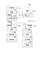
- FIG. 1 is a configuration diagram of an automatic driving vehicle development system including a vehicle control system using a vehicle control device according to a first embodiment.
- 1 is a configuration diagram of a vehicle control system according to a first embodiment.
- FIG. 3 is a functional configuration diagram of a first control unit 120, a second control unit 160, and a third control unit 170 according to the first embodiment. It is a flowchart which shows an example of the flow of a series of processes at the time of transmission of collection data.
- FIG. 5 is a diagram for explaining collected data to be transmitted and collected data not to be transmitted;
- FIG. 2 is a configuration diagram of a server device according to the first embodiment. It is a figure showing an example of a screen displayed on a terminal device of a developer.
- FIG. 1 is a configuration diagram of an automatic driving vehicle development system 1 including a vehicle control system 10 using a vehicle control device according to the first embodiment.
- the automatic driving vehicle development system 1 includes, for example, vehicle control systems 10-1 to 10-n mounted on each vehicle m, and a server device 300. These devices communicate via the radio base station BS and the network NW.
- wireless communication using a mobile phone network or the like is performed between each of the vehicle control systems 10-1 to 10-n and the wireless base station BS, and between the wireless base station BS and the server device 300.
- Wired communication using a network NW such as a WAN (Wide Area Network) is performed.
- Communication between each of the vehicle control systems 10-1 to 10-n and the server device 300 may be performed using a wireless communication device or the like installed at the roadside.
- the vehicle control systems 10-1 to 10-n are not particularly distinguished, they will be simply described as the vehicle control system 10.
- the vehicle control system 10 automatically controls the steering and speed of the vehicle m to automatically drive the vehicle m or collect various data when the occupant of the vehicle m is manually driving.
- the vehicle m on which the vehicle control system 10-1 is mounted may be a non-commercial vehicle such as a public vehicle, or a commercial vehicle such as a taxi, bus, or truck. It may be. Further, the vehicle m on which the vehicle control system 10-1 is mounted may be a vehicle that performs test traveling for the purpose of developing a vehicle (a so-called test vehicle or probe vehicle).
- the server device 300 receives the data collected by the vehicle control system 10 and provides the received data to a terminal device that can be used by a developer of the vehicle control system 10 or the like.
- the server device 300 is an example of an “external device”.
- FIG. 2 is a configuration diagram of the vehicle control system 10 according to the first embodiment.
- the vehicle on which the vehicle control system 10 is mounted (hereinafter, referred to as the host vehicle M) is, for example, a two-wheel, three-wheel, four-wheel, or other vehicle, and its driving source is an internal combustion engine such as a diesel engine or a gasoline engine, or an electric motor. Or a combination thereof.
- the electric motor operates using electric power generated by a generator connected to the internal combustion engine or electric power discharged from a secondary battery or a fuel cell.
- the vehicle control system 10 includes, for example, a camera 12, a radar device 14, a finder 16, an object recognition device 18, a communication device 20, an HMI (Human Machine Interface) 30, a vehicle sensor 40, and a navigation device 50. , MPU (Map @ Positioning @ Unit) 60, a driving operator 80, an automatic driving control device 100, a traveling driving force output device 200, a brake device 210, and a steering device 220. These devices and devices are connected to each other by a multiplex communication line such as a CAN (Controller Area Network) communication line, a serial communication line, a wireless communication network, or the like.
- CAN Controller Area Network
- serial communication line a wireless communication network
- the camera 12 is a digital camera using a solid-state imaging device such as a CCD (Charge Coupled Device) or a CMOS (Complementary Metal Oxide Semiconductor).
- the camera 12 is attached to an arbitrary position of the host vehicle M.
- the camera 12 is attached to the upper part of the front windshield, the rear surface of the rearview mirror, or the like.
- the camera 12 periodically and repeatedly takes images of the vicinity of the host vehicle M, for example.
- Camera 12 may be a stereo camera.
- the radar device 14 radiates radio waves such as millimeter waves around the own vehicle M and detects radio waves (reflected waves) reflected by the object to detect at least the position (distance and direction) of the object.
- the radar device 14 is attached to an arbitrary position of the host vehicle M.
- the radar device 14 may detect the position and the velocity of the object by an FM-CW (Frequency Modulated Continuous Wave) method.
- FM-CW Frequency Modulated Continuous Wave
- the finder 16 is a LIDAR (Light Detection and Ranging).
- the finder 16 irradiates light around the vehicle M and measures scattered light.
- the finder 16 detects the distance to the target based on the time from light emission to light reception.
- the light to be irradiated is, for example, a pulsed laser beam.
- the finder 16 is attached to an arbitrary position of the host vehicle M.
- the object recognition device 18 performs a sensor fusion process on the detection results of some or all of the camera 12, the radar device 14, and the finder 16 to recognize the position, type, speed, and the like of the object.
- the object recognition device 18 outputs a recognition result to the automatic driving control device 100.
- the object recognition device 18 may directly output the detection results of the camera 12, the radar device 14, and the finder 16 to the automatic driving control device 100.
- the object recognition device 18 may be omitted from the vehicle control system 10.
- the combination of the camera 12, the radar device 14, and the finder 16 described above is an example of a “second detection unit”, and the combination of the camera 12, the radar device 14, the finder 16, and the object recognition device 18 is referred to as a “second detection unit”. Section "is another example.
- the communication device 20 communicates with other vehicles existing around the host vehicle M using wireless communication such as a cellular network, a Wi-Fi network, Bluetooth (registered trademark), and DSRC (Dedicated Short Range Communication). Or communicates with the server device 300 via a wireless base station.
- the communication device 20 is an example of an “output unit”.
- the communication device 20 is an example of a “first communication unit”.
- the HMI 30 presents various information to the occupant of the host vehicle M and receives an input operation by the occupant.
- the HMI 30 includes various display devices, speakers, buzzers, touch panels, switches, keys, and the like.
- the vehicle sensor 40 includes a vehicle speed sensor that detects the speed of the own vehicle M, an acceleration sensor that detects acceleration, a yaw rate sensor that detects an angular velocity around a vertical axis, an azimuth sensor that detects the direction of the own vehicle M, and the like. Vehicle sensor 40 outputs a detection result to automatic driving control device 100.
- vehicle state information the detection result by the vehicle sensor 40 will be described as “vehicle state information”.
- the navigation device 50 includes, for example, a Global Navigation Satellite System (GNSS) receiver 51, a navigation HMI 52, and a route determination unit 53.
- GNSS Global Navigation Satellite System
- the navigation device 50 holds the first map information 54 in a storage device such as a hard disk drive (HDD) or a flash memory.
- HDD hard disk drive
- the GNSS receiver 51 specifies the position of the own vehicle M based on a signal received from a GNSS satellite.
- the position of the vehicle M may be specified or supplemented by an INS (Inertial Navigation System) using the output of the vehicle sensor 40.
- INS Inertial Navigation System
- the navigation HMI 52 includes a display device, a speaker, a touch panel, keys, and the like.
- the navigation HMI 52 may be partially or entirely shared with the above-described HMI 30.
- the route determining unit 53 may, for example, route from the position of the vehicle M specified by the GNSS receiver 51 (or an arbitrary position input) to a destination input by an occupant using the navigation HMI 52 (hereinafter, referred to as a route).
- the route on the map) is determined with reference to the first map information 54.
- the first map information 54 is, for example, information in which a road shape is represented by a link indicating a road and a node connected by the link.
- the first map information 54 may include curvature of a road, POI (Point of Interest) information, and the like.
- the route on the map is output to the MPU 60.
- the navigation device 50 may perform route guidance using the navigation HMI 52 based on the route on the map.
- the navigation device 50 may be realized by, for example, a function of a terminal device such as a smartphone or a tablet terminal owned by the occupant.
- the navigation device 50 may transmit the current position and the destination to the navigation server via the communication device 20, and acquire a route equivalent to the route on the map from the navigation server.
- the MPU 60 includes, for example, a recommended lane determining unit 61, and holds the second map information 62 in a storage device such as an HDD or a flash memory.
- the recommended lane determining unit 61 divides the route on the map provided from the navigation device 50 into a plurality of blocks (for example, divides every 100 [m] in the vehicle traveling direction), and refers to the second map information 62. Determine the recommended lane for each block.
- the recommended lane determining unit 61 determines which lane to travel from the left. When there is a branch point on the map route, the recommended lane determining unit 61 determines a recommended lane so that the vehicle M can travel on a reasonable route for traveling to the branch destination.
- the second map information 62 is more accurate map information than the first map information 54.
- the second map information 62 includes, for example, information on the center of the lane, information on the boundary of the lane, information on the type of the lane, and the like. Also, the second map information 62 may include road information, traffic regulation information, address information (address / postal code), facility information, telephone number information, and the like.
- the second map information 62 may be updated at any time by the communication device 20 communicating with another device.
- the driving operator 80 includes, for example, an accelerator pedal, a brake pedal, a shift lever, a steering wheel, a deformed steer, a joystick, and other operators.
- Each operation element included in the driving operation element 80 is provided with an operation detection sensor 80a.
- the operation detection sensor 80a detects an operation amount indicating how much the operator has been operated, or detects the presence or absence of an operation on the operator.
- the operation detection sensor 80a outputs the detected operation amount or information indicating the presence or absence of the detected operation (hereinafter, referred to as user operation information) to the automatic driving control device 100.
- the operation detection sensor 80a may output the user operation information to the traveling driving force output device 200, the brake device 210, and the steering device 220.
- the operation detection sensor 80a is an example of a “first detection unit”.
- the automatic driving control device 100 includes, for example, a first control unit 120, a second control unit 160, a third control unit 170, and a storage unit 180.
- the first control unit 120, the second control unit 160, and the third control unit 170 are realized by a processor such as a CPU (Central Processing Unit) or a GPU (Graphics Processing Unit) executing a program (software).
- a processor such as a CPU (Central Processing Unit) or a GPU (Graphics Processing Unit) executing a program (software).
- a part or all of the first control unit 120, the second control unit 160, and the third control unit 170 may be an LSI (Large Scale Integration), an ASIC (Application Specific Integrated Circuit), or an FPGA (Field-Programmable Gate Array). May be realized by hardware (including a circuit unit; circuitry), or may be realized by cooperation of software and hardware.
- the program referred to by the processor may be stored in the storage unit 180 of the automatic operation control device 100 in advance, or may be stored in a removable storage medium such as a DVD or a CD-ROM. It may be installed in the storage unit 180 by being attached to the drive device of the operation control device 100.
- the storage unit 180 is realized by, for example, an HDD, a flash memory, an electrically erasable programmable read only memory (EEPROM), a read only memory (ROM), or a random access memory (RAM).
- the storage unit 180 stores, for example, a control logic LG in addition to a program read and executed by the processor.
- the control logic LG is a program or a data structure representing a learning model such as a neural network.
- the control logic LG includes dictionary data, a first logic, and a second logic.
- Dictionary data is used when recognizing objects. For example, a template image to be compared at the time of pattern matching is registered in the dictionary data.
- the first logic outputs, for example, information indicating an event described later when a result of the sensor fusion processing by the object recognition device 18 or a detection result of each of the camera 12, the radar device 14, and the finder 16 is input.
- This is a model that has been learned in advance.
- the result of the sensor fusion processing by the object recognition device 18 and the detection results of the camera 12, the radar device 14, and the finder 16 will be described as "outside world information”.
- the second logic is a model that has been learned in advance so that, for example, when information output by the first logic is input, the state of the own vehicle M in the future is output.
- the state of the host vehicle M in the future includes, for example, position, speed, acceleration, jerk, steering angle, and the like.
- the state of the host vehicle M in the future may include the operation timing and operation time of devices such as a blinker, a display, and a speaker.
- control logic LG when the control logic LG receives external world information instead of the first logic and the second logic without outputting information indicating an event that is an intermediate operation result, the control logic LG eventually obtains the future information desired to be obtained.
- a logic learned in advance to output the state of the host vehicle M may be included.
- the control logic LG is a neural network
- the information representing the event may be treated as a feature quantity representing a calculation result of an intermediate layer of the neural network.
- FIG. 3 is a functional configuration diagram of the first control unit 120, the second control unit 160, and the third control unit 170 in the first embodiment.
- the first control unit 120 includes, for example, a recognition unit 130 and an action plan generation unit 140.
- the action plan generation unit 140 is an example of a “derivation unit”.
- the recognizing unit 130 and the action plan generating unit 140 refer to the control logic LG stored in the storage unit 180 to perform a function based on AI (Artificial Intelligence) and a function based on a given model in advance. Realize in parallel.
- AI Artificial Intelligence
- the "recognize intersection” function is based on intersection recognition using a machine learning method (deep learning) using a deep neural network and based on predetermined conditions (such as a signal capable of pattern matching and road marking). Recognition may be performed in parallel, and it may be realized by scoring and comprehensively evaluating both. Thereby, the reliability of the automatic driving is ensured.
- a machine learning method deep learning
- predetermined conditions such as a signal capable of pattern matching and road marking
- the recognition unit 130 recognizes the position of an object in the vicinity of the own vehicle M and the state such as the speed and the acceleration based on the external world information.
- the position of the object is recognized, for example, as a position on an absolute coordinate with the representative point (the center of gravity, the center of the drive shaft, etc.) of the vehicle M as the origin, and is used for control.
- the position of the object may be represented by a representative point such as the center of gravity or a corner of the object, or may be represented by a two-dimensional or more area.
- the “state” of the object may include acceleration or jerk of the object, or “action state” (for example, whether or not the vehicle is changing lanes or trying to change lanes).
- the recognition unit 130 recognizes, for example, a lane in which the host vehicle M is traveling (hereinafter, referred to as a host lane), an adjacent lane adjacent to the host lane, and the like with reference to dictionary data of the control logic LG. .
- a host lane a lane in which the host vehicle M is traveling
- an adjacent lane adjacent to the host lane and the like with reference to dictionary data of the control logic LG.
- the recognition unit 130 captures an image of the road division line pattern of the template image and an image captured by the camera 12.
- the own lane and the adjacent lane are recognized by performing pattern matching with the pattern of the road lane marking in the image.
- the recognition unit 130 refers to the dictionary data of the control logic LG to recognize objects representing road boundaries (road boundaries) such as road lane markings, road shoulders, curbs, median strips, and guardrails.
- road boundaries road boundaries
- the own lane or the adjacent lane may be recognized based on the relative positional relationship with the position of the object representing the boundary.
- the position of the host vehicle M acquired from the navigation device 50 and the processing result by the INS may be added.
- the recognizing unit 130 may recognize a pause line, an obstacle, a red light, a tollgate, and other objects by referring to the dictionary data of the control logic LG.
- the recognition unit 130 recognizes the relative position and posture of the own vehicle M with respect to the own lane.
- the recognizing unit 130 determines, for example, the deviation of the reference point of the vehicle M from the center of the lane, and the angle formed with respect to a line connecting the center of the lane in the traveling direction of the vehicle M, relative position of the vehicle M with respect to the vehicle lane. And posture. Instead, the recognizing unit 130 recognizes the position of the reference point of the own vehicle M with respect to any one of the side ends (the road division line or the road boundary) of the own lane as the relative position of the own vehicle M with respect to the own lane. May be.
- the action plan generation unit 140 adjusts the state of the host vehicle M, such as the future position and speed, in accordance with the change in the surrounding situation when the host vehicle M is running and the state of the host vehicle M. Is generated.
- the action plan generation unit 140 may include at least one of a detection result of a sensor such as the camera 12, the radar device 14, and the finder 16 or a recognition result of the recognition unit 130, and vehicle state information that is a detection result of the vehicle sensor 40 Is input to the first logic of the control logic LG by inputting the detection result of the control logic LG or the recognition result of the recognition unit 130 (preferably both the detection result of the sensor or the recognition result of the recognition unit 130 and the vehicle state information). Determines the event of the automatic driving on the determined route.
- the event is information that defines the traveling mode of the vehicle M.
- the event includes, for example, a constant speed traveling event in which the own vehicle M travels in the same lane at a constant speed, an event existing within a predetermined distance (for example, within 100 [m]) ahead of the own vehicle M, and A follow-up running event that causes the own vehicle M to follow a nearby other vehicle (hereinafter, referred to as a preceding vehicle), a lane change event that causes the own vehicle M to change lanes from the own lane to an adjacent lane, A branch event for branching to the destination lane, a merge event for joining the vehicle M to the main line at a junction, a takeover event for ending automatic driving and switching to manual driving, and the like are included.
- a constant speed traveling event in which the own vehicle M travels in the same lane at a constant speed
- an event existing within a predetermined distance for example, within 100 [m]
- a follow-up running event that causes the own vehicle M to follow a nearby other vehicle
- a lane change event that causes the own vehicle M to change la
- the “follow-up” may be, for example, a traveling mode in which the relative distance (inter-vehicle distance) between the own vehicle M and the preceding vehicle is maintained constant, or the relative distance between the own vehicle M and the preceding vehicle is constant.
- the driving mode may be such that the own vehicle M runs at the center of the own lane.
- the event includes, for example, an overtaking event in which the vehicle M is temporarily changed to an adjacent lane, the preceding vehicle is overtaken in the adjacent lane, and then the lane is changed back to the original lane.
- An avoidance event that causes the host vehicle M to perform at least one of braking and steering in order to avoid an obstacle may be included.
- the action plan generation unit 140 When determining the event indicating the traveling mode of the vehicle M based on the first logic, the action plan generation unit 140 inputs information indicating the event to the second logic of the control logic LG, thereby defining the event.
- a future target trajectory of the host vehicle M for automatically driving the host vehicle M in the driving mode (independent of the driver's operation) is generated.
- the target trajectory includes, for example, an element representing a state such as a future position or speed of the vehicle M.
- the action plan generation unit 140 generates a target trajectory in which a plurality of points (track points) to which the host vehicle M should sequentially reach are used as future position elements of the host vehicle M.
- the track point is a point that the vehicle M should reach every predetermined traveling distance (for example, about several [m]).
- the predetermined traveling distance may be calculated, for example, based on a road distance when traveling along the route.
- the action plan generation unit 140 generates a target trajectory using the target speed and the target acceleration for each predetermined sampling time (for example, about 0 commas [sec]) as future speed elements of the vehicle M.
- the track point may be a position to be reached by the vehicle M at the sampling time for each predetermined sampling time.
- the target speed and the target acceleration are determined by the sampling time and the interval between the orbit points.
- the action plan generation unit 140 outputs information indicating the generated target trajectory (hereinafter, referred to as target trajectory information) to the third control unit 170.
- the action plan generation unit 140 outputs the target trajectory information to the second control unit 160 in addition to or instead of the third control unit 170. I do.
- the second control unit 160 sets the target trajectory generated by the action plan generation unit 140 at the scheduled time.
- the traveling driving force output device 200, the brake device 210, and the steering device 220 are controlled so that the vehicle M passes through the vehicle.
- the second control unit 160 includes, for example, an acquisition unit 162, a speed control unit 164, and a steering control unit 166.
- the combination of the action plan generation unit 140 and the second control unit 160 is an example of an “operation control unit”.
- the acquisition unit 162 acquires information on the target trajectory (trajectory point) generated by the action plan generation unit 140 and stores the information in the memory of the storage unit 180.
- the speed control unit 164 controls one or both of the driving force output device 200 and the brake device 210 based on speed elements (for example, a target speed and a target acceleration) included in the target trajectory stored in the memory.
- speed elements for example, a target speed and a target acceleration
- the steering control unit 166 controls the steering device 220 according to a position element (for example, a curvature indicating the degree of curvature of the target trajectory) included in the target trajectory stored in the memory.
- a position element for example, a curvature indicating the degree of curvature of the target trajectory
- the processing of the speed control unit 164 and the steering control unit 166 is realized by, for example, a combination of feedforward control and feedback control.
- the steering control unit 166 executes a combination of the feedforward control according to the curvature of the road ahead of the host vehicle M and the feedback control based on the deviation from the target trajectory.
- the driving power output device 200 outputs driving power (torque) for driving the vehicle to driving wheels.
- the traveling driving force output device 200 includes, for example, a combination of an internal combustion engine, an electric motor, a transmission, and the like, and a power ECU (Electronic Control Unit) for controlling these.
- the power ECU controls the above configuration according to information input from the second control unit 160 or information input from the driving operator 80.
- the brake device 210 includes, for example, a brake caliper, a cylinder that transmits hydraulic pressure to the brake caliper, an electric motor that generates hydraulic pressure to the cylinder, and a brake ECU.
- the brake ECU controls the electric motor in accordance with the information input from the second control unit 160 or the information input from the driving operator 80 so that the braking torque corresponding to the braking operation is output to each wheel.
- the brake device 210 may include, as a backup, a mechanism that transmits a hydraulic pressure generated by operating a brake pedal included in the driving operator 80 to the cylinder via a master cylinder.
- the brake device 210 is not limited to the above-described configuration, and is an electronically controlled hydraulic brake device that controls the actuator according to information input from the second control unit 160 and transmits the hydraulic pressure of the master cylinder to the cylinder. Is also good.
- the steering device 220 includes, for example, a steering ECU and an electric motor.
- the electric motor changes the direction of the steered wheels by applying a force to a rack and pinion mechanism, for example.
- the steering ECU drives the electric motor according to the information input from the second control unit 160 or the information input from the driving operator 80 to change the direction of the steered wheels.
- the third control unit 170 includes, for example, a data collection unit 172, a determination unit 174, an output control unit 176, and an activation control unit 178.
- the data collection unit 172 collects (acquires) external world information from the object recognition device 18, the camera 12, the radar device 14, and the finder 16 and collects (acquires) vehicle state information from the vehicle sensor 40 at a predetermined cycle. And collecting (acquiring) user operation information from each operation detection sensor 80a of the driving operator 80 is repeated.
- the collected information will be collectively referred to as “collected data”.
- the data collection unit 172 causes the storage unit 180 to store the collected data. Further, the data collection unit 172 may acquire the target trajectory information from the action plan generation unit 140.
- the vehicle state information output by the vehicle sensor 40 under manual driving, the external information output by the object recognition device 18 or the camera 12, the radar device 14, and the finder 16, the user operation information, and the target trajectory information Collected data including a part or all of them is an example of “output information”.
- the determination unit 174 compares the user operation information collected by the data collection unit 172 with the target trajectory information output by the action plan generation unit 140, and compares the control logic LG stored in the storage unit 180 of the vehicle M. Is determined to be operating correctly.
- the determination unit 174 determines the behavior of the vehicle M indicated by the user operation information, that is, the behavior of the own vehicle M when the occupant manually drives (an example of the “first behavior”), and the behavior of the own vehicle M indicated by the target trajectory information. It is determined whether or not the behavior, that is, the behavior of the own vehicle M when assuming automatic driving (an example of the “second behavior”) is determined. It is determined that the control logic LG stored in the storage unit 180 is operating correctly, and when the behaviors of the control logic LG do not match, the control logic LG stored in the storage unit 180 of the host vehicle M is operating correctly. It is determined that there is not.
- the “case where automatic driving is assumed” is a case where the control logic LG is not activated, the target trajectory is simply generated, and the target trajectory information is not output to the second control unit 160. .
- the determination unit 174 determines the operation amount for each operation element included in the user operation information and the operation amount for each operation element that is derived when each element (speed, position, etc.) included in the target trajectory is set as a control amount. Are compared, and if the difference in the operation amount for each operation element is within a predetermined error range (for example, within a range of about several [%]), it is determined that the behaviors match, otherwise, the behaviors match. It is determined not to be performed. At this time, the error range may be different for each operator.
- a predetermined error range for example, within a range of about several [%]
- the predetermined error range for the difference in the operation amount of the accelerator pedal (such as the accelerator pedal opening) is 0 to 5%
- the predetermined error range for the difference in the operation amount of the brake pedal (such as the opening of the brake pedal) is
- the predetermined error range with respect to the difference in the steering wheel operation amount (such as steering torque and steering angle) may be 0 to 10%. This numerical range is merely an example, and may be arbitrarily changed.
- the determining unit 174 determines that the behaviors match when the traveling direction of the own vehicle M when the occupant performs the manual driving and the traveling direction of the own vehicle M when the automatic driving is assumed to match. However, when the traveling direction of the own vehicle M when the occupant performs the manual driving and the traveling direction of the own vehicle M assuming the automatic driving do not match each other, it may be determined that the respective behaviors do not match. . For example, when the difference in the operation amount of the steering wheel is within a predetermined error range, that is, when the difference in the steering angle is within the predetermined error range, It may be determined that the traveling direction and the traveling direction of the own vehicle M assuming automatic driving match each other, and otherwise, it may be determined that the traveling directions do not match each other.
- the determination unit 174 determines the behavior of the own vehicle M under the manual operation and the behavior of the own vehicle M under the virtual automatic operation until the own vehicle M travels a predetermined distance or the predetermined time elapses. And the number of times they do not match (hereinafter referred to as the first number of non-matches) are counted, and the first number of matches is counted as the total number of times (the first number of matches).
- a predetermined ratio for example, about 95 [%]
- the first number of matches is an example of a “first number”
- the first non-match number is an example of a “second number”.
- the output control unit 176 controls the communication device 20 to make the server device 300 Send collected data.
- the activation control unit 178 receives, from the server device 300 via the communication device 20, activation enable / disable information indicating permission or prohibition of activation of the control logic LG, and based on the received activation enable / disable information. Activate the control logic LG.
- the activation control unit 178 when the activation control unit 178 receives the activation permission / inhibition information indicating permission of activation, the activation control unit 178 enables some or all of the dictionary data of the control logic LG, the first logic, and the second logic. By doing so, the control logic LG may be activated. Accordingly, the second control unit 160 can control the steering and the speed of the own vehicle M based on the target trajectory, and the automatic driving of the own vehicle M is performed.
- the activation control unit 178 when the activation control unit 178 receives the activation permission / prohibition information indicating the prohibition of activation, the activation control unit 178 invalidates all the functions of the dictionary data, the first logic, and the second logic of the control logic LG, thereby controlling the control logic LG.
- the LG may be deactivated.
- the target trajectory information is not output from the action plan generation unit 140 to the second control unit 160, the steering and speed of the own vehicle M are not controlled (the automatic driving is not performed), and the driving operator under the manual driving is not operated. Only the comparison between the operation amount of the driving operator 80 and the operation amount of the driving operator 80 under the virtual automatic driving is performed.
- the activation control unit 178 may activate or deactivate the control logic LG according to the determination result of the determination unit 174 without depending on the activation availability information. For example, the activation control unit 178 activates the control logic LG when the determination unit 174 determines that the control logic LG stored in the storage unit 180 of the own vehicle M is operating correctly. , The control logic LG may be deactivated.
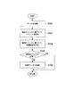
- FIG. 4 is a flowchart illustrating an example of a flow of a series of processes when transmitting collected data.
- the processing of this flowchart may be repeatedly performed at a predetermined cycle, for example.
- the data collection unit 172 collects external world information, vehicle state information, and user operation information as collection data (step S100).
- the action plan generation unit 140 outputs the external information, which is the detection result of the object recognition device 18 or the camera 12, the radar device 14, and the finder 16, and the detection result of the vehicle sensor 40. From the vehicle state information, an event of automatic driving is determined on the route on which the recommended lane has been determined (step S102).
- the action plan generation unit 140 generates a future target trajectory of the vehicle M from events in each section of the route based on the control logic LG (step S104).
- the determination unit 174 determines the behavior of the own vehicle M under manual driving indicated by the user operation information collected by the data collection unit 172 and the virtual automatic driving indicated by the target trajectory information output by the action plan generation unit 140. Then, it is determined whether or not the control logic LG stored in the storage unit 180 of the host vehicle M is operating correctly by comparing the behavior of the host vehicle M at (Step S106).
- the output control unit 176 controls the communication device 20 to transmit the collected data to the server device 300 (step S108). At this time, the output control unit 176 may transmit target trajectory information as collected data in addition to the external world information, the vehicle state information, and the user operation information.
- the output control unit 176 omits the process of S108 and does not transmit the collected data to the server device 300.
- the processing of this flowchart ends.
- the output control unit 176 controls the communication device 20 when the determination unit 174 determines that the control logic LG is not operating correctly, and sends the collected data to the server device 300. Is described, but the present invention is not limited to this.
- the output control unit 176 outputs the collected data to a non-temporary storage medium such as an HDD included in the storage unit 180.
- the collected data may be stored in the non-temporary storage medium.
- the car dealer copies the collected data from the storage medium in which the collected data is stored to another storage medium, and uploads the collected data to the server device 300 from the storage medium.
- a communication interface (not shown) connected to a non-transitory storage medium such as an HDD included in the storage unit 180 is another example of the “output unit”.
- the communication interface connected to the non-transitory storage medium may include, for example, Direct Memory Access Controller.
- FIG. 5 is a diagram for explaining collected data to be transmitted and collected data not to be transmitted.
- the horizontal axis represents time
- the vertical axis represents the operation amount.
- a solid line L1 represents a change in the operation amount of the driving operator 80 under the manual operation
- a broken line L2 represents a change in the operation amount of the driving operator 80 under the virtual automatic operation.
- the output control unit 176 does not transmit the collected data collected during the period from time t0 to t1, the period from time t2 to t3, and the period after time t4 to the server device 300.
- the determination unit 174 determines the behavior of the own vehicle M under manual driving and the virtual automatic driving. It is determined that the behavior of the own vehicle M below does not match each other. Therefore, the output control unit 176 transmits the collected data collected in the period from the time t1 to the time t2 and in the period from the time t3 to the time t4 to the server device 300.
- the output control unit 176 transmits the collected data collected during the period from time t1 to t2 to the server device 300 at any timing (time) after time t2, and collects the collected data during the period from time t3 to t4.
- the collected data may be transmitted to the server device 300 at any timing (time) after the time t4. More specifically, the output control unit 176 may transmit the collected data at a timing when the determination result that the behaviors do not match each other changes to a determination result that the behaviors match each other. Alternatively, the collected data may be transmitted at a timing when the vehicle is parked in a parking lot. In addition, the output control unit 176 may transmit the collected data when the vehicle M is traveling in a section where a constant-speed traveling event can be planned, such as a highway.
- FIG. 6 is a configuration diagram of the server device 300 according to the first embodiment.
- the server device 300 includes, for example, a server-side communication unit 302, a server-side control unit 310, and a server-side storage unit 330.
- the server-side communication unit 302 includes, for example, a communication interface such as an NIC (Network Interface Card).
- the server side communication unit 302 communicates with each of the vehicle control systems 10 of each vehicle via the network NW, and receives collected data from the vehicle control system 10 of each vehicle.
- the server-side communication unit 302 is an example of a “second communication unit”.
- the server-side control unit 310 includes, for example, an information providing unit 312 and a logic updating unit 314. These components are realized by a hardware processor (or a processor circuit) such as a CPU or a GPU executing a program (software) stored in the server-side storage unit 330. Some or all of these components may be realized by hardware (circuitry) such as an LSI, an ASIC, or an FPGA, or may be realized by cooperation of software and hardware. Is also good. Further, the above-described program may be stored in the server-side storage unit 330 in advance, or may be stored in a removable storage medium such as a DVD or a CD-ROM. It may be installed in the server-side storage unit 330 from a storage medium by being attached.
- the server-side storage unit 330 is realized by a storage device such as an HDD, a flash memory, an EEPROM, a ROM, and a RAM.
- the server-side storage unit 330 stores control logic LG and the like in addition to various programs such as firmware and application programs.
- the information providing unit 312 displays a screen for inquiring whether to use the collected data as the teacher data of the control logic LG on a website or the like.
- the teacher data is data in which data given as an example is previously associated with data that is a correct answer to the example.
- the terminal device of the developer may be, for example, a mobile phone such as a smartphone, a tablet terminal, various personal computers, or the like.
- the logic update unit 314 learns and updates the control logic LG by supervised learning based on, for example, the collected data received by the server-side communication unit 302.
- the logic update unit 314 is an example of a “determination unit”.
- FIG. 7 is a diagram showing an example of a screen displayed on the terminal device of the developer.
- the information providing unit 312 displays, on the screen of the terminal device of the developer, the operation amount of the driving operator 80 under the manual driving, which is the reason why the collected data is transmitted by the vehicle control system 10, and the virtual automatic driving It may be displayed as a character or an image that the amount of operation for each of the operators is assumed to be different.
- switches SW1 and SW2 in the figure
- a switch SW3 for allowing the developer to check the collected data before determining whether the operation amount of the driving operator 80 under the manual driving is used as the teacher data is displayed. It may be displayed.
- the logic update unit 314 uses the vehicle state information and the external world information included in the collected data to identify the identification information indicating the behavior of the vehicle to be output.
- the teacher label may be, for example, a control amount derived based on the operation amount of the driving operator 80 under the manual operation, which is different from the operation amount of each operator assumed under the virtual automatic driving.
- the logic updating unit 314 updates the new control logic LG by learning the current control logic LG based on the teacher data.
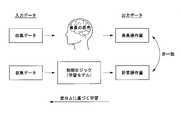
- FIG. 8 is a diagram schematically showing how the control logic LG is updated.
- the control logic LG For example, under manual driving, the amount of operation on the driving operator 80 is sensibly (unconsciously) determined by the occupant.
- the operation amount for the driving operator 80 is determined by the control logic LG.
- the logic update unit 314 uses the operation amount (the occupant operation amount in the figure) of the driving operator 80 under the manual driving as the teacher data, and uses the operation amount (the operation figure) of the driving operator 80 calculated by the control logic LG.
- the control logic LG is learned using a gradient method such as a probability theory or an error back propagation method so that the difference ⁇ between the calculation operation amount) and the occupant operation amount as the teacher data is reduced. Thereby, it is possible to update the control logic LG closer to the occupant's thinking.
- the logic update unit 314 excludes the vehicle state information and the outside world information included in the collected data from the teacher data.
- the information providing unit 312 causes the vehicle state information and the external world information included in the collected data to be displayed on the screen of the terminal device as images, graphs, and numerical values. Accordingly, the developer can visually confirm the image of the camera 12 and the like while operating the driving operator 80 (manual operation amount) under the manual driving and operating the respective operators expected under the virtual automatic driving. When the amount (calculated operation amount) deviates, it is possible to confirm which of the manual operation and the automatic operation is the more correct operation.
- the lane is not recognized by the recognition unit 130. It can be determined that there is a high probability that an object or an event to be avoided exists in front of the vehicle M. In such a case, if the developer visually confirms an image or the like of the camera 12 and finds that an object or an event to be avoided exists in front of the own vehicle M, the developer is required to manually drive the vehicle. Can be concluded to be correct. In this case, in order to update the control logic LG, the developer operates the switch SW1 on the screen of the terminal device to use the vehicle state information and the outside world information included in the collected data as teacher data.
- the developer operates the switch SW2 on the screen of the terminal device to prevent the control logic LG from learning using the collected data for which the situation determination is ambiguous, and obtains the vehicle state information included in the collected data.
- the outside world information is excluded from the teacher data.
- the developer can select the collected data to be used as the teacher data of the control logic LG, and thereby generate the control logic LG with higher accuracy (closer to the occupant's thinking).
- teacher data of the control logic LG can be obtained. May be generated.
- the developer may upload the generated teacher data to the server device 300 using the terminal device.
- the logic updating unit 314 updates the new control logic LG by learning the current control logic LG based on the teacher data.
- the logic update unit 314 controls the server-side communication unit 302 to notify the vehicle control system 10 of each vehicle with the updated control logic LG and the activation permission / inhibition indicating permission of activation. Information and may be sent. Thereby, the vehicle control system 10 of each vehicle can activate the updated control logic LG and perform automatic driving.
- the vehicle control system 10 when the vehicle control system 10 receives the updated control logic LG and the activation permission / inhibition information indicating the permission of activation, the vehicle control system 10 further deactivates the updated control logic LG and deactivates the control logic LG. Deriving the behavior of the own vehicle M assumed under virtual automatic driving based on the control logic LG, and determining whether the derived behavior matches the behavior of the own vehicle M under the current manual driving. Is determined, and when it is determined that the behaviors match each other, the deactivated control logic LG may be activated. As described above, the control logic LG updated by the server device 300 may not be immediately activated, but may be activated once after being verified on the vehicle side.
- the logic update unit 314 compares the collected data to update the updated control logic LG. Instead of updating (the control logic LG stored in the storage unit 180 of each vehicle), it may be determined whether or not to activate the updated control logic LG.
- the logic update unit 314 determines the behavior (manual operation) of each vehicle indicated by the user operation information.
- a first population which is a collection of behaviors of each vehicle under driving
- a second population which is a collection of behaviors of each vehicle (behavior of each vehicle under virtual automatic driving) indicated by the target trajectory information, are compared with each other. Then, it may be determined whether or not to activate the updated control logic LG.
- the logic update unit 314 determines the behaviors of the plurality of vehicles included in the first population under the manual operation (an example of the first behavior) and the plurality of vehicles included in the second population.
- the number of combinations in which the behavior under the virtual automatic driving (an example of the second behavior) matches each other is counted, and the number of the counted combinations is counted as the number of all combinations (the number of combinations in which each behavior matches and each behavior).
- a predetermined ratio for example, 95 [%]
- activation permission / inhibition information indicating permission of activation may be transmitted to the vehicle control system 10 of each vehicle.
- the logic update unit 314 controls the server-side communication unit 302 to prohibit activation of the updated control logic LG. Then, activation availability information indicating prohibition of activation may be transmitted to the vehicle control system 10 of each vehicle.
- the server device 300 acquires collected data from each of the plurality of vehicles on which the vehicle control system 10 is mounted, and determines whether to activate the control logic LG. With the vehicle M only), it is possible to accumulate more and more collected data in the server device 300 faster than when collecting various types of information such as vehicle state information, external world information, user operation information, and target trajectory information.
- the control logic LG can be verified in a shorter time. Further, by verifying the control logic LG based on more collected data, it is possible to more accurately test (verify) the control logic LG.
- the logic update unit 314 counts the number of behavioral combinations in which the developer can conclude that the manual operation of the occupant is more correct when comparing the first population with the second population. If the ratio obtained by dividing the counted number by the number of all combinations is less than a predetermined ratio (for example, 5%), the server-side communication unit 302 allows the activation of the updated control logic LG. May be transmitted to the vehicle control system 10 of each vehicle.
- a predetermined ratio for example, 5%
- the communication device 20 that transmits information (an example of an output unit) and the operation detection sensor 80a that detects the operation amount of the driving operator 80 as the behavior of the vehicle (the first detection unit).
- a vehicle sensor 40 for detecting a state of the vehicle
- a camera 12 for detecting a state of the vehicle
- a radar device 14 for recognizing a situation around the vehicle
- a storage unit 180 for storing control logic LG.
- An action plan generation unit 140 (an example of a derivation unit) that generates a target trajectory is associated with each operation element detected by the operation detection sensor 80a under manual driving.
- the operation amount of the vehicle M under manual driving (by comparing the operation amount of the vehicle M under manual driving with the operation amount of each operation element that is derived when each element (speed, position, and the like) included in the target trajectory is set as the control amount is compared.
- the control logic LG accurately determines whether or not the behavior of the host vehicle M (an example of the second behavior) assumed under virtual automatic driving matches the example of the first behavior.
- the determination unit 174 that determines whether or not the vehicle is operating, and the control logic LG is not correctly operated by the determination unit 174 (for example, the behavior of the own vehicle M in the manual driving and the virtual automatic driving Is determined that the behavior of the own vehicle M does not coincide with each other), collected data (an example of output information) including at least vehicle state information and external world information is transmitted to the server device via the communication device 20.
- Output system to send to 300 And parts 176 by providing the developer is able to validate the control logic LG in detail.
- the server device 300 since the collected data is not transmitted to the user, the amount of communication data can be reduced.
- external information, vehicle state information, and user operation information are collected from the vehicle control system 10 mounted on a public vehicle or the like. Also, it is possible to shorten the time required for data collection and collect data comprehensively (widely) from the viewpoint of a plurality of traveling routes and a plurality of users.
- the vehicle control system 10 uses the user operation information indicating the user's operation amount for each operation element and each element (such as speed and position) included in the target trajectory as the control amount. Verifying the accuracy of the control logic LG using, among raw data including at least the external information, of the target trajectory information indicating the operation amount for each of the operators, which is derived when the operation is performed, and the external information. Can be.
- control logic since the control logic is deactivated, it is possible to collect the outside world information, the vehicle state information, and the user operation information without making the occupant particularly conscious under the manual driving.
- the collected data is transmitted to the server device 300, so that the driving operation of the occupant is correct.
- the operation amount of the driving operator 80 under manual driving is associated as a teacher label (correct data) with the vehicle state information and the external world information included in the collected data. The task of assigning a teacher label while sequentially checking collected data can be omitted.
- the activation control unit 178 determines, by the determination unit 174, that the behavior of the own vehicle M when the occupant performs the manual driving and the behavior of the own vehicle M when the occupant is assumed to perform the automatic driving are mutually different. It has been described that the control logic LG is activated when it is determined that the control logic LG is operating correctly, for example, due to a match. On the other hand, in the second embodiment, the activation control unit 178 activates the control logic LG even when the determination unit 174 determines that the control logic LG is not operating correctly. This is different from the first embodiment described above. Hereinafter, differences from the first embodiment will be mainly described, and descriptions of functions and the like common to the first embodiment will be omitted.
- the manual driving operation by the occupant is further performed based on the surrounding situation of the own vehicle M recognized by the recognition unit 130. It is determined whether the operation is a predetermined driving operation.
- the predetermined driving operation is, for example, a driving that neglects monitoring around the vehicle M, such as an inattentive driving or a dozing driving.
- the determination unit 174 determines that the manual driving operation by the occupant is the predetermined driving operation. The determination may be made, or when the vehicle M is separated from the center of the vehicle lane recognized by the recognition unit 130 by a predetermined distance or more, the manual driving operation by the occupant may be determined to be the predetermined driving operation.
- the activation control unit 178 in the second embodiment is a case where the determination unit 174 determines that the manual driving operation by the occupant is the predetermined driving operation, and determines that the control logic LG is not operating correctly. The control logic LG is also activated. As a result, the second control unit 160 automatically drives the own vehicle M in place of the occupant who is likely to perform inattentive driving or drowsy driving.
- the determination unit 174 in the second embodiment considers that there is a possibility that a predetermined driving operation may be performed by an occupant, and determines whether the vehicle M travels a predetermined distance or a predetermined time elapses. During the period, the number of times that the behavior of the own vehicle M when the occupant performs the predetermined driving operation (an example of the “third behavior”) does not match the behavior of the own vehicle M under virtual automatic driving (hereinafter, referred to as “the third behavior”).
- the third non-matching number is an example of a “third number”
- the third matching number is an example of a “fourth number”.
- the activation control unit 178 in the second embodiment activates the control logic LG in response to the determination unit 174 determining that the control logic LG is not operating correctly. Accordingly, the target trajectory information is output to the second control unit 160 by the action plan generation unit 140, so that the second control unit 160 controls the steering and speed of the vehicle M based on the target trajectory indicated by the target trajectory information. To perform automatic operation.
- the behavior of the own vehicle M when the occupant performs the manual driving and the behavior of the own vehicle M when the occupant is assumed to perform the automatic driving are determined to be different from each other.
- the own vehicle M is automatically driven, the safety of the occupant can be further improved.
- the storage unit 180 stores the control logic LG of the version with the new update date and time and the control logic LG of the version with the old update date and time, and stores the control logic LG of the old version.
- the behavior of the self-vehicle M under actual automatic driving based on the old version of the control logic LG and the virtual autonomous driving based on the new version of the control logic LG It differs from the above-described first and second embodiments in that the behavior of the host vehicle M below is compared with each other.
- a description will be given focusing on differences from the first embodiment and the second embodiment, and a description of functions and the like common to the first embodiment and the second embodiment will be omitted.
- FIG. 9 is a functional configuration diagram of the first control unit 120, the second control unit 160, and the third control unit 170 in the third embodiment.
- the storage unit 180 stores a first control logic LG1 and a second control logic LG2.
- the first control logic LG1 is an old version of the control logic LG whose update date and time is old, and may be, for example, a data structure or a program for executing ADAS (Advanced @ driver- @ assistance @ systems) for assisting the driver in driving.
- the second control logic LG2 is the latest version of the control logic LG with the latest update date and time, and may be, for example, a data structure or a program for performing automatic operation.
- Each of the first control logic LG1 and the second control logic LG2 may include dictionary data, a first logic, and a second logic. In the present embodiment, it is assumed that, of the first control logic LG1 and the second control logic LG2, the first control logic LG1 is activated and the second control logic LG2 is deactivated.
- the recognition unit 130 in the third embodiment includes, for example, a first recognition unit 130a and a second recognition unit 130b.
- the first recognizing unit 130a refers to the dictionary data of the first control logic LG1 stored in the storage unit 180, recognizes the own lane, the adjacent lane, the lane boundary, and the like, and based on the outside world information, the own vehicle M Recognize the state of an object around.
- the second recognizing unit 130b refers to the dictionary data of the second control logic LG2 stored in the storage unit 180 to recognize the own lane, the adjacent lane, the lane boundary, and the like, and based on the outside world information, the own vehicle M Recognize the state of an object around.
- the action plan generator 140 in the third embodiment includes, for example, a first generator 140a and a second generator 140b.
- the first generation unit 140a generates a target trajectory (hereinafter, referred to as a first target trajectory) based on the first control logic LG1 stored in the storage unit 180.
- the first generation unit 140a includes, in the first logic included in the first control logic LG1, a detection result of a sensor such as the camera 12, the radar device 14, and the finder 16 or a recognition result of the recognition unit 130, and a detection result of the vehicle sensor 40.
- the automatic driving event is determined by inputting the vehicle state information as the detection result, and the information indicating the determined event is input to the second logic included in the first control logic LG1, thereby obtaining the first target. Generate a trajectory.
- the first generation unit 140a transmits the target trajectory information indicating the first target trajectory generated based on the first control logic LG1 to the second control unit 160 and the third trajectory. Output to the control unit 170.
- the second generation unit 140b generates a target trajectory (hereinafter, referred to as a second target trajectory) based on the second control logic LG2 stored in the storage unit 180.
- the second generation unit 140b includes, in the first logic included in the second control logic LG2, a detection result of a sensor such as the camera 12, the radar device 14, the finder 16 or a recognition result of the recognition unit 130, and a recognition result of the vehicle sensor 40.
- the automatic driving event is determined by inputting the vehicle state information that is the detection result, and the information representing the determined event is input to the second logic included in the second control logic LG2, so that the second target is determined. Generate a trajectory.
- the second generation unit 140b outputs target trajectory information indicating the second target trajectory generated based on the second control logic LG2 to the third control unit 170. I do.
- the second control unit 160 is configured to output the traveling driving force output device 200, the brake device 210, and the vehicle so that the vehicle M passes the target track generated by the first generation unit 140a at a scheduled time. And the steering device 220.
- the data collection unit 172 in the third embodiment collects external information from the object recognition device 18, the camera 12, the radar device 14, and the finder 16 at a predetermined cycle, and collects vehicle state information from the vehicle sensor 40. The operation of collecting user operation information from each operation detection sensor 80a of the driving operator 80 is repeated. In addition, the data collection unit 172 acquires target trajectory information from each of the first generation unit 140a and the second generation unit 140b.
- the determination unit 174 in the third embodiment compares the target trajectory information collected by the data collection unit 172 from each of the first generation unit 140a and the second generation unit 140b with each other and stores the target trajectory information in the storage unit 180 of the vehicle M. It is determined whether or not the performed second control logic LG2 is operating correctly.
- the determination unit 174 determines that the behavior of the own vehicle M when following the first target trajectory matches the behavior of the own vehicle M when following the second target trajectory, that is, the first control logic LG1. If the behavior of the own vehicle M under automatic driving based on the above and the behavior of the own vehicle M under virtual automatic driving based on the second control logic LG2 match, the first control logic LG1 is assumed to be correct, 2 It is determined that the control logic LG2 is operating correctly.
- the determination unit 174 determines that the behavior of the own vehicle M when following the first target trajectory does not match the behavior of the own vehicle M when following the second target trajectory, that is, the first control logic LG1. If the behavior of the own vehicle M under automatic driving based on the above does not match the behavior of the own vehicle M under virtual automatic driving based on the second control logic LG2, the first control logic LG1 is assumed to be correct, 2 It is determined that the control logic LG2 is not operating correctly.
- the determination unit 174 follows the first target trajectory until the host vehicle M travels a predetermined distance or a predetermined time elapses, as in the first embodiment described above.
- the determination unit 174 determines that the second control logic LG2 is correct, instead of determining whether the second control logic LG2 is operating correctly, on the assumption that the first control logic LG1 is correct. Based on this assumption, it may be determined whether or not the first control logic LG1 is operating correctly.
- the output control unit 176 in the third embodiment communicates when the determination unit 174 determines that the second control logic LG2 is not operating correctly under the assumption that the first control logic LG1 is correct.
- the device 20 is controlled to transmit the collected data to the server device 300.
- the output control unit 176 controls the communication device 20 when the determination unit 174 determines that the first control logic LG1 is not operating correctly under the assumption that the second control logic LG2 is correct. Then, the collected data may be transmitted to the server device 300.
- At least the second control logic LG2 of the first control logic LG1 and the second control logic LG2 is stored in the server-side storage unit 330 of the server device 300 according to the third embodiment.
- the information providing unit 312 displays a screen for inquiring whether to use the collected data as teacher data for the control logic LG. To the terminal device of the developer via a website or the like.
- the developer checks the collected data provided to the terminal device and determines whether or not the second control logic LG2 has been correctly operated based on a situation around the vehicle at the time of data collection.
- the developer determines that the assumption that the first control logic LG1 is correct is incorrect, and uses the terminal device to execute the server device 300.
- the information indicating that the second control logic LG2 operates properly is transmitted.
- the developer uses the terminal device to notify the server device 300 of information indicating that the second control logic LG2 is not correctly operated.
- the logic update unit 314 in the third embodiment updates the server-side communication unit 302 when the server-side communication unit 302 receives information indicating that the second control logic LG2 operates correctly from the terminal device of the developer.
- the activation control unit 10 transmits activation enable / disable information indicating that activation of the second control logic LG2 is permitted and activation of the first control logic LG1 is prohibited to the vehicle control system 10 of each vehicle.
- the activated control logic LG is switched from the first control logic LG1 to a better version of the second control logic LG2 than the first control logic LG1.
- the logic update unit 314 based on the received collected data, The second control logic LG2 is learned and updated by supervised learning.
- the logic updating unit 314 generates teacher data based on the collected data collected when the second control logic LG2 is not operating correctly, and generates the teacher data.
- a new version of the control logic LG in which the second control logic LG2 is updated (hereinafter, referred to as a third control logic LG3) is generated.
- the logic update unit 314 controls the server-side communication unit 302 to cause the vehicle control system 10 of each vehicle to activate the third control logic LG3 and the activation of the third control logic LG3.
- the activation permission / inhibition information indicating prohibition is transmitted.
- the activation control unit 178 in the third embodiment allows the activation of the second control logic LG2 from the server 300 via the communication device 20 and prohibits the activation of the first control logic LG1.
- the second control logic LG2 stored in the storage unit 180 is activated, and the first control logic LG1 is deactivated.
- the second control unit 160 can control the steering and the speed of the own vehicle M based on the second target trajectory, and the automatic operation of the own vehicle M based on the second control logic LG2 is performed.
- the activation control unit 178 stores the third control logic LG3 and the activation permission / prohibition information indicating that activation of the third control logic LG3 is prohibited from the server device 300 via the communication device 20.
- the third control logic LG3 is written into the unit 180, and the third control logic LG3 is deactivated.
- the first recognition unit 130a and the first generation unit 140a perform the above-described processing based on the first control logic LG1
- the second recognition unit 130b and the second generation unit 140b perform the above-described processing based on the third control logic LG3.
- Performed processing As a result, under the assumption that the first control logic LG1 is correct, it is determined whether or not the third control logic LG3 is operating correctly, and it is determined that the third control logic LG3 is not operating correctly. In this case, the collected data is transmitted to the server device 300.
- the first control unit 120 may execute the second control logic LG2 according to the processing load when executing the first control logic LG1.
- the second recognizing unit 130b and the second generating unit 140b are provided by the processor realizing the first control unit 120 when the first control logic LG1 is being executed by the first recognizing unit 130a and the first generating unit 140a.
- the usage rate may be monitored, and if the usage rate of the processor is equal to or greater than the threshold, the second control logic LG2 may not be executed. If the usage rate of the processor is less than the threshold, the second control logic LG2 may be executed. As a result, it is possible to secure processing resources required for performing the automatic operation.
- the logic update unit 314 updates the teacher data. It has been described that the second control logic LG2 is learned based on this to generate a new version of the third control logic LG3 in which the second control logic LG2 is updated.
- the present invention is not limited to this.
- the logic update unit 314 performs a third control from the existing second control logic LG2. Instead of generating the logic LG3, the other control logic LG generated in parallel with the second control logic LG2 or the like is used as the third control logic LG3. May be replaced by the control logic LG.
- the second control The description has been made as to compare the behavior of the vehicle M (virtual behavior) when the own vehicle M is virtually automatically driven based on the target trajectory obtained by executing the logic LG2, but is not limited thereto.
- the virtual behavior of the vehicle M based on the first control logic LG1 and the virtual behavior of the vehicle M based on the second control logic LG2 are not generated by the first control logic LG1. You may compare.
- the control logic LG to be activated is updated from the first control logic LG1, which has already ensured a certain degree of reliability, with an update date and time.
- the second control logic LG2 can be verified without changing to the new second control logic LG2.
- the collected data is transmitted to the server device 300.
- the developer can check the collected data transmitted to the server device 300 to check whether the second control logic LG2 has been correctly operated. If the developer confirms that the second control logic LG2 has been operating correctly, the assumption that the first control logic LG1 is correct is incorrect and the second control logic LG1 has a lower value than the first control logic LG1. Since the logic LG2 can be regarded as having higher accuracy, the server device 300 causes each vehicle equipped with the vehicle control system 10 to deactivate the first control logic LG1 and activate the second control logic LG2. The activation information is transmitted. As a result, it is possible to perform automatic driving that can flexibly respond to the situation around the host vehicle M.
- FIG. 10 is a diagram illustrating an example of a hardware configuration of the automatic driving control device 100 and the server device 300 according to the embodiment.
- the automatic driving control apparatus 100 includes a communication controller 100-1, a CPU 100-2, a RAM 100-3 used as a working memory, a ROM 100-4 storing a boot program and the like, and a storage device such as a flash memory or an HDD.
- 100-5, a drive device 100-6, and the like are interconnected by an internal bus or a dedicated communication line.
- the communication controller 100-1 communicates with components other than the automatic operation control device 100.
- the storage device 100-5 stores a program 100-5a executed by the CPU 100-2 and a control logic LG.
- the program 100-5a is developed in the RAM 100-3 by a DMA (Direct Memory Access) controller (not shown) or the like, and is executed by the CPU 100-2.
- DMA Direct Memory Access
- the server device 300 includes a communication controller 300-1, a CPU 300-2, a RAM 300-3 used as a working memory, a ROM 300-4 storing a boot program and the like, a storage device 300-5 such as a flash memory or an HDD, and a drive.
- the apparatus 300-6 and the like are connected to each other by an internal bus or a dedicated communication line.
- the communication controller 300-1 communicates with the automatic driving control device 100 and the like.
- the storage device 300-5 stores a program 300-5a executed by the CPU 300-2.
- the program 300-5a is developed in the RAM 300-3 by a DMA controller (not shown) or the like and executed by the CPU 300-2. Thereby, the server-side control unit 310 is realized.
- a first detection unit that detects a behavior of the vehicle
- a second detection unit that detects a situation around the vehicle
- a storage for storing a first program learned to output information indicating the behavior of the vehicle when at least information indicating a situation surrounding the vehicle is input, and a certain second program
- the processor comprises: By executing the first program, the behavior of the vehicle is derived based on at least the surrounding situation of the vehicle detected by the second detection unit, By executing the second program, based on the first behavior of the vehicle detected by the first detection unit at a certain reference time and the surrounding situation detected by the second detection unit at the reference time Comparing the second behavior of the vehicle derived by executing the first program to determine whether or not the first program is operating correctly;
- the vehicle control device is configured as follows.
- SYMBOLS 1 Automatic driving vehicle development system, 10 ... Vehicle control system, 12 ... Camera, 14 ... Radar device, 16 ... Finder, 18 ... Object recognition device, 20 ... Communication device, 30 ... HMI, 40 ... Vehicle sensor, 50 ... Navigation Device, 60 MPU, 80 driving operator, 100 automatic driving control device, 120 first control unit, 130 recognition unit, 140 action plan generation unit, 160 second control unit, 162 acquisition unit, 164: speed control unit, 166: steering control unit, 170: third control unit, 172: data collection unit, 174: determination unit, 176: output control unit, 178: activate control unit, 180: storage unit, 200 ...
- Running driving force output device 210: brake device, 220: steering device, 300: server device, 302: server-side communication unit, 310: server-side control unit, 31 ... information providing unit, 314 ... logic updating unit, 330 ... server-side storage unit
Landscapes
- Engineering & Computer Science (AREA)
- Automation & Control Theory (AREA)
- Transportation (AREA)
- Mechanical Engineering (AREA)
- Human Computer Interaction (AREA)
- Combustion & Propulsion (AREA)
- Chemical & Material Sciences (AREA)
- Computer Networks & Wireless Communication (AREA)
- Signal Processing (AREA)
- Physics & Mathematics (AREA)
- General Physics & Mathematics (AREA)
- Traffic Control Systems (AREA)
- Control Of Driving Devices And Active Controlling Of Vehicle (AREA)
- Chain Conveyers (AREA)
Abstract
車両の挙動を検出する第1検出部と、前記車両の周辺状況を検出する第2検出部と、少なくとも車両の周辺状況を示す情報が入力されると車両の挙動を示す情報を出力する制御ロジックを記憶する記憶部と、前記制御ロジックを実行することによって、少なくとも前記第2検出部により検出された前記車両の周辺状況に基づいて、前記車両の挙動を導出する導出部と、ある基準時点において前記第1検出部により検出された前記車両の第1挙動と、前記基準時点において前記第2検出部により検出された前記周辺状況を基に前記導出部により導出された前記車両の第2挙動とを比較して、前記制御ロジックが正確に作動しているのか否かを判定する判定部と、を備える車両制御装置。
Description
本発明は、車両制御装置、自動運転車開発システム、車両制御方法、およびプログラムに関する。
近年、車両の運転を自動的に制御すること(以下、自動運転と称する)について研究が進められている。一方で、自動運転を実現するために、車両に搭載された装置が、乗員が運転をしている時に車載センサ等によって測定される運転データを離散化データに変換して、外部のサーバに送信する技術が知られている(例えば、特許文献1参照)。
一般的に、収集した運転データは、開発された自動運転用の制御ロジックを検証するために利用される。しかしながら、従来の技術では、通信データ量を少なくするために収集したデータを離散化していることから情報の一部が欠落し、自動運転用の制御ロジックの検証が不十分となる傾向にあった。
本発明は、このような事情を考慮してなされたものであり、制御ロジックを詳細に検証することができる車両制御装置、自動運転車開発システム、車両制御方法、およびプログラムを提供することを目的の一つとする。
本発明に係る車両制御装置、自動運転車開発システム、車両制御方法、およびプログラムは、以下の構成を採用した。
(1)本発明の一態様は、車両の挙動を検出する第1検出部と、前記車両の周辺状況を検出する第2検出部と、少なくとも車両の周辺状況を示す情報が入力されると車両の挙動を示す情報を出力する制御ロジックを記憶する記憶部と、前記制御ロジックを実行することによって、少なくとも前記第2検出部により検出された前記車両の周辺状況に基づいて、前記車両の挙動を導出する導出部と、ある基準時点において前記第1検出部により検出された前記車両の第1挙動と、前記基準時点において前記第2検出部により検出された前記周辺状況を基に前記導出部により導出された前記車両の第2挙動とを比較して、前記制御ロジックが正確に作動しているのか否かを判定する判定部と、を備える車両制御装置である。
(1)本発明の一態様は、車両の挙動を検出する第1検出部と、前記車両の周辺状況を検出する第2検出部と、少なくとも車両の周辺状況を示す情報が入力されると車両の挙動を示す情報を出力する制御ロジックを記憶する記憶部と、前記制御ロジックを実行することによって、少なくとも前記第2検出部により検出された前記車両の周辺状況に基づいて、前記車両の挙動を導出する導出部と、ある基準時点において前記第1検出部により検出された前記車両の第1挙動と、前記基準時点において前記第2検出部により検出された前記周辺状況を基に前記導出部により導出された前記車両の第2挙動とを比較して、前記制御ロジックが正確に作動しているのか否かを判定する判定部と、を備える車両制御装置である。
(2)本発明の他の態様は、車両の挙動を検出する第1検出部と、前記車両の周辺状況を検出する第2検出部と、少なくとも車両の周辺状況を示す情報が入力されると車両の挙動を示す情報を出力する複数の制御ロジックを記憶する記憶部と、前記複数の制御ロジックのうちのいずれかの制御ロジックを実行することによって、少なくとも前記第2検出部により検出された前記車両の周辺状況に基づいて、前記車両の挙動を導出する導出部と、前記複数の制御ロジックのうち、ある第1制御ロジックを実行した前記導出部により導出された前記車両の第1挙動と、前記複数の制御ロジックのうち、前記第1制御ロジックよりも更新日時が新しい第2制御ロジックを実行した前記導出部により導出された前記車両の第2挙動とを比較して、前記第2制御ロジックが正確に作動しているのか否かを判定する判定部と、を備える車両制御装置である。
(3)は、(2)の態様において、前記第2制御ロジックを実行した前記導出部により導出された前記車両の第2挙動に基づいて、前記車両の速度および操舵を制御して前記車両を走行させる運転制御部を更に備えるものである。
(4)は、(2)または(3)の態様において、前記導出部が、前記第1制御ロジックを実行して前記第1挙動を導出する際の処理負荷に応じて、前記第2制御ロジックを実行して前記第2挙動を導出するものである。
(5)は、(1)から(4)のうちいずれか1つの態様において、前記判定部が、前記第1挙動と前記第2挙動とが一致する場合、前記制御ロジックが正確に作動していると判定し、前記第1挙動と前記第2挙動とが一致しない場合、前記制御ロジックが正確に作動していないと判定するものである。
(6)は、(1)から(5)のうちいずれか1つの態様において、前記判定部が、前記車両が所定距離を走行するまで、または所定時間が経過するまでの期間において、前記第1挙動と前記第2挙動とが一致するか否かを判定し、前記期間において前記第1挙動と前記第2挙動とが一致した第1回数を、前記期間において前記第1挙動と前記第2挙動とが一致しなかった第2回数と前記第1回数との和で除算した割合が、所定割合以上である場合、前記制御ロジックが正確に作動していると判定するものである。
(7)は、(5)または(6)の態様において、情報を出力する出力部と、前記判定部により前記第1挙動と前記第2挙動とが一致しないと判定された場合、少なくとも前記第2検出部により検出された前記車両の周辺状況を示す情報を含む出力情報を、前記出力部に出力させる出力制御部と、を更に備えるものである。
(8)は、(7)の態様において、前記制御ロジックが、前記出力情報に、出力すべき車両の挙動を示す識別情報が教師ラベルとして対応付けられた教師データに基づいて学習されるものである。
(9)は、(7)または(8)の態様において、前記出力制御部が、前記判定部により前記第1挙動と前記第2挙動とが一致しないと判定された場合、前記出力部に、前記出力情報を前記記憶部に出力させることで、前記出力情報を前記記憶部に記憶させる、または、前記出力部に、前記出力情報を外部装置に出力させるものである。
(10)は、(7)から(9)のうちいずれか1つの態様において、前記判定部により前記制御ロジックが正確に作動していないと判定され、所定の条件が満たされた場合、前記第2挙動に基づいて前記車両の速度および操舵を制御して前記車両を走行させる運転制御部を更に備えるものである。
(11)は、(7)から(10)のうちいずれか1つの態様において、前記判定部が、更に、前記制御ロジックが正確に作動していないと判定した場合、前記第2検出部により検出された前記車両の周辺状況に基づいて、前記車両の乗員による運転操作が所定の運転操作であるか否かを判定し、前記判定部により前記乗員による運転操作が前記所定の運転操作であると判定された場合、前記第2挙動に基づいて前記車両の速度および操舵を制御して前記車両を走行させる運転制御部を更に備えるものである。
(12)は、(7)から(11)のうちいずれか1つの態様において、前記判定部が、前記車両が所定距離を走行するまで、または所定時間が経過するまでの期間において、乗員により所定の運転操作が行われたときに前記第1検出部により検出された前記車両の第3挙動と、前記第2挙動とが一致するか否かを判定し、前記期間において前記第3挙動と前記第2挙動とが一致しなかった第3回数を、前記期間において前記第3挙動と前記第2挙動とが一致した第4回数と前記第3回数との和で除算した割合が、所定割合以上である場合、前記制御ロジックが正確に作動していると判定するものである。
(13)は、(7)から(12)のうちいずれか1つの態様において、前記出力情報の出力先の外部装置から、前記制御ロジックに関する所定の情報を受信する第1通信部と、前記第1通信部によって前記所定の情報が受信された場合、前記第2挙動に基づいて前記車両の速度および操舵を制御して前記車両を走行させる運転制御部と、を更に備えるものである。
(14)は、(1)から(13)のうちいずれか1つの態様に記載の車両制御装置を搭載する複数の車両、および前記複数の車両のそれぞれと通信して、前記複数の車両のそれぞれから前記第1挙動を示す第1情報および前記第2挙動を示す第2情報を取得する第2通信部と、前記第2通信部によって取得された複数の前記第1情報が示す前記第1挙動の集合と、複数の前記第2情報が示す前記第2挙動の集合とを比較して、前記複数の車両のそれぞれに搭載された前記車両制御装置が、前記第2挙動に基づいて前記車両の速度および操舵を制御して前記車両を走行させる自動運転を行うことを許可するのか否かを決定する決定部と、を有するサーバ装置を備える自動運転車開発システム
(15)は、(14)の態様において、前記決定部が、前記第1挙動の集合と前記第2挙動の集合との中で、前記第1挙動と前記第2挙動とが互いに一致する組み合わせの数をカウントし、前記カウントした数を、前記第1挙動と前記第2挙動との全組み合わせの数で除算した割合が、所定割合以上である場合、前記車両制御装置が前記自動運転を行うことを許可するものである。
(16)は、(14)または(15)の態様において、前記決定部が、前記車両制御装置が前記自動運転を行うことを許可することを決定した場合、前記第2通信部を制御して、前記制御ロジックを実行して導出した前記第2挙動に基づいて前記自動運転を行うことを許可する所定の情報を、前記複数の車両のそれぞれに送信するものである。
(17)本発明の他の態様は、車両の挙動を検出する第1検出部と、前記車両の周辺状況を検出する第2検出部と、少なくとも車両の周辺状況を示す情報が入力されると車両の挙動を示す情報を出力する制御ロジックを記憶する記憶部と、を備える車載コンピュータが、前記制御ロジックを実行することによって、少なくとも前記第2検出部により検出された前記車両の周辺状況に基づいて、前記車両の挙動を導出し、ある基準時点において前記第1検出部により検出された前記車両の第1挙動と、前記基準時点において前記第2検出部により検出された前記周辺状況を基に導出した前記車両の第2挙動とを比較して、前記制御ロジックが正確に作動しているのか否かを判定する、車両制御方法である。
(18)本発明の他の態様は、車両の挙動を検出する第1検出部と、前記車両の周辺状況を検出する第2検出部と、少なくとも車両の周辺状況を示す情報が入力されると車両の挙動を示す情報を出力する制御ロジックを記憶する記憶部と、を備える車載コンピュータが、前記制御ロジックを実行することによって、少なくとも前記第2検出部により検出された前記車両の周辺状況に基づいて、前記車両の挙動を導出する処理と、ある基準時点において前記第1検出部により検出された前記車両の第1挙動と、前記基準時点において前記第2検出部により検出された前記周辺状況を基に導出した前記車両の第2挙動とを比較して、前記制御ロジックが正確に作動しているのか否かを判定する処理と、を実行させるためのプログラムである。
(1)~(18)の態様によれば、制御ロジックを詳細に検証することができる。
以下、図面を参照し、本発明の車両制御装置、自動運転車開発システム、車両制御方法、およびプログラムの実施形態について説明する。
<第1実施形態>
[自動運転車開発システムの構成]
図1は、第1実施形態に係る車両制御装置を利用した車両制御システム10を含む自動運転車開発システム1の構成図である。自動運転車開発システム1は、例えば、各車両mに搭載された車両制御システム10-1から10-nと、サーバ装置300とを備える。これらの装置は、無線基地局BSとネットワークNWとを介して通信を行う。
[自動運転車開発システムの構成]
図1は、第1実施形態に係る車両制御装置を利用した車両制御システム10を含む自動運転車開発システム1の構成図である。自動運転車開発システム1は、例えば、各車両mに搭載された車両制御システム10-1から10-nと、サーバ装置300とを備える。これらの装置は、無線基地局BSとネットワークNWとを介して通信を行う。
例えば、車両制御システム10-1から10-nの其々と無線基地局BSとの間では、携帯電話網などを利用した無線通信が行われ、無線基地局BSとサーバ装置300との間では、WAN(Wide Area Network)などのネットワークNWを利用した有線通信が行われる。なお、道路端に設置された無線通信装置等を利用して車両制御システム10-1から10-nの其々とサーバ装置300との間で通信が行われてもよい。以下、車両制御システム10-1から10-nを特段区別しない場合は、単に車両制御システム10と省略して説明する。
車両制御システム10は、車両mの操舵および速度を自動的に制御して、車両mを自動運転したり、車両mの乗員が手動運転しているときに各種データを収集したりする。車両制御システム10-1が搭載される車両mは、例えば、大衆車両のように非営利目的に使用される車両であってもよいし、タクシーやバス、トラックなどの営利目的に使用される車両であってもよい。また、車両制御システム10-1が搭載される車両mは、車両を開発することを目的としたテスト走行を行う車両(いわゆるテスト車両やプローブ車両)であってもよい。
サーバ装置300は、車両制御システム10によって収集されたデータを受信し、その受信したデータを、車両制御システム10の開発者などが利用可能な端末装置に提供する。サーバ装置300は、「外部装置」の一例である。
[車両制御システムの構成]
図2は、第1実施形態に係る車両制御システム10の構成図である。車両制御システム10が搭載される車両(以下、自車両Mと称する)は、例えば、二輪や三輪、四輪等の車両であり、その駆動源は、ディーゼルエンジンやガソリンエンジンなどの内燃機関、電動機、或いはこれらの組み合わせを含む。電動機は、内燃機関に連結された発電機による発電電力、或いは二次電池や燃料電池の放電電力を使用して動作する。
図2は、第1実施形態に係る車両制御システム10の構成図である。車両制御システム10が搭載される車両(以下、自車両Mと称する)は、例えば、二輪や三輪、四輪等の車両であり、その駆動源は、ディーゼルエンジンやガソリンエンジンなどの内燃機関、電動機、或いはこれらの組み合わせを含む。電動機は、内燃機関に連結された発電機による発電電力、或いは二次電池や燃料電池の放電電力を使用して動作する。
車両制御システム10は、例えば、カメラ12と、レーダ装置14と、ファインダ16と、物体認識装置18と、通信装置20と、HMI(Human Machine Interface)30と、車両センサ40と、ナビゲーション装置50と、MPU(Map Positioning Unit)60と、運転操作子80と、自動運転制御装置100と、走行駆動力出力装置200と、ブレーキ装置210と、ステアリング装置220とを備える。これらの装置や機器は、CAN(Controller Area Network)通信線等の多重通信線やシリアル通信線、無線通信網等によって互いに接続される。なお、図2に示す構成はあくまで一例であり、構成の一部が省略されてもよいし、更に別の構成が追加されてもよい。
カメラ12は、例えば、CCD(Charge Coupled Device)やCMOS(Complementary Metal Oxide Semiconductor)等の固体撮像素子を利用したデジタルカメラである。カメラ12は、自車両Mの任意の箇所に取り付けられる。前方を撮像する場合、カメラ12は、フロントウインドシールド上部やルームミラー裏面等に取り付けられる。カメラ12は、例えば、周期的に繰り返し自車両Mの周辺を撮像する。カメラ12は、ステレオカメラであってもよい。
レーダ装置14は、自車両Mの周辺にミリ波などの電波を放射すると共に、物体によって反射された電波(反射波)を検出して少なくとも物体の位置(距離および方位)を検出する。レーダ装置14は、自車両Mの任意の箇所に取り付けられる。レーダ装置14は、FM-CW(Frequency Modulated Continuous Wave)方式によって物体の位置および速度を検出してもよい。
ファインダ16は、LIDAR(Light Detection and Ranging)である。ファインダ16は、自車両Mの周辺に光を照射し、散乱光を測定する。ファインダ16は、発光から受光までの時間に基づいて、対象までの距離を検出する。照射される光は、例えば、パルス状のレーザー光である。ファインダ16は、自車両Mの任意の箇所に取り付けられる。
物体認識装置18は、カメラ12、レーダ装置14、およびファインダ16のうち一部または全部による検出結果に対してセンサフュージョン処理を行って、物体の位置、種類、速度などを認識する。物体認識装置18は、認識結果を自動運転制御装置100に出力する。物体認識装置18は、カメラ12、レーダ装置14、およびファインダ16の検出結果をそのまま自動運転制御装置100に出力してよい。車両制御システム10から物体認識装置18が省略されてもよい。上述したカメラ12、レーダ装置14、およびファインダ16の組み合わせは、「第2検出部」の一例であり、カメラ12、レーダ装置14、ファインダ16、および物体認識装置18の組み合わせは、「第2検出部」の他の例である。
通信装置20は、例えば、セルラー網やWi-Fi網、Bluetooth(登録商標)、DSRC(Dedicated Short Range Communication)などの無線通信を利用して、自車両Mの周辺に存在する他車両と通信したり、無線基地局を介してサーバ装置300と通信したりする。通信装置20は、「出力部」の一例である。また、通信装置20は、「第1通信部」の一例である。
HMI30は、自車両Mの乗員に対して各種情報を提示すると共に、乗員による入力操作を受け付ける。HMI30は、各種表示装置、スピーカ、ブザー、タッチパネル、スイッチ、キーなどを含む。
車両センサ40は、自車両Mの速度を検出する車速センサ、加速度を検出する加速度センサ、鉛直軸回りの角速度を検出するヨーレートセンサ、自車両Mの向きを検出する方位センサ等を含む。車両センサ40は、検出結果を、自動運転制御装置100に出力する。以下、車両センサ40による検出結果を、「車両状態情報」と称して説明する。
ナビゲーション装置50は、例えば、GNSS(Global Navigation Satellite System)受信機51と、ナビHMI52と、経路決定部53とを備える。ナビゲーション装置50は、HDD(Hard Disk Drive)やフラッシュメモリなどの記憶装置に第1地図情報54を保持している。
GNSS受信機51は、GNSS衛星から受信した信号に基づいて、自車両Mの位置を特定する。自車両Mの位置は、車両センサ40の出力を利用したINS(Inertial Navigation System)によって特定または補完されてもよい。
ナビHMI52は、表示装置、スピーカ、タッチパネル、キーなどを含む。ナビHMI52は、前述したHMI30と一部または全部が共通化されてもよい。
経路決定部53は、例えば、GNSS受信機51により特定された自車両Mの位置(或いは入力された任意の位置)から、ナビHMI52を用いて乗員により入力された目的地までの経路(以下、地図上経路)を、第1地図情報54を参照して決定する。第1地図情報54は、例えば、道路を示すリンクと、リンクによって接続されたノードとによって道路形状が表現された情報である。第1地図情報54は、道路の曲率やPOI(Point Of Interest)情報などを含んでもよい。地図上経路は、MPU60に出力される。
ナビゲーション装置50は、地図上経路に基づいて、ナビHMI52を用いた経路案内を行ってもよい。ナビゲーション装置50は、例えば、乗員の保有するスマートフォンやタブレット端末等の端末装置の機能によって実現されてもよい。ナビゲーション装置50は、通信装置20を介してナビゲーションサーバに現在位置と目的地を送信し、ナビゲーションサーバから地図上経路と同等の経路を取得してもよい。
MPU60は、例えば、推奨車線決定部61を含み、HDDやフラッシュメモリなどの記憶装置に第2地図情報62を保持している。推奨車線決定部61は、ナビゲーション装置50から提供された地図上経路を複数のブロックに分割し(例えば、車両進行方向に関して100[m]毎に分割し)、第2地図情報62を参照してブロックごとに推奨車線を決定する。推奨車線決定部61は、左から何番目の車線を走行するといった決定を行う。推奨車線決定部61は、地図上経路に分岐箇所が存在する場合、自車両Mが、分岐先に進行するための合理的な経路を走行できるように、推奨車線を決定する。
第2地図情報62は、第1地図情報54よりも高精度な地図情報である。第2地図情報62は、例えば、車線の中央の情報あるいは車線の境界の情報、車線の種別の情報等を含んでいる。また、第2地図情報62には、道路情報、交通規制情報、住所情報(住所・郵便番号)、施設情報、電話番号情報などが含まれてよい。第2地図情報62は、通信装置20が他装置と通信することにより、随時、アップデートされてよい。
運転操作子80は、例えば、アクセルペダル、ブレーキペダル、シフトレバー、ステアリングホイール、異形ステア、ジョイスティックその他の操作子を含む。運転操作子80に含まれる各操作子には、操作検出センサ80aが設けられる。操作検出センサ80aは、自車両Mの挙動を表すものとして、操作子がどの程度操作されたのかということを示す操作量を検出したり、操作子に対する操作の有無を検出したりする。例えば、操作検出センサ80aは、検出した操作量、或いは検出した操作の有無を示す情報(以下、ユーザ操作情報と称する)を、自動運転制御装置100に出力する。また、操作検出センサ80aは、ユーザ操作情報を、走行駆動力出力装置200、ブレーキ装置210、およびステアリング装置220に出力してもよい。操作検出センサ80aは、「第1検出部」の一例である。
自動運転制御装置100は、例えば、第1制御部120と、第2制御部160と、第3制御部170と、記憶部180とを備える。第1制御部120、第2制御部160、およびは、第3制御部170は、CPU(Central Processing Unit)やGPU(Graphics Processing Unit)などのプロセッサがプログラム(ソフトウェア)を実行することにより実現される。第1制御部120、第2制御部160、およびは、第3制御部170の一部または全部は、LSI(Large Scale Integration)やASIC(Application Specific Integrated Circuit)、FPGA(Field-Programmable Gate Array)などのハードウェア(回路部;circuitryを含む)によって実現されてもよいし、ソフトウェアとハードウェアの協働によって実現されてもよい。プロセッサに参照されるプログラムは、予め自動運転制御装置100の記憶部180に格納されていてもよいし、DVDやCD-ROMなどの着脱可能な記憶媒体に格納されており、その記憶媒体が自動運転制御装置100のドライブ装置に装着されることで記憶部180にインストールされてもよい。
記憶部180は、例えば、HDD、フラッシュメモリ、EEPROM(Electrically Erasable Programmable Read Only Memory)、ROM(Read Only Memory)、またはRAM(Random Access Memory)などにより実現される。記憶部180は、例えば、プロセッサによって読み出されて実行されるプログラムの他に、制御ロジックLGを格納する。
制御ロジックLGは、ニューラルネットワークなどの学習モデルを表すプログラムまたはデータ構造である。例えば、制御ロジックLGには、辞書データと、第1ロジックと、第2ロジックとが含まれる。
辞書データは、物体を認識する際に利用される。辞書データには、例えば、パターンマッチング時に比較対象とするテンプレート画像などが登録される。
第1ロジックは、例えば、物体認識装置18によるセンサフュージョン処理の結果や、カメラ12、レーダ装置14、およびファインダ16の其々の検出結果などが入力されると、後述するイベントを表す情報を出力するように予め学習されたモデルである。以下、物体認識装置18によるセンサフュージョン処理の結果や、カメラ12、レーダ装置14、およびファインダ16の其々の検出結果を、「外界情報」と称して説明する。
第2ロジックは、例えば、第1ロジックにより出力された情報などが入力されると、将来の自車両Mの状態を出力するように予め学習されたモデルである。将来の自車両Mの状態には、例えば、位置、速度、加速度、躍度、操舵角などが含まれる。また、将来の自車両Mの状態には、ウィンカーやディスプレイ、スピーカといった機器の作動タイミングや作動時間などが含まれていてもよい。
また、制御ロジックLGには、第1ロジックおよび第2ロジックの代わりに、途中の演算結果であるイベントを表す情報を出力せずに、外界情報が入力されると、最終的に得たい将来の自車両Mの状態を出力するように予め学習されたロジックが含まれていてもよい。この場合、例えば、制御ロジックLGがニューラルネットワークであれば、イベントを表す情報は、ニューラルネットワークの中間層の演算結果を表す特徴量として扱われてよい。
図3は、第1実施形態における第1制御部120、第2制御部160、および第3制御部170の機能構成図である。第1制御部120は、例えば、認識部130と、行動計画生成部140とを備える。行動計画生成部140は、「導出部」の一例である。
認識部130および行動計画生成部140は、例えば、記憶部180に格納された制御ロジックLGを参照することで、AI(Artificial Intelligence;人工知能)による機能と、予め与えられたモデルによる機能とを並行して実現する。
例えば、「交差点を認識する」機能は、ディープニューラルネットワークによる機械学習手法(ディープラーニング)を用いた交差点の認識と、予め与えられた条件(パターンマッチング可能な信号、道路標示などがある)に基づく認識とが並行して実行され、双方に対してスコア付けして総合的に評価することで実現されてよい。これによって、自動運転の信頼性が担保される。
認識部130は、外界情報に基づいて、自車両Mの周辺にある物体の位置、および速度、加速度等の状態を認識する。物体の位置は、例えば、自車両Mの代表点(重心や駆動軸中心など)を原点とした絶対座標上の位置として認識され、制御に使用される。物体の位置は、その物体の重心やコーナー等の代表点で表されてもよいし、二次元以上の領域で表されてもよい。物体の「状態」とは、物体の加速度やジャーク、あるいは「行動状態」(例えば車線変更をしている、またはしようとしているか否か)を含んでもよい。
また、認識部130は、例えば、制御ロジックLGの辞書データを参照して、自車両Mが走行している車線(以下、自車線と称する)や、自車線に隣接した隣接車線などを認識する。例えば、辞書データに、道路区画線のパターン(例えば実線と破線の配列)がテンプレート画像として登録されている場合、認識部130は、そのテンプレート画像の道路区画線のパターンと、カメラ12によって撮像された画像の道路区画線のパターンとをパターンマッチングすることで、自車線や隣接車線を認識する。
また、認識部130は、制御ロジックLGの辞書データを参照して、道路区画線や路肩、縁石、中央分離帯、ガードレールなどの走路境界(道路境界)を表す物体を認識し、その認識した走路境界を表す物体の位置との相対位置関係に基づいて、自車線や隣接車線を認識してもよい。この認識において、ナビゲーション装置50から取得される自車両Mの位置やINSによる処理結果が加味されてもよい。
また、認識部130は、制御ロジックLGの辞書データを参照して、一時停止線、障害物、赤信号、料金所、その他の物体を認識してもよい。
更に、認識部130は、自車線を認識する際に、自車線に対する自車両Mの相対位置や姿勢を認識する。認識部130は、例えば、自車両Mの基準点の車線中央からの乖離、および自車両Mの進行方向の車線中央を連ねた線に対してなす角度を、自車線に対する自車両Mの相対位置および姿勢として認識してもよい。これに代えて、認識部130は、自車線のいずれかの側端部(道路区画線または道路境界)に対する自車両Mの基準点の位置などを、自車線に対する自車両Mの相対位置として認識してもよい。
行動計画生成部140は、制御ロジックLGに基づいて、自車両Mの走行時の周辺の状況の変化と、自車両Mの状態とに合わせて、自車両Mの将来の位置や速度などの状態を規定した目標軌道を生成する。
例えば、行動計画生成部140は、カメラ12、レーダ装置14、ファインダ16などのセンサの検出結果または認識部130の認識結果と、車両センサ40の検出結果である車両状態情報とのうち、少なくともセンサの検出結果または認識部130の認識結果(好ましくは、センサの検出結果または認識部130の認識結果と、車両状態情報との双方)を制御ロジックLGの第1ロジックに入力することで、推奨車線が決定された経路において自動運転のイベントを決定する。イベントは、自車両Mの走行態様を規定した情報である。
イベントには、例えば、自車両Mを一定の速度で同じ車線を走行させる定速走行イベント、自車両Mの前方の所定距離以内(例えば100[m]以内)に存在し、自車両Mに最も近い他車両(以下、前走車両と称する)に自車両Mを追従させる追従走行イベント、自車両Mを自車線から隣接車線へと車線変更させる車線変更イベント、道路の分岐地点で自車両Mを目的側の車線に分岐させる分岐イベント、合流地点で自車両Mを本線に合流させる合流イベント、自動運転を終了して手動運転に切り替えるためのテイクオーバーイベントなどが含まれる。「追従」とは、例えば、自車両Mと前走車両との相対距離(車間距離)を一定に維持させる走行態様であってもよいし、自車両Mと前走車両との相対距離を一定に維持させることに加えて、自車両Mを自車線の中央で走行させる走行態様であってもよい。また、イベントには、例えば、自車両Mを一旦隣接車線に車線変更させて前走車両を隣接車線において追い越してから再び元の車線へと車線変更させる追い越しイベント、自車両Mの前方に存在する障害物を回避するために自車両Mに制動および操舵の少なくとも一方を行わせる回避イベントなどが含まれてよい。
行動計画生成部140は、第1ロジックを基に自車両Mの走行態様を表すイベントを決定すると、そのイベントを表す情報を制御ロジックLGの第2ロジックに入力することで、イベントにより規定された走行態様で自車両Mを自動的に(運転者の操作に依らずに)走行させるための自車両Mの将来の目標軌道を生成する。目標軌道には、例えば、自車両Mの将来の位置や速度などの状態を表す要素が含まれる。
例えば、行動計画生成部140は、自車両Mが順に到達すべき複数の地点(軌道点)を、自車両Mの将来の位置要素とした目標軌道を生成する。軌道点は、所定の走行距離(例えば数[m]程度)ごとの自車両Mの到達すべき地点である。所定の走行距離は、例えば、経路に沿って進んだときの道なり距離によって計算されてよい。
また、行動計画生成部140は、所定のサンプリング時間(例えば0コンマ数[sec]程度)ごとの目標速度および目標加速度を、自車両Mの将来の速度要素とした目標軌道を生成する。また、軌道点は、所定のサンプリング時間ごとの、そのサンプリング時刻における自車両Mの到達すべき位置であってもよい。この場合、目標速度や目標加速度は、サンプリング時間および軌道点の間隔によって決定される。行動計画生成部140は、生成した目標軌道を示す情報(以下、目標軌道情報と称する)を、第3制御部170に出力する。
また、行動計画生成部140は、後述するアクティベート制御部178によって制御ロジックLGがアクティベートされた場合、目標軌道情報を、第3制御部170に加えて、或いは代えて、第2制御部160に出力する。
第2制御部160は、行動計画生成部140により目標軌道情報が出力された場合、すなわち、制御ロジックLGがアクティベートされた場合、行動計画生成部140によって生成された目標軌道を、予定の時刻通りに自車両Mが通過するように、走行駆動力出力装置200、ブレーキ装置210、およびステアリング装置220を制御する。
第2制御部160は、例えば、取得部162と、速度制御部164と、操舵制御部166とを備える。行動計画生成部140と、第2制御部160とを合わせたものは、「運転制御部」の一例である。
取得部162は、行動計画生成部140により生成された目標軌道(軌道点)の情報を取得し、記憶部180のメモリに記憶させる。
速度制御部164は、メモリに記憶された目標軌道に含まれる速度要素(例えば目標速度や目標加速度等)に基づいて、走行駆動力出力装置200およびブレーキ装置210の一方または双方を制御する。
操舵制御部166は、メモリに記憶された目標軌道に含まれる位置要素(例えば目標軌道の曲り具合を表す曲率等)に応じて、ステアリング装置220を制御する。
速度制御部164および操舵制御部166の処理は、例えば、フィードフォワード制御とフィードバック制御との組み合わせにより実現される。一例として、操舵制御部166は、自車両Mの前方の道路の曲率に応じたフィードフォワード制御と、目標軌道からの乖離に基づくフィードバック制御とを組み合わせて実行する。
走行駆動力出力装置200は、車両が走行するための走行駆動力(トルク)を駆動輪に出力する。走行駆動力出力装置200は、例えば、内燃機関、電動機、および変速機などの組み合わせと、これらを制御するパワーECU(Electronic Control Unit)とを備える。パワーECUは、第2制御部160から入力される情報、或いは運転操作子80から入力される情報に従って、上記の構成を制御する。
ブレーキ装置210は、例えば、ブレーキキャリパーと、ブレーキキャリパーに油圧を伝達するシリンダと、シリンダに油圧を発生させる電動モータと、ブレーキECUとを備える。ブレーキECUは、第2制御部160から入力される情報、或いは運転操作子80から入力される情報に従って電動モータを制御し、制動操作に応じたブレーキトルクが各車輪に出力されるようにする。ブレーキ装置210は、運転操作子80に含まれるブレーキペダルの操作によって発生させた油圧を、マスターシリンダを介してシリンダに伝達する機構をバックアップとして備えてよい。なお、ブレーキ装置210は、上記説明した構成に限らず、第2制御部160から入力される情報に従ってアクチュエータを制御して、マスターシリンダの油圧をシリンダに伝達する電子制御式油圧ブレーキ装置であってもよい。
ステアリング装置220は、例えば、ステアリングECUと、電動モータとを備える。電動モータは、例えば、ラックアンドピニオン機構に力を作用させて転舵輪の向きを変更する。ステアリングECUは、第2制御部160から入力される情報、或いは運転操作子80から入力される情報に従って、電動モータを駆動し、転舵輪の向きを変更させる。
第3制御部170は、例えば、データ収集部172と、判定部174と、出力制御部176と、アクティベート制御部178とを備える。
データ収集部172は、所定の周期で、物体認識装置18や、カメラ12、レーダ装置14、ファインダ16から外界情報を収集(取得)したり、車両センサ40から車両状態情報を収集(取得)したり、運転操作子80の各操作検出センサ80aからユーザ操作情報を収集(取得)したりすることを繰り返す。以下、収集したこれらの情報をまとめて、「収集データ」と称して説明する。データ収集部172は、収集データを記憶部180に記憶させる。また、データ収集部172は、行動計画生成部140から目標軌道情報を取得してよい。手動運転下において車両センサ40により出力される車両状態情報と、物体認識装置18、またはカメラ12、レーダ装置14、およびファインダ16により出力される外界情報と、ユーザ操作情報と、目標軌道情報とのうちの一部または全部を含む収集データは、「出力情報」の一例である。
判定部174は、データ収集部172により収集されたユーザ操作情報と、行動計画生成部140により出力された目標軌道情報とを比較して、自車両Mの記憶部180に格納された制御ロジックLGが正確に作動しているのか否かを判定する。
例えば、判定部174は、ユーザ操作情報が示す車両Mの挙動、すなわち乗員が手動運転した場合の自車両Mの挙動(「第1挙動」の一例)と、目標軌道情報が示す自車両Mの挙動、すなわち自動運転することを仮定した場合の自車両Mの挙動(「第2挙動」の一例)とが一致するか否かを判定し、互いの挙動が一致する場合に、自車両Mの記憶部180に格納された制御ロジックLGが正確に作動していると判定し、互いの挙動が一致しない場合に、自車両Mの記憶部180に格納された制御ロジックLGが正確に作動していないと判定する。「自動運転することを仮定した場合」とは、制御ロジックLGがアクティベートされておらず、単に目標軌道が生成されただけで、第2制御部160に目標軌道情報が出力されていない場合である。
例えば、判定部174は、ユーザ操作情報に含まれる各操作子に対する操作量と、目標軌道に含まれる各要素(速度や位置など)を制御量としたときに導かれる各操作子に対する操作量とを比較し、各操作子に対する操作量の差分が所定の誤差範囲内(例えば数[%]程度の範囲内)である場合、各挙動が一致すると判定し、そうでない場合には各挙動が一致しないと判定する。この際、誤差範囲は、操作子ごとに異なっていてもよい。例えば、アクセルペダルの操作量(アクセルペダル開度など)の差分に対する所定の誤差範囲は0~5[%]とし、ブレーキペダルの操作量(ブレーキペダル開度など)の差分に対する所定の誤差範囲は0~7[%]とし、ステアリングホイールの操作量(操舵トルクや操舵角など)の差分に対する所定の誤差範囲は0~10[%]としてよい。なお、この数値範囲はあくまでも一例であり、任意に変更してよい。
また、判定部174は、乗員が手動運転した場合の自車両Mの進行方向と、自動運転することを仮定した場合の自車両Mの進行方向とが互いに一致する場合、各挙動が一致すると判定し、乗員が手動運転した場合の自車両Mの進行方向と、自動運転することを仮定した場合の自車両Mの進行方向とが互いに一致しない場合、各挙動が一致しないと判定してもよい。例えば、判定部174は、ステアリングホイールの操作量の差分が所定の誤差範囲内である場合、すなわち操舵角の差分が所定の誤差範囲内である場合、乗員が手動運転した場合の自車両Mの進行方向と、自動運転することを仮定した場合の自車両Mの進行方向とが互いに一致すると判定し、そうでない場合には進行方向が互いに一致しないと判定してよい。
また、判定部174は、自車両Mが所定距離を走行するまで、あるいは所定時間が経過するまでの期間において、手動運転下の自車両Mの挙動と、仮想自動運転下の自車両Mの挙動とが一致する回数(以下、第1一致回数と称する)と、それらが一致しない回数(以下、第1非一致回数と称する)とをカウントし、第1一致回数を全回数(第1一致回数と第1非一致回数との和)で除算した割合が、所定割合(例えば、95[%]程度)以上である場合に、自車両Mの記憶部180に格納された制御ロジックLGが正確に作動していると判定し、一致回数を全回数で除算した割合が、所定割合未満である場合に、自車両Mの記憶部180に格納された制御ロジックLGが正確に作動していないと判定してもよい。第1一致回数は、「第1回数」の一例であり、第1非一致回数は、「第2回数」の一例である。
出力制御部176は、判定部174によって、自車両Mの記憶部180に格納された制御ロジックLGが正確に作動していないと判定された場合、通信装置20を制御して、サーバ装置300に収集データを送信する。
アクティベート制御部178は、通信装置20を介してサーバ装置300から、制御ロジックLGのアクティベーションを許可すること、または禁止することを表すアクティベート可否情報を受信し、その受信したアクティベート可否情報に基づいて、制御ロジックLGをアクティベートする。
例えば、アクティベート制御部178は、アクティベーションの許可を示すアクティベート可否情報を受信した場合、制御ロジックLGの辞書データ、第1ロジック、および第2ロジックのうち一部の機能または全部の機能を有効にすることで、制御ロジックLGをアクティベートしてよい。これによって、第2制御部160が目標軌道に基づいて自車両Mの操舵および速度を制御することが可能となり、自車両Mの自動運転が行われる。
また、アクティベート制御部178は、アクティベーションの禁止を示すアクティベート可否情報を受信した場合、制御ロジックLGの辞書データ、第1ロジック、および第2ロジックの全部の機能を無効にすることで、制御ロジックLGをディアクティベートしてよい。これによって、行動計画生成部140から第2制御部160に目標軌道情報が出力されないため、自車両Mの操舵および速度は制御されずに(自動運転が行われず)、手動運転下における運転操作子80の操作量と、仮想自動運転下における運転操作子80の操作量との比較のみが行われることになる。
また、アクティベート制御部178は、アクティベート可否情報に依らずに、判定部174の判定結果に応じて、制御ロジックLGをアクティベート、またはディアクティベートしてもよい。例えば、アクティベート制御部178は、判定部174によって、自車両Mの記憶部180に格納された制御ロジックLGが正確に作動していると判定された場合、制御ロジックLGをアクティベートし、そうでない場合、制御ロジックLGをディアクティベートしてよい。
[処理フロー]
以下、収集データ送信時の一連の処理の流れを、フローチャートを用いて説明する。図4は、収集データ送信時の一連の処理の流れの一例を示すフローチャートである。例えば、本フローチャートの処理は、例えば、所定の周期で繰り返し行われてよい。
以下、収集データ送信時の一連の処理の流れを、フローチャートを用いて説明する。図4は、収集データ送信時の一連の処理の流れの一例を示すフローチャートである。例えば、本フローチャートの処理は、例えば、所定の周期で繰り返し行われてよい。
まず、データ収集部172は、外界情報と、車両状態情報と、ユーザ操作情報とを収集データとして収集する(ステップS100)。
次に、行動計画生成部140は、制御ロジックLGに基づいて、物体認識装置18、またはカメラ12、レーダ装置14、およびファインダ16の検出結果である外界情報と、車両センサ40の検出結果である車両状態情報とから、推奨車線が決定された経路において自動運転のイベントを決定する(ステップS102)。
次に、行動計画生成部140は、制御ロジックLGに基づいて、経路の各区間におけるイベントから、自車両Mの将来の目標軌道を生成する(ステップS104)。
次に、判定部174は、データ収集部172により収集されたユーザ操作情報が示す手動運転下における自車両Mの挙動と、行動計画生成部140により出力された目標軌道情報が示す仮想自動運転下における自車両Mの挙動とを比較して、自車両Mの記憶部180に格納された制御ロジックLGが正確に作動しているか否かを判定する(ステップS106)。
出力制御部176は、判定部174によって、制御ロジックLGが正確に作動していないと判定された場合、通信装置20を制御して、サーバ装置300に収集データを送信する(ステップS108)。この際、出力制御部176は、外界情報と、車両状態情報と、ユーザ操作情報とに加えて、目標軌道情報を収集データとして送信してよい。
一方、出力制御部176は、判定部174によって、制御ロジックLGが正確に作動していると判定された場合、S108の処理を省略して、サーバ装置300に収集データを送信しない。これによって、本フローチャートの処理が終了する。
なお、上述したフローチャートの説明では、出力制御部176は、判定部174によって、制御ロジックLGが正確に作動していないと判定された場合、通信装置20を制御して、サーバ装置300に収集データを送信するものとして説明したがこれに限られない。例えば、出力制御部176は、判定部174によって、制御ロジックLGが正確に作動していないと判定された場合、記憶部180に含まれるHDDなどの非一時的な記憶媒体に収集データを出力することで、その非一時的な記憶媒体に収集データを記憶させてもよい。この場合、例えば、車検時などにカーディーラーは、収集データが記憶された記憶媒体から収集データを別の記憶媒体にコピーし、その記憶媒体から、コピーした収集データをサーバ装置300にアップロードしてもよい。この場合、記憶部180に含まれるHDDなどの非一時的な記憶媒体と接続される通信インターフェース(不図示)は、「出力部」の他の例である。非一時的な記憶媒体と接続される通信インターフェースは、例えば、Direct Memory Access Controllerなどを含んでよい。
図5は、送信対象の収集データと非送信対象の収集データとを説明するための図である。図中横軸は、時間を表し、縦軸は、操作量を表している。また、実線L1は、手動運転下における運転操作子80の操作量の変化を表しており、破線L2は、仮想自動運転下における運転操作子80の操作量の変化を表している。
例えば、時刻t0からt1の期間と、時刻t2からt3の期間と、時刻t4以降の期間では、L1とL2の差分が所定の誤差範囲内であり、判定部174によって手動運転下における自車両Mの挙動と、仮想自動運転下における自車両Mの挙動とが互いに一致すると判定される。そのため、出力制御部176は、時刻t0からt1の期間と、時刻t2からt3の期間と、時刻t4以降の期間との其々で収集された収集データについてはサーバ装置300に送信しない。
一方、時刻t1からt2の期間と、時刻t3からt4の期間では、L1とL2の差分が所定の誤差範囲外であり、判定部174によって手動運転下における自車両Mの挙動と、仮想自動運転下における自車両Mの挙動とが互いに一致しないと判定される。そのため、出力制御部176は、時刻t1からt2の期間と、時刻t3からt4の期間との其々で収集された収集データについてはサーバ装置300に送信する。
例えば、出力制御部176は、時刻t1からt2の期間に収集された収集データについては、時刻t2以降のいずれかのタイミング(時刻)でサーバ装置300に送信し、時刻t3からt4の期間に収集された収集データについては、時刻t4以降のいずれかのタイミング(時刻)でサーバ装置300に送信してよい。より具体的には、出力制御部176は、挙動が互い一致しないという判定結果から挙動が互い一致するという判定結果に変わったタイミングで、収集データを送信してもよいし、自車両Mが自宅や駐車場に駐車したタイミングで、収集データを送信してもよい。また、出力制御部176は、高速道路のように、定速走行イベントが計画され得る区間を自車両Mが走行している場合に、収集データを送信してもよい。
[サーバ装置の構成]
図6は、第1実施形態に係るサーバ装置300の構成図である。サーバ装置300は、例えば、サーバ側通信部302と、サーバ側制御部310と、サーバ側記憶部330とを備える。
図6は、第1実施形態に係るサーバ装置300の構成図である。サーバ装置300は、例えば、サーバ側通信部302と、サーバ側制御部310と、サーバ側記憶部330とを備える。
サーバ側通信部302は、例えば、例えば、NIC(Network Interface Card)等の通信インターフェースを含む。サーバ側通信部302は、ネットワークNWを介して、各車両の車両制御システム10の其々と通信し、各車両の車両制御システム10から収集データを受信する。サーバ側通信部302は、「第2通信部」の一例である。
サーバ側制御部310は、例えば、情報提供部312と、ロジック更新部314とを備える。これらの構成要素は、CPUやGPU等のハードウェアプロセッサ(あるいはプロセッサ回路)が、サーバ側記憶部330に記憶されたプログラム(ソフトウェア)を実行することにより実現される。また、これらの複数の構成要素のうち一部または全部は、LSI、ASIC、FPGA等のハードウェア(回路部:circuitry)によって実現されてもよいし、ソフトウェアとハードウェアの協働によって実現されてもよい。また、上記のプログラムは、予めサーバ側記憶部330に格納されていてもよいし、DVDやCD-ROMなどの着脱可能な記憶媒体に格納されており、記憶媒体がサーバ装置300のドライブ装置に装着されることで記憶媒体からサーバ側記憶部330にインストールされてもよい。
サーバ側記憶部330は、例えば、HDD、フラッシュメモリ、EEPROM、ROM、RAMなどの記憶装置により実現される。サーバ側記憶部330には、ファームウェアやアプリケーションプログラムなどの各種プログラムの他に、制御ロジックLGなどが格納される。
情報提供部312は、サーバ側通信部302によって車両制御システム10から収集データが受信されると、その収集データを、制御ロジックLGの教師データとするのか否かを問い合わせる画面を、ウェブサイトなどを介して開発者の端末装置に提供する。教師データとは、例えば、制御ロジックLGがニューラルネットワークである場合、例題として与えられるデータに対して、予めその例題の正解となるデータが対応付けられたデータである。開発者の端末装置は、例えば、スマートフォンなどの携帯電話、タブレット端末、各種パーソナルコンピュータなどであってよい。
ロジック更新部314は、例えば、サーバ側通信部302によって受信された収集データに基づいて、制御ロジックLGを教師あり学習によって学習して更新する。ロジック更新部314は、「決定部」の一例である。
図7は、開発者の端末装置に表示される画面の一例を示す図である。例えば、情報提供部312は、開発者の端末装置の画面に、収集データが車両制御システム10により送信されてきた理由である、手動運転下における運転操作子80に対する操作量と、仮想自動運転下において想定される各操作子に対する操作量とが乖離しているということを文字や画像として表示させてよい。更に、開発者の端末装置の画面には、収集データに含まれる車両状態情報と外界情報とを教師データとして、制御ロジックLGを再学習させるための同意を求めるスイッチ(図中SW1およびSW2)などが表示されてよい。また、開発者の端末装置の画面には、手動運転下における運転操作子80に対する操作量を教師データとするのか否かを決定させる前に、開発者に収集データを確認させるためのスイッチSW3が表示されてもよい。
例えば、端末装置の画面上でスイッチSW1が操作された場合、ロジック更新部314は、収集データに含まれる車両状態情報と外界情報とに対して、出力すべき車両の挙動を示す識別情報を教師ラベルとして対応付けた教師データを生成する。この教師データは、こういった車両状態情報と外界情報とであれば、制御ロジックLGが出力する目標軌道の各要素は、こういった正解の制御量であるべきということを表している。教師ラベルは、例えば、仮想自動運転下において想定される各操作子に対する操作量と乖離した、手動運転下における運転操作子80に対する操作量を基にして導かれる制御量であってよい。
ロジック更新部314は、教師データを生成すると、その教師データを基に、現状の制御ロジックLGを学習することで、新たな制御ロジックLGに更新する。
図8は、制御ロジックLGの更新の様子を模式的に示す図である。例えば、手動運転下では、運転操作子80に対する操作量は、乗員が感覚的に(無意識に)決定したものとなる。一方、仮想的な自動運転下では、運転操作子80に対する操作量は、制御ロジックLGが決定したものとなる。制御ロジックLGを乗員の思考に近づけるためには、乗員の運転を正解として、制御ロジックLGを学習させる必要がある。そのため、ロジック更新部314は、手動運転下における運転操作子80に対する操作量(図中、乗員操作量)を教師データとし、制御ロジックLGによって計算された運転操作子80に対する操作量(図中、計算操作量)と、教師データである乗員操作量との差分Δが小さくなるように、確率論や誤差逆伝搬法などの勾配法を利用して制御ロジックLGを学習する。これによって、乗員の思考により近い制御ロジックLGに更新することができる。
また、端末装置の画面上でスイッチSW2が操作された場合、ロジック更新部314は、収集データに含まれる車両状態情報と外界情報とを教師データから除外する。
また、端末装置の画面上でスイッチSW3が操作された場合、情報提供部312は、収集データに含まれる車両状態情報や外界情報を、映像やグラフ、数値として端末装置の画面上に表示させる。これによって、開発者は、カメラ12の画像などを目視で確認しながら、手動運転下における運転操作子80に対する操作量(乗員操作量)と、仮想自動運転下において想定される各操作子に対する操作量(計算操作量)とが乖離しているときに、手動運転と自動運転とのどちらがより正しい運転であるのかを確認することができる。
例えば、車線中央を維持するような目標軌道が生成された場合に、乗員がステアリングホイールを大きく操作して、自車両Mを隣接車線へと車線変更させた場合、認識部130によって認識されていない回避すべき物体や事象が自車両Mの前方に存在している蓋然性が高いと判断することができる。このような場合に、開発者が、カメラ12の画像などを目視によって確認し、自車両Mの前方に回避すべき物体や事象が存在していることを見つけた場合、乗員の手動運転の方が正しいものと結論付けることができる。この場合、開発者は、制御ロジックLGを更新するために、端末装置の画面上でスイッチSW1を操作して、収集データに含まれる車両状態情報と外界情報とを教師データとする。
一方、開発者が、カメラ12の画像などから、自車両Mの前方に回避すべき物体や事象が存在していることを見つけることができない場合、乗員の手動運転の方が正しいとは結論付けることができない。この場合、開発者は、状況判定が曖昧となる収集データを利用して制御ロジックLGを学習させないために、端末装置の画面上でスイッチSW2を操作して、収集データに含まれる車両状態情報と外界情報とを教師データから除外する。
このように、開発者が、制御ロジックLGの教師データとする収集データを取捨選択することで、より精度の高い(より乗員の思考に近い)制御ロジックLGを生成することができる。
また、車両制御システム10が搭載された複数の車両(自車両Mを含む)のそれぞれから収集データがサーバ装置300に集約される場合、開発者は、サーバ装置300に集約された収集データを、自身の端末装置にダウンロードし、そのダウンロードした各車両の収集データに含まれる、車両状態情報、外界情報、ユーザ操作情報、および目標軌道情報を統計的に処理することで、制御ロジックLGの教師データを生成してもよい。この場合、開発者は、端末装置を利用して、生成した教師データをサーバ装置300にアップロードしてよい。ロジック更新部314は、開発者の端末装置から教師データがアップロードされると、その教師データを基に、現状の制御ロジックLGを学習することで、新たな制御ロジックLGに更新する。
ロジック更新部314は、制御ロジックLGの更新が完了した場合、サーバ側通信部302を制御して、各車両の車両制御システム10に、更新した制御ロジックLGと、アクティベーションの許可を示すアクティベート可否情報とを送信してよい。これによって、各車両の車両制御システム10は、更新された制御ロジックLGをアクティベートし、自動運転を行うことができる。
また、車両制御システム10は、更新された制御ロジックLGと、アクティベーションの許可を示すアクティベート可否情報とを受信した場合、更に、更新された制御ロジックLGをディアクティベートしておき、そのディアクティベートした制御ロジックLGに基づいて仮想的な自動運転下おいて想定される自車両Mの挙動を導出し、その導出した挙動と、現在の手動運転下おける自車両Mの挙動とが互いに一致するのか否かを判定し、互いの挙動が一致すると判定した場合、ディアクティベートしておいた制御ロジックLGをアクティベートしてもよい。このように、サーバ装置300によって更新された制御ロジックLGをすぐさまアクティベートするのではなく、一旦車両側で検証してからアクティベートしてよい。
また、サーバ装置300に、車両制御システム10が搭載された複数の車両のそれぞれから収集データが集約される場合、ロジック更新部314は、それら収集データを比較することで、更新された制御ロジックLG(各車両の記憶部180に格納された制御ロジックLG)を更新せずに、更新された制御ロジックLGのアクティベートを許可するか否かを決定してもよい。
例えば、サーバ側通信部302が、複数の車両のそれぞれから、ユーザ操作情報と目標軌道情報とを含む収集データを受信した場合、ロジック更新部314は、ユーザ操作情報が示す各車両の挙動(手動運転下の各車両の挙動)の集まりである第1母集団と、目標軌道情報が示す各車両の挙動(仮想自動運転下の各車両の挙動)の集まりである第2母集団とを互いに比較して、更新された制御ロジックLGのアクティベートを許可するか否かを決定してよい。
より具体的には、ロジック更新部314は、第1母集団に含まれる複数の車両のそれぞれの手動運転下の挙動(第1挙動の一例)と、第2母集団に含まれる複数の車両のそれぞれの仮想自動運転下の挙動(第2挙動の一例)とが互いに一致する組み合わせの数をカウントし、カウントした組み合わせの数を、全組み合わせの数(各挙動が一致する組み合わせの数と各挙動が一致しない組み合わせの数との和)で除算した割合が所定割合(例えば95[%])以上である場合、更新された制御ロジックLGのアクティベートを許可するため、サーバ側通信部302を制御して、アクティベーションの許可を示すアクティベート可否情報を各車両の車両制御システム10に送信してよい。一方、ロジック更新部314は、カウントした組み合わせの数を全組み合わせの数で除算した割合が所定割合未満である場合、更新された制御ロジックLGのアクティベートを禁止するため、サーバ側通信部302を制御して、アクティベーションの禁止を示すアクティベート可否情報を各車両の車両制御システム10に送信してよい。このように、サーバ装置300が、車両制御システム10が搭載された複数の車両のそれぞれから収集データを取得して制御ロジックLGをアクティベートするか否かを決定するため、一台の車両(例えば自車両Mのみ)で、車両状態情報、外界情報、ユーザ操作情報、目標軌道情報といった各種情報を収集する場合よりも、より早く且つより多くの収集データをサーバ装置300に蓄積することができるため、より短期間で制御ロジックLGを検証することができる。また、より多くの収集データに基づいて制御ロジックLGの検証を行うことで、より精度良く制御ロジックLGのテスト(検証)を行うことができる。
なお、ロジック更新部314は、第1母集団と第2母集団とを比較する際に、開発者が乗員の手動運転の方が正しいものと結論付けることができた挙動の組み合わせの数をカウントし、そのカウントした数を全組み合わせの数で除算した割合が、所定割合(例えば5[%])未満である場合に、更新された制御ロジックLGのアクティベートを許可するため、サーバ側通信部302を制御して、アクティベーションの許可を示すアクティベート可否情報を各車両の車両制御システム10に送信してもよい。
以上説明した第1実施形態によれば、情報を送信する通信装置20(出力部の一例)と、運転操作子80に対する操作量を車両の挙動として検出する操作検出センサ80a(第1検出部の一例)と、車両の状態を検出する車両センサ40と、車両の周辺状況を認識するために利用されるカメラ12、レーダ装置14、およびファインダ16と、制御ロジックLGを記憶する記憶部180と、ディアクティベートされた制御ロジックLGを実行することによって、車両状態情報と外界情報とのうち少なくとも外界情報を基に(好ましくは双方を基に)、将来の車両の挙動を示す状態が要素として含まれる目標軌道を生成する行動計画生成部140(導出部の一例)と、手動運転下において操作検出センサ80aにより検出された各操作子に対する操作量と、目標軌道に含まれる各要素(速度や位置など)を制御量としたときに導かれる各操作子に対する操作量とを比較することで、手動運転下おける自車両Mの挙動(第1挙動の一例)と、仮想的な自動運転下おいて想定される自車両Mの挙動(第2挙動の一例)とが一致するか否かを判定することで、制御ロジックLGが正確に作動しているのか否かを判定する判定部174と、判定部174によって、制御ロジックLGが正確に作動していない(例えば、手動運転下おける自車両Mの挙動と、仮想的な自動運転下おいて想定される自車両Mの挙動とが互いに一致しない)と判定された場合、少なくとも車両状態情報と外界情報とを含む収集データ(出力情報の一例)を、通信装置20を介してサーバ装置300に送信する出力制御部176と、を備えることによって、開発者は、制御ロジックLGを詳細に検証することができる。
また、上述した第1実施形態によれば、手動運転下おける自車両Mの挙動と、仮想的な自動運転下おいて想定される自車両Mの挙動とが一致する場合には、サーバ装置300に収集データを送信しないため、通信データ量を少なくすることができる。
また、上述した第1実施形態によれば、大衆車両などに搭載された車両制御システム10から、外界情報や車両状態情報、ユーザ操作情報を収集するため、テスト車両のみでデータを収集する場合よりも、データ収集に要する時間を短くしたり、複数の走行経路や複数のユーザという観点で網羅的に(幅広い)データを収集したりすることができる。
また、上述した第1実施形態によれば、車両制御システム10が、各操作子に対するユーザの操作量を示すユーザ操作情報と、目標軌道に含まれる各要素(速度や位置など)を制御量としたときに導かれる各操作子に対する操作量を示す目標軌道情報と、車両状態情報と、外界情報とのうち、少なくとも外界情報を含む生データを用いて、制御ロジックLGの正確性を検証することができる。
また、上述した第1実施形態によれば、制御ロジックをディアクティベートするため、手動運転下において乗員に特に意識させることなく、外界情報や車両状態情報、ユーザ操作情報を収集することができる。
また、上述した第1実施形態によれば、手動運転下おける自車両Mの挙動と、仮想的な自動運転下おいて想定される自車両Mの挙動とが一致しない場合、すなわち、手動運転下における運転操作子80に対する操作量と、仮想自動運転下において想定される各操作子に対する操作量とが乖離している場合に、収集データをサーバ装置300に送信するため、乗員の運転操作が正しいものとした場合には、収集データに含まれる車両状態情報と外界情報とに対して、手動運転下における運転操作子80に対する操作量が教師ラベル(正解データ)として対応付けることになるため、開発者が収集データを逐次確認しながら教師ラベルを付与してく作業を省略することができる。
<第2実施形態>
以下、第2実施形態について説明する。上述した第1実施形態では、アクティベート制御部178が、判定部174によって、乗員が手動運転した場合の自車両Mの挙動と、自動運転することを仮定した場合の自車両Mの挙動とが互いに一致するなどして、制御ロジックLGが正確に作動していると判定された場合、制御ロジックLGをアクティベートするものとして説明した。これに対して、第2実施形態では、アクティベート制御部178が、判定部174によって、制御ロジックLGが正確に作動していないと判定された場合であっても、制御ロジックLGをアクティベートする点で、上述した第1実施形態と異なる。以下、第1実施形態との相違点を中心に説明し、第1実施形態と共通する機能等についての説明は省略する。
以下、第2実施形態について説明する。上述した第1実施形態では、アクティベート制御部178が、判定部174によって、乗員が手動運転した場合の自車両Mの挙動と、自動運転することを仮定した場合の自車両Mの挙動とが互いに一致するなどして、制御ロジックLGが正確に作動していると判定された場合、制御ロジックLGをアクティベートするものとして説明した。これに対して、第2実施形態では、アクティベート制御部178が、判定部174によって、制御ロジックLGが正確に作動していないと判定された場合であっても、制御ロジックLGをアクティベートする点で、上述した第1実施形態と異なる。以下、第1実施形態との相違点を中心に説明し、第1実施形態と共通する機能等についての説明は省略する。
第2実施形態における判定部174は、制御ロジックLGが正確に作動していないと判定した場合、更に、認識部130により認識された自車両Mの周辺状況に基づいて、乗員による手動運転操作が所定の運転操作であるか否かを判定する。所定の運転操作とは、例えば、脇見運転や居眠り運転などの自車両Mの周辺の監視を怠るような運転である。
例えば、判定部174は、認識部130により認識された前走車両と自車両MとのTTC(Time To Collision)が閾値未満となった場合、乗員による手動運転操作が所定の運転操作であると判定してもよいし、認識部130により認識された自車線中央から、所定距離以上自車両Mが離れた場合、乗員による手動運転操作が所定の運転操作であると判定してもよい。
第2実施形態におけるアクティベート制御部178は、判定部174によって乗員による手動運転操作が所定の運転操作であると判定された場合、制御ロジックLGが正確に作動していないと判定された場合であっても、制御ロジックLGをアクティベートする。これによって、第2制御部160は、脇見運転や居眠り運転などを行っている蓋然性の高い乗員に代わって自車両Mを自動運転する。
また、第2実施形態における判定部174は、乗員によって所定の運転操作が行われる可能性があることを考慮して、自車両Mが所定距離を走行するまで、あるいは所定時間が経過するまでの期間において、乗員によって所定の運転操作が行われたときの自車両Mの挙動(「第3挙動」の一例)と、仮想自動運転下における自車両Mの挙動とが一致しない回数(以下、第3非一致回数と称する)と、それらが一致する回数(以下、第3一致回数と称する)とをカウントし、第3非一致回数を全回数(第3非一致回数と第3一致回数との和)で除算した割合が、所定割合以上である場合に、制御ロジックLGが正確に作動していると判定し、第3非一致回数を全回数で除算した割合が、所定割合未満である場合に、制御ロジックLGが正確に作動していないと判定してもよい。第3非一致回数は、「第3回数」の一例であり、第3一致回数は、「第4回数」の一例である。
第2実施形態におけるアクティベート制御部178は、判定部174によって制御ロジックLGが正確に作動していないと判定されたことを受けて、制御ロジックLGをアクティベートする。これによって、行動計画生成部140によって第2制御部160へと目標軌道情報が出力されるため、第2制御部160は、目標軌道情報が示す目標軌道に基づいて、自車両Mの操舵および速度を制御して自動運転を行う。
以上説明した第2実施形態によれば、乗員が手動運転した場合の自車両Mの挙動と、自動運転することを仮定した場合の自車両Mの挙動とが互いに一致しないと判定した場合であっても、自車両Mを自動運転するため、乗員の安全性をより高めることができる。
<第3実施形態>
以下、第3実施形態について説明する。上述した第1実施形態または第2実施形態では、手動運転下における自車両Mの挙動と、仮想自動運転下における自車両Mの挙動とを比較するものとして説明した。これに対して、第3実施形態では、記憶部180に、更新日時が新しいバージョンの制御ロジックLGと、更新日時が古いバージョンの制御ロジックLGとが格納されており、古いバージョンの制御ロジックLGを基にして自車両Mが自動運転されている間、古いバージョンの制御ロジックLGを基にした実際の自動運転下の自車両Mの挙動と、新しいバージョンの制御ロジックLGを基にした仮想自動運転下における自車両Mの挙動とを互いに比較する点で、上述した第1実施形態および第2実施形態と異なる。以下、第1実施形態および第2実施形態との相違点を中心に説明し、第1実施形態および第2実施形態と共通する機能等についての説明は省略する。
以下、第3実施形態について説明する。上述した第1実施形態または第2実施形態では、手動運転下における自車両Mの挙動と、仮想自動運転下における自車両Mの挙動とを比較するものとして説明した。これに対して、第3実施形態では、記憶部180に、更新日時が新しいバージョンの制御ロジックLGと、更新日時が古いバージョンの制御ロジックLGとが格納されており、古いバージョンの制御ロジックLGを基にして自車両Mが自動運転されている間、古いバージョンの制御ロジックLGを基にした実際の自動運転下の自車両Mの挙動と、新しいバージョンの制御ロジックLGを基にした仮想自動運転下における自車両Mの挙動とを互いに比較する点で、上述した第1実施形態および第2実施形態と異なる。以下、第1実施形態および第2実施形態との相違点を中心に説明し、第1実施形態および第2実施形態と共通する機能等についての説明は省略する。
図9は、第3実施形態における第1制御部120、第2制御部160、および第3制御部170の機能構成図である。
第3実施形態における記憶部180には、第1制御ロジックLG1と、第2制御ロジックLG2とが格納されている。第1制御ロジックLG1は、更新日時が古い旧バージョンの制御ロジックLGであり、例えば、運転者の運転を支援するADAS(Advanced driver- assistance systems)を実行するためのデータ構造あるいはプログラムであってよい。第2制御ロジックLG2は、更新日時が最も新しい最新バージョンの制御ロジックLGであり、例えば、自動運転を行うためのデータ構造あるいはプログラムであってよい。
第1制御ロジックLG1および第2制御ロジックLG2のそれぞれには、辞書データと、第1ロジックと、第2ロジックとが含まれてよい。本実施形態では、第1制御ロジックLG1および第2制御ロジックLG2のうち、第1制御ロジックLG1がアクティベートされており、第2制御ロジックLG2がディアクティベートされているものとする。
第3実施形態における認識部130は、例えば、第1認識部130aと、第2認識部130bとを備える。
第1認識部130aは、記憶部180に格納された第1制御ロジックLG1の辞書データを参照して、自車線や隣接車線、走路境界などを認識したり、外界情報に基づいて、自車両Mの周辺にある物体の状態を認識したりする。
第2認識部130bは、記憶部180に格納された第2制御ロジックLG2の辞書データを参照して、自車線や隣接車線、走路境界などを認識したり、外界情報に基づいて、自車両Mの周辺にある物体の状態を認識したりする。
第3実施形態における行動計画生成部140は、例えば、第1生成部140aと、第2生成部140bとを備える。
第1生成部140aは、記憶部180に格納された第1制御ロジックLG1に基づいて目標軌道(以下、第1目標軌道と称する)を生成する。例えば、第1生成部140aは、第1制御ロジックLG1に含まれる第1ロジックに、カメラ12、レーダ装置14、ファインダ16などのセンサの検出結果または認識部130の認識結果と、車両センサ40の検出結果である車両状態情報とを入力することで、自動運転のイベントを決定し、第1制御ロジックLG1に含まれる第2ロジックに、決定したイベントを表す情報を入力することで、第1目標軌道を生成する。そして、第1生成部140aは、第1制御ロジックLG1がアクティベートされていることから、第1制御ロジックLG1に基づき生成した第1目標軌道を示す目標軌道情報を、第2制御部160と第3制御部170とに出力する。
第2生成部140bは、記憶部180に格納された第2制御ロジックLG2に基づいて目標軌道(以下、第2目標軌道と称する)を生成する。例えば、第2生成部140bは、第2制御ロジックLG2に含まれる第1ロジックに、カメラ12、レーダ装置14、ファインダ16などのセンサの検出結果または認識部130の認識結果と、車両センサ40の検出結果である車両状態情報とを入力することで、自動運転のイベントを決定し、第2制御ロジックLG2に含まれる第2ロジックに、決定したイベントを表す情報を入力することで、第2目標軌道を生成する。そして、第2生成部140bは、第2制御ロジックLG2がディアクティベートされていることから、第2制御ロジックLG2に基づき生成した第2目標軌道を示す目標軌道情報を、第3制御部170に出力する。
第3実施形態における第2制御部160は、第1生成部140aによって生成された目標軌道を、予定の時刻通りに自車両Mが通過するように、走行駆動力出力装置200、ブレーキ装置210、およびステアリング装置220を制御する。
第3実施形態におけるデータ収集部172は、所定の周期で、物体認識装置18や、カメラ12、レーダ装置14、ファインダ16から外界情報を収集したり、車両センサ40から車両状態情報を収集したり、運転操作子80の各操作検出センサ80aからユーザ操作情報を収集したりすることを繰り返す。また、データ収集部172は、第1生成部140aおよび第2生成部140bのそれぞれから目標軌道情報を取得する。
第3実施形態における判定部174は、第1生成部140aおよび第2生成部140bのそれぞれからデータ収集部172により収集された目標軌道情報を互いに比較して、自車両Mの記憶部180に格納された第2制御ロジックLG2が正確に作動しているのか否かを判定する。
例えば、判定部174は、第1目標軌道に従ったときの自車両Mの挙動と、第2目標軌道に従ったときの自車両Mの挙動とが一致する場合、すなわち、第1制御ロジックLG1に基づく自動運転下の自車両Mの挙動と、第2制御ロジックLG2に基づく仮想自動運転下の自車両Mの挙動とが一致する場合、第1制御ロジックLG1が正しいとする仮定の下、第2制御ロジックLG2が正確に作動していると判定する。
一方、判定部174は、第1目標軌道に従ったときの自車両Mの挙動と、第2目標軌道に従ったときの自車両Mの挙動とが一致しない場合、すなわち、第1制御ロジックLG1に基づく自動運転下の自車両Mの挙動と、第2制御ロジックLG2に基づく仮想自動運転下の自車両Mの挙動とが一致しない場合、第1制御ロジックLG1が正しいとする仮定の下、第2制御ロジックLG2が正確に作動していないと判定する。
なお、第3実施形態における判定部174は、上述した第1実施形態と同様に、自車両Mが所定距離を走行するまで、あるいは所定時間が経過するまでの期間において、第1目標軌道に従ったときの自車両Mの挙動と、第2目標軌道に従ったときの自車両Mの挙動とが一致する回数をカウントし、そのカウントした一致回数を、一致しなかった回数を含む全回数で除算した割合に基づいて、第2制御ロジックLG2が正確に作動しているのか否かを判定してもよい。
また、判定部174は、第1制御ロジックLG1が正しいとする仮定の下、第2制御ロジックLG2が正確に作動しているか否かを判定するのに代えて、第2制御ロジックLG2が正しいとする仮定の下、第1制御ロジックLG1が正確に作動しているか否かを判定してもよい。
第3実施形態における出力制御部176は、例えば、判定部174によって、第1制御ロジックLG1が正しいとする仮定の下、第2制御ロジックLG2が正確に作動していないと判定された場合、通信装置20を制御して、サーバ装置300に収集データを送信する。また、出力制御部176は、判定部174によって、第2制御ロジックLG2が正しいとする仮定の下、第1制御ロジックLG1が正確に作動していないと判定された場合、通信装置20を制御して、サーバ装置300に収集データを送信してもよい。
第3実施形態におけるサーバ装置300のサーバ側記憶部330には、第1制御ロジックLG1および第2制御ロジックLG2のうち、少なくとも第2制御ロジックLG2が格納される。
第3実施形態における情報提供部312は、サーバ側通信部302によって車両制御システム10から収集データが受信されると、その収集データを、制御ロジックLGの教師データとするのか否かを問い合わせる画面を、ウェブサイトなどを介して開発者の端末装置に提供する。
開発者は、端末装置に提供された収集データを確認し、データ収集時の車両の周囲の状況から、第2制御ロジックLG2が正しく作動していたのか否かを判断する。開発者は、第2制御ロジックLG2が正しく作動していたことが確認できた場合、第1制御ロジックLG1が正しいとした仮定が誤りであると判断し、端末装置を利用して、サーバ装置300に、第2制御ロジックLG2が正しく作動することを示す情報を送信する。また、開発者は、第2制御ロジックLG2が正しく作動していたことが確認できなかった場合、端末装置を利用して、サーバ装置300に、第2制御ロジックLG2が正しく作動しないことを示す情報を送信する。
第3実施形態におけるロジック更新部314は、例えば、サーバ側通信部302によって開発者の端末装置から、第2制御ロジックLG2が正しく作動すること示す情報が受信された場合、サーバ側通信部302を制御して、各車両の車両制御システム10に、第2制御ロジックLG2のアクティベーションを許可し、第1制御ロジックLG1のアクティベーションを禁止することを示すアクティベート可否情報を送信する。これによって、アクティベートされる制御ロジックLGが、第1制御ロジックLG1から、第1制御ロジックLG1に比べてより良いバージョンの第2制御ロジックLG2へと切り替わる。
また、ロジック更新部314は、例えば、サーバ側通信部302によって開発者の端末装置から、第2制御ロジックLG2が正しく作動しないこと示す情報が受信された場合、受信された収集データに基づいて、第2制御ロジックLG2を教師あり学習によって学習して更新する。
例えば、ロジック更新部314は、第1制御ロジックLG1が正しいとする仮定の下、第2制御ロジックLG2が正確に作動していないときに収集された収集データに基づいて教師データを生成し、その教師データを基に、第2制御ロジックLG2を学習することで、第2制御ロジックLG2を更新した新しいバージョンの制御ロジックLG(以下、第3制御ロジックLG3と称する)を生成する。
ロジック更新部314は、第3制御ロジックLG3を生成すると、サーバ側通信部302を制御して、各車両の車両制御システム10に、第3制御ロジックLG3と、第3制御ロジックLG3のアクティベーションを禁止することを示すアクティベート可否情報を送信する。
第3実施形態におけるアクティベート制御部178は、通信装置20を介してサーバ装置300から、第2制御ロジックLG2のアクティベーションを許可し、第1制御ロジックLG1のアクティベーションを禁止することを示すアクティベート可否情報を受信した場合、記憶部180に格納された第2制御ロジックLG2をアクティベートし、第1制御ロジックLG1をディアクティベートする。これによって、第2制御部160が第2目標軌道に基づいて自車両Mの操舵および速度を制御することが可能となり、第2制御ロジックLG2に基づく自車両Mの自動運転が行われる。
また、アクティベート制御部178は、通信装置20を介してサーバ装置300から、第3制御ロジックLG3と、第3制御ロジックLG3のアクティベーションを禁止することを示すアクティベート可否情報とを受信した場合、記憶部180に第3制御ロジックLG3を書き込み、第3制御ロジックLG3をディアクティベートする。この場合、第1認識部130aおよび第1生成部140aは、第1制御ロジックLG1に基づき上述した処理を行い、第2認識部130bおよび第2生成部140bは、第3制御ロジックLG3に基づき上述した処理を行う。この結果、第1制御ロジックLG1が正しいとする仮定の下、第3制御ロジックLG3が正確に作動しているか否かが判定され、第3制御ロジックLG3が正確に作動していないと判定された場合、収集データがサーバ装置300に送信される。
なお、上述した第3実施形態において、第1制御部120は、第1制御ロジックLG1を実行したときの処理負荷に応じて、第2制御ロジックLG2を実行してよい。例えば、第2認識部130bおよび第2生成部140bは、第1認識部130aおよび第1生成部140aによって第1制御ロジックLG1が実行されている際に、第1制御部120を実現するプロセッサの使用率を監視し、プロセッサの使用率が閾値以上である場合、第2制御ロジックLG2を実行せず、プロセッサの使用率が閾値未満である場合、第2制御ロジックLG2を実行してよい。これによって、自動運転を行うために必要な処理のリソースを確保することができる。
また、上述した第3実施形態において、ロジック更新部314は、サーバ側通信部302によって開発者の端末装置から、第2制御ロジックLG2が正しく作動しないこと示す情報が受信された場合、教師データを基に第2制御ロジックLG2を学習することで、第2制御ロジックLG2を更新した新しいバージョンの第3制御ロジックLG3を生成するものとして説明したがこれに限られない。例えば、ロジック更新部314は、サーバ側通信部302によって開発者の端末装置から、第2制御ロジックLG2が正しく作動しないこと示す情報が受信された場合、既存の第2制御ロジックLG2から第3制御ロジックLG3を生成するのに代えて、第2制御ロジックLG2と並行して生成されるなどした他の制御ロジックLGを第3制御ロジックLG3とすることで、既存の第2制御ロジックLG2から、他の制御ロジックLGに置き換えてもよい。
また、上述した第3実施形態では、第1制御ロジックLG1を実行することで得られた目標軌道に基づいて自車両Mを自動運転させたときの車両の挙動(実挙動)と、第2制御ロジックLG2を実行することで得られた目標軌道に基づいて自車両Mを仮想的に自動運転させたときの車両の挙動(仮想的な挙動)とを比較するものとして説明したがこれに限られず、例えば、第1制御ロジックLG1で実挙動を発生させず、第1制御ロジックLG1に基づく自車両Mの仮想的な挙動と第2制御ロジックLG2に基づく自車両Mの仮想的な挙動とを互いに比較してもよい。
以上説明した第3実施形態によれば、更新日時の異なる複数の制御ロジックのうち、ある更新日時の第1制御ロジックLG1を実行することによって生成された第1目標軌道に基づく自車両Mの挙動と、第1制御ロジックLG1よりも更新日時が新しい第2制御ロジックLG2を実行することによって生成された第2目標軌道に基づく自車両Mの挙動とを比較し、第1制御ロジックLG1が正しいとする仮定の下、第2制御ロジックLG2が正確に作動しているか否かを判定するため、アクティベートする制御ロジックLGを、既にある程度の信頼性が担保された第1制御ロジックLG1から、更新日時が新しい第2制御ロジックLG2へと変更せずとも、第2制御ロジックLG2を検証することができる。
また、上述した第3実施形態によれば、第1制御ロジックLG1が正しいとする仮定の下、第2制御ロジックLG2が正確に作動していないと判定した場合に、収集データをサーバ装置300に送信するため、開発者が、サーバ装置300に送信された収集データを確認して、第2制御ロジックLG2が正確に作動していたのかを確認することができる。開発者によって、第2制御ロジックLG2が正確に作動していたことが確認された場合、第1制御ロジックLG1が正しいとする仮定が誤りであり、第1制御ロジックLG1に比して第2制御ロジックLG2の方がより精度が高いと見做せることから、サーバ装置300が、車両制御システム10が搭載された各車両に、第1制御ロジックLG1をディアクティベートさせ、第2制御ロジックLG2をアクティベートさせるアクティベート可否情報を送信する。これによって、自車両Mの周囲の状況に対してより柔軟に対応可能な自動運転を行うことができる。
[ハードウェア構成]
図10は、実施形態に係る自動運転制御装置100およびサーバ装置300のハードウェア構成の一例を示す図である。
図10は、実施形態に係る自動運転制御装置100およびサーバ装置300のハードウェア構成の一例を示す図である。
図示するように、自動運転制御装置100は、通信コントローラ100-1、CPU100-2、ワーキングメモリとして使用されるRAM100-3、ブートプログラムなどを格納するROM100-4、フラッシュメモリやHDDなどの記憶装置100-5、ドライブ装置100-6などが、内部バスあるいは専用通信線によって相互に接続された構成となっている。通信コントローラ100-1は、自動運転制御装置100以外の構成要素との通信を行う。記憶装置100-5には、CPU100-2が実行するプログラム100-5aと制御ロジックLGとが格納されている。このプログラム100-5aは、DMA(Direct Memory Access)コントローラ(不図示)などによってRAM100-3に展開されて、CPU100-2によって実行される。これによって、第1制御部120、第2制御部160、および第3制御部170のうち一部または全部が実現される。
また、サーバ装置300は、通信コントローラ300-1、CPU300-2、ワーキングメモリとして使用されるRAM300-3、ブートプログラムなどを格納するROM300-4、フラッシュメモリやHDDなどの記憶装置300-5、ドライブ装置300-6などが、内部バスあるいは専用通信線によって相互に接続された構成となっている。通信コントローラ300-1は、自動運転制御装置100などと通信する。記憶装置300-5には、CPU300-2が実行するプログラム300-5aが格納されている。このプログラム300-5aは、DMAコントローラ(不図示)などによってRAM300-3に展開されて、CPU300-2によって実行される。これによって、サーバ側制御部310が実現される。
上記説明した実施形態は、以下のように表現することができる。
車両の挙動を検出する第1検出部と、
前記車両の周辺状況を検出する第2検出部と、
少なくとも車両の周辺状況を示す情報が入力されると車両の挙動を示す情報を出力するように学習された第1プログラムと、ある第2プログラムとを記憶するストレージと、
プロセッサと、を備え、
前記プロセッサは、
前記第1プログラムを実行することにより、少なくとも前記第2検出部により検出された前記車両の周辺状況に基づいて、前記車両の挙動を導出し、
前記第2プログラムを実行することにより、ある基準時点において前記第1検出部により検出された前記車両の第1挙動と、前記基準時点において前記第2検出部により検出された前記周辺状況を基に前記第1プログラムを実行して導出した前記車両の第2挙動とを比較して、前記第1プログラムが正確に作動しているのか否かを判定する、
ように構成されている、車両制御装置。
車両の挙動を検出する第1検出部と、
前記車両の周辺状況を検出する第2検出部と、
少なくとも車両の周辺状況を示す情報が入力されると車両の挙動を示す情報を出力するように学習された第1プログラムと、ある第2プログラムとを記憶するストレージと、
プロセッサと、を備え、
前記プロセッサは、
前記第1プログラムを実行することにより、少なくとも前記第2検出部により検出された前記車両の周辺状況に基づいて、前記車両の挙動を導出し、
前記第2プログラムを実行することにより、ある基準時点において前記第1検出部により検出された前記車両の第1挙動と、前記基準時点において前記第2検出部により検出された前記周辺状況を基に前記第1プログラムを実行して導出した前記車両の第2挙動とを比較して、前記第1プログラムが正確に作動しているのか否かを判定する、
ように構成されている、車両制御装置。
以上、本発明を実施するための形態について実施形態を用いて説明したが、本発明はこうした実施形態に何等限定されるものではなく、本発明の要旨を逸脱しない範囲内において種々の変形及び置換を加えることができる。
1…自動運転車開発システム、10…車両制御システム、12…カメラ、14…レーダ装置、16…ファインダ、18…物体認識装置、20…通信装置、30…HMI、40…車両センサ、50…ナビゲーション装置、60…MPU、80…運転操作子、100…自動運転制御装置、120…第1制御部、130…認識部、140…行動計画生成部、160…第2制御部、162…取得部、164…速度制御部、166…操舵制御部、170…第3制御部、172…データ収集部、]174…判定部、176…出力制御部、178…アクティベート制御部、180…記憶部、200…走行駆動力出力装置、210…ブレーキ装置、220…ステアリング装置、300…サーバ装置、302…サーバ側通信部、310…サーバ側制御部、312…情報提供部、314…ロジック更新部、330…サーバ側記憶部
Claims (18)
- 車両の挙動を検出する第1検出部と、
前記車両の周辺状況を検出する第2検出部と、
少なくとも車両の周辺状況を示す情報が入力されると車両の挙動を示す情報を出力する制御ロジックを記憶する記憶部と、
前記制御ロジックを実行することによって、少なくとも前記第2検出部により検出された前記車両の周辺状況に基づいて、前記車両の挙動を導出する導出部と、
ある基準時点において前記第1検出部により検出された前記車両の第1挙動と、前記基準時点において前記第2検出部により検出された前記周辺状況を基に前記導出部により導出された前記車両の第2挙動とを比較して、前記制御ロジックが正確に作動しているのか否かを判定する判定部と、
を備える車両制御装置。 - 車両の挙動を検出する第1検出部と、
前記車両の周辺状況を検出する第2検出部と、
少なくとも車両の周辺状況を示す情報が入力されると車両の挙動を示す情報を出力する複数の制御ロジックを記憶する記憶部と、
前記複数の制御ロジックのうちのいずれかの制御ロジックを実行することによって、少なくとも前記第2検出部により検出された前記車両の周辺状況に基づいて、前記車両の挙動を導出する導出部と、
前記複数の制御ロジックのうち、ある第1制御ロジックを実行した前記導出部により導出された前記車両の第1挙動と、前記複数の制御ロジックのうち、前記第1制御ロジックよりも更新日時が新しい第2制御ロジックを実行した前記導出部により導出された前記車両の第2挙動とを比較して、前記第2制御ロジックが正確に作動しているのか否かを判定する判定部と、
を備える車両制御装置。 - 前記第2制御ロジックを実行した前記導出部により導出された前記車両の第2挙動に基づいて、前記車両の速度および操舵を制御して前記車両を走行させる運転制御部を更に備える、
請求項2に記載の車両制御装置。 - 前記導出部は、前記第1制御ロジックを実行して前記第1挙動を導出する際の処理負荷に応じて、前記第2制御ロジックを実行して前記第2挙動を導出する、
請求項2または3に記載の車両制御装置。 - 前記判定部は、
前記第1挙動と前記第2挙動とが一致する場合、前記制御ロジックが正確に作動していると判定し、
前記第1挙動と前記第2挙動とが一致しない場合、前記制御ロジックが正確に作動していないと判定する、
請求項1から4のうちいずれか1項に記載の車両制御装置。 - 前記判定部は、
前記車両が所定距離を走行するまで、または所定時間が経過するまでの期間において、前記第1挙動と前記第2挙動とが一致するか否かを判定し、
前記期間において前記第1挙動と前記第2挙動とが一致した第1回数を、前記期間において前記第1挙動と前記第2挙動とが一致しなかった第2回数と前記第1回数との和で除算した割合が、所定割合以上である場合、前記制御ロジックが正確に作動していると判定する、
請求項1から5のうちいずれか1項に記載の車両制御装置。 - 情報を出力する出力部と、
前記判定部により前記第1挙動と前記第2挙動とが一致しないと判定された場合、少なくとも前記第2検出部により検出された前記車両の周辺状況を示す情報を含む出力情報を、前記出力部に出力させる出力制御部と、を更に備える、
請求項5または6に記載の車両制御装置。 - 前記制御ロジックは、前記出力情報に、出力すべき車両の挙動を示す識別情報が教師ラベルとして対応付けられた教師データに基づいて学習される、
請求項7に記載の車両制御装置。 - 前記出力制御部は、前記判定部により前記第1挙動と前記第2挙動とが一致しないと判定された場合、
前記出力部に、前記出力情報を前記記憶部に出力させることで、前記出力情報を前記記憶部に記憶させる、
または、前記出力部に、前記出力情報を外部装置に出力させる、
請求項7または8に記載の車両制御装置。 - 前記判定部により前記制御ロジックが正確に作動していないと判定され、所定の条件が満たされた場合、前記第2挙動に基づいて前記車両の速度および操舵を制御して前記車両を走行させる運転制御部を更に備える、
請求項7から9のうちいずれか1項に記載の車両制御装置。 - 前記判定部は、更に、前記制御ロジックが正確に作動していないと判定した場合、前記第2検出部により検出された前記車両の周辺状況に基づいて、前記車両の乗員による運転操作が所定の運転操作であるか否かを判定し、
前記判定部により前記乗員による運転操作が前記所定の運転操作であると判定された場合、前記第2挙動に基づいて前記車両の速度および操舵を制御して前記車両を走行させる運転制御部を更に備える、
請求項7から10のうちいずれか1項に記載の車両制御装置。 - 前記判定部は、
前記車両が所定距離を走行するまで、または所定時間が経過するまでの期間において、乗員により所定の運転操作が行われたときに前記第1検出部により検出された前記車両の第3挙動と、前記第2挙動とが一致するか否かを判定し、
前記期間において前記第3挙動と前記第2挙動とが一致しなかった第3回数を、前記期間において前記第3挙動と前記第2挙動とが一致した第4回数と前記第3回数との和で除算した割合が、所定割合以上である場合、前記制御ロジックが正確に作動していると判定する、
請求項7から11のうちいずれか1項に記載の車両制御装置。 - 前記出力情報の出力先の外部装置から、前記制御ロジックに関する所定の情報を受信する第1通信部と、
前記第1通信部によって前記所定の情報が受信された場合、前記第2挙動に基づいて前記車両の速度および操舵を制御して前記車両を走行させる運転制御部と、を更に備える、
請求項7から12のうちいずれか1項に記載の車両制御装置。 - 請求項1から13のうちいずれか1項に記載の車両制御装置を搭載する複数の車両、および
前記複数の車両のそれぞれと通信して、前記複数の車両のそれぞれから前記第1挙動を示す第1情報および前記第2挙動を示す第2情報を取得する第2通信部と、
前記第2通信部によって取得された複数の前記第1情報が示す前記第1挙動の集合と、複数の前記第2情報が示す前記第2挙動の集合とを比較して、前記複数の車両のそれぞれに搭載された前記車両制御装置が、前記第2挙動に基づいて前記車両の速度および操舵を制御して前記車両を走行させる自動運転を行うことを許可するのか否かを決定する決定部と、
を有するサーバ装置、
を備える自動運転車開発システム。 - 前記決定部は、
前記第1挙動の集合と前記第2挙動の集合との中で、前記第1挙動と前記第2挙動とが互いに一致する組み合わせの数をカウントし、
前記カウントした数を、前記第1挙動と前記第2挙動との全組み合わせの数で除算した割合が、所定割合以上である場合、前記車両制御装置が前記自動運転を行うことを許可する、
請求項14に記載の自動運転車開発システム。 - 前記決定部は、前記車両制御装置が前記自動運転を行うことを許可した場合、前記第2通信部を制御して、前記制御ロジックを実行して導出した前記第2挙動に基づいて前記自動運転を行うことを許可する所定の情報を、前記複数の車両のそれぞれに送信する、
請求項14または15に記載の自動運転車開発システム。 - 車両の挙動を検出する第1検出部と、前記車両の周辺状況を検出する第2検出部と、少なくとも車両の周辺状況を示す情報が入力されると車両の挙動を示す情報を出力する制御ロジックを記憶する記憶部と、を備える車載コンピュータが、
前記制御ロジックを実行することによって、少なくとも前記第2検出部により検出された前記車両の周辺状況に基づいて、前記車両の挙動を導出し、
ある基準時点において前記第1検出部により検出された前記車両の第1挙動と、前記基準時点において前記第2検出部により検出された前記周辺状況を基に導出した前記車両の第2挙動とを比較して、前記制御ロジックが正確に作動しているのか否かを判定する、
車両制御方法。 - 車両の挙動を検出する第1検出部と、前記車両の周辺状況を検出する第2検出部と、少なくとも車両の周辺状況を示す情報が入力されると車両の挙動を示す情報を出力する制御ロジックを記憶する記憶部と、を備える車載コンピュータが、
前記制御ロジックを実行することによって、少なくとも前記第2検出部により検出された前記車両の周辺状況に基づいて、前記車両の挙動を導出する処理と、
ある基準時点において前記第1検出部により検出された前記車両の第1挙動と、前記基準時点において前記第2検出部により検出された前記周辺状況を基に導出した前記車両の第2挙動とを比較して、前記制御ロジックが正確に作動しているのか否かを判定する処理と、
を実行させるためのプログラム。
Priority Applications (5)
| Application Number | Priority Date | Filing Date | Title |
|---|---|---|---|
| PCT/JP2018/033025 WO2020049685A1 (ja) | 2018-09-06 | 2018-09-06 | 車両制御装置、自動運転車開発システム、車両制御方法、およびプログラム |
| DE112018007967.8T DE112018007967T5 (de) | 2018-09-06 | 2018-09-06 | Fahrzeugsteuervorrichtung, automatisiertes fahrzeugfahrtentwicklungssystem, fahrzeugsteuerverfahren und programm |
| CN201880097105.XA CN112639913B (zh) | 2018-09-06 | 2018-09-06 | 车辆控制装置及其方法、自动驾驶车开发系统、存储介质 |
| JP2020540944A JP7035204B2 (ja) | 2018-09-06 | 2018-09-06 | 車両制御装置、自動運転車開発システム、車両制御方法、およびプログラム |
| US17/272,992 US12077171B2 (en) | 2018-09-06 | 2018-09-06 | Vehicle control device, automated driving vehicle development system, vehicle control method, and storage medium for verifying control logic |
Applications Claiming Priority (1)
| Application Number | Priority Date | Filing Date | Title |
|---|---|---|---|
| PCT/JP2018/033025 WO2020049685A1 (ja) | 2018-09-06 | 2018-09-06 | 車両制御装置、自動運転車開発システム、車両制御方法、およびプログラム |
Publications (1)
| Publication Number | Publication Date |
|---|---|
| WO2020049685A1 true WO2020049685A1 (ja) | 2020-03-12 |
Family
ID=69722445
Family Applications (1)
| Application Number | Title | Priority Date | Filing Date |
|---|---|---|---|
| PCT/JP2018/033025 Ceased WO2020049685A1 (ja) | 2018-09-06 | 2018-09-06 | 車両制御装置、自動運転車開発システム、車両制御方法、およびプログラム |
Country Status (5)
| Country | Link |
|---|---|
| US (1) | US12077171B2 (ja) |
| JP (1) | JP7035204B2 (ja) |
| CN (1) | CN112639913B (ja) |
| DE (1) | DE112018007967T5 (ja) |
| WO (1) | WO2020049685A1 (ja) |
Cited By (6)
| Publication number | Priority date | Publication date | Assignee | Title |
|---|---|---|---|---|
| CN113401144A (zh) * | 2021-07-27 | 2021-09-17 | 阿波罗智能技术(北京)有限公司 | 自动驾驶车辆的控制方法、装置、设备和介质 |
| JP2022020764A (ja) * | 2020-12-23 | 2022-02-01 | 阿波羅智聯(北京)科技有限公司 | サンプル偏差データの取得方法、装置及び電子機器 |
| JP2022034227A (ja) * | 2020-08-18 | 2022-03-03 | 株式会社東芝 | 運転制御装置、運転制御方法及びプログラム |
| JP2023541967A (ja) * | 2020-09-23 | 2023-10-04 | コンチネンタル・オートナマス・モビリティ・ジャーマニー・ゲゼルシャフト・ミト・ベシュレンクテル・ハフツング | 自車両の自動運転及び支援運転における環境特徴の連続適応型検出コンピュータ実装方法 |
| WO2024142657A1 (ja) * | 2022-12-28 | 2024-07-04 | 日立Astemo株式会社 | 画像認識装置、保存画像決定方法 |
| JP2024162787A (ja) * | 2023-05-11 | 2024-11-21 | トヨタ自動車株式会社 | 車両用制御装置 |
Families Citing this family (4)
| Publication number | Priority date | Publication date | Assignee | Title |
|---|---|---|---|---|
| US11727794B2 (en) * | 2018-03-14 | 2023-08-15 | Micron Technology, Inc. | Systems and methods for evaluating and sharing human driving style information with proximate vehicles |
| US10997429B2 (en) | 2018-04-11 | 2021-05-04 | Micron Technology, Inc. | Determining autonomous vehicle status based on mapping of crowdsourced object data |
| KR102653754B1 (ko) * | 2021-12-02 | 2024-04-03 | 한국과학기술연구원 | 자율 주행용 뉴로모픽 프로세서 |
| JP2024164659A (ja) * | 2023-05-15 | 2024-11-27 | トヨタ自動車株式会社 | 車両データの管理方法及び管理装置 |
Citations (4)
| Publication number | Priority date | Publication date | Assignee | Title |
|---|---|---|---|---|
| JP2011073565A (ja) * | 2009-09-30 | 2011-04-14 | Nec Software Chubu Ltd | 運転支援システム、サーバ装置、運転支援装置、および情報処理方法 |
| JP2017154725A (ja) * | 2015-04-21 | 2017-09-07 | パナソニックIpマネジメント株式会社 | 情報処理システム、情報処理方法、およびプログラム |
| JP2018097804A (ja) * | 2016-12-16 | 2018-06-21 | パナソニックIpマネジメント株式会社 | 情報処理システム、情報処理方法、およびプログラム |
| JP2018135075A (ja) * | 2017-02-23 | 2018-08-30 | パナソニックIpマネジメント株式会社 | 画像表示システム、画像表示方法及びプログラム |
Family Cites Families (6)
| Publication number | Priority date | Publication date | Assignee | Title |
|---|---|---|---|---|
| JP2003049702A (ja) * | 2001-08-07 | 2003-02-21 | Mazda Motor Corp | 車載の自動車用制御ゲイン変更装置、自動車の制御ゲイン変更方法、及び、自動車の制御ゲイン変更用プログラム |
| JP6464992B2 (ja) | 2014-11-14 | 2019-02-06 | 株式会社デンソー | 運転データ収集システム |
| JP6337382B2 (ja) | 2016-05-19 | 2018-06-06 | 本田技研工業株式会社 | 車両制御システム、交通情報共有システム、車両制御方法、および車両制御プログラム |
| US10679390B1 (en) * | 2016-07-19 | 2020-06-09 | Uber Technologies, Inc. | Confidence threshold determination for machine-learned labeling |
| DE102016220313B3 (de) * | 2016-10-18 | 2018-03-29 | Audi Ag | Verfahren zum Betrieb eines Kraftfahrzeugs mit mehreren Fahrerassistenzsystemen und Kraftfahrzeug |
| US11022971B2 (en) * | 2018-01-16 | 2021-06-01 | Nio Usa, Inc. | Event data recordation to identify and resolve anomalies associated with control of driverless vehicles |
-
2018
- 2018-09-06 JP JP2020540944A patent/JP7035204B2/ja active Active
- 2018-09-06 DE DE112018007967.8T patent/DE112018007967T5/de not_active Withdrawn
- 2018-09-06 CN CN201880097105.XA patent/CN112639913B/zh active Active
- 2018-09-06 WO PCT/JP2018/033025 patent/WO2020049685A1/ja not_active Ceased
- 2018-09-06 US US17/272,992 patent/US12077171B2/en active Active
Patent Citations (4)
| Publication number | Priority date | Publication date | Assignee | Title |
|---|---|---|---|---|
| JP2011073565A (ja) * | 2009-09-30 | 2011-04-14 | Nec Software Chubu Ltd | 運転支援システム、サーバ装置、運転支援装置、および情報処理方法 |
| JP2017154725A (ja) * | 2015-04-21 | 2017-09-07 | パナソニックIpマネジメント株式会社 | 情報処理システム、情報処理方法、およびプログラム |
| JP2018097804A (ja) * | 2016-12-16 | 2018-06-21 | パナソニックIpマネジメント株式会社 | 情報処理システム、情報処理方法、およびプログラム |
| JP2018135075A (ja) * | 2017-02-23 | 2018-08-30 | パナソニックIpマネジメント株式会社 | 画像表示システム、画像表示方法及びプログラム |
Cited By (12)
| Publication number | Priority date | Publication date | Assignee | Title |
|---|---|---|---|---|
| JP2022034227A (ja) * | 2020-08-18 | 2022-03-03 | 株式会社東芝 | 運転制御装置、運転制御方法及びプログラム |
| JP7362566B2 (ja) | 2020-08-18 | 2023-10-17 | 株式会社東芝 | 運転制御装置、運転制御方法及びプログラム |
| JP2023541967A (ja) * | 2020-09-23 | 2023-10-04 | コンチネンタル・オートナマス・モビリティ・ジャーマニー・ゲゼルシャフト・ミト・ベシュレンクテル・ハフツング | 自車両の自動運転及び支援運転における環境特徴の連続適応型検出コンピュータ実装方法 |
| JP7511750B2 (ja) | 2020-09-23 | 2024-07-05 | コンチネンタル・オートナマス・モビリティ・ジャーマニー・ゲゼルシャフト・ミト・ベシュレンクテル・ハフツング | 自車両の自動運転及び支援運転における環境特徴の連続適応型検出コンピュータ実装方法 |
| US12511882B2 (en) | 2020-09-23 | 2025-12-30 | Continental Autonomous Mobility Germany GmbH | Continuously, adaptive detection computer-implemented method of environment features in autonomous and assisted driving of an ego-vehicle |
| JP2022020764A (ja) * | 2020-12-23 | 2022-02-01 | 阿波羅智聯(北京)科技有限公司 | サンプル偏差データの取得方法、装置及び電子機器 |
| US11718306B2 (en) | 2020-12-23 | 2023-08-08 | Beijing Baidu Netcom Science Technology Co., Ltd. | Method and apparatus for acquiring sample deviation data, and electronic device |
| CN113401144A (zh) * | 2021-07-27 | 2021-09-17 | 阿波罗智能技术(北京)有限公司 | 自动驾驶车辆的控制方法、装置、设备和介质 |
| WO2024142657A1 (ja) * | 2022-12-28 | 2024-07-04 | 日立Astemo株式会社 | 画像認識装置、保存画像決定方法 |
| JP2024095451A (ja) * | 2022-12-28 | 2024-07-10 | 日立Astemo株式会社 | 画像認識装置、保存画像決定方法 |
| JP7801206B2 (ja) | 2022-12-28 | 2026-01-16 | Astemo株式会社 | 画像認識装置、保存画像決定方法 |
| JP2024162787A (ja) * | 2023-05-11 | 2024-11-21 | トヨタ自動車株式会社 | 車両用制御装置 |
Also Published As
| Publication number | Publication date |
|---|---|
| US20210323565A1 (en) | 2021-10-21 |
| JP7035204B2 (ja) | 2022-03-14 |
| CN112639913A (zh) | 2021-04-09 |
| DE112018007967T5 (de) | 2021-06-24 |
| US12077171B2 (en) | 2024-09-03 |
| JPWO2020049685A1 (ja) | 2021-08-12 |
| CN112639913B (zh) | 2022-11-25 |
Similar Documents
| Publication | Publication Date | Title |
|---|---|---|
| JP7035204B2 (ja) | 車両制御装置、自動運転車開発システム、車両制御方法、およびプログラム | |
| CN110267856B (zh) | 车辆控制装置、车辆控制方法及存储介质 | |
| JP7021983B2 (ja) | 車両制御装置、車両制御方法、およびプログラム | |
| CN110271547B (zh) | 车辆控制装置、车辆控制方法以及存储介质 | |
| JP6641583B2 (ja) | 車両制御装置、車両制御方法、およびプログラム | |
| JP7251629B2 (ja) | 走行記憶システム、および走行記憶方法 | |
| CN110239546A (zh) | 车辆控制装置、车辆控制方法及存储介质 | |
| JP2019128614A (ja) | 予測装置、予測方法、およびプログラム | |
| CN110871811B (zh) | 学习装置、模拟系统、学习方法及存储介质 | |
| CN115123232B (zh) | 驾驶支援装置、驾驶支援方法以及存储介质 | |
| CN111665832A (zh) | 车辆控制装置、车辆控制系统、车辆控制方法及存储介质 | |
| JP2019128612A (ja) | 車両制御装置、車両制御方法、およびプログラム | |
| CN113899307B (zh) | 处理装置、处理方法及存储介质 | |
| US20190278286A1 (en) | Vehicle control device, vehicle control method, and storage medium | |
| CN110874642A (zh) | 学习装置、学习方法及存储介质 | |
| US20190244039A1 (en) | Vehicle control system, vehicle control method, and readable storage medium | |
| CN113734193A (zh) | 用于估计接管时间的系统和方法 | |
| JP7733880B2 (ja) | 情報処理システム、情報処理装置および情報処理方法 | |
| CN110217231B (zh) | 车辆控制装置、车辆控制方法及存储介质 | |
| CN111824142A (zh) | 显示控制装置、显示控制方法及存储介质 | |
| CN114802292A (zh) | 车辆控制装置 | |
| CN116940971A (zh) | 处理装置、处理方法、处理程序、处理系统 | |
| CN113525378A (zh) | 车辆控制装置、车辆控制方法及存储介质 | |
| JP7432423B2 (ja) | 管理装置、管理方法、およびプログラム | |
| CN114026622B (zh) | 车辆控制装置、车辆控制方法及存储介质 |
Legal Events
| Date | Code | Title | Description |
|---|---|---|---|
| 121 | Ep: the epo has been informed by wipo that ep was designated in this application |
Ref document number: 18932888 Country of ref document: EP Kind code of ref document: A1 |
|
| ENP | Entry into the national phase |
Ref document number: 2020540944 Country of ref document: JP Kind code of ref document: A |
|
| 122 | Ep: pct application non-entry in european phase |
Ref document number: 18932888 Country of ref document: EP Kind code of ref document: A1 |