WO2020045308A1 - 塗工装置及び塗工方法 - Google Patents
塗工装置及び塗工方法 Download PDFInfo
- Publication number
- WO2020045308A1 WO2020045308A1 PCT/JP2019/033160 JP2019033160W WO2020045308A1 WO 2020045308 A1 WO2020045308 A1 WO 2020045308A1 JP 2019033160 W JP2019033160 W JP 2019033160W WO 2020045308 A1 WO2020045308 A1 WO 2020045308A1
- Authority
- WO
- WIPO (PCT)
- Prior art keywords
- manifold
- coating
- slit
- width direction
- coating liquid
- Prior art date
- Legal status (The legal status is an assumption and is not a legal conclusion. Google has not performed a legal analysis and makes no representation as to the accuracy of the status listed.)
- Ceased
Links
Images



Classifications
-
- B—PERFORMING OPERATIONS; TRANSPORTING
- B05—SPRAYING OR ATOMISING IN GENERAL; APPLYING FLUENT MATERIALS TO SURFACES, IN GENERAL
- B05C—APPARATUS FOR APPLYING FLUENT MATERIALS TO SURFACES, IN GENERAL
- B05C5/00—Apparatus in which liquid or other fluent material is projected, poured or allowed to flow on to the surface of the work
- B05C5/02—Apparatus in which liquid or other fluent material is projected, poured or allowed to flow on to the surface of the work the liquid or other fluent material being discharged through an outlet orifice by pressure, e.g. from an outlet device in contact or almost in contact, with the work
-
- B—PERFORMING OPERATIONS; TRANSPORTING
- B05—SPRAYING OR ATOMISING IN GENERAL; APPLYING FLUENT MATERIALS TO SURFACES, IN GENERAL
- B05D—PROCESSES FOR APPLYING FLUENT MATERIALS TO SURFACES, IN GENERAL
- B05D1/00—Processes for applying liquids or other fluent materials
- B05D1/26—Processes for applying liquids or other fluent materials performed by applying the liquid or other fluent material from an outlet device in contact with, or almost in contact with, the surface
-
- H—ELECTRICITY
- H01—ELECTRIC ELEMENTS
- H01M—PROCESSES OR MEANS, e.g. BATTERIES, FOR THE DIRECT CONVERSION OF CHEMICAL ENERGY INTO ELECTRICAL ENERGY
- H01M4/00—Electrodes
- H01M4/02—Electrodes composed of, or comprising, active material
- H01M4/04—Processes of manufacture in general
-
- Y—GENERAL TAGGING OF NEW TECHNOLOGICAL DEVELOPMENTS; GENERAL TAGGING OF CROSS-SECTIONAL TECHNOLOGIES SPANNING OVER SEVERAL SECTIONS OF THE IPC; TECHNICAL SUBJECTS COVERED BY FORMER USPC CROSS-REFERENCE ART COLLECTIONS [XRACs] AND DIGESTS
- Y02—TECHNOLOGIES OR APPLICATIONS FOR MITIGATION OR ADAPTATION AGAINST CLIMATE CHANGE
- Y02E—REDUCTION OF GREENHOUSE GAS [GHG] EMISSIONS, RELATED TO ENERGY GENERATION, TRANSMISSION OR DISTRIBUTION
- Y02E60/00—Enabling technologies; Technologies with a potential or indirect contribution to GHG emissions mitigation
- Y02E60/10—Energy storage using batteries
Definitions
- the present invention relates to a coating apparatus and a coating method for coating a substrate with a coating film.
- a coating liquid is applied to a substrate fed by roll-to-roll from a discharge port of a die to manufacture a battery electrode plate or the like.
- the thickness of the coating layer formed on the base material directly affects the charge / discharge amount of the battery, so it is very important to control the thickness of the coating liquid applied to the base material. Becomes That is, the coating liquid needs to be applied with a uniform thickness along the width direction and the feed direction of the base material.
- Patent Document 1 discloses that by providing a discharge port (adjustment unit), the thickness of a coating layer formed on a base material can be made uniform even when the coating liquid discharge operation is performed for a long time. Is described.
- Patent Document 1 JP-A-2015-97198
- the present invention has been made in view of the above problems, and an object of the present invention is to provide a coating apparatus and a coating method capable of coating a coating film free of coating streaks.
- the coating apparatus of the present invention is connected to the first manifold having a space that is long in the width direction and stores a coating liquid, and is connected to the first manifold through a slit that is wide in the width direction.
- Supply means for supplying a coating liquid to the first manifold from an inflow portion communicating with the first manifold, the die having a plurality of discharge ports for discharging the coating liquid provided in the width direction; And a ridge line formed on an inner wall portion of a connection portion between the discharge port and the second manifold is separated from the slit.
- the ridgeline formed on the inner wall of the connection portion between the discharge port and the second manifold is separated from the slit, so that the flow of the coating liquid discharged from the discharge port is: Since the influence of the turbulence of the flow of the coating liquid due to the ridgeline of the connection portion of the discharge port is reduced, it is possible to apply a coating film free of coating streaks.
- the second manifold includes a semi-cylindrical portion in which a semicircle is continuous in the width direction, and an end of the semi-cylindrical portion in a direction orthogonal to the width direction is separated from the slit, The ridge may be separated from the slit.
- the entrance of the discharge port connected to the arc portion located on the opposite side to the slit of the semi-cylindrical portion of the second manifold can be separated from the slit, so that the paint at the ridge formed at the entrance of the discharge port can be separated.
- the influence of the turbulence of the liquid flow on the coating film can be suppressed, and a coating film free of coating streaks can be applied.
- the coating method of the present invention provides a coating liquid stored in a first manifold that is long in the width direction formed on a die, through a slit that is wide in the width direction.
- a coating method in which a base material is applied from a discharge port connected to the first manifold to perform coating on the base material, wherein the slit between the first manifold and the discharge port has a second manifold elongated in the width direction.
- a plurality of discharge ports for discharging the coating liquid from the second manifold and a ridgeline formed on an inner wall portion of a connection portion of the second manifold is separated from the slit, the It is characterized in that the influence of the disturbance of the flow of the coating liquid on the ridgeline on the coating film is suppressed.
- the coating apparatus and the coating method of the present invention it is possible to apply a coating film free of coating streaks.
- FIG. 2 is a cross-sectional view of FIG. (A) is sectional drawing of the arrow b of FIG. 1, (b) is a top view of a shim plate.
- (A) is a perspective view of the second manifold and the discharge port of the first embodiment, and (b) is a side view of the second manifold and the discharge port of the first embodiment.
- FIG. 4A is a diagram illustrating a second manifold and a discharge port according to a conventional embodiment
- FIG. 4B is a diagram illustrating a second manifold and a discharge port according to the first embodiment. It is a figure explaining other embodiments of the present invention. It is a figure explaining other embodiments of the present invention.
- FIG. 1 is a diagram illustrating a schematic configuration of a coating apparatus according to a first embodiment of the present invention.
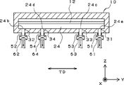
- FIG. 2 is a sectional view taken along the arrow a in FIG. 3A is a cross-sectional view taken along the arrow b in FIG. 1, and
- FIG. 3B is a plan view of the shim plate 15.
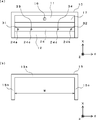
- FIG. 4A is a perspective view of the second manifold and the discharge port of the first embodiment
- FIG. 4B is a side view of the second manifold and the discharge port of the first embodiment.
- FIG. 5A is a diagram illustrating a second manifold and a discharge port according to a conventional embodiment
- FIG. 5B is a diagram illustrating a second manifold and a discharge port according to the first embodiment.
- the coating device 1 is a device for coating the coating liquid 3 on the base material 2 sent in a roll-to-roll manner.
- the coating liquid 3 is applied with a uniform thickness (uniform coating amount) along the feeding direction MD of the substrate 2.
- the width direction TD of the substrate 2 is a direction orthogonal to the feed direction MD of the substrate 2, and the Y-axis direction in FIG.
- the coating apparatus 1 includes a die 10 configured to be long along the width direction of the substrate 2, and a supply unit 20 that supplies the coating liquid 3 to the die 10.
- the longitudinal direction (the Y-axis direction in FIG. 1) is referred to as a width direction TD, which is the same as the width direction TD of the substrate 2.
- the roller 5 facing the die 10 is installed, and the width direction TD of the die 10 and the direction of the rotation center line of the roller 5 are parallel.
- the base material 2 is guided by the roller 5, and a gap (gap) between the base material 2 and the die 10 (tip of a slit 12 described later) is kept constant, and the coating of the coating liquid 3 is performed in this state. .
- the die 10 includes a first divided body 13 having a tapered first lip 13a and a second divided body 14 having a tapered second lip 14a, with a shim plate 15 interposed therebetween. It consists of a combination.
- FIG. 2 is a sectional view taken along the arrow a in FIG.
- FIG. 3A is a cross-sectional view taken along the arrow b in FIG. 1, and the shim plate 15 is shown in FIG.
- the die 10 has therein a first manifold 11 formed of a space long in the width direction TD, and a slit 12 connected to the first manifold 11, and has a first lip 13a and a second lip 14a.
- a discharge port 18 which is an open end of the slit 12 is formed between the slits. That is, the first manifold 11 and the discharge port 18 are connected via the slit 12.
- the slit 12 is formed to be long in the width direction TD similarly to the first manifold 11, and the width direction dimension of the slit 12 is determined by an inner dimension W of a shim plate 15 described later (see FIG. 3B).
- the coating liquid 3 having a width dimension substantially equal to the width dimension of the slit 12 can be applied onto the base material 2.
- the gap size (height size) of the slit 12 is, for example, 0.4 to 1.5 mm.
- the die 10 is installed in a posture in which the gap direction of the slit 12 is the vertical direction and the width direction is the horizontal direction.
- the die 10 is installed in a posture in which the first manifold 11, the second manifold 24, and the slit 12 are arranged in a horizontal direction. Therefore, the direction in which the coating liquid 3 stored in the first manifold 11 flows to the base material 2 through the slits 12 and the discharge ports 18 is horizontal.
- the pressure (coating pressure) inside the first manifold 11 can be adjusted by changing the thickness of the shim plate 15, and by this adjustment, the coating liquid 3 having various characteristics can be formed into a uniform film. Thick coating can be performed.
- the direction in which the coating liquid 3 flows to the base material 2 through the discharge port 18 is the horizontal direction, but is not necessarily limited to this, and can be appropriately changed.
- the direction may be upward or downward, and may be set in any direction.
- An inflow portion 16 is provided at the center of the die 10 in the width direction TD, and the inflow portion 16 is formed of a through-hole (inlet) connected to the first manifold 11 from outside the die 10.
- the supply means 20 supplies an inflow pipe 21 having one end connected to the inflow section 16, a tank 22 storing the coating liquid 3, and the coating liquid 3 in the tank 22 to the die 10 through the pipe 21.
- a pump 23 for supplying.
- the supply unit 20 can supply the coating liquid 3 to the first manifold 11 from the inflow portion 16.
- the inflow portion 16 is connected to the bottom portion 17 of the first manifold 11, and has a configuration in which the coating liquid 3 flows from the bottom portion 17.
- the first manifold 11 can store the coating liquid 3 supplied from the supply unit 20, and the coating liquid 3 stored in the first manifold 11 is rolled from the discharge port 18 through the slit 12. It is possible to discharge onto the base material 2 sent in a two-roll manner and to continuously apply the coating liquid 3 to the base material 2.
- the gap size of the slit 12 is designed to be constant in the width direction, and the thickness of the coating liquid 3 applied on the substrate 2 is designed to be constant in the width direction.
- the die 10 is provided with a pressure sensor (not shown), and this pressure sensor measures the internal pressure of the coating liquid 3 in the first manifold 11.
- the supply of the coating liquid 3 by the supply unit 20 is controlled based on the measurement result, and the internal pressure of the coating liquid 3 in the first manifold 11 is kept constant.
- the coating liquid 3 having a constant internal pressure in the first manifold 11 is discharged from the slit 12 in a uniform amount over the entire length in the width direction, and based on the measurement result of the pressure sensor, the coating liquid 3 is discharged from the slit 12.
- the amount of the liquid 3 is controlled so as not to fluctuate, and the thickness of the coating liquid 3 applied on the substrate 2 in the feed direction is made constant.
- a filter for the coating liquid 3 is provided in the middle of the pipe 21.
- a second manifold 24 is provided in the middle of the slit 12 between the first manifold 11 and the discharge port 18.
- the length of the second manifold 24 in the width direction TD is equal to that of the first manifold 11 and the slit 12, and the cross-sectional area in the width direction TD is smaller than that of the first manifold 11. That is, the volume is smaller than that of the first manifold 11.
- the coating liquid 3 supplied by the supply unit 20 is first stored in the first manifold 11, then the flow rate is leveled by the second manifold 24, and the discharge liquid 18 is discharged through the slit 12. Is discharged from.
- the second manifold 24 is connected to discharge ports 31, 32, 33, and 34 through which the coating liquid 3 flows out of the die 10 from a position other than the discharge port 18.
- first and second discharge ports 31 and 32 are provided at both ends 24a and 24b in the width direction of the second manifold 24 shown in FIG.
- Third and fourth discharge ports 33 and 34 are provided in the middle portions 24c and 24d between them.
- the discharge ports 31, 32, 33, and 34 include through holes that connect the second manifold 24 to the outside of the die 10, and pipes 51, 52, 53, and 54 that are connected to the through holes. One end of each of the pipes 51, 52, 53, 54 is connected to the tank 22.
- the coating liquid 3 stored in the tank 22 flows from the inflow portion 16 into the first manifold 11, and the discharge ports 31, 32, 33. , 34 can return the coating liquid 3 to the tank 22.
- the second manifold 24 is provided on both the first divided body 13 and the second divided body 14.
- the present invention is not necessarily limited to this and can be appropriately changed. is there.
- the second manifold 24 may be provided only on the first divided body 13, or the second manifold 24 may be provided only on the second divided body 14.
- the discharge ports 31, 32, 33, and 34 may be provided in the second manifold 24 provided in either the first divided body 13 or the second divided body 14.
- Each of the discharge ports 31, 32, 33, and 34 is provided with a control device for adjusting the amount of the coating liquid 3 flowing out from the slit 12. More specifically, as shown in FIG. 2, valves 61, 62, 63, and 64 are connected to the pipes 51, 52, 53, and 54, respectively, as the control device. Each of these valves 61, 62, 63, 64 has a function of adjusting the flow rate of the coating liquid 3 flowing out of each of the discharge ports 31, 32, 33, 34. Note that each of the valves 61, 62, 63, 64 may adjust the pressure of the coating liquid 3 flowing out of each of the discharge ports 31, 32, 33, 34.
- a device for example, a pump for controlling the flow rate (adjusting the outflow amount) of the coating liquid 3 is provided in the middle of the pipes 51, 52, 53, 54 connecting the discharge ports 31, 32, 33, 34 and the tank 22.
- the device functions as a control device for adjusting the discharge of the coating liquid 3 flowing out from the slit 12.
- the coating apparatus 1 also includes a sensor 36 for measuring the thickness of the coating liquid 3 applied on the substrate 2 (see FIG. 1).
- a plurality of sensors 36 may be provided along the width direction.
- the sensor 36 is a non-contact type and can measure the film thickness of the coating liquid 3 on the substrate 2 at a plurality of locations along the width direction or over the entire length in the width direction TD.
- the data is output to a control device (computer) 37 provided in the device 1.
- the control device 37 performs feedback control based on the measurement result from the sensor 36, and adjusts the opening degrees of the valves 61, 62, 63, and 64.
- control device 37 outputs a control signal to each of the valves 61, 62, 63, 64 according to the measurement result of the film thickness of the coating liquid 3, and the opening degree of each of the valves 61, 62, 63, 64. To adjust. This makes it possible to keep the film thickness of the coating liquid 3 constant in the width direction.
- the opening degree of the valves 61, 62, 63, 64 may be controlled by a timer function of the control device 37 instead of the sensor 36. That is, since precipitation and agglomeration of the solid components of the coating liquid 3 become a problem when a certain time elapses from the start of application, a predetermined time before this time elapses is measured by a timer, and when the predetermined time elapses, the control is performed.
- the device 37 may positively control the opening degrees of the valves 61, 62, 63, 64.
- the second manifold 24 on the side to which the discharge ports 31, 32, 33, and 34 are connected has a semi-cylindrical portion whose semicircle is continuous in the width direction TD (Y-axis direction).
- the end (end Z in FIG. 4A) of the semi-cylindrical portion 25 in a direction (Z-axis direction) orthogonal to the width direction TD is separated from the slit 12.
- the second manifold 24 on the side to which the discharge ports 31, 32, 33, 34 are connected has a configuration in which a rectangular parallelepiped portion 26 long in the width direction TD is added between the semi-cylindrical portion 25 and the slit 12. Have been.
- the cross section of each of the discharge ports 31, 32, 33, and 34 has a cylindrical shape. 3 is provided at right angles to the flowing direction (X-axis direction).
- the discharge ports 31, 32, 33, and 34 having a cylindrical cross section are connected to the arc portion of the semi-cylindrical portion 25 of the second manifold 24, the second manifold 24 and the discharge ports 31 and 32 are connected. , 33, 34, the inner wall surfaces are not connected smoothly, and as shown in FIGS. 4 (a) and 4 (b), the discharge ports 31, 32, 33, 34 and the second manifold 24 A curve is formed on the inner wall portion of the connection portion of the above.
- this line is referred to as a ridge line F, and a point closest to the slit 12 in the ridge line F at each connection portion is a point of closest approach P (FIGS. 4B, 5A, and 5B).
- the second manifold 24 on the side to which the discharge ports 31, 32, 33, and 34 are connected is formed only of a semi-cylindrical portion, and the diameter of the second manifold 24 and the diameter of the discharge ports 31, 32, 33, and 34 are reduced. If they are the same, the edge line F closest to the slit 12 (the point of closest approach P) can be formed on the virtual line of the slit 12 (see FIG. 5A).
- FIG. 5A shows a connection portion between the discharge port 32 and the second manifold 24, but the same applies to connection portions between the other discharge ports 31, 33, and 34 and the second manifold 24. is there.
- the ridgeline F is closest to the slit 12 (ie, the point of closest approach P) in the portion near the center in the cross section (YZ cross section) of the discharge ports 31, 32, 33, 34, and passes through the slit 12 through the discharge port 18. Fluctuation of the flow velocity occurs locally in the coating liquid 3 flowing toward. When such local fluctuations in the flow velocity occur in the discharge ports 31, 32, 33, and 34, the coating film formed on the base material 2 has the feed direction at the position in the width direction TD of the discharge port. Long coating streaks may occur on the MD.
- the ridgeline F formed on the inner wall of the connection portion between the discharge ports 31, 32, 33, 34 and the second manifold 24 is configured to be separated from the slit 12.
- the second manifold 24 on the side to which the discharge ports 31, 32, 33, and 34 are connected has a configuration in which a rectangular parallelepiped portion is added between the semi-cylindrical portion and the slit 12. ing.
- FIG. 5B shows a connection portion between the discharge port 32 and the second manifold 24, the same applies to connection portions between the other discharge ports 31, 33, and 34 and the second manifold 24. is there.
- a point of closest approach P can be defined as an intersection with the slit 12, and a local variation in the flow velocity at the point of closest approach P causes a film in the width direction TD of the coating liquid 3 to be discharged from the discharge port 18 through the slit 12. It affects the thickness distribution and may cause coating streaks on the coating film as described above.
- the discharge ports 31, 32, 33, and 34 provided orthogonal to the arc portion on the opposite side to the slit 12 of the semi-cylindrical portion of the second manifold 24 and the second manifold 24. Since the ridgeline F formed on the inner wall portion of the connection portion with the manifold 24 is configured to be separated from the slit 12, even if local flow velocity fluctuation occurs near the ridgeline F, it is generated on the base material 2. Influence on the formed coating film can be suppressed, and a coating film free of coating streaks can be applied.
- the number of discharge ports is four, but the number is not limited to four and can be changed as appropriate.
- the number may be two or three, or five or more, and may be an arbitrary number depending on the length of the die 10 in the width direction TD and the strictness of film thickness management.
- a portion to be added between the semi-cylindrical portion and the slit 12 is not limited to a rectangular parallelepiped, and may be, for example, a quadrangular prism having a trapezoidal shape continuous in the width direction TD.
- the second manifold 24 is configured such that the semicircle has a hollow shape of a semi-cylindrical column that is continuous in the width direction TD, but the present invention is not necessarily limited to this and can be appropriately changed.
- the cross-sectional area of the second manifold 24 in the direction orthogonal to the width direction TD is smaller than that of the first manifold 11 and the volume is smaller than that of the first manifold 11.
- the present invention is not limited to this, and can be appropriately changed.
- the cross-sectional area of the second manifold 24 in a direction orthogonal to the width direction TD may be larger than the first manifold 11 and may have a larger volume than the first manifold 11.
- the first manifold that is a space that is long in the width direction and stores the coating liquid
- the first manifold is connected to the first manifold through the slit that is wide in the width direction, and the coating liquid is supplied to the base material.
- a second manifold provided in the slit in the width direction between the first manifold and the discharge port, and a plurality of the second manifolds provided in the width direction in the second manifold.
- a coating film having local flow rate fluctuation is provided by a coating device, wherein a ridgeline formed on an inner wall portion of a connection portion between a discharge port and the second manifold is separated from the slit. Against impact and suppress the can coating the generated no coating film of the coating streaks.
- the coating liquid stored in the first manifold that is long in the width direction formed on the die is applied to the base material from the discharge port connected to the first manifold through the slit that is wide in the width direction.
- a second manifold long in the width direction is provided in the slit between the first manifold and the discharge port, and a plurality of coating liquids are discharged from the second manifold.
- the ridge line formed on the inner wall portion of the connection portion between the discharge port and the second manifold is separated from the slit, thereby suppressing the influence of the disturbance of the flow of the coating liquid on the ridge line on the coating film.
- FIGS. 6A and 6B Modifications of the first embodiment are shown in FIGS. 6A and 6B. Although this modified example will be described using the discharge port 32 as an example, the same applies to the discharge ports 31, 33, and 34.
- FIG. 6A illustrates the discontinuous point P when the diameter of the second manifold 24 is large.
- the point of closest approach P is the dimension L in FIG.
- the inlet (the opening on the slit side) of the discharge port 32 is formed at a position separated from the slit 12, and the vicinity of the ridge formed on the inner wall of the connection portion between the discharge port 32 and the second manifold 24 is formed.
- the influence of the local flow rate fluctuation on the coating film can be suppressed, and a coating film free from coating streaks can be applied to the base material 2. That is, in the modification shown in FIG. 6A, since the radius of the second manifold 24 is large, a rectangular parallelepiped portion is not added between the semi-cylindrical portion and the slit 12 as in the first embodiment. The closest point P is configured to be separated from the slit 12.
- FIG. 6A is a case where the diameter of the semi-cylindrical portion of the second manifold 24 is larger than the diameter of the cylindrical shape of the discharge port 32.
- the diameter of the semi-cylindrical portion of the second manifold 24 may be smaller than the diameter of the cylindrical shape of the discharge port 32.
- the discharge port 32 does not penetrate to the slit 12 and intersects only a part of the semi-cylindrical portion of the second manifold 24, the closest approach as shown by the dimension L in FIG. The point P and the slit 12 are separated.
- the discharge port 32 does not necessarily need to extend in the direction (Z-axis direction) orthogonal to the direction in which the coating liquid flows (X-axis direction) in the slit 12, and the point of closest approach P is The discharge port 32 may extend obliquely to the direction in which the coating liquid flows in the slit 12 as long as the discharge port 32 is separated from the slit 12.
- the ridge formed on the inner wall of the connection portion between the discharge port and the second manifold does not necessarily have to be sharp, and may be slightly rounded. Even in such a case, since the flow of the coating liquid at the ridgeline may be disturbed, the coating apparatus and the coating method of the present invention can solve the problem of the generation of the coating streak.
- the present invention can be widely applied to a coating apparatus and a coating method for coating a substrate with a coating liquid.
Landscapes
- Engineering & Computer Science (AREA)
- Manufacturing & Machinery (AREA)
- Chemical & Material Sciences (AREA)
- Chemical Kinetics & Catalysis (AREA)
- Electrochemistry (AREA)
- General Chemical & Material Sciences (AREA)
- Coating Apparatus (AREA)
- Application Of Or Painting With Fluid Materials (AREA)
- Battery Electrode And Active Subsutance (AREA)
Abstract
塗工スジが発生しない塗工膜を塗工することが可能な塗工装置および塗工方法を提供する。具体的には、幅方向に長く塗液を溜める空間からなる第1のマニホールド11と、当該幅方向に広いスリット12を経由して第1のマニホールド11と繋がり、塗液3を基材2に対して吐出する吐出口18と、第1のマニホールド11と吐出口18との間のスリット12に前記幅方向に設けられた第2のマニホールド24と、第2のマニホールド24において前記幅方向に複数設けられた塗液3を排出させる排出ポート31乃至34と、が形成されたダイ10と、第1のマニホールド11に連通している流入部16から第1のマニホールド11に塗液3を供給する供給手段20と、を備え、排出ポート31乃至34と第2のマニホールド24との接続部位の内壁部に形成される稜線Fが、スリット12から離間している。
Description
本発明は、基材に塗工膜を塗工する塗工装置、及び塗工方法に関するものである。
ロールツーロールで送られる基材に、塗工液をダイの吐出口から塗工して電池の極板等を製造することが行われている。基材上に形成される塗工層の厚さは、例えば電池の場合、電池の充放電量に直接影響を与えることから、基材に塗工する塗工液の膜厚管理は非常に重要となる。つまり、塗工液は、基材の幅方向及び送り方向に沿って均一な厚さで塗工される必要がある。
特許文献1には、排出ポート(調整部)を設けることにより、塗工液の吐出作業を長時間継続して行っていても、基材上に形成される塗膜層の厚さを均一にする構成が記載されている。
特許文献1:特開2015-97198号公報
しかしながら、特許文献1記載の塗工装置では、塗液をダイからタンクに戻す排出ポートとスリットとの接続部位ではその内壁部に形成される稜線によって塗工液の流れに乱れが生じ、それが基材へ向かって吐出される塗工液の流れにも影響する可能性があり、その場合、排出ポートの存在する幅方向の位置において塗工面に塗工スジが発生するという問題があった。
本発明は、上記問題点を鑑みてなされたものであり、塗工スジの発生しない塗工膜を塗工することが可能な塗工装置および塗工方法を提供することを目的としている。
上記の課題を解決するために本発明の塗工装置は、幅方向に長く塗液を溜める空間からなる第1のマニホールドと、当該幅方向に広いスリットを経由して当該第1のマニホールドと繋がり、塗液を基材に対して吐出する吐出口と、前記第1のマニホールドと前記吐出口との間の前記スリットに前記幅方向に設けられた第2のマニホールドと、前記第2のマニホールドにおいて前記幅方向に複数設けられた塗液を排出させる排出ポートと、が形成されたダイと、前記第1のマニホールドに連通している流入部から前記第1のマニホールドに塗液を供給する供給手段と、を備え、前記排出ポートと前記第2のマニホールドとの接続部位の内壁部に形成される稜線が、前記スリットから離間していることを特徴としている。
上記塗工装置によれば、排出ポートと第2のマニホールドとの接続部位の内壁部に形成される稜線が、スリットから離間していることにより、吐出口から吐出される塗液の流れは、排出ポートの接続部位の稜線による塗液の流れの乱れの影響を受けにくくなるため、塗工スジの発生しない塗工膜を塗工することができる。
また、前記第2のマニホールドは、半円が前記幅方向に連続する半円柱状部を含み、前記半円柱状部における前記幅方向と直交する方向の端部が前記スリットから離間することにより、前記稜線が前記スリットから離間していてもよい。
この構成により、第2のマニホールドにおける半円柱状部のスリットと反対側に位置する円弧部分に接続された排出ポートの入口をスリットから離せるため、排出ポートの入口部分に形成される稜線における塗液の流れの乱れの塗工膜に対する影響を抑制し、塗工スジの発生しない塗工膜を塗工することができる。
また、上記の課題を解決するために本発明の塗工方法は、ダイに形成された幅方向に長い第1のマニホールドに溜められている塗液を、当該幅方向に広いスリットを経由して当該第1のマニホールドと繋がる吐出口から基材に塗工して行う塗工方法であって、前記第1のマニホールドと前記吐出口との間の前記スリットに前記幅方向に長い第2のマニホールドが設けられ、当該第2のマニホールドから塗液を排出させる複数の排出ポートと前記第2のマニホールドとの接続部位の内壁部に形成される稜線が、前記スリットから離間していることにより、前記稜線における塗液の流れの乱れの塗工膜に対する影響を抑制することを特徴としている。
この構成により、局所的な流速変動の塗工膜に対する影響を抑制し、塗工スジの発生しない塗工膜を塗工することができる。
本発明の塗工装置および塗工方法によれば、塗工スジの発生しない塗工膜を塗工することができる。
本発明の実施例1について、図1~図5を参照して説明する。図1は、本発明の実施例1における塗工装置の概略構成を説明する図である。図2は、図1のa矢視の断面図である。図3は、(a)は、図1のb矢視の断面図であり、(b)は、シム板15の平面図である。図4は、(a)は、実施例1の第2のマニホールドおよび排出ポートの斜視図であり、(b)は、実施例1の第2のマニホールドおよび排出ポートの側面図である。図5は、(a)は、従来の実施形態の第2のマニホールドおよび排出ポートを説明する図、(b)は、実施例1における第2のマニホールドおよび排出ポートを説明する図である。
塗工装置1は、ロールツーロールで送られる基材2に、塗液3を塗工するための装置である。塗液3は、基材2の送り方向MDに沿って均一な厚さ(均一な塗工量)で塗工される。なお、基材2の幅方向TDは、基材2の送り方向MDに直交する方向であり、図1におけるY軸方向がこれに相当する。
塗工装置1は、基材2の幅方向に沿って長く構成されたダイ10と、このダイ10に塗液3を供給する供給手段20とを備えている。ダイ10において、その長手方向(図1におけるY軸方向)を幅方向TDといい、基材2の幅方向TDと同じである。この塗工装置1では、ダイ10に対向するローラ5が設置されており、ダイ10の幅方向TDとローラ5の回転中心線の方向とは平行である。基材2は、このローラ5に案内され、基材2とダイ10(後述のスリット12の先端)との間隔(隙間)が一定に保たれ、この状態で塗液3の塗工が行われる。
ダイ10は、先細り形状である第一リップ13aを有する第一分割体13と、先細り形状である第二リップ14aを有する第二分割体14とを、これらの間にシム板15を挟んで、組み合わせた構成からなる。図2は、図1のa矢視の断面図である。図3(a)は、図1のb矢視の断面図であり、シム板15を、図3(b)に示している。ダイ10は、その内部に、幅方向TDに長い空間からなる第1のマニホールド11と、この第1のマニホールド11と繋がるスリット12とが形成され、また、第一リップ13aと第二リップ14aとの間には、スリット12の解放端である吐出口18が形成されている。すなわち、第1のマニホールド11と吐出口18とは、スリット12を経由して繋がっている。
スリット12は、第1のマニホールド11と同様に幅方向TDに長く形成されており、スリット12の幅方向寸法は、後述するシム板15の内寸W(図3(b)参照)によって決定され、スリット12の幅方向寸法と略同一の幅方向寸法の塗液3を、基材2上に塗工することができる。スリット12の隙間寸法(高さ寸法)は、例えば0.4~1.5mmである。実施例1では、スリット12の隙間方向が上下方向であり、幅方向が水平方向となる姿勢でダイ10は設置されている。つまり、第1のマニホールド11及び第2のマニホールド24とスリット12とが水平方向に並んで配置される姿勢でダイ10は設置されている。したがって、第1のマニホールド11に溜められている塗液3をスリット12および吐出口18を通じて基材2へと流す方向は水平方向となる。
なお、シム板15の厚さを変更することにより、第1のマニホールド11内部の圧力(塗工圧力)を調整することができ、この調整によって、様々な特性を有する塗液3を均一な膜厚の塗工を行うことが可能となる。
また、実施例1においては、塗液3が吐出口18を通じて基材2へと流れる方向を水平方向としたが、必ずしもこれに限定されず適宜変更が可能である。例えば、上方向としてもよいし、下方向としてもよく、任意の方向に設定することができる。
ダイ10の幅方向TDの中央部には、流入部16が設けられており、この流入部16は、ダイ10の外部から第1のマニホールド11へ繋がる貫通孔(流入口)からなる。供給手段20は、この流入部16に一端部が接続されている流入パイプ21と、塗液3を貯留しているタンク22と、このタンク22内の塗液3を、パイプ21を通じてダイ10へ供給するためのポンプ23とを有している。以上より、供給手段20は、第1のマニホールド11に流入部16から塗液3を供給することができる。なお、実施例1では、図1に示すように、流入部16は、第1のマニホールド11の底部17と繋がっており、この底部17から塗液3を流入させる構成としている。
そして、第1のマニホールド11は、供給手段20から供給された塗液3を溜めることができ、第1のマニホールド11に溜められている塗液3を、スリット12を通って吐出口18からロールツーロールで送られる基材2に対して吐出し、この基材2に対して塗液3を連続的に塗工することができる。スリット12の隙間寸法はその幅方向に一定であり、基材2上に塗工される塗液3の厚さは幅方向に一定となるよう設計されている。
また、ダイ10には圧力センサ(図示せず)が設けられており、この圧力センサは、第1のマニホールド11の塗液3の内圧を計測する。そして、この計測結果に基づいて供給手段20による塗液3の供給が制御され、第1のマニホールド11の塗液3の内圧を一定に保つ。第1のマニホールド11で内圧が一定とされる塗液3は、スリット12から幅方向全長にわたって均等の量で吐出され、また、前記圧力センサの計測結果に基づいて、スリット12から吐出される塗液3の量が変動しないように制御され、基材2上に塗工される塗液3の送り方向の厚さを一定とする。また、図示しないが、パイプ21の途中には塗液3用のフィルタが設けられている。
ここで、第1のマニホールド11と吐出口18の間であるスリット12の途中には、第2のマニホールド24が設けられている。第2のマニホールド24の幅方向TDの長さは第1のマニホールド11およびスリット12と同等であり、幅方向TDの断面積は第1のマニホールド11よりも小さい。すなわち、第1のマニホールド11よりも容積が小さい。
この構成により、供給手段20により供給された塗液3は、先ず第1のマニホールド11に溜められ、次に、第2のマニホールド24で流量を平準化され、スリット12を経由して吐出口18から吐出される。
また、図2に示すように、第2のマニホールド24には、塗液3を吐出口18以外からダイ10の外部へ流出させる排出ポート31,32,33,34が接続されている。実施例1では、図3(a)に示す第2のマニホールド24の幅方向の両端部24a,24bに、第1と第2の排出ポート31,32が設けられ、この両端部24a,24bの間の途中部24c,24dに、第3と第4の排出ポート33,34が設けられている。基材2への塗液3の塗工中にこれら排出ポート31,32,33,34から塗液3を排出することにより、幅方向TDにおける吐出口18からの塗液の吐出量分布が調整される。
排出ポート31,32,33,34は、第2のマニホールド24とダイ10の外部とを繋ぐ貫通孔と、その貫通孔に接続されている配管51,52,53,54とからなる。配管51,52,53,54の一端はタンク22に繋がれており、タンク22に貯留される塗液3を流入部16から第1のマニホールド11に流入させるとともに、排出ポート31,32,33,34から塗液3をタンク22に戻すことができる。
なお、実施例1においては、図1に示すように、第一分割体13及び第二分割体14の双方に第2のマニホールド24を設けたが、必ずしもこれに限定されず適宜変更が可能である。例えば、第一分割体13のみに第2のマニホールド24を設けてもよいし、第二分割体14にのみ第2のマニホールド24を設けてもよい。また、このとき排出ポート31,32,33,34は、第一分割体13又は第二分割体14のいずれかに設けられた第2のマニホールド24に設ければよい。
排出ポート31,32,33,34それぞれには、スリット12から流出させる塗液3の量の調整を行う制御装置が設けられている。具体的に説明すると、図2に示すように、配管51,52,53,54それぞれに、前記制御装置としてバルブ61,62,63,64が接続されている。これらバルブ61,62,63,64それぞれは、排出ポート31,32,33,34それぞれから流出する塗液3の流量を調整する機能を有している。なお、バルブ61,62,63,64それぞれは、排出ポート31,32,33,34それぞれから流出する塗液3の圧力を調整してもよい。または、排出ポート31,32,33,34とタンク22とを繋ぐ配管51,52,53,54の途中に、塗液3の流量管理(流出量調整)を行う機器(例えば、ポンプ)が設けられていてもよく、この場合、この機器が、スリット12から流出させる塗液3の排出調整を行う制御装置として機能する。
また、この塗工装置1は、基材2上へ塗工した塗液3の膜厚を測定するセンサ36を備えている(図1参照)。センサ36は、幅方向に沿って複数設けられていてもよい。センサ36は、非接触式であり、基材2上の塗液3の膜厚を、幅方向に沿って複数カ所、又は、幅方向TDの全長にわたって計測可能であり、計測結果は、塗工装置1が備えている制御装置(コンピュータ)37に出力される。制御装置37はセンサ36からの計測結果に基づくフィードバック制御を行い、バルブ61,62,63,64の開度を調整する。つまり、塗液3の膜厚の計測結果に応じて、制御装置37は、バルブ61,62,63,64それぞれに対して制御信号を出力し、バルブ61,62,63,64それぞれの開度を調整する。これにより、塗液3の膜厚を幅方向に一定に保つことが可能となる。
なお、センサ36の代わりに制御装置37が有するタイマ機能により、バルブ61,62,63,64の開度を制御してもよい。つまり、塗布開始からある時間が経過すると塗液3の固形成分の沈殿や凝集が問題となることから、この時間が経過する前の所定時間をタイマで計測し、その所定時間が経過すると、制御装置37はバルブ61,62,63,64の開度を積極的に制御してもよい。
次に、第2のマニホールド24と排出ポート31,32,33,34の接続部位について詳しく説明する。図4(a)に示すように、排出ポート31,32,33,34が接続される側の第2のマニホールド24は、半円が幅方向TD(Y軸方向)に連続する半円柱状部25を含み、この半円柱状部25における幅方向TDと直交する方向(Z軸方向)の端部(図4(a)における端部Z)がスリット12から離間している。つまり、排出ポート31,32,33,34が接続される側の第2のマニホールド24は、半円柱状部25とスリット12との間に幅方向TDに長い直方体状部26を継ぎ足した構成とされている。そして、排出ポート31,32,33,34の断面は円筒形状であり、その開口端部は第2のマニホールド24の半円柱状部25のスリット12と反対側の円弧部分にスリット12を塗液3が流れる方向(X軸方向)と直交して設けられている。
ここで、断面円筒状の排出ポート31,32,33,34は、第2のマニホールド24の半円柱状部25の円弧部分に接続されているため、第2のマニホールド24と排出ポート31,32,33,34との接続部位では内壁面同士が滑らかに接続されず、図4(a)および図4(b)に示すように排出ポート31,32,33,34と第2のマニホールド24との接続部位の内壁部に曲線が形成される。本説明では、この線を稜線Fと呼び、各接続部位における稜線Fの中で最もスリット12に近い点を最接近点P(図4(b)、図5(a)および図5(b)に●で示す)と呼ぶ。仮に、排出ポート31,32,33,34が接続される側の第2のマニホールド24が半円柱状部のみで形成され、第2のマニホールド24と排出ポート31,32,33,34の径が同じであれば、稜線Fのうち最もスリット12に近接するもの(最接近点P)はスリット12の仮想線上にできる(図5(a)参照)。なお、図5(a)は排出ポート32と第2のマニホールド24との接続箇所を示しているが、他の排出ポート31,33,34と第2のマニホールド24との接続部位についても同様である。
そして、稜線Fの近傍では、壁面の形状が滑らかでないため塗液3の流れに乱れが生じる。特に、排出ポート31,32,33,34の断面(YZ断面)における中心に近い部分では稜線Fがスリット12に最も接近しており(すなわち最接近点P)、スリット12を通って吐出口18へ向かう塗液3において局所的な流速の変動が起こる。このような、局所的な流速の変動が排出ポート31,32,33,34において起こると、基材2に形成される塗工膜には、当該排出ポートの幅方向TDにおける位置において、送り方向MDに長く塗工スジが発生することがある。
そのため、実施例1においては、排出ポート31,32,33,34と第2のマニホールド24との接続部位における局所的な流速の変動が生じてもその影響が塗工膜に及ばないように、排出ポート31,32,33,34と第2のマニホールド24との接続部位の内壁部に形成される稜線Fがスリット12から離間するように構成されている。具体的には、前述の通り排出ポート31,32,33,34が接続される側の第2のマニホールド24は、半円柱状部とスリット12との間に直方体状部を継ぎ足した構成とされている。
詳しく説明すると、図5(b)に示す通り、第2のマニホールド24と排出ポート31,32,33,34の径が同じであっても、深さLの直方体状部が継ぎ足された構成であることにより、最接近点Pがスリット12から離間するようになっている。なお、図5(b)は排出ポート32と第2のマニホールド24との接続部位を示しているが、他の排出ポート31,33,34と第2のマニホールド24との接続部位についても同様である。
仮に、この半円柱状部への直方体状部の継ぎ足しがなく、図5(a)に示すように、第2のマニホールド24の直径と排出ポート31,32,33,34の直径が同じ寸法なら、最接近点Pは、スリット12との交点にでき、この最接近点Pにおける局所的な流速の変動がスリット12を経由して吐出口18から吐出される塗液3の幅方向TDの膜厚分布に影響し、上記のとおり塗膜に塗工スジが発生するおそれがある。
これに対し、実施例1の形態では、第2のマニホールド24の半円柱状部のスリット12と反対側の円弧部分に直交して設けられた排出ポート31,32,33,34と第2のマニホールド24との接続部位の内壁部に形成される稜線Fがスリット12から離間するように構成されているため、稜線Fの近傍において局所的な流速変動が生じたとしてもそれが基材2に形成される塗工膜に対して影響することを抑制し、塗工スジの発生しない塗工膜を塗工することができる。
なお、実施例1においては、排出ポートの数を4個としたが、必ずしもこれに限定されず適宜変更が可能である。例えば、2個又は3個としてもよいし、5個以上としてもよく、ダイ10の幅方向TDの長さや膜厚管理の厳密さによって任意の数とすることができる。
また、半円柱状部とスリット12との間を継ぎ足す部位は、直方体状には限らず、たとえば台形が幅方向TDに連続する四角柱状でも良い。
さらに、実施例1においては、第2のマニホールド24は半円が幅方向TDに連続する半円柱の中空形状を有するように構成したが、必ずしもこれに限定されず適宜変更が可能である。例えば、多角形が幅方向TDに連続する多角柱の中空形状を有するように構成してもよい。
また、実施例1においては、第2のマニホールド24における幅方向TDに直交する方向の断面積は第1のマニホールド11よりも小さく、第1のマニホールド11よりも容積を小さく構成したが、必ずしもこれに限定されず適宜変更が可能である。例えば、第2のマニホールド24における幅方向TDに直交する方向の断面積は第1のマニホールド11よりも大きく、第1のマニホールド11よりも容積が大きい構成としてもよい。
このように、実施例1においては、幅方向に長く塗液を溜める空間からなる第1のマニホールドと、当該幅方向に広いスリットを経由して当該第1のマニホールドと繋がり、塗液を基材に対して吐出する吐出口と、前記第1のマニホールドと前記吐出口との間の前記スリットに前記幅方向に設けられた第2のマニホールドと、前記第2のマニホールドにおいて前記幅方向に複数設けられた塗液を排出させる排出ポートと、が形成されたダイと、前記第1のマニホールドに連通している流入部から前記第1のマニホールドに塗液を供給する供給手段と、を備え、前記排出ポートと前記第2のマニホールドとの接続部位の内壁部に形成される稜線が、前記スリットから離間していることを特徴とする塗工装置により、局所的な流速変動の塗工膜に対する影響を抑制し、塗工スジの発生しない塗工膜を塗工することができる。
また、ダイに形成された幅方向に長い第1のマニホールドに溜められている塗液を、当該幅方向に広いスリットを経由して当該第1のマニホールドと繋がる吐出口から基材に塗工して行う塗工方法であって、前記第1のマニホールドと前記吐出口との間の前記スリットに前記幅方向に長い第2のマニホールドが設けられ、当該第2のマニホールドから塗液を排出させる複数の排出ポートと前記第2のマニホールドとの接続部位の内壁部に形成される稜線が、前記スリットから離間していることにより、前記稜線における塗液の流れの乱れの塗工膜に対する影響を抑制することを特徴とする塗工方法により、塗工スジの発生しない塗工膜を塗工することができる。
(変形例)
実施例1における変形例を、図6(a)および図6(b)に示す。この変形例についても排出ポート32を例にとって説明するが、排出ポート31,33,34についても同様である。
実施例1における変形例を、図6(a)および図6(b)に示す。この変形例についても排出ポート32を例にとって説明するが、排出ポート31,33,34についても同様である。
図6(a)では、第2のマニホールド24の径が大きい場合の不連続点Pについて説明する。図6(a)に示すように、排出ポート32の円筒形状の径に比べて第2のマニホールド24の半円柱状部の径が大きい場合、最接近点Pは図6(a)に寸法Lで示すようにスリット12より離間した位置に形成される。つまり、排出ポート32の入口(スリット側の開口部)は、スリット12から離間した位置に形成されることになり、排出ポート32と第2のマニホールド24の接続部位の内壁に形成される稜線近傍における局所的な流速変動の塗工膜に対する影響を抑制し、塗工スジの発生しない塗工膜を基材2に塗工することができる。つまり、図6(a)に示す変形例においては、第2のマニホールド24の半径が大きいため、上記実施例1のように半円柱状部とスリット12の間に直方体部を継ぎ足すことなく、最接近点Pがスリット12から離間するように構成される。
ここで、図6(a)の例は排出ポート32の円筒形状の径に比べて第2のマニホールド24の半円柱状部の径が大きい場合であるが、図6(b)のように、排出ポート32の円筒形状の径に比べて第2のマニホールド24の半円柱状部の径が小さくても良い。この場合、排出ポート32がスリット12まで貫通せず、第2のマニホールド24の半円柱状部の一部とのみ交差する形態であることにより、図6(b)に寸法Lで示す通り最接近点Pとスリット12が離間する。
なお、これら変形例以外であっても、本発明の範囲内において他の形態のものであってもよい。たとえば、図7に示すように、排出ポート32は必ずしもスリット12内で塗液が流れる方向(X軸方向)と直交する方向(Z軸方向)に延びている必要は無く、最接近点Pがスリット12から離間してさえすれば、スリット12内で塗液が流れる方向に対して排出ポート32が斜めの方向に延びていても良い。
また、排出ポートと前記第2のマニホールドとの接続部位の内壁部に形成される稜線は必ずしも尖っている必要は無く、少々丸まっていても良い。このような場合でも、稜線における塗液の流れの乱れは生じうるため、本発明の塗工装置および塗工方法が塗工スジ発生の課題を解決することができる。
本発明は、基材に塗液を塗工する塗工装置及び塗工方法に幅広く適用することができる。
1 塗工装置
2 基材
3 塗液
5 ローラ
10 ダイ
11 第1のマニホールド
12 スリット
16 流入部
17 底部
18 吐出口
20 供給手段
22 タンク
23 ポンプ
24 第2のマニホールド
25 半円柱状部
26 直方体状部
31 排出ポート
32 排出ポート
33 排出ポート
34 排出ポート
36 センサ
37 制御装置
61 バルブ
62 バルブ
63 バルブ
64 バルブ
F 稜線
P 最接近点
Z 端部
2 基材
3 塗液
5 ローラ
10 ダイ
11 第1のマニホールド
12 スリット
16 流入部
17 底部
18 吐出口
20 供給手段
22 タンク
23 ポンプ
24 第2のマニホールド
25 半円柱状部
26 直方体状部
31 排出ポート
32 排出ポート
33 排出ポート
34 排出ポート
36 センサ
37 制御装置
61 バルブ
62 バルブ
63 バルブ
64 バルブ
F 稜線
P 最接近点
Z 端部
Claims (3)
- 幅方向に長く塗液を溜める空間からなる第1のマニホールドと、当該幅方向に広いスリットを経由して当該第1のマニホールドと繋がり、塗液を基材に対して吐出する吐出口と、前記第1のマニホールドと前記吐出口との間の前記スリットに前記幅方向に設けられた第2のマニホールドと、前記第2のマニホールドにおいて前記幅方向に複数設けられた塗液を排出させる排出ポートと、が形成されたダイと、
前記第1のマニホールドに連通している流入部から前記第1のマニホールドに塗液を供給する供給手段と、を備え、
前記排出ポートと前記第2のマニホールドとの接続部位の内壁部に形成される稜線が、前記スリットから離間していることを特徴とする、塗工装置。 - 前記第2のマニホールドは、半円が前記幅方向に連続する半円柱状部を含み、前記半円柱状部における前記幅方向と直交する方向の端部が前記スリットから離間することにより、前記稜線が前記スリットから離間していることを特徴とする、請求項1に記載の塗工装置。
- ダイに形成された幅方向に長い第1のマニホールドに溜められている塗液を、当該幅方向に広いスリットを経由して当該第1のマニホールドと繋がる吐出口から基材に塗工して行う塗工方法であって、
前記第1のマニホールドと前記吐出口との間の前記スリットに前記幅方向に長い第2のマニホールドが設けられ、当該第2のマニホールドから塗液を排出させる複数の排出ポートと前記第2のマニホールドとの接続部位の内壁部に形成される稜線が、前記スリットから離間していることにより、前記稜線における塗液の流れの乱れの塗工膜に対する影響を抑制することを特徴とする、塗工方法。
Applications Claiming Priority (2)
| Application Number | Priority Date | Filing Date | Title |
|---|---|---|---|
| JP2018-160950 | 2018-08-30 | ||
| JP2018160950A JP2020032361A (ja) | 2018-08-30 | 2018-08-30 | 塗工装置及び塗工方法 |
Publications (1)
| Publication Number | Publication Date |
|---|---|
| WO2020045308A1 true WO2020045308A1 (ja) | 2020-03-05 |
Family
ID=69644361
Family Applications (1)
| Application Number | Title | Priority Date | Filing Date |
|---|---|---|---|
| PCT/JP2019/033160 Ceased WO2020045308A1 (ja) | 2018-08-30 | 2019-08-23 | 塗工装置及び塗工方法 |
Country Status (2)
| Country | Link |
|---|---|
| JP (1) | JP2020032361A (ja) |
| WO (1) | WO2020045308A1 (ja) |
Families Citing this family (2)
| Publication number | Priority date | Publication date | Assignee | Title |
|---|---|---|---|---|
| JP7398347B2 (ja) * | 2020-09-01 | 2023-12-14 | 東レエンジニアリング株式会社 | 塗工装置 |
| CN114733720B (zh) * | 2022-05-06 | 2023-03-21 | 武汉楚能新能源有限公司 | 一种狭缝式涂布机模头 |
Citations (5)
| Publication number | Priority date | Publication date | Assignee | Title |
|---|---|---|---|---|
| JPH10286508A (ja) * | 1997-04-11 | 1998-10-27 | Sony Corp | 塗布装置及び塗布方法 |
| JP2015153527A (ja) * | 2014-02-12 | 2015-08-24 | 東レエンジニアリング株式会社 | 電池用極板の製造装置 |
| WO2015141391A1 (ja) * | 2014-03-17 | 2015-09-24 | 東レエンジニアリング株式会社 | 電池用極板の製造装置 |
| JP2016033884A (ja) * | 2014-07-31 | 2016-03-10 | 東レエンジニアリング株式会社 | 電池用極板の製造装置 |
| JP2018037206A (ja) * | 2016-08-30 | 2018-03-08 | 東レエンジニアリング株式会社 | 電池用極板の製造装置及びその保守方法 |
-
2018
- 2018-08-30 JP JP2018160950A patent/JP2020032361A/ja active Pending
-
2019
- 2019-08-23 WO PCT/JP2019/033160 patent/WO2020045308A1/ja not_active Ceased
Patent Citations (5)
| Publication number | Priority date | Publication date | Assignee | Title |
|---|---|---|---|---|
| JPH10286508A (ja) * | 1997-04-11 | 1998-10-27 | Sony Corp | 塗布装置及び塗布方法 |
| JP2015153527A (ja) * | 2014-02-12 | 2015-08-24 | 東レエンジニアリング株式会社 | 電池用極板の製造装置 |
| WO2015141391A1 (ja) * | 2014-03-17 | 2015-09-24 | 東レエンジニアリング株式会社 | 電池用極板の製造装置 |
| JP2016033884A (ja) * | 2014-07-31 | 2016-03-10 | 東レエンジニアリング株式会社 | 電池用極板の製造装置 |
| JP2018037206A (ja) * | 2016-08-30 | 2018-03-08 | 東レエンジニアリング株式会社 | 電池用極板の製造装置及びその保守方法 |
Also Published As
| Publication number | Publication date |
|---|---|
| JP2020032361A (ja) | 2020-03-05 |
Similar Documents
| Publication | Publication Date | Title |
|---|---|---|
| JP6280383B2 (ja) | 電池用極板の製造装置 | |
| JP7208798B2 (ja) | 電池用極板の製造装置および電池用極板の製造方法 | |
| JP6215098B2 (ja) | 電池用極板の製造装置 | |
| JP2016167402A (ja) | 電池用極板の製造装置 | |
| JP6397683B2 (ja) | 電池用極板の製造装置 | |
| JP6084480B2 (ja) | 電池用極板の製造装置及びその製造方法 | |
| Han et al. | Effect of shim configuration on flow dynamics and operability windows in stripe slot coating process | |
| WO2020045308A1 (ja) | 塗工装置及び塗工方法 | |
| US8187674B2 (en) | Method for coating with coating liquid, coating apparatuses for use therein, and method for designing the same | |
| KR102476172B1 (ko) | 도공 장치 및 도공 방법 | |
| KR102473483B1 (ko) | 전지용 극판의 제조 장치 | |
| JP2018114487A (ja) | 塗工装置及び塗工方法 | |
| CN105983511A (zh) | 涂布装置和涂布方法 | |
| JP6624678B2 (ja) | 電池用極板の製造装置 | |
| JP2017079180A (ja) | 電池極板の製造装置及び電池極板の製造方法 | |
| JP7398347B2 (ja) | 塗工装置 | |
| JP2020131145A (ja) | 塗工装置及び塗工方法 | |
| JP7325700B2 (ja) | 流量調整弁、塗工装置及び電池用極板の製造装置 | |
| JP2022063408A (ja) | 塗布ヘッド | |
| KR102042604B1 (ko) | 나노박막의 연속 코팅을 위한 쉐어링 다이 및 이를 이용한 코팅 방법 | |
| JP2006272269A (ja) | 塗布液の塗布方法および光学フィルム | |
| JPH03130107A (ja) | セラミックグリーンシートの成形方法および装置 | |
| JPH02172556A (ja) | リップコータ型塗工装置 | |
| JPH02169057A (ja) | 塗布故障検出装置 |
Legal Events
| Date | Code | Title | Description |
|---|---|---|---|
| 121 | Ep: the epo has been informed by wipo that ep was designated in this application |
Ref document number: 19853762 Country of ref document: EP Kind code of ref document: A1 |
|
| NENP | Non-entry into the national phase |
Ref country code: DE |
|
| 122 | Ep: pct application non-entry in european phase |
Ref document number: 19853762 Country of ref document: EP Kind code of ref document: A1 |