WO2020045261A1 - 車両空調装置用ヒートポンプシステム - Google Patents
車両空調装置用ヒートポンプシステム Download PDFInfo
- Publication number
- WO2020045261A1 WO2020045261A1 PCT/JP2019/032953 JP2019032953W WO2020045261A1 WO 2020045261 A1 WO2020045261 A1 WO 2020045261A1 JP 2019032953 W JP2019032953 W JP 2019032953W WO 2020045261 A1 WO2020045261 A1 WO 2020045261A1
- Authority
- WO
- WIPO (PCT)
- Prior art keywords
- heat
- compressor
- refrigerant
- heat exchanger
- pump system
- Prior art date
- Legal status (The legal status is an assumption and is not a legal conclusion. Google has not performed a legal analysis and makes no representation as to the accuracy of the status listed.)
- Ceased
Links
Images

Classifications
-
- B—PERFORMING OPERATIONS; TRANSPORTING
- B60—VEHICLES IN GENERAL
- B60H—ARRANGEMENTS OF HEATING, COOLING, VENTILATING OR OTHER AIR-TREATING DEVICES SPECIALLY ADAPTED FOR PASSENGER OR GOODS SPACES OF VEHICLES
- B60H1/00—Heating, cooling or ventilating devices
- B60H1/22—Heating, cooling or ventilating devices the heat source being other than the propulsion plant
-
- B—PERFORMING OPERATIONS; TRANSPORTING
- B60—VEHICLES IN GENERAL
- B60H—ARRANGEMENTS OF HEATING, COOLING, VENTILATING OR OTHER AIR-TREATING DEVICES SPECIALLY ADAPTED FOR PASSENGER OR GOODS SPACES OF VEHICLES
- B60H1/00—Heating, cooling or ventilating devices
- B60H1/00007—Combined heating, ventilating, or cooling devices
-
- B—PERFORMING OPERATIONS; TRANSPORTING
- B60—VEHICLES IN GENERAL
- B60H—ARRANGEMENTS OF HEATING, COOLING, VENTILATING OR OTHER AIR-TREATING DEVICES SPECIALLY ADAPTED FOR PASSENGER OR GOODS SPACES OF VEHICLES
- B60H1/00—Heating, cooling or ventilating devices
- B60H1/00271—HVAC devices specially adapted for particular vehicle parts or components and being connected to the vehicle HVAC unit
- B60H1/00278—HVAC devices specially adapted for particular vehicle parts or components and being connected to the vehicle HVAC unit for the battery
-
- B—PERFORMING OPERATIONS; TRANSPORTING
- B60—VEHICLES IN GENERAL
- B60H—ARRANGEMENTS OF HEATING, COOLING, VENTILATING OR OTHER AIR-TREATING DEVICES SPECIALLY ADAPTED FOR PASSENGER OR GOODS SPACES OF VEHICLES
- B60H1/00—Heating, cooling or ventilating devices
- B60H1/00321—Heat exchangers for air-conditioning devices
- B60H1/00328—Heat exchangers for air-conditioning devices of the liquid-air type
-
- B—PERFORMING OPERATIONS; TRANSPORTING
- B60—VEHICLES IN GENERAL
- B60H—ARRANGEMENTS OF HEATING, COOLING, VENTILATING OR OTHER AIR-TREATING DEVICES SPECIALLY ADAPTED FOR PASSENGER OR GOODS SPACES OF VEHICLES
- B60H1/00—Heating, cooling or ventilating devices
- B60H1/00485—Valves for air-conditioning devices, e.g. thermostatic valves
-
- B—PERFORMING OPERATIONS; TRANSPORTING
- B60—VEHICLES IN GENERAL
- B60H—ARRANGEMENTS OF HEATING, COOLING, VENTILATING OR OTHER AIR-TREATING DEVICES SPECIALLY ADAPTED FOR PASSENGER OR GOODS SPACES OF VEHICLES
- B60H1/00—Heating, cooling or ventilating devices
- B60H1/00642—Control systems or circuits; Control members or indication devices for heating, cooling or ventilating devices
- B60H1/00814—Control systems or circuits characterised by their output, for controlling particular components of the heating, cooling or ventilating installation
- B60H1/00878—Control systems or circuits characterised by their output, for controlling particular components of the heating, cooling or ventilating installation the components being temperature regulating devices
- B60H1/00899—Controlling the flow of liquid in a heat pump system
- B60H1/00907—Controlling the flow of liquid in a heat pump system where the flow direction of the refrigerant changes and an evaporator becomes condenser
-
- B—PERFORMING OPERATIONS; TRANSPORTING
- B60—VEHICLES IN GENERAL
- B60H—ARRANGEMENTS OF HEATING, COOLING, VENTILATING OR OTHER AIR-TREATING DEVICES SPECIALLY ADAPTED FOR PASSENGER OR GOODS SPACES OF VEHICLES
- B60H1/00—Heating, cooling or ventilating devices
- B60H1/00642—Control systems or circuits; Control members or indication devices for heating, cooling or ventilating devices
- B60H1/00814—Control systems or circuits characterised by their output, for controlling particular components of the heating, cooling or ventilating installation
- B60H1/00878—Control systems or circuits characterised by their output, for controlling particular components of the heating, cooling or ventilating installation the components being temperature regulating devices
- B60H1/00899—Controlling the flow of liquid in a heat pump system
- B60H1/00921—Controlling the flow of liquid in a heat pump system where the flow direction of the refrigerant does not change and there is an extra subcondenser, e.g. in an air duct
-
- B—PERFORMING OPERATIONS; TRANSPORTING
- B60—VEHICLES IN GENERAL
- B60H—ARRANGEMENTS OF HEATING, COOLING, VENTILATING OR OTHER AIR-TREATING DEVICES SPECIALLY ADAPTED FOR PASSENGER OR GOODS SPACES OF VEHICLES
- B60H1/00—Heating, cooling or ventilating devices
- B60H1/32—Cooling devices
- B60H1/3204—Cooling devices using compression
- B60H1/3228—Cooling devices using compression characterised by refrigerant circuit configurations
-
- B—PERFORMING OPERATIONS; TRANSPORTING
- B60—VEHICLES IN GENERAL
- B60H—ARRANGEMENTS OF HEATING, COOLING, VENTILATING OR OTHER AIR-TREATING DEVICES SPECIALLY ADAPTED FOR PASSENGER OR GOODS SPACES OF VEHICLES
- B60H1/00—Heating, cooling or ventilating devices
- B60H1/32—Cooling devices
- B60H1/3204—Cooling devices using compression
- B60H1/323—Cooling devices using compression characterised by comprising auxiliary or multiple systems, e.g. plurality of evaporators, or by involving auxiliary cooling devices
-
- F—MECHANICAL ENGINEERING; LIGHTING; HEATING; WEAPONS; BLASTING
- F25—REFRIGERATION OR COOLING; COMBINED HEATING AND REFRIGERATION SYSTEMS; HEAT PUMP SYSTEMS; MANUFACTURE OR STORAGE OF ICE; LIQUEFACTION SOLIDIFICATION OF GASES
- F25B—REFRIGERATION MACHINES, PLANTS OR SYSTEMS; COMBINED HEATING AND REFRIGERATION SYSTEMS; HEAT PUMP SYSTEMS
- F25B1/00—Compression machines, plants or systems with non-reversible cycle
-
- F—MECHANICAL ENGINEERING; LIGHTING; HEATING; WEAPONS; BLASTING
- F25—REFRIGERATION OR COOLING; COMBINED HEATING AND REFRIGERATION SYSTEMS; HEAT PUMP SYSTEMS; MANUFACTURE OR STORAGE OF ICE; LIQUEFACTION SOLIDIFICATION OF GASES
- F25B—REFRIGERATION MACHINES, PLANTS OR SYSTEMS; COMBINED HEATING AND REFRIGERATION SYSTEMS; HEAT PUMP SYSTEMS
- F25B49/00—Arrangement or mounting of control or safety devices
- F25B49/02—Arrangement or mounting of control or safety devices for compression type machines, plants or systems
-
- F—MECHANICAL ENGINEERING; LIGHTING; HEATING; WEAPONS; BLASTING
- F25—REFRIGERATION OR COOLING; COMBINED HEATING AND REFRIGERATION SYSTEMS; HEAT PUMP SYSTEMS; MANUFACTURE OR STORAGE OF ICE; LIQUEFACTION SOLIDIFICATION OF GASES
- F25B—REFRIGERATION MACHINES, PLANTS OR SYSTEMS; COMBINED HEATING AND REFRIGERATION SYSTEMS; HEAT PUMP SYSTEMS
- F25B5/00—Compression machines, plants or systems, with several evaporator circuits, e.g. for varying refrigerating capacity
- F25B5/02—Compression machines, plants or systems, with several evaporator circuits, e.g. for varying refrigerating capacity arranged in parallel
-
- B—PERFORMING OPERATIONS; TRANSPORTING
- B60—VEHICLES IN GENERAL
- B60H—ARRANGEMENTS OF HEATING, COOLING, VENTILATING OR OTHER AIR-TREATING DEVICES SPECIALLY ADAPTED FOR PASSENGER OR GOODS SPACES OF VEHICLES
- B60H1/00—Heating, cooling or ventilating devices
- B60H1/00271—HVAC devices specially adapted for particular vehicle parts or components and being connected to the vehicle HVAC unit
- B60H2001/00307—Component temperature regulation using a liquid flow
-
- B—PERFORMING OPERATIONS; TRANSPORTING
- B60—VEHICLES IN GENERAL
- B60H—ARRANGEMENTS OF HEATING, COOLING, VENTILATING OR OTHER AIR-TREATING DEVICES SPECIALLY ADAPTED FOR PASSENGER OR GOODS SPACES OF VEHICLES
- B60H1/00—Heating, cooling or ventilating devices
- B60H1/00642—Control systems or circuits; Control members or indication devices for heating, cooling or ventilating devices
- B60H1/00814—Control systems or circuits characterised by their output, for controlling particular components of the heating, cooling or ventilating installation
- B60H1/00878—Control systems or circuits characterised by their output, for controlling particular components of the heating, cooling or ventilating installation the components being temperature regulating devices
- B60H2001/00928—Control systems or circuits characterised by their output, for controlling particular components of the heating, cooling or ventilating installation the components being temperature regulating devices comprising a secondary circuit
-
- B—PERFORMING OPERATIONS; TRANSPORTING
- B60—VEHICLES IN GENERAL
- B60H—ARRANGEMENTS OF HEATING, COOLING, VENTILATING OR OTHER AIR-TREATING DEVICES SPECIALLY ADAPTED FOR PASSENGER OR GOODS SPACES OF VEHICLES
- B60H1/00—Heating, cooling or ventilating devices
- B60H1/00642—Control systems or circuits; Control members or indication devices for heating, cooling or ventilating devices
- B60H1/00814—Control systems or circuits characterised by their output, for controlling particular components of the heating, cooling or ventilating installation
- B60H1/00878—Control systems or circuits characterised by their output, for controlling particular components of the heating, cooling or ventilating installation the components being temperature regulating devices
- B60H2001/00942—Control systems or circuits characterised by their output, for controlling particular components of the heating, cooling or ventilating installation the components being temperature regulating devices comprising a plurality of heat exchangers, e.g. for multi zone heating or cooling
-
- B—PERFORMING OPERATIONS; TRANSPORTING
- B60—VEHICLES IN GENERAL
- B60H—ARRANGEMENTS OF HEATING, COOLING, VENTILATING OR OTHER AIR-TREATING DEVICES SPECIALLY ADAPTED FOR PASSENGER OR GOODS SPACES OF VEHICLES
- B60H1/00—Heating, cooling or ventilating devices
- B60H1/32—Cooling devices
- B60H2001/3236—Cooling devices information from a variable is obtained
- B60H2001/3255—Cooling devices information from a variable is obtained related to temperature
- B60H2001/3257—Cooling devices information from a variable is obtained related to temperature of the refrigerant at a compressing unit
-
- B—PERFORMING OPERATIONS; TRANSPORTING
- B60—VEHICLES IN GENERAL
- B60H—ARRANGEMENTS OF HEATING, COOLING, VENTILATING OR OTHER AIR-TREATING DEVICES SPECIALLY ADAPTED FOR PASSENGER OR GOODS SPACES OF VEHICLES
- B60H1/00—Heating, cooling or ventilating devices
- B60H1/32—Cooling devices
- B60H2001/3269—Cooling devices output of a control signal
- B60H2001/3285—Cooling devices output of a control signal related to an expansion unit
-
- F—MECHANICAL ENGINEERING; LIGHTING; HEATING; WEAPONS; BLASTING
- F25—REFRIGERATION OR COOLING; COMBINED HEATING AND REFRIGERATION SYSTEMS; HEAT PUMP SYSTEMS; MANUFACTURE OR STORAGE OF ICE; LIQUEFACTION SOLIDIFICATION OF GASES
- F25B—REFRIGERATION MACHINES, PLANTS OR SYSTEMS; COMBINED HEATING AND REFRIGERATION SYSTEMS; HEAT PUMP SYSTEMS
- F25B2500/00—Problems to be solved
- F25B2500/08—Exceeding a certain temperature value in a refrigeration component or cycle
-
- F—MECHANICAL ENGINEERING; LIGHTING; HEATING; WEAPONS; BLASTING
- F25—REFRIGERATION OR COOLING; COMBINED HEATING AND REFRIGERATION SYSTEMS; HEAT PUMP SYSTEMS; MANUFACTURE OR STORAGE OF ICE; LIQUEFACTION SOLIDIFICATION OF GASES
- F25B—REFRIGERATION MACHINES, PLANTS OR SYSTEMS; COMBINED HEATING AND REFRIGERATION SYSTEMS; HEAT PUMP SYSTEMS
- F25B2600/00—Control issues
- F25B2600/25—Control of valves
- F25B2600/2513—Expansion valves
-
- F—MECHANICAL ENGINEERING; LIGHTING; HEATING; WEAPONS; BLASTING
- F25—REFRIGERATION OR COOLING; COMBINED HEATING AND REFRIGERATION SYSTEMS; HEAT PUMP SYSTEMS; MANUFACTURE OR STORAGE OF ICE; LIQUEFACTION SOLIDIFICATION OF GASES
- F25B—REFRIGERATION MACHINES, PLANTS OR SYSTEMS; COMBINED HEATING AND REFRIGERATION SYSTEMS; HEAT PUMP SYSTEMS
- F25B27/00—Machines, plants or systems, using particular sources of energy
- F25B27/02—Machines, plants or systems, using particular sources of energy using waste heat, e.g. from internal-combustion engines
-
- F—MECHANICAL ENGINEERING; LIGHTING; HEATING; WEAPONS; BLASTING
- F25—REFRIGERATION OR COOLING; COMBINED HEATING AND REFRIGERATION SYSTEMS; HEAT PUMP SYSTEMS; MANUFACTURE OR STORAGE OF ICE; LIQUEFACTION SOLIDIFICATION OF GASES
- F25B—REFRIGERATION MACHINES, PLANTS OR SYSTEMS; COMBINED HEATING AND REFRIGERATION SYSTEMS; HEAT PUMP SYSTEMS
- F25B2700/00—Sensing or detecting of parameters; Sensors therefor
- F25B2700/19—Pressures
- F25B2700/193—Pressures of the compressor
- F25B2700/1931—Discharge pressures
-
- F—MECHANICAL ENGINEERING; LIGHTING; HEATING; WEAPONS; BLASTING
- F25—REFRIGERATION OR COOLING; COMBINED HEATING AND REFRIGERATION SYSTEMS; HEAT PUMP SYSTEMS; MANUFACTURE OR STORAGE OF ICE; LIQUEFACTION SOLIDIFICATION OF GASES
- F25B—REFRIGERATION MACHINES, PLANTS OR SYSTEMS; COMBINED HEATING AND REFRIGERATION SYSTEMS; HEAT PUMP SYSTEMS
- F25B2700/00—Sensing or detecting of parameters; Sensors therefor
- F25B2700/19—Pressures
- F25B2700/193—Pressures of the compressor
- F25B2700/1933—Suction pressures
-
- F—MECHANICAL ENGINEERING; LIGHTING; HEATING; WEAPONS; BLASTING
- F25—REFRIGERATION OR COOLING; COMBINED HEATING AND REFRIGERATION SYSTEMS; HEAT PUMP SYSTEMS; MANUFACTURE OR STORAGE OF ICE; LIQUEFACTION SOLIDIFICATION OF GASES
- F25B—REFRIGERATION MACHINES, PLANTS OR SYSTEMS; COMBINED HEATING AND REFRIGERATION SYSTEMS; HEAT PUMP SYSTEMS
- F25B2700/00—Sensing or detecting of parameters; Sensors therefor
- F25B2700/21—Temperatures
- F25B2700/2115—Temperatures of a compressor or the drive means therefor
- F25B2700/21151—Temperatures of a compressor or the drive means therefor at the suction side of the compressor
-
- F—MECHANICAL ENGINEERING; LIGHTING; HEATING; WEAPONS; BLASTING
- F25—REFRIGERATION OR COOLING; COMBINED HEATING AND REFRIGERATION SYSTEMS; HEAT PUMP SYSTEMS; MANUFACTURE OR STORAGE OF ICE; LIQUEFACTION SOLIDIFICATION OF GASES
- F25B—REFRIGERATION MACHINES, PLANTS OR SYSTEMS; COMBINED HEATING AND REFRIGERATION SYSTEMS; HEAT PUMP SYSTEMS
- F25B2700/00—Sensing or detecting of parameters; Sensors therefor
- F25B2700/21—Temperatures
- F25B2700/2115—Temperatures of a compressor or the drive means therefor
- F25B2700/21152—Temperatures of a compressor or the drive means therefor at the discharge side of the compressor
Definitions
- the present invention relates to a heat pump system used for an air conditioner (air conditioner) of a vehicle, and more particularly to a heat pump system that can prevent a temperature (degree of superheat) of a refrigerant discharged from a compressor that is a component thereof from excessively increasing. .
- a known air conditioner for a vehicle uses a heat pump system.
- Such a heat pump system includes a compressor, a vehicle interior heat exchanger, an expansion mechanism, and a vehicle exterior heat exchanger on a circuit in which the refrigerant circulates.
- a compressor a compressor
- a vehicle interior heat exchanger an expansion mechanism
- a vehicle exterior heat exchanger on a circuit in which the refrigerant circulates.
- two heat exchangers inside the vehicle are arranged in series in the air flow direction in an air duct which takes in air outside the vehicle or inside the vehicle, adjusts the temperature, and sends the air to the vehicle interior.
- the high-temperature and high-pressure refrigerant discharged from the compressor flows into the exterior heat exchanger and radiates (condenses), and then passes through the expansion mechanism (usually disposed upstream in the air duct).
- the heat flows into the heat exchanger in the vehicle interior of the vehicle and absorbs heat (evaporates), and then returns to the compressor.
- the air sucked into the air duct is cooled by absorbing heat from the refrigerant in the first vehicle interior heat exchanger, cooled down, and sent out to the vehicle interior.
- the high-temperature and high-pressure refrigerant discharged from the compressor flows into the second vehicle interior heat exchanger (usually arranged on the downstream side in the air duct) to radiate heat (condensate) and then expand. And flows into the heat exchanger outside the vehicle compartment to absorb heat (evaporate), and then return to the compressor.
- the air sucked into the air duct is heated by absorbing heat from the refrigerant in the second vehicle interior heat exchanger, becomes high temperature, and is sent out into the vehicle interior.
- Such a heat pump system is configured to absorb, for example, waste heat of a battery mounted on a vehicle via cooling water for cooling the battery.
- a chiller (cooler) is disposed on a circulation circuit of cooling water for cooling the battery, and refrigerant flowing out of an expansion mechanism of the heat pump system is introduced into the chiller.
- the refrigerant evaporates by absorbing heat from the cooling water that has cooled the battery and has become high temperature, while the cooling water is cooled by absorbing heat from the refrigerant, and has a low temperature and is returned to the battery.
- the temperature (degree of superheat) of the refrigerant of the heat pump system that returns to the compressor increases.
- the temperature (degree of superheat) of the refrigerant discharged from the compressor also increases. Therefore, it is necessary to reduce the rotation speed of the compressor or stop the compressor so that the temperature does not exceed the upper limit temperature. Therefore, the operation of the air conditioner cannot be continued under desired conditions.
- the present invention has been made in view of such problems, and is intended for a vehicle air conditioner that can prevent a temperature (degree of superheat) of a refrigerant discharged from a compressor from excessively increasing during a heating operation. It is an object to provide a heat pump system.
- a heat pump system for a vehicle air conditioner of the present invention is for a vehicle air conditioner, and includes a compressor and an indoor heat exchanger on a refrigerant circuit, and an opening degree can be adjusted.
- a first branch passage in which a first expansion mechanism and a first heat absorbing heat exchanger are arranged in series, and a second branch in which a second expansion mechanism and a second heat absorbing heat exchanger whose opening degree can be adjusted are arranged in series.
- a two-branch flow path is arranged in parallel on the refrigerant circuit from the indoor heat exchanger to the compressor, and during the heating operation, the opening degree of the first expansion mechanism is always set to be larger than zero.
- the degree of opening of the second expansion mechanism is determined when the degree of superheating of the refrigerant sucked into the compressor or the refrigerant discharged from the compressor is equal to or more than an upper limit value or the refrigerant discharged from the compressor. Is set to greater than zero only when the temperature of the And wherein the Rukoto.
- the first heat absorbing heat exchanger is configured to absorb waste heat generated in the vehicle, and the second heat absorbing heat exchanger is configured to absorb heat from the outside air. .
- the first heat-absorbing heat exchanger is configured to absorb waste heat generated in a battery mounted on the vehicle via cooling water of the battery.
- the degree of superheat of the refrigerant is calculated using a refrigerant temperature sensor and a refrigerant pressure sensor arranged on the refrigerant circuit on the inlet side or the outlet side of the compressor.
- the heat pump system of the present invention it is possible to prevent the temperature (degree of superheat) of the refrigerant discharged from the compressor from excessively increasing during the heating operation. As a result, there is no need to lower the rotation speed of the compressor or stop the compressor, and the operation of the air conditioner can be continued under desired conditions.
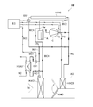
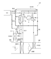
- FIG. 3 is a schematic explanatory diagram illustrating a flow of a refrigerant when a superheat degree of a gas-phase refrigerant discharged from a compressor is smaller than an upper limit value (a normal operation state) during a heating operation of the heat pump system according to the embodiment of the present invention.
- FIG. 4 is a schematic explanatory diagram illustrating a flow of a refrigerant when a superheat degree or a temperature of a gas-phase refrigerant discharged from a compressor is equal to or more than an upper limit value during a heating operation of the heat pump system according to the embodiment of the present invention.
- FIG. 1 is a schematic explanatory view showing the overall configuration of the heat pump system according to the embodiment of the present invention.
- the heat pump system HP includes a first indoor heat exchanger HXC1 and a second indoor heat exchanger HXC2 arranged in the air duct AD of the air conditioner of the vehicle.
- the first indoor heat exchanger HXC1 is arranged upstream of the second indoor heat exchanger HXC2 in the air flow direction indicated by the arrow FA.
- the air duct AD is divided into two passages, and the second indoor heat exchanger HXC2 is arranged in one of the passages.
- an air mix door AMD is rotatably attached to the upstream end of the partition member that divides the two passages, as indicated by arrows in the figure.
- air drawn into the air duct AD from outside or inside the vehicle by a blower fan (not shown) is cooled when passing through the first indoor heat exchanger HXC1, and is sent to the vehicle interior at low temperature. .
- the air sucked into the air duct AD is heated when passing through the second indoor heat exchanger HXC2, becomes high temperature, and is sent out to the vehicle interior.
- the air sucked into the air duct AD is cooled when passing through the first indoor heat exchanger HXC1, and the contained moisture is condensed and removed.
- the air is heated when passing through the two-room heat exchanger HXC2, and is sent out into the vehicle interior as dehumidified high-temperature air.
- the ratio of the air that passes through the second indoor heat exchanger HXC2 to the air that bypasses the second indoor heat exchanger HXC2 is an air mixing door. Adjusted by AMD.
- the heat pump system HP further includes a compressor C, a first expansion mechanism EX1 and a second expansion mechanism EX2, a first heat absorbing heat exchanger HXA1 and a second heat absorbing heat exchanger HXA2, and an accumulator A. These devices and the above-described first indoor heat exchanger HXC1 and second indoor heat exchanger HXC2 are arranged on the refrigerant circuit RC.
- the compressor C has a function of compressing a low-pressure gas-phase refrigerant and discharging it as a high-temperature and high-pressure superheated gas-phase refrigerant.
- a refrigerant temperature sensor TS and a refrigerant pressure sensor PS are arranged on the refrigerant circuit RC on the outlet side of the compressor C, and these sensors are electrically connected to the electronic control unit EC.
- the first expansion mechanism EX1 and the first heat absorbing heat exchanger HXA1, the second expansion mechanism EX2 and the second heat absorbing heat exchanger HXA2 are connected in series on the first branch flow path BC1 and the second branch flow path BC2, respectively. Are located.
- the first branch flow channel BC1 and the second branch flow channel BC2 are arranged in parallel on the refrigerant circuit RC between the branch point Pb and the junction Pm.
- the first heat-absorbing heat exchanger HXA1 is configured so that the refrigerant can absorb heat from cooling water for cooling a battery (not shown) mounted on the vehicle.
- a cooling water circuit WC through which the cooling water of the battery circulates is connected to the first heat absorbing heat exchanger HXA1.
- the cooling water which has cooled the battery and has become high temperature flows into the first heat absorbing heat exchanger HXA1 via the cooling water circuit WC, is cooled by being absorbed by the refrigerant, becomes low temperature, and becomes low temperature again. It returns to the battery via the cooling water circuit WC. Therefore, the first heat absorbing heat exchanger HXA1 has a function of cooling the battery, and thus can be referred to as a chiller.
- the second heat absorbing heat exchanger HXA2 is configured so that the refrigerant absorbs heat from outside air (air outside the vehicle).
- the first expansion mechanism EX1 and the second expansion mechanism EX2 are expansion valves whose opening degree can be continuously adjusted from zero (fully closed state) to a maximum opening degree (fully opened state), for example, an electronic expansion valve. It can be.
- the first expansion mechanism EX1 and the second expansion mechanism EX2 are electrically connected to the electronic control unit EC, respectively, and their opening degrees are determined by output signals from the refrigerant temperature sensor TS and the refrigerant pressure sensor PS as described later. Is controlled by the electronic control unit EC based on the
- the electronic control unit EC calculates the saturation temperature of the refrigerant at the pressure based on the refrigerant pressure measured by the refrigerant pressure sensor PS during the heating operation, and compares the saturation temperature with the refrigerant temperature measured by the refrigerant temperature sensor TS. And the degree of superheat SH of the gas-phase refrigerant discharged from the compressor C is calculated.
- the opening degree of the first expansion mechanism EX1 is always set to be larger than zero, whereas the opening degree of the second expansion mechanism EX2 is determined by the degree of opening of the gas-phase refrigerant discharged from the compressor C. Only when the superheat degree SH is equal to or higher than the upper limit value SHUL or when the temperature TD of the gas-phase refrigerant discharged from the compressor C is equal to or higher than the upper limit value TDUL, the value is set to be larger than zero.
- the second expansion mechanism EX2 When the degree of superheat SH, which has been equal to or higher than the upper limit SHUL, is lower than the upper limit SHUL, or when the temperature TD, which has been equal to or higher than the upper limit TDUL, is lower than the upper limit TDUL, the second expansion mechanism EX2 is activated. It is closed, and the refrigerant again flows only through the first branch channel BC1.
- FIG. 2 and 3 are schematic explanatory diagrams illustrating the flow of the refrigerant in the heat pump system HP during the heating operation.
- FIG. 2 illustrates a normal operation state (the degree of superheat of the gas-phase refrigerant discharged from the compressor is smaller than the upper limit value).
- FIG. 3 shows a case where the degree of superheat or the temperature of the gas-phase refrigerant discharged from the compressor is equal to or higher than the upper limit.
- the refrigerant that has reached the branch point Pb flows into the first branch flow channel BC1, as shown in FIG. 2, and expands in an isenthalpic manner when passing through the first expansion mechanism EX1, to be in a wet vapor state. .
- the refrigerant flowing out of the first expansion mechanism EX1 flows into the first heat absorbing heat exchanger HXA1 (chiller), absorbs heat from the cooling water of the battery flowing in the cooling water circuit WC, evaporates, and generates a low-pressure gaseous refrigerant. And flows into the accumulator A.
- the mixed liquid-phase refrigerant is removed, and only the gas-phase refrigerant returns to the compressor C.
- the electronic control unit EC outputs a larger opening signal to the first expansion mechanism EX1, thereby lowering the temperature of the refrigerant flowing out of the first expansion mechanism EX1, and suppressing an increase in the degree of superheat SH. try to. However, finally, the degree of superheat SH reaches its upper limit SHUL.
- the refrigerant that has reached the branch point Pb is, as shown in FIG. 3, the first branch channel BC1 and the second branch channel BC1 according to the respective opening degrees of the first expansion mechanism EX1 and the second expansion mechanism EX2. It flows into BC2 separately.
- the refrigerant flowing out of the first expansion mechanism EX1 flows into the first heat absorbing heat exchanger HXA1 (chiller), absorbs heat from the cooling water of the battery flowing in the cooling water circuit WC, evaporates, and generates a low-pressure gaseous refrigerant. And flows into the accumulator A.
- the refrigerant flowing out of the second expansion mechanism EX2 flows into the second heat absorbing heat exchanger HXA2, absorbs heat from the outside air, evaporates, and flows into the accumulator A as a low-pressure gas-phase refrigerant.
- the mixed liquid-phase refrigerant is removed, and only the gas-phase refrigerant returns to the compressor C.
- the temperature (degree of superheat SH) of the refrigerant discharged from the compressor C during the heating operation is excessive (exceeding the upper limit SHUL). It can be prevented from rising. As a result, there is no need to lower the rotation speed of the compressor C or stop the compressor C, and the operation of the air conditioner can be continued under desired conditions.
- the first heat absorbing heat exchanger HXA1 has been described as being configured to absorb the waste heat of the battery mounted on the vehicle through the cooling water of the battery.
- the heat absorbing heat exchanger HXA1 may be configured to absorb other waste heat generated in the vehicle.
- two heat absorbing heat exchangers a first heat absorbing heat exchanger HXA1 that absorbs heat from a battery mounted on a vehicle and a second heat absorbing heat exchanger HXA2 that absorbs heat from outside air
- three or more heat absorbing heat exchangers may be used, for example, by providing a further heat absorbing heat exchanger that absorbs other waste heat generated in the vehicle.
Landscapes
- Engineering & Computer Science (AREA)
- Physics & Mathematics (AREA)
- Mechanical Engineering (AREA)
- Thermal Sciences (AREA)
- General Engineering & Computer Science (AREA)
- Air-Conditioning For Vehicles (AREA)
Abstract
暖房運転時に、圧縮機から吐出される冷媒の温度(過熱度)が過剰に上昇することを防止し得る車両空調装置用ヒートポンプシステムを提供する。ヒートポンプシステム(HP)は、圧縮機(C)と、室内熱交換器(HXC2)とを冷媒回路(RC)上に備え、開度調整可能な第1膨張機構(EX1)と第1吸熱用熱交換器(HXA1)が直列に配置された第1分岐流路(BC1)と、開度調整可能な第2膨張機構(EX2)と第2吸熱用熱交換器(HXA2)が直列に配置された第2分岐流路(BC2)とが、室内熱交換器から圧縮機へ至る冷媒回路上に並列に配置されており、暖房運転中、第1膨張機構の開度は、常にゼロより大きく設定されており、第2膨張機構の開度は、圧縮機へ吸入される冷媒または圧縮機から吐出される冷媒の過熱度または温度が上限値以上となった場合にのみゼロより大きく設定される。
Description
本発明は、車両のエアコン(空調装置)に用いられるヒートポンプシステムに関し、特にその構成要素である圧縮機から吐出される冷媒の温度(過熱度)が過剰に上昇することを防止し得るヒートポンプシステムに関する。
車両のエアコンとして、ヒートポンプシステムを用いたものが知られている。
このようなヒートポンプシステムは、冷媒が循環する回路上に、圧縮機、車室内熱交換器、膨張機構及び車室外熱交換器を備えている。車室内熱交換器は、通常2個が、車外または車内の空気を吸入して温度を調整した後に車室内へ送り出す空気ダクト内に、空気の流れ方向において直列に配置されている。
冷房運転時には、圧縮機から吐出された高温高圧の冷媒が車室外熱交換器に流入して放熱(凝縮)した後、膨張機構を経て(通常は空気ダクト内の上流側に配置された)第1の車室内熱交換器に流入して吸熱(蒸発)し、その後、圧縮機へと還流する。空気ダクト内へ吸入された空気は、第1の車室内熱交換器において冷媒から吸熱されることにより冷却され、低温となって車室内へ送り出される。
暖房運転時には、圧縮機から吐出された高温高圧の冷媒が(通常は空気ダクト内の下流側に配置された)第2の車室内熱交換器に流入して放熱(凝縮)した後、膨張機構を経て車室外熱交換器に流入して吸熱(蒸発)し、その後、圧縮機へと還流する。空気ダクト内へ吸入された空気は、第2の車室内熱交換器において冷媒から吸熱することにより加熱され、高温となって車室内へ送り出される。
ところで、近年、車両のエアコンに用いられるヒートポンプシステムにおいて、エネルギー有効利用の観点から、車両の廃熱を吸熱源として利用することが提案されている。
このようなヒートポンプシステムは、例えば車両に搭載されたバッテリーの廃熱を、当該バッテリーを冷却するための冷却水を介して吸熱するように構成されている。具体的には、バッテリーを冷却するための冷却水の循環回路上にチラー(冷却器)が配置されており、ヒートポンプシステムの膨張機構から流出した冷媒が当該チラーに導入される。これにより、冷媒は、バッテリーを冷却して高温となった冷却水から吸熱することにより蒸発し、一方、冷却水は、冷媒から吸熱されることにより冷却され、低温となってバッテリーへと還流する。
このようなヒートポンプシステムにおいては、暖房運転時、車室外熱交換器において外気(車外の空気)から吸熱できない(または吸熱しないことが好ましい)条件では、チラーにおいてバッテリーの冷却水のみから吸熱していた。
しかしながら、バッテリーを冷却してチラーに流入する冷却水の温度が高くなると、圧縮機へ還流するヒートポンプシステムの冷媒の温度(過熱度)も高くなってしまう。その結果、圧縮機から吐出される冷媒の温度(過熱度)も高くなるので、当該温度が上限温度を超えないよう、圧縮機の回転数を低下させる、あるいは、圧縮機を停止させることが必要となり、所望の条件でエアコンの運転を続行することができなくなってしまう。
本発明は、このような問題点に鑑みてなされたものであって、暖房運転時に、圧縮機から吐出される冷媒の温度(過熱度)が過剰に上昇することを防止し得る車両空調装置用ヒートポンプシステムを提供することを目的とする。
上記課題を解決するために、本発明の車両空調装置用ヒートポンプシステムは、車両空調装置用のものであって、圧縮機と、室内熱交換器と、を冷媒回路上に備え、開度調整可能な第1膨張機構と第1吸熱用熱交換器が直列に配置された第1分岐流路と、開度調整可能な第2膨張機構と第2吸熱用熱交換器が直列に配置された第2分岐流路とが、前記室内熱交換器から前記圧縮機へ至る前記冷媒回路上に並列に配置されており、暖房運転中、前記第1膨張機構の開度は、常にゼロより大きく設定されており、前記第2膨張機構の開度は、前記圧縮機へ吸入される冷媒または前記圧縮機から吐出される冷媒の過熱度が上限値以上となった場合または前記圧縮機から吐出される冷媒の温度が上限値以上となった場合にのみゼロより大きく設定されることを特徴とする。
好ましくは、前記第1吸熱用熱交換器は、前記車両で発生する廃熱を吸熱するように構成されており、前記第2吸熱用熱交換器は、外気から吸熱するように構成されている。
好ましくは、前記第1吸熱用熱交換器は、前記車両に搭載されたバッテリーで発生する廃熱を、前記バッテリーの冷却水を介して吸熱するように構成されている。
好ましくは、前記冷媒の過熱度は、前記圧縮機の入口側または出口側の前記冷媒回路上に配置された冷媒温度センサ及び冷媒圧力センサを用いて算出される。
本発明のヒートポンプシステムによれば、暖房運転時に、圧縮機から吐出される冷媒の温度(過熱度)が過剰に上昇することを防止することができる。その結果、圧縮機の回転数を低下させたり、圧縮機を停止させたりする必要がなく、所望の条件でエアコンの運転を続行することができる。
以下、本発明の実施形態について、図面を参照して詳細に説明する。
図1は、本発明の実施形態のヒートポンプシステムの全体構成を示す概略説明図である。
図1に示すように、ヒートポンプシステムHPは、車両のエアコンの空気ダクトAD内に配置された第1室内熱交換器HXC1及び第2室内熱交換器HXC2を含んでいる。空気ダクトAD内において、第1室内熱交換器HXC1は、矢印FAで示す空気の流れ方向において、第2室内熱交換器HXC2より上流側に配置されている。また、第1室内熱交換器HXC1より下流において、空気ダクトADは2つの通路に区分されており、そのうちの一方の通路内に第2室内熱交換器HXC2が配置されている。さらに、2つの通路を区分する仕切り部材の上流端には、エアミックスドアAMDが、図中に矢印で示すように回動可能に取り付けられている。
冷房運転時には、送風ファン(図示省略)によって車外または車内から空気ダクトAD内に吸入された空気が、第1室内熱交換器HXC1を通過する際に冷却され、低温となって車室内へ送り出される。
一方、暖房運転時には、同様にして空気ダクトAD内に吸入された空気が、第2室内熱交換器HXC2を通過する際に加熱され、高温となって車室内へ送り出される。
なお、暖房運転時に空気の除湿を行う場合、空気ダクトAD内に吸入された空気は、第1室内熱交換器HXC1を通過する際に冷却されて含有水分が凝縮して除去され、その後、第2室内熱交換器HXC2を通過する際に加熱され、除湿された高温の空気として車室内へ送り出される。その際、第1室内熱交換器HXC1を通過した空気のうち、第2室内熱交換器HXC2を通過する空気と、当該第2室内熱交換器HXC2をバイパスする空気との比率が、エアミックスドアAMDによって調整される。
なお、暖房運転時に空気の除湿を行う場合、空気ダクトAD内に吸入された空気は、第1室内熱交換器HXC1を通過する際に冷却されて含有水分が凝縮して除去され、その後、第2室内熱交換器HXC2を通過する際に加熱され、除湿された高温の空気として車室内へ送り出される。その際、第1室内熱交換器HXC1を通過した空気のうち、第2室内熱交換器HXC2を通過する空気と、当該第2室内熱交換器HXC2をバイパスする空気との比率が、エアミックスドアAMDによって調整される。
ヒートポンプシステムHPは、さらに、圧縮機C、第1膨張機構EX1及び第2膨張機構EX2、第1吸熱用熱交換器HXA1及び第2吸熱用熱交換器HXA2、並びに、アキュムレータAを含んでおり、これらの機器、並びに、上述した第1室内熱交換器HXC1及び第2室内熱交換器HXC2は、冷媒回路RC上に配置されている。
圧縮機Cは、低圧の気相冷媒を圧縮し、高温高圧の過熱状態の気相冷媒として吐出する機能を有している。なお、圧縮機Cの出口側の冷媒回路RC上には、冷媒温度センサTS及び冷媒圧力センサPSが配置されており、これらのセンサは、電子制御装置ECと電気的に接続されている。
第1膨張機構EX1及び第1吸熱用熱交換器HXA1、第2膨張機構EX2及び第2吸熱用熱交換器HXA2は、それぞれ第1分岐流路BC1、第2分岐流路BC2の上に直列に配置されている。そして、第1分岐流路BC1と第2分岐流路BC2は、冷媒回路RC上において分岐点Pbと合流点Pmの間で互いに並列に配置されている。
2つの吸熱用熱交換器のうち、第1吸熱用熱交換器HXA1は、冷媒が、車両に搭載されたバッテリー(図示省略)を冷却するための冷却水から吸熱し得るように構成されている。そのために、第1吸熱用熱交換器HXA1には、バッテリーの冷却水が循環する冷却水回路WCが接続されている。これにより、バッテリーを冷却して高温となった冷却水は、冷却水回路WCを経て第1吸熱用熱交換器HXA1に流入し、冷媒から吸熱されることにより冷却され、低温となって、再び冷却水回路WCを経てバッテリーへと還流する。したがって、第1吸熱用熱交換器HXA1は、バッテリーを冷却する機能を有していることから、チラーと称することもできる。
一方、第2吸熱用熱交換器HXA2は、冷媒が、外気(車外の空気)から吸熱するように構成されている。
また、第1膨張機構EX1及び第2膨張機構EX2は、その開度がゼロ(全閉状態)から最大開度(全開状態)まで連続的に調整可能な膨張弁であって、例えば電子膨張弁とすることができる。第1膨張機構EX1及び第2膨張機構EX2は、それぞれ電子制御装置ECと電気的に接続されており、その開度は、後述するように、冷媒温度センサTS及び冷媒圧力センサPSからの出力信号に基づいて、電子制御装置ECによって制御される。
電子制御装置ECは、暖房運転中、冷媒圧力センサPSによって計測された冷媒の圧力に基づいて当該圧力における冷媒の飽和温度を算出し、冷媒温度センサTSによって計測された冷媒の温度との比較を通じて、圧縮機Cから吐出される気相冷媒の過熱度SHを算出する。
そして、算出された過熱度SHが上限値SHULより小さい場合には、第1膨張機構EX1に対してはゼロより大きい所定の開度信号を、第2膨張機構EX2に対してはゼロ開度(全閉状態)信号を出力する。
一方、算出された過熱度SHが上限値SHUL以上である場合、または、冷媒温度センサTSによって計測された冷媒の温度(すなわち、圧縮機Cから吐出される冷媒の温度TD)が上限値TDUL以上である場合には、第1膨張機構EX1に対してはゼロより大きい所定の開度信号を出力しつつ、第2膨張機構EX2に対してもゼロより大きい所定の開度信号を出力する。
換言すれば、暖房運転中、第1膨張機構EX1の開度は常にゼロより大きく設定されているのに対し、第2膨張機構EX2の開度は、圧縮機Cから吐出される気相冷媒の過熱度SHが上限値SHUL以上となった場合、または、圧縮機Cから吐出される気相冷媒の温度TDが上限値TDUL以上となった場合にのみゼロより大きく設定されることになる。
これにより、圧縮機Cから吐出される気相冷媒の過熱度SHが上限値SHULより小さい場合には、第1膨張機構EX1のみが開き、冷媒は第1分岐流路BC1のみを流れる。一方、圧縮機Cから吐出される気相冷媒の過熱度SHが上限値SHUL以上である場合、または、圧縮機Cから吐出される気相冷媒の温度TDが上限値TDUL以上である場合には、第1膨張機構EX1及び第2膨張機構EX2の両方が開き、冷媒は第1分岐流路BC1及び第2分岐流路BC2の両方を流れることになる。なお、上限値SHUL以上となっていた過熱度SHが上限値SHULを下回った場合、または、上限値TDUL以上となっていた温度TDが上限値TDULを下回った場合は、第2膨張機構EX2が閉じられ、冷媒は再び第1分岐流路BC1のみを流れるようになる。
以上のように構成されたヒートポンプシステムHPの暖房運転時における作動について、以下で説明する。
図2及び図3は、暖房運転時におけるヒートポンプシステムHPの冷媒の流れを示す概略説明図であり、図2は通常運転状態(圧縮機から吐出される気相冷媒の過熱度が上限値より小さい場合)を、図3は圧縮機から吐出される気相冷媒の過熱度または温度が上限値以上である場合を、それぞれ示している。
圧縮機Cから吐出された高温高圧の過熱状態の気相冷媒は、第2室内熱交換器HXC2に流入し、空気ダクトAD内を流れる空気に放熱して凝縮し、高圧の液相冷媒となる、このとき、空気ダクトAD内を流れる空気は、冷媒からの吸熱によって加熱され、高温となって車室内へ送り出される。
第2室内熱交換器HXC2から流出した冷媒は、冷媒回路RCを流れて分岐点Pbに達する。
ここで、ヒートポンプシステムHPの通常運転状態、すなわち圧縮機Cから吐出される気相冷媒の過熱度SHが上限値SHULより小さい場合には、上述したように、第1分岐流路BC1上の第1膨張機構EX1のみが開いており、第2分岐流路BC2上の第2膨張機構EX2は閉じている。
したがって、分岐点Pbに達した冷媒は、図2に示すように、第1分岐流路BC1に流入し、第1膨張機構EX1を通過する際に等エンタルピ的に膨張して湿り蒸気状態となる。
第1膨張機構EX1を流出した冷媒は、第1吸熱用熱交換器HXA1(チラー)に流入し、冷却水回路WC内を流れるバッテリーの冷却水から吸熱して蒸発し、低圧の気相冷媒となってアキュムレータAに流入する。
アキュムレータAでは、混入した液相冷媒が除去され、気相冷媒のみが圧縮機Cに還流する。
一方、ヒートポンプシステムHPの通常運転状態において、バッテリーの温度は徐々に上昇し、第1吸熱用熱交換器HXA1(チラー)に流入する冷却水の温度も徐々に上昇する。その結果、圧縮機Cから吐出される気相冷媒の過熱度SHも徐々に大きくなる。
このとき、電子制御装置ECは、第1膨張機構EX1に対してより大きな開度信号を出力することにより、第1膨張機構EX1から流出する冷媒の温度を低下させ、過熱度SHの上昇を抑制しようとする。しかし、遂には、過熱度SHがその上限値SHULに到達することになる。
このように、圧縮機Cから吐出される気相冷媒の過熱度SHが上限値SHUL以上、または、圧縮機Cから吐出される気相冷媒の温度TDが上限値TDUL以上になると、上述したように、それまでは閉じられていた第2膨張機構EX2が開かれ、第1膨張機構EX1及び第2膨張機構EX2の両方が開いた状態となる。
したがって、分岐点Pbに達した冷媒は、図3に示すように、第1膨張機構EX1及び第2膨張機構EX2のそれぞれの開度に応じて、第1分岐流路BC1と第2分岐流路BC2に分かれて流入する。
それぞれの分岐流路に流入した冷媒は、第1膨張機構EX1及び第2膨張機構EX2を通過する際にそれぞれ等エンタルピ的に膨張して湿り蒸気状態となる。
第1膨張機構EX1を流出した冷媒は、第1吸熱用熱交換器HXA1(チラー)に流入し、冷却水回路WC内を流れるバッテリーの冷却水から吸熱して蒸発し、低圧の気相冷媒となってアキュムレータAに流入する。
同様に、第2膨張機構EX2を流出した冷媒は、第2吸熱用熱交換器HXA2に流入し、外気から吸熱して蒸発し、低圧の気相冷媒となってアキュムレータAに流入する。
アキュムレータAでは、混入した液相冷媒が除去され、気相冷媒のみが圧縮機Cに還流する。
上述したように、圧縮機Cから吐出される気相冷媒の過熱度SHが上限値SHULに到達、または、圧縮機Cから吐出される気相冷媒の温度TDが上限値TDULに到達した時、第2吸熱用熱交換器HXA2は未だ低温の状態にあるので、分岐点Pbから第2分岐流路BC2に流入して第2吸熱用熱交換器HXA2を通過して合流点Pmに至る冷媒の温度は、分岐点Pbから第1分岐流路BC1に流入して既に高温の状態となっている第1吸熱用熱交換器HXA1を通過して合流点Pmに至る冷媒の温度と比較して低い。
このように、第1分岐流路BC1(第1吸熱用熱交換器HXA1)から流出する冷媒に、これより低温の第2分岐流路BC2(第2吸熱用熱交換器HXA2)から流出する冷媒を混合させることにより、合流点Pmより下流における冷媒の温度を低下させることができ、圧縮機Cから吐出される気相冷媒の過熱度SHまたは温度TDの上昇を抑え、ひいてはこれを低下させることができる。
以上で説明したように、本発明の実施形態のヒートポンプシステムHPによれば、暖房運転時に、圧縮機Cから吐出される冷媒の温度(過熱度SH)が(上限値SHULを超えて)過剰に上昇することを防止することができる。その結果、圧縮機Cの回転数を低下させたり、圧縮機Cを停止させたりする必要がなく、所望の条件でエアコンの運転を続行することができる。
なお、以上においては、冷媒温度センサTS及び冷媒圧力センサPSを圧縮機Cの出口側の冷媒回路RC上に配置した例について説明したが、これらのセンサは、圧縮機Cの入口側の冷媒回路RC上に配置してもよい。
また、以上においては、第1吸熱用熱交換器HXA1を、車両に搭載されたバッテリーの廃熱を、当該バッテリーの冷却水を介して吸熱するように構成されたものとして説明したが、第1吸熱用熱交換器HXA1は、車両で発生するその他の廃熱を吸熱するように構成されてもよい。
さらに、以上においては、2つの吸熱用熱交換器(車両に搭載されたバッテリーから吸熱する第1吸熱用熱交換器HXA1及び外気から吸熱する第2吸熱用熱交換器HXA2)を用いる例について説明したが、例えば車両において発生する他の廃熱を吸熱する更なる吸熱用熱交換器を設けることにより、3つ以上の吸熱用熱交換器を用いてもよい。
さらに、以上においては、2つの吸熱用熱交換器(車両に搭載されたバッテリーから吸熱する第1吸熱用熱交換器HXA1及び外気から吸熱する第2吸熱用熱交換器HXA2)を用いる例について説明したが、例えば車両において発生する他の廃熱を吸熱する更なる吸熱用熱交換器を設けることにより、3つ以上の吸熱用熱交換器を用いてもよい。
BC1 第1分岐流路
BC2 第2分岐流路
C 圧縮機
EX1 第1膨張機構
EX2 第2膨張機構
HXA1 第1吸熱用熱交換器
HXA2 第2吸熱用熱交換器
HXC2 第2室内熱交換器(室内熱交換器)
HP ヒートポンプシステム
RC 冷媒回路
BC2 第2分岐流路
C 圧縮機
EX1 第1膨張機構
EX2 第2膨張機構
HXA1 第1吸熱用熱交換器
HXA2 第2吸熱用熱交換器
HXC2 第2室内熱交換器(室内熱交換器)
HP ヒートポンプシステム
RC 冷媒回路
Claims (4)
- 圧縮機と、室内熱交換器と、を冷媒回路上に備え、
開度調整可能な第1膨張機構と第1吸熱用熱交換器が直列に配置された第1分岐流路と、
開度調整可能な第2膨張機構と第2吸熱用熱交換器が直列に配置された第2分岐流路とが、
前記室内熱交換器から前記圧縮機へ至る前記冷媒回路上に並列に配置されている車両空調装置用ヒートポンプシステムにおいて、
暖房運転中、
前記第1膨張機構の開度は、常にゼロより大きく設定されており、
前記第2膨張機構の開度は、前記圧縮機へ吸入される冷媒または前記圧縮機から吐出される冷媒の過熱度が上限値以上となった場合または前記圧縮機から吐出される冷媒の温度が上限値以上となった場合にのみゼロより大きく設定される
ことを特徴とする車両空調装置用ヒートポンプシステム。 - 前記第1吸熱用熱交換器は、前記車両で発生する廃熱を吸熱するように構成されており、
前記第2吸熱用熱交換器は、外気から吸熱するように構成されている
ことを特徴とする請求項1に記載の車両空調装置用ヒートポンプシステム。 - 前記第1吸熱用熱交換器は、前記車両に搭載されたバッテリーで発生する廃熱を、前記バッテリーの冷却水を介して吸熱するように構成されている
ことを特徴とする請求項2に記載の車両空調装置用ヒートポンプシステム。 - 前記冷媒の過熱度は、前記圧縮機の入口側または出口側の前記冷媒回路上に配置された冷媒温度センサ及び冷媒圧力センサを用いて算出される
ことを特徴とする請求項1~3のいずれか1項に記載の車両空調装置用ヒートポンプシステム。
Priority Applications (3)
| Application Number | Priority Date | Filing Date | Title |
|---|---|---|---|
| US17/269,708 US11794555B2 (en) | 2018-08-30 | 2019-08-23 | Heat pump system for vehicle air conditioning devices |
| DE112019004368.4T DE112019004368T5 (de) | 2018-08-30 | 2019-08-23 | Wärmepumpensystem für eine Fahrzeugklimatisierungsvorrichtung |
| CN201980054379.5A CN112585413B (zh) | 2018-08-30 | 2019-08-23 | 车辆空调装置用热泵系统 |
Applications Claiming Priority (2)
| Application Number | Priority Date | Filing Date | Title |
|---|---|---|---|
| JP2018-161397 | 2018-08-30 | ||
| JP2018161397A JP7117945B2 (ja) | 2018-08-30 | 2018-08-30 | 車両空調装置用ヒートポンプシステム |
Publications (1)
| Publication Number | Publication Date |
|---|---|
| WO2020045261A1 true WO2020045261A1 (ja) | 2020-03-05 |
Family
ID=69644255
Family Applications (1)
| Application Number | Title | Priority Date | Filing Date |
|---|---|---|---|
| PCT/JP2019/032953 Ceased WO2020045261A1 (ja) | 2018-08-30 | 2019-08-23 | 車両空調装置用ヒートポンプシステム |
Country Status (5)
| Country | Link |
|---|---|
| US (1) | US11794555B2 (ja) |
| JP (1) | JP7117945B2 (ja) |
| CN (1) | CN112585413B (ja) |
| DE (1) | DE112019004368T5 (ja) |
| WO (1) | WO2020045261A1 (ja) |
Cited By (1)
| Publication number | Priority date | Publication date | Assignee | Title |
|---|---|---|---|---|
| WO2022194806A1 (fr) * | 2021-03-15 | 2022-09-22 | Valeo Systemes Thermiques | Système de conditionnement thermique |
Families Citing this family (6)
| Publication number | Priority date | Publication date | Assignee | Title |
|---|---|---|---|---|
| JP7117945B2 (ja) * | 2018-08-30 | 2022-08-15 | サンデン株式会社 | 車両空調装置用ヒートポンプシステム |
| FR3100491A1 (fr) * | 2019-09-09 | 2021-03-12 | Valeo Systemes Thermiques | Circuit de fluide refrigerant pour vehicule et procede de contrôle d’un tel circuit |
| KR102896177B1 (ko) * | 2019-11-15 | 2025-12-04 | 현대자동차 주식회사 | 차량용 히트펌프 시스템 |
| KR102854357B1 (ko) | 2020-08-27 | 2025-09-02 | 한온시스템 주식회사 | 차량의 열관리 시스템 |
| JP7494139B2 (ja) * | 2021-03-24 | 2024-06-03 | サンデン株式会社 | 車両用空調装置 |
| CN117382383A (zh) * | 2023-11-30 | 2024-01-12 | 浙江吉利控股集团有限公司 | 热泵系统及其制冷剂回流控制方法、装置和车辆 |
Citations (4)
| Publication number | Priority date | Publication date | Assignee | Title |
|---|---|---|---|---|
| JP2011140291A (ja) * | 2010-01-11 | 2011-07-21 | Denso Corp | 車両用空調装置 |
| WO2012137468A1 (ja) * | 2011-04-08 | 2012-10-11 | 株式会社テージーケー | 車両用冷暖房装置 |
| WO2014073151A1 (ja) * | 2012-11-07 | 2014-05-15 | 株式会社デンソー | 冷凍サイクル装置 |
| WO2014073150A1 (ja) * | 2012-11-07 | 2014-05-15 | 株式会社デンソー | 冷却装置 |
Family Cites Families (34)
| Publication number | Priority date | Publication date | Assignee | Title |
|---|---|---|---|---|
| US2047827A (en) * | 1934-03-23 | 1936-07-14 | Westinghouse Electric & Mfg Co | Control mechanism |
| US3150498A (en) * | 1962-03-08 | 1964-09-29 | Ray Winther Company | Method and apparatus for defrosting refrigeration systems |
| US3390540A (en) * | 1966-08-16 | 1968-07-02 | Carrier Corp | Multiple evaporator refrigeration systems |
| US4760707A (en) * | 1985-09-26 | 1988-08-02 | Carrier Corporation | Thermo-charger for multiplex air conditioning system |
| JPH0799286B2 (ja) * | 1989-12-14 | 1995-10-25 | ダイキン工業株式会社 | 空気調和機の湿り制御装置 |
| US5077982A (en) * | 1990-02-14 | 1992-01-07 | York International Corporation | Multizone air conditioning system and evaporators therefor |
| AU636215B2 (en) * | 1990-04-23 | 1993-04-22 | Mitsubishi Denki Kabushiki Kaisha | Air conditioning apparatus |
| US5878810A (en) * | 1990-11-28 | 1999-03-09 | Kabushiki Kaisha Toshiba | Air-conditioning apparatus |
| US5237833A (en) * | 1991-01-10 | 1993-08-24 | Mitsubishi Denki Kabushiki Kaisha | Air-conditioning system |
| EP0800940A3 (en) * | 1996-04-10 | 2001-06-06 | Denso Corporation | Vehicular air conditioning system for electric vehicles |
| US6321549B1 (en) * | 2000-04-14 | 2001-11-27 | Carrier Corporation | Electronic expansion valve control system |
| JP2004218964A (ja) * | 2003-01-16 | 2004-08-05 | Matsushita Electric Ind Co Ltd | 冷凍装置 |
| JP3757967B2 (ja) * | 2003-08-25 | 2006-03-22 | ダイキン工業株式会社 | 冷凍装置 |
| KR100761285B1 (ko) * | 2004-12-10 | 2007-09-27 | 엘지전자 주식회사 | 공기조화기 |
| US8096141B2 (en) * | 2005-01-25 | 2012-01-17 | Trane International Inc. | Superheat control by pressure ratio |
| KR101119335B1 (ko) * | 2005-02-15 | 2012-03-06 | 엘지전자 주식회사 | 냉난방 동시형 멀티 에어컨 및 그의 응축냉매 제어방법 |
| KR100677266B1 (ko) * | 2005-02-17 | 2007-02-02 | 엘지전자 주식회사 | 냉난방 동시형 멀티 에어컨 |
| JP5324749B2 (ja) * | 2006-09-11 | 2013-10-23 | ダイキン工業株式会社 | 冷凍装置 |
| KR100826180B1 (ko) * | 2006-12-26 | 2008-04-30 | 엘지전자 주식회사 | 냉장고 및 그 제어방법 |
| WO2009039850A1 (en) * | 2007-09-25 | 2009-04-02 | Danfoss A/S | A method and a control system for controlling an opening degree of a valve |
| WO2009048466A1 (en) * | 2007-10-10 | 2009-04-16 | Carrier Corporation | Suction superheat control based on refrigerant condition at discharge |
| US8156750B2 (en) * | 2008-07-29 | 2012-04-17 | Agri Control Technologies, Inc. | Dynamic superheat control for high efficiency refrigeration system |
| US8539785B2 (en) * | 2009-02-18 | 2013-09-24 | Emerson Climate Technologies, Inc. | Condensing unit having fluid injection |
| CN102483273B (zh) * | 2009-09-09 | 2014-09-17 | 三菱电机株式会社 | 空气调节装置 |
| JP5475874B2 (ja) * | 2010-04-30 | 2014-04-16 | ダイキン工業株式会社 | ヒートポンプシステム |
| CN102555726B (zh) * | 2010-12-29 | 2014-10-15 | 财团法人车辆研究测试中心 | 应用于电动车热管理的多功能空调系统 |
| US9410727B1 (en) * | 2012-07-27 | 2016-08-09 | Hill Phoenix, Inc. | Systems and methods for defrosting an evaporator in a refrigeration system |
| JP6125325B2 (ja) * | 2013-05-20 | 2017-05-10 | サンデンホールディングス株式会社 | 車両用空気調和装置 |
| CN104422024B (zh) * | 2013-09-05 | 2019-03-12 | 杭州三花研究院有限公司 | 汽车空调系统及其控制方法 |
| US20150059373A1 (en) * | 2013-09-05 | 2015-03-05 | Beckett Performance Products, Llc | Superheat and sub-cooling control of refrigeration system |
| JP6017058B2 (ja) * | 2013-10-24 | 2016-10-26 | 三菱電機株式会社 | 空気調和装置 |
| US9696078B2 (en) * | 2013-11-20 | 2017-07-04 | Mitsubishi Electric Corporation | Refrigeration cycle apparatus |
| CN106403348B (zh) * | 2016-11-28 | 2022-07-01 | 广州华凌制冷设备有限公司 | 一种空调器及其制冷控制方法 |
| JP7117945B2 (ja) * | 2018-08-30 | 2022-08-15 | サンデン株式会社 | 車両空調装置用ヒートポンプシステム |
-
2018
- 2018-08-30 JP JP2018161397A patent/JP7117945B2/ja active Active
-
2019
- 2019-08-23 DE DE112019004368.4T patent/DE112019004368T5/de active Pending
- 2019-08-23 CN CN201980054379.5A patent/CN112585413B/zh active Active
- 2019-08-23 WO PCT/JP2019/032953 patent/WO2020045261A1/ja not_active Ceased
- 2019-08-23 US US17/269,708 patent/US11794555B2/en active Active
Patent Citations (4)
| Publication number | Priority date | Publication date | Assignee | Title |
|---|---|---|---|---|
| JP2011140291A (ja) * | 2010-01-11 | 2011-07-21 | Denso Corp | 車両用空調装置 |
| WO2012137468A1 (ja) * | 2011-04-08 | 2012-10-11 | 株式会社テージーケー | 車両用冷暖房装置 |
| WO2014073151A1 (ja) * | 2012-11-07 | 2014-05-15 | 株式会社デンソー | 冷凍サイクル装置 |
| WO2014073150A1 (ja) * | 2012-11-07 | 2014-05-15 | 株式会社デンソー | 冷却装置 |
Cited By (2)
| Publication number | Priority date | Publication date | Assignee | Title |
|---|---|---|---|---|
| WO2022194806A1 (fr) * | 2021-03-15 | 2022-09-22 | Valeo Systemes Thermiques | Système de conditionnement thermique |
| US12558939B2 (en) | 2021-03-15 | 2026-02-24 | Valeo Systemes Thermiques | Thermal conditioning system |
Also Published As
| Publication number | Publication date |
|---|---|
| JP7117945B2 (ja) | 2022-08-15 |
| DE112019004368T5 (de) | 2021-05-20 |
| JP2020034228A (ja) | 2020-03-05 |
| US11794555B2 (en) | 2023-10-24 |
| CN112585413A (zh) | 2021-03-30 |
| CN112585413B (zh) | 2022-07-01 |
| US20210197648A1 (en) | 2021-07-01 |
Similar Documents
| Publication | Publication Date | Title |
|---|---|---|
| JP7117945B2 (ja) | 車両空調装置用ヒートポンプシステム | |
| JP6073651B2 (ja) | 車両用空気調和装置 | |
| US7360372B2 (en) | Refrigeration system | |
| US8948966B2 (en) | Heat pump system for vehicle and method of controlling the same | |
| CN106537065B (zh) | 制冷循环装置 | |
| US9810465B2 (en) | Heat pump system for vehicle | |
| CN103373197B (zh) | 具有热泵功能和再热功能的空调设备的制冷剂回路 | |
| US9902235B2 (en) | Vehicle air-conditioning apparatus | |
| US10647178B2 (en) | Air conditioner for vehicle | |
| US20110113800A1 (en) | Vehicle Air-Conditioning Apparatus | |
| JP2019045034A (ja) | 冷凍サイクル装置 | |
| KR102111323B1 (ko) | 차량용 히트 펌프 시스템 | |
| WO2019065039A1 (ja) | 冷凍サイクル装置 | |
| JP5796007B2 (ja) | 車両用空調装置の運転制御方法 | |
| WO2022064946A1 (ja) | 車両用空調装置 | |
| CN112440665A (zh) | 车辆用空调装置 | |
| CN109416206B (zh) | 设计用于能量源的热控制的制冷剂回路 | |
| JPH06183247A (ja) | 空気調和装置 | |
| WO2019172135A1 (ja) | 空調装置 | |
| WO2023002993A1 (ja) | 車両用空調装置 | |
| JP7321906B2 (ja) | 車両用空調装置及び運転モード切替方法 | |
| JP4167719B2 (ja) | 冷凍回路及びこれを使用した空調装置 | |
| JP7494139B2 (ja) | 車両用空調装置 | |
| WO2025243950A1 (ja) | 冷凍サイクル装置 | |
| JP2021146958A (ja) | 車両用空調装置及び運転モード切替制御方法 |
Legal Events
| Date | Code | Title | Description |
|---|---|---|---|
| 121 | Ep: the epo has been informed by wipo that ep was designated in this application |
Ref document number: 19855213 Country of ref document: EP Kind code of ref document: A1 |
|
| 122 | Ep: pct application non-entry in european phase |
Ref document number: 19855213 Country of ref document: EP Kind code of ref document: A1 |