WO2020045089A1 - 複合部材およびその製造方法 - Google Patents
複合部材およびその製造方法 Download PDFInfo
- Publication number
- WO2020045089A1 WO2020045089A1 PCT/JP2019/031896 JP2019031896W WO2020045089A1 WO 2020045089 A1 WO2020045089 A1 WO 2020045089A1 JP 2019031896 W JP2019031896 W JP 2019031896W WO 2020045089 A1 WO2020045089 A1 WO 2020045089A1
- Authority
- WO
- WIPO (PCT)
- Prior art keywords
- composite member
- coating layer
- intermediate layer
- less
- base material
- Prior art date
- Legal status (The legal status is an assumption and is not a legal conclusion. Google has not performed a legal analysis and makes no representation as to the accuracy of the status listed.)
- Ceased
Links
Images

Classifications
-
- C—CHEMISTRY; METALLURGY
- C23—COATING METALLIC MATERIAL; COATING MATERIAL WITH METALLIC MATERIAL; CHEMICAL SURFACE TREATMENT; DIFFUSION TREATMENT OF METALLIC MATERIAL; COATING BY VACUUM EVAPORATION, BY SPUTTERING, BY ION IMPLANTATION OR BY CHEMICAL VAPOUR DEPOSITION, IN GENERAL; INHIBITING CORROSION OF METALLIC MATERIAL OR INCRUSTATION IN GENERAL
- C23C—COATING METALLIC MATERIAL; COATING MATERIAL WITH METALLIC MATERIAL; SURFACE TREATMENT OF METALLIC MATERIAL BY DIFFUSION INTO THE SURFACE, BY CHEMICAL CONVERSION OR SUBSTITUTION; COATING BY VACUUM EVAPORATION, BY SPUTTERING, BY ION IMPLANTATION OR BY CHEMICAL VAPOUR DEPOSITION, IN GENERAL
- C23C18/00—Chemical coating by decomposition of either liquid compounds or solutions of the coating forming compounds, without leaving reaction products of surface material in the coating; Contact plating
- C23C18/16—Chemical coating by decomposition of either liquid compounds or solutions of the coating forming compounds, without leaving reaction products of surface material in the coating; Contact plating by reduction or substitution, e.g. electroless plating
- C23C18/18—Pretreatment of the material to be coated
-
- C—CHEMISTRY; METALLURGY
- C23—COATING METALLIC MATERIAL; COATING MATERIAL WITH METALLIC MATERIAL; CHEMICAL SURFACE TREATMENT; DIFFUSION TREATMENT OF METALLIC MATERIAL; COATING BY VACUUM EVAPORATION, BY SPUTTERING, BY ION IMPLANTATION OR BY CHEMICAL VAPOUR DEPOSITION, IN GENERAL; INHIBITING CORROSION OF METALLIC MATERIAL OR INCRUSTATION IN GENERAL
- C23C—COATING METALLIC MATERIAL; COATING MATERIAL WITH METALLIC MATERIAL; SURFACE TREATMENT OF METALLIC MATERIAL BY DIFFUSION INTO THE SURFACE, BY CHEMICAL CONVERSION OR SUBSTITUTION; COATING BY VACUUM EVAPORATION, BY SPUTTERING, BY ION IMPLANTATION OR BY CHEMICAL VAPOUR DEPOSITION, IN GENERAL
- C23C18/00—Chemical coating by decomposition of either liquid compounds or solutions of the coating forming compounds, without leaving reaction products of surface material in the coating; Contact plating
- C23C18/16—Chemical coating by decomposition of either liquid compounds or solutions of the coating forming compounds, without leaving reaction products of surface material in the coating; Contact plating by reduction or substitution, e.g. electroless plating
- C23C18/31—Coating with metals
- C23C18/32—Coating with nickel, cobalt or mixtures thereof with phosphorus or boron
- C23C18/34—Coating with nickel, cobalt or mixtures thereof with phosphorus or boron using reducing agents
-
- C—CHEMISTRY; METALLURGY
- C23—COATING METALLIC MATERIAL; COATING MATERIAL WITH METALLIC MATERIAL; CHEMICAL SURFACE TREATMENT; DIFFUSION TREATMENT OF METALLIC MATERIAL; COATING BY VACUUM EVAPORATION, BY SPUTTERING, BY ION IMPLANTATION OR BY CHEMICAL VAPOUR DEPOSITION, IN GENERAL; INHIBITING CORROSION OF METALLIC MATERIAL OR INCRUSTATION IN GENERAL
- C23C—COATING METALLIC MATERIAL; COATING MATERIAL WITH METALLIC MATERIAL; SURFACE TREATMENT OF METALLIC MATERIAL BY DIFFUSION INTO THE SURFACE, BY CHEMICAL CONVERSION OR SUBSTITUTION; COATING BY VACUUM EVAPORATION, BY SPUTTERING, BY ION IMPLANTATION OR BY CHEMICAL VAPOUR DEPOSITION, IN GENERAL
- C23C28/00—Coating for obtaining at least two superposed coatings either by methods not provided for in a single one of groups C23C2/00 - C23C26/00 or by combinations of methods provided for in subclasses C23C and C25C or C25D
-
- C—CHEMISTRY; METALLURGY
- C25—ELECTROLYTIC OR ELECTROPHORETIC PROCESSES; APPARATUS THEREFOR
- C25D—PROCESSES FOR THE ELECTROLYTIC OR ELECTROPHORETIC PRODUCTION OF COATINGS; ELECTROFORMING; APPARATUS THEREFOR
- C25D5/00—Electroplating characterised by the process; Pretreatment or after-treatment of workpieces
- C25D5/34—Pretreatment of metallic surfaces to be electroplated
- C25D5/42—Pretreatment of metallic surfaces to be electroplated of light metals
- C25D5/44—Aluminium
-
- C—CHEMISTRY; METALLURGY
- C25—ELECTROLYTIC OR ELECTROPHORETIC PROCESSES; APPARATUS THEREFOR
- C25D—PROCESSES FOR THE ELECTROLYTIC OR ELECTROPHORETIC PRODUCTION OF COATINGS; ELECTROFORMING; APPARATUS THEREFOR
- C25D7/00—Electroplating characterised by the article coated
- C25D7/06—Wires; Strips; Foils
Definitions
- the present disclosure relates to a composite member and a method for manufacturing the same.
- This application claims the priority based on Japanese Patent Application No. 2018-160691 filed on Aug. 29, 2018, and incorporates all the contents described in these Japanese applications.
- Patent Literature 1 discloses that double zincate treatment is performed using two specific and different plating baths.
- Patent Document 2 discloses a method of forming an anodic oxide film on the surface of aluminum and then dissolving and removing a part of the film.
- Patent Document 3 discloses a method of forming an anodic oxide film having a concavo-convex structure on the surface of aluminum and electrolytically depositing particulate nickel.
- JP 2008-190034 A JP-A-61-84395 JP-A-11-302854
- One aspect of the present disclosure is: A substrate made of pure aluminum or an aluminum alloy, An intermediate layer provided on the surface of the base material, A coating layer provided on the surface of the intermediate layer, The intermediate layer includes aluminum oxide, and has a plurality of protrusions protruding from the base material side, The height H of the protrusion is not less than 10 nm and not more than 100 nm,
- the cover layer relates to a composite member including nickel.
- Another aspect of the present disclosure includes: A substrate made of pure aluminum or an aluminum alloy, An intermediate layer provided on the surface of the base material, A coating layer provided on the surface of the intermediate layer, The intermediate layer includes an aluminum oxide,
- the coating layer is a composite member containing nickel and having a thickness of 2.2 mm or less, After heating the composite member at 500 ° C. for 10 minutes, when the composite member cooled to room temperature is bent, a curvature radius R at which peeling of the coating layer occurs is equal to or less than the thickness D1 of the base material. About.
- Yet another aspect of the present disclosure includes: A step of preparing a substrate composed of pure aluminum or an aluminum alloy, Forming an intermediate layer containing aluminum oxide on the surface of the base material, Forming a coating layer containing nickel on the surface of the intermediate layer, The step of forming the intermediate layer, Forming a thin film of aluminum oxide having a thickness of 2 nm or more and 10 nm or less on the surface of the base material; A step of subjecting the substrate on which the thin film of the aluminum oxide is formed to electroless nickel plating using a plating bath having a pH of 8 or more and less than 10 at 25 ° C. About the method.
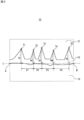
- FIG. 1 is a cross-sectional view schematically illustrating a composite member according to an embodiment of the present disclosure.
- FIG. 2 is an enlarged sectional view schematically showing a part of the composite member shown in FIG.
- a composite member includes a base made of pure aluminum or an aluminum alloy, an intermediate layer provided on a surface of the base, and a surface provided on the surface of the intermediate layer.
- the aluminum oxide is arranged in a fine projection shape. Therefore, the composite member has high adhesion between the base material and the coating layer. Further, since the intermediate layer is formed thin, thermal stress generated between the base material and the intermediate layer is small. Therefore, even if the composite member is bent after heating, peeling of the coating layer is suppressed.
- the pitch between the adjacent protrusions may be 1 nm or more and 100 nm or less. Since the fine projections are arranged at a fine pitch, the adhesion between the base material and the coating layer is further improved.
- the thickness D1 of the base material may be 0.01 mm or more and 2 mm or less.
- the thickness D1 is 0.01 mm or more, high bending resistance is obtained. Since the intermediate layer of the present embodiment is thin, deterioration of the substrate surface when the intermediate layer is formed is suppressed. Therefore, if the base material has a thickness of 0.01 mm or more, the strength of the base material can be sufficiently maintained. Further, even with a relatively thick substrate of 2 mm or less, peeling due to bending is easily suppressed.
- the thickness D2 of the coating layer may be 0.1 ⁇ m or more and 20 ⁇ m or less.
- the thickness D2 is 0.1 ⁇ m or more, the effect of the coating layer is increased. Even with a relatively thick coating layer of 20 ⁇ m or less, the adhesion between the substrate and the coating layer is easily ensured.
- the ratio (D2 / H) of the thickness D2 of the coating layer to the height H of the protrusion may be 50 or more and 1000 or less. Even in the case where the projections are low, the adhesion between the base material and the coating layer can be sufficiently ensured.
- the base material may be a wire. This is because a base material that is often used after being bent, such as a wire, has a high necessity to suppress peeling of the coating layer after the heat treatment.
- a composite member includes a base made of pure aluminum or an aluminum alloy, an intermediate layer provided on a surface of the base, and a surface provided on the intermediate layer.
- the radius of curvature R at which the coating layer peels off is not more than the thickness D1 of the base material. Since such a composite member has high heat resistance, peeling of the coating layer is suppressed even if bending processing is performed after heating.
- a method of manufacturing a composite member includes a step of preparing a base made of pure aluminum or an aluminum alloy, and an intermediate layer containing aluminum oxide on the surface of the base. And a step of forming a coating layer containing nickel on the surface of the intermediate layer, wherein the step of forming the intermediate layer includes forming an aluminum layer having a thickness of 2 nm or more and 10 nm or less on the surface of the base material. Forming an oxide thin film and subjecting the base material on which the aluminum oxide thin film is formed to electroless nickel plating using a plating bath having a pH of 8 or more and less than 10 at 25 ° C. And a step. Thereby, a composite member having high heat resistance can be easily obtained.
- the double zincate treatment utilizes an oxidation-reduction reaction (precipitation (reduction) of zinc and dissolution (oxidation) of aluminum).
- precipitation (reduction) of zinc and dissolution (oxidation) of aluminum.
- the dissolution rate of aluminum tends to increase, and aluminum may be partially eroded. The eroded portion is likely to be a starting point of fracture of aluminum as a base material.
- the aluminum oxide film needs to have a thickness of 200 nm or more. Since aluminum oxide has poor ductility, when the composite member having such a thick aluminum oxide film is bent, the aluminum oxide film tends to crack. In addition, a large thermal stress is likely to be applied between the aluminum and the aluminum oxide film during the heat treatment. This also tends to cause cracks in the aluminum oxide film. On the other hand, when the aluminum oxide film is thinned, the anchor effect is weakened, and the nickel film is easily peeled.
- a nickel film (nickel coating layer) having excellent heat resistance is formed on a base material containing aluminum by using an aluminum oxide film having a predetermined structure.
- the heat resistance refers to the difficulty of peeling of the nickel coating layer after the heat treatment.
- the composite member according to the present embodiment includes a base member made of pure aluminum or an aluminum alloy (hereinafter, sometimes referred to as an Al base member), an intermediate layer provided on the surface of the base member, and an intermediate layer.
- the intermediate layer contains aluminum oxide and has a plurality of protrusions protruding from the base material side.
- the height H of the projection is not less than 10 nm and not more than 100 nm.
- the coating layer contains nickel.
- the intermediate layer is very thin, at least in this respect, different from the anodized film. Therefore, thermal stress generated between the base material and the intermediate layer is small. Furthermore, since the aluminum oxide is arranged in the shape of minute projections, an anchor effect is exhibited. Therefore, even if the composite member is subjected to bending after heating, peeling of the coating layer is suppressed.
- Another composite member according to the present embodiment includes a base made of pure aluminum or an aluminum alloy, an intermediate layer provided on the surface of the base, and a coating layer provided on the surface of the intermediate layer.
- the intermediate layer contains aluminum oxide
- the coating layer contains nickel
- the thickness of the composite member is 2.2 mm or less.
- a radius of curvature R at which peeling of the coating layer occurs (hereinafter, referred to as a critical radius of curvature R) is the thickness of the substrate. D1 or less. That is, the composite member according to this embodiment has a small critical radius of curvature R even after the heat treatment, and is excellent in heat resistance.
- the critical radius of curvature R may be 0.9 times or less the thickness D1 of the substrate.
- the method of bending the composite member when obtaining the critical radius of curvature R includes: (a) a method of winding the composite member around a wire, or (b) a method of performing the bending test according to JIS H8504 on the Al base. Select according to. Specifically, in the case of a composite member that can be bent by a method of winding around a wire, such as a composite member in which the Al base is a wire (a linear member), the method of (a) is used. adopt. On the other hand, in the case of a composite member, such as a composite member in which the Al base is a plate material, which is substantially difficult to bend by a method of winding around a wire, the method (b) is adopted.
- a composite member heated at 500 ° C. for 10 minutes and cooled to room temperature is prepared.
- the composite member is bent by winding it around a wire having a diameter of 20 times, 10 times, 5 times, 4 times, 3 times, 2 times, and 1 times the thickness D1 of the base material.
- the composite member is wound around the wire three times.
- the entire appearance of the composite member is observed with a stereoscopic microscope, and the presence or absence of peeling of the Ni coating layer is confirmed. Five samples are prepared, and the diameter of the wire when one or more of the samples show peeling is defined as a critical radius of curvature R.
- a composite member heated at 500 ° C. for 10 minutes and cooled to room temperature is prepared.
- one end of the composite member is fixed, and the other end is bent at a bending radius of 20 times, 10 times, 5 times, 4 times, 3 times the thickness D1 of the base material.
- Each of them is pressed and bent against a twofold or onefold backing plate.
- the entire appearance of the composite member is observed with a stereoscopic microscope, and the presence or absence of peeling of the Ni coating layer is confirmed.
- Five samples are prepared, and a radius of curvature when one or more of the samples show peeling is defined as a critical radius of curvature R.
- the room temperature is 25 ° C.
- the critical radius of curvature R can be equal to or less than the thickness D1 of the substrate even when the composite member is heated in a range of 300 ° C. or more and 660 ° C. or less for 10 minutes and then cooled to room temperature.
- the heating temperature may or may not be constant.
- peeling of the Ni coating layer is suppressed.
- FIG. 1 is a cross-sectional view schematically illustrating the composite member according to the present embodiment.
- the composite member 10 of the present embodiment includes an Al base 11, an aluminum oxide-containing intermediate layer (hereinafter, sometimes referred to as an oxide intermediate layer) 13 provided on the surface of the Al base 11, and oxidation.
- the thickness D of the composite member is not particularly limited.
- the thickness D of the composite member may be 0.015 mm or more and 2.2 mm or less, 0.12 mm or more and 2 mm or less, or 0.12 mm or more and 1.7 mm or less. When the thickness D is in this range, the strength is easily maintained and the bending process is easy.
- the composite member of this embodiment is excellent in heat resistance. Therefore, it is suitable for use in heat treatment or use in a high-temperature environment. Such applications include, for example, lead wires of capacitors or batteries mounted on electronic devices, bumps connecting electronic devices, and automotive parts.
- the coating layer of the composite member may be further coated with another metal coating layer.
- the conductivity of the composite member can be comparable to the conductivity of the Al base. Since the protrusions of the aluminum oxide as the insulator are minute, a decrease in the conductivity of the Al base is suppressed.
- the ratio (C2 / C1) of the conductivity C2 of the composite member to the conductivity C1 of the Al base may be, for example, 80% or more, and may be 85% or more.
- C2 / C1 is, for example, 100% or less, and may be 99.9% or less.
- the Al base is made of pure aluminum or an aluminum alloy.
- the Al base material may be an extension material or a casting.
- the type of metal other than aluminum contained in the aluminum alloy is not particularly limited, and may be appropriately selected depending on the use and the like.
- the aluminum alloy includes, in addition to aluminum, for example, at least one selected from the group consisting of copper, iron, chromium, manganese, magnesium, silicon, zinc, and lithium.
- the content of metals other than aluminum contained in the aluminum alloy is not particularly limited, and may be appropriately selected depending on the use and the like.
- the shape of the Al base is not particularly limited, and may be a plate, a rod, a wire (a linear Al base), a tube, a foil, or any other desired shape.
- the adhesion between the Al substrate and the coating layer is high, and thus the peeling of the coating layer can be suppressed. .
- the thickness D1 of the Al base is not particularly limited.
- the thickness D1 may be 0.01 mm or more and 2 mm or less, or may be 0.1 mm or more and 1.5 mm or less.
- the thickness D1 is 0.01 mm or more, high bending resistance is obtained.
- the oxide intermediate layer is thin, the deterioration of the surface of the Al base when the oxide intermediate layer is formed is suppressed. Therefore, if the Al base has a thickness of 0.01 mm or more, it is easy to maintain the strength of the Al base. Moreover, even for a relatively thick composite member of 2 mm or less, peeling due to bending can be sufficiently suppressed.
- the thickness D1 of the rod-shaped or wire base material is the diameter or the maximum diameter
- the thickness D1 of the tubular base material is ⁇ of the difference between the inner diameter and the outer diameter.
- the Al base may be subjected to a cleaning treatment prior to the formation of the oxide intermediate layer.
- the cleaning process includes, for example, at least one of degreasing, etching, and smut removal.
- Degreasing is a treatment for removing oil on the surface of an Al base, and for example, an aqueous solution called an alkaline degreasing agent is used.
- the etching is a process for removing a film of aluminum oxide formed on the surface of the Al base material, and usually uses a strong alkaline aqueous solution containing sodium hydroxide or the like.
- the smut removal is a process of removing smut (fine powdery black unnecessary material) generated at the time of etching. For example, an acidic aqueous solution containing nitric acid or the like is used.
- the intermediate layer containing aluminum oxide (oxide intermediate layer) is provided on the surface of the Al base.
- the oxide intermediate layer has a plurality of protrusions containing aluminum oxide.
- the projection protrudes from the substrate side toward the Ni coating layer side.
- the height H of the protrusion is not less than 10 nm and not more than 100 nm. That is, the oxide intermediate layer has a fine uneven structure formed of aluminum oxide. Due to the anchor effect of the uneven structure, the adhesion between the Al base and the Ni coating layer is improved. Further, since the uneven structure is minute, thermal stress generated between the Al base and the oxide intermediate layer during the heat treatment is small. Therefore, even if bending is performed after heating, cracks are less likely to occur in the oxide intermediate layer, and peeling of the Ni coating layer is suppressed.
- the height H of the protrusion may be 15 nm or more, 20 nm or more, or 25 nm or more.
- the height H of the protrusion may be 80 nm or less, 75 nm or less, or 50 nm or less. When the height H of the projection is in this range, the thermal stress can be reduced while exhibiting a high anchoring effect.
- the height H of the projection is an average value of the distance from the surface of the Al base to the top of the projection.
- the height H of the projection is calculated from the cross-sectional image of the composite member.
- the cross-sectional image is taken with a transmission electron microscope (TEM).
- the composite member is cut in the thickness direction, and a cross section is photographed using a TEM.
- the photographing visual field is in a range including five protrusions of aluminum oxide.
- the positions of oxygen atoms and nickel atoms are confirmed by element mapping, and the oxide intermediate layer and the Ni coating layer are specified.
- the outer edge of the oxide intermediate layer is determined from the element mapping and the TEM image.
- FIG. 2 is an enlarged sectional view schematically showing a part of the composite member shown in FIG.
- the composite member 10 includes an Al base material 11, a Ni coating layer 12, and an oxide intermediate layer 13 interposed therebetween.
- the outer edge of the oxide intermediate layer 13 is shown by a solid line.
- the oxide intermediate layer 13 has five protrusions each having a top portion T1 to T5.
- L be a straight line connecting the ends A and B of the interface between the Al base 11 and the oxide intermediate layer 13 in the width direction of the TEM image.
- a perpendicular is drawn from the top T1 toward the straight line L, and the length of a line segment connecting the intersection of the perpendicular and the straight line L and the top T1 is defined as the height H1 of the projection having the top T1.
- the heights H2 to H5 of the other protrusions are obtained in the same manner.
- the average value of the heights H1 to H5 is defined as the height H of the projection.
- the height H of the protrusion may be sufficiently smaller than the Ni coating layer.
- the ratio (D2 / H) of the thickness D2 of the Ni coating layer to the height H of the protrusion may be 50 or more and 1000 or less, 70 or more and 500 or less, or 70 or more and 300 or less. And may be 100 or more and 300 or less. Even if the projections are low, the adhesion between the Al base and the Ni coating layer can be ensured.
- the pitch P between adjacent protrusions is not particularly limited.
- the pitch P may be 1 nm or more, 10 nm or more, or 20 nm or more.
- the pitch P may be 100 nm or less, 80 nm or less, or 50 nm or less. When the pitch P is in such a small range, the adhesion between the Al base and the Ni coating layer is further improved.
- Pitch P is an average value of the distance between the tops of adjacent protrusions. Like the height H, the pitch P is calculated from a TEM image of a cross section of the composite member cut in the thickness direction. In FIG. 2, a pitch P1 is defined as a distance between a perpendicular drawn from the top T1 toward the straight line L and a perpendicular drawn from the adjacent top T2 toward the straight line L.
- the pitches P2 to P4 are similarly obtained for the other protrusions.
- the average value of the pitches P1 to P4 is referred to as a pitch P.
- the oxide intermediate layer is formed, for example, by subjecting an Al base to electroless nickel plating.
- the electroless nickel plating process is performed on an Al base having a thin aluminum oxide film (hereinafter, referred to as an oxide thin film).
- the thickness of the oxide thin film may be smaller than the height H of the protrusion in the obtained composite member. Details of the electroless nickel plating and the oxide thin film will be described later.
- the Ni coating layer is provided on the surface of the intermediate layer.
- the Ni coating layer covers the surface of the substrate via the intermediate layer.
- the Ni coating layer contains nickel.
- the surface of the intermediate layer refers to a surface of the intermediate layer opposite to the Al substrate side.
- the thickness D2 of the Ni coating layer is not particularly limited.
- the thickness D2 may be, for example, 0.1 ⁇ m or more and 20 ⁇ m or less, or may be 0.5 ⁇ m or more and 10 ⁇ m or less. According to the present embodiment, even in the case of having a relatively thick Ni coating layer, the adhesion between the Al base and the Ni coating layer can be ensured.
- the thickness D2 is a distance from the surface of the Al base to the outer surface of the Ni coating layer, and is calculated from a TEM image of a cross section of the composite member cut in the thickness direction, similarly to the height H of the protrusion. Can be. In this case, the thickness at any five points is calculated, and the average value of these is set as the thickness D2.
- the Ni coating layer is formed by, for example, plating.
- the Ni coating layer may be formed by electroless nickel plating, or may be formed by electrolytic nickel plating.
- the Ni coating layer is preferably formed by electrolytic nickel plating in that the composite member is easily bent.
- the Al substrate to be plated has an oxide intermediate layer. However, since the oxide intermediate layer is thin, an electrolytic plating process can be employed. The plating process will be described later.
- the composite member according to this embodiment includes, for example, (I) a step of preparing an Al base, (II) a step of forming an oxide intermediate layer on the surface of the Al base, and (III) an oxide intermediate layer. Forming a Ni coating layer on the surface of the substrate.
- (IIb) forming an oxide thin film Applying a plating bath having a pH of 8 or more and less than 10 at 25 ° C. to the Al base material thus obtained by electroless nickel plating.
- the oxide thin film is obtained, for example, by performing degreasing, etching, and smut removal as a cleaning treatment on an Al base material.
- the oxide thin film formed on the surface of the Al base material after the removal of the smut is preferable in that it is dense.
- the thickness D3 of the oxide thin film may be 2 nm or more and 7 nm or less.
- the thickness D3 of the oxide thin film is measured by, for example, elemental analysis in the depth direction by X-ray photoelectron spectroscopy (XPS).
- the interface between the Al base and nickel is also oxidized, and a thin aluminum oxide film may be formed between the Al base and the Ni coating layer.
- the degree of dissolution and growth of the aluminum oxide film can be controlled by the plating conditions.
- an oxide intermediate layer having projections is formed, and nickel is disposed between the projections. This nickel constitutes a part of the Ni coating layer.
- the pH of the plating bath is changed from a weakly alkaline range to an alkaline range at room temperature.
- the pH of the plating bath at 25 ° C. is set to 8 or more and less than 10.
- the pH of the plating bath at 25 ° C. may be 8 or more and 9 or less. Accordingly, minute projections containing aluminum oxide and having a height H of 10 nm or more and 100 nm or less can be formed as the oxide intermediate layer.
- the temperature of the plating bath during the treatment may be, for example, 20 ° C or higher and 100 ° C or lower.
- the duration of the plating process may be appropriately set according to the height H of the projection to be formed and the temperature of the plating bath.
- the plating time may be, for example, 1 minute or more and 20 minutes or less, or 5 minutes or more and 15 minutes or less.
- the plating bath used in the electroless nickel plating treatment contains a nickel compound which is a source of nickel ions.
- the nickel compound include nickel sulfate, nickel chloride, nickel nitrate and the like.
- the plating bath of the electroless nickel plating treatment contains a nickel compound, a reducing agent, a complexing agent (chelating agent), a pH buffer, a brightener, a surfactant and the like. Additives other than these may be included. These compounds are appropriately added to the bath so as to maintain a predetermined concentration.
- the concentration of each compound is not particularly limited, and may be added at a conventionally known concentration.
- the nickel compound may be added at a concentration of 0.1 g / L or more and 50 g / L or less.
- the complexing agent may be added at a concentration of 1 g / L or more and 50 g / L or less.
- the reducing agent is a compound that reduces nickel ions, and examples thereof include sodium hypophosphite, a boron compound, and a hydrazine compound.
- the complexing agent is a compound that forms a complex with a metal ion in the bath and stabilizes the complex.
- the complexing agent is not particularly limited, and may be appropriately selected according to the type of the metal salt.
- Examples of the complexing agent include ammonium salts such as sulfuric acid, phosphoric acid, and hydrochloric acid, sulfamic acid, glycine, ethylenediamine, ethylenediaminetetraacetic acid, and organic carboxylic acids (gluconic acid, propionic acid, and the like).
- the pH buffer is a compound that prevents precipitation of metal ions, and examples thereof include boric acid, acetic acid, and citric acid.
- the brightener is a compound for smoothing the surface of the electrodeposition layer, and examples thereof include saccharin sodium, sodium naphthalenedisulfonic acid, sodium sulfate, and butynediol.
- the surfactant include sodium dodecyl sulfate and polyoxyethylene alkyl ether.
- Ni coating layer is formed on the surface of the oxide intermediate layer by plating.
- the Ni coating layer may be formed by electroless nickel plating, or may be formed by electrolytic nickel plating.
- the plating bath as described above is used for the electroless nickel plating.
- the pH at room temperature is not particularly limited.
- the plating bath used for the electrolytic nickel plating treatment is not particularly limited, and a conventionally known plating bath can be used.
- Typical electrolytic nickel plating baths include a watt bath mainly composed of nickel sulfate, nickel chloride and boric acid, a sulfamic acid bath mainly composed of nickel sulfamate and boric acid, and a nickel chloride and hydrochloric acid principally. Wood baths, black baths containing nickel sulfate, nickel ammonium sulfate, zinc sulfate, and sodium thiocyanate as main components are exemplified.
- the conditions for the electrolytic nickel plating are not particularly limited. Current density, for example, 0.1 A / dm 2 or more and 20A / dm 2 or less.
- the temperature of the plating bath is, for example, 20 ° C. or more and 70 ° C. or less.
- the time of the plating treatment may be appropriately set according to the desired thickness of the plating film.
- the obtained composite member may be subjected to a heat treatment.
- the Ni coating layer obtained according to this embodiment is more difficult to peel off by the heat treatment.
- the heating temperature is not particularly limited, but may be, for example, 300 ° C. or more and 660 ° C. or less.
- another metal coating layer (for example, a tin plating layer) may be formed on the surface of the Ni coating layer.
- Example 1 (1) Preparation of Al base material An aluminum wire (A1070) having a diameter (D1) of 0.5 mm was prepared.
- the wire was subjected to degreasing, etching and smut removal.
- An oxide thin film having a thickness D3 of 3 nm to 6 nm was formed on the entire surface of the wire.
- the thickness of the oxide thin film was measured by elemental analysis in the depth direction by XPS.
- the wire was immersed in a plating bath containing nickel sulfate hexahydrate 25 g / L and glycine 30 g / L at 60 ° C. for 2 minutes to form an oxide intermediate layer.
- the pH at 25 ° C. of the plating bath was 8.0.
- the wire on which the oxide intermediate layer was formed was nickel-plated using a Watt bath to obtain a composite member X1 having a diameter (D) of 506 ⁇ m.
- the thickness D2 of the Ni coating layer was 3 ⁇ m.
- the height H of the protrusions in the oxide intermediate layer of the obtained composite member X1 was 20 nm, and the pitch P between the protrusions was 17 nm.
- the outer edge of the oxide intermediate layer was determined by specifying the position of an oxygen atom by elemental mapping using TEM.
- Adhesion evaluation 2 Separately, after heating the composite member X1 at 500 ° C. for 10 minutes, it was cooled to room temperature. Next, one end of the composite member X1 is fixed, and the other end has a diameter of 10 mm (20 times D1), 5 mm (10 times), 2.5 mm (5 times), 2 mm (4 times). 3 times), 1.5 mm (3 times), 1 mm (2 times), and 0.5 mm SUS wire. In this state, the appearance was observed with a stereoscopic microscope, and the presence or absence of peeling of the Ni coating layer was confirmed. The diameter of the SUS wire corresponds to the radius of curvature of the composite member X1.
- Table 1 shows the diameter (critical radius of curvature R) of the SUS wire rod in which peeling of the Ni coating layer was confirmed for the first time. Five specimens were prepared, and the diameter of the SUS wire rod when one or more of the specimens showed separation was defined as a critical radius of curvature R.
- Example 2 In the step of forming the oxide intermediate layer, a composite member X2 having a diameter (D) of 506 ⁇ m was prepared and evaluated in the same manner as in Example 1 except that the treatment time was set to 10 minutes. Table 1 shows the results.
- the height H of the protrusions in the oxide intermediate layer was 40 nm, and the pitch P between the protrusions was 17 nm.
- Example 3 In the step of forming the oxide intermediate layer, a composite member X3 having a diameter (D) of 506 ⁇ m was prepared and evaluated in the same manner as in Example 1 except that the pH at 25 ° C. of the plating bath was 9.0. . Table 1 shows the results. The height H of the protrusions in the oxide intermediate layer was 15 nm, and the pitch P between the protrusions was 35 nm.
- Example 4 In the step of forming the oxide intermediate layer, except that the pH at 25 ° C. of the plating bath was set to 9.0 and the treatment time was set to 10 minutes, the process was performed in the same manner as in Example 1 except that the plating bath had a diameter (D) of 506 ⁇ m.
- a composite member X4 was prepared and evaluated. Table 1 shows the results.
- the height H of the protrusions in the oxide intermediate layer was 25 nm, and the pitch P between the protrusions was 35 nm.
- Example 2 In place of the step of forming the oxide intermediate layer, the wire was subjected to degreasing, etching, and smut removal, and then subjected to an anodic oxidation treatment I shown below and a removal treatment to remove a part of the formed anodic oxide film. Except for this, a composite member Y2 having a diameter (D) of 510 ⁇ m was prepared and evaluated in the same manner as in Example 1. Table 1 shows the results.
- the anodic oxidation treatment I was performed using titanium as a counter electrode in a bath having a sulfuric acid concentration of 15 g / 100 ml and a bath temperature of 28 ° C. under the conditions of an AC voltage of 15 V for 20 minutes.
- the removal treatment was performed in a bath having a phosphoric acid concentration of 10 g / 100 ml and a bath temperature of 26 ° C. for 4 minutes at a DC voltage of 5 V.
- the composite material having a diameter (D) of 506 ⁇ m was prepared in the same manner as in Example 1 except that the wire was degreased and etched, and then subjected to the following anodic oxidation treatment II.
- a member Y3 was prepared and evaluated. Table 1 shows the results.
- the anodizing treatment II was performed using titanium as a counter electrode in a bath of 13.4% by mass of phosphoric acid, 100 g / L of nickel carbonate, and a bath temperature of 24 ° C. for 5 minutes at an AC voltage of 7.5 V.
- protrusions including a plurality of aluminum oxides having a height of 200 nm and a pitch of 300 nm were formed between the wire and the Ni coating layer. It had been.
- a composite member Y4 having a diameter (D) of 506 ⁇ m was prepared and evaluated in the same manner as in Example 1 except that the pH at 25 ° C. of the plating bath was 10.0. . Table 1 shows the results. When a cross section of the obtained composite member Y4 was confirmed by a TEM image, no protrusion containing aluminum oxide was formed.
- Example 5 In the step of forming the oxide intermediate layer, except that the pH at 25 ° C. of the plating bath was set to 10.0 and the treatment time was set to 10 minutes, the diameter (D) of 506 ⁇ m was set in the same manner as in Example 1. A composite member Y5 was prepared and evaluated. Table 1 shows the results. When a cross section of the obtained composite member Y5 was confirmed by a TEM image, no protrusion containing aluminum oxide was formed.
- each of the composite members X1, X2, X3, and X4 has a smaller radius of curvature R than the diameter D1.
- the adhesion evaluation 1 on the Ni coating layer of the composite member Y1 was confirmed to be because Kirkendall voids resulting from the double zincate treatment were formed by the heat treatment.
- the adhesion evaluation 2 the Ni coating layer of the composite member Y1 was peeled in all cases. That is, the critical radius of curvature R is at least 20 times the diameter D1.
- the Ni coating layer of the composite member Y2 was peeled off. That is, the critical radius of curvature R is at least five times the diameter D1.
Landscapes
- Chemical & Material Sciences (AREA)
- Chemical Kinetics & Catalysis (AREA)
- Engineering & Computer Science (AREA)
- Materials Engineering (AREA)
- Metallurgy (AREA)
- Organic Chemistry (AREA)
- Mechanical Engineering (AREA)
- General Chemical & Material Sciences (AREA)
- Electrochemistry (AREA)
- Other Surface Treatments For Metallic Materials (AREA)
- Chemically Coating (AREA)
- Electroplating Methods And Accessories (AREA)
Abstract
純アルミニウム又はアルミニウム合金で構成される基材と、前記基材の表面に設けられた中間層と、前記中間層の表面に設けられた被覆層とを備え、前記中間層は、アルミニウム酸化物を含み、前記基材側から突出する複数の突起を有し、前記突起の高さHは、10nm以上、100nm以下であり、前記被覆層はニッケルを含む、複合部材。
Description
本開示は、複合部材およびその製造方法に関する。
本出願は、2018年8月29日出願の日本出願第2018-160691号に基づく優先権を主張し、これらの日本出願に記載された全ての記載内容を援用するものである。
本出願は、2018年8月29日出願の日本出願第2018-160691号に基づく優先権を主張し、これらの日本出願に記載された全ての記載内容を援用するものである。
特許文献1には、特定の異なる2種のめっき浴を用いてダブルジンケート処理を行うことが開示されている。
特許文献2には、アルミニウムの表面に陽極酸化皮膜を形成した後、当該皮膜の一部を溶解除去する方法が開示されている。
特許文献3には、アルミニウムの表面に、凹凸構造の陽極酸化皮膜を形成するとともに、粒子状ニッケルを電解析出させる方法が開示されている。
特許文献2には、アルミニウムの表面に陽極酸化皮膜を形成した後、当該皮膜の一部を溶解除去する方法が開示されている。
特許文献3には、アルミニウムの表面に、凹凸構造の陽極酸化皮膜を形成するとともに、粒子状ニッケルを電解析出させる方法が開示されている。
本開示の一局面は、
純アルミニウム又はアルミニウム合金で構成される基材と、
前記基材の表面に設けられた中間層と、
前記中間層の表面に設けられた被覆層とを備え、
前記中間層は、アルミニウム酸化物を含み、前記基材側から突出する複数の突起を有し、
前記突起の高さHは、10nm以上、100nm以下であり、
前記被覆層はニッケルを含む、複合部材に関する。
純アルミニウム又はアルミニウム合金で構成される基材と、
前記基材の表面に設けられた中間層と、
前記中間層の表面に設けられた被覆層とを備え、
前記中間層は、アルミニウム酸化物を含み、前記基材側から突出する複数の突起を有し、
前記突起の高さHは、10nm以上、100nm以下であり、
前記被覆層はニッケルを含む、複合部材に関する。
本開示の他の一局面は、
純アルミニウム又はアルミニウム合金で構成される基材と、
前記基材の表面に設けられた中間層と、
前記中間層の表面に設けられた被覆層とを備え、
前記中間層は、アルミニウム酸化物を含み、
前記被覆層は、ニッケルを含む、厚み2.2mm以下の複合部材であって、
前記複合部材を500℃で10分間加熱した後、室温まで冷却した前記複合部材を屈曲させたときに、前記被覆層に剥離が生じる曲率半径Rが前記基材の厚みD1以下である、複合部材に関する。
純アルミニウム又はアルミニウム合金で構成される基材と、
前記基材の表面に設けられた中間層と、
前記中間層の表面に設けられた被覆層とを備え、
前記中間層は、アルミニウム酸化物を含み、
前記被覆層は、ニッケルを含む、厚み2.2mm以下の複合部材であって、
前記複合部材を500℃で10分間加熱した後、室温まで冷却した前記複合部材を屈曲させたときに、前記被覆層に剥離が生じる曲率半径Rが前記基材の厚みD1以下である、複合部材に関する。
本開示のさらに他の一局面は、
純アルミニウム又はアルミニウム合金で構成される基材を準備する工程と、
前記基材の表面に、アルミニウム酸化物を含む中間層を形成する工程と、
前記中間層の表面にニッケルを含む被覆層を形成する工程と、を備え、
前記中間層を形成する工程は、
前記基材の表面に、厚み2nm以上、10nm以下のアルミニウム酸化物の薄膜を形成する工程と、
前記アルミニウム酸化物の薄膜が形成された前記基材に、25℃におけるpHが8以上、10未満であるめっき浴を用いて、無電解ニッケルめっき処理を施す工程と、を備える、複合部材の製造方法に関する。
純アルミニウム又はアルミニウム合金で構成される基材を準備する工程と、
前記基材の表面に、アルミニウム酸化物を含む中間層を形成する工程と、
前記中間層の表面にニッケルを含む被覆層を形成する工程と、を備え、
前記中間層を形成する工程は、
前記基材の表面に、厚み2nm以上、10nm以下のアルミニウム酸化物の薄膜を形成する工程と、
前記アルミニウム酸化物の薄膜が形成された前記基材に、25℃におけるpHが8以上、10未満であるめっき浴を用いて、無電解ニッケルめっき処理を施す工程と、を備える、複合部材の製造方法に関する。
[本開示が解決しようとする課題]
特許文献1のように、アルミニウムにダブルジンケート処理を施した後、ニッケルめっきを行う場合、アルミニウムとニッケルとは、亜鉛層を介して金属結合する。この場合、アルミニウムおよびニッケルの拡散係数は大きく異なるため、高温環境下においてカーケンダルボイドが形成され易い。そのため、加熱処理により、ニッケル皮膜は剥離し易くなる。
特許文献1のように、アルミニウムにダブルジンケート処理を施した後、ニッケルめっきを行う場合、アルミニウムとニッケルとは、亜鉛層を介して金属結合する。この場合、アルミニウムおよびニッケルの拡散係数は大きく異なるため、高温環境下においてカーケンダルボイドが形成され易い。そのため、加熱処理により、ニッケル皮膜は剥離し易くなる。
特許文献2および3のようにアルミニウム酸化皮膜を陽極酸化により形成する場合、その皮膜の厚みは大きくなり易い。さらに、アルミニウムおよびアルミニウム酸化物の線熱膨張係数は大きく異なる。そのため、加熱処理によりアルミニウムとアルミニウム酸化皮膜との間に生じる熱応力は大きく、アルミニウム酸化皮膜にクラックが生じて、ニッケル皮膜は剥離し易くなる。
[本開示の効果]
本開示によれば、耐熱性に優れた複合部材を提供することができる。
本開示によれば、耐熱性に優れた複合部材を提供することができる。
[本開示の実施形態の説明]
最初に本開示の実施形態の内容を列記して説明する。
(1)本開示の一の局面に係る複合部材は、純アルミニウム又はアルミニウム合金で構成される基材と、前記基材の表面に設けられた中間層と、前記中間層の表面に設けられた被覆層とを備え、前記中間層は、アルミニウム酸化物を含み、前記基材側から突出する複数の突起を有し、前記突起の高さHは、10nm以上、100nm以下であり、前記被覆層はニッケルを含む。
アルミニウム酸化物は微小な突起状に配置されている。そのため、前記複合部材は、基材と被覆層との密着性が高い。また、中間層が薄く形成されているため、基材と中間層との間に生じる熱応力は小さい。よって、複合部材は、加熱後に屈曲加工が施されても、被覆層の剥離が抑制される。
最初に本開示の実施形態の内容を列記して説明する。
(1)本開示の一の局面に係る複合部材は、純アルミニウム又はアルミニウム合金で構成される基材と、前記基材の表面に設けられた中間層と、前記中間層の表面に設けられた被覆層とを備え、前記中間層は、アルミニウム酸化物を含み、前記基材側から突出する複数の突起を有し、前記突起の高さHは、10nm以上、100nm以下であり、前記被覆層はニッケルを含む。
アルミニウム酸化物は微小な突起状に配置されている。そのため、前記複合部材は、基材と被覆層との密着性が高い。また、中間層が薄く形成されているため、基材と中間層との間に生じる熱応力は小さい。よって、複合部材は、加熱後に屈曲加工が施されても、被覆層の剥離が抑制される。
(2)隣接する前記突起同士のピッチは、1nm以上、100nm以下であってもよい。微小な突起が細かいピッチで配置されていることにより、基材と被覆層との密着性がさらに向上する。
(3)前記基材の厚みD1は、0.01mm以上、2mm以下であってもよい。厚みD1が0.01mm以上であれば、高い耐屈曲性が得られる。本実施形態の中間層は薄いため、中間層を形成する際の基材表面の劣化は抑制される。そのため、基材が0.01mm以上の厚みを有していれば、基材の強度を十分に維持することができる。また、2mm以下の比較的厚い基材であっても、屈曲加工による剥離は抑制され易い。
(4)前記被覆層の厚みD2は、0.1μm以上、20μm以下であってもよい。厚みD2が0.1μm以上であれば、被覆層による効果は大きくなる。20μm以下の比較的厚い被覆層であっても、基材と被覆層との密着性は確保され易い。
(5)前記突起の前記高さHに対する前記被覆層の厚みD2の比(D2/H)は、50以上、1000以下であってもよい。このように突起が低い場合であっても、基材と被覆層との密着性を十分に確保することができる。
(6)前記基材は線材であってもよい。線材のように屈曲加工して用いられることの多い基材は、加熱処理後の被覆層の剥離を抑制する必要性が高いからである。
(7)本開示の他の局面に係る複合部材は、純アルミニウム又はアルミニウム合金で構成される基材と、前記基材の表面に設けられた中間層と、前記中間層の表面に設けられた被覆層とを備え、前記中間層は、アルミニウム酸化物を含み、前記被覆層は、ニッケルを含む、厚み2.2mm以下の複合部材であって、前記複合部材を500℃で10分間加熱した後、室温まで冷却した前記複合部材を屈曲させたときに、前記被覆層に剥離が生じる曲率半径Rが前記基材の厚みD1以下である。このような複合部材は、高い耐熱性を有するため、加熱後に屈曲加工が施されても、被覆層の剥離は抑制される。
(8)本開示のさらに他の局面に係る複合部材の製造方法は、純アルミニウム又はアルミニウム合金で構成される基材を準備する工程と、前記基材の表面に、アルミニウム酸化物を含む中間層を形成する工程と、前記中間層の表面にニッケルを含む被覆層を形成する工程と、を備え、前記中間層を形成する工程は、前記基材の表面に、厚み2nm以上、10nm以下のアルミニウム酸化物の薄膜を形成する工程と、前記アルミニウム酸化物の薄膜が形成された前記基材に、25℃におけるpHが8以上、10未満であるめっき浴を用いて、無電解ニッケルめっき処理を施す工程と、を備える。これにより、高い耐熱性を有する複合部材を容易に得ることができる。
[本開示の実施形態の詳細]
本開示の一実施形態を具体的に以下に説明する。なお、本発明は、以下の内容に限定されるものではなく、特許請求の範囲によって示され、特許請求の範囲と均等の意味および範囲内でのすべての変更が含まれることが意図される。
本開示の一実施形態を具体的に以下に説明する。なお、本発明は、以下の内容に限定されるものではなく、特許請求の範囲によって示され、特許請求の範囲と均等の意味および範囲内でのすべての変更が含まれることが意図される。
ダブルジンケート処理は、酸化還元反応(亜鉛の析出(還元)およびアルミニウムの溶解(酸化))を利用している。強アルカリ環境下で行われるダブルジンケート処理において、アルミニウムの溶解速度は大きくなり易く、アルミニウムが部分的に大きく侵食される場合がある。侵食部は、基材であるアルミニウムの破断の起点になり易い。
アルミニウムとニッケル皮膜との密着性を向上させるために、アルミニウムを陽極酸化して、アルミニウム酸化物の皮膜によるアンカー効果を利用する方法もいくつか提案されている。アンカー効果を高めるためには、通常、アルミニウム酸化皮膜は200nm以上の膜厚を有する必要があると考えられている。アルミニウム酸化物は延性に乏しいため、このような厚いアルミニウム酸化皮膜を備える複合部材を屈曲加工すると、アルミニウム酸化皮膜にクラックが生じ易い。加えて、加熱処理時、アルミニウムとアルミニウム酸化皮膜との間に大きな熱応力がかかり易い。これによっても、アルミニウム酸化皮膜にクラックが生じ易くなる。一方、アルミニウム酸化皮膜を薄くすると、アンカー効果が弱くなって、ニッケル皮膜が剥離し易くなる。
本実施形態においては、所定の構造を有するアルミニウム酸化物の皮膜を利用することで、耐熱性に優れるニッケル皮膜(ニッケルの被覆層)がアルミニウムを含む基材上に形成される。ここで、耐熱性とは、加熱処理後におけるニッケルの被覆層の剥離の生じ難さをいう。
すなわち、本実施形態に係る複合部材は、純アルミニウム又はアルミニウム合金で構成される基材(以下、Al基材と称する場合がある。)と、基材の表面に設けられた中間層と、中間層の表面に設けられた被覆層とを備えている。中間層は、アルミニウム酸化物を含み、前記基材側から突出する複数の突起を有している。この突起の高さHは、10nm以上、100nm以下である。また、被覆層はニッケルを含んでいる。
つまり、中間層は非常に薄く、少なくともこの点で、陽極酸化皮膜とは異なる。そのため、基材と中間層との間に生じる熱応力は小さい。さらに、アルミニウム酸化物は微小な突起状に配置されているため、アンカー効果が発揮される。よって、複合部材は、加熱後に屈曲加工が施されても、被覆層の剥離は抑制される。
本実施形態に係る他の複合部材は、純アルミニウム又はアルミニウム合金で構成される基材と、基材の表面に設けられた中間層と、中間層の表面に設けられた被覆層とを備えている。中間層はアルミニウム酸化物を含み、前記被覆層はニッケルを含み、複合部材の厚みは、2.2mm以下である。この複合部材を、500℃で10分間加熱した後、室温まで冷却してから屈曲させたとき、被覆層に剥離が生じる曲率半径R(以下、限界曲率半径Rと称す。)は基材の厚みD1以下である。
つまり、本実施形態に係る複合部材は、加熱処理後であっても限界曲率半径Rが小さく、耐熱性に優れる。前記限界曲率半径Rは、基材の厚みD1の0.9倍以下であってもよい。
つまり、本実施形態に係る複合部材は、加熱処理後であっても限界曲率半径Rが小さく、耐熱性に優れる。前記限界曲率半径Rは、基材の厚みD1の0.9倍以下であってもよい。
前記限界曲率半径Rを求める際に複合部材を屈曲させる手法は、(a)複合部材を線材に巻付ける手法、又は(b)JISH8504の曲げ試験方法に準じて行う手法、を前記Al基材に応じて選択する。
具体的には、前記Al基材が線材(線状の部材)である複合部材などのように、線材に巻付ける手法で屈曲させることができる複合部材の場合は、前記(a)の手法を採用する。一方、前記Al基材が板材である複合部材などのように、線材に巻付ける手法で屈曲させることが実質的に困難な複合部材の場合は、前記(b)の手法を採用する。
具体的には、前記Al基材が線材(線状の部材)である複合部材などのように、線材に巻付ける手法で屈曲させることができる複合部材の場合は、前記(a)の手法を採用する。一方、前記Al基材が板材である複合部材などのように、線材に巻付ける手法で屈曲させることが実質的に困難な複合部材の場合は、前記(b)の手法を採用する。
前記(a)の手法を採用して限界曲率半径Rを求める場合は、まず、500℃で10分間加熱し、室温まで冷却した複合部材を準備する。次いで、基材の厚みD1の20倍、10倍、5倍、4倍、3倍、2倍、1倍の直径を有する線材に巻付けて複合部材を屈曲させる。このとき、複合部材は線材に3周巻付ける。その後、実体顕微鏡により複合部材の全体の外観を観察して、Ni被覆層の剥離の有無を確認する。試料は5点準備し、そのうちの1つ以上に剥離が見られたときの線材の直径を、限界曲率半径Rとする。
前記(b)の手法を採用して限界曲率半径Rを求める場合は、まず、500℃で10分間加熱し、室温まで冷却した複合部材を準備する。次いで、JISH8504の曲げ試験方法に準じて、複合部材の一方の端部を固定し、他方の端部を曲げ半径が基材の厚みD1の20倍、10倍、5倍、4倍、3倍、2倍、1倍の当て金にそれぞれ押しつけて屈曲させる。その後、実体顕微鏡により複合部材の全体の外観を観察して、Ni被覆層の剥離の有無を確認する。試料は5点準備し、そのうちの1つ以上に剥離が見られたときの曲率半径を、限界曲率半径Rとする。
前記限界曲率半径Rの評価において、室温は25℃である。
前記(b)の手法を採用して限界曲率半径Rを求める場合は、まず、500℃で10分間加熱し、室温まで冷却した複合部材を準備する。次いで、JISH8504の曲げ試験方法に準じて、複合部材の一方の端部を固定し、他方の端部を曲げ半径が基材の厚みD1の20倍、10倍、5倍、4倍、3倍、2倍、1倍の当て金にそれぞれ押しつけて屈曲させる。その後、実体顕微鏡により複合部材の全体の外観を観察して、Ni被覆層の剥離の有無を確認する。試料は5点準備し、そのうちの1つ以上に剥離が見られたときの曲率半径を、限界曲率半径Rとする。
前記限界曲率半径Rの評価において、室温は25℃である。
本実施形態によれば、複合部材を300℃以上、660℃以下の範囲で10分間加熱した後、室温まで冷却した場合にも、限界曲率半径Rは基材の厚みD1以下になり得る。加熱温度は一定であってもよいし、一定でなくてもよい。本実施形態の複合部材において、例えば、660℃で10分間加熱した場合にも、Ni被覆層の剥離は抑制される。
[複合部材]
図1は、本実施形態に係る複合部材を模式的に示す断面図である。
本実施形態の複合部材10は、Al基材11と、Al基材11の表面に設けられたアルミニウム酸化物を含む中間層(以下、酸化物中間層と称する場合がある。)13と、酸化物中間層13の表面に設けられたニッケルを含む被覆層(以下、Ni被覆層と称する場合がある。)12とを備える。よって、複合材料10は、Al基材11の表面がNi被覆層12で覆われるともに、酸化物中間層13がAl基材11と被覆層12との間に介在している。
図1は、本実施形態に係る複合部材を模式的に示す断面図である。
本実施形態の複合部材10は、Al基材11と、Al基材11の表面に設けられたアルミニウム酸化物を含む中間層(以下、酸化物中間層と称する場合がある。)13と、酸化物中間層13の表面に設けられたニッケルを含む被覆層(以下、Ni被覆層と称する場合がある。)12とを備える。よって、複合材料10は、Al基材11の表面がNi被覆層12で覆われるともに、酸化物中間層13がAl基材11と被覆層12との間に介在している。
複合部材の厚みDは特に限定されない。複合部材の厚みDは、0.015mm以上、2.2mm以下であってもよく、0.12mm以上、2mm以下であってもよく、0.12mm以上、1.7mm以下であってもよい。厚みDがこの範囲であれば、強度が維持され易くなるとともに、屈曲加工が容易である。
本実施形態の複合部材は耐熱性に優れる。そのため、加熱処理される用途、あるいは、高温環境下で使用される用途に適している。このような用途としては、例えば、電子機器に搭載されるコンデンサあるいは電池のリード線、電子機器同士を接続するバンプ、自動車部品等が挙げられる。複合部材の被覆層は、さらに他の金属被覆層により被覆されてもよい。
複合部材の導電率は、Al基材の導電率と同程度であり得る。絶縁体であるアルミニウム酸化物の突起が微小であるため、Al基材が有する導電率の低下は抑制される。Al基材の導電率C1に対する複合部材の導電率C2の比(C2/C1)は、例えば、80%以上であり得、85%以上であり得る。C2/C1は、例えば、100%以下であり、99.9%以下であり得る。
[基材(Al基材)]
Al基材は、純アルミニウム又はアルミニウム合金で構成される。Al基材は、伸展材であってもよいし、鋳物であってもよい。
Al基材は、純アルミニウム又はアルミニウム合金で構成される。Al基材は、伸展材であってもよいし、鋳物であってもよい。
アルミニウム合金に含まれるアルミニウム以外の金属の種類は特に限定されず、用途等に応じて、適宜選択すればよい。アルミニウム合金には、アルミニウムの他に、例えば、銅、鉄、クロム、マンガン、マグネシウム、シリコン、亜鉛およびリチウムよりなる群から選択される少なくとも一種が含まれる。アルミニウム合金に含まれるアルミニウム以外の金属の含有量も特に限定されず、用途等に応じて、適宜選択すればよい。
Al基材の形状は特に限定されず、板材、棒、線材(線状のAl基材)、管、箔、その他の所望の形状であればよい。本実施形態では、線材のように屈曲加工して用いられることの多いAl基材であっても、Al基材と被覆層との密着性が高いため、被覆層の剥離を抑制することができる。
Al基材の厚みD1は特に限定されない。厚みD1は、0.01mm以上、2mm以下であってもよく、0.1mm以上、1.5mm以下であってもよい。厚みD1が0.01mm以上であれば、高い耐屈曲性が得られる。さらに、酸化物中間層は薄いため、酸化物中間層を形成する際のAl基材表面の劣化は抑制される。そのため、Al基材が0.01mm以上の厚みを有していれば、Al基材の強度を維持し易い。また、2mm以下の比較的厚い複合部材であっても、屈曲加工による剥離を十分に抑制することができる。棒状または線材の基材の厚みD1はこれらの直径あるいは最大径であり、管状の基材の厚みD1は内径と外径との差の1/2である。
Al基材には、酸化物中間層の形成に先立って、洗浄処理が施されてもよい。洗浄処理は、例えば、脱脂、エッチングおよびスマット除去の少なくとも1つを含む。脱脂は、Al基材表面の油分を除去する処理であり、例えばアルカリ脱脂剤と言われる水溶液が用いられる。エッチングは、Al基材の表面に形成された酸化アルミニウムの皮膜を除去する処理であり、通常、水酸化ナトリウム等を含む強アルカリ性の水溶液が用いられる。スマット除去は、エッチングの際に生じたスマット(微粉末状の黒色の不要物)などを除去する処理であり、例えば、硝酸等を含む酸性の水溶液が用いられる。
[中間層]
アルミニウム酸化物を含む中間層(酸化物中間層)は、Al基材の表面に設けられている。酸化物中間層は、アルミニウム酸化物を含む複数の突起を有している。この突起は、基板側からNi被覆層側に向けて突出している。
突起の高さHは、10nm以上、100nm以下である。つまり、酸化物中間層は、アルミニウム酸化物により形成される微小な凹凸構造を有する。凹凸構造のアンカー効果により、Al基材とNi被覆層との密着性が向上する。さらに、凹凸構造が微小であるため、加熱処理の際にAl基材と酸化物中間層との間に生じる熱応力は小さい。よって、加熱後に屈曲加工が施されても、酸化物中間層にはクラックが生じ難く、Ni被覆層の剥離は抑制される。
アルミニウム酸化物を含む中間層(酸化物中間層)は、Al基材の表面に設けられている。酸化物中間層は、アルミニウム酸化物を含む複数の突起を有している。この突起は、基板側からNi被覆層側に向けて突出している。
突起の高さHは、10nm以上、100nm以下である。つまり、酸化物中間層は、アルミニウム酸化物により形成される微小な凹凸構造を有する。凹凸構造のアンカー効果により、Al基材とNi被覆層との密着性が向上する。さらに、凹凸構造が微小であるため、加熱処理の際にAl基材と酸化物中間層との間に生じる熱応力は小さい。よって、加熱後に屈曲加工が施されても、酸化物中間層にはクラックが生じ難く、Ni被覆層の剥離は抑制される。
突起の高さHは、15nm以上であってもよく、20nm以上であってもよく、25nm以上であってもよい。また、突起の高さHは、80nm以下であってもよく、75nm以下であってもよく、50nm以下であってもよい。突起の高さHがこの範囲にあるとき、高いアンカー効果を発揮しながら、前記熱応力も小さくできる。
突起の高さHは、Al基材の表面から突起の頂部までの距離の平均値である。突起の高さHは、複合部材の断面画像から算出する。断面画像は、透過型電子顕微鏡(TEM)によって撮影する。
具体的には、複合部材を厚み方向に切断し、TEMを用いて断面を撮影する。撮影視野は、アルミニウム酸化物の突起が5個含まれる範囲とする。酸素原子およびニッケル原子の位置を、元素マッピングにより確認して、酸化物中間層およびNi被覆層を特定する。この元素マッピングおよびTEM画像から、酸化物中間層の外縁を決定する。
図2は、図1に示した複合部材の一部を模式的に示す拡大断面図である。
複合部材10は、Al基材11とNi被覆層12とこれらの間に介在する酸化物中間層13とを備える。図2において、酸化物中間層13の外縁は実線で示されている。図2中、酸化物中間層13は、頂部T1~T5をそれぞれ備える5つの突起を備えている。
複合部材10は、Al基材11とNi被覆層12とこれらの間に介在する酸化物中間層13とを備える。図2において、酸化物中間層13の外縁は実線で示されている。図2中、酸化物中間層13は、頂部T1~T5をそれぞれ備える5つの突起を備えている。
TEM画像の幅方向におけるAl基材11と酸化物中間層13との界面の端部AおよびBを繋ぐ直線をLとする。頂部T1から直線Lに向かって垂線を引き、この垂線と直線Lとの交点と、頂部T1とを結んでできる線分の長さを、頂部T1を備える突起の高さH1とする。他の突起についても同様にして高さH2~H5を求める。高さH1~H5の平均値を、突起の高さHとする。
突起の高さHは、Ni被覆層に対して十分に小さくてもよい。例えば、突起の高さHに対するNi被覆層の厚みD2の比(D2/H)は、50以上、1000以下であってもよく、70以上、500以下であってもよく、70以上、300以下であってもよく、100以上、300以下であってもよい。このように突起が低い場合であっても、Al基材とNi被覆層との密着性を確保することができる。
隣接する突起同士のピッチPは特に限定されない。ピッチPは、1nm以上であってもよく、10nm以上であってもよく、20nm以上であってもよい。また、ピッチPは、100nm以下であってもよく、80nm以下であってもよく、50nm以下であってもよい。ピッチPがこのように小さい範囲であると、Al基材とNi被覆層との密着性はさらに向上する。
ピッチPは、隣接する突起の頂部間の距離の平均値である。ピッチPは、高さHと同様に、複合部材を厚み方向に切断した断面のTEM画像から算出する。図2において、頂部T1から直線Lに向かって引かれた垂線と、隣接する頂部T2から直線Lに向かって引かれた垂線との間の距離をピッチP1とする。他の突起についても同様にしてピッチP2~P4を求める。ピッチP1~P4の平均値を、ピッチPとする。
酸化物中間層は、例えば、Al基材に無電解ニッケルめっき処理を施すことにより形成される。無電解ニッケルめっき処理は、薄いアルミニウム酸化物の皮膜(以下、酸化物薄膜と称す。)を備えるAl基材に対して行われる。酸化物薄膜の厚みは、得られる複合部材における前記突起の高さHより小さくてもよい。無電解ニッケルめっき処理および酸化物薄膜の詳細については後述する。
[被覆層]
Ni被覆層は、前記中間層の表面に設けられている。Ni被覆層は、中間層を介して前記基材の表面を覆っている。Ni被覆層は、ニッケルを含む。ここで、中間層の表面とは、中間層におけるAl基材側と反対側の面をいう。
Ni被覆層の厚みD2は特に限定されない。厚みD2は、例えば、0.1μm以上、20μm以下であってもよく、0.5μm以上、10μm以下であってもよい。本実施形態によれば、このように比較的厚いNi被覆層を有する場合であっても、Al基材とNi被覆層との密着性を確保することができる。厚みD2は、ここでは、Al基材の表面からNi被覆層の外表面までの距離であり、突起の高さHと同様に、複合部材を厚み方向に切断した断面のTEM画像から算出することができる。この場合、任意の5点の厚みを算出し、これらの平均値を厚みD2とする。
Ni被覆層は、前記中間層の表面に設けられている。Ni被覆層は、中間層を介して前記基材の表面を覆っている。Ni被覆層は、ニッケルを含む。ここで、中間層の表面とは、中間層におけるAl基材側と反対側の面をいう。
Ni被覆層の厚みD2は特に限定されない。厚みD2は、例えば、0.1μm以上、20μm以下であってもよく、0.5μm以上、10μm以下であってもよい。本実施形態によれば、このように比較的厚いNi被覆層を有する場合であっても、Al基材とNi被覆層との密着性を確保することができる。厚みD2は、ここでは、Al基材の表面からNi被覆層の外表面までの距離であり、突起の高さHと同様に、複合部材を厚み方向に切断した断面のTEM画像から算出することができる。この場合、任意の5点の厚みを算出し、これらの平均値を厚みD2とする。
Ni被覆層は、例えば、めっき処理により形成される。Ni被覆層は、無電解ニッケルめっき処理により形成されてもよいし、電解ニッケルめっき処理により形成されてもよい。複合部材が屈曲され易くなる点で、Ni被覆層は電解ニッケルめっき処理により形成されるのが好ましい。めっきされる対象であるAl基材は、酸化物中間層を有している。しかし、酸化物中間層は薄いため、電解メッキ処理を採用することができる。前記めっき処理については後述する。
[製造方法]
本実施形態に係る複合部材は、例えば、(I)Al基材を準備する工程と、(II)Al基材の表面に、酸化物中間層を形成する工程と、(III)酸化物中間層の表面にNi被覆層を形成する工程と、を備える方法により製造される。
本実施形態に係る複合部材は、例えば、(I)Al基材を準備する工程と、(II)Al基材の表面に、酸化物中間層を形成する工程と、(III)酸化物中間層の表面にNi被覆層を形成する工程と、を備える方法により製造される。
(I)Al基材を準備する工程
前記したような純アルミニウム又はアルミニウム合金で構成されるAl基材を準備する。
前記したような純アルミニウム又はアルミニウム合金で構成されるAl基材を準備する。
(II)酸化物中間層を形成する工程
本工程は、(IIa)Al基材の表面に、厚み2nm以上、10nm以下の酸化物薄膜を形成する工程と、(IIb)酸化物薄膜が形成されたAl基材に、25℃におけるpHが8以上、10未満であるめっき浴を用いて、無電解ニッケルめっき処理を施す工程と、を含む。
本工程は、(IIa)Al基材の表面に、厚み2nm以上、10nm以下の酸化物薄膜を形成する工程と、(IIb)酸化物薄膜が形成されたAl基材に、25℃におけるpHが8以上、10未満であるめっき浴を用いて、無電解ニッケルめっき処理を施す工程と、を含む。
(IIa)酸化物薄膜を形成する工程
酸化物薄膜は、例えば、Al基材に洗浄処理として脱脂、エッチングおよびスマット除去を施すことにより得られる。スマット除去を経てAl基材の表面に形成される酸化物薄膜は、緻密である点で好ましい。酸化物薄膜の厚みD3は、2nm以上、7nm以下であってもよい。酸化物薄膜の厚みD3は、例えば、X線光電子分光法(XPS)による深さ方向の元素分析により測定される。
酸化物薄膜は、例えば、Al基材に洗浄処理として脱脂、エッチングおよびスマット除去を施すことにより得られる。スマット除去を経てAl基材の表面に形成される酸化物薄膜は、緻密である点で好ましい。酸化物薄膜の厚みD3は、2nm以上、7nm以下であってもよい。酸化物薄膜の厚みD3は、例えば、X線光電子分光法(XPS)による深さ方向の元素分析により測定される。
(IIb)無電解ニッケルめっき処理を施す工程
無電解ニッケルめっき処理では、Al基材の表面にある酸化物薄膜の一部が溶解し、露出したAl基材の表面のアルミニウムがニッケルに置換される。一方、Al基材の表面の他の部分において酸化物薄膜が残存することで、アルミニウム酸化物を含む突起が形成される。あるいは、溶解しなかった酸化物薄膜上に新たなアルミニウム酸化皮膜が形成されて、酸化物薄膜が部分的に成長し、アルミニウム酸化物を含む突起が形成される。このとき、突起の間を埋めるようにニッケルが配置される。なお、Al基材は非常に酸化され易い。そのため、Al基材とニッケルとの界面も酸化されて、Al基材とNi被覆層との間にも薄いアルミニウム酸化物の皮膜が形成され得る。アルミニウム酸化皮膜の溶解と成長の程度は、めっき処理の条件によって制御することができる。
本工程では、突起を有する酸化物中間層が形成されるともに、突起同士の間にニッケルが配置される。このニッケルはNi被覆層の一部を構成する。
無電解ニッケルめっき処理では、Al基材の表面にある酸化物薄膜の一部が溶解し、露出したAl基材の表面のアルミニウムがニッケルに置換される。一方、Al基材の表面の他の部分において酸化物薄膜が残存することで、アルミニウム酸化物を含む突起が形成される。あるいは、溶解しなかった酸化物薄膜上に新たなアルミニウム酸化皮膜が形成されて、酸化物薄膜が部分的に成長し、アルミニウム酸化物を含む突起が形成される。このとき、突起の間を埋めるようにニッケルが配置される。なお、Al基材は非常に酸化され易い。そのため、Al基材とニッケルとの界面も酸化されて、Al基材とNi被覆層との間にも薄いアルミニウム酸化物の皮膜が形成され得る。アルミニウム酸化皮膜の溶解と成長の程度は、めっき処理の条件によって制御することができる。
本工程では、突起を有する酸化物中間層が形成されるともに、突起同士の間にニッケルが配置される。このニッケルはNi被覆層の一部を構成する。
めっき浴のpHは、室温において弱アルカリ性域からアルカリ性域とする。具体的には、25℃におけるめっき浴のpHを、8以上、10未満とする。25℃におけるめっき浴のpHは、8以上、9以下であってよい。これにより、酸化物中間層として、アルミニウム酸化物を含み、高さHが10nm以上、100nm以下である微小な突起を形成することができる。
処理時におけるめっき浴の温度は、例えば、20℃以上、100℃以下であってもよい。めっき処理の時間も、形成される突起の高さH、めっき浴の温度に応じて適宜設定すればよい。めっき処理の時間は、例えば、1分以上、20分以下であってもよく、5分以上、15分以下であってもよい。
無電解ニッケルめっき処理で使用されるめっき浴には、ニッケルイオンの供給源であるニッケル化合物が含まれる。ニッケル化合物としては、例えば、硫酸ニッケル、塩化ニッケル、硝酸ニッケル等が挙げられる。
無電解ニッケルめっき処理のめっき浴には、ニッケル化合物の他、還元剤、錯化剤(キレート剤)、pH緩衝剤、光沢剤、界面活性剤等が含まれる。これら以外の添加剤が含まれていてもよい。これらの化合物は、所定の濃度を維持するように、浴中に適宜追加投入される。各化合物の濃度は特に限定されず、従来公知の濃度で添加されればよい。例えば、ニッケル化合物は、0.1g/L以上、50g/L以下の濃度で添加されてもよい。錯化剤は、1g/L以上、50g/L以下の濃度で添加されてもよい。
還元剤は、ニッケルイオンを還元する化合物であり、例えば、次亜リン酸ナトリウム、ホウ素化合物、ヒドラジン化合物等が挙げられる。
錯化剤は、浴中の金属イオンと錯体を形成し、安定化させる化合物である。錯化剤は特に限定されず、金属塩の種類に応じて適宜選択すればよい。錯化剤としては、例えば、硫酸、リン酸、塩酸などのアンモニウム塩、スルファミン酸、グリシン、エチレンジアミン、エチレンジアミン四酢酸、有機カルボン酸(グルコン酸、プロピオン酸等)等が挙げられる。
pH緩衝剤は、金属イオンの沈殿を防止する化合物であって、例えば、ホウ酸、酢酸、クエン酸等が挙げられる。光沢剤は、電着層の表面を平滑化する化合物であって、例えば、サッカリンナトリウム、ナフタレンジスルホン酸ナトリウム、硫酸ナトリウム、ブチンジオール等が挙げられる。界面活性剤としては、ドデシル硫酸ナトリウム、ポリオキシエチレンアルキルエーテル等が挙げられる。
(III)Ni被覆層を形成する工程
めっき処理により、酸化物中間層の表面にNi被覆層を形成する。Ni被覆層は、無電解ニッケルめっき処理により形成されてもよいし、電解ニッケルめっき処理により形成されてもよい。
めっき処理により、酸化物中間層の表面にNi被覆層を形成する。Ni被覆層は、無電解ニッケルめっき処理により形成されてもよいし、電解ニッケルめっき処理により形成されてもよい。
無電解ニッケルめっき処理には、前記のようなめっき浴が使用される。ただし、その室温におけるpHは、特に限定されない。
電解ニッケルめっき処理に用いられるめっき浴は特に特に限定されず、従来公知のめっき浴が使用できる。代表的な電解ニッケルめっき浴としては、硫酸ニッケル、塩化ニッケルおよびホウ酸を主成分とするワット浴、スルファミン酸ニッケルおよびホウ酸を主成分とするスルファミン酸浴、塩化ニッケルおよび塩酸を主成分とするウッド浴、硫酸ニッケル、硫酸ニッケルアンモニウム、硫酸亜鉛、チオシアン酸ナトリウムを主成分とする黒色浴等が挙げられる。
電解ニッケルめっき処理の条件は特に限定されない。電流密度は、例えば0.1A/dm2以上、20A/dm2以下である。めっき浴の温度は、例えば20℃以上、70℃以下である。めっき処理の時間は、所望のめっき皮膜の厚さに応じて、適宜設定すればよい。
Ni被覆層を形成する工程(III)の後、得られた複合部材を加熱処理してもよい。本実施形態により得られるNi被覆層は、加熱処理により、さらに剥離し難くなる。加熱温度は特に限定されないが、例えば、300℃以上、660℃以下であってよい。
Ni被覆層を形成する工程(III)の後、Ni被覆層の表面にさらに他の金属被覆層(例えば、錫めっき層)を形成してもよい。
以下、実施例に基づき、本発明をより具体的に説明するが、以下の実施例は本発明を限定するものではない。
[実施例1]
(1)Al基材の準備
直径(D1)0.5mmのアルミニウム線材(A1070)を準備した。
(1)Al基材の準備
直径(D1)0.5mmのアルミニウム線材(A1070)を準備した。
(2)酸化物中間層の形成
前記線材に、脱脂、エッチングおよびスマット除去を施した。線材の表面全体には、厚みD3が3nm~6nmの酸化物薄膜が形成されていた。酸化物薄膜の厚みは、XPSによる深さ方向の元素分析により測定した。
その後、この線材を、硫酸ニッケル六水和物25g/L、グリシン30g/Lを含む60℃のめっき浴に2分浸漬し、酸化物中間層を形成した。めっき浴の25℃におけるpHは8.0とした。
前記線材に、脱脂、エッチングおよびスマット除去を施した。線材の表面全体には、厚みD3が3nm~6nmの酸化物薄膜が形成されていた。酸化物薄膜の厚みは、XPSによる深さ方向の元素分析により測定した。
その後、この線材を、硫酸ニッケル六水和物25g/L、グリシン30g/Lを含む60℃のめっき浴に2分浸漬し、酸化物中間層を形成した。めっき浴の25℃におけるpHは8.0とした。
(3)Ni被覆層の形成
酸化物中間層が形成された線材に、ワット浴を用いてニッケルめっきして、直径(D)506μmの複合部材X1を得た。Ni被覆層の厚みD2は3μmであった。
得られた複合部材X1の酸化物中間層における突起の高さHは20nmであり、突起間のピッチPは17nmであった。酸化物中間層の外縁は、TEMを利用した元素マッピングにより酸素原子の位置を特定し、決定した。
酸化物中間層が形成された線材に、ワット浴を用いてニッケルめっきして、直径(D)506μmの複合部材X1を得た。Ni被覆層の厚みD2は3μmであった。
得られた複合部材X1の酸化物中間層における突起の高さHは20nmであり、突起間のピッチPは17nmであった。酸化物中間層の外縁は、TEMを利用した元素マッピングにより酸素原子の位置を特定し、決定した。
(4)密着性評価1
複合部材X1を500℃で60分間加熱した後、室温まで冷却した。次いで、この複合部材X1を直径0.5mmのステンレス鋼製の線材(SUS線)に3周巻付けた。この状態で、実体顕微鏡により外観を観察して、Ni被覆層の剥離の有無を確認した。5個の試料を準備し、そのうちの1つ以上に剥離が見られる場合、剥離ありと評価した。結果を表1に示す。
複合部材X1を500℃で60分間加熱した後、室温まで冷却した。次いで、この複合部材X1を直径0.5mmのステンレス鋼製の線材(SUS線)に3周巻付けた。この状態で、実体顕微鏡により外観を観察して、Ni被覆層の剥離の有無を確認した。5個の試料を準備し、そのうちの1つ以上に剥離が見られる場合、剥離ありと評価した。結果を表1に示す。
(5)密着性評価2
別途、複合部材X1を500℃で10分間加熱した後、室温まで冷却した。次いで、この複合部材X1の一方の端部を固定し、他方の端部を直径が10mm(D1の20倍)、5mm(同10倍)、2.5mm(同5倍)、2mm(同4倍)、1.5mm(同3倍)、1mm(同2倍)、0.5mmのSUS線に3周巻付けた。この状態で、実体顕微鏡により外観を観察して、Ni被覆層の剥離の有無を確認した。SUS線の直径は、複合部材X1の曲率半径に相当する。Ni被覆層の剥離が初めて確認されたSUS線材の直径(限界曲率半径R)を表1に示す。5個の試料を準備し、そのうちの1つ以上に剥離が見られたときのSUS線材の直径を、限界曲率半径Rとした。
別途、複合部材X1を500℃で10分間加熱した後、室温まで冷却した。次いで、この複合部材X1の一方の端部を固定し、他方の端部を直径が10mm(D1の20倍)、5mm(同10倍)、2.5mm(同5倍)、2mm(同4倍)、1.5mm(同3倍)、1mm(同2倍)、0.5mmのSUS線に3周巻付けた。この状態で、実体顕微鏡により外観を観察して、Ni被覆層の剥離の有無を確認した。SUS線の直径は、複合部材X1の曲率半径に相当する。Ni被覆層の剥離が初めて確認されたSUS線材の直径(限界曲率半径R)を表1に示す。5個の試料を準備し、そのうちの1つ以上に剥離が見られたときのSUS線材の直径を、限界曲率半径Rとした。
[実施例2]
酸化物中間層の形成工程において、処理時間を10分にしたこと以外は、実施例1と同様にして直径(D)506μmの複合部材X2を作製し、評価を行った。結果を表1に示す。酸化物中間層における突起の高さHは40nmであり、突起間のピッチPは17nmであった。
酸化物中間層の形成工程において、処理時間を10分にしたこと以外は、実施例1と同様にして直径(D)506μmの複合部材X2を作製し、評価を行った。結果を表1に示す。酸化物中間層における突起の高さHは40nmであり、突起間のピッチPは17nmであった。
[実施例3]
酸化物中間層の形成工程において、めっき浴の25℃におけるpHを9.0にしたこと以外は、実施例1と同様にして直径(D)506μmの複合部材X3を作製し、評価を行った。結果を表1に示す。酸化物中間層における突起の高さHは15nmであり、突起間のピッチPは35nmであった。
酸化物中間層の形成工程において、めっき浴の25℃におけるpHを9.0にしたこと以外は、実施例1と同様にして直径(D)506μmの複合部材X3を作製し、評価を行った。結果を表1に示す。酸化物中間層における突起の高さHは15nmであり、突起間のピッチPは35nmであった。
[実施例4]
酸化物中間層の形成工程において、めっき浴の25℃におけるpHを9.0にしたこと、および、処理時間を10分にしたこと以外は、実施例1と同様にして直径(D)506μmの複合部材X4を作製し、評価を行った。結果を表1に示す。酸化物中間層における突起の高さHは25nmであり、突起間のピッチPは35nmであった。
酸化物中間層の形成工程において、めっき浴の25℃におけるpHを9.0にしたこと、および、処理時間を10分にしたこと以外は、実施例1と同様にして直径(D)506μmの複合部材X4を作製し、評価を行った。結果を表1に示す。酸化物中間層における突起の高さHは25nmであり、突起間のピッチPは35nmであった。
[比較例1]
酸化物中間層の形成工程に替えて、線材に、脱脂、エッチングおよびスマット除去を行った後、ジンケート液(キザイ株式会社製、SZ-II)の原液を用いてダブルジンケート処理を行ったこと以外は、実施例1と同様にして直径(D)506μmの複合部材Y1を作製し、評価を行った。結果を表1に示す。
TEMを利用した元素マッピングにより、複合部材Y1が、厚み20nmの亜鉛層を介して線材とNi被覆層とが金属結合した構造であることを確認した。アルミニウム酸化物を含む突起は形成されていなかった。
酸化物中間層の形成工程に替えて、線材に、脱脂、エッチングおよびスマット除去を行った後、ジンケート液(キザイ株式会社製、SZ-II)の原液を用いてダブルジンケート処理を行ったこと以外は、実施例1と同様にして直径(D)506μmの複合部材Y1を作製し、評価を行った。結果を表1に示す。
TEMを利用した元素マッピングにより、複合部材Y1が、厚み20nmの亜鉛層を介して線材とNi被覆層とが金属結合した構造であることを確認した。アルミニウム酸化物を含む突起は形成されていなかった。
[比較例2]
酸化物中間層の形成工程に替えて、線材に、脱脂、エッチングおよびスマット除去を行った後、下記に示す陽極酸化処理Iおよび形成された陽極酸化皮膜の一部を除去する除去処理を行ったこと以外は、実施例1と同様にして直径(D)510μmの複合部材Y2を作製し、評価を行った。結果を表1に示す。
陽極酸化処理Iは、対極にチタンを用い、硫酸濃度15g/100ml、浴温28℃の浴中で、交流電圧15Vの条件で20分間行った。除去処理は、リン酸濃度10g/100ml、浴温26℃の浴中で、直流電圧5Vの条件で4分間行った。
酸化物中間層の形成工程に替えて、線材に、脱脂、エッチングおよびスマット除去を行った後、下記に示す陽極酸化処理Iおよび形成された陽極酸化皮膜の一部を除去する除去処理を行ったこと以外は、実施例1と同様にして直径(D)510μmの複合部材Y2を作製し、評価を行った。結果を表1に示す。
陽極酸化処理Iは、対極にチタンを用い、硫酸濃度15g/100ml、浴温28℃の浴中で、交流電圧15Vの条件で20分間行った。除去処理は、リン酸濃度10g/100ml、浴温26℃の浴中で、直流電圧5Vの条件で4分間行った。
得られた複合部材Y2の断面をTEM画像およびTEMを利用した元素マッピングで分析したところ、線材とNi被覆層との間に、高さ4000nm、ピッチ100nmのアルミニウム酸化物を含む複数の突起が形成されていた。
[比較例3]
酸化物中間層の形成工程に替えて、線材に、脱脂およびエッチングを行った後、下記に示す陽極酸化処理IIを行ったこと以外は、実施例1と同様にして直径(D)506μmの複合部材Y3を作製し、評価を行った。結果を表1に示す。
陽極酸化処理IIは、対極にチタンを用い、リン酸13.4質量%、炭酸ニッケル100g/L、浴温24℃の浴中で、交流電圧7.5Vの条件で5分間行った。
酸化物中間層の形成工程に替えて、線材に、脱脂およびエッチングを行った後、下記に示す陽極酸化処理IIを行ったこと以外は、実施例1と同様にして直径(D)506μmの複合部材Y3を作製し、評価を行った。結果を表1に示す。
陽極酸化処理IIは、対極にチタンを用い、リン酸13.4質量%、炭酸ニッケル100g/L、浴温24℃の浴中で、交流電圧7.5Vの条件で5分間行った。
得られた複合部材Y3の断面をTEM画像およびTEMを利用した元素マッピングで分析したところ、線材とNi被覆層との間に、高さ200nm、ピッチ300nmの複数のアルミニウム酸化物を含む突起が形成されていた。
[比較例4]
酸化物中間層の形成工程において、めっき浴の25℃におけるpHを10.0にしたこと以外は、実施例1と同様にして直径(D)506μmの複合部材Y4を作製し、評価を行った。結果を表1に示す。得られた複合部材Y4の断面をTEM画像で確認したところ、アルミニウム酸化物を含む突起は形成されていなかった。
酸化物中間層の形成工程において、めっき浴の25℃におけるpHを10.0にしたこと以外は、実施例1と同様にして直径(D)506μmの複合部材Y4を作製し、評価を行った。結果を表1に示す。得られた複合部材Y4の断面をTEM画像で確認したところ、アルミニウム酸化物を含む突起は形成されていなかった。
[比較例5]
酸化物中間層の形成工程において、めっき浴の25℃におけるpHを10.0にしたこと、および、処理時間を10分にしたこと以外は、実施例1と同様にして直径(D)506μmの複合部材Y5を作製し、評価を行った。結果を表1に示す。得られた複合部材Y5の断面をTEM画像で確認したところ、アルミニウム酸化物を含む突起は形成されていなかった。
酸化物中間層の形成工程において、めっき浴の25℃におけるpHを10.0にしたこと、および、処理時間を10分にしたこと以外は、実施例1と同様にして直径(D)506μmの複合部材Y5を作製し、評価を行った。結果を表1に示す。得られた複合部材Y5の断面をTEM画像で確認したところ、アルミニウム酸化物を含む突起は形成されていなかった。

複合部材X1、X2、X3、およびX4について、密着性評価1では、これらのNi被覆層に剥離は見られず、耐熱性に優れている。密着性評価2では、複合部材X1、X2、X3、およびX4をその直径D1と同じ直径の線材に巻付けても、Ni被覆層に剥離は見られなかった。つまり、複合部材X1、X2、X3、およびX4の限界曲率半径Rは、いずれも直径D1より小さい。
一方、複合部材Y1のNi被覆層には、密着性評価1において剥離が確認された。これは、加熱処理により、ダブルジンケート処理に起因するカーケンダルボイドが形成されたためであると考えられる。密着性評価2では、すべての場合で複合部材Y1のNi被覆層が剥離した。つまり、限界曲率半径Rは直径D1の20倍以上である。
複合部材Y2において、Ni被覆層が形成されていない部分があった。これは、陽極酸化皮膜が厚かったためであると考えられる。また、密着性評価1において、複合部材Y2のNi被覆層には剥離が確認された。これは、複合部材Y2に大きな突起が比較的小さなピッチで配置されているため、熱応力の影響が大きく現れたものと考えられる。密着性評価2では、直径2.5mm以上のSUS線材を用いた場合に、複合部材Y2のNi被覆層が剥離した。つまり、限界曲率半径Rは直径D1の5倍以上である。
複合部材Y3のNi被覆層には、密着性評価1において剥離が確認された。これは、複合部材Y3の突起が大きく、突起のピッチも大きいため、十分なアンカー効果が得られなかったものと考えられる。密着性評価2では、直径2mm以上のSUS線材を用いた場合に、複合部材Y3のNi被覆層が剥離した。つまり、限界曲率半径Rは直径D1の4倍以上である。
複合部材Y4およびY5のNi被覆層には、密着性評価1において剥離が確認された。これは、複合部材Y4およびY5がアルミニウム酸化物を含む突起を有しておらず、十分なアンカー効果が得られなかったものと考えられる。複合部材Y4において、密着性評価2では、直径2mm以上のSUS線材を用いた場合に、Ni被覆層が剥離した。つまり、限界曲率半径Rは直径D1の4倍以上である。複合部材Y5において、密着性評価2では、直径2.5mm以上のSUS線材を用いた場合に、複合部材Y2のNi被覆層が剥離した。つまり、限界曲率半径Rは直径D1の5倍以上である。
10 複合部材
11 基材(Al基材)
12 被覆層(Ni被覆層)
13 中間層(酸化物中間層)
T1、T2、T3、T4、T5 頂部
H1、H2、H3、H4、H5 突起の高さ
P1、P2、P3、P4 突起のピッチ
11 基材(Al基材)
12 被覆層(Ni被覆層)
13 中間層(酸化物中間層)
T1、T2、T3、T4、T5 頂部
H1、H2、H3、H4、H5 突起の高さ
P1、P2、P3、P4 突起のピッチ
Claims (8)
- 純アルミニウム又はアルミニウム合金で構成される基材と、
前記基材の表面に設けられた中間層と、
前記中間層の表面に設けられた被覆層とを備え、
前記中間層は、アルミニウム酸化物を含み、前記基材側から突出する複数の突起を有し、
前記突起の高さHは、10nm以上、100nm以下であり、
前記被覆層はニッケルを含む、複合部材。 - 隣接する前記突起同士のピッチは、1nm以上、100nm以下である、請求項1に記載の複合部材。
- 前記基材の厚みD1は、0.01mm以上、2mm以下である、請求項1又は請求項2に記載の複合部材。
- 前記被覆層の厚みD2は、0.1μm以上、20μm以下である、請求項1から請求項3のいずれか一項に記載の複合部材。
- 前記突起の前記高さHに対する前記被覆層の厚みD2の比は、50以上、1000以下である、請求項1から請求項4のいずれか一項に記載の複合部材。
- 前記基材は線材である、請求項1から請求項5のいずれか一項に記載の複合部材。
- 純アルミニウム又はアルミニウム合金で構成される基材と、
前記基材の表面に設けられた中間層と、
前記中間層の表面に設けられた被覆層とを備え、
前記中間層は、アルミニウム酸化物を含み、
前記被覆層は、ニッケルを含む、厚み2.2mm以下の複合部材であって、
前記複合部材を500℃で10分間加熱した後、室温まで冷却した前記複合部材を屈曲させたときに、前記被覆層に剥離が生じる曲率半径Rが前記基材の厚みD1以下である、複合部材。 - 純アルミニウム又はアルミニウム合金で構成される基材を準備する工程と、
前記基材の表面に、アルミニウム酸化物を含む中間層を形成する工程と、
前記中間層の表面にニッケルを含む被覆層を形成する工程と、を備え、
前記中間層を形成する工程は、
前記基材の表面に、厚み2nm以上、10nm以下のアルミニウム酸化物の薄膜を形成する工程と、
前記アルミニウム酸化物の薄膜が形成された前記基材に、25℃におけるpHが8以上、10未満であるめっき浴を用いて、無電解ニッケルめっき処理を施す工程と、を備える、複合部材の製造方法。
Priority Applications (1)
| Application Number | Priority Date | Filing Date | Title |
|---|---|---|---|
| JP2020539328A JPWO2020045089A1 (ja) | 2018-08-29 | 2019-08-14 | 複合部材およびその製造方法 |
Applications Claiming Priority (2)
| Application Number | Priority Date | Filing Date | Title |
|---|---|---|---|
| JP2018-160691 | 2018-08-29 | ||
| JP2018160691 | 2018-08-29 |
Publications (1)
| Publication Number | Publication Date |
|---|---|
| WO2020045089A1 true WO2020045089A1 (ja) | 2020-03-05 |
Family
ID=69644996
Family Applications (1)
| Application Number | Title | Priority Date | Filing Date |
|---|---|---|---|
| PCT/JP2019/031896 Ceased WO2020045089A1 (ja) | 2018-08-29 | 2019-08-14 | 複合部材およびその製造方法 |
Country Status (2)
| Country | Link |
|---|---|
| JP (1) | JPWO2020045089A1 (ja) |
| WO (1) | WO2020045089A1 (ja) |
Cited By (1)
| Publication number | Priority date | Publication date | Assignee | Title |
|---|---|---|---|---|
| CN112281187A (zh) * | 2020-11-06 | 2021-01-29 | 金川集团股份有限公司 | 一种制备电解镍用复合添加剂及其制备方法 |
Citations (2)
| Publication number | Priority date | Publication date | Assignee | Title |
|---|---|---|---|---|
| JPH0728072A (ja) * | 1993-07-15 | 1995-01-31 | Fujitsu Ltd | 積層電極の製造方法 |
| WO2018124116A1 (ja) * | 2016-12-27 | 2018-07-05 | 古河電気工業株式会社 | 表面処理材及びその製造方法、並びにこの表面処理材を用いて作製した部品 |
-
2019
- 2019-08-14 JP JP2020539328A patent/JPWO2020045089A1/ja active Pending
- 2019-08-14 WO PCT/JP2019/031896 patent/WO2020045089A1/ja not_active Ceased
Patent Citations (2)
| Publication number | Priority date | Publication date | Assignee | Title |
|---|---|---|---|---|
| JPH0728072A (ja) * | 1993-07-15 | 1995-01-31 | Fujitsu Ltd | 積層電極の製造方法 |
| WO2018124116A1 (ja) * | 2016-12-27 | 2018-07-05 | 古河電気工業株式会社 | 表面処理材及びその製造方法、並びにこの表面処理材を用いて作製した部品 |
Non-Patent Citations (1)
| Title |
|---|
| HONMA, HIDEO ET AL.: "Direct Circuit Formation Method on Aluminum Substrate by Electroless Nickel Plating", JOURNAL OF THE SURFACE FINISHING SOCIETY OF JAPAN, vol. 44, no. 12, 1993, pages 1084 - 1088, XP055690465 * |
Cited By (1)
| Publication number | Priority date | Publication date | Assignee | Title |
|---|---|---|---|---|
| CN112281187A (zh) * | 2020-11-06 | 2021-01-29 | 金川集团股份有限公司 | 一种制备电解镍用复合添加剂及其制备方法 |
Also Published As
| Publication number | Publication date |
|---|---|
| JPWO2020045089A1 (ja) | 2021-08-10 |
Similar Documents
| Publication | Publication Date | Title |
|---|---|---|
| JP6466837B2 (ja) | めっき材の製造方法及びめっき材 | |
| JP6665387B2 (ja) | 銀めっき部材及びその製造方法 | |
| WO2020045089A1 (ja) | 複合部材およびその製造方法 | |
| JP6651852B2 (ja) | 銀めっき部材及びその製造方法 | |
| JP6268408B2 (ja) | めっき材の製造方法及びめっき材 | |
| WO2020079905A1 (ja) | 導電性材料、成型品及び電子部品 | |
| WO2020079904A1 (ja) | 導電性材料、成型品及び電子部品 | |
| JP6086531B2 (ja) | 銀めっき材 | |
| JP3180197B2 (ja) | アルミニウム及びアルミニウム合金の表面処理法 | |
| CN115066514B (zh) | 金属材料及金属材料的制造方法 | |
| JPWO2019022188A1 (ja) | 錫めっき付銅端子材及び端子並びに電線端末部構造 | |
| JP4736084B2 (ja) | マグネシウム又はマグネシウム合金からなる製品の製造方法 | |
| JP6029202B2 (ja) | アルミニウムまたはアルミニウム合金材への純鉄の電気めっき方法 | |
| JP2018009203A (ja) | 表面処理材 | |
| JP2017014589A (ja) | 銀めっき材およびその製造方法 | |
| JP2024077764A (ja) | 銀被覆材の製造方法、銀被覆材および通電部品 | |
| JPH0649685A (ja) | 鉄被覆複合材の製造方法 | |
| US20240344202A1 (en) | Wire and method for manufacturing wire | |
| JP6978287B2 (ja) | めっき材 | |
| US20150340714A1 (en) | Separator for fuel cells, fuel cell, fuel cell stack, and method of manufacturing separator for fuel cells | |
| JP2017014588A (ja) | 銀めっき材およびその製造方法 | |
| JP5978439B2 (ja) | 導電部材 | |
| JP6274556B2 (ja) | 電解めっき方法 | |
| JPWO2006129540A1 (ja) | 強固に付着した銅めっき安定化材を有するNb−Al系超伝導線材とその製造方法 | |
| JP5076088B2 (ja) | Snめっき銅基板、Snめっき銅基板の製造方法、およびこれを用いたリードフレームおよびコネクタ端子 |
Legal Events
| Date | Code | Title | Description |
|---|---|---|---|
| 121 | Ep: the epo has been informed by wipo that ep was designated in this application |
Ref document number: 19856149 Country of ref document: EP Kind code of ref document: A1 |
|
| ENP | Entry into the national phase |
Ref document number: 2020539328 Country of ref document: JP Kind code of ref document: A |
|
| NENP | Non-entry into the national phase |
Ref country code: DE |
|
| 122 | Ep: pct application non-entry in european phase |
Ref document number: 19856149 Country of ref document: EP Kind code of ref document: A1 |