WO2020045081A1 - レーザ加工機及びレーザ加工方法 - Google Patents
レーザ加工機及びレーザ加工方法 Download PDFInfo
- Publication number
- WO2020045081A1 WO2020045081A1 PCT/JP2019/031856 JP2019031856W WO2020045081A1 WO 2020045081 A1 WO2020045081 A1 WO 2020045081A1 JP 2019031856 W JP2019031856 W JP 2019031856W WO 2020045081 A1 WO2020045081 A1 WO 2020045081A1
- Authority
- WO
- WIPO (PCT)
- Prior art keywords
- processing
- distance
- command signal
- laser
- speed
- Prior art date
- Legal status (The legal status is an assumption and is not a legal conclusion. Google has not performed a legal analysis and makes no representation as to the accuracy of the status listed.)
- Ceased
Links
Images












Classifications
-
- B—PERFORMING OPERATIONS; TRANSPORTING
- B23—MACHINE TOOLS; METAL-WORKING NOT OTHERWISE PROVIDED FOR
- B23K—SOLDERING OR UNSOLDERING; WELDING; CLADDING OR PLATING BY SOLDERING OR WELDING; CUTTING BY APPLYING HEAT LOCALLY, e.g. FLAME CUTTING; WORKING BY LASER BEAM
- B23K26/00—Working by laser beam, e.g. welding, cutting or boring
- B23K26/08—Devices involving relative movement between laser beam and workpiece
- B23K26/082—Scanning systems, i.e. devices involving movement of the laser beam relative to the laser head
-
- B—PERFORMING OPERATIONS; TRANSPORTING
- B23—MACHINE TOOLS; METAL-WORKING NOT OTHERWISE PROVIDED FOR
- B23K—SOLDERING OR UNSOLDERING; WELDING; CLADDING OR PLATING BY SOLDERING OR WELDING; CUTTING BY APPLYING HEAT LOCALLY, e.g. FLAME CUTTING; WORKING BY LASER BEAM
- B23K26/00—Working by laser beam, e.g. welding, cutting or boring
- B23K26/36—Removing material
- B23K26/38—Removing material by boring or cutting
Definitions
- the present disclosure relates to a laser processing machine and a laser processing method for processing a sheet metal by a laser beam.
- a laser processing machine that cuts a sheet metal with a laser beam emitted from a laser oscillator to produce a product having a predetermined shape has become widespread.
- the laser processing machine cuts the sheet metal into a predetermined shape by moving the processing head along a surface of the sheet metal by a moving mechanism of the processing head.
- the laser processing machine bends the sheet metal by bending the cutting progress direction at a corner below a predetermined angle, or when cutting the sheet metal in a curved shape by changing the cutting direction rapidly, the sheet metal cannot be cut at high speed Therefore, the processing time becomes longer. Even when the laser processing machine cuts such a shape, it is required to cut the sheet metal as fast as possible to shorten the processing time.
- One or more embodiments cutting the sheet metal by bending the cutting direction at a corner not more than a predetermined angle, or even when cutting the sheet metal in a curved shape by changing the cutting direction abruptly, It is an object of the present invention to provide a laser beam machine and a laser beam machining method which can cut a sheet metal at a higher speed than before and can shorten a machining time.
- a process has a circular opening at a tip end, and a nozzle for emitting a laser beam for cutting a sheet metal from the opening is attached.
- a head a moving mechanism that relatively moves the processing head with respect to the surface of the sheet metal, and a beam center that is a center of a beam spot at an irradiation position when the laser beam is irradiated on the sheet metal.
- a beam displacement mechanism for displacing the center of the nozzle and a movement command signal for controlling a processing direction and a processing speed for cutting the sheet metal, and acquiring coordinate information of a processing shape of the sheet metal.
- a movement control unit that determines whether or not the laser beam is displaced in the area of the opening based on the coordinate information, and a movement control unit that determines whether the laser beam is in the area of the opening.
- a main movement command signal for controlling a moving direction and a moving speed of the processing head based on the moving command signal, and a moving direction and a moving speed of the beam spot.
- a movement command dividing unit that generates a sub movement command signal, a movement mechanism control unit that controls the movement mechanism to relatively move the processing head based on the main movement command signal, and a sub movement command signal.
- a displacement control unit that controls the beam displacement mechanism so that the beam center is displaced with respect to the nozzle center based on the laser beam machine.
- a process having a circular opening at a tip end and a nozzle for emitting a laser beam for cutting a sheet metal from the opening.
- a laser processing machine having a head generates a movement command signal for controlling a processing direction and a processing speed for cutting the sheet metal, obtains coordinate information of a processing shape of the sheet metal, and performs the laser processing based on the coordinate information. It is determined whether or not the beam is displaced in the area of the opening. If it is determined that the laser beam is displaced in the area of the opening, the movement of the processing head is determined based on the movement command signal.
- a main movement command signal for controlling a direction and a moving speed, and a moving direction and a moving speed of a beam spot at an irradiation position when the laser beam is irradiated on the sheet metal Generate a sub-movement command signal for moving the processing head relatively based on the main movement command signal, and the beam center which is the center of the beam spot based on the sub-movement command signal.
- the sheet metal is cut by bending the cutting direction at a corner portion equal to or less than a predetermined angle, or the sheet metal is formed by rapidly changing the cutting direction. Even in the case of cutting in a curved shape, the sheet metal can be cut at a higher speed than before, and the processing time can be shortened.
- FIG. 1 is a diagram illustrating an overall configuration example of a laser processing machine according to one or more embodiments.
- FIG. 2 is a perspective view illustrating a detailed configuration example of a collimator unit and a processing head in a laser processing machine according to one or more embodiments.
- FIG. 3 is a diagram showing a positional relationship between a laser beam and an opening of a nozzle in a reference state.
- FIG. 4 is a view for explaining displacement of the irradiation position of the laser beam to the sheet metal by the beam displacement mechanism in the laser beam machine according to one or more embodiments.
- FIG. 5 is a diagram illustrating a positional relationship between the laser beam and the nozzle opening when the optical axis of the laser beam is displaced.
- FIG. 1 is a diagram illustrating an overall configuration example of a laser processing machine according to one or more embodiments.
- FIG. 2 is a perspective view illustrating a detailed configuration example of a collimator unit and a processing head in a laser processing machine according
- FIG. 6 is a block diagram illustrating an example of a functional internal configuration of an NC device included in the laser beam machine according to one or more embodiments.
- FIG. 7A is a diagram illustrating an example of a partial shape of a design model.
- FIG. 7B is a diagram showing each coordinate point of the design model (processed shape of sheet metal) shown in FIG. 7A.
- FIG. 8A is a flowchart illustrating an example of a laser processing method by the laser processing machine according to one or more embodiments.
- FIG. 8B is a flowchart illustrating an example of a laser processing method by the laser processing machine according to one or more embodiments.
- FIG. 8C is a flowchart illustrating an example of a laser processing method by the laser processing machine according to one or more embodiments.
- FIG. 8A is a flowchart illustrating an example of a laser processing method by the laser processing machine according to one or more embodiments.
- FIG. 8B is a flowchart illustrating an example of a
- FIG. 8D is a flowchart illustrating an example of a laser processing method by the laser processing machine according to one or more embodiments.
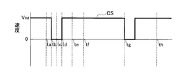
- FIG. 9A is a diagram illustrating an example of the processing speed in the X-axis direction at each point in the movement command signal.
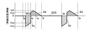
- FIG. 9B is a diagram illustrating an example of the speed in the X-axis direction at each point in the main movement command signal.
- FIG. 9C is a diagram illustrating an example of the speed in the X-axis direction at each time point in the sub-movement command signal.
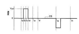
- FIG. 10A is a diagram illustrating an example of the machining speed in the Y-axis direction at each time point in the movement command signal.
- FIG. 9A is a diagram illustrating an example of the processing speed in the Y-axis direction at each time point in the movement command signal.
- FIG. 10B is a diagram illustrating an example of the speed in the Y-axis direction at each point in the main movement command signal.
- FIG. 10C is a diagram illustrating an example of the speed in the Y-axis direction at each point in the sub-movement command signal.
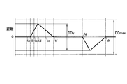
- FIG. 11 is a diagram illustrating an example of the distance between the nozzle center and the beam center at each point in the X-axis direction.
- FIG. 12 is a diagram illustrating an example of the distance between the nozzle center and the beam center at each point in the Y-axis direction.
- FIG. 13A is a diagram illustrating an example of a positional relationship between a nozzle center and a beam center at the time of processing.
- FIG. 13B is a diagram illustrating an example of the positional relationship between the nozzle center and the beam center at the time of processing.
- FIG. 13C is a diagram illustrating an example of a positional relationship between a nozzle center and a beam center at the time of processing.
- FIG. 13D is a diagram illustrating an example of the positional relationship between the nozzle center and the beam center at the time of processing.
- FIG. 13E is a diagram illustrating an example of the positional relationship between the nozzle center and the beam center at the time of processing.
- FIG. 13F is a diagram illustrating an example of the positional relationship between the nozzle center and the beam center at the time of processing.
- FIG. 13G is a diagram illustrating an example of the positional relationship between the nozzle center and the beam center at the time of processing.
- a laser processing machine 100 generates a laser beam and emits the laser beam, a laser processing unit 20, and transmits the laser beam emitted from the laser oscillator 10 to the laser processing unit 20.
- the laser beam machine 100 also includes an operation unit 40, an NC device 50, a machining program database 60, a machining condition database 70, and an assist gas supply device 80.
- the NC device 50 is an example of a control device that controls each unit (specifically, the laser oscillator 10, the laser processing unit 20, and the assist gas supply device 80) of the laser processing machine 100.
- the operation unit 40 outputs instruction information SF corresponding to the operation content to the NC device 50 when the operator operates the operation unit 40.
- the NC device 50 reads the machining program (NC data) PP from the machining program database 60 and the machining condition CP from the machining condition database 70 based on the instruction information SF.
- the NC device 50 reads the machining program PP corresponding to the product design model based on the instruction information SF from the machining program database 60.
- the processing program PP is a program for the laser processing machine 100 to execute the processing of the sheet metal W.
- the processing conditions CP include processing target information in which material parameters such as the material and thickness of the sheet metal W are specified.
- the processing conditions CP include processing parameters such as the output of the laser beam, the processing speed, the diameter (nozzle diameter) of the opening 36a of the nozzle 36 described later, and cutting processing information such as the assist gas conditions.
- the NC apparatus 50 reads the processing condition CP suitable for the product design model from the processing condition database 70.
- the NC device 50 controls the laser oscillator 10, the laser processing unit 20, and the assist gas supply device 80 based on the processing program PP and the processing conditions CP.
- the laser oscillator 10 a laser oscillator that amplifies pump light emitted from a laser diode and emits a laser beam of a predetermined wavelength or a laser oscillator that directly uses a laser beam emitted from a laser diode is preferable.
- the laser oscillator 10 is, for example, a solid-state laser oscillator, a fiber laser oscillator, a disk laser oscillator, or a direct diode laser oscillator (DDL oscillator).
- the laser oscillator 10 emits a 1 ⁇ m band laser beam having a wavelength of 900 nm to 1100 nm.
- the fiber laser oscillator emits a laser beam having a wavelength of 1060 nm to 1080 nm
- the DDL oscillator emits a laser beam having a wavelength of 910 nm to 950 nm.
- the laser processing unit 20 includes a processing table 21 on which a sheet metal W to be processed is placed, a gate-shaped X-axis carriage 22, a Y-axis carriage 23, a collimator unit 30 fixed to the Y-axis carriage 23, and a processing head. 35.
- the sheet metal W is made of, for example, stainless steel. The material and thickness of the sheet metal W are not particularly limited.
- the X-axis carriage 22 is configured to be movable on the processing table 21 in the X-axis direction.
- the Y-axis carriage 23 is configured to be movable on the X-axis carriage 22 in the Y-axis direction perpendicular to the X-axis.
- the X-axis carriage 22 and the Y-axis carriage 23 serve as a moving mechanism that moves the processing head 35 along the surface of the sheet metal W in the X-axis direction, the Y-axis direction, or any combined direction of the X-axis and the Y-axis. Function.
- the laser processing machine 100 may be configured so that the position of the processing head 35 is fixed and the sheet metal W moves.
- the laser processing machine 100 only needs to have a moving mechanism that moves the processing head 35 relative to the surface of the sheet metal W.
- the processing head 35 has a circular opening 36a at the tip, and a nozzle 36 for emitting a laser beam LB from the opening 36a is attached.
- the sheet metal W is irradiated with the laser beam LB emitted from the opening 36 a of the nozzle 36.
- the assist gas supply device 80 supplies the assist gas AG to the processing head 35.
- the assist gas supply device 80 supplies nitrogen to the processing head 35 as the assist gas AG if the sheet metal W is stainless steel and nitrogen if the sheet metal W is mild steel.
- the assist gas AG may be a mixed gas of nitrogen and oxygen, and the mixing ratio can be arbitrarily set depending on whether the purpose is to suppress oxidation or to utilize heat of oxidation reaction.
- the assist gas AG is blown onto the sheet metal W from the opening 36a.
- the assist gas AG discharges the molten metal in the kerf where the sheet metal W has melted.
- the collimator unit 30 includes a collimation lens 31 that converts the divergent laser beam LB emitted from the process fiber 12 into parallel light (collimated light).
- the collimator unit 30 includes a galvano scanner unit 32 and a bend mirror 33 that reflects the laser beam LB emitted from the galvano scanner unit 32 downward in the Z-axis direction perpendicular to the X-axis and the Y-axis.
- the processing head 35 includes a focusing lens 34 that focuses the laser beam LB reflected by the bend mirror 33 and irradiates the sheet metal W with the laser beam LB.
- the galvano scanner unit 32 includes a scan mirror 321 that reflects the laser beam LB emitted from the collimation lens 31, and a drive unit 322 that rotates the scan mirror 321 at a predetermined angle. Further, the galvano scanner unit 32 includes a scan mirror 323 that reflects the laser beam LB emitted from the scan mirror 321 and a drive unit 324 that rotates the scan mirror 323 to a predetermined angle.
- FIG. 3 shows the positional relationship between the laser beam LB and the opening 36a of the nozzle 36 in the reference state.
- Reference symbol BS indicates a beam spot at an irradiation position when the sheet metal W is irradiated with the laser beam LB.
- Symbol BC indicates the center of the beam spot BS.
- the center BC of the beam spot BS is referred to as a beam center BC.
- the laser beam machine 100 is centered so that the laser beam LB emitted from the opening 36a of the nozzle 36 is located at the center of the opening 36a.
- the center of the opening 36a coincides with the center of the nozzle 36.
- the center of the opening 36a and the center of the nozzle 36 are collectively referred to as a nozzle center NC.
- the beam center BC coincides with the nozzle center NC. Therefore, in the reference state, the laser beam LB is emitted from the nozzle center NC.
- the galvano scanner unit 32 functions as a beam displacement mechanism that travels inside the processing head 35 and displaces the position of the laser beam LB emitted from the opening 36a within the opening 36a.
- the drive units 322 and 324 can also cause the scan mirrors 321 and 323 to reciprocate in a predetermined angular range based on the control by the NC device 50, respectively.
- the galvano scanner unit 32 can vibrate the laser beam LB applied to the sheet metal W. That is, the NC device 50 can also cause the galvano scanner unit 32 to function as a beam vibration mechanism that vibrates the laser beam LB emitted from the opening 36a while traveling in the processing head 35 within the opening 36a.
- the NC apparatus 50 can displace the beam spot BS formed by irradiating the surface of the sheet metal W with the laser beam LB.
- the NC device 50 can vibrate the laser beam LB in a predetermined direction in the plane of the sheet metal W to vibrate a beam spot formed on the plane of the sheet metal W.
- the galvano scanner unit 32 is an example of a beam displacement mechanism and a beam vibration mechanism, and the beam displacement mechanism and the beam vibration mechanism are not limited to the galvano scanner unit 32.
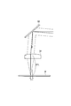
- FIG. 4 shows a state where one or both of the scan mirror 321 and the scan mirror 323 shown in FIG. 2 are tilted, and the position of the laser beam LB applied to the sheet metal W is displaced.
- a thin solid line bent by the bend mirror 33 and passing through the focusing lens 34 indicates the optical axis of the laser beam LB when the laser processing machine 100 is in the reference state.
- the angle of the optical axis of the laser beam LB incident on the bend mirror 33 changes by the operation of the galvano scanner unit 32 located in front of the bend mirror 33, and the optical axis is shifted to the center of the bend mirror 33. Get off.
- the incident position of the laser beam LB on the bend mirror 33 before and after the operation of the galvano scanner unit 32 is set to the same position.
- the galvano scanner unit 32 inclines the laser beam LB by the angle ⁇ in the direction opposite to the direction shown in FIG. 4, the irradiation position of the laser beam LB on the sheet metal W is shifted by the distance ⁇ s in the direction opposite to the direction shown in FIG. Can be displaced.
- FIG. 5 shows a positional relationship between the laser beam LB and the opening 36 a of the nozzle 36 in a state where the optical axis of the laser beam LB is displaced. That is, the distance ⁇ s is a distance between the nozzle center NC and the beam center BC at a position where the sheet metal W is irradiated with the laser beam LB (hereinafter, referred to as an irradiation position), and is a displacement amount of the beam center BC with respect to the nozzle center NC. Equivalent to.
- the displacement of the beam center BC with respect to the nozzle center NC is simply referred to as the displacement of the beam center BC.
- the displacement of the beam center BC at the opening 36a of the nozzle 36 is equal to the displacement of the beam center BC at the position where the sheet metal W is irradiated with the laser beam LB. That is, when the beam center BC at the opening 36a of the nozzle 36 is displaced by the distance ⁇ s with respect to the nozzle center NC, the beam center BC at the position where the sheet metal W is irradiated with the laser beam LB is also shifted by the distance ⁇ s with respect to the nozzle center NC. Displacement.
- the laser processing machine 100 can control the beam spot BS (laser beam LB). ) Can be displaced to process the sheet metal W. Specifically, assuming that the radius of the opening 36a is ra and the radius of the beam spot BS is rb, if the distance ⁇ s satisfies the relational expression ⁇ s + rb ⁇ ra, the laser processing machine 100 displaces the beam spot BS (laser beam LB). Thus, the sheet metal W can be processed. If the distance ⁇ s is not less than the radius of the opening 36a, the laser processing machine 100 processes the sheet metal W with the beam center BC coincident with the nozzle center NC.
- the assist gas is blown onto the sheet metal W from the opening 36a.
- the gas pressure and the flow rate of the assist gas are weak near the inner periphery with respect to the center of the opening 36a. Therefore, assuming that the distance obtained by subtracting the predetermined distance La from the radius ra of the opening 36a is the maximum distance, the distance ⁇ s is preferably equal to or less than the maximum distance. More specifically, the distance ⁇ s is preferably a value that satisfies the relational expression ⁇ s + rb ⁇ ra ⁇ La.
- the circle shown by the dashed line in FIG. 5 indicates the beam movement range in which the beam spot BS can be displaced.
- the laser beam machine 100 can cut and process the sheet metal W while blowing the assist gas at the target gas pressure and flow rate onto the sheet metal W. .
- the NC device 50 includes a movement control unit 501, a movement command division unit 503, a movement mechanism control unit 505, and a displacement control unit 506.
- the movement command dividing unit 503 includes a delay unit 5031, a low-pass filter (hereinafter, LPF) 5032, and a subtractor 5033.
- LPF low-pass filter
- FIGS. 6 to 7B An example of a processing method by the laser processing machine 100 will be described with reference to FIGS. 6 to 7B, flowcharts shown in FIGS. 8A to 8D, and FIGS. 9A to 13G.
- FIG. 7A shows the respective coordinate points Pa, Pb, Pc, Pd, and Pe of the cutout portion NS in FIG. 7A. That is, FIG. 7B shows each coordinate point in the processed shape of the sheet metal W.
- Time points tb, tf, tg, and th shown in FIGS. 9A to 9C and FIGS. 10A to 10C correspond to the time points at which the coordinate points Pb, Pc, Pd, and Pe shown in FIG. 7B are processed, respectively.
- the operation unit 40 when the operator operates the operation unit 40, the operation unit 40 outputs the instruction information SF based on the operation content to the NC device 50 in step S1.
- the movement control unit 501 reads the machining program PP from the machining program database 60 and the machining condition CP from the machining condition database 70 based on the instruction information SF in step S2.
- the movement control unit 501 generates a movement command signal CS including speed control information as shown in FIGS. 9A and 10A based on the machining program PP and the machining conditions CP in step S3.
- FIG. 9A shows the machining speed in the X-axis direction at each point in the movement command signal CS.
- FIG. 10A shows the machining speed in the Y-axis direction at each point in the movement command signal CS.
- the movement command signal CS sets the processing speed in the Y-axis direction to 0 and sets the processing speed in the X-axis direction to a predetermined speed Vxa based on the processing condition CP in a period from time tb and a period from time td to time tg. , A constant speed movement command for moving the machining position in the X-axis direction.
- the movement command signal CS sets the machining speed in the X-axis direction to 0, the machining speed in the Y-axis direction to a predetermined speed Vya based on the machining condition CP, and sets the machining position to Y in the period from time tb to time td. Includes a constant speed movement command to move in the axial direction.
- the movement command signal CS is a movement command signal for controlling the direction (machining direction) and speed (machining speed) of cutting the sheet metal W. Further, movement control section 501 outputs movement command signal CS to movement command division section 503.
- step S4 the movement control unit 501 acquires the coordinate information CF of the machining shape from the machining program PP.
- the movement control unit 501 determines the coordinate point Pa in the cutout portion NS as illustrated in FIG.
- the coordinate information CF including Pb, Pc, Pd, and Pe is acquired.
- the coordinate points Pa, Pb, Pc, Pd, and Pe are, for example, a coordinate point at which cutting is started and a coordinate point at which the cutting direction is switched.
- the coordinate information CF may include one or more coordinate points other than the above coordinate points.
- step S5 when processing the sheet metal W based on the processing program PP, the movement control unit 501 determines whether or not the laser beam LB is displaced within the area of the opening 36a of the nozzle 36 in the coordinate information CF. Judgment based on An example of a specific determination method in step S5 will be described with reference to FIG. 8B.
- the movement control section 501 calculates the distance D between coordinate points based on the coordinate information CF in step S51. For example, the movement control unit 501 calculates a distance Dbc from the coordinate point Pb to the coordinate point Pc as shown in FIG. 7B. The distance Dbc corresponds to a step of the cutout portion NS. In step S52, the movement control unit 501 determines whether the distance D between the coordinate points (specifically, the distance Dbc) falls within the area of the opening 36a.
- the movement control unit 501 determines in step S53 the distance Dbc, the processing speed, and the acceleration (deceleration) of the processing head 35. And the beam return distance BRD is calculated based on the amount (distance) of the change ( ⁇ s) of the beam spot BS in the section from the coordinate point Pb to the coordinate point Pc. That is, the movement control unit 501 determines the distance (distance between coordinate points) in a predetermined processing section, the processing speed, the acceleration (deceleration) of the processing head 35, and the amount by which the displacement amount of the beam spot BS has changed. The beam return distance BRD is calculated. Therefore, the movement control unit 501 acquires the beam return distance BRD in step S53. A specific method of calculating the beam return distance BRD will be described later.
- the beam return distance BRD is a distance required for processing the sheet metal W at a predetermined processing speed and returning the displaced beam spot BS to a predetermined position (for example, an initial setting position).
- the beam return distance BRD refers to the positional relationship between the beam spot BS and the processing head 35 (the beam center BC when the processing head 35 is moved without reducing the processing speed and the beam spot BS is displaced). This is the distance required until the position relationship between the position and the nozzle center NC returns to a predetermined state (for example, an initial setting state).
- the displacement of the beam spot BS changes according to the processing position.
- the amount by which the displacement amount of the beam spot BS has changed is a difference in the amount of displacement of the beam spot BS that has changed according to the processing position during processing (for example, a section from the coordinate point Pb to the coordinate point Pc). That is, the amount of change in the displacement amount of the beam spot BS is a difference distance in which the distance from the nozzle center NC to the beam center BC changes according to the processing position during processing.
- the laser beam machine 100 can return the beam spot BS to the initial setting state even during the processing by displacing the beam spot BS so as to be equal to or less than the beam return distance BRD during the processing.
- the beam return distance BRD may be set in advance in the processing condition CP. If the beam return distance BRD is set in advance to the processing condition CP, the movement control unit 501 acquires the beam return distance BRD from the processing condition CP in step S53.
- step S54 the movement control unit 501 calculates a distance Dcd from the next coordinate point Pc to the coordinate point Pd based on the coordinate information CF, as shown in FIG. 7B.
- step S55 the movement control unit 501 determines whether the distance Dcd is equal to or longer than the beam return distance BRD.
- step S54 If it is determined in step S54 that the distance Dcd is equal to or greater than the beam return distance BRD (YES), the movement command division unit 503 outputs the movement command signal CS to the delay unit 5031 and the LPF 5032. If it is determined in step S54 that the distance Dcd is equal to or greater than the beam return distance BRD (YES), the movement control unit 501 returns to step S54, and based on the coordinate information CF, the distance D () between the next coordinate points. For example, a distance Dde) from the coordinate point Pd to the coordinate point Pe is calculated. Further, in step S55, the movement control unit 501 determines whether or not the distance Dde is equal to or longer than the beam return distance BRD.
- step S6 the delay unit 5031 generates a delayed movement command signal DCS for delaying the movement command signal CS by a predetermined time, and outputs the signal to the subtractor 5033.
- the LPF 5032 executes a filtering process (Bessel filter process) that allows only the low frequency component of the movement command signal CS to pass in step S7, thereby obtaining the speed control information as shown in FIGS. 9B and 10B. Is generated.
- FIG. 9B shows the velocity in the X-axis direction at each point in the main movement command signal MCS.
- FIG. 10B shows the velocity in the Y-axis direction at each point in the main movement command signal MCS.
- the main movement command signal MCS is a movement command signal for controlling the moving direction and the moving speed of the processing head 35 (nozzle center NC).
- the main movement command signal MCS sets the moving speed in the Y-axis direction to 0 and sets the moving speed in the X-axis direction to a predetermined speed Vxa based on the machining condition CP during a period from time tb and a period from time tf to time tg.
- the main movement command signal MCS changes the moving speed of the machining head 35 in the X-axis direction from a predetermined speed Vxa based on the machining condition CP during a period from time tb to time tf.
- the main movement command signal MCS moves the machining head 35 in the Y-axis direction from a moving speed of 0 to a predetermined speed Vyb based on the machining condition CP during a period from time tb to time tf. And a deceleration command for decelerating the speed from Vyb to zero.
- the processing direction from the coordinate point Pb to the coordinate point Pc is the same as the processing direction from the coordinate point Pd to the coordinate point Pe. Therefore, as shown in FIG. 9B, the speed profile in the period from time tb to time tf is the same as the speed profile in the period from time tg to time th.
- the processing direction from the coordinate point Pb to the coordinate point Pc and the processing direction from the coordinate point Pd to the coordinate point Pe are opposite to each other. Therefore, as shown in FIG. 10B, the speed profile in the period from the time point tb to the time point tf and the speed profile in the period from the time point tg to the time point th have a relationship in which the sign is inverted.
- the main movement command signal MCS is used to move the processing head 35 in the X-axis direction, the Y-axis direction, or an arbitrary combined direction of the X-axis and the Y-axis, and to process each section at the coordinate points Pa to Pe.
- This is a movement command signal for controlling the moving speed of the head 35.
- the LPF 5032 outputs the main movement command signal MCS to the subtractor 5033 and the movement mechanism control unit 505. Accordingly, the subtractor 5033 receives the delayed movement command signal DCS from the delay device 5031 and the main movement command signal MCS from the LPF 5032.
- the movement control unit 501 calculates the distance Sa based on the time from time tb to time td, the processing speed, and the deceleration of the processing head 35.
- the movement control unit 501 calculates the beam return distance BRD based on the time from time td to time tf, the processing speed, the deceleration and the acceleration of the processing head 35. Therefore, the movement control unit 501 acquires the beam return distance BRD.
- the subtractor 5033 subtracts the main movement command signal MCS from the delayed movement command signal DCS in step S8, thereby obtaining the sub movement command signal SCS including the speed control information as shown in FIGS. 9C and 10C.
- FIG. 9C shows the velocity in the X-axis direction at each time point in the sub-movement command signal SCS.
- FIG. 10C shows the speed in the Y-axis direction at each time point in the sub-movement command signal SCS.
- the velocities in the X-axis direction and the Y-axis direction at each point in the sub-movement command signal SCS are shown as relative velocities of the beam center BC with respect to the nozzle center NC.
- the sub-movement command signal SCS is a movement command signal for controlling the moving direction and the moving speed of the beam spot BS (beam center BC), and is used to control the beam center BC (beam spot BS) with respect to the nozzle center NC (processing head 35). This is a movement command signal for controlling the displacement direction and the displacement speed.
- the sub-movement command signal SCS sets the relative speed (displacement speed) of the beam center BC with respect to the nozzle center NC to 0 during the period from time tb and from time tf to time tg. That is, a constant speed movement command for moving the beam spot BS (beam center BC) in the X-axis direction at the same speed Vxa as the processing head 35 is included.
- the sub-movement command signal SCS instantaneously switches the relative speed of the beam spot BS from the speed 0 to the speed Vxc in the X-axis direction and the speed 0 to the speed Vyc in the Y-axis direction at the time tb. Includes a speed switching command to switch.
- the speed Vxc is a negative speed in the X-axis direction
- the speed Vyc is a positive speed in the Y-axis direction.
- the sub-movement command signal SCS is an acceleration command for accelerating the beam spot BS from the speed Vxc to a speed Vxd higher than the speed Vxc in the X-axis direction during the period from the time tb to the time td.
- a deceleration command for decelerating the relative speed from the speed Vyc to a speed Vyd lower than the speed Vyc in the Y-axis direction.
- the speed Vxd is a negative speed in the X-axis direction
- the speed Vyd is a positive speed in the Y-axis direction.
- the sub-movement command signal SCS instantaneously switches the relative speed of the beam spot BS from the speed Vxd to the speed Vxe in the X-axis direction, and instantaneously changes from the speed Vyd to the speed Vye in the Y-axis direction. Includes a speed switching command to switch.
- the speed Vxe is a positive speed in the X-axis direction
- the speed Vye is a negative speed in the Y-axis direction.
- the acceleration (deceleration) of the beam spot BS (beam center BC) by the galvano scanner unit 32 is orders of magnitude larger than the acceleration (deceleration) of the processing head 35 (nozzle center NC). Therefore, the time during which the beam spot BS accelerates or decelerates is negligibly short compared to the time when the processing head 35 accelerates or decelerates.
- FIGS. 9C and 10C show that the speed (relative speed) is instantaneously switched at time points tb and td.
- the delay time of the delayed movement command signal DCS with respect to the movement command signal CS is negligibly short. Therefore, in FIGS. 9A and 10A, the movement command signal CS and the delayed movement command signal DCS are set to the same speed. Shown in profile.
- the relative speed of the beam spot BS is changed from the speed Vxe to the speed Vxf higher than the speed Vxe in the X-axis direction during the period from the time td to the time tf.
- the speed Vxf is a positive speed in the X-axis direction.
- the processing direction from the coordinate point Pb to the coordinate point Pc is the same as the processing direction from the coordinate point Pd to the coordinate point Pe. Therefore, as shown in FIG. 9C, the speed profile in the period from time tb to time tf is the same as the speed profile in the period from time tg to time th.
- the relative speed of the beam spot BS is changed from the speed Vye to the speed Vyf lower than the speed Vye in the Y-axis direction during the period from the time td to the time tf.
- the speed Vyf is a negative speed in the Y-axis direction.
- the processing direction from the coordinate point Pb to the coordinate point Pc and the processing direction from the coordinate point Pd to the coordinate point Pe are opposite to each other. Therefore, as shown in FIG. 10C, the speed profile in the period from time tb to time tf and the speed profile in the period from time tg to time th have a relationship in which the sign is inverted.
- the distance Sc shown in FIG. 9C is the amount of change in the displacement of the beam spot BS in the section from the coordinate point Pb to the coordinate point Pc, and the displacement of the beam spot BS at the coordinate point Pb and the beam spot BS at the coordinate point Pc. Is equivalent to the difference from the displacement amount.
- the distance Sc corresponds to the difference between the distance from the nozzle center NC at the coordinate point Pb to the beam center BC and the distance from the nozzle center NC to the beam center BC at the coordinate point Pc.
- the distance Sd is the amount by which the displacement of the beam spot BS has changed in the section from the coordinate point Pc to the coordinate point corresponding to the time point tf at which the beam spot BS returns to a predetermined state (for example, the initial setting state).
- the distance Sa shown in FIG. 9B, the distance Se shown in FIG. 10B, and the distance Sg shown in FIG. 10C are equal to the distance Sc shown in FIG. 9C.
- the distance Sb shown in FIG. 9B, the distance Sf shown in FIG. 10B, and the distance Sh shown in FIG. 10C are equal to the distance Sd shown in FIG. 9C.
- the subtractor 5033 outputs the sub-movement command signal SCS to the displacement control unit 506.
- FIGS. 11 and 12 show the distance (displacement amount of the beam center BC) between the nozzle center NC and the beam center BC at each time point in the X-axis direction and the Y-axis direction, respectively.
- Reference sign DDx shown in FIG. 11 indicates the maximum change amount of the distance between the nozzle center NC and the beam center BC in the X-axis direction, that is, the maximum change amount of the displacement amount of the beam center BC in the X-axis direction.
- Reference sign DDy shown in FIG. 12 indicates the maximum change amount of the distance between the nozzle center NC and the beam center BC in the Y-axis direction, that is, the maximum change amount of the displacement amount of the beam center BC in the Y-axis direction.
- the moving mechanism including the X-axis carriage 22 and the Y-axis carriage 23 has driving units 220 and 230 for driving the X-axis carriage 22 and the Y-axis carriage 23, respectively.
- the moving mechanism control unit 505 moves the processing head 35 by controlling the driving units 220 and 230 based on the main movement command signal MCS in step S9.
- the displacement control unit 506 drives the driving units 322 and 324 of the galvano scanner unit 32 based on the sub-movement command signal SCS to displace the beam spot BS.
- step S5 shown in FIG. 8A it is determined in step S5 shown in FIG. 8A that the laser beam LB is not displaced (NO) in the area of the opening 36a of the nozzle 36.
- step S52 shown in FIG. 8B the distance D between the coordinate points is reduced to the opening 36a. Is determined to be outside the area (No), or when it is determined in step S55 that the distance D between the coordinate points P is not greater than or equal to the beam return distance BRD (No).
- step S5 shown in FIG. 8A If it is determined in step S5 shown in FIG. 8A that the laser beam LB is not displaced in the area of the opening 36a of the nozzle 36 (NO), the LPF 5032 in FIG. , A filtering process (Bessel filter process) for passing only the low frequency components is performed.
- the LPF 5032 generates a main movement command signal MCS including speed control information as shown in FIGS. 9B and 10B by the above-described filtering process.
- Step S17 corresponds to step S7.
- the laser processing machine 100 processes the sheet metal W by moving the processing head 35 based on the processing program PP and the processing conditions CP while keeping the beam center BC coincident with the nozzle center NC.
- FIGS. 10A to 10C the processing head 35 and the beam spot BS when the sheet metal W is cut with the cutout portion NS as shown in FIG. 7A. Will be described.
- FIGS. 13A to 13G show the positional relationship between the nozzle center NC (working head 35) and the beam center BC (beam spot BS) at the time points ta to tg in FIGS. 9A to 9C and 10A to 10C, respectively. Is shown. More specifically, FIG. 13A shows time t, FIG. 13B shows time tb, FIG. 13C shows time tc, FIG. 13D shows time td, FIG. 13E shows time te, FIG. 13F shows time tf, and FIG. This shows the processing position.
- the beam spot BS (laser beam LB) is set such that a position where the beam center BC is displaced in the X-axis direction by a predetermined displacement DAx with respect to the nozzle center NC becomes an initial setting position.
- the processing head 35 is moving in the X-axis direction at the speed Vxa with the beam spot BS displaced in the X-axis direction by the displacement DAx.
- the beam center BC reaches the coordinate point Pb.
- the processing head 35 changes the moving direction at time tb from the X-axis direction to the combined direction of the X-axis and the Y-axis, starts deceleration in the X-axis direction, and accelerates in the Y-axis direction.
- the movement direction of the beam spot BS changes from the X-axis direction to the Y-axis direction at time tb.
- the relative speed of the beam center BC with respect to the nozzle center NC is changed from the speed 0 to the speed Vxc in the X-axis direction, and is changed from the speed 0 to the speed Vyc in the Y-axis direction.
- the beam spot BS starts displacing with respect to the initial setting position at time tb.
- the distance between the beam center BC and the nozzle center NC is changed so as to be shorter in the X-axis direction at time tb and longer in the Y-axis direction. Be changed. That is, at the time point tb, the beam center BC starts displacement in a direction approaching the nozzle center NC in the X-axis direction, and starts displacement in a direction away from the nozzle center NC in the Y-axis direction. .
- the processing head 35 changes the moving direction to the combined direction of the X axis and the Y axis according to the processing position, and continues deceleration in the X axis direction. , In the Y-axis direction.
- the beam spot BS is moving in the Y-axis direction from the coordinate point Pb toward the coordinate point Pc, and the displacement amount is changed according to the processing position.
- the beam center BC reaches the coordinate point Pc.
- the processing head 35 changes the moving direction to the combined direction of the X axis and the Y axis according to the processing position, and continues deceleration in the X axis direction, Continues to accelerate.
- the movement direction of the beam spot BS is changed from the Y-axis direction to the X-axis direction at time tc, and the displacement amount is changed according to the processing position.
- the relative speed of the beam center BC with respect to the nozzle center NC is changed from the speed Vxd to the speed Vxe in the X-axis direction, and is changed from the speed Vyd to the speed Vye in the Y-axis direction.
- the displacement of the beam spot BS becomes maximum with respect to the initial setting position. That is, the displacement amount of the beam spot BS becomes the maximum change amounts DDx and DDy of the beam center BC in the X-axis direction and the Y-axis direction at the time point td.
- the laser beam LB (beam spot BS) can be displaced within a beam movement range indicated by the distance DDmax.
- the processing head 35 starts accelerating after deceleration in the X-axis direction, and decelerates after accelerating in the Y-axis direction.
- the processing head 35 changes the moving direction to the combined direction of the X axis and the Y axis according to the processing position, and continues to accelerate in the X axis direction.
- the beam spot BS is moving in the X-axis direction from the coordinate point Pc toward the coordinate point Pd, and the displacement amount is changed according to the processing position.
- the processing head 35 moves in the direction in which the X axis and the Y axis are combined, and the beam spot BS (laser beam LB) has the beam center BC at the coordinate points Pc and Pd. And return to the initial setting position.
- the relative speed of the beam center BC with respect to the nozzle center NC is 0 in the X-axis direction and the Y-axis direction.
- the processing head 35 and the beam spot BS are on the same line on the line connecting the coordinate points Pa and Pb with the beam center BC displaced in the X-axis direction by the displacement DAx with respect to the nozzle center NC. Move on the trajectory.
- the processing head 35 and the beam spot BS maintain the state where the beam center BC is displaced in the X-axis direction by the displacement amount DAx with respect to the nozzle center NC, and the coordinate point Pa and the coordinate point It moves on the same trajectory on the line connecting Pb.
- the period up to the time point tb corresponds to a section up to the coordinate point Pb.
- the processing head 35 moves in the synthesis direction of the X-axis and the Y-axis according to the processing position, so that the inside of the apex (coordinate point Pc) of the cutout portion NS is located. Move on the trajectory that passes.
- the beam spot BS is displaced while changing the displacement amount with respect to the initial setting position in accordance with the processing position, and on the line connecting the coordinate points Pa and Pb, the coordinate point It sequentially moves on a line connecting Pb and the coordinate point Pc and on a line connecting the coordinate point Pc and the coordinate point Pd.
- the beam center BC reaches the coordinate point Pd.
- the processing head 35 changes the moving direction from the X-axis direction to the combined direction of the X-axis and the Y-axis, starts deceleration in the X-axis direction, and accelerates in the Y-axis direction.
- the beam spot BS changes its moving direction from the X-axis direction to the Y-axis direction (specifically, the ⁇ Y-axis direction) at time tb.
- the machining direction after time tb and the machining direction after time tg are opposite to each other.
- the speed profile of the processing head 35 during the period from the time point tb to the time point tf and the speed profile of the processing head 35 during the period from the time point tg to the time point th have opposite signs. become.
- the speed profile of the beam spot BS in the period from time tb to time tf and the speed profile of the beam spot BS in the period from time tg to time th have opposite signs. Become a relationship.
- the laser processing machine 100 and its laser processing method when processing the sheet metal W, it is determined whether or not the laser beam LB is displaced within the area of the opening 36 a of the nozzle 36.
- the moving direction of the machining head 35 at the coordinate points Pb and Pc is continuously changed.
- the amount of change in the moving speed of the processing head 35 can be suppressed, and the sheet metal W can be processed with high accuracy without changing (decelerating) the processing speed.
- the sheet metal W is cut by bending the cutting progress direction at a corner portion that is equal to or less than a predetermined angle, or the cutting direction is sharply changed to make the sheet metal W curved. Even in the case of cutting, the sheet metal W can be cut faster than in the past, and the processing time can be shortened.
- the laser beam machine 100 and its laser beam machining method when machining the sheet metal W, it is determined whether or not the distance between coordinate points is equal to or longer than the beam return distance BRD. In the laser beam machine 100 and its laser beam machining method, it is determined whether or not the beam spot BS can return to the initial setting position while the sheet metal W is being machined. Therefore, when the beam spot BS can return to the initial setting position, the laser processing machine 100 can process the sheet metal W by displacing the beam spot BS with respect to the initial setting position.
- the laser processing machine 100 fixes the beam spot BS to the initial setting position.
- the sheet metal W is processed in the state. That is, according to the laser processing machine 100 and the laser processing method thereof, the processing method can be changed according to the displacement state of the beam spot BS during the processing of the sheet metal W.
- the laser beam machine 100 In the laser beam machine 100 and its laser beam machining method, if the distance between coordinate points is not longer than the beam return distance BRD, it may be determined whether the distance between the next coordinate points is longer than the beam return distance BRD. If the distance between the next coordinate points is greater than or equal to the beam return distance BRD, the laser beam machine 100 can proceed from step S5 to step S6.
- the present invention is not limited to one or more embodiments described above, and can be variously changed without departing from the gist of the present invention.
Landscapes
- Physics & Mathematics (AREA)
- Engineering & Computer Science (AREA)
- Optics & Photonics (AREA)
- Plasma & Fusion (AREA)
- Mechanical Engineering (AREA)
- Laser Beam Processing (AREA)
Abstract
レーザ加工機(100)は加工ヘッド(35)、移動機構(22及び23)、ビーム変位機構(32)、移動制御部(501)、移動指令分割部(503)、移動機構制御部(505)、変位制御部(506)を備える。移動制御部(501)は移動指令信号(CS)を生成し、座標情報(CF)に基づいてレーザビーム(LB)がノズル(36)の開口部(36a)の領域内で変位するか否かを判定する。レーザビーム(LB)が開口部(36a)の領域内で変位すると判定された場合、移動指令分割部(503)は移動指令信号(CS)に基づいて主移動指令信号(MCS)と副移動指令信号(SCS)とを生成する。移動機構制御部(505)は主移動指令信号(MCS)に基づいて移動機構(22及び23)を制御する。変位制御部(506)は副移動指令信号(SCS)に基づいてビーム変位機構(32)を制御する。
Description
本開示は、レーザビームによって板金を加工するレーザ加工機及びレーザ加工方法に関する。
レーザ発振器より射出されたレーザビームによって板金を切断して、所定の形状を有する製品を製作するレーザ加工機が普及している。レーザ加工機は、加工ヘッドの移動機構によって加工ヘッドを板金の面に沿って移動させて、板金を所定の形状に切断する。
移動している加工ヘッドが停止する減速時、または、停止状態にある加工ヘッドが移動を開始する加速時には、大きなイナーシャが発生する。従って、例えば切断進行方向を直角に曲げて板金を切断するときには、加工ヘッドの所定の移動速度(切断速度)を維持したまま角部を切断することはできない。そこで、レーザ加工機は、切断進行方向を所定の角度以下の角度で曲げて板金を切断するときには、角部で加工ヘッドを一旦停止または大幅に減速させた後に加工ヘッドの移動方向を変更する必要がある。レーザ加工機が、ヘアピン形状のように切断進行方向を急激に変更して板金を曲線状に切断する場合も同様である。
レーザ加工機が切断進行方向を所定の角度以下の角部で曲げて板金を切断したり、切断進行方向を急激に変更して板金を曲線状に切断したりするときには、板金を高速に切断できないので加工時間が長くなってしまう。レーザ加工機がそのような形状を切断する場合でも、板金をできるだけ高速に切断して加工時間を短くすることが求められる。
1またはそれ以上の実施形態は、切断進行方向を所定の角度以下の角部で曲げて板金を切断したり、切断進行方向を急激に変更して板金を曲線状に切断したりする場合でも、従来よりも板金を高速に切断することができ、加工時間を短くすることができるレーザ加工機及びレーザ加工方法を提供することを目的とする。
1またはそれ以上の実施形態の第1の態様によれば、先端部に円形の開口部を有し、前記開口部より板金を切断加工するためのレーザビームを射出するノズルが取り付けられている加工ヘッドと、前記板金の面に対して前記加工ヘッドを相対的に移動させる移動機構と、前記レーザビームが前記板金に照射されたときの照射位置におけるビームスポットの中心であるビーム中心を前記ノズルの中心であるノズル中心に対して変位させるビーム変位機構と、前記板金を切断する加工方向及び加工速度を制御するための移動指令信号を生成し、かつ、前記板金の加工形状の座標情報を取得し、前記座標情報に基づいて前記レーザビームが前記開口部の領域内で変位するか否かを判定する移動制御部と、前記レーザビームが前記開口部の領域内で変位すると判定された場合に、前記移動指令信号に基づいて、前記加工ヘッドの移動方向及び移動速度を制御するための主移動指令信号、及び、前記ビームスポットの移動方向及び移動速度を制御するための副移動指令信号を生成する移動指令分割部と、前記主移動指令信号に基づいて、前記加工ヘッドを相対的に移動させるよう前記移動機構を制御する移動機構制御部と、前記副移動指令信号に基づいて、前記ビーム中心が前記ノズル中心に対して変位するよう前記ビーム変位機構を制御する変位制御部とを備えるレーザ加工機が提供される。
1またはそれ以上の実施形態の第2の態様によれば、先端部に円形の開口部を有し、前記開口部より板金を切断加工するためのレーザビームを射出するノズルが取り付けられている加工ヘッドを備えるレーザ加工機が、前記板金を切断する加工方向及び加工速度を制御するための移動指令信号を生成し、前記板金の加工形状の座標情報を取得し、前記座標情報に基づいて前記レーザビームが前記開口部の領域内で変位するか否かを判定し、前記レーザビームが前記開口部の領域内で変位すると判定された場合に、前記移動指令信号に基づいて、前記加工ヘッドの移動方向及び移動速度を制御するための主移動指令信号、及び、前記レーザビームが前記板金に照射されたときの照射位置におけるビームスポットの移動方向及び移動速度を制御するための副移動指令信号を生成し、前記主移動指令信号に基づいて前記加工ヘッドを相対的に移動させ、かつ、前記副移動指令信号に基づいて前記ビームスポットの中心であるビーム中心を前記ノズルの中心であるノズル中心に対して変位させて前記板金を切断するレーザ加工方法が提供される。
1またはそれ以上の実施形態のレーザ加工機及びレーザ加工方法によれば、切断進行方向を所定の角度以下の角部で曲げて板金を切断したり、切断進行方向を急激に変更して板金を曲線状に切断したりする場合でも、従来よりも板金を高速に切断することができ、加工時間を短くすることができる。
以下、1またはそれ以上の実施形態のレーザ加工機及びレーザ加工方法について、添付図面を参照して説明する。
図1に示すように、レーザ加工機100は、レーザビームを生成して射出するレーザ発振器10と、レーザ加工ユニット20と、レーザ発振器10より射出されたレーザビームをレーザ加工ユニット20へと伝送するプロセスファイバ12とを備える。
また、レーザ加工機100は、操作部40と、NC装置50と、加工プログラムデータベース60と、加工条件データベース70と、アシストガス供給装置80とを備える。NC装置50は、レーザ加工機100の各部(具体的にはレーザ発振器10、レーザ加工ユニット20、及び、アシストガス供給装置80)を制御する制御装置の一例である。
操作部40は、オペレータが操作部40を操作することにより、操作内容に応じた指示情報SFをNC装置50へ出力する。NC装置50は、指示情報SFに基づいて、加工プログラムデータベース60から加工プログラム(NCデータ)PPを読み出し、加工条件データベース70から加工条件CPを読み出す。
具体的には、NC装置50は、指示情報SFに基づく製品の設計モデルに対応する加工プログラムPPを加工プログラムデータベース60から読み出す。加工プログラムPPは、レーザ加工機100が板金Wの加工を実行するためのプログラムである。加工条件CPには、板金Wの材質及び厚さ等の材料パラメータが指定された加工対象情報が含まれている。また、加工条件CPには、レーザビームの出力、加工速度、後述するノズル36の開口部36aの直径(ノズル径)等の加工パラメータ、及びアシストガス条件等の切削加工情報が含まれている。
NC装置50は、製品の設計モデルに適した加工条件CPを加工条件データベース70から読み出す。NC装置50は、加工プログラムPP及び加工条件CPに基づいて、レーザ発振器10、レーザ加工ユニット20及びアシストガス供給装置80を制御する。
レーザ発振器10としては、レーザダイオードより発せられる励起光を増幅して所定の波長のレーザビームを射出するレーザ発振器、または、レーザダイオードより発せられるレーザビームを直接利用するレーザ発振器が好適である。レーザ発振器10は、例えば、固体レーザ発振器、ファイバレーザ発振器、ディスクレーザ発振器、ダイレクトダイオードレーザ発振器(DDL発振器)である。
レーザ発振器10は、波長900nm~1100nmの1μm帯のレーザビームを射出する。ファイバレーザ発振器及びDDL発振器を例とすると、ファイバレーザ発振器は、波長1060nm~1080nmのレーザビームを射出し、DDL発振器は、波長910nm~950nmのレーザビームを射出する。
レーザ加工ユニット20は、加工対象物である板金Wを載せる加工テーブル21と、門型のX軸キャリッジ22と、Y軸キャリッジ23と、Y軸キャリッジ23に固定されたコリメータユニット30と、加工ヘッド35とを有する。板金Wは例えばステンレス鋼よりなる。板金Wの材料及び板厚は特に限定されない。
X軸キャリッジ22は、加工テーブル21上でX軸方向に移動自在に構成されている。Y軸キャリッジ23は、X軸キャリッジ22上でX軸に垂直なY軸方向に移動自在に構成されている。X軸キャリッジ22及びY軸キャリッジ23は、加工ヘッド35を板金Wの面に沿って、X軸方向、Y軸方向、または、X軸とY軸との任意の合成方向に移動させる移動機構として機能する。
レーザ加工機100は、加工ヘッド35を板金Wの面に沿って移動させる代わりに、加工ヘッド35は位置が固定されていて、板金Wが移動するように構成されていてもよい。レーザ加工機100は、板金Wの面に対して加工ヘッド35を相対的に移動させる移動機構を備えていればよい。
加工ヘッド35には、先端部に円形の開口部36aを有し、開口部36aよりレーザビームLBを射出するノズル36が取り付けられている。ノズル36の開口部36aより射出されたレーザビームLBは板金Wに照射される。
アシストガス供給装置80は、アシストガスAGを加工ヘッド35に供給する。アシストガス供給装置80は、板金Wがステンレス鋼であれば窒素を、板金Wが軟鋼であれば酸素をアシストガスAGとして加工ヘッド35に供給する。アシストガスAGは、窒素と酸素との混合ガスでもよく、その目的が酸化抑制なのか、酸化反応熱を利用するのかによって、混合比を任意に設定できる。板金Wの加工時に、アシストガスAGは開口部36aより板金Wへと吹き付けられる。アシストガスAGは、板金Wが溶融したカーフ内の溶融金属を排出する。
図2に示すように、コリメータユニット30は、プロセスファイバ12より射出された発散光のレーザビームLBを平行光(コリメート光)に変換するコリメーションレンズ31を備える。また、コリメータユニット30は、ガルバノスキャナユニット32と、ガルバノスキャナユニット32より射出されたレーザビームLBをX軸及びY軸に対して垂直なZ軸方向下方に向けて反射させるベンドミラー33とを備える。加工ヘッド35は、ベンドミラー33で反射したレーザビームLBを集束して、板金Wに照射する集束レンズ34を備える。
ガルバノスキャナユニット32は、コリメーションレンズ31より射出されたレーザビームLBを反射するスキャンミラー321と、スキャンミラー321を所定の角度となるように回転させる駆動部322とを有する。また、ガルバノスキャナユニット32は、スキャンミラー321より射出されたレーザビームLBを反射するスキャンミラー323と、スキャンミラー323を所定の角度となるように回転させる駆動部324とを有する。
図3は、基準状態におけるレーザビームLBとノズル36の開口部36aとの位置関係を示している。符号BSは、レーザビームLBが板金Wに照射されたときの照射位置におけるビームスポットを示す。符号BCは、ビームスポットBSの中心を示す。以下、ビームスポットBSの中心BCをビーム中心BCとする。
レーザ加工機100は、ノズル36の開口部36aより射出されるレーザビームLBが開口部36aの中心に位置するように芯出しされている。開口部36aの中心とノズル36の中心とは一致している。以下、開口部36aの中心とノズル36の中心とを総称して、ノズル中心NCとする。基準の状態では、ビーム中心BCはノズル中心NCと一致している。従って、基準状態では、レーザビームLBは、ノズル中心NCより射出する。ガルバノスキャナユニット32は、加工ヘッド35内を進行して開口部36aより射出されるレーザビームLBの開口部36a内での位置を変位させるビーム変位機構として機能する。
駆動部322及び324は、NC装置50による制御に基づき、それぞれ、スキャンミラー321及び323を所定の角度範囲で往復振動させることもできる。スキャンミラー321とスキャンミラー323とのいずれか一方または双方を往復振動させることによって、ガルバノスキャナユニット32は、板金Wに照射されるレーザビームLBを振動させることができる。即ち、NC装置50は、ガルバノスキャナユニット32を、加工ヘッド35内を進行して開口部36aより射出されるレーザビームLBを、開口部36a内で振動させるビーム振動機構として機能させることもできる。
NC装置50は、ガルバノスキャナユニット32の駆動部322及び324を制御することによって、レーザビームLBが板金Wの面上に照射されることにより形成されるビームスポットBSを変位させることができる。また、NC装置50は、レーザビームLBを板金Wの面内の所定の方向に振動させて、板金Wの面上に形成されるビームスポットを振動させることができる。ガルバノスキャナユニット32はビーム変位機構及びビーム振動機構の一例であり、ビーム変位機構及びビーム振動機構はガルバノスキャナユニット32に限定されない。
図4は、図2に示すスキャンミラー321及びスキャンミラー323のいずれか一方または双方が傾けられて、板金Wに照射されるレーザビームLBの位置が変位した状態を示している。図4において、ベンドミラー33で折り曲げられて集束レンズ34を通過する細実線は、レーザ加工機100が基準の状態であるときのレーザビームLBの光軸を示している。
なお、詳細には、ベンドミラー33の手前に位置しているガルバノスキャナユニット32の作動により、ベンドミラー33に入射するレーザビームLBの光軸の角度が変化し、光軸がベンドミラー33の中心から外れる。図4では、簡略化のため、ガルバノスキャナユニット32の作動前後でベンドミラー33へのレーザビームLBの入射位置を同じ位置としている。
ガルバノスキャナユニット32による作用によって、レーザビームLBの光軸が細実線で示す位置から太実線で示す位置へと変位したとする。ベンドミラー33で反射するレーザビームLBが角度θで傾斜したとすると、板金WへのレーザビームLBの照射位置は距離Δsだけ変位する。集束レンズ34の焦点距離をEFL(Effective Focal Length)とすると、距離Δsは、関係式Δs=EFL×sinθにより算出することができる。
ガルバノスキャナユニット32がレーザビームLBを図4に示す方向とは逆方向に角度θだけ傾ければ、板金WへのレーザビームLBの照射位置を図4に示す方向とは逆方向に距離Δsだけ変位させることができる。
図5は、レーザビームLBの光軸を変位させた状態におけるレーザビームLBとノズル36の開口部36aとの位置関係を示している。即ち、距離Δsは、板金WにレーザビームLBが照射される位置(以下、照射位置とする)におけるノズル中心NCとビーム中心BCとの距離であり、ノズル中心NCに対するビーム中心BCの変位量に相当する。以下、ノズル中心NCに対するビーム中心BCの変位量を、単に、ビーム中心BCの変位量とする。
ノズル36の開口部36aにおけるビーム中心BCの変位量と、板金WへのレーザビームLBの照射位置におけるビーム中心BCの変位量とは等しいものとする。即ち、ノズル36の開口部36aにおけるビーム中心BCがノズル中心NCに対して距離Δsだけ変位する場合に、板金WへのレーザビームLBの照射位置におけるビーム中心BCもノズル中心NCに対して距離Δsだけ変位するものとする。
図5に示すように、ビーム中心BCの変位量(レーザビームLBの変位量)に相当する距離Δsが開口部36aの半径未満であれば、レーザ加工機100は、ビームスポットBS(レーザビームLB)を変位させて板金Wを加工することができる。詳しくは、開口部36aの半径をraとし、ビームスポットBSの半径をrbとすると、距離Δsが関係式Δs+rb<raを満たせば、レーザ加工機100は、ビームスポットBS(レーザビームLB)を変位させて板金Wを加工することができる。なお、距離Δsが開口部36aの半径未満でなければ、レーザ加工機100は、ビーム中心BCをノズル中心NCと一致させた状態で板金Wを加工する。
板金Wの加工時に、アシストガスは開口部36aより板金Wへと吹き付けられる。アシストガスは、開口部36aの中心部に対して内周付近ではガス圧及び流量が弱くなる。そのため、開口部36aの半径raから所定の距離Laだけ減算した距離を最大距離としたとき、距離Δsは最大距離以下の値であることが好ましい。詳しくは、距離Δsは、関係式Δs+rb<ra-Laを満たす値であることが好ましい。
図5に一点鎖線で示す円は、ビームスポットBSを変位させることができるビーム移動範囲を示している。レーザ加工機100は、一点鎖線で示すビーム移動範囲内でビームスポットBSを変位させることにより、目的のガス圧及び流量のアシストガスを板金Wへと吹き付けながら、板金Wを切断加工することができる。
図6に示すように、NC装置50は、移動制御部501、移動指令分割部503、移動機構制御部505、及び変位制御部506を備える。移動指令分割部503は、遅延器5031、ローパスフィルタ(以下、LPF)5032、及び減算器5033を有する。
図6~図7B、図8A~図8Dに示すフローチャート、及び図9A~図13Gを用いて、レーザ加工機100による加工方法の一例を説明する。
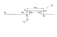
具体的には、図7Aに示すように、板金Wを切り欠き部NSを有する加工形状に切断する加工方法の一例を説明する。図7Bは、図7Aにおける切り欠き部NSの各座標点Pa、Pb、Pc、Pd、及びPeを示している。即ち、図7Bは、板金Wの加工形状における各座標点を示している。図9A~図9C、及び図10A~図10Cに示す時点tb、tf、tg、及びthは、それぞれ、図7Bに示す座標点Pb、Pc、Pd、及びPeを加工する時点に相当する。
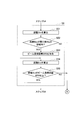
図8Aにおいて、オペレータが操作部40を操作することにより、操作部40は、ステップS1にて、操作内容に基づいた指示情報SFをNC装置50へ出力する。移動制御部501は、ステップS2にて、指示情報SFに基づいて、加工プログラムデータベース60から加工プログラムPPを読み出し、加工条件データベース70から加工条件CPを読み出す。
移動制御部501は、ステップS3にて、加工プログラムPP及び加工条件CPに基づいて、図9A及び図10Aに示すような速度制御情報を含む移動指令信号CSを生成する。図9Aは、移動指令信号CSにおける各時点のX軸方向の加工速度を示している。図10Aは、移動指令信号CSにおける各時点のY軸方向の加工速度を示している。
移動指令信号CSは、時点tbまでの期間、及び時点tdから時点tgまでの期間において、Y軸方向の加工速度を0とし、X軸方向の加工速度を加工条件CPに基づく所定の速度Vxaとして、加工位置をX軸方向に移動させる等速移動指令を含む。また、移動指令信号CSは、時点tbから時点tdまでの期間において、X軸方向の加工速度を0とし、Y軸方向の加工速度を加工条件CPに基づく所定の速度Vyaとして、加工位置をY軸方向に移動させる等速移動指令を含む。
即ち、移動指令信号CSは、板金Wを切断加工する方向(加工方向)及び速度(加工速度)を制御するための移動指令信号である。さらに、移動制御部501は、移動指令信号CSを移動指令分割部503へ出力する。
移動制御部501は、ステップS4にて、加工プログラムPPから加工形状の座標情報CFを取得する。例えば、図7Aに示すように、板金Wの加工形状(製品の形状)が切り欠き部NSを有する場合、移動制御部501は、図7Bに示すように、切り欠き部NSにおける座標点Pa、Pb、Pc、Pd、及びPeを含む座標情報CFを取得する。座標点Pa、Pb、Pc、Pd、及びPeは、例えば、切断を開始する座標点及び切断方向を切り替える座標点である。座標情報CFは、上記の座標点以外の1またはそれ以上の座標点を含んでいてもよい。
移動制御部501は、ステップS5にて、加工プログラムPPに基づいて板金Wを加工するときに、レーザビームLBがノズル36の開口部36aの領域内で変位するか否かを、座標情報CFに基づいて判定する。図8Bを用いて、ステップS5における具体的な判定方法の一例を説明する。
図7Aに示すように加工形状が切り欠き部NSを有する場合、図8Bにおいて、移動制御部501は、ステップS51にて、座標情報CFに基づいて、座標点間の距離Dを算出する。例えば、移動制御部501は、図7Bに示すように座標点Pbから座標点Pcまでの距離Dbcを算出する。距離Dbcは切り欠き部NSの段差に相当する。移動制御部501は、ステップS52にて、座標点間の距離D(具体的には距離Dbc)が開口部36aの領域内に収まるか否かを判定する。
ステップS52にて距離Dbcが開口部36aの領域内に収まる(YES)と判定された場合、移動制御部501は、ステップS53にて、距離Dbc、加工速度、加工ヘッド35の加速度(減速度)、及び座標点Pbから座標点Pcまでの区間においてビームスポットBSの変位量(Δs)が変化した量(距離)に基づいて、ビーム復帰距離BRDを算出する。即ち、移動制御部501は、所定の加工区間における距離(座標点間の距離)、加工速度、加工ヘッド35の加速度(減速度)、及びビームスポットBSの変位量が変化した量に基づいて、ビーム復帰距離BRDを算出する。よって、移動制御部501は、ステップS53にて、ビーム復帰距離BRDを取得する。ビーム復帰距離BRDの具体的な算出方法については後述する。
ビーム復帰距離BRDとは、所定の加工速度で板金Wを加工し、かつ、変位したビームスポットBSが所定の位置(例えば初期設定位置)に戻るまでに必要な距離である。言い換えれば、ビーム復帰距離BRDとは、加工速度を減速させずに加工ヘッド35を移動させ、かつ、ビームスポットBSが変位したときに、ビームスポットBSと加工ヘッド35との位置関係(ビーム中心BCとノズル中心NCとの位置関係)が所定の状態(例えば初期設定状態)に戻るまでに必要な距離である。
加工時において、ビームスポットBSの変位量は加工位置に応じて変化する。ビームスポットBSの変位量が変化した量とは、加工時(例えば座標点Pbから座標点Pcまでの区間)においてビームスポットBSの変位量が加工位置に応じて変化した差分である。即ち、ビームスポットBSの変位量が変化した量とは、加工時においてノズル中心NCからビーム中心BCまでの距離が加工位置に応じて変化した差分の距離である。
従って、レーザ加工機100は、加工時にビームスポットBSをビーム復帰距離BRD以下となるように変位させることにより、加工途中であってもビームスポットBSを初期設定状態に復帰させることができる。
ビーム復帰距離BRDは加工条件CPに予め設定されていてもよい。ビーム復帰距離BRDが加工条件CPに予め設定されている場合、移動制御部501は、ステップS53にて、加工条件CPからビーム復帰距離BRDを取得する。
移動制御部501は、ステップS54にて、座標情報CFに基づいて、図7Bに示すように次の座標点Pcから座標点Pdまでの距離Dcdを算出する。移動制御部501は、ステップS55にて、距離Dcdがビーム復帰距離BRD以上であるか否かを判定する。
ステップS54にて距離Dcdがビーム復帰距離BRD以上である(YES)と判定された場合、移動指令分割部503は、移動指令信号CSを遅延器5031とLPF5032とに出力する。ステップS54にて距離Dcdがビーム復帰距離BRD以上である(YES)と判定された場合、移動制御部501は、ステップS54に戻り、座標情報CFに基づいて、次の座標点間の距離D(例えば座標点Pdから座標点Peまでの距離Dde)を算出する。さらに、移動制御部501は、ステップS55にて、距離Ddeがビーム復帰距離BRD以上か否かを判定する。
図8Aにおいて、遅延器5031は、ステップS6にて、移動指令信号CSを所定の時間だけ遅延させる遅延移動指令信号DCSを生成し、減算器5033へ出力する。
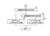
図8Cにおいて、LPF5032は、ステップS7にて、移動指令信号CSにおける低域周波数成分のみを通過させるフィルタリング処理(ベッセルフィルタ処理)を実行することにより、図9B及び図10Bに示すような速度制御情報を含む主移動指令信号MCSを生成する。図9Bは、主移動指令信号MCSにおける各時点のX軸方向の速度を示している。図10Bは、主移動指令信号MCSにおける各時点のY軸方向の速度を示している。主移動指令信号MCSは、加工ヘッド35(ノズル中心NC)の移動方向及び移動速度を制御するための移動指令信号である。
主移動指令信号MCSは、時点tbまでの期間、及び時点tfから時点tgまでの期間において、Y軸方向の移動速度を0とし、X軸方向の移動速度を加工条件CPに基づく所定の速度Vxaとして、加工ヘッド35(ノズル中心NC)をX軸方向に移動させる等速移動指令を含む。
主移動指令信号MCSは、図9Bに示すように、時点tbから時点tfまでの期間において、加工ヘッド35をX軸方向に対しては移動速度が加工条件CPに基づく所定の速度Vxaから、速度Vxaよりも遅い速度Vxbとなるように減速させる減速指令と、速度Vxbから速度Vxaとなるように加速させる加速指令とを含む。
主移動指令信号MCSは、図10Bに示すように、時点tbから時点tfまでの期間において、加工ヘッド35をY軸方向に対しては移動速度が0から加工条件CPに基づく所定の速度Vybとなるように加速させる加速指令と、速度Vybから0となるように減速させる減速指令とを含む。
X軸方向において、座標点Pbから座標点Pcまでの加工方向と座標点Pdから座標点Peまでの加工方向とは同じである。従って、図9Bに示すように、時点tbから時点tfまでの期間における速度プロファイルと時点tgから時点thまでの期間における速度プロファイルとは同じである。
Y軸方向において、座標点Pbから座標点Pcまでの加工方向と座標点Pdから座標点Peまでの加工方向とは互いに逆方向である。従って、図10Bに示すように、時点tbから時点tfまでの期間における速度プロファイルと時点tgから時点thまでの期間における速度プロファイルとは、正負が反転した関係を有する。
即ち、主移動指令信号MCSは、加工ヘッド35をX軸方向、Y軸方向、または、X軸とY軸との任意の合成方向に移動させ、かつ、座標点Pa~Peにおける各区間の加工ヘッド35の移動速度を制御するための移動指令信号である。
さらに、LPF5032は、主移動指令信号MCSを減算器5033及び移動機構制御部505へ出力する。従って、減算器5033には、遅延器5031から遅延移動指令信号DCSが入力され、LPF5032から主移動指令信号MCSが入力される。
ビーム復帰距離BRDの具体的な算出方法について説明する。図9Bに示すように、移動制御部501は、時点tbから時点tdまでの時間、加工速度、及び加工ヘッド35の減速度に基づいて、距離Saを算出する。移動制御部501は、距離Sa、加工速度、及び、加工ヘッド35の減速度及び加速度に基づいて、距離Saと距離Sbとが同じ(Sa=Sb)になる時点tfを求める。移動制御部501は、時点tdから時点tfまでの時間、加工速度、加工ヘッド35の減速度及び加速度に基づいて、ビーム復帰距離BRDを算出する。よって、移動制御部501は、ビーム復帰距離BRDを取得する。
図8Cにおいて、減算器5033は、ステップS8にて、遅延移動指令信号DCSから主移動指令信号MCSを減算することにより、図9C及び図10Cに示すような速度制御情報を含む副移動指令信号SCSを生成する。図9Cは、副移動指令信号SCSにおける各時点のX軸方向の速度を示している。図10Cは、副移動指令信号SCSにおける各時点のY軸方向の速度を示している。なお、図9C及び図10Cでは、副移動指令信号SCSにおける各時点のX軸方向及びY軸方向の速度を、ノズル中心NCに対するビーム中心BCの相対速度として示している。
副移動指令信号SCSは、ビームスポットBS(ビーム中心BC)の移動方向及び移動速度を制御するための移動指令信号であり、ノズル中心NC(加工ヘッド35)に対するビーム中心BC(ビームスポットBS)の変位方向及び変位速度を制御するための移動指令信号である。
図9C及び図10Cに示すように、副移動指令信号SCSは、時点tbまでの期間、及び時点tfから時点tgまでの期間において、ノズル中心NCに対するビーム中心BCの相対速度(変位速度)を0として、即ち、加工ヘッド35と同じ速度VxaでビームスポットBS(ビーム中心BC)をX軸方向に移動させる等速移動指令を含む。
副移動指令信号SCSは、時点tbにおいて、ビームスポットBSの相対速度をX軸方向に対しては速度0から速度Vxcに瞬時に切り替え、Y軸方向に対しては速度0から速度Vycに瞬時に切り替える速度切り替え指令を含む。速度VxcはX軸方向に対して負の速度であり、速度VycはY軸方向に対して正の速度である。
副移動指令信号SCSは、時点tbから時点tdまでの期間において、ビームスポットBSをX軸方向に対しては相対速度が速度Vxcから、速度Vxcよりも速い速度Vxdとなるように加速させる加速指令と、Y軸方向に対しては相対速度が速度Vycから、速度Vycよりも遅い速度Vydとなるように減速させる減速指令とを含む。速度VxdはX軸方向に対して負の速度であり、速度VydはY軸方向に対して正の速度である。
副移動指令信号SCSは、時点tdにおいて、ビームスポットBSの相対速度をX軸方向に対しては速度Vxdから速度Vxeに瞬時に切り替え、Y軸方向に対しては速度Vydから速度Vyeに瞬時に切り替える速度切り替え指令を含む。速度VxeはX軸方向に対して正の速度であり、速度VyeはY軸方向に対して負の速度である。
なお、ガルバノスキャナユニット32によるビームスポットBS(ビーム中心BC)の加速度(減速度)は、加工ヘッド35(ノズル中心NC)の加速度(減速度)と比較して桁違いに大きい。従って、ビームスポットBSが加速または減速する時間は、加工ヘッド35が加速または減速する時間と比較して無視できる程度に短い。
そこで、説明をわかりやすくするために、図9C及び図10Cでは、時点tb及びtdにおいて速度(相対速度)が瞬間的に切り替わるように示している。上記の理由と同様の理由により、移動指令信号CSに対する遅延移動指令信号DCSの遅延時間は無視できる程度に短いため、図9A及び図10Aでは、移動指令信号CS及び遅延移動指令信号DCSを同じ速度プロファイルで示している。
図9Cに示すように、副移動指令信号SCSは、時点tdから時点tfまでの期間において、ビームスポットBSをX軸方向に対しては相対速度が速度Vxeから速度Vxeよりも速い速度Vxfとなるように加速させる加速指令と、速度Vxfから0となるように減速させる減速指令とを含む。速度VxfはX軸方向に対して正の速度である。
X軸方向において、座標点Pbから座標点Pcまでの加工方向と座標点Pdから座標点Peまでの加工方向とは同じである。従って、図9Cに示すように、時点tbから時点tfまでの期間における速度プロファイルと時点tgから時点thまでの期間における速度プロファイルとは同じである。
図10Cに示すように、副移動指令信号SCSは、時点tdから時点tfまでの期間において、ビームスポットBSをY軸方向に対しては相対速度が速度Vyeから速度Vyeよりも遅い速度Vyfとなるように減速させる減速指令と、速度Vyfから0となるように加速させる加速指令とを含む。速度VyfはY軸方向に対して負の速度である。
Y軸方向において、座標点Pbから座標点Pcまでの加工方向と座標点Pdから座標点Peまでの加工方向とは互いに逆方向である。従って、図10Cに示すように、時点tbから時点tfまでの期間における速度プロファイルと時点tgから時点thまでの期間における速度プロファイルとは、正負が反転した関係を有する。
図9Cに示す距離Scは、座標点Pbから座標点Pcまでの区間においてビームスポットBSの変位量が変化した量であり、座標点PbにおけるビームスポットBSの変位量と座標点PcにおけるビームスポットBSの変位量との差分に相当する。言い換えれば、距離Scは、座標点Pbにおけるノズル中心NCからビーム中心BCまでの距離と、座標点Pcにおけるノズル中心NCからビーム中心BCまでの距離との差分の距離に相当する。
距離Sdは、座標点PcからビームスポットBSが所定の状態(例えば初期設定状態)に復帰する時点tfに対応する座標点までの区間においてビームスポットBSの変位量が変化した量である。図9Bに示す距離Saと、図10Bに示す距離Seと、図10Cに示す距離Sgは、図9Cに示す距離Scと等しい。図9Bに示す距離Sbと、図10Bに示す距離Sfと、図10Cに示す距離Shは、図9Cに示す距離Sdと等しい。さらに、減算器5033は、副移動指令信号SCSを変位制御部506へ出力する。
図11及び図12は、それぞれ、X軸方向及びY軸方向における各時点のノズル中心NCとビーム中心BCとの距離(ビーム中心BCの変位量)を示している。図11に示す符号DDxは、ノズル中心NCとビーム中心BCとのX軸方向における距離の最大変化量、即ち、ビーム中心BCの変位量のX軸方向における最大変化量を示している。図12に示す符号DDyは、ノズル中心NCとビーム中心BCとのY軸方向における距離の最大変化量、即ち、ビーム中心BCの変位量のY軸方向における最大変化量を示している。
図11及び図12に示す符号DDmaxは、図5に一点鎖線で示すビーム移動範囲(距離)を示している。即ち、距離DDmaxは、DDmax=Ra、または、DDmax=Ra-Laで示される関係を有する。
図6に示すように、X軸キャリッジ22とY軸キャリッジ23とにより構成される移動機構は、X軸キャリッジ22及びY軸キャリッジ23をそれぞれ駆動する駆動部220及び230を有する。図8Cにおいて、移動機構制御部505は、ステップS9にて、主移動指令信号MCSに基づいて駆動部220及び230を制御することにより、加工ヘッド35を移動させる。変位制御部506は、ステップS10にて、副移動指令信号SCSに基づいてガルバノスキャナユニット32の駆動部322及び324を駆動して、ビームスポットBSを変位させる。
図8Aに示すステップS5にて、レーザビームLBがノズル36の開口部36aの領域内で変位しない(NO)と判定された場合について説明する。レーザビームLBがノズル36の開口部36aの領域内で変位しない(NO)と判定された場合とは、具体的には図8Bに示すステップS52にて、座標点間の距離Dが開口部36aの領域内に収まらない(No)と判定された場合、または、ステップS55にて、座標点P間の距離Dがビーム復帰距離BRD以上ではない(No)と判定された場合である。
図8Aに示すステップS5にて、レーザビームLBがノズル36の開口部36aの領域内で変位しない(NO)と判定された場合、図8Dにおいて、LPF5032は、ステップS17にて、移動指令信号CSにおける低域周波数成分のみを通過させるフィルタリング処理(ベッセルフィルタ処理)を実行する。
LPF5032は、上記のフィルタリング処理により、図9B及び図10Bに示すような速度制御情報を含む主移動指令信号MCSを生成する。ステップS17はステップS7に相当する。レーザ加工機100は、ステップS19にて、ビーム中心BCをノズル中心NCと一致させた状態で、加工プログラムPP及び加工条件CPに基づいて加工ヘッド35を移動させ、板金Wを加工する。
図9A~図9C、図10A~図10C、及び図13A~図13Gを用いて、図7Aに示すように板金Wを切り欠き部NSを有して切断するときの加工ヘッド35とビームスポットBSとの位置関係について説明する。
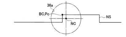
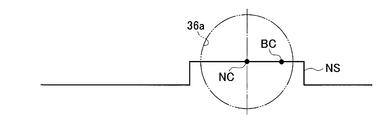
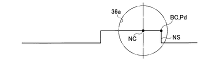
図13A~図13Gは、それぞれ、図9A~図9C、及び図10A~図10Cの時点ta~時点tgにおけるノズル中心NC(加工ヘッド35)とビーム中心BC(ビームスポットBS)との位置関係を示している。具体的には、図13Aは時点ta、図13Bは時点tb、図13Cは時点tc、図13Dは時点td、図13Eは時点te、図13Fは時点tf、図13Gは時点tgにおける板金Wの加工位置を示している。
図13Aに示すように、ビームスポットBS(レーザビームLB)は、ビーム中心BCがノズル中心NCに対して所定の変位量DAxだけX軸方向に変位する位置が初期設定位置となるように設定されている。時点taでは、加工ヘッド35は、ビームスポットBSが変位量DAxだけX軸方向に変位した状態で、速度VxaでX軸方向に移動している。
図13Bに示すように、時点tbでは、ビーム中心BCは座標点Pbに到達する。加工ヘッド35は、時点tbで移動方向をX軸方向からX軸とY軸との合成方向に変更し、かつ、X軸方向に対しては減速を開始し、Y軸方向に対しては加速を開始する。ビームスポットBSは、時点tbで移動方向を、X軸方向からY軸方向に変更する。ノズル中心NCに対するビーム中心BCの相対速度は、X軸方向に対しては速度0から速度Vxcに変更され、Y軸方向に対しては速度0から速度Vycに変更される。
ビームスポットBSは、時点tbで初期設定位置に対して変位を開始する。図11及び図12に示すように、ビーム中心BCとノズル中心NCとの距離は、時点tbでX軸方向に対しては短くなるように変更され、Y軸方向に対しては長くなるように変更される。即ち、時点tbでは、ビーム中心BCは、X軸方向に対してはノズル中心NCに接近する方向に変位を開始し、Y軸方向に対してはノズル中心NCから離隔する方向に変位を開始する。
図13Cに示すように、時点tcでは、加工ヘッド35は、移動方向を加工位置に応じてX軸とY軸との合成方向に変更し、かつ、X軸方向に対しては減速を継続し、Y軸方向に対しては加速を継続する。時点tcでは、ビームスポットBSは座標点Pbから座標点Pcに向かってY軸方向に移動中であり、かつ、加工位置に応じて変位量が変更される。
図13Dに示すように、時点tdでは、ビーム中心BCは座標点Pcに到達する。時点tdでは、加工ヘッド35は、移動方向を加工位置に応じてX軸とY軸との合成方向に変更し、かつ、X軸方向に対しては減速を継続し、Y軸方向に対しては加速を継続する。ビームスポットBSは、時点tcで移動方向を、Y軸方向からX軸方向に変更し、かつ、加工位置に応じて変位量が変更される。ノズル中心NCに対するビーム中心BCの相対速度は、X軸方向に対しては速度Vxdから速度Vxeに変更され、Y軸方向に対しては速度Vydから速度Vyeに変更される。
図11及び図12に示すように、時点tdでは、ビームスポットBSの変位量が初期設定位置に対して最大となる。即ち、ビームスポットBSの変位量は、時点tdで、ビーム中心BCのX軸方向及びY軸方向における最大変化量DDx及びDDyとなる。レーザビームLB(ビームスポットBS)は、距離DDmaxで示されるビーム移動範囲内において変位することができる。
図9B及び図10Bに示すように、時点tdから時点teまでの期間において、加工ヘッド35は、X軸方向に対しては減速後に加速を開始し、Y軸方向に対しては加速後に減速を開始する。図13Eに示すように、時点teでは、加工ヘッド35は、移動方向を加工位置に応じてX軸とY軸との合成方向に変更し、かつ、X軸方向に対しては加速を継続し、Y軸方向に対しては減速を継続する。時点teでは、ビームスポットBSは座標点Pcから座標点Pdに向かってX軸方向に移動中であり、かつ、加工位置に応じて変位量が変更される。
図13Fに示すように、時点tfでは、加工ヘッド35はX軸とY軸との合成方向に移動し、かつ、ビームスポットBS(レーザビームLB)はビーム中心BCが座標点Pcと座標点Pdとを結ぶ線上を移動し、かつ、初期設定位置に復帰する。ノズル中心NCに対するビーム中心BCの相対速度は、X軸方向及びY軸方向に対して0となる。時点tf以降では、加工ヘッド35及びビームスポットBSは、ビーム中心BCがノズル中心NCに対して変位量DAxだけX軸方向に変位した状態で、座標点Paと座標点Pbとを結ぶ線上を同じ軌跡で移動する。
従って、時点tbまでの期間は、加工ヘッド35及びビームスポットBSは、ビーム中心BCがノズル中心NCに対して変位量DAxだけX軸方向に変位した状態を維持して、座標点Paと座標点Pbとを結ぶ線上を同じ軌跡で移動する。時点tbまでの期間は座標点Pbまでの区間に相当する。
時点tbから時点tfまでの期間では、加工ヘッド35は、加工位置に応じてX軸とY軸との合成方向に移動することにより、切り欠き部NSの頂点(座標点Pc)よりも内側を通過する軌跡上を移動する。時点tbから時点tfまでの期間では、ビームスポットBSは、加工位置に応じて、初期設定位置に対して変位量を変更させながら変位し、座標点Paと座標点Pbとを結ぶ線上、座標点Pbと座標点Pcとを結ぶ線上、及び座標点Pcと座標点Pdとを結ぶ線上を順次移動する。
図13Gに示すように、時点tgでは、ビーム中心BCは座標点Pdに到達する。加工ヘッド35は、時点tgで移動方向をX軸方向からX軸とY軸との合成方向に変更し、かつ、X軸方向に対しては減速を開始し、Y軸方向に対しては加速を開始する。ビームスポットBSは、時点tbで移動方向を、X軸方向からY軸方向(具体的には-Y軸方向)に変更する。時点tb以降の加工方向と時点tg以降の加工方向とは互いに逆方向である。
従って、図10Bに示すように、時点tbから時点tfまでの期間における加工ヘッド35の速度プロファイルと、時点tgから時点thまでの期間における加工ヘッド35の速度プロファイルとは、互いに正負が反対の関係になる。同様に、図10Cに示すように、時点tbから時点tfまでの期間におけるビームスポットBSの速度プロファイルと、時点tgから時点thまでの期間におけるビームスポットBSの速度プロファイルとは、互いに正負が反対の関係になる。
レーザ加工機100及びそのレーザ加工方法では、板金Wを加工するときに、レーザビームLBがノズル36の開口部36aの領域内で変位するか否かを判定する。レーザ加工機100及びそのレーザ加工方法では、レーザビームLBがノズル36の開口部36aの領域内で変位すると判定された場合、座標点Pb及びPcにおける加工ヘッド35の移動方向を連続的に変更し、かつ、加工ヘッド35の移動速度の変化量を抑制し、かつ、加工速度を変更(減速)することなく、板金Wを精度良く加工することができる。
従って、レーザ加工機100及びレーザ加工方法によれば、切断進行方向を所定の角度以下の角部で曲げて板金Wを切断したり、切断進行方向を急激に変更して板金Wを曲線状に切断したりする場合でも、従来よりも板金Wを高速に切断することができ、加工時間を短くすることができる。
レーザ加工機100及びそのレーザ加工方法では、板金Wを加工するときに、座標点間の距離がビーム復帰距離BRD以上か否かを判定する。レーザ加工機100及びそのレーザ加工方法では、板金Wを加工中にビームスポットBSが初期設定位置に復帰できるか否かを判定する。そのため、レーザ加工機100は、ビームスポットBSが初期設定位置に復帰できる場合にはビームスポットBSを初期設定位置に対して変位させて板金Wを加工することができる。
レーザ加工機100は、レーザビームLBがノズル36の開口部36aの領域内で変位しない場合、または、ビームスポットBSが初期設定位置に復帰できない場合には、ビームスポットBSを初期設定位置に固定した状態で板金Wを加工する。即ち、レーザ加工機100及びそのレーザ加工方法によれば、板金Wの加工中におけるビームスポットBSの変位状態に応じて加工方法を変更することができる。
レーザ加工機100及びそのレーザ加工方法では、座標点間の距離がビーム復帰距離BRD以上でない場合、次の座標点間の距離がビーム復帰距離BRD以上であるか否かを判定してもよい。次の座標点間の距離がビーム復帰距離BRD以上である場合、レーザ加工機100は、ステップS5からステップS6へ処理を進めることができる。
本発明は以上説明した1またはそれ以上の実施形態に限定されるものではなく、本発明の要旨を逸脱しない範囲において種々変更可能である。
本願の開示は、2018年8月31日に出願された特願2018-162373号に記載の主題と関連しており、それらの全ての開示内容は引用によりここに援用される。
Claims (8)
- 先端部に円形の開口部を有し、前記開口部より板金を切断加工するためのレーザビームを射出するノズルが取り付けられている加工ヘッドと、
前記板金の面に対して前記加工ヘッドを相対的に移動させる移動機構と、
前記レーザビームが前記板金に照射されたときの照射位置におけるビームスポットの中心であるビーム中心を前記ノズルの中心であるノズル中心に対して変位させるビーム変位機構と、
前記板金を切断する加工方向及び加工速度を制御するための移動指令信号を生成し、かつ、前記板金の加工形状の座標情報を取得し、前記座標情報に基づいて前記レーザビームが前記開口部の領域内で変位するか否かを判定する移動制御部と、
前記レーザビームが前記開口部の領域内で変位すると判定された場合に、前記移動指令信号に基づいて、前記加工ヘッドの移動方向及び移動速度を制御するための主移動指令信号、及び、前記ビームスポットの移動方向及び移動速度を制御するための副移動指令信号を生成する移動指令分割部と、
前記主移動指令信号に基づいて、前記加工ヘッドを相対的に移動させるよう前記移動機構を制御する移動機構制御部と、
前記副移動指令信号に基づいて、前記ビーム中心が前記ノズル中心に対して変位するよう前記ビーム変位機構を制御する変位制御部と、
を備えるレーザ加工機。 - 前記移動制御部は、前記座標情報に含まれる座標点間の距離を算出し、前記距離が前記開口部の領域内に収まるか否かを判定する請求項1に記載のレーザ加工機。
- 前記移動制御部は、前記距離、前記加工速度、前記加工ヘッドの加速度または減速度、及び、前記座標情報に含まれる座標点間における前記ビームスポットの変位量が変化した差分に基づいて、前記板金を所定の加工速度で加工し、かつ、変位した前記ビームスポットが所定の位置に戻るまでに必要な距離であるビーム復帰距離を取得する請求項2に記載のレーザ加工機。
- 前記移動制御部は、前記座標情報に含まれる座標点間の距離と前記ビーム復帰距離とを比較し、前記距離が前記ビーム復帰距離以上である場合には、前記変位制御部は、前記副移動指令信号に基づいて、前記ビーム中心が前記ノズル中心に対して変位するよう前記ビーム変位機構を制御する請求項3に記載のレーザ加工機。
- 先端部に円形の開口部を有し、前記開口部より板金を切断加工するためのレーザビームを射出するノズルが取り付けられている加工ヘッドを備えるレーザ加工機が、
前記板金を切断する加工方向及び加工速度を制御するための移動指令信号を生成し、
前記板金の加工形状の座標情報を取得し、
前記座標情報に基づいて前記レーザビームが前記開口部の領域内で変位するか否かを判定し、
前記レーザビームが前記開口部の領域内で変位すると判定された場合に、前記移動指令信号に基づいて、前記加工ヘッドの移動方向及び移動速度を制御するための主移動指令信号、及び、前記レーザビームが前記板金に照射されたときの照射位置におけるビームスポットの移動方向及び移動速度を制御するための副移動指令信号を生成し、
前記主移動指令信号に基づいて前記加工ヘッドを相対的に移動させ、かつ、前記副移動指令信号に基づいて前記ビームスポットの中心であるビーム中心を前記ノズルの中心であるノズル中心に対して変位させて前記板金を切断する
レーザ加工方法。 - 前記レーザ加工機が、前記座標情報に含まれる座標点間の距離を算出し、前記距離が前記開口部の領域内に収まるか否かを判定する請求項5に記載のレーザ加工方法。
- 前記レーザ加工機が、前記距離、前記加工速度、前記加工ヘッドの加速度、及び、前記座標情報に含まれる座標点間における前記ビームスポットの変位量が変化した差分に基づいて、前記板金を所定の加工速度で加工し、かつ、変位した前記ビームスポットが所定の位置に戻るまでに必要な距離であるビーム復帰距離を取得する請求項6に記載のレーザ加工方法。
- 前記レーザ加工機が、前記座標情報に含まれる座標点間の距離と前記ビーム復帰距離とを比較し、前記距離が前記ビーム復帰距離以上である場合には、前記副移動指令信号に基づいて、前記ビーム中心が前記ノズル中心に対して変位させる請求項7に記載のレーザ加工方法。
Applications Claiming Priority (2)
| Application Number | Priority Date | Filing Date | Title |
|---|---|---|---|
| JP2018-162373 | 2018-08-31 | ||
| JP2018162373A JP6622876B1 (ja) | 2018-08-31 | 2018-08-31 | レーザ加工機及びレーザ加工方法 |
Publications (1)
| Publication Number | Publication Date |
|---|---|
| WO2020045081A1 true WO2020045081A1 (ja) | 2020-03-05 |
Family
ID=68917232
Family Applications (1)
| Application Number | Title | Priority Date | Filing Date |
|---|---|---|---|
| PCT/JP2019/031856 Ceased WO2020045081A1 (ja) | 2018-08-31 | 2019-08-13 | レーザ加工機及びレーザ加工方法 |
Country Status (2)
| Country | Link |
|---|---|
| JP (1) | JP6622876B1 (ja) |
| WO (1) | WO2020045081A1 (ja) |
Citations (2)
| Publication number | Priority date | Publication date | Assignee | Title |
|---|---|---|---|---|
| JP2014210277A (ja) * | 2013-04-18 | 2014-11-13 | 株式会社アマダミヤチ | レーザ切断方法、レーザ出射ユニット及びレーザ切断装置 |
| JP2018507109A (ja) * | 2015-04-06 | 2018-03-15 | 三菱電機株式会社 | 加工機械の動作を制御するための方法および制御システム、並びに加工機械 |
-
2018
- 2018-08-31 JP JP2018162373A patent/JP6622876B1/ja active Active
-
2019
- 2019-08-13 WO PCT/JP2019/031856 patent/WO2020045081A1/ja not_active Ceased
Patent Citations (2)
| Publication number | Priority date | Publication date | Assignee | Title |
|---|---|---|---|---|
| JP2014210277A (ja) * | 2013-04-18 | 2014-11-13 | 株式会社アマダミヤチ | レーザ切断方法、レーザ出射ユニット及びレーザ切断装置 |
| JP2018507109A (ja) * | 2015-04-06 | 2018-03-15 | 三菱電機株式会社 | 加工機械の動作を制御するための方法および制御システム、並びに加工機械 |
Also Published As
| Publication number | Publication date |
|---|---|
| JP6622876B1 (ja) | 2019-12-18 |
| JP2020032453A (ja) | 2020-03-05 |
Similar Documents
| Publication | Publication Date | Title |
|---|---|---|
| JP6638011B2 (ja) | レーザ加工機及びレーザ加工方法 | |
| JP7012820B2 (ja) | 切削加工機及び切削加工方法 | |
| JP6684872B2 (ja) | レーザ加工機及びレーザ加工方法 | |
| JP7579732B2 (ja) | レーザ加工機およびレーザ加工方法 | |
| EP3871825B1 (en) | Laser beam machine, laser beam machining method | |
| US20210354244A1 (en) | Laser machining apparatus and laser machining method | |
| JP6667735B1 (ja) | 切削加工機及び切削加工方法 | |
| CN112823075B (zh) | 激光加工机及激光加工方法 | |
| JP6622876B1 (ja) | レーザ加工機及びレーザ加工方法 | |
| EP3831527B1 (en) | Laser machining device and laser machining method | |
| WO2020021924A1 (ja) | レーザ加工機及びレーザ加工方法 | |
| WO2019176631A1 (ja) | 切削加工機及び切削加工方法 | |
| JP6986133B2 (ja) | 切削加工機及び切削加工方法 | |
| JP7805419B1 (ja) | レーザ加工機及びレーザ加工機の制御方法 | |
| JP7805416B1 (ja) | レーザ加工機及びレーザ加工機の制御方法 | |
| JP6820358B2 (ja) | レーザ加工機及びレーザ加工方法 | |
| JP7622211B2 (ja) | レーザ加工機及びレーザ加工方法 | |
| JP2016107288A (ja) | レーザー加工装置 | |
| JP2014111259A (ja) | レーザ加工方法、レーザ加工装置及びレーザ加工プログラム | |
| JP2018111126A (ja) | レーザー加工装置の加工方法 |
Legal Events
| Date | Code | Title | Description |
|---|---|---|---|
| 121 | Ep: the epo has been informed by wipo that ep was designated in this application |
Ref document number: 19853912 Country of ref document: EP Kind code of ref document: A1 |
|
| NENP | Non-entry into the national phase |
Ref country code: DE |
|
| 122 | Ep: pct application non-entry in european phase |
Ref document number: 19853912 Country of ref document: EP Kind code of ref document: A1 |