WO2020045070A1 - Dispositif d'étanchéité - Google Patents
Dispositif d'étanchéité Download PDFInfo
- Publication number
- WO2020045070A1 WO2020045070A1 PCT/JP2019/031758 JP2019031758W WO2020045070A1 WO 2020045070 A1 WO2020045070 A1 WO 2020045070A1 JP 2019031758 W JP2019031758 W JP 2019031758W WO 2020045070 A1 WO2020045070 A1 WO 2020045070A1
- Authority
- WO
- WIPO (PCT)
- Prior art keywords
- embankment
- ribs
- rib
- spiral
- lip edge
- Prior art date
Links
Images


Classifications
-
- F—MECHANICAL ENGINEERING; LIGHTING; HEATING; WEAPONS; BLASTING
- F16—ENGINEERING ELEMENTS AND UNITS; GENERAL MEASURES FOR PRODUCING AND MAINTAINING EFFECTIVE FUNCTIONING OF MACHINES OR INSTALLATIONS; THERMAL INSULATION IN GENERAL
- F16J—PISTONS; CYLINDERS; SEALINGS
- F16J15/00—Sealings
- F16J15/16—Sealings between relatively-moving surfaces
- F16J15/32—Sealings between relatively-moving surfaces with elastic sealings, e.g. O-rings
- F16J15/3204—Sealings between relatively-moving surfaces with elastic sealings, e.g. O-rings with at least one lip
-
- F—MECHANICAL ENGINEERING; LIGHTING; HEATING; WEAPONS; BLASTING
- F16—ENGINEERING ELEMENTS AND UNITS; GENERAL MEASURES FOR PRODUCING AND MAINTAINING EFFECTIVE FUNCTIONING OF MACHINES OR INSTALLATIONS; THERMAL INSULATION IN GENERAL
- F16J—PISTONS; CYLINDERS; SEALINGS
- F16J15/00—Sealings
- F16J15/16—Sealings between relatively-moving surfaces
- F16J15/32—Sealings between relatively-moving surfaces with elastic sealings, e.g. O-rings
- F16J15/3244—Sealings between relatively-moving surfaces with elastic sealings, e.g. O-rings with hydrodynamic pumping action
-
- F—MECHANICAL ENGINEERING; LIGHTING; HEATING; WEAPONS; BLASTING
- F16—ENGINEERING ELEMENTS AND UNITS; GENERAL MEASURES FOR PRODUCING AND MAINTAINING EFFECTIVE FUNCTIONING OF MACHINES OR INSTALLATIONS; THERMAL INSULATION IN GENERAL
- F16J—PISTONS; CYLINDERS; SEALINGS
- F16J15/00—Sealings
- F16J15/16—Sealings between relatively-moving surfaces
- F16J15/32—Sealings between relatively-moving surfaces with elastic sealings, e.g. O-rings
- F16J15/3204—Sealings between relatively-moving surfaces with elastic sealings, e.g. O-rings with at least one lip
- F16J15/3232—Sealings between relatively-moving surfaces with elastic sealings, e.g. O-rings with at least one lip having two or more lips
Definitions
- the present invention relates to a sealing device arranged between an inner member and an outer member that rotate relatively.
- a plurality of spiral ribs may be formed on the air-side surface of the seal lip of the sealing device arranged between the relatively rotating inner member and outer member.
- This type of sealing device is used to seal a liquid (e.g., a lubricant) disposed in an inner space of an outer member, and a helical rib is used to seal the liquid leaking to the atmosphere to the inner member and the outer member. With the relative rotation of, the effect of returning to the internal space (pumping effect) is brought about.
- the inner member is rotatable in both directions, for example on the axle of a motor vehicle, or if the sealing device is deployable on either the left or right axle of the motor vehicle, a pumping action is achieved in both rotations.
- spiral ribs having different inclination directions may be formed on the seal lip (for example, Patent Document 1).
- the present invention provides a sealing device that exerts a pumping action in both directions of rotation, which further reduces leakage of liquid from the internal space to the atmosphere.
- a sealing device is a sealing device that is disposed between an inner member and an outer member that relatively rotate, and seals a gap between the inner member and the outer member.
- the seal lip has a liquid-side inclined surface disposed on the inner space side, an air-side inclined surface disposed on the atmosphere side, and a peripheral portion at a boundary between the liquid-side inclined surface and the atmosphere-side inclined surface.
- a lip edge extending in the direction, wherein the liquid-side inclined surface is inclined away from the inner member as being away from the lip edge, and the air-side inclined surface is separated from the inner member as being away from the lip edge.
- a plurality of first spiral ribs that are inclined and extend from the lip edge to the atmosphere-side inclined surface and contact the outer peripheral surface of the inner member, and extend from the lip edge;
- a plurality of second helical ribs are formed to contact the outer peripheral surface, and the plurality of first helical ribs extend helically at an angle to the lip edge, and the plurality of second helical ribs Is before
- the first spiral rib inclines in a direction opposite to the first spiral rib and extends spirally with respect to a lip edge.
- the air-side inclined surface is disposed away from the lip edge and does not contact the outer peripheral surface of the inner member.
- a plurality of first embankment ribs and a plurality of second embankment ribs that are arranged apart from the lip edge and do not contact the outer peripheral surface of the inner member are formed, and the plurality of first embankment ribs are Are respectively arranged so as to intersect with extensions of the plurality of first spiral ribs, and extend in a spiral shape inclining in a direction opposite to the first spiral ribs, and each of the plurality of second embankment ribs is The second spiral rib is disposed so as to intersect with an extension of the second spiral rib, and extends in a spiral shape in a direction opposite to the second spiral rib.
- the first spiral rib and the second spiral rib extending in different directions exert a pumping action in rotation in both directions. That is, when rotating in the first direction, the first spiral rib returns the liquid from the atmosphere to the internal space, and when rotating in the second direction, the second spiral rib returns the liquid from the atmosphere to the internal space.
- the second spiral rib may cause the liquid to leak from the internal space to the atmosphere side, and at the time of rotation in the second direction, the first spiral rib may cause the liquid to leak to the internal space. May leak to the atmosphere.
- the first embankment rib dams the liquid leaked to the atmosphere by the first spiral rib when rotating in the second direction.
- first embankment rib Since the first embankment rib does not contact the outer peripheral surface of the inner member, an airflow accompanying the rotation exists between the outer peripheral surface of the inner member and the first embankment rib during rotation in the second direction.
- the liquid leaked to the atmosphere side is moved by the airflow along the first embankment rib toward the lip edge, and further passed to the second spiral rib.
- the liquid passed from the first embankment rib is returned to the internal space by the second spiral rib.
- the second embankment rib dams the liquid leaked to the atmosphere by the second spiral rib during rotation in the first direction.
- FIG. 3 is a sectional view of a seal lip corresponding to line III-III in FIG. 2. It is a figure which shows the flow which the liquid leaked from the lip edge of the seal lip is returned. It is a development view of an inner skin of a seal lip of a sealing device concerning a 2nd embodiment of the present invention.
- FIG. 6 is a sectional view of a seal lip corresponding to line VI-VI in FIG. 5. It is a development view of an inner skin of a seal lip of a sealing device concerning a 3rd embodiment of the present invention.
- a sealing device 1 according to a first embodiment of the present invention is disposed between a housing (outer member) 2 and a rotating shaft (inner member) 4.
- the gap between the rotating shaft 4 is sealed.
- a shaft hole 2A is formed in the housing 2, and the rotating shaft 4 is disposed in the shaft hole 2A.
- a liquid, that is, an oil, which is a lubricant, is disposed in the internal space of the housing 2.
- the rotating shaft 4 has a columnar shape
- the shaft hole 2A has a circular cross section
- the sealing device 1 has an annular shape, but only the left half thereof is shown in FIG.
- the sealing device 1 has an outer cylindrical portion 10, a connecting portion 12, and an inner cylindrical portion 14.
- the outer cylindrical part 10 is a mounting part mounted on the housing 2.
- the outer cylindrical portion 10 is fitted (that is, press-fitted) into the shaft hole 2A by an interference fit method.
- the connecting portion 12 is arranged closer to the atmosphere than the outer cylindrical portion 10 and connects the outer cylindrical portion 10 and the inner cylindrical portion 14.
- the sealing device 1 has a composite structure having an elastic ring 16 and a rigid ring 18.
- the elastic ring 16 is formed of an elastic material, for example, an elastomer.
- the rigid ring 18 is formed of a rigid material, for example, metal, and reinforces the elastic ring 16.
- the rigid ring 18 has a substantially L-shaped cross section. A part of the rigid ring 18 is embedded in the elastic ring 16 and is in close contact with the elastic ring 16. Specifically, the rigid ring 18 is provided over the outer cylindrical portion 10 and the connecting portion 12.
- the inner cylindrical portion 14 is made of only an elastic material, and the inner cylindrical portion 14 is formed with a seal lip 20 and a dust lip 22.
- the seal lip 20 and the dust lip 22 are arranged inside the shaft hole 4 ⁇ / b> A of the housing 2 and slidably contact the outer peripheral surface of the rotating shaft 4.
- the seal lip 20 separates the internal space of the housing 2 from the atmosphere and seals the liquid in the internal space. That is, the seal lip 20 has a role of preventing outflow of the lubricant.
- the dust lip 22 is disposed closer to the atmosphere than the seal lip 20 and plays a role in preventing foreign substances (including water (including mud water or salt water) and dust) from flowing into the internal space from the atmosphere side.
- the dust lip 22 is an inclined annular plate, and extends obliquely from its base toward the atmosphere side and radially inward.
- the seal lip 20 is a projection formed on the inner peripheral surface of the inner cylindrical portion 14, and includes a liquid-side inclined surface 24 disposed on the inner space side, an atmospheric-side inclined surface 26 disposed on the atmospheric side, and a liquid-side inclined surface 26. It has a lip edge 28 extending in the circumferential direction at the boundary between the inclined surface 24 and the atmosphere-side inclined surface 26.
- the liquid-side inclined surface 24 has the shape of a frustoconical side surface, and is inclined away from the rotation axis 4 as the distance from the lip edge 28 increases.
- the atmosphere-side inclined surface 26 also has the shape of a frustoconical side surface, and is inclined away from the rotation axis 4 as the distance from the lip edge 28 increases.
- a garter spring 30 that compresses the seal lip 20 radially inward is wound around the outer peripheral surface of the inner cylindrical portion 14.
- the garter spring 30 is not indispensable.
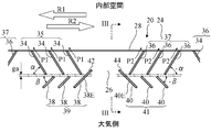
- FIG. 2 is a development view of the inner peripheral surface of the seal lip 20.
- the atmosphere-side inclined surface 26 has a plurality of first spiral ribs 34, a plurality of second spiral ribs 36, a plurality of first embankment ribs 38, and a plurality of second embankment ribs. 40 are formed.
- each group includes a plurality of groups 35 including a plurality of first spiral ribs 34 and each group includes a plurality of second spiral ribs.
- a plurality of groups 37 including 36 are provided on the atmosphere-side inclined surface 26, and the groups 35 and 37 are alternately arranged in the circumferential direction.
- a plurality of groups 39 each including a plurality of first embankment ribs 38 and a plurality of groups 41 each including a plurality of second embankment ribs 40 are provided on the air-side inclined surface 26, The groups 39 and 41 are alternately arranged in the circumferential direction.
- the first spiral rib 34 and the second spiral rib 36 extend from the lip edge 28 and extend in a helical manner at an angle to the lip edge 28.
- the first helical rib 34 and the second helical rib 36 are straight ridges.
- the second spiral rib 36 extends in a direction opposite to the direction in which the first spiral rib 34 inclines. That is, the first spiral rib 34 has an inclination angle ⁇ with respect to the lip edge 28, and the second spiral rib 36 has an inclination angle ⁇ with respect to the lip edge 28.
- FIG. 3 shows a state where the second spiral rib 36 contacts the outer peripheral surface of the rotating shaft 4.
- the second helical rib 36 has a uniform height over the longitudinal direction of the second helical rib 36, but a portion 36 ⁇ / b> A that contacts the outer peripheral surface of the rotating shaft 4 is elastically deformed.
- the first spiral rib 34 also has a uniform height in the longitudinal direction, but a portion that contacts the outer peripheral surface of the rotating shaft 4 is elastically deformed.
- the first spiral rib 34 and the second spiral rib 36 continuing from the lip edge 28 provide a pumping action of returning the liquid leaking from the lip edge 28 to the atmosphere to the internal space with the rotation of the rotating shaft 4.
- the rotating shaft 4 is rotatable in both directions, for example as in the case of a motor vehicle, or if the sealing device 1 can be deployed in either of the left and right axles of the motor vehicle, the pumping action in both directions of rotation.
- a first helical rib 34 and a second helical rib 36 having different inclination directions are formed on the seal lip 20. Specifically, when the rotating shaft 4 rotates in the first direction R1 in FIG.
- the first spiral rib 34 returns the liquid from the atmosphere side to the internal space as shown by the arrow P1.
- the second spiral rib 36 returns the liquid from the atmosphere side to the internal space. It is understood that such a pumping action is provided by minute irregularities on the atmosphere-side inclined surface 26, and the spiral ribs 34, 36 promote the pumping action depending on the extending direction.
- the second spiral rib 36 may cause the liquid to leak from the internal space to the atmosphere in the direction opposite to the arrow P2, and the rotating shaft 4
- the first spiral rib 34 may cause the liquid to leak from the internal space to the atmosphere in the direction opposite to the arrow P1. It is understood that such leakage is caused by minute deformation of the spiral ribs 34, 36 or a decrease in the tightening force of the spiral ribs 34, 36 with respect to the rotating shaft 4. Liquid leakage is more likely to occur as the rotation speed of the rotating shaft 4 is higher.
- the first embankment rib 38 and the second embankment rib 40 allow the liquid to flow from the internal space to the atmosphere. Leakage is further reduced.
- the first embankment rib 38 and the second embankment rib 40 are arranged apart from the lip edge 28 and extend spirally inclining with respect to the lip edge 28.
- the first embankment rib 38 and the second embankment rib 40 are linear ridges.
- the second embankment rib 40 extends obliquely in a direction opposite to the inclination direction of the first embankment rib 38. That is, the first embankment rib 38 has an inclination angle ⁇ with respect to the lip edge 28, and the second embankment rib 40 has an inclination angle ⁇ with respect to the lip edge 28.
- the group 39 of the first embankment ribs 38 overlaps the group 35 of the first spiral ribs 34 in the axial direction of the rotating shaft 4, and the group 41 of the second embankment ribs 40 extends in the axial direction of the rotating shaft 4.
- the second spiral rib 36 overlaps the group 37.
- the plurality of first embankment ribs 38 are arranged so as to intersect with the extensions of the plurality of first spiral ribs 34, and extend in a spiral shape in a direction opposite to the first spiral ribs 34.
- the plurality of second embankment ribs 40 are arranged so as to intersect with the extension lines of the plurality of second spiral ribs 36, and extend in a spiral shape in a direction opposite to the second spiral ribs 36.
- FIG. 3 shows a state in which the second embankment rib 40 is not in contact with the outer peripheral surface of the rotating shaft 4.
- a surface 40 ⁇ / b> A of the second embankment rib 40 facing the rotating shaft 4 is separated from the outer peripheral surface of the rotating shaft 4 and extends parallel to the outer peripheral surface.
- a gap G exists between the surface 40A and the rotation shaft 4.
- the surface of the first embankment rib 38 facing the rotating shaft 4 is also separated from the outer peripheral surface of the rotating shaft 4 and extends parallel to the outer peripheral surface.
- the first embankment rib 38 closest to the plurality of second embankment ribs 40 is referred to as a first end embankment rib 38E.
- the end 42 on the lip edge 28 side of the first end embankment rib 38E is closer to the lip edge 28 than the ends on the air side of the plurality of first spiral ribs 34, and The air-side end of the one end embankment rib 38E is farther from the lip edge 28 than the air-side end of the plurality of first spiral ribs 34. That is, the first end embankment rib 38E partially overlaps the first spiral rib 34 in the circumferential direction.
- the second embankment rib 40 closest to the plurality of first embankment ribs 38 among the plurality of second embankment ribs 40 is referred to as a second end embankment rib 40E.
- the end 44 on the lip edge 28 side of the second end embankment rib 40E is closer to the lip edge 28 than the atmospheric end of the plurality of second spiral ribs 36, and the second end embankment rib 40E is provided. Is closer to the lip edge 28 than the air-side ends of the plurality of second spiral ribs 36. That is, the second end embankment rib 40E partially overlaps the second spiral rib 36 in the circumferential direction.
- the end on the lip edge 28 side and the end on the atmosphere side of the first embankment rib 38 other than the first end embankment rib 38E are the ends on the atmosphere side of the plurality of first spiral ribs 34. Portion is farther from the lip edge 28. There is a gap ga between the end on the lip edge 28 side of the first embankment rib 38 other than the first end embankment rib 38E and the end on the atmosphere side of the first spiral rib 34. That is, the entirety of the first embankment ribs 38 does not overlap with the first spiral ribs 34 in the circumferential direction, and is arranged farther from the lip edge 28 than the first spiral ribs 34.
- the end of the second embankment rib 40 other than the second end embankment rib 40E on the lip edge 28 side and the end on the atmosphere side are more lip than the ends of the plurality of second spiral ribs 36 on the atmosphere side. Far from edge 28. There is a gap ga between the end of the second embankment rib 40 other than the second end embankment rib 40E on the lip edge 28 side and the end of the second spiral rib 36 on the atmosphere side. That is, the entirety of the second embankment ribs 40 does not overlap with the second spiral ribs 36 in the circumferential direction, and is arranged farther from the lip edge 28 than the second spiral ribs 36.
- the second spiral rib 36 causes the liquid to leak from the internal space to the atmosphere in the direction opposite to the arrow P2.
- the arrow A indicates the flow of the liquid leaked from the internal space by the second spiral rib 36.
- the second embankment rib 40 intersecting the extension of the second spiral rib 36 dams the liquid leaked to the atmosphere by the second spiral rib 36 when the rotating shaft 4 rotates in the first direction R1. .
- the second embankment rib 40 does not contact the outer peripheral surface of the rotating shaft 4, when the rotating shaft 4 rotates in the first direction R1, the outer wall of the rotating shaft 4 and the second embankment rib 40 are in contact with each other. In the gap G between them (see FIG. 3), there is an airflow accompanying rotation. The airflow is guided from the atmosphere side toward the lip edge 28 by the second embankment rib 40 as shown by the arrow B. The liquid leaked to the atmosphere side is moved toward the lip edge 28 along the second embankment rib 40 by this air flow.
- the liquid is moved in the circumferential direction by the airflow directed as shown by the arrow C. And reaches the first spiral rib 34.
- the first spiral rib 34 returns the liquid from the atmosphere side to the internal space by the pumping action (see the arrow P1 in FIG. 2). Accordingly, as shown by the arrow D in FIG. 4, the liquid is returned to the internal space along the first spiral rib 34.
- the liquid can be moved to the first spiral rib 34 by using the airflow, and the internal space can be moved. It is possible to further reduce leakage of liquid from the air to the atmosphere. Leakage of the liquid from the internal space is more likely to occur as the rotation speed of the rotating shaft 4 is higher, but the airflow is higher as the rotation speed is higher, so that much of the leaked liquid can be returned to the internal space.
- the first embankment rib 38 Dams the liquid that the first spiral rib 34 has leaked to the atmosphere side. Since the first embankment rib 38 does not contact the outer peripheral surface of the rotating shaft 4, when the rotating shaft 4 rotates in the second direction R2, the first embankment rib 38 is located between the outer peripheral surface of the rotating shaft 4 and the first embankment rib 38. Has an airflow accompanying rotation. The liquid leaked to the atmosphere side is moved toward the lip edge along the first embankment rib 38 by this air flow, and is transferred to the second spiral rib 36.
- the liquid passed from the first bank rib 38 to the second spiral rib 36 is returned to the internal space by the second spiral rib 36.
- the liquid can be moved to the second spiral rib 36 using the airflow, and the air can be removed from the internal space to the atmosphere. It is possible to further reduce the leakage of liquid to the side.
- the first end embankment rib 38E and the second end embankment rib 40E are, like the other first embankment rib 38 and the other second embankment rib 40, provided with the first spiral rib 34 and the The second spiral rib 36 does not need to overlap. Also in this case, the liquid can be transferred between the groups 35 and 37 by the airflow (in the case of rotation in the first direction R1, the airflow indicated by the arrow C).
- the second end embankment rib 40E partially overlaps with the second spiral rib 36 in the circumferential direction, so that when the rotation shaft 4 rotates in the first direction R1, The second end rib 40E can receive a large amount of liquid leaked from the second spiral rib 36 to the atmosphere side and pass it to the adjacent first spiral rib 34. Also, since the first end embankment rib 38E partially overlaps the first spiral rib 34 in the circumferential direction, when the rotation shaft 4 rotates in the second direction R2, the first spiral rib 34E. The first end embankment rib 38E can receive a large amount of liquid leaked to the atmosphere side and pass it to the adjacent second spiral rib 36.
- first embankment ribs 38 are located farther from the lip edge 28 than the plurality of first spiral ribs 34.
- at least some of the second embankment ribs 40 are located further away from the lip edge 28 than the plurality of second spiral ribs 36. Since the first embankment rib 38 and the second embankment rib 40 are formed on the inclined surface 26 on the atmosphere side, the further away from the lip edge 28, the less the possibility of contact with the rotating shaft 4. Even if the seal lip 20 is worn, the first embankment rib 38 and the second embankment rib 40 are less likely to contact the rotating shaft 4. From another point of view, it is possible to increase the height H (see FIG. 3) of the first embankment rib 38 and the second embankment rib 40 with respect to the air-side inclined surface 26 to improve the efficiency of liquid movement by air flow. it can.
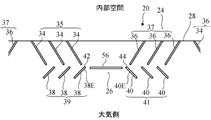
- FIG. 5 is a developed view of an inner peripheral surface of a seal lip 20 of a sealing device according to a second embodiment of the present invention.
- FIG. 6 is a cross-sectional view of the seal lip 20 corresponding to the line VI-VI in FIG.
- the same reference numerals are used to indicate the components already described, and these components will not be described in detail.
- each of the first spiral rib 34 and the second spiral rib 36 has a straight portion 50 and a bottom portion 52.
- the straight portion 50 is a portion referred to as a “parallel screw” in Patent Literature 1, extends linearly, and has side portions parallel to each other as shown in FIG.
- the bottom portion 52 is a portion called “bottom screw” in Patent Document 1 and has a bottom shape. That is, as shown in FIG. 5, the width of the ship bottom 52 gradually increases from one end along the longitudinal direction of the ship bottom 52, and gradually decreases from the center to the other end.
- the straight portion 50 and the bottom portion 52 are arranged in series, the straight portion 50 continues from the lip edge 28, and the bottom portion 52 is located on the atmosphere side.
- the straight portion 50 has a uniform height in the longitudinal direction of the straight portion 50, but the portion 36A that contacts the outer peripheral surface of the rotating shaft 4 is elastically deformed.
- the bottom portion 52 has an arc-shaped profile with a high center. In the initial state, the bottom 52 does not contact the outer peripheral surface of the rotating shaft 4, but when the seal lip 20 is worn, the bottom 52 contacts the outer peripheral surface of the rotating shaft 4. Therefore, even if the linear portion 50 is worn and the pumping action of the linear portion 50 is reduced, the ship bottom 52 compensates for the reduced pumping action.
- the height H of the embankment ribs 38, 40 is set such that the embankment ribs 38, 40 do not come into contact with the outer peripheral surface of the rotating shaft 4 even when the ship bottom 52 is considerably worn.
- each of the first embankment rib 38 and the second embankment rib 40 has a curved shape.
- FIG. 7 is a developed view of an inner peripheral surface of a seal lip 20 of a sealing device according to a third embodiment of the present invention.
- a plurality of circumferential dike ribs 56 are formed on the atmosphere-side inclined surface 26.
- the circumferential embankment rib 56 is arranged between the adjacent groups 39 and 41.
- the circumferential embankment rib 56 is disposed between the end 42 of the first end embankment rib 38E and the end 44 of the second end embankment rib 40E. Therefore, when the liquid is transferred between the groups 35 and 37 by the airflow (in the case of rotation in the first direction R1, the airflow indicated by the arrow C in FIG. 2), the liquid reaches the desired group more reliably. I do.
- the illustrated circumferential dike rib 56 is not connected to the first end dike rib 38E and the second end dike rib 40E, but the first end dike rib 38E and the second end dike rib 40E. May be connected.
- the circumferential dike rib 56 may be formed on the air-side inclined surface 26 of the seal lip 20 according to the second embodiment.
- the sealing device 1 is disposed between the housing (outer member) 2 and the rotating shaft (inner member) 4, but between the rotating outer member and the stationary inner member. It may be arranged.
- the shape and dimensions of the helical ribs and embankment ribs can be variously modified.
- Article 1 A sealing device that is disposed between an inner member and an outer member that rotate relatively, and seals a gap between the inner member and the outer member, An attachment portion attached to the outer member, A seal that is disposed inside the hole of the outer member, slidably contacts the outer peripheral surface of the inner member, and seals the liquid in the inner space by separating the inner space of the outer member from the atmosphere.
- the seal lip has a liquid-side inclined surface disposed on the inner space side, an air-side inclined surface disposed on the atmosphere side, and a peripheral portion at a boundary between the liquid-side inclined surface and the atmosphere-side inclined surface.
- the liquid-side inclined surface is inclined away from the inner member as being away from the lip edge
- the atmosphere-side inclined surface is inclined to be away from the inner member as being away from the lip edge
- a plurality of first spiral ribs extending from the lip edge and contacting the outer peripheral surface of the inner member; and the outer peripheral surface of the inner member extending from the lip edge and extending from the lip edge.
- a plurality of second helical ribs that are in contact with The plurality of first spiral ribs extend helically at an angle to the lip edge, and the plurality of second spiral ribs slope at an opposite direction to the lip edge from the first spiral rib.
- first embankment ribs that are arranged apart from the lip edge and do not contact the outer peripheral surface of the inner member, are arranged apart from the lip edge, and the A plurality of second embankment ribs that do not contact the outer peripheral surface are formed,
- the plurality of first embankment ribs are each arranged to intersect with an extension of the plurality of first spiral ribs, and extend in a spiral shape in a direction opposite to the first spiral ribs, and extend in a spiral shape.
- the second embankment ribs are arranged so as to intersect with the extension lines of the plurality of second spiral ribs, respectively, and are inclined in a direction opposite to the second spiral ribs and extend spirally. Sealing device.
- a first end embankment rib that is the first embankment rib closest to the plurality of second embankment ribs, the end on the lip edge side of the plurality of first embankment ribs, An air-side end of the first end embankment rib is closer to the lip edge than an air-side end of one of the spiral ribs is an air-side end of the plurality of first spiral ribs. Also far from the lip edge, Of the plurality of second embankment ribs, a lip edge side end of a second end embankment rib that is a second embankment rib closest to the plurality of first embankment ribs is the plurality of second embankment ribs.
- the second spiral rib is closer to the lip edge than the air-side end of the second spiral rib, and the air-side end of the second end embankment rib is closer to the air-side end of the plurality of second spiral ribs.
- the first end embankment rib partially overlaps with the first spiral rib in the circumferential direction, so that when rotating in the second direction, the first spiral rib leaks to the atmosphere side. It is possible for the first end embankment rib to receive as much liquid as possible and pass it to the adjacent second spiral rib. Also, since the second end embankment rib partially overlaps with the second spiral rib in the circumferential direction, many of the second spiral ribs leaked to the atmosphere during rotation in the first direction. Liquid can be received by the second end embankment rib and passed to the adjacent first spiral rib.
- At least some of the plurality of first embankment ribs have a lip edge end and an atmosphere side end of at least some of the first embankment ribs have an atmosphere end of the plurality of first spiral ribs.
- At least some of the second embankment ribs at the lip edge side and the atmosphere side end of the plurality of second embankment ribs are the atmosphere side ends of the plurality of second spiral ribs.
- At least some of the first embankment ribs are located further away from the lip edge than the plurality of first spiral ribs. Since the first embankment rib is formed on the inclined surface on the atmosphere side, the further away from the lip edge, the less the possibility of contact with the inner member. Even if the seal lip is worn, the first embankment rib is less likely to contact the inner member. From another viewpoint, it is possible to increase the height of the first embankment rib with respect to the inclined surface on the atmosphere side, and to improve the efficiency of liquid movement by the air flow. Also, at least some of the second embankment ribs are located further away from the lip edge than the plurality of second spiral ribs.
- the second embankment rib is formed on the inclined surface on the atmosphere side, the further away from the lip edge, the less the possibility of contact with the inner member. Even if the seal lip is worn, the second embankment rib is less likely to contact the inner member. From another viewpoint, it is possible to increase the height of the second embankment rib with respect to the inclined surface on the atmosphere side, and to improve the efficiency of moving the liquid by the air flow.
Landscapes
- Engineering & Computer Science (AREA)
- General Engineering & Computer Science (AREA)
- Mechanical Engineering (AREA)
- Physics & Mathematics (AREA)
- Fluid Mechanics (AREA)
- Sealing With Elastic Sealing Lips (AREA)
- Sealing Devices (AREA)
Abstract
Priority Applications (5)
| Application Number | Priority Date | Filing Date | Title |
|---|---|---|---|
| EP19855509.6A EP3845781A4 (fr) | 2018-08-28 | 2019-08-09 | Dispositif d'étanchéité |
| JP2020539315A JP6961094B2 (ja) | 2018-08-28 | 2019-08-09 | 密封装置 |
| US17/042,334 US20210010599A1 (en) | 2018-08-28 | 2019-08-09 | Sealing device |
| CN201980032094.1A CN112119245A (zh) | 2018-08-28 | 2019-08-09 | 密封装置 |
| KR1020207029342A KR20200127253A (ko) | 2018-08-28 | 2019-08-09 | 밀봉 장치 |
Applications Claiming Priority (2)
| Application Number | Priority Date | Filing Date | Title |
|---|---|---|---|
| JP2018159411 | 2018-08-28 | ||
| JP2018-159411 | 2018-08-28 |
Publications (1)
| Publication Number | Publication Date |
|---|---|
| WO2020045070A1 true WO2020045070A1 (fr) | 2020-03-05 |
Family
ID=69644245
Family Applications (1)
| Application Number | Title | Priority Date | Filing Date |
|---|---|---|---|
| PCT/JP2019/031758 WO2020045070A1 (fr) | 2018-08-28 | 2019-08-09 | Dispositif d'étanchéité |
Country Status (6)
| Country | Link |
|---|---|
| US (1) | US20210010599A1 (fr) |
| EP (1) | EP3845781A4 (fr) |
| JP (1) | JP6961094B2 (fr) |
| KR (1) | KR20200127253A (fr) |
| CN (1) | CN112119245A (fr) |
| WO (1) | WO2020045070A1 (fr) |
Cited By (2)
| Publication number | Priority date | Publication date | Assignee | Title |
|---|---|---|---|---|
| WO2022059360A1 (fr) * | 2020-09-15 | 2022-03-24 | Nok株式会社 | Dispositif d'étanchéité |
| EP3971452A4 (fr) * | 2019-05-16 | 2023-01-04 | NOK Corporation | Dispositif d'étanchéité |
Families Citing this family (1)
| Publication number | Priority date | Publication date | Assignee | Title |
|---|---|---|---|---|
| KR102618081B1 (ko) * | 2022-02-21 | 2024-01-09 | 아라정밀 주식회사 | 양방향 회전축용 오일 씰 |
Citations (6)
| Publication number | Priority date | Publication date | Assignee | Title |
|---|---|---|---|---|
| US5711534A (en) * | 1994-12-06 | 1998-01-27 | Dichtungstechnik G. Bruss Gmbh & Co. Kg | Annular shaft seal having an elastic sealing lip |
| JP2000179700A (ja) * | 1998-12-17 | 2000-06-27 | Nok Corp | 密封装置 |
| US20070069479A1 (en) * | 2005-09-27 | 2007-03-29 | Nak Sealing Technologies Corporation | Sealing device |
| JP4702517B2 (ja) | 2004-03-31 | 2011-06-15 | Nok株式会社 | オイルシール |
| WO2015053170A1 (fr) * | 2013-10-10 | 2015-04-16 | Nok株式会社 | Dispositif de scellement hermétique |
| JP2016196928A (ja) * | 2015-04-03 | 2016-11-24 | Nok株式会社 | 密封装置 |
Family Cites Families (7)
| Publication number | Priority date | Publication date | Assignee | Title |
|---|---|---|---|---|
| JPS5540318A (en) * | 1978-09-11 | 1980-03-21 | Yoshio Arai | Pattern of seal lip for rotation in both directions |
| US7775528B2 (en) * | 2006-02-13 | 2010-08-17 | Freudenberg-Nok General Partnership | Bi-directional pattern for dynamic seals |
| CN103906953B (zh) * | 2012-02-15 | 2017-04-05 | 伊格尔工业股份有限公司 | 轴封装置 |
| JP5637172B2 (ja) * | 2012-04-27 | 2014-12-10 | Nok株式会社 | 密封装置 |
| US10352450B2 (en) * | 2014-06-10 | 2019-07-16 | Nok Corporation | Sealing device |
| JP6442203B2 (ja) * | 2014-09-16 | 2018-12-19 | Nok株式会社 | 密封装置 |
| CN107429846B (zh) * | 2015-03-31 | 2018-09-25 | Nok株式会社 | 密封装置 |
-
2019
- 2019-08-09 WO PCT/JP2019/031758 patent/WO2020045070A1/fr unknown
- 2019-08-09 KR KR1020207029342A patent/KR20200127253A/ko not_active Application Discontinuation
- 2019-08-09 JP JP2020539315A patent/JP6961094B2/ja active Active
- 2019-08-09 CN CN201980032094.1A patent/CN112119245A/zh active Pending
- 2019-08-09 US US17/042,334 patent/US20210010599A1/en not_active Abandoned
- 2019-08-09 EP EP19855509.6A patent/EP3845781A4/fr not_active Withdrawn
Patent Citations (6)
| Publication number | Priority date | Publication date | Assignee | Title |
|---|---|---|---|---|
| US5711534A (en) * | 1994-12-06 | 1998-01-27 | Dichtungstechnik G. Bruss Gmbh & Co. Kg | Annular shaft seal having an elastic sealing lip |
| JP2000179700A (ja) * | 1998-12-17 | 2000-06-27 | Nok Corp | 密封装置 |
| JP4702517B2 (ja) | 2004-03-31 | 2011-06-15 | Nok株式会社 | オイルシール |
| US20070069479A1 (en) * | 2005-09-27 | 2007-03-29 | Nak Sealing Technologies Corporation | Sealing device |
| WO2015053170A1 (fr) * | 2013-10-10 | 2015-04-16 | Nok株式会社 | Dispositif de scellement hermétique |
| JP2016196928A (ja) * | 2015-04-03 | 2016-11-24 | Nok株式会社 | 密封装置 |
Non-Patent Citations (1)
| Title |
|---|
| See also references of EP3845781A4 |
Cited By (3)
| Publication number | Priority date | Publication date | Assignee | Title |
|---|---|---|---|---|
| EP3971452A4 (fr) * | 2019-05-16 | 2023-01-04 | NOK Corporation | Dispositif d'étanchéité |
| US11773980B2 (en) | 2019-05-16 | 2023-10-03 | Nok Corporation | Sealing device |
| WO2022059360A1 (fr) * | 2020-09-15 | 2022-03-24 | Nok株式会社 | Dispositif d'étanchéité |
Also Published As
| Publication number | Publication date |
|---|---|
| KR20200127253A (ko) | 2020-11-10 |
| CN112119245A (zh) | 2020-12-22 |
| US20210010599A1 (en) | 2021-01-14 |
| EP3845781A1 (fr) | 2021-07-07 |
| JP6961094B2 (ja) | 2021-11-05 |
| JPWO2020045070A1 (ja) | 2021-03-18 |
| EP3845781A4 (fr) | 2021-10-27 |
Similar Documents
| Publication | Publication Date | Title |
|---|---|---|
| JP6445085B2 (ja) | 密封装置 | |
| WO2020045070A1 (fr) | Dispositif d'étanchéité | |
| WO2009130933A1 (fr) | Dispositif d’étanchéité | |
| JP6267475B2 (ja) | 密封装置 | |
| JP6177582B2 (ja) | 密封装置 | |
| JP2009074602A (ja) | オイルシール | |
| US10641395B2 (en) | Sealing apparatus | |
| US3801113A (en) | Rotary shaft seal | |
| JP6174288B1 (ja) | 密封装置 | |
| JP6442203B2 (ja) | 密封装置 | |
| WO2021182057A1 (fr) | Dispositif d'étanchéité et engrenage réducteur | |
| JP7161945B2 (ja) | 密封装置 | |
| JP5985360B2 (ja) | 密封装置 | |
| JP2020183776A (ja) | 密封装置 | |
| CN216381957U (zh) | 一种置于液体环境中的泵用机械密封结构 | |
| JP6545486B2 (ja) | 密封装置 | |
| JP6343202B2 (ja) | 密封装置 | |
| CN207539078U (zh) | 汽车水泵机械密封 | |
| WO2022059360A1 (fr) | Dispositif d'étanchéité | |
| JP6910263B2 (ja) | 密封構造 | |
| EP3872374A1 (fr) | Dispositif d'étanchéité et structure d'étanchéité | |
| JP2008020031A (ja) | オイルシール | |
| JP2020186768A (ja) | 密封装置 | |
| JP2020067106A (ja) | 密封装置 | |
| JP2020079634A (ja) | 密封装置 |
Legal Events
| Date | Code | Title | Description |
|---|---|---|---|
| 121 | Ep: the epo has been informed by wipo that ep was designated in this application |
Ref document number: 19855509 Country of ref document: EP Kind code of ref document: A1 |
|
| ENP | Entry into the national phase |
Ref document number: 2020539315 Country of ref document: JP Kind code of ref document: A |
|
| ENP | Entry into the national phase |
Ref document number: 20207029342 Country of ref document: KR Kind code of ref document: A |
|
| NENP | Non-entry into the national phase |
Ref country code: DE |
|
| ENP | Entry into the national phase |
Ref document number: 2019855509 Country of ref document: EP Effective date: 20210329 |