WO2020044740A1 - 路面状態推定方法及び路面状態推定装置並びにタイヤ - Google Patents
路面状態推定方法及び路面状態推定装置並びにタイヤ Download PDFInfo
- Publication number
- WO2020044740A1 WO2020044740A1 PCT/JP2019/024133 JP2019024133W WO2020044740A1 WO 2020044740 A1 WO2020044740 A1 WO 2020044740A1 JP 2019024133 W JP2019024133 W JP 2019024133W WO 2020044740 A1 WO2020044740 A1 WO 2020044740A1
- Authority
- WO
- WIPO (PCT)
- Prior art keywords
- vibration level
- road surface
- vibration
- tire
- signal
- Prior art date
- Legal status (The legal status is an assumption and is not a legal conclusion. Google has not performed a legal analysis and makes no representation as to the accuracy of the status listed.)
- Ceased
Links
Images




Classifications
-
- B—PERFORMING OPERATIONS; TRANSPORTING
- B60—VEHICLES IN GENERAL
- B60C—VEHICLE TYRES; TYRE INFLATION; TYRE CHANGING; CONNECTING VALVES TO INFLATABLE ELASTIC BODIES IN GENERAL; DEVICES OR ARRANGEMENTS RELATED TO TYRES
- B60C19/00—Tyre parts or constructions not otherwise provided for
-
- B—PERFORMING OPERATIONS; TRANSPORTING
- B60—VEHICLES IN GENERAL
- B60W—CONJOINT CONTROL OF VEHICLE SUB-UNITS OF DIFFERENT TYPE OR DIFFERENT FUNCTION; CONTROL SYSTEMS SPECIALLY ADAPTED FOR HYBRID VEHICLES; ROAD VEHICLE DRIVE CONTROL SYSTEMS FOR PURPOSES NOT RELATED TO THE CONTROL OF A PARTICULAR SUB-UNIT
- B60W40/00—Estimation or calculation of non-directly measurable driving parameters for road vehicle drive control systems not related to the control of a particular sub unit, e.g. by using mathematical models
- B60W40/02—Estimation or calculation of non-directly measurable driving parameters for road vehicle drive control systems not related to the control of a particular sub unit, e.g. by using mathematical models related to ambient conditions
- B60W40/06—Road conditions
-
- G—PHYSICS
- G01—MEASURING; TESTING
- G01H—MEASUREMENT OF MECHANICAL VIBRATIONS OR ULTRASONIC, SONIC OR INFRASONIC WAVES
- G01H17/00—Measuring mechanical vibrations or ultrasonic, sonic or infrasonic waves, not provided for in the other groups of this subclass
Definitions
- the present invention relates to a road surface condition estimation method and a road surface condition estimation device and a tire, and more particularly, to a method for estimating a road surface condition based on tire vibrations during running of a vehicle, a device for estimating a road surface condition, and a road surface condition.
- the present invention relates to a tire provided with a device for estimating.
- an acceleration sensor for detecting vibration and a signal processing means for processing the tire vibration detected by the acceleration sensor are provided in the tire as a module, and a high frequency in a region before kicking out of the tire vibration detected by the acceleration sensor is provided.
- the tire vibration detected by the acceleration sensor is related to the contact time of the tire, the level increases in proportion to the rotation speed of the tire. Therefore, an algorithm considering the speed is required, and the calculation becomes complicated and the amount of calculation increases.
- the amount of calculation is closely related to the size and power consumption of the sensor module. For example, when the amount of calculation is large, a high-speed CPU and a large memory capacity are required, the power consumption is increased, and as a result, the capacity of the battery is increased. This is not desirable because it increases the unbalance vibration.
- the present invention has been made in view of the above problems, and reduces a calculation amount for estimating a road surface state, and reduces a size and a weight of a module, a road surface state estimation method, a road surface state estimation device, and a tire.
- the purpose is to provide.
- a step of detecting vibration of a running tire and a method of extracting a partial vibration signal of a predetermined time width from two points at different times in a signal of the detected tire vibration Performing, extracting, for each extracted partial vibration signal, a component of a predetermined frequency band, calculating a vibration level for each extracted frequency band, a vibration level at one time, and The mode includes a step of calculating a vibration level ratio that is a ratio to a vibration level at a time, and a step of estimating a road surface state based on the calculated vibration level ratio.
- the size and weight of the module can be suppressed. As a result, power consumption can be reduced.
- the road surface condition is estimated based on the vibration level ratio that is the ratio between the vibration level at one time and the vibration level at the other time, the input to the tire due to the rotational speed of the tire or unevenness of the road surface. The influence can be offset and the road condition can be estimated.
- FIG. 3 is a hardware configuration diagram of a signal processing unit. It is a figure showing a waveform of tire vibration when a tire makes one rotation.
- 5 is a flowchart showing processing of a signal processing unit.
- 6 is a graph showing the speed dependency of the vibration level and a graph showing the speed dependency when the vibration level of the high frequency component is divided by the vibration level of the low frequency component.
- It is a figure which shows an example of the decision tree which estimates a road surface state.
- It is a schematic flowchart which shows the process of the estimation method of a road surface state. It is a block diagram showing other forms of a road surface condition estimation device.
- FIG. 1 is a block diagram showing a configuration example of a road surface state estimating apparatus 1 for implementing the road surface state estimating method according to the embodiment.
- the road surface condition estimating device 1 includes a tire-side device 2 and a vehicle-body-side device 4.
- the tire-side device 2 includes an acceleration sensor 11 that functions as a vibration detection unit that detects vibration of the tire 10, a signal processing unit 12 that processes a signal output from the acceleration sensor 11, and a processing result obtained by the signal processing unit 12
- a transmission unit 19 for transmitting to the side device 4 and a power supply (not shown) for supplying power to the acceleration sensor 11, the signal processing unit 12, the transmission unit 19, and the like are provided.
- the tire-side device 2 is configured as, for example, one module integrated with the acceleration sensor 11, the signal processing unit 12, the transmission unit 19, and the power supply.
- a battery such as a button battery, a power generator in a tire that generates power by rotation of the tire 10, or the like can be applied.
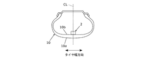
- FIG. 2 is a diagram showing a mounted state of the tire-side device 2.
- the tire-side device 2 includes an unillustrated inner liner 10 b on the back surface (tire air chamber side) of the tire tread 10 a so that the acceleration sensor 11 is disposed at the center CL in the tire width direction. It is provided by fixing means. More specifically, the detection direction of the acceleration of the acceleration sensor 11 is arranged so as to detect the vibration in the tire circumferential direction generated in the running tire 10. For example, a sensor capable of detecting vibration up to 20000 Hz is applied to the acceleration sensor 11.
- the acceleration sensor 11 only needs to be capable of detecting at least vibration in the tire circumferential direction, and may be capable of simultaneously detecting acceleration in a plurality of directions such as one axis, two axes, and three axes. From the viewpoint of power consumption, a uniaxial acceleration sensor 11 for detecting vibration in the tire circumferential direction is preferable.
- the detection direction of the tire vibration by the acceleration sensor 11 is not limited to the tire circumferential direction, but may be the tire radial direction or the tire width direction.
- the detection direction of the tire vibration by the acceleration sensor 11 is set to the tire radial direction, the influence of the mounting error of the acceleration sensor 11 with respect to the tire 10 is small, and the output of the tire vibration detected by the acceleration sensor 11 is large. There is the advantage that the ratio is high.
- the detected tire vibration is affected by the centrifugal acceleration, when the tire 10 rotates at a high speed, the output of the tire vibration becomes too large, and a process for canceling the influence of the rotation speed is required.
- FIG. 3 is a hardware configuration diagram of the signal processing unit 12.
- the signal processing unit 12 includes a CPU 12A as an arithmetic unit, a storage unit 12B such as a ROM and a RAM, and an input / output unit 12C.
- the storage unit 12B stores a program for processing a signal input from the acceleration sensor 11, and the like. Then, the CPU 12A functions as each unit described later by executing processing according to the program stored in the storage unit 12B.
- the input / output unit 12C is connected to the acceleration sensor 11 and functions as an input interface for inputting a tire vibration signal output from the acceleration sensor 11 and an output interface for outputting a calculation result by the CPU 12A to the transmission unit 19.
- the signal processing unit 12 is configured, for example, as a one-chip computer or the like in order to save space and reduce power consumption.
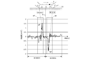
- FIG. 4 is a diagram showing an example of a waveform of tire vibration when the tire makes one revolution.
- FIG. 5 is a flowchart showing the processing of the signal processing means 12. As shown in FIGS. 1 and 5, the signal processing unit 12 includes a signal extraction unit 15, a filter processing unit 16, a vibration level calculation unit 17, and a vibration level ratio calculation unit 18. The signal processing means 12 executes a process based on the tire vibration detected each time the tire 10 makes one rotation, that is, each time the tire-side device 2 makes one rotation.
- the signal extracting unit 15 includes, for example, an area setting unit 15A and a sampling unit 15B, and detects a tire vibration at a different time from a tire vibration signal detected by the acceleration sensor 11 shown in FIG. Are extracted from a plurality of places, in this embodiment, two places.
- the region setting unit 15 ⁇ / b> A includes a positive / negative peak value included in the input tire vibration, a peak pf at a stepping point (at the time of stepping), and a peak pr at a kicking point (at the time of kicking).
- the midpoint of the time of the detected peak pf; pr is calculated as the contact center X
- the range of the time before the calculated contact center X is the front region Rf
- the range of the time after the calculated contact center X is the rear region.
- the sampling unit 15B sets a sampling region to be processed in each of the regions Rf; Rr set by the region setting unit 15A.
- the setting of the sampling region is performed by, for example, multiplying each of the front region Rf and the rear region Rr by a window function having a predetermined time width, and setting one at the front region Rf and one at the rear region Rr.
- a sampling area wf; wr is set.
- a signal of the tire vibration included in the set sampling area wf; wr is extracted as a partial vibration signal (a front extraction signal Sf, a rear extraction signal Sr).
- the extracted front extraction signal Sf and rear extraction signal Sr are output to the filtering means 16.
- the position where the window function is multiplied in the sampling unit 15B may be set as appropriate, such as a position offset at a predetermined time interval from the time of the grounding center X to the front region Rf and the rear region Rr, including the peak pf; Since the tire vibration near the peak pf; pr contains effective information indicating the road surface condition to be estimated, it is preferable to set the vicinity of the peak pf; pr or to include the peak pf; pr.
- the filter processing unit 16 executes a so-called filter process of extracting signals in a plurality of different bands from the front extraction signal Sf and the rear extraction signal Sr extracted by the signal extraction unit 15. For example, the filter processing unit 16 selects a predetermined frequency band from a range of 0 to 1 kHz and a range of higher than 1 kHz and 5 kHz from the front extraction signal Sf and the rear extraction signal Sr. By selecting a frequency band within each of the above ranges, a characteristic indicating a road surface condition can be suitably obtained.
- the filter processing unit 16 in the present embodiment includes a low frequency component extraction unit 20 that extracts a low frequency band (component) from the front extraction signal Sf and the rear extraction signal Sr, and a high frequency component extraction unit 22 that extracts a high frequency band (component). And Note that the filter processing unit 16 may be configured as a bandpass filter that extracts a signal from the above-described frequency band.
- a low frequency refers to a signal of 1 kHz or less
- a high frequency refers to a signal higher than 1 kHz.
- the low-frequency component extraction unit 20 is a so-called low-pass filter (LPF) that passes signals of 1 kHz or less of the front extraction signal Sf and the rear extraction signal Sr.
- LPF low-pass filter
- the low-frequency component extraction unit 20 may be referred to as an LPF 20.
- the high-frequency component extraction unit 22 is a so-called high-pass filter (HPF) that passes signals higher than 1 kHz of the front extraction signal Sf and the rear extraction signal Sr.
- the high-frequency component extraction unit 22 includes a plurality of high-pass filters (HPF) 22A to 22D that extract different high-frequency components in bands having different lower limit values from the front extraction signal Sf and the rear extraction signal Sr. Specifically, a first HPF 22A that extracts a high-frequency signal whose frequency is higher than 1 kHz, a second HPF 22B that extracts a high-frequency signal higher than 2 kHz, a third HPF 22C that extracts a signal higher than 3 kHz, and a signal that is higher than 4 kHz And a fourth HPF 22D that extracts
- the low frequency signal Lsf and the low frequency signal Lsr are extracted from the front extraction signal SF and the rear extraction signal Sr by the processing by the LPF 20 of the filter processing unit 16, and the high frequency signal Hsf1 and the high frequency signal Hsr1 are extracted by the processing by the first HPF 22A.
- the high-frequency signal Hsf2 and the high-frequency signal Hsr2 are extracted by the processing by the 2HPF 22B, the high-frequency signal Hsf3 and the high-frequency signal Hsr3 are extracted by the processing by the third HPF 22C, and the high-frequency signal Hsf4 and the high-frequency signal Hsr4 are extracted by the processing by the fourth HPF 22D.
- the vibration level calculation means 17 outputs the low frequency signal Lsf, the low frequency signal Lsr, the high frequency signal Hsf1, the high frequency signal Hsr1, the high frequency signal Hsf2, the high frequency signal Hsr2, the high frequency signal Hsf3, the high frequency signal Hsr3, and the high frequency signal extracted by the filter processing means 16.
- the vibration levels of the signal Hsf4 and the high-frequency signal Hsr4 are calculated.
- the vibration level calculating means 17 averages the values obtained by squaring and time-integrating each of the signals Lsf, Lsr, Hsf1 to Hsf1 to Hsr1 to Hsr4, and taking the square root. Calculate the vibration level. That is, the vibration level calculating means 17 calculates the RMS (root mean square) of each of the signals Lsf, Lsr, Hsf1 to Hsf1 to Hsr1 to 4, and calculates each of the signals Lsf, Lsr, Hsf1 to 4, and Hsr1 to Hsr4. Is calculated as the vibration level.
- the level PHsf3 and the high-frequency vibration level PHsf4 of the high-frequency signal Hsf4 are calculated, and the low-frequency vibration level PLsr of the low-frequency signal Lsr included in the rear extraction signal Sr, the high-frequency vibration level PHsr1 of the high-frequency signal Hsr1, and the high-frequency vibration level PHsr2 of the high-frequency signal Hsr2.
- the high-frequency vibration level PHsr3 of the high-frequency signal Hsr3 and the high-frequency vibration level PHsr4 of the high-frequency signal Hsr4
- the vibration level ratio calculating means 18 calculates the vibration level ratio of each of the signals Lsf, Lsr, Hsf1 to Hsf1 to Hsr1 to Hsr4 calculated by the vibration level calculating means 17.
- the vibration level ratio in the present embodiment refers to the high-frequency vibration levels PHsf1, PHsf2, PHsf3, PHsf4 and PHsf2 of the front extraction signal Sf based on the low-frequency vibration levels PLsf and PLsr obtained from the front extraction signal Sf and the rear extraction signal Sr. It is calculated by dividing the high frequency vibration levels PHsr1, PHsr2, PHsr3, and PHsr4 of the rear extraction signal Sr.
- the vibration level ratio is calculated as follows.
- the high-frequency vibration level PHsf1 is divided by the low-frequency vibration level PLsf to divide the vibration level ratio R1
- the high-frequency vibration level PHsf2 is divided by the low-frequency vibration level PLsf to divide the vibration level ratio R2
- the high-frequency vibration level PHsf3 is converted to the low-frequency vibration level PLsf.
- the vibration level ratio R3 is calculated by dividing the high frequency vibration level PHsf4 by the low frequency vibration level PLsf.
- the vibration level ratio R5 is obtained by dividing the high frequency vibration level PHsf1 by the low frequency vibration level PLsr
- the vibration level ratio R6 is obtained by dividing the high frequency vibration level PHsf2 by the low frequency vibration level PLsr
- the high frequency vibration level PHsf3 is obtained by dividing the high frequency vibration level PLsr.
- the vibration level ratio R7 is calculated by dividing the high frequency vibration level PHsf4 by the low frequency vibration level PLsr.
- the vibration level ratio R9 is obtained by dividing the high frequency vibration level PHsr1 by the low frequency vibration level PLsf
- the vibration level ratio R10 is obtained by dividing the high frequency vibration level PHsr2 by the low frequency vibration level PLsf
- the high frequency vibration level PHsr3 is obtained by dividing the high frequency vibration level PLsf.
- the vibration level ratio R11 is calculated by dividing the high frequency vibration level PHsr4 by the low frequency vibration level PLsf.
- the vibration level ratio R13 is obtained by dividing the high frequency vibration level PHsr1 by the low frequency vibration level PLsr
- the vibration level ratio R14 is obtained by dividing the high frequency vibration level PHsr2 by the low frequency vibration level PLsr
- the high frequency vibration level PHsr3 is obtained by dividing the high frequency vibration level PLsr.
- the high frequency vibration level PHsr4 divided by the low frequency vibration level PLsr to calculate the vibration level ratio R16. Then, the calculated vibration level ratios R1 to R16 are output to the transmission unit 19, and are output to the vehicle body-side device 4 via the transmission unit 19.
- the vibration level ratio is determined by the low-frequency vibration levels PLsf and PLsr obtained from the front extraction signal Sf and the rear extraction signal Sr, and the high-frequency vibration levels PHsf1, PHsf2, and PHsf3 of the front extraction signal Sf. , PHsf4, and the high-frequency vibration levels PHsr1, PHsr2, PHsr3, and PHsr4 of the rear extraction signal Sr, but the present invention is not limited to this.
- a value obtained by dividing the vibration levels PHsf1, PHsf2, PHsf3, and PHsf4 of the high-frequency components obtained from the front extraction signal Sf by the vibration levels PHsr1, PHsr2, PHsr3, and PHsr4 of the high-frequency components obtained from the rear extraction signal Sr is described above.
- the vibration level ratio obtained by dividing the vibration level PLsf of the low frequency component obtained from the front extraction signal Sf by the vibration level PLsr of the low frequency component obtained from the rear extraction signal Sr. May be added.
- the vibration level calculated as described above and the vibration level ratio calculated based on the vibration level can be said to be a feature amount indicating the road surface state.
- the vibration level calculated by dividing the vibration level of the high frequency component obtained from the front extraction signal Sf by the vibration level of the high frequency component obtained from the rear extraction signal Sr are also influential features indicating the road surface condition. Quantity.
- FIG. 6A is a graph showing the speed dependency of the vibration level
- FIG. 6B is a graph showing the speed dependency when the vibration level of the high frequency component is divided by the vibration level of the low frequency component. is there.
- the vibration level increases as the speed increases for both the low frequency and the high frequency.
- the vibration level of the high frequency component greatly increases as the speed increases.
- dividing the vibration level of the high frequency component by the vibration level of the low frequency component was almost flat. Therefore, by calculating the vibration level ratios R1 to R16 as described above, the influence of the centrifugal force when the tire 10 rotates at high speed and the influence of the road surface unevenness can be canceled.
- the vehicle body-side device 4 includes a receiving unit 31 that receives the vibration level ratios R1 to R16 transmitted from the tire-side device 2, and a state of a road surface on which the vehicle is traveling based on the received vibration level ratios R1 to R16.
- the receiving means 31 is configured to be able to receive the vibration level ratios R1 to R16 transmitted from the transmitting means 19 of the tire-side device 2.
- the road surface state estimating means 33 includes a CPU as a calculating means, a storage means such as a ROM and a RAM, and an input / output means.
- the storage means stores a program for estimating a road surface condition and the like. Then, the CPU executes the program stored in the storage means to estimate the road surface state based on the vibration level ratios R1 to R16 input from the tire-side device 2.
- the input / output unit is connected to the receiving unit 31 and functions as an input interface for inputting signals of the vibration level ratios R1 to R16 transmitted from the tire-side device 2 and an output interface for outputting a calculation result by the CPU.
- the road surface state estimating unit 33 determines the road surface state based on so-called machine learning.
- ⁇ 1, ⁇ 2, ⁇ 3 are explanatory variables for determining the road surface condition.
- each of the explanatory variables ⁇ 1, ⁇ 2, ⁇ 3 is a comparison value (a set value based on the vibration level ratio).
- Threshold values ⁇ 1 (corresponding to ⁇ 1), ⁇ 2 (corresponding to ⁇ 2), and ⁇ 3 (corresponding to ⁇ 3) are respectively set.
- the explanatory variables in the decision tree are a data set of vibration level ratios (hereinafter, referred to as DRY data) on a DRY road surface and a vibration on a WET road surface when the vehicle on which the tire-side device 2 is mounted travels on a DRY road surface and a WET road surface.
- a data set of level ratios (hereinafter referred to as WET data) is acquired, and comparison values (thresholds) ⁇ 1, ⁇ 2, ⁇ 3 set for the explanatory variables ⁇ 1, ⁇ 2, ⁇ 3 in the decision tree based on the DRY data and WET data
- the determination order and the like for estimating the road surface state are set by the explanatory variables ⁇ 1, ⁇ 2, and ⁇ 3.
- the processing by the signal processing means 12 extracts the characteristic amount indicating the road surface state from the tire vibration.
- the processing by the road surface state estimating unit 33 selects a combination of a frequency band when the vibration level ratio is calculated by the signal processing unit 12 and a waveform extracted from tire vibration by machine learning.
- the determination of the road surface state is described as DRY and WET.
- the determination of the road surface state by the road surface state estimating means 33 is not limited to this. Other road surfaces can also be determined.
- the amount of calculation can be reduced by processing only the feature amounts (here, the explanatory variables ⁇ 1, ⁇ 2, and ⁇ 3) selected by machine learning.
- FIG. 8 is a schematic flowchart showing the processing of the road surface state estimation method according to the present embodiment.
- tire acceleration corresponding to the road surface condition is detected by the acceleration sensor 11, and the detected tire vibration is output to the signal processing means 12.
- the signal extracting unit 15 executes sampling for extracting partial vibrations having a predetermined time width from two places at different times of the inputted tire vibration (S101).
- the filter processing unit 16 executes a filter process of extracting a component in a predetermined frequency band from the partial vibration extracted in S101 (S102).
- the vibration level calculating means 17 executes an averaging process for calculating the vibration level for each frequency band extracted in S102 (S103).
- the vibration level ratio calculating means 18 calculates a vibration level ratio which is a ratio between the vibration level at one time calculated in S103 and the calculated vibration level at the other time (S104).
- the road surface condition is estimated by the road surface condition estimation means 33 based on the vibration level ratio calculated in S104 (S105).
- a display device provided in the vehicle, for example, a display device such as a smartphone or a car navigation device owned by the driver, output to a control device that controls the vehicle, or road management that manages the road. It may be configured appropriately such as outputting to a user via a smartphone.
- the road surface condition estimation method by processing the tire vibration detected by the acceleration sensor 11, the road surface condition when the tire vibration is detected without being affected by the speed.
- the vibration level ratio can be acquired as the characteristic amount representing Further, the obtained vibration level ratio makes it possible to collectively handle those having different speeds, so that speed information is not required. Further, the calculation of the vibration level ratio is only a simple division, and the amount of calculation during the operation of the tire-side device 2 can be reduced. As a result, a large CPU 12A and a large-capacity storage unit 12B become unnecessary, and it is possible to suppress an increase in the size and weight of the module. As a result, power can be saved and the operating time can be extended.
- the road surface state is estimated based on the tire vibration detected each time the tire 10 makes one rotation, but the present invention is not limited to this. That is, in the above-described embodiment, the road surface state is determined based on the acceleration signal acquired during one rotation of the in-tire sensor. For example, the road surface state is acquired during two revolutions of the in-tire sensor. The road surface condition may be determined based on a tire vibration signal.
- the setting of one rotation of the tire is set as before or after contact with the ground, but is not limited to this. That is, in the tire vibration division processing by the area setting unit 15A, the processing is divided into two areas. However, the present invention is not limited to this. The processing may be performed by dividing the processing into two or more plural areas. In the case where the road surface is divided into a plurality of regions as described above, by performing the processing by the signal processing unit 12 for each region, a large number of samplings of the feature amount indicating the road surface state can be obtained. Can be improved.
- the signal extracting unit 15 has been described as extracting the sampling area by executing the windowing process of a predetermined time width with reference to two peak positions of the tire vibration appearing near the tire contact surface.
- the present invention is not limited to this, and the front area Rf and the rear area Rr set by the area setting unit 15A may be used as the sampling area.
- the signal extracting means 15 has been described as setting one sampling area by the sampling unit 15B from each of the front area Rf and the rear area Rr set by the area setting unit 15A. May set two sampling regions from the front region Rf without setting the sampling region, and set two sampling regions from the rear region Rr without setting the sampling region in the front region Rf. May be.
- the high-frequency component extraction unit 22 extracts the high-frequency component signal from the tire vibration signal in four steps, the number is for convenience of explanation and is not limited to this.
- a signal of a higher frequency may be extracted, for example, by providing a fifth high-pass filter for extracting a signal higher than 5 kHz, and may be set according to the processing capability of the hardware constituting the signal processing unit 12. Just do it.
- the low frequency band and the high frequency band are set with 1 kHz as a boundary, the present invention is not limited to this, and the bands may be set according to the structure and characteristics of the tire 10.
- the tire-side device 2 and the vehicle-body-side device 4 have been described.
- the signal processing unit 12 that processes the output signal and the road surface state estimating unit 33 may be integrally configured as the tire device 2. That is, as described above, since the amount of calculation can be reduced by determining the road surface state by machine learning, the hardware configuration that functions as the road surface state estimating unit 33 can be reduced, and the hardware configuration included in the tire-side device 2 can be reduced. Instead, it can be provided in the tire 10.
- the road surface state estimated by the road surface state estimating unit 33 is transmitted to the vehicle body-side device 4 by the transmitting unit 19, received by the receiving unit 31 of the vehicle body-side device 4, and the received content (the determined road surface state) is received.
- the information can be displayed on the display means to notify the driver.
- the road surface state received by the receiving means 31 of the vehicle body side device 4 is output to a control device for controlling the behavior of the vehicle body, and further, a wireless communication device mounted on the vehicle or a wireless communication device such as a smartphone owned by a driver.
- the information may be output to a road management facility via a device.
- 1 road surface condition estimation device 2 tire side device, 4 body side device, 10 tire, 11 acceleration sensor, 12 signal processing means, 15 signal extraction means, 16 bandpass filter, 17 vibration level calculating means, 18 vibration level ratio calculating means, 33 Road surface state estimating means.
Landscapes
- Engineering & Computer Science (AREA)
- Physics & Mathematics (AREA)
- Mechanical Engineering (AREA)
- General Physics & Mathematics (AREA)
- Automation & Control Theory (AREA)
- Mathematical Physics (AREA)
- Transportation (AREA)
- Control Of Driving Devices And Active Controlling Of Vehicle (AREA)
- Measurement Of Mechanical Vibrations Or Ultrasonic Waves (AREA)
- Tires In General (AREA)
Abstract
路面状態の推定に係る演算量を減少させて、モジュールの大きさ、重さを抑制可能な路面状態推定方法及び路面状態推定装置並びにタイヤを提供するために、走行中のタイヤの振動を検出するステップと、前記検出されたタイヤの振動の信号における異なる時刻の2か所から所定時間幅の部分振動信号を抽出するステップと、前記抽出された部分振動信号毎に、所定の周波数帯域の成分を抽出するステップと、前記抽出された周波数帯域毎の振動レベルを算出するステップと、一方の時刻における振動レベルと、他方の時刻における振動レベルとの比である振動レベル比を算出するステップと、前記算出された振動レベル比に基づいて路面状態を推定するステップとを備える。
Description
本発明は、路面状態推定方法に及び路面状態推定装置並びにタイヤ関し、特に、車両の走行時のタイヤの振動に基づいて路面の状態を推定する方法及び路面の状態を推定する装置並びに路面の状態を推定するための装置を備えたタイヤに関する。
従来、タイヤ内に、振動を検出する加速度センサと、加速度センサにより検出されたタイヤ振動を処理する信号処理手段とをモジュール化して設け、加速度センサにより検出されたタイヤ振動における蹴出前の領域の高周波と低周波の振動レベル比を算出することにより、タイヤ振動に含まれる速度や路面凹凸の影響を相殺した上で、振動レベル比に基づいて路面状態を推定する技術が知られている。
しかしながら、加速度センサにより検出されるタイヤ振動は、タイヤの接地時間に関連するため、タイヤの回転速度に比例してレベルが高くなる。そのため速度を考慮したアルゴリズムが必要となり、演算が複雑になり演算量も多くなる。演算量は、センサモジュールの大きさ、消費電力に密接に関係する。例えば、演算量が多い場合には、高速なCPUや大きなメモリ容量が必要であり、消費電力も大きくなり結果として電池の容積も大きくなるためモジュールの大きさや重さが大きくなり、タイヤに対する入力が増え、アンバランス振動も増えるため望ましくない。
本発明は、上記課題に鑑みてなされたものであり、路面状態の推定に係る演算量を減少させ、モジュールの大きさ、重さを抑制可能な路面状態推定方法及び路面状態推定装置並びにタイヤを提供することを目的とする。
本発明は、上記課題に鑑みてなされたものであり、路面状態の推定に係る演算量を減少させ、モジュールの大きさ、重さを抑制可能な路面状態推定方法及び路面状態推定装置並びにタイヤを提供することを目的とする。
上記課題を解決するための路面状態推定方法として、走行中のタイヤの振動を検出するステップと、検出されたタイヤの振動の信号における異なる時刻の2か所から所定時間幅の部分振動信号を抽出するステップと、抽出された部分振動信号毎に、所定の周波数帯域の成分を抽出するステップと、抽出された周波数帯域毎の振動レベルを算出するステップと、一方の時刻における振動レベルと、他方の時刻における振動レベルとの比である振動レベル比を算出するステップと、算出された振動レベル比に基づいて路面状態を推定するステップとを備える態様とした。
本態様によれば、路面状態の推定に係る演算量が減少するため、モジュールの大きさ、重さを抑制することができる。その結果として小電力化することができる。また、一方の時刻における振動レベルと、他方の時刻における振動レベルとの比である振動レベル比に基づいて路面状態を推定しているため、タイヤの回転速度や路面の凹凸によるタイヤへの入力の影響を相殺し、路面状態を推定できる。
本態様によれば、路面状態の推定に係る演算量が減少するため、モジュールの大きさ、重さを抑制することができる。その結果として小電力化することができる。また、一方の時刻における振動レベルと、他方の時刻における振動レベルとの比である振動レベル比に基づいて路面状態を推定しているため、タイヤの回転速度や路面の凹凸によるタイヤへの入力の影響を相殺し、路面状態を推定できる。
以下、発明の実施形態を通じて本発明を詳説するが、以下の実施形態は特許請求の範囲に係る発明を限定するものではなく、また実施形態の中で説明される特徴の組み合わせのすべてが発明の解決手段に必須であるとは限らず、選択的に採用される構成を含むものである。
図1は、実施形態に係る路面状態の推定方法を実施するための路面状態推定装置1の一構成例を示すブロック図である。同図に示すように、路面状態推定装置1は、タイヤ側装置2と車体側装置4とで構成される。タイヤ側装置2は、タイヤ10の振動を検出する振動検出手段として機能する加速度センサ11と、加速度センサ11から出力される信号を処理する信号処理手段12と、信号処理手段12による処理結果を車体側装置4に送信する送信手段19と、加速度センサ11や信号処理手段12及び送信手段19等に電力を供給する図外の電源とを備える。タイヤ側装置2は、例えば、加速度センサ11、信号処理手段12、送信手段19及び電源と一体的にされた1つのモジュールとして構成される。電源には、ボタン電池等の電池、或いはタイヤ10の回転により発電するタイヤ内発電装置等が適用可能である。
図2は、タイヤ側装置2の取付状態を示す図である。図2に示すように、タイヤ側装置2は、加速度センサ11がタイヤ幅方向の中央部CLに配置されるように、タイヤトレッド10aの裏面(タイヤ気室側)のインナーライナー10bに図外の固定手段により設けられる。より詳細には、加速度センサ11の加速度の検出方向が、走行中のタイヤ10に生じるタイヤ周方向の振動を検出するように配置される。例えば、加速度センサ11には、20000Hzまでの振動を検出可能なものが適用される。また、加速度センサ11は、少なくともタイヤ周方向の振動を検出できるものであれば良く、1軸、或いは2軸や3軸等の複数の方向の加速度を同時に検出可能なものであっても良いが、電力消費の観点からすれば、タイヤ周方向の振動を検出するための1軸の加速度センサ11が好ましい。
また、加速度センサ11によるタイヤ振動の検出方向は、タイヤ周方向に限定されず、タイヤ径方向やタイヤ幅方向であっても良い。例えば、加速度センサ11によるタイヤ振動の検出方向をタイヤ径方向に設定した場合、タイヤ10に対する加速度センサ11の取り付け誤差の影響が少なく、加速度センサ11により検出されるタイヤ振動の出力が大きくS/N比が高いという利点がある。一方で、検出されるタイヤ振動に遠心加速度の影響を受けるため、タイヤ10が高速回転したときに、タイヤ振動の出力が大きくなりすぎるため、回転速度の影響を打ち消すための処理が必要となる。また、タイヤ幅方向に設定した場合、タイヤ振動の信号が小さいため、十分な情報が得られ難く、信号を増幅する等の処理が必要となる。これらの点を踏まえると、タイヤ周方向の振動を検出するように配置することが好適である。
図3は、信号処理手段12のハードウェア構成図である。信号処理手段12は、演算手段としてのCPU12A、ROM,RAM等の記憶手段12B、入出力手段12Cとを含む。記憶手段12Bには、加速度センサ11から入力された信号を処理するためのプログラム等が格納される。そして、CPU12Aが記憶手段12Bに記憶されたプログラムに従った処理を実行することにより、後述の各手段として機能する。入出力手段12Cは、加速度センサ11と接続され、加速度センサ11から出力されるタイヤ振動の信号が入力される入力インターフェース、CPU12Aによる演算結果を送信手段19に出力する出力インターフェースとして機能する。信号処理手段12は、例えば、省スペース、小電力化すべくワンチップコンピュータ等のように構成される。
図4は、タイヤが1回転したときのタイヤ振動の波形の一例を示す図である。図5は、信号処理手段12の処理を示す流れ図である。図1,図5に示すように、信号処理手段12は、信号抽出手段15と、フィルタ処理手段16と、振動レベル算出手段17と、振動レベル比算出手段18とを備える。信号処理手段12は、タイヤ10が一回転する毎、即ち、タイヤ側装置2が一回転する毎に検出されたタイヤ振動に基づいて処理を実行する。
図5に示すように、信号抽出手段15は、例えば、領域設定部15Aと、サンプリング部15Bとを備え、図4に示す、加速度センサ11により検出されたタイヤ振動の信号から異なる時刻のタイヤ振動の信号を複数か所、本実施形態では2か所から抽出する。
図4に示すように、領域設定部15Aは、例えば、入力されたタイヤ振動に含まれる正負のピーク値、踏み込み点(踏込時)のピークpfと、蹴り出し点(蹴出時)のピークprとを検出し、検出されたピークpf;prの時刻の中間点を接地中心Xとして算出し、算出した接地中心Xよりも前の時刻の範囲を前方領域Rf、後の時刻の範囲を後方領域Rrとして設定する。
サンプリング部15Bは、領域設定部15Aにより設定された各領域Rf;Rrに処理対象となるサンプリング領域を設定する。サンプリング領域の設定は、例えば、前方領域Rf及び後方領域Rrのそれぞれに対し、所定の時間幅の窓関数を掛けて、前方領域Rfに一か所、後方領域Rrに一か所の計2箇所にサンプリング領域wf;wrを設定する。そして、設定したサンプリング領域wf;wrに含まれるタイヤ振動の信号を部分振動信号(前方抽出信号Sf、後方抽出信号Sr)として抽出する。抽出された前方抽出信号Sf及び後方抽出信号Srは、フィルタ処理手段16に出力される。
なお、サンプリング部15Bにおいて窓関数を掛ける位置は、接地中心Xの時刻を基準として前方領域Rf及び後方領域Rrに所定時間間隔でオフセットした位置等適宜設定すれば良いが、ピークpf;prを含むピークpf;pr近傍のタイヤ振動には推定すべき路面状態を示す有効な情報が含まれているため、ピークpf;prの近傍、或いはピークpf;prを含むように設定すると良い。
フィルタ処理手段16は、信号抽出手段15により抽出された前方抽出信号Sf及び後方抽出信号Srから複数の異なる帯域の信号を抽出する所謂フィルター処理を実行する。例えば、フィルタ処理手段16は、前方抽出信号Sf及び後方抽出信号Srから、0以上1kHz以下の範囲と、1kHzより高く5kHz以下の範囲とから所定の周波数帯域を選択する。周波数帯域の選択を上記各範囲とすることにより、路面状態を示す特徴を好適に得ることができる。本実施形態におけるフィルタ処理手段16は、前方抽出信号Sf及び後方抽出信号Srから低周波帯域(成分)を抽出する低周波成分抽出部20と、高周波帯域(成分)を抽出する高周波成分抽出部22とを備える。なお、フィルタ処理手段16は、上述の周波数帯域から信号を抽出するバンドパスフィルタとして構成しても良い。
本実施形態では、低周波とは1kHz以下の信号をいい、高周波とは1kHzよりも高い信号をいうものとする。低周波成分抽出部20は、前方抽出信号Sf及び後方抽出信号Srの1kHz以下の信号を通過させる所謂ローパスフィルタ(LPF)である。なお、以下、の説明において、低周波成分抽出部20をLPF20と言う場合がある。高周波成分抽出部22は、前方抽出信号Sf及び後方抽出信号Srの1kHzより高い信号を通過させる所謂ハイパスフィルタ(HPF)である。
高周波成分抽出部22は、前方抽出信号Sf及び後方抽出信号Srから下限値の異なる帯域の異なる高周波成分を抽出する複数のハイパスフィルタ(HPF)22A~22Dを備える。具体的には、周波数が1kHzよりも高い高周波信号を抽出する第1HPF22Aと、2kHzよりも高い高周波信号を抽出する第2HPF22Bと、3kHzよりも高い信号を抽出する第3HPF22Cと、4kHzよりも高い信号を抽出する第4HPF22Dと、を備える。
前方抽出信号SF及び後方抽出信号Srは、フィルタ処理手段16のLPF20による処理により低周波信号Lsf及び低周波信号Lsrが抽出され、第1HPF22Aによる処理により高周波信号Hsf1及び高周波信号Hsr1が抽出され、第2HPF22Bによる処理により高周波信号Hsf2及び高周波信号Hsr2が抽出され、第3HPF22Cによる処理により高周波信号Hsf3及び高周波信号Hsr3が抽出され、第4HPF22Dによる処理により高周波信号Hsf4及び高周波信号Hsr4が抽出される。
振動レベル算出手段17は、フィルタ処理手段16により抽出された低周波信号Lsf、低周波信号Lsr、高周波信号Hsf1、高周波信号Hsr1、高周波信号Hsf2、高周波信号Hsr2、高周波信号Hsf3、高周波信号Hsr3、高周波信号Hsf4、高周波信号Hsr4の振動レベルを算出する。
具体的には、振動レベル算出手段17は、各信号Lsf、Lsr、Hsf1~4、Hsr1~4毎に、2乗して時間積分したものを積分区間の時間で平均化し、平方根をとることで振動レベルを算出する。即ち、振動レベル算出手段17は、各信号Lsf、Lsr、Hsf1~4、Hsr1~4のRMS(2乗平均平方根)を演算することで、各信号Lsf、Lsr、Hsf1~4、Hsr1~4毎の所謂実効値を振動レベルとして算出する。
振動レベル算出手段17の処理により前方抽出信号Sfに含まれる低周波信号Lsfの低周波振動レベルPLsf、高周波信号Hsf1の高周波振動レベルPHsf1、高周波信号Hsf2の高周波振動レベルPHsf2、高周波信号Hsf3の高周波振動レベルPHsf3、高周波信号Hsf4の高周波振動レベルPHsf4が算出され、後方抽出信号Srに含まれる低周波信号Lsrの低周波振動レベルPLsr、高周波信号Hsr1の高周波振動レベルPHsr1、高周波信号Hsr2の高周波振動レベルPHsr2、高周波信号Hsr3の高周波振動レベルPHsr3、高周波信号Hsr4の高周波振動レベルPHsr4が算出される。
振動レベル比算出手段18は、振動レベル算出手段17により算出された各信号Lsf、Lsr、Hsf1~4、Hsr1~4の振動レベル比を算出する。
本実施形態における振動レベル比とは、前方抽出信号Sf及び後方抽出信号Srから得られた低周波の振動レベルPLsf及びPLsrにより、前方抽出信号Sfの高周波の振動レベルPHsf1、PHsf2、PHsf3、PHsf4及び後方抽出信号Srの高周波の振動レベルPHsr1、PHsr2、PHsr3、PHsr4を除算して算出される。
本実施形態における振動レベル比とは、前方抽出信号Sf及び後方抽出信号Srから得られた低周波の振動レベルPLsf及びPLsrにより、前方抽出信号Sfの高周波の振動レベルPHsf1、PHsf2、PHsf3、PHsf4及び後方抽出信号Srの高周波の振動レベルPHsr1、PHsr2、PHsr3、PHsr4を除算して算出される。
具体的には、振動レベル比は、次のように算出される。
高周波振動レベルPHsf1を低周波振動レベルPLsfで除して振動レベル比R1を、高周波振動レベルPHsf2を低周波振動レベルPLsfで除して振動レベル比R2を、高周波振動レベルPHsf3を低周波振動レベルPLsfで除して振動レベル比R3を、高周波振動レベルPHsf4を低周波振動レベルPLsfで除して振動レベル比R4を算出する。
高周波振動レベルPHsf1を低周波振動レベルPLsrで除して振動レベル比R5を、高周波振動レベルPHsf2を低周波振動レベルPLsrで除して振動レベル比R6を、高周波振動レベルPHsf3を低周波振動レベルPLsrで除して振動レベル比R7を、高周波振動レベルPHsf4を低周波振動レベルPLsrで除して振動レベル比R8を算出する。
高周波振動レベルPHsr1を低周波振動レベルPLsfで除して振動レベル比R9を、高周波振動レベルPHsr2を低周波振動レベルPLsfで除して振動レベル比R10を、高周波振動レベルPHsr3を低周波振動レベルPLsfで除して振動レベル比R11を、高周波振動レベルPHsr4を低周波振動レベルPLsfで除して振動レベル比R12を算出する。
高周波振動レベルPHsr1を低周波振動レベルPLsrで除して振動レベル比R13を、高周波振動レベルPHsr2を低周波振動レベルPLsrで除して振動レベル比R14を、高周波振動レベルPHsr3を低周波振動レベルPLsrで除して振動レベル比R15を、高周波振動レベルPHsr4を低周波振動レベルPLsrで除して振動レベル比R16を算出する。そして、算出された振動レベル比R1乃至R16は、送信手段19に出力され、送信手段19を介して車体側装置4に出力される。
高周波振動レベルPHsf1を低周波振動レベルPLsfで除して振動レベル比R1を、高周波振動レベルPHsf2を低周波振動レベルPLsfで除して振動レベル比R2を、高周波振動レベルPHsf3を低周波振動レベルPLsfで除して振動レベル比R3を、高周波振動レベルPHsf4を低周波振動レベルPLsfで除して振動レベル比R4を算出する。
高周波振動レベルPHsf1を低周波振動レベルPLsrで除して振動レベル比R5を、高周波振動レベルPHsf2を低周波振動レベルPLsrで除して振動レベル比R6を、高周波振動レベルPHsf3を低周波振動レベルPLsrで除して振動レベル比R7を、高周波振動レベルPHsf4を低周波振動レベルPLsrで除して振動レベル比R8を算出する。
高周波振動レベルPHsr1を低周波振動レベルPLsfで除して振動レベル比R9を、高周波振動レベルPHsr2を低周波振動レベルPLsfで除して振動レベル比R10を、高周波振動レベルPHsr3を低周波振動レベルPLsfで除して振動レベル比R11を、高周波振動レベルPHsr4を低周波振動レベルPLsfで除して振動レベル比R12を算出する。
高周波振動レベルPHsr1を低周波振動レベルPLsrで除して振動レベル比R13を、高周波振動レベルPHsr2を低周波振動レベルPLsrで除して振動レベル比R14を、高周波振動レベルPHsr3を低周波振動レベルPLsrで除して振動レベル比R15を、高周波振動レベルPHsr4を低周波振動レベルPLsrで除して振動レベル比R16を算出する。そして、算出された振動レベル比R1乃至R16は、送信手段19に出力され、送信手段19を介して車体側装置4に出力される。
本実施形態では、説明の便宜上、振動レベル比を前方抽出信号Sf及び後方抽出信号Srから得られた低周波の振動レベルPLsf及びPLsrにより、前方抽出信号Sfの高周波の振動レベルPHsf1、PHsf2、PHsf3、PHsf4及び後方抽出信号Srの高周波の振動レベルPHsr1、PHsr2、PHsr3、PHsr4を除算するものとして説明したが、これに限定されない。
例えば、前方抽出信号Sfから得られた高周波成分の振動レベルPHsf1、PHsf2、PHsf3、PHsf4を、後方抽出信号Srから得られた高周波成分の振動レベルPHsr1、PHsr2、PHsr3、PHsr4により除算したものを上述の振動レベル比に加えても良く、さらに、前方抽出信号Sfから得られた低周波成分の振動レベルPLsfを、後方抽出信号Srから得られた低周波成分の振動レベルPLsrで除した振動レベル比を加えても良い。このように、振動レベル比を増やすことにより、タイヤ振動に含まれる路面状態を示すより多くの特徴を取得することができる。即ち、上述のように算出される振動レベルや振動レベルに基づいて算出される振動レベル比は、路面状態を示す特徴量と言える。
上述のように得られる振動レベル比のうち、特に、前方抽出信号Sfから得られた高周波成分の振動レベルを後方抽出信号Srから得られた高周波成分の振動レベルで除して算出された振動レベル比や、前方抽出信号Sfから得られた低周波成分の振動レベルを後方抽出信号Srから得られた低周波成分の振動レベルで除して算出された振動レベル比も路面状態を示す有力な特徴量である。
図6(a)は、振動レベルの速度の依存性を示すグラフ、図6(b)は、高周波成分の振動レベルを低周波成分の振動レベルで除したときの速度の依存性を示すグラフである。
図6(a)に示すように、低周波、高周波ともに速度の上昇とともに振動レベルが上昇することが分かる。また、図6(b)に示すように、高周波成分は、速度の上昇に応じて振動レベルが大きく増加するが、高周波成分の振動レベルを低周波成分の振動レベルで除すと、速度にかかわらず、振動レベルの変化はほぼ横ばいとなる結果が得られている。したがって、上述のように振動レベル比R1~R16を算出することにより、タイヤ10が高速で回転したときの遠心力の影響や、路面の凹凸の影響を打ち消すことができる。
図6(a)に示すように、低周波、高周波ともに速度の上昇とともに振動レベルが上昇することが分かる。また、図6(b)に示すように、高周波成分は、速度の上昇に応じて振動レベルが大きく増加するが、高周波成分の振動レベルを低周波成分の振動レベルで除すと、速度にかかわらず、振動レベルの変化はほぼ横ばいとなる結果が得られている。したがって、上述のように振動レベル比R1~R16を算出することにより、タイヤ10が高速で回転したときの遠心力の影響や、路面の凹凸の影響を打ち消すことができる。
車体側装置4は、タイヤ側装置2から送信される振動レベル比R1~R16を受信する受信手段31と、上記受信された振動レベル比R1~R16に基づいて車両の走行している路面の状態を推定する路面状態推定手段33とを備える。
受信手段31は、タイヤ側装置2の送信手段19から送信される振動レベル比R1~R16を受信可能に構成される。
路面状態推定手段33は、演算手段としてのCPU、ROM,RAM等の記憶手段、入出力手段とを備える。記憶手段には、路面状態を推定するためのプログラム等が格納される。そして、CPUが記憶手段に記憶されたプログラムを実行することにより、タイヤ側装置2から入力された振動レベル比R1~R16に基づいて路面状態を推定する。入出力手段は、受信手段31と接続され、タイヤ側装置2から送信される振動レベル比R1~R16の信号が入力される入力インターフェース、CPUによる演算結果を出力する出力インターフェースとして機能する。
路面状態推定手段33は、所謂機械学習に基づいて路面状態を判定する。ここでは、決定木により路面状態を推定するものとして説明するが、決定木に限定されない。
図7は、路面状態を推定する決定木の一例を示す図である。同図に示す、α1、α2、α3は、路面状態を判定するための説明変数であり、例えば、各説明変数α1、α2、α3には、振動レベル比に基づいて設定された比較値(しきい値)β1(α1に対応)、β2(α2に対応)、β3(α3に対応)がそれぞれ設定される。
図7は、路面状態を推定する決定木の一例を示す図である。同図に示す、α1、α2、α3は、路面状態を判定するための説明変数であり、例えば、各説明変数α1、α2、α3には、振動レベル比に基づいて設定された比較値(しきい値)β1(α1に対応)、β2(α2に対応)、β3(α3に対応)がそれぞれ設定される。
決定木における説明変数は、上記タイヤ側装置2が装着された車両により、DRY路面、WET路面を走行して、DRY路面における振動レベル比のデータ集合(以下、DRYデータという)、WET路面における振動レベル比のデータ集合(以下WETデータという)を取得し、DRYデータ、WETデータに基づいて、決定木における説明変数α1、α2、α3に設定される比較値(しきい値)β1、β2、β3や説明変数α1、α2、α3により路面状態を推定するための判定順序等が設定される。
設定された説明変数α1、α2、α3の数値や、各説明変数α1、α2、α3に紐付けされる比較値β1、β2、β3、及び説明変数α1、α2、α3により路面状態を推定するための判定順序等は、記憶手段に記憶させておく。そして、図7に例示した決定木に、算出された振動レベル比R1~R16を順次入力値として入力し、DRY路面か、或はWET路面かを判定させ、判定結果の多数決により路面状態がDRYかWETかを判定する。したがって、上記信号処理手段12による処理は、路面状態を示す特徴量をタイヤ振動から抽出しているものと言える。
また、路面状態推定手段33による処理は、信号処理手段12により振動レベル比を算出したときの周波数帯域及びタイヤ振動から抽出した波形の組み合わせを機械学習によって選択しているともいうことができる。
また、路面状態推定手段33による処理は、信号処理手段12により振動レベル比を算出したときの周波数帯域及びタイヤ振動から抽出した波形の組み合わせを機械学習によって選択しているともいうことができる。
このように、機械学習により、路面状態を推定することにより、判断の難しい路面状態であっても効率的に路面状態を推定することができる。また、上記例では、路面状態の判定をDRYとWETとして説明したが、路面状態推定手段33による路面状態の判定は、これに限定されず、ICE(凍結)路面、SNOW(雪)路面等の他の路面を判定させることもできる。また、上述のように、機械学習により選択された特徴量(ここでは説明変数α1、α2、α3としたもの)のみを処理することで、演算量を減らすことができる。
図8は、本実施形態に係る路面状態の推定方法の処理を示す概略フロー図である。
車両の走行に伴なうタイヤ10の回転により、路面状態に応じたタイヤ振動が加速度センサ11により検出され、検出されたタイヤ振動が信号処理手段12に出力される。
次に、信号抽出手段15により、入力されたタイヤ振動の異なる時刻の2か所から所定時間幅の部分振動を抽出するサンプリングを実行する(S101)。
次に、フィルタ処理手段16により、S101により抽出された部分振動から所定の周波数帯域の成分を抽出するフィルタ処理を実行する(S102)。
次に、振動レベル算出手段17により、S102により抽出された周波数帯域毎の振動レベルを算出する平均化処理を実行する(S103)。
次に、振動レベル比算出手段18により、S103により算出された一方の時刻における振動レベルと、前記算出された他方の時刻における振動レベルとの比である振動レベル比を算出する(S104)。
次に、路面状態推定手段33により、S104により算出された振動レベル比に基づいて路面状態を推定する(S105)。
加速度センサ11からタイヤ振動の信号が入力される毎に、上記S101~S105を繰り返すことにより、タイヤ10が一回転する毎の路面の状態が推定される。
推定された結果は、車両に設けられた表示装置、例えばドライバーの所有するスマートフォン、カーナビゲーション装置等の表示装置に出力したり、車両を制御する制御装置に出力したり、道路を管理する道路管理者にスマートフォンを介して出力する等適宜構成すれば良い。
車両の走行に伴なうタイヤ10の回転により、路面状態に応じたタイヤ振動が加速度センサ11により検出され、検出されたタイヤ振動が信号処理手段12に出力される。
次に、信号抽出手段15により、入力されたタイヤ振動の異なる時刻の2か所から所定時間幅の部分振動を抽出するサンプリングを実行する(S101)。
次に、フィルタ処理手段16により、S101により抽出された部分振動から所定の周波数帯域の成分を抽出するフィルタ処理を実行する(S102)。
次に、振動レベル算出手段17により、S102により抽出された周波数帯域毎の振動レベルを算出する平均化処理を実行する(S103)。
次に、振動レベル比算出手段18により、S103により算出された一方の時刻における振動レベルと、前記算出された他方の時刻における振動レベルとの比である振動レベル比を算出する(S104)。
次に、路面状態推定手段33により、S104により算出された振動レベル比に基づいて路面状態を推定する(S105)。
加速度センサ11からタイヤ振動の信号が入力される毎に、上記S101~S105を繰り返すことにより、タイヤ10が一回転する毎の路面の状態が推定される。
推定された結果は、車両に設けられた表示装置、例えばドライバーの所有するスマートフォン、カーナビゲーション装置等の表示装置に出力したり、車両を制御する制御装置に出力したり、道路を管理する道路管理者にスマートフォンを介して出力する等適宜構成すれば良い。
以上説明したように、本実施形態に係る路面状態推定方法によれば、加速度センサ11の検出したタイヤ振動を処理することにより、速度の影響を受けることなくタイヤ振動が検出されたときの路面状態を表す特徴量として振動レベル比を取得することができる。また、得られた振動レベル比は、速度が異なるものを一括で扱うことが可能となるため速度情報が不要となる。また、振動レベル比の算出は、シンプルな除算のみとなり、タイヤ側装置2の動作時の、計算量を減少させることができる。その結果、大きなCPU12Aや大容量の記憶手段12Bが不要となり、モジュールの大きさの大型化や重さの増加を抑制できる。その結果、省電力化がなされ、動作時間の長寿命化を図ることができる。
なお、上記実施形態では、タイヤ10が一回転する毎に検出されたタイヤ振動に基づいて路面状態を推定するものとして説明したが、これに限定されない。即ち、上記実施形態では、タイヤ内センサーが一回転する間に取得された加速度信号に基づいて、路面状態を判定するものとしたが、例えば、タイヤ内センサーが、2回転する間に取得されたタイヤ振動の信号に基づいて路面状態を判定しても良い。
また、上述のように、タイヤ10が一回転する毎に路面状態を推定することで、急激な路面の変化をすばやく把握することができるが、タイヤ10が所定回数回転したときに、路面状態を推定するようにしても良い。
また、上記実施形態では、タイヤ一回転の設定を接地前、接地後として設定したが、これに限定されない。即ち、領域設定部15Aによるタイヤ振動の区画処理において2つの領域に分けるものとしたがこれに限定されず、2以上の複数の領域に分けて処理しても良い。このように複数の領域に分けた場合、各領域毎に信号処理手段12による処理を実行することにより、その路面の状態を示す特徴量のサンプリング数を多く取得できるため、路面状態を推定するときの推定精度を向上させることができる。
なお、上記実施形態では、信号抽出手段15においてサンプリング領域を、タイヤ接地面近傍に現れるタイヤ振動の2つのピーク位置を基準として、所定時間幅の窓かけ処理を実行して抽出するものとして説明したが、これに限定されず、領域設定部15Aにより設定された前方領域Rf及び後方領域Rrをサンプリング領域としても良い。
また、信号抽出手段15では、領域設定部15Aにより設定された前方領域Rf及び後方領域Rrのそれぞれから、サンプリング部15Bにより一か所づつサンプリング領域を設定するものとして説明したが、後方領域Rrにはサンプリング領域を設定せずに、前方領域Rfからサンプリング領域を2箇所設定しても良く、また、前方領域Rfにはサンプリング領域を設定せずに、後方領域Rrからサンプリング領域を2箇所設定しても良い。
また、高周波成分抽出部22において、タイヤ振動の信号から4段階で高周波成分の信号を抽出するものとしたが、説明の便宜上の数であって、これに限定されない。例えば、さらに、5kHzよりも高い信号を抽出する第5ハイパスフィルタを設ける等、より高い周波数の信号を抽出するようにしても良く、信号処理手段12を構成するハードウェアの処理能力に応じて設定すれば良い。
また、1kHzを境界として、低周波帯域及び高周波帯域を設定したが、必ずしもこれに限定されず、タイヤ10の構造や特性に応じて、帯域を設定すれば良い。
また、上述の路面状態推定装置1では、タイヤ側装置2と車体側装置4として説明したが、例えば、図9に示すように、タイヤ10の振動を検出する加速度センサ11と、加速度センサ11から出力される信号を処理する信号処理手段12と、路面状態推定手段33とを一体的に構成し、タイヤ側装置2としても良い。即ち、上述のように、機械学習により路面状態を判定することで演算量を減らすことができるため、路面状態推定手段33として機能するハードウェア構成を小さくすることができ、タイヤ側装置2に含ませてタイヤ10内に設けることが可能となる。この場合、路面状態推定手段33により推定された路面状態を送信手段19により車体側装置4に送信し、車体側装置4の受信手段31で受信し、受信した内容(判定された路面状態)を表示手段に表示してドライバーに報知することができる。
また、車体側装置4の受信手段31で受信した路面状態は、車体の挙動を制御する制御装置に出力したり、さらに、車両に搭載された無線通信装置やドライバーの保有するスマートフォン等の無線通信機器を介して道路管理施設に出力するようにしても良い。
また、車体側装置4の受信手段31で受信した路面状態は、車体の挙動を制御する制御装置に出力したり、さらに、車両に搭載された無線通信装置やドライバーの保有するスマートフォン等の無線通信機器を介して道路管理施設に出力するようにしても良い。
1 路面状態推定装置、2 タイヤ側装置、4 車体側装置、
10 タイヤ、11 加速度センサ、12 信号処理手段、
15 信号抽出手段、16 バンドパスフィルタ、
17 振動レベル算出手段、18 振動レベル比算出手段、
33 路面状態推定手段。
10 タイヤ、11 加速度センサ、12 信号処理手段、
15 信号抽出手段、16 バンドパスフィルタ、
17 振動レベル算出手段、18 振動レベル比算出手段、
33 路面状態推定手段。
Claims (8)
- 走行中のタイヤの振動を検出するステップと、
前記検出されたタイヤの振動の信号における異なる時刻の2か所から所定時間幅の部分振動信号を抽出するステップと、
前記抽出された部分振動信号毎に、所定の周波数帯域の成分を抽出するステップと、
前記抽出された周波数帯域毎の振動レベルを算出するステップと、
前記算出された一方の時刻における振動レベルと、前記算出された他方の時刻における振動レベルとの比である振動レベル比を算出するステップと、
前記算出された振動レベル比に基づいて路面状態を推定するステップと、
を備える路面状態推定方法。 - 前記周波数帯域は、0以上1kHz以下の範囲と、1kHzより高く5kHz以下の範囲とから選択されたことを特徴とする請求項1記載の路面状態推定方法。
- 前記路面状態は、前記振動レベル比を入力値とする機械学習により推定される請求項1又は請求項2記載の路面状態推定方法。
- 走行中のタイヤの振動を検出する振動検出手段と、
前記検出されたタイヤの振動の信号における異なる時刻の2か所から所定時間幅の部分振動信号を抽出する信号抽出手段と、
前記信号抽出手段により抽出された部分振動信号毎に、所定の周波数帯域の成分を抽出するフィルタ処理手段と、
前記フィルタ処理手段により抽出された周波数帯域毎の振動レベルを算出する振動レベル算出手段と、
前記振動レベル算出手段により算出された一方の時刻における振動レベルと、前記算出された他方の時刻における振動レベルとの比を算出する振動レベル比算出手段と、
前記振動レベル比算出手段により算出された振動レベル比に基づいて路面状態を推定する路面状態推定手段と、
を備える路面状態推定装置。 - 前記フィルタ処理手段により抽出される前記周波数帯域は、0以上1kHz以下の範囲と、1kHzより高く5kHz以下の範囲とから選択されることを特徴とする請求項4記載の路面状態推定装置。
- 前記路面状態推定手段は、前記振動レベル比を入力値とする機械学習により路面状態を推定する請求項4又は請求項5記載の路面状態推定装置。
- 走行中のタイヤの振動を検出する振動検出手段と、
前記検出されたタイヤの振動の信号における異なる時刻の2か所から所定時間幅の部分振動信号を抽出する信号抽出手段と、
前記信号抽出手段により抽出された部分振動信号毎に、所定の周波数帯域の成分を抽出するフィルタ処理手段と、
前記フィルタ処理手段により抽出された周波数帯域毎の振動レベルを算出する振動レベル算出手段と、
前記振動レベル算出手段により算出された一方の時刻における振動レベルと、前記算出された他方の時刻における振動レベルとの比を算出する振動レベル比算出手段と、
を備えたタイヤ。 - 前記振動レベル比算出手段により算出された振動レベル比に基づいて路面状態を推定する路面状態推定手段をさらに備えた請求項7記載のタイヤ。
Applications Claiming Priority (2)
| Application Number | Priority Date | Filing Date | Title |
|---|---|---|---|
| JP2018-161553 | 2018-08-30 | ||
| JP2018161553A JP2020032897A (ja) | 2018-08-30 | 2018-08-30 | 路面状態推定方法及び路面状態推定装置並びにタイヤ |
Publications (1)
| Publication Number | Publication Date |
|---|---|
| WO2020044740A1 true WO2020044740A1 (ja) | 2020-03-05 |
Family
ID=69644127
Family Applications (1)
| Application Number | Title | Priority Date | Filing Date |
|---|---|---|---|
| PCT/JP2019/024133 Ceased WO2020044740A1 (ja) | 2018-08-30 | 2019-06-18 | 路面状態推定方法及び路面状態推定装置並びにタイヤ |
Country Status (2)
| Country | Link |
|---|---|
| JP (1) | JP2020032897A (ja) |
| WO (1) | WO2020044740A1 (ja) |
Families Citing this family (3)
| Publication number | Priority date | Publication date | Assignee | Title |
|---|---|---|---|---|
| JP7377154B2 (ja) * | 2020-04-14 | 2023-11-09 | カヤバ株式会社 | 路面性状判定装置 |
| KR102699934B1 (ko) * | 2022-09-05 | 2024-08-28 | 인천국제공항공사 | 탑승교 원격 제어 장치 및 그의 동작 방법 |
| WO2024195046A1 (ja) * | 2023-03-22 | 2024-09-26 | 株式会社Subaru | 路面摩擦係数算出装置、車両および路面摩擦係数算出方法 |
Citations (3)
| Publication number | Priority date | Publication date | Assignee | Title |
|---|---|---|---|---|
| WO2006135090A1 (ja) * | 2005-06-17 | 2006-12-21 | Kabushiki Kaisha Bridgestone | 路面状態推定方法、路面状態推定用タイヤ、路面状態推定装置、及び、車両制御装置 |
| JP2007055284A (ja) * | 2005-08-22 | 2007-03-08 | Bridgestone Corp | 路面状態推定方法、路面状態推定用タイヤ、路面状態推定装置、及び、車両制御装置 |
| JP2011046256A (ja) * | 2009-08-26 | 2011-03-10 | Bridgestone Corp | 路面状態の推定方法とその装置、及び、車両制御方法 |
-
2018
- 2018-08-30 JP JP2018161553A patent/JP2020032897A/ja active Pending
-
2019
- 2019-06-18 WO PCT/JP2019/024133 patent/WO2020044740A1/ja not_active Ceased
Patent Citations (3)
| Publication number | Priority date | Publication date | Assignee | Title |
|---|---|---|---|---|
| WO2006135090A1 (ja) * | 2005-06-17 | 2006-12-21 | Kabushiki Kaisha Bridgestone | 路面状態推定方法、路面状態推定用タイヤ、路面状態推定装置、及び、車両制御装置 |
| JP2007055284A (ja) * | 2005-08-22 | 2007-03-08 | Bridgestone Corp | 路面状態推定方法、路面状態推定用タイヤ、路面状態推定装置、及び、車両制御装置 |
| JP2011046256A (ja) * | 2009-08-26 | 2011-03-10 | Bridgestone Corp | 路面状態の推定方法とその装置、及び、車両制御方法 |
Also Published As
| Publication number | Publication date |
|---|---|
| JP2020032897A (ja) | 2020-03-05 |
Similar Documents
| Publication | Publication Date | Title |
|---|---|---|
| JP6420589B2 (ja) | ねじりモードのタイヤ摩耗状態推定システム及び方法 | |
| JP5165603B2 (ja) | タイヤ走行状態推定方法、定常走行状態推定装置、タイヤ摩耗推定方法とその装置 | |
| CN100497053C (zh) | 用于确定轮胎滚动表面粗糙度的方法和系统 | |
| US9050864B2 (en) | Tire wear state estimation system and method | |
| JP5523023B2 (ja) | 路面状態の推定方法とその装置、及び、車両制御方法 | |
| JP3159596B2 (ja) | ハイドロプレーニング現象検出装置 | |
| JP2019011048A (ja) | タイヤ摩耗状態推定システムおよび方法 | |
| WO2020044740A1 (ja) | 路面状態推定方法及び路面状態推定装置並びにタイヤ | |
| CN105793687A (zh) | 轮胎异常磨损的估计方法和估计设备 | |
| WO2020171062A1 (ja) | タイヤ空気圧監視システム | |
| JP5689105B2 (ja) | タイヤ空気圧低下検出装置、方法及びプログラム | |
| WO2019168031A1 (ja) | 路面状態判別装置 | |
| CN115570916B (zh) | 轮胎欠压识别方法、装置以及存储介质、整车控制器 | |
| JP6063428B2 (ja) | タイヤ空気圧低下検出装置、方法及びプログラム | |
| CN105556269B (zh) | 用于当车辆行驶时对车辆车轮的不平衡进行检测的方法 | |
| KR101544885B1 (ko) | 타이어 압력 모니터링 장치 및 방법 | |
| CN116194309A (zh) | 轮胎监测系统的间接确定值的调整 | |
| JP2016217065A (ja) | 路面粗さの計測装置 | |
| JP5126048B2 (ja) | タイヤ空気圧監視装置 | |
| JP5241556B2 (ja) | 路面状態推定装置 | |
| JP2020026160A (ja) | 走行中の車両の状態のモニタリング装置 | |
| JP2015058789A (ja) | タイヤ空気圧信号送信機及びタイヤ位置判定システム | |
| JP4946174B2 (ja) | タイヤの接地長算出方法及びタイヤの接地長算出装置 | |
| JP2019018763A (ja) | タイヤの回転速度補正装置 | |
| JP6693170B2 (ja) | タイヤの減圧の検出装置 |
Legal Events
| Date | Code | Title | Description |
|---|---|---|---|
| 121 | Ep: the epo has been informed by wipo that ep was designated in this application |
Ref document number: 19853996 Country of ref document: EP Kind code of ref document: A1 |
|
| NENP | Non-entry into the national phase |
Ref country code: DE |
|
| 122 | Ep: pct application non-entry in european phase |
Ref document number: 19853996 Country of ref document: EP Kind code of ref document: A1 |