WO2020039919A1 - 遠心圧縮機 - Google Patents
遠心圧縮機 Download PDFInfo
- Publication number
- WO2020039919A1 WO2020039919A1 PCT/JP2019/031009 JP2019031009W WO2020039919A1 WO 2020039919 A1 WO2020039919 A1 WO 2020039919A1 JP 2019031009 W JP2019031009 W JP 2019031009W WO 2020039919 A1 WO2020039919 A1 WO 2020039919A1
- Authority
- WO
- WIPO (PCT)
- Prior art keywords
- peripheral surface
- compressor impeller
- inner peripheral
- compressor
- upstream
- Prior art date
- Legal status (The legal status is an assumption and is not a legal conclusion. Google has not performed a legal analysis and makes no representation as to the accuracy of the status listed.)
- Ceased
Links
Images



Classifications
-
- F—MECHANICAL ENGINEERING; LIGHTING; HEATING; WEAPONS; BLASTING
- F04—POSITIVE - DISPLACEMENT MACHINES FOR LIQUIDS; PUMPS FOR LIQUIDS OR ELASTIC FLUIDS
- F04D—NON-POSITIVE-DISPLACEMENT PUMPS
- F04D29/00—Details, component parts, or accessories
- F04D29/40—Casings; Connections of working fluid
- F04D29/42—Casings; Connections of working fluid for radial or helico-centrifugal pumps
- F04D29/4206—Casings; Connections of working fluid for radial or helico-centrifugal pumps especially adapted for elastic fluid pumps
- F04D29/4213—Casings; Connections of working fluid for radial or helico-centrifugal pumps especially adapted for elastic fluid pumps suction ports
-
- F—MECHANICAL ENGINEERING; LIGHTING; HEATING; WEAPONS; BLASTING
- F04—POSITIVE - DISPLACEMENT MACHINES FOR LIQUIDS; PUMPS FOR LIQUIDS OR ELASTIC FLUIDS
- F04D—NON-POSITIVE-DISPLACEMENT PUMPS
- F04D17/00—Radial-flow pumps, e.g. centrifugal pumps; Helico-centrifugal pumps
- F04D17/08—Centrifugal pumps
- F04D17/10—Centrifugal pumps for compressing or evacuating
-
- F—MECHANICAL ENGINEERING; LIGHTING; HEATING; WEAPONS; BLASTING
- F04—POSITIVE - DISPLACEMENT MACHINES FOR LIQUIDS; PUMPS FOR LIQUIDS OR ELASTIC FLUIDS
- F04D—NON-POSITIVE-DISPLACEMENT PUMPS
- F04D29/00—Details, component parts, or accessories
- F04D29/40—Casings; Connections of working fluid
- F04D29/42—Casings; Connections of working fluid for radial or helico-centrifugal pumps
- F04D29/44—Fluid-guiding means, e.g. diffusers
- F04D29/441—Fluid-guiding means, e.g. diffusers especially adapted for elastic fluid pumps
-
- F—MECHANICAL ENGINEERING; LIGHTING; HEATING; WEAPONS; BLASTING
- F04—POSITIVE - DISPLACEMENT MACHINES FOR LIQUIDS; PUMPS FOR LIQUIDS OR ELASTIC FLUIDS
- F04D—NON-POSITIVE-DISPLACEMENT PUMPS
- F04D29/00—Details, component parts, or accessories
- F04D29/66—Combating cavitation, whirls, noise, vibration or the like; Balancing
- F04D29/68—Combating cavitation, whirls, noise, vibration or the like; Balancing by influencing boundary layers
- F04D29/681—Combating cavitation, whirls, noise, vibration or the like; Balancing by influencing boundary layers especially adapted for elastic fluid pumps
-
- F—MECHANICAL ENGINEERING; LIGHTING; HEATING; WEAPONS; BLASTING
- F04—POSITIVE - DISPLACEMENT MACHINES FOR LIQUIDS; PUMPS FOR LIQUIDS OR ELASTIC FLUIDS
- F04D—NON-POSITIVE-DISPLACEMENT PUMPS
- F04D29/00—Details, component parts, or accessories
- F04D29/26—Rotors specially for elastic fluids
- F04D29/28—Rotors specially for elastic fluids for centrifugal or helico-centrifugal pumps for radial-flow or helico-centrifugal pumps
- F04D29/284—Rotors specially for elastic fluids for centrifugal or helico-centrifugal pumps for radial-flow or helico-centrifugal pumps for compressors
-
- F—MECHANICAL ENGINEERING; LIGHTING; HEATING; WEAPONS; BLASTING
- F05—INDEXING SCHEMES RELATING TO ENGINES OR PUMPS IN VARIOUS SUBCLASSES OF CLASSES F01-F04
- F05D—INDEXING SCHEME FOR ASPECTS RELATING TO NON-POSITIVE-DISPLACEMENT MACHINES OR ENGINES, GAS-TURBINES OR JET-PROPULSION PLANTS
- F05D2220/00—Application
- F05D2220/40—Application in turbochargers
Definitions
- the present disclosure relates to a centrifugal compressor.
- This application claims the benefit of priority based on Japanese Patent Application No. 2018-156431 filed on August 23, 2018, the contents of which are incorporated herein by reference.
- the supercharger has a compressor.
- the compressor includes a compressor housing and a compressor impeller.
- An intake passage for guiding air (intake air) to the compressor impeller is formed in the compressor housing.
- a shroud portion is formed in the compressor housing on the outer peripheral side of the compressor impeller.
- an annular air chamber is formed in a shroud portion.
- a suction communication passage and a discharge communication passage that communicate the intake passage and the air chamber are formed.
- the suction communication passage is formed on the outer diameter side of the compressor impeller.
- the outlet communication passage is formed upstream of the compressor impeller in the intake passage.
- the suction communication passage, the air chamber, and the discharge communication passage form a circulation flow passage. Due to the circulation channel, the working area on the small flow rate side of the turbocharger is enlarged.
- Patent Literature 1 it was difficult to expand the operating region of the supercharger.
- An object of the present disclosure is to provide a centrifugal compressor capable of expanding an operation area of a supercharger.
- a centrifugal compressor includes a compressor impeller, a main flow path formed on a front side of the compressor impeller, and a main flow path.
- a narrowed portion having a reduced cross-sectional area, a separating wall portion facing the inner peripheral surface of the narrowed portion and arranged with a gap between the inner peripheral surface of the narrowed portion, A projection protruding from at least one of the outer peripheral surfaces of the partition.
- the protrusions may have portions facing each other spaced apart in the axial direction of the compressor impeller.
- ⁇ It may include a protrusion extending one or more times in the rotation direction of the compressor impeller.
- the protruding portion has a portion spaced apart in the axial direction of the compressor impeller and opposing each other, and the interval between the portion of the protruding portion most separated from the compressor impeller and the portion opposing in the axial direction is the same as the protruding portion, which The distance may be larger than the distance between the closest part and the part facing in the axial direction.
- the distance between the inner peripheral surface of the constricted portion and the outer peripheral surface of the separation wall may be larger on the side separated from the compressor impeller than on the side close to the compressor impeller.
- a second throttle portion may be provided in the main flow path, the second throttle portion being located closer to the compressor impeller than the throttle portion and projecting radially inward of the compressor impeller from the inner circumferential surface of the separation wall portion.
- the operating region of the supercharger can be expanded.
- FIG. 1 is a schematic sectional view of the supercharger.
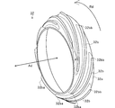
- FIG. 2 is a schematic perspective view of the baffle in the present embodiment.
- FIG. 3 is a schematic side view of the compressor impeller according to the present embodiment.
- FIG. 4 is an extraction diagram of a broken line portion in FIG.
- FIG. 5 is a schematic perspective view of a baffle according to a modification.
- FIG. 1 is a schematic sectional view of the supercharger TC.
- the direction of arrow L shown in FIG. 1 will be described as the left side of the supercharger TC.
- the direction of arrow R shown in FIG. 1 will be described as the right side of the supercharger TC.
- a compressor housing 6 described later functions as a centrifugal compressor CC.
- a supercharger TC will be described as an example of the centrifugal compressor CC.
- the centrifugal compressor CC is not limited to the supercharger TC.
- the centrifugal compressor CC may be incorporated in a device other than the supercharger TC, or may be a single unit.
- the supercharger TC includes a supercharger main body 1.
- the supercharger body 1 includes a bearing housing 2, a turbine housing 4, and a compressor housing 6.
- the turbine housing 4 is connected to the left side of the bearing housing 2 by a fastening bolt 8.
- the compressor housing 6 is connected to the right side of the bearing housing 2 by a fastening bolt 10.
- FIG. 1 shows a full floating bearing as an example of the bearing 14.
- the bearing 14 may be another radial bearing such as a semi-floating bearing or a rolling bearing.
- the shaft 12 is rotatably supported by a bearing 14.
- a turbine impeller 16 is provided at the left end of the shaft 12.
- the turbine impeller 16 is rotatably housed in the turbine housing 4.
- a compressor impeller 18 is provided at the right end of the shaft 12.
- the compressor impeller 18 is rotatably housed in the compressor housing 6.
- the main passage 20 is formed in the compressor housing 6.
- the main flow path 20 opens to the right of the supercharger TC.
- the main flow path 20 is formed on the upstream side (front side) of the compressor impeller 18.
- the main flow path 20 extends in a direction in which the rotation axis of the compressor impeller 18 extends (hereinafter, simply referred to as an axial direction).
- the main flow path 20 is connected to an air cleaner (not shown).
- the compressor impeller 18 is provided in the main flow path 20.
- the centrifugal compressor CC of the present embodiment includes the compressor housing 6, the compressor impeller 18, and a baffle 32 described later.
- a diffuser passage 22 is formed by the facing surfaces of the bearing housing 2 and the compressor housing 6.
- the diffuser channel 22 pressurizes air.
- the diffuser channel 22 is formed in an annular shape.
- the diffuser flow path 22 communicates with the main flow path 20 via the compressor impeller 18 on the radially inner side.
- a compressor scroll channel 24 is provided in the compressor housing 6.
- the compressor scroll channel 24 is formed in an annular shape.
- the compressor scroll flow path 24 is located, for example, radially outward of the shaft 12 from the diffuser flow path 22.
- the compressor scroll passage 24 communicates with an intake port of an engine (not shown) and the diffuser passage 22.
- the intake air flows in the compressor housing 6 (main flow path 20) from the upstream side (the right side in FIG. 1) to the downstream side (the left side in FIG. 1).
- the intake air is pressurized and accelerated in a process of flowing between the blades of the compressor impeller 18.
- the pressurized and accelerated air is pressurized in the diffuser channel 22 and the compressor scroll channel 24.
- the pressurized air is led to the intake port of the engine.
- a discharge port 26 is formed in the turbine housing 4.
- the discharge port 26 opens to the left of the supercharger TC.
- the discharge port 26 is connected to an exhaust gas purification device (not shown).
- a communication passage 28 and a turbine scroll flow path 30 are formed in the turbine housing 4.
- the turbine scroll flow path 30 is formed in an annular shape.
- the turbine scroll passage 30 is located, for example, radially outside the turbine impeller 16 with respect to the communication passage 28.
- the turbine scroll channel 30 communicates with a gas inlet (not shown). Exhaust gas discharged from an exhaust manifold (not shown) of the engine is guided to the gas inlet.
- the communication path 28 connects the turbine scroll flow path 30 and the discharge port 26 via the turbine impeller 16.
- the exhaust gas guided from the gas inlet to the turbine scroll flow path 30 is guided to the discharge port 26 via the communication path 28 and the turbine impeller 16.
- the exhaust gas guided to the discharge port 26 rotates the turbine impeller 16 during the circulation process.
- the compressor housing 6 has a cylindrical portion 6a.
- a main flow path 20 is formed on the inner peripheral surface of the cylindrical portion 6a.
- the main flow path 20 is provided with an upstream throttle portion (first throttle portion) 6b, a parallel portion 6c, and a downstream throttle portion (second throttle portion) 6d.
- the upstream throttle portion 6b is continuous with the opening of the cylindrical portion 6a.
- the upstream throttle portion 6b has an inner diameter that decreases toward the compressor impeller 18 side.
- the cross-sectional area of the flow path of the upstream throttle portion 6b decreases as approaching the compressor impeller 18.
- the upstream throttle portion 6b reduces the cross-sectional area of the main flow path 20 to the first cross-sectional area.
- the parallel portion 6c is parallel to the axial direction.
- the parallel portion 6c is continuous from the upstream throttle portion 6b to the compressor impeller 18 side.
- the inner diameter of the downstream throttle portion 6d decreases toward the compressor impeller 18 side.
- the flow path cross-sectional area of the downstream throttle portion 6 d decreases as it approaches the compressor impeller 18.
- the downstream throttle portion 6d reduces the flow path cross-sectional area of the main flow path 20 to a second flow path cross-sectional area smaller than the first flow path cross-sectional area.
- the downstream throttle portion 6d continues from the parallel portion 6c to the compressor impeller 18 side.
- the downstream throttle portion 6d is located closer to the compressor impeller 18 than the upstream throttle portion 6b.
- the upstream throttle portion 6b, the parallel portion 6c, and the downstream throttle portion 6d are arranged upstream (front side) of the compressor impeller 18.
- a baffle attachment (not shown) is attached to the opening 6aa of the cylindrical portion 6a.
- a baffle 32 is arranged on the inner diameter side of the upstream throttle portion 6b by attaching a baffle attachment portion (not shown).
- the baffle 32 is fastened to the opening surface 6aa of the cylindrical portion 6a by a fastening member, for example.
- the baffle 32 may be attached to the inner peripheral surface of the upstream throttle portion 6b.
- the baffle 32 may be attached to the inner peripheral surface of the upstream throttle portion 6b by bonding, welding, or press fitting.
- FIG. 2 is a schematic perspective view of the baffle 32 in the present embodiment.
- the baffle 32 has a partition wall 32a and a protrusion 32b.
- the separating partition part 32a has a conical cylindrical shape.
- the separation wall portion 32a faces the inner peripheral surface of the upstream throttle portion 6b.
- the separation wall portion 32a is disposed with a gap between the separation wall portion 32a and the inner peripheral surface of the upstream throttle portion 6b.
- the separation wall portion 32a has an outer peripheral surface parallel to the inner peripheral surface of the upstream throttle portion 6b. Accordingly, the outer diameter of the separation wall portion 32a decreases toward the compressor impeller 18 side. However, the outer peripheral surface of the separation wall portion 32a may not be parallel to the inner peripheral surface of the upstream throttle portion 6b.
- the separation wall portion 32a has an inner peripheral surface parallel to the inner peripheral surface of the upstream throttle portion 6b. Therefore, the inner diameter of the separation wall portion 32a decreases toward the compressor impeller 18 side. However, the inner peripheral surface of the separation wall portion 32a may not be parallel to the inner peripheral surface of the upstream throttle portion 6b.
- At least one projection 32b is formed on the outer peripheral surface of the separation partition 32a.
- the protruding portion 32b protrudes from the outer peripheral surface of the separation wall portion 32a in a direction approaching the inner peripheral surface of the upstream throttle portion 6b.
- the protrusion 32b protrudes in a direction perpendicular to the outer peripheral surface of the separation wall 32a.
- the protrusion 32b does not have to protrude in a direction perpendicular to the outer peripheral surface of the separation wall 32a.
- the protrusion 32b may protrude in the radial direction of the compressor impeller 18 from the outer peripheral surface of the separation wall 32a.
- the protrusion 32b contacts the inner peripheral surface of the upstream throttle 6b.
- the protrusion 32b may not be in contact with the inner peripheral surface of the upstream throttle portion 6b.
- a plurality of protrusions 32b are formed apart from each other in a rotation direction (hereinafter, simply referred to as a rotation direction) Rd of the compressor impeller 18.
- the plurality of protrusions 32b are formed at equal intervals in the rotation direction Rd.
- the plurality of protrusions 32b may be formed at irregular intervals in the rotation direction Rd.
- the projection 32b has a tip 32ba on the side close to the compressor impeller 18 (hereinafter simply referred to as the downstream side).
- the protrusion 32b has a rear end 32bb on a side separated from the compressor impeller 18 (hereinafter, simply referred to as an upstream side).
- the front end 32ba of the protrusion 32b is separated from the rear end 32bb of the protrusion 32b in the axial direction Ad.
- the front end 32ba of the protrusion 32b is provided at a position different from the rear end 32bb in the rotation direction Rd.
- the front end 32ba of the protrusion 32b is provided upstream of the rear end 32bb in the rotation direction Rd.
- the protrusion 32b extends in the axial direction Ad and the rotational direction Rd.
- the extending direction of the protrusion 32b is inclined at an angle ⁇ with respect to the rotation direction Rd.
- the plurality of protrusions 32b are formed over the entire circumference of the separation wall 32a while having portions facing each other in the axial direction Ad. Two or more protrusions 32b exist in the axial direction Ad over the entire circumference of the separation wall 32a. That is, there is no single phase angle of the protrusion 32b in the axial direction Ad.
- FIG. 3 is a schematic side view of the compressor impeller 18 in the present embodiment.
- the blade 18a of the compressor impeller 18 has an outer diameter that decreases from the downstream side (left side in FIG. 3) to the upstream side (right side in FIG. 3).
- the blade 18a of the compressor impeller 18 has the smallest outer diameter (minimum outer diameter) at the upstream end (front edge).
- the blade 18a of the compressor impeller 18 has a long blade 18aa and a short blade 18ab.
- the long blade 18aa is longer in the axial direction Ad than the short blade 18ab.
- the leading edge of the long blade 18aa is located on the upstream side of the main flow path 20 from the leading edge of the short blade 18ab.
- the outer diameter of the leading edge of the long blade 18aa has the smallest outer diameter (minimum outer diameter) among the blades 18a of the compressor impeller 18.
- the extension direction (tangent line) from the front edge of the outer peripheral surface of the long blade 18aa is inclined toward the rotation direction Rd with respect to the axial direction Ad.
- the extending direction (tangent line) from the front edge of the outer peripheral surface of the long blade 18aa is inclined at an angle ⁇ with respect to the rotation direction Rd.
- the inclination angle ⁇ of the protrusion 32b of the baffle 32 is smaller than the inclination angle ⁇ of the long blade 18aa.
- the air may flow backward on the upstream side of the compressor impeller 18 under the operating condition on the small flow rate side.
- the air that has flowed back to the upstream side of the compressor impeller 18 moves in a direction away from the compressor impeller 18 along the inner peripheral surface of the cylindrical portion 6a (to the right in FIG. 1).
- the backflow air flows into the space between the inner peripheral surface of the upstream throttle portion 6b and the outer peripheral surface of the separation wall portion 32a.
- the protrusion 32b of the baffle 32 is arranged in a space between the inner peripheral surface of the upstream throttle portion 6b and the outer peripheral surface of the separation wall portion 32a.
- the backflow air flows into the space on the outer peripheral surface side where the protrusion 32b of the baffle 32 is arranged.
- the backflow air flows into the space on the outer peripheral surface side of the baffle 32, thereby reducing the influence on the space on the inner peripheral surface side of the baffle 32. That is, the backflow air flows into the space on the outer peripheral surface side of the baffle 32, thereby reducing the influence on the air flowing from the upstream side to the downstream side in the space (main flow path 20) on the inner peripheral surface side of the baffle 32.
- the baffle 32 can expand the operation area on the small flow rate side of the supercharger TC.
- the backflow air rotates in a direction inclined at an inclination angle ⁇ with respect to the rotation direction Rd.
- the rotated backflow air flows into the space on the outer peripheral surface side of the baffle 32 where the protrusion 32b is arranged.
- the inclination angle ⁇ of the projection 32b is set smaller than the inclination angle ⁇ . Therefore, the backflow air contacts the wall surface (side surface) of the protrusion 32b.
- the inclination angle ⁇ smaller than the inclination angle ⁇
- the contact area between the backflow air and the side wall of the projection 32b can be made larger than when the inclination angle ⁇ is equal to the inclination angle ⁇ .
- the backflow air can be decelerated by increasing the contact area. That is, the protrusion 32b can reduce the backflow of air upstream of the baffle 32.
- the interval between the portion of the protrusion 32b that is the most distant from the compressor impeller 18 and the portion facing the axial direction Ad is the portion of the protrusion 32b that is closest to the compressor impeller 18 and the portion that faces the axial direction Ad. May be larger than the interval.
- the distance between the protrusion 32b and a portion facing the axial direction Ad increases in the direction away from the compressor impeller 18.
- the distance between the inner peripheral surface of the upstream throttle portion 6b and the outer peripheral surface of the separation wall portion 32a may be set larger on the upstream side than on the downstream side. That is, the interval between the inner peripheral surface of the upstream throttle portion 6b and the outer peripheral surface of the separation wall portion 32a may be set to be larger on the side separated from the compressor impeller 18 than on the side close to the compressor impeller 18. Accordingly, the space between the inner peripheral surface of the upstream throttle portion 6b and the outer peripheral surface of the separation wall portion 32a is larger on the upstream side than on the downstream side.
- the backflow air can be decelerated more than in the case where the distance between the outer peripheral surface of the separation wall portion 32a and the inner peripheral surface of the upstream throttle portion 6b is constant. it can. That is, the baffle 32 can reduce the backflow of air upstream of the baffle 32.
- the baffle 32 reduces the backflow of air upstream of the baffle 32 under the operating condition on the small flow rate side of the supercharger TC. As a result, the baffle 32 can expand the operation area on the small flow rate side of the supercharger TC.
- FIG. 4 is an extraction diagram of a broken line portion in FIG. ⁇ 1 is the smallest inner diameter of the downstream throttle portion 6d.
- the inner diameter ⁇ 1 is the inner diameter of the downstream end of the downstream throttle section 6d.
- the inner diameter ⁇ 1 is the smallest of the inner diameters of the cylindrical portions 6a forming the main flow path 20.
- ⁇ 2 is the largest inner diameter of the downstream throttle portion 6d.
- the inside diameter ⁇ 2 is the inside diameter of the upstream end of the downstream throttle section 6d.
- the inner diameter ⁇ 2 is the inner diameter of the parallel portion 6c.
- the inside diameter ⁇ 2 is the smallest inside diameter of the upstream throttle portion 6b.
- the inner diameter ⁇ 2 is the inner diameter of the downstream end of the upstream throttle section 6b.
- ⁇ 3 is the smallest inside diameter of the baffle 32.
- the inside diameter ⁇ 3 is the inside diameter of the end on the downstream side (the left side in FIG. 4) of the inner peripheral surface of the baffle 32.
- the inner diameter ⁇ 1 is smaller than the inner diameter ⁇ 2.
- the inner diameter ⁇ 2 is smaller than the inner diameter ⁇ 3.
- the minimum inner diameter ⁇ 3 of the baffle 32 is larger than the minimum inner diameter ⁇ 2 of the upstream throttle portion 6b. That is, the baffle 32 does not protrude toward the inner diameter side from the upstream throttle portion 6b.
- the minimum inner diameter ⁇ 3 of the baffle 32 may be the same as the minimum inner diameter ⁇ 2 of the upstream throttle portion 6b. By attaching the baffle 32 to the inclined surface of the upstream throttle portion 6b, the minimum inner diameter ⁇ 3 of the baffle 32 can be made larger than the minimum inner diameter ⁇ 2 of the upstream throttle portion 6b.
- the minimum inner diameter ⁇ 3 of the baffle 32 may be smaller than the minimum inner diameter ⁇ 2 of the upstream throttle portion 6b. However, the minimum inner diameter ⁇ 3 of the baffle 32 is larger than the minimum inner diameter ⁇ 1 of the downstream throttle portion 6d. That is, the baffle 32 does not protrude toward the inner diameter side from the downstream throttle portion 6d. In other words, the inner peripheral surface of the downstream throttle portion 6d protrudes radially inward of the compressor impeller 18 from the inner peripheral surface of the baffle 32 (separation wall portion 32a).
- the minimum inner diameter ⁇ 3 of the baffle 32 is set to be larger than the minimum inner diameter ⁇ 1 of the downstream throttle portion 6d.
- the baffle 32 can slowly decelerate the air flowing backward from the compressor impeller 18. Thereby, the baffle 32 can shift the limit flow rate at which surging occurs to the smaller flow rate side. Further, since the baffle 32 is attached to the upstream throttle portion 6b, it does not protrude toward the inner diameter side than the upstream throttle portion 6b (downstream throttle portion 6d). Thereby, the baffle 32 can maintain the flow rate at the limit where the choke occurs.
- FIG. 5 is a schematic perspective view of a baffle 132 according to a modification. Constituent elements that are substantially the same as the supercharger TC of the above embodiment are given the same reference numerals, and description thereof is omitted.
- the supercharger TC of the modified example includes a baffle 132 instead of the baffle 32 of the above embodiment.
- the baffle 132 of the present modified example will be described.
- the baffle 132 has a separation wall 132a and a protrusion 132b.
- the separation wall 132a has a conical cylindrical shape.
- the separating partition part 132a faces the inner peripheral surface of the upstream throttle part 6b.
- the separation wall 132a is disposed with a gap between the separation wall 132a and the inner peripheral surface of the upstream throttle 6b.
- the separation partition part 132a has an outer peripheral surface parallel to the inner peripheral surface of the upstream throttle part 6b. Therefore, the outer diameter of the separation wall portion 132a decreases toward the compressor impeller 18 side. However, the outer peripheral surface of the separation wall 132a may not be parallel to the inner peripheral surface of the upstream throttle 6b.
- the separation partition part 132a has an inner peripheral surface parallel to the inner peripheral surface of the upstream throttle part 6b. Accordingly, the inner diameter of the separation wall 132a decreases toward the compressor impeller 18 side. However, the inner peripheral surface of the separation wall 132a may not be parallel to the inner peripheral surface of the upstream throttle portion 6b.
- the distance between the inner peripheral surface of the upstream throttle portion 6b and the outer peripheral surface of the separation wall portion 132a may be set to be larger on the upstream side than on the downstream side.
- the space between the inner peripheral surface of the upstream throttle portion 6b and the outer peripheral surface of the separation wall portion 132a is larger on the upstream side than on the downstream side.
- At least one protrusion 132b is formed on the outer peripheral surface of the separation partition 132a.
- the protrusion 132b protrudes from the outer peripheral surface of the separating partition 132a in a direction approaching the inner peripheral surface of the upstream throttle portion 6b.
- the projection 132b projects in a direction perpendicular to the outer peripheral surface of the separation wall 132a.
- the protrusion 132b does not have to protrude in a direction perpendicular to the outer peripheral surface of the separation wall 132a.
- the protrusion 132b may protrude from the outer peripheral surface of the separation wall 132a in the radial direction of the compressor impeller 18.
- the protrusion 132b contacts the inner peripheral surface of the upstream throttle 6b.
- the protrusion 132b may not be in contact with the inner peripheral surface of the upstream throttle portion 6b.
- the projection 132b is spiral.
- the protrusion 132b extends in the axial direction Ad and the rotational direction Rd.
- the extending direction of the protrusion 132b is inclined at an angle ⁇ with respect to the rotation direction Rd.
- the inclination angle ⁇ of the projection 132b of this modification is smaller than the inclination angle ⁇ of the projection 32b of the above embodiment.
- the projection 132b has a length that makes three rounds on the outer peripheral surface of the separation wall 132a.
- the length of the protrusion 132b in the rotation direction Rd may be at least one circumference of the outer peripheral surface of the separation wall 132a.
- the protrusion 132b extends one or more turns in the rotation direction Rd of the compressor impeller 18.
- the protruding portions 132b have portions facing each other spaced apart in the axial direction Ad.
- the protruding portion 132b is formed over the entire circumference of the separating partition portion 132a while having portions facing each other in the axial direction Ad.
- a single (one) projection 132b is formed on the outer peripheral surface of the separation wall 132a.
- a plurality of protrusions 132b may be formed on the outer peripheral surface of the separation wall 132a. In that case, at least one projection 132b extends one or more turns in the rotation direction Rd of the compressor impeller 18.
- the interval between the projections 132b in the axial direction Ad is constant.
- the interval between the projections 132b in the axial direction Ad may not be constant.
- the interval between the part of the protrusion 132b that is the most distant from the compressor impeller 18 and the part facing the axial direction Ad is the part of the protrusion 132b that is closest to the compressor impeller 18 and the part that faces the axial direction Ad. May be larger than the interval.
- the distance between the protrusions 132b in the axial direction Ad may increase in the direction away from the compressor impeller 18.
- the air flowing backward from the compressor impeller 18 can be decelerated as compared with the case where the opposing interval of the protruding portion 132b is fixed. That is, the protrusion 132b can reduce the backflow of air upstream of the baffle 132.
- the baffle 132 of the present modified example can have a larger contact area between the air flowing backward from the compressor impeller 18 and the side wall of the projection 132b than the baffle 32 of the above embodiment.
- the air flowing backward from the compressor impeller 18 can be decelerated more than in the above embodiment.
- the limit flow rate at which surging occurs can be shifted to a smaller flow rate side than in the above embodiment.
- the baffle 132 of the present modification has a smaller number of protrusions 132b than the baffle 32 of the above embodiment. Therefore, the baffle 132 of the present modification can reduce the pressure loss due to the separation vortex generated when the air passes through the protrusion 132b, as compared with the baffle 32 of the above embodiment. That is, the baffle 132 of the present modification can further reduce the pressure loss when air flows from the upstream side to the downstream side as compared with the baffle 32 of the above embodiment.
- the baffle 32 of the above embodiment and the baffle 132 of the above modification may be combined. That is, the projection 32b and the projection 132b may be mixed on the outer peripheral surface of the baffle 32.
- the present invention is not limited to this, and the protrusions 32b and 132b may be formed on the inner peripheral surface of the upstream throttle portion 6b.
- the protrusions 32b and 132b may include a protrusion formed on the inner peripheral surface of the upstream throttle portion 6b and a protrusion formed on the outer peripheral surface of the baffles 32 and 132. That is, the projections 32b and 132b may protrude from at least one of the inner peripheral surface of the upstream throttle portion 6b and the outer peripheral surface of the separation partition portions 32a and 132a. Further, the protrusions 32b and 132b may protrude in a direction in which the inner peripheral surface of the upstream throttle portion 6b and the outer peripheral surface of the separation wall portion 32a approach each other.
- the present invention is not limited to this, and the baffles 32 and 132 may be provided in the downstream throttle portion 6d.
- the present disclosure can be used for a centrifugal compressor.
- CC centrifugal compressor $ 6b: upstream throttle (throttle, first throttle) $ 6d: downstream throttle (throttle, second throttle) $ 18: compressor impeller $ 20: main channel $ 32: baffle @ 32a: Separating partition portion # 32b: Projecting portion 132: Baffle # 132a: Separating partition portion 132b: Projecting portion
Landscapes
- Engineering & Computer Science (AREA)
- Mechanical Engineering (AREA)
- General Engineering & Computer Science (AREA)
- Structures Of Non-Positive Displacement Pumps (AREA)
- Supercharger (AREA)
Abstract
遠心圧縮機(CC)は、コンプレッサインペラ(18)に近づくにつれて流路断面積が縮小する上流側絞り部(6b)と、上流側絞り部の内周面と対向し、上流側絞り部の内周面との間に隙間を有して配される離隔壁部(32a)と、上流側絞り部の内周面および離隔壁部の外周面の少なくともいずれかから突出する突起部(32b)と、を備える。
Description
本開示は、遠心圧縮機に関する。本出願は2018年8月23日に提出された日本特許出願第2018-156431号に基づく優先権の利益を主張するものであり、その内容は本出願に援用される。
過給機は、圧縮機(コンプレッサ)を備える。圧縮機は、コンプレッサハウジングと、コンプレッサインペラとを含んで構成される。コンプレッサハウジングには、コンプレッサインペラに空気(吸気)を導く吸気通路が形成される。コンプレッサハウジングには、コンプレッサインペラの外周側にシュラウド部が形成される。特許文献1では、シュラウド部に環状の空気室が形成されている。シュラウド部には、吸気通路と空気室とを連通する吸込連通路および吹出連通路が形成される。吸込連通路は、コンプレッサインペラの外径側に形成される。吹出連通路は、コンプレッサインペラより吸気通路の上流側に形成される。吸込連通路、空気室、および、吹出連通路は、循環流路を形成する。循環流路により、過給機の小流量側の作動領域が拡大する。
しかし、循環流路を形成した場合、過給機の大流量側の作動領域が縮小される。したがって、特許文献1では、過給機の作動領域を拡大することが困難であった。
本開示の目的は、過給機の作動領域を拡大することが可能な遠心圧縮機を提供することである。
上記課題を解決するために、本開示の一態様に係る遠心圧縮機は、コンプレッサインペラと、コンプレッサインペラの正面側に形成される主流路と、主流路に設けられ、コンプレッサインペラに近づくにつれて流路断面積が縮小する絞り部と、絞り部の内周面と対向し、絞り部の内周面との間に隙間を有して配される離隔壁部と、絞り部の内周面および離隔壁部の外周面の少なくともいずれかから突出する突起部と、を備える。
突起部は、コンプレッサインペラの軸方向に離隔して互いに対向する部位を有してもよい。
コンプレッサインペラの回転方向に1周以上延在する突起部を含んでもよい。
突起部は、コンプレッサインペラの軸方向に離隔して互いに対向する部位があり、突起部のうちコンプレッサインペラから最も離隔する部位と軸方向に対向する部位との間隔は、突起部のうちコンプレッサインペラに最も近接する部位と軸方向に対向する部位との間隔よりも大きくてもよい。
絞り部の内周面と離隔壁部の外周面との間隔は、コンプレッサインペラに近接する側よりも、コンプレッサインペラから離隔する側が大きくてもよい。
主流路に設けられ、絞り部よりもコンプレッサインペラ側に位置し、離隔壁部の内周面よりもコンプレッサインペラの径方向内側に内周面が突出する第2の絞り部を備えてもよい。
本開示によれば、過給機の作動領域を拡大することができる。
以下に添付図面を参照しながら、本開示の実施形態について詳細に説明する。実施形態に示す寸法、材料、その他具体的な数値等は、理解を容易とするための例示にすぎず、特に断る場合を除き、本開示を限定するものではない。なお、本明細書および図面において、実質的に同一の機能、構成を有する要素については、同一の符号を付することにより重複説明を省略する。また本開示に直接関係のない要素は図示を省略する。
図1は、過給機TCの概略断面図である。以下では、図1に示す矢印L方向を過給機TCの左側として説明する。図1に示す矢印R方向を過給機TCの右側として説明する。過給機TCのうち、後述するコンプレッサハウジング6側は、遠心圧縮機CCとして機能する。以下では、遠心圧縮機CCの一例として、過給機TCについて説明する。ただし、遠心圧縮機CCは、過給機TCに限られない。遠心圧縮機CCは、過給機TC以外の装置に組み込まれてもよいし、単体であってもよい。
図1に示すように、過給機TCは、過給機本体1を備えて構成される。過給機本体1は、ベアリングハウジング2と、タービンハウジング4と、コンプレッサハウジング6とを含んで構成される。タービンハウジング4は、ベアリングハウジング2の左側に締結ボルト8によって連結される。コンプレッサハウジング6は、ベアリングハウジング2の右側に締結ボルト10によって連結される。
ベアリングハウジング2には、軸受孔2aが形成される。軸受孔2aは、過給機TCの左右方向に貫通する。軸受孔2aは、シャフト12の一部を収容する。軸受孔2aには、軸受14が収容される。図1では、軸受14の一例としてフルフローティング軸受を示す。ただし、軸受14は、セミフローティング軸受や転がり軸受など、他のラジアル軸受であってもよい。シャフト12は、軸受14によって、回転自在に軸支される。シャフト12の左端部には、タービンインペラ16が設けられる。タービンインペラ16は、タービンハウジング4に回転自在に収容される。シャフト12の右端部には、コンプレッサインペラ18が設けられる。コンプレッサインペラ18は、コンプレッサハウジング6に回転自在に収容される。
コンプレッサハウジング6には、主流路20が形成される。主流路20は、過給機TCの右側に開口する。主流路20は、コンプレッサインペラ18の上流側(正面側)に形成される。主流路20は、コンプレッサインペラ18の回転軸が延びる方向(以下、単に軸方向と称す)に延在する。主流路20は、不図示のエアクリーナに接続される。コンプレッサインペラ18は、主流路20に配される。本実施形態の遠心圧縮機CCは、コンプレッサハウジング6と、コンプレッサインペラ18と、後述するバッフル32とを含んで構成される。
ベアリングハウジング2とコンプレッサハウジング6の対向面によって、ディフューザ流路22が形成される。ディフューザ流路22は、空気を昇圧する。ディフューザ流路22は、環状に形成される。ディフューザ流路22は、径方向内側において、コンプレッサインペラ18を介して主流路20に連通している。
コンプレッサハウジング6には、コンプレッサスクロール流路24が設けられる。コンプレッサスクロール流路24は、環状に形成される。コンプレッサスクロール流路24は、例えば、ディフューザ流路22よりもシャフト12の径方向外側に位置する。コンプレッサスクロール流路24は、不図示のエンジンの吸気口と、ディフューザ流路22とに連通している。コンプレッサインペラ18が回転すると、コンプレッサハウジング6内に空気が吸気される。吸気された空気は、上流側(図1中、右側)から下流側(図1中、左側)に向かってコンプレッサハウジング6内(主流路20)を流通する。吸気された空気は、コンプレッサインペラ18の翼間を流通する過程において加圧加速される。加圧加速された空気は、ディフューザ流路22およびコンプレッサスクロール流路24で昇圧される。昇圧された空気は、エンジンの吸気口に導かれる。
タービンハウジング4には、吐出口26が形成される。吐出口26は、過給機TCの左側に開口する。吐出口26は、不図示の排気ガス浄化装置に接続される。また、タービンハウジング4には、連通路28と、タービンスクロール流路30とが形成される。タービンスクロール流路30は、環状に形成される。タービンスクロール流路30は、例えば、連通路28よりもタービンインペラ16の径方向外側に位置する。タービンスクロール流路30は、不図示のガス流入口と連通する。ガス流入口には、不図示のエンジンの排気マニホールドから排出される排気ガスが導かれる。連通路28は、タービンインペラ16を介してタービンスクロール流路30と吐出口26とを連通させる。ガス流入口からタービンスクロール流路30に導かれた排気ガスは、連通路28およびタービンインペラ16を介して吐出口26に導かれる。吐出口26に導かれた排気ガスは、流通過程においてタービンインペラ16を回転させる。
タービンインペラ16の回転力は、シャフト12を介してコンプレッサインペラ18に伝達される。コンプレッサインペラ18が回転すると、上記のとおりに空気が昇圧される。こうして、空気がエンジンの吸気口に導かれる。
コンプレッサハウジング6は、円筒部6aを有する。円筒部6aの内周面には、主流路20が形成される。主流路20には、上流側絞り部(第1の絞り部)6b、平行部6c、下流側絞り部(第2の絞り部)6dが設けられる。上流側絞り部6bは、円筒部6aの開口に連続する。
上流側絞り部6bは、コンプレッサインペラ18側に向かって内径が小さくなる。上流側絞り部6bは、コンプレッサインペラ18に近づくにつれて流路断面積が縮小する。上流側絞り部6bは、主流路20の流路断面積を第1流路断面積に縮小する。平行部6cは、軸方向に平行である。平行部6cは、上流側絞り部6bからコンプレッサインペラ18側に連続する。下流側絞り部6dは、コンプレッサインペラ18側に向かって内径が小さくなる。下流側絞り部6dは、コンプレッサインペラ18に近づくにつれて流路断面積が縮小する。下流側絞り部6dは、主流路20の流路断面積を第1流路断面積よりも小さい第2流路断面積に縮小する。下流側絞り部6dは、平行部6cからコンプレッサインペラ18側に連続する。下流側絞り部6dは、上流側絞り部6bよりもコンプレッサインペラ18側に位置する。
上流側絞り部6b、平行部6c、下流側絞り部6dは、コンプレッサインペラ18より上流側(正面側)に配される。円筒部6aの開口面6aaには、不図示のバッフル取付部が取り付けられる。不図示のバッフル取付部が取り付けられることにより、上流側絞り部6bの内径側には、バッフル32が配される。バッフル32は、例えば、円筒部6aの開口面6aaに締結部材により締結される。ただし、バッフル32は、上流側絞り部6bの内周面に取り付けられてもよい。例えば、バッフル32は、上流側絞り部6bの内周面に接着、溶接、あるいは、圧入により取り付けられてもよい。
図2は、本実施形態におけるバッフル32の概略斜視図である。バッフル32は、離隔壁部32aと、突起部32bとを有する。離隔壁部32aは、円錐筒形状である。離隔壁部32aは、上流側絞り部6bの内周面と対向する。離隔壁部32aは、上流側絞り部6bの内周面との間に隙間を有して配される。離隔壁部32aは、上流側絞り部6bの内周面と平行な外周面を有する。したがって、離隔壁部32aは、コンプレッサインペラ18側に向かって外径が小さくなる。ただし、離隔壁部32aの外周面は、上流側絞り部6bの内周面と平行でなくてもよい。
離隔壁部32aは、上流側絞り部6bの内周面と平行な内周面を有する。したがって、離隔壁部32aは、コンプレッサインペラ18側に向かって内径が小さくなる。ただし、離隔壁部32aの内周面は、上流側絞り部6bの内周面と平行でなくてもよい。
離隔壁部32aの外周面には、少なくとも1つの突起部32bが形成される。突起部32bは、離隔壁部32aの外周面から上流側絞り部6bの内周面に近接する方向に突出する。本実施形態では、突起部32bは、離隔壁部32aの外周面から垂直な方向に突出する。しかし、突起部32bは、離隔壁部32aの外周面から垂直な方向に突出していなくてもよい。例えば、突起部32bは、離隔壁部32aの外周面からコンプレッサインペラ18の径方向に突出していてもよい。突起部32bは、上流側絞り部6bの内周面と接触する。ただし、突起部32bは、上流側絞り部6bの内周面と非接触であってもよい。
本実施形態では、突起部32bは、コンプレッサインペラ18の回転方向(以下、単に回転方向と称す)Rdに離隔して複数形成される。複数の突起部32bは、回転方向Rdに等間隔で形成される。ただし、複数の突起部32bは、回転方向Rdに不等間隔で形成されてもよい。
突起部32bは、コンプレッサインペラ18に近接する側(以下、単に下流側と称す)に先端部32baを有する。突起部32bは、コンプレッサインペラ18から離隔する側(以下、単に上流側と称す)に後端部32bbを有する。突起部32bの先端部32baは、突起部32bの後端部32bbと軸方向Adに離隔している。突起部32bの先端部32baは、回転方向Rdにおいて後端部32bbと異なる位置に設けられる。突起部32bの先端部32baは、後端部32bbより回転方向Rdの上流側に設けられる。突起部32bは、軸方向Adおよび回転方向Rdに延在する。突起部32bの延在方向は、回転方向Rdに対し角度αで傾斜している。
先端部32baが位置する回転方向Rdの位相(角度)においては、1つの先端部32baの軸方向Adの上流側に2つの突起部32bが存在している。後端部32bbが位置する回転方向Rdの位相(角度)においては、1つの後端部32bbの軸方向Adの下流側に2つの突起部32bが存在している。突起部32bは、先端部32baと後端部32bbとの間に中間部を有する。中間部が位置する回転方向Rdの位相(角度)においては、1つの中間部の軸方向Adの上流側あるいは下流側に1つの突起部32bが存在している。つまり、突起部32bは、軸方向Adに離隔して互いに対向する部位を有する。複数の突起部32bは、軸方向Adに互いに対向する部位を有しながら、離隔壁部32aの全周に亘って形成される。離隔壁部32aの全周に亘って2以上の突起部32bが軸方向Adに存在する。つまり、突起部32bが軸方向Adに1つのみの位相角度はない。
図3は、本実施形態におけるコンプレッサインペラ18の概略側面図である。コンプレッサインペラ18の羽根18aは、下流側(図3中、左側)から上流側(図3中、右側)に向かって小さくなる外径を有する。コンプレッサインペラ18の羽根18aは、上流側の端部(前縁端)において最も小さい外径(最小外径)を有する。
コンプレッサインペラ18の羽根18aは、長羽根18aaと、短羽根18abとを有する。長羽根18aaは、短羽根18abよりも軸方向Adに長い。長羽根18aaの前縁端は、短羽根18abの前縁端よりも主流路20の上流側に位置する。長羽根18aaの前縁端の外径は、コンプレッサインペラ18の羽根18aのうち、最も小さい外径(最小外径)を有する。長羽根18aaの外周面の前縁端からの延長方向(接線)は、軸方向Adに対し、回転方向Rd側に傾斜している。長羽根18aaの外周面の前縁端からの延長方向(接線)は、回転方向Rdに対し角度βで傾斜している。ここで、バッフル32の突起部32bの傾斜角度αは、長羽根18aaの傾斜角度βより小さい角度である。
ところで、過給機TCは、小流量側の作動条件下において、コンプレッサインペラ18の上流側に空気が逆流する場合がある。コンプレッサインペラ18の上流側に逆流した空気(以下、単に逆流空気ともいう)は、円筒部6aの内周面に沿ってコンプレッサインペラ18から離隔する方向(図1中、右側)に移動する。逆流空気は、上流側絞り部6bの内周面と離隔壁部32aの外周面との間の空間に流入する。上流側絞り部6bの内周面と離隔壁部32aの外周面との間の空間には、バッフル32の突起部32bが配される。つまり、逆流空気は、バッフル32の突起部32bが配される外周面側の空間に流入する。逆流空気は、バッフル32の外周面側の空間に流入することで、バッフル32の内周面側の空間に与える影響が小さくなる。つまり、逆流空気は、バッフル32の外周面側の空間に流入することで、バッフル32の内周面側の空間(主流路20)を上流側から下流側に流れる空気に与える影響が小さくなる。その結果、バッフル32は、過給機TCの小流量側の作動領域を拡大することができる。
逆流空気は、回転方向Rdに対し傾斜角度βで傾斜した方向に回転する。回転した逆流空気は、バッフル32の突起部32bが配される外周面側の空間に流入する。ここで、突起部32bの傾斜角度αは、傾斜角度βより小さく設定されている。そのため、逆流空気は、突起部32bの壁面(側面)と接触する。傾斜角度αを傾斜角度βよりも小さい角度とすることで、傾斜角度αが傾斜角度βと等しい場合よりも、逆流空気と突起部32bの側壁との接触面積を大きくすることができる。接触面積を大きくすることで、逆流空気を減速させることができる。すなわち、突起部32bは、バッフル32よりも上流側に空気が逆流することを低減することができる。
また、突起部32bのうちコンプレッサインペラ18から最も離隔する部位と軸方向Adに対向する部位との間隔は、突起部32bのうちコンプレッサインペラ18に最も近接する部位と軸方向Adに対向する部位との間隔よりも大きくてもよい。具体的に、突起部32bは、軸方向Adに対向する部位との間隔(以下、単に対向間隔ともいう)が、コンプレッサインペラ18から離隔する方向に向かって大きくなる。突起部32bの下流側の対向間隔より上流側の対向間隔を大きくすることで、突起部32bの対向間隔が一定である場合よりも、逆流空気を減速させることができる。すなわち、突起部32bは、バッフル32よりも上流側に空気が逆流することを低減することができる。
また、上流側絞り部6bの内周面と離隔壁部32aの外周面との間隔は、下流側よりも上流側が大きく設定されてもよい。つまり、上流側絞り部6bの内周面と離隔壁部32aの外周面との間隔は、コンプレッサインペラ18に近接する側よりも、コンプレッサインペラ18から離隔する側が大きく設定されてもよい。これにより、上流側絞り部6bの内周面と離隔壁部32aの外周面との間の空間は、下流側よりも上流側の方が大きくなる。上流側の空間を下流側の空間より大きくすることで、離隔壁部32aの外周面と上流側絞り部6bの内周面との間隔が一定である場合よりも、逆流空気を減速させることができる。すなわち、バッフル32は、バッフル32よりも上流側に空気が逆流することを低減することができる。
このように、バッフル32は、過給機TCの小流量側の作動条件下において、バッフル32よりも上流側に空気が逆流することを低減する。その結果、バッフル32は、過給機TCの小流量側の作動領域を拡大することができる。
図4は、図1の破線部分の抽出図である。φ1は、下流側絞り部6dのうち最も小さい内径である。内径φ1は、下流側絞り部6dの下流側の端部の内径である。なお、内径φ1は、主流路20を形成する円筒部6aの内径のうち、最も小さい径である。φ2は、下流側絞り部6dのうち最も大きい内径である。内径φ2は、下流側絞り部6dの上流側の端部の内径である。
内径φ2は、平行部6cの内径である。内径φ2は、上流側絞り部6bのうち最も小さい内径である。内径φ2は、上流側絞り部6bの下流側の端部の内径である。φ3は、バッフル32のうち最も小さい内径である。内径φ3は、バッフル32の内周面の下流側(図4中、左側)の端部の内径である。
ここで、内径φ1は、内径φ2より小さい。内径φ2は、内径φ3より小さい。換言すれば、バッフル32の最小内径φ3は、上流側絞り部6bの最小内径φ2より大きい。つまり、バッフル32は、上流側絞り部6bより内径側に突出していない。上流側絞り部6bの傾斜面にバッフル32を取り付けることで、上流側絞り部6bから内径側にバッフル32を突出させ難くすることができる。
なお、バッフル32の最小内径φ3は、上流側絞り部6bの最小内径φ2と同じであってもよい。上流側絞り部6bの傾斜面にバッフル32を取り付けることで、バッフル32の最小内径φ3を上流側絞り部6bの最小内径φ2以上とすることができる。
なお、バッフル32の最小内径φ3は、上流側絞り部6bの最小内径φ2より小さくてもよい。ただし、バッフル32の最小内径φ3は、下流側絞り部6dの最小内径φ1より大きい。つまり、バッフル32は、下流側絞り部6dより内径側に突出しない。換言すれば、下流側絞り部6dの内周面は、バッフル32(離隔壁部32a)の内周面よりもコンプレッサインペラ18の径方向内側に突出している。
バッフル32が下流側絞り部6dより内径側に突出すると、主流路20の流路断面積(開口径)は、バッフル32により縮小される。主流路20の流路断面積(開口径)が縮小されると、過給機TCの大流量側の作動領域が縮小する。そのため、バッフル32の最小内径φ3は、下流側絞り部6dの最小内径φ1より大きくする。バッフル32の最小内径φ3を下流側絞り部6dの最小内径φ1より大きくすることで、過給機TCの大流量側の作動領域を維持することができる。
本実施形態によれば、バッフル32は、コンプレッサインペラ18から逆流した空気を緩慢に減速させることができる。これにより、バッフル32は、サージングが発生する限界の流量を小流量側へシフトさせることができる。また、バッフル32は、上流側絞り部6bに取り付けられることで、上流側絞り部6b(下流側絞り部6d)よりも内径側に突出しない。これにより、バッフル32は、チョークが発生する限界の流量を維持することができる。
(変形例)
図5は、変形例におけるバッフル132の概略斜視図である。上記実施形態の過給機TCと実質的に等しい構成要素については、同一の符号を付して説明を省略する。変形例の過給機TCは、上記実施形態のバッフル32に代えて、バッフル132を備える。以下、本変形例のバッフル132について説明する。
図5は、変形例におけるバッフル132の概略斜視図である。上記実施形態の過給機TCと実質的に等しい構成要素については、同一の符号を付して説明を省略する。変形例の過給機TCは、上記実施形態のバッフル32に代えて、バッフル132を備える。以下、本変形例のバッフル132について説明する。
バッフル132は、離隔壁部132aと、突起部132bとを有する。離隔壁部132aは、円錐筒形状である。離隔壁部132aは、上流側絞り部6bの内周面と対向する。離隔壁部132aは、上流側絞り部6bの内周面との間に隙間を有して配される。離隔壁部132aは、上流側絞り部6bの内周面と平行な外周面を有する。したがって、離隔壁部132aは、コンプレッサインペラ18側に向かって外径が小さくなる。ただし、離隔壁部132aの外周面は、上流側絞り部6bの内周面と平行でなくてもよい。
離隔壁部132aは、上流側絞り部6bの内周面と平行な内周面を有する。したがって、離隔壁部132aは、コンプレッサインペラ18側に向かって内径が小さくなる。ただし、離隔壁部132aの内周面は、上流側絞り部6bの内周面と平行でなくてもよい。
上流側絞り部6bの内周面と離隔壁部132aの外周面との間隔は、下流側よりも上流側が大きく設定されてもよい。これにより、上流側絞り部6bの内周面と離隔壁部132aの外周面との間の空間は、下流側よりも上流側の方が大きくなる。上流側の空間を下流側の空間より大きくすることで、離隔壁部132aの外周面と上流側絞り部6bの内周面との間隔が一定である場合よりも、コンプレッサインペラ18から逆流した空気を減速させることができる。すなわち、バッフル132は、バッフル132よりも上流側に空気が逆流することを低減することができる。
離隔壁部132aの外周面には、少なくとも1つの突起部132bが形成される。突起部132bは、離隔壁部132aの外周面から上流側絞り部6bの内周面に近接する方向に突出する。本変形例では、突起部132bは、離隔壁部132aの外周面から垂直な方向に突出する。しかし、突起部132bは、離隔壁部132aの外周面から垂直な方向に突出していなくてもよい。例えば、突起部132bは、離隔壁部132aの外周面からコンプレッサインペラ18の径方向に突出していてもよい。突起部132bは、上流側絞り部6bの内周面と接触する。ただし、突起部132bは、上流側絞り部6bの内周面と非接触であってもよい。
本変形例では、突起部132bは、螺旋状である。突起部132bは、軸方向Adおよび回転方向Rdに延在している。突起部132bの延在方向は、回転方向Rdに対し角度αで傾斜している。本変形例の突起部132bの傾斜角度αは、上記実施形態の突起部32bの傾斜角度αより小さい。本変形例では、突起部132bは、離隔壁部132aの外周面を3周する長さを有する。ただし、突起部132bの回転方向Rdの長さは、離隔壁部132aの外周面の1周以上の長さを有していればよい。すなわち、突起部132bは、コンプレッサインペラ18の回転方向Rdに1周以上延在している。突起部132bは、軸方向Adに離隔して互いに対向する部位を有する。突起部132bは、軸方向Adに互いに対向する部位を有しながら、離隔壁部132aの全周に亘って形成される。
本変形例では、突起部132bは、離隔壁部132aの外周面に単数(1つ)形成される。ただし、突起部132bは、離隔壁部132aの外周面に複数形成されてもよい。その場合、少なくとも1つの突起部132bは、コンプレッサインペラ18の回転方向Rdに1周以上延在している。
本変形例では、突起部132bの軸方向Adの対向間隔は、一定である。ただし、突起部132bの軸方向Adの対向間隔は、一定でなくてもよい。例えば、突起部132bのうちコンプレッサインペラ18から最も離隔する部位と軸方向Adに対向する部位との間隔は、突起部132bのうちコンプレッサインペラ18に最も近接する部位と軸方向Adに対向する部位との間隔よりも大きくてもよい。具体的に、突起部132bは、軸方向Adにおける対向間隔がコンプレッサインペラ18から離隔する方向に向かって大きくなってもよい。
突起部132bの上流側の対向間隔を下流側よりも大きくすることで、突起部132bの対向間隔を一定とした場合に比べて、コンプレッサインペラ18から逆流した空気を減速させることができる。すなわち、突起部132bは、バッフル132よりも上流側に空気が逆流することを低減することができる。
本変形例によれば、上記実施形態と同様の効果を得ることができる。また、本変形例のバッフル132は、上記実施形態のバッフル32よりも、コンプレッサインペラ18から逆流した空気と突起部132bの側壁との接触面積を大きくすることができる。
したがって、本変形例によれば、上記実施形態よりもコンプレッサインペラ18から逆流した空気を減速させることができる。これにより、本変形例は、上記実施形態よりもサージングが発生する限界の流量を小流量側へシフトさせることができる。
また、本変形例のバッフル132は、上記実施形態のバッフル32よりも、突起部132bの数が少ない。そのため、本変形例のバッフル132は、上記実施形態のバッフル32よりも、空気が突起部132bを通過する際に生じる剥離渦による圧力損失を低減することができる。すなわち、本変形例のバッフル132は、上記実施形態のバッフル32よりも、空気が上流側から下流側に流れる際の圧力損失を、さらに低減することができる。
以上、添付図面を参照しながら本開示の実施形態について説明したが、本開示はかかる実施形態に限定されないことは言うまでもない。当業者であれば、特許請求の範囲に記載された範疇において、各種の変更例または修正例に想到し得ることは明らかであり、それらについても当然に本開示の技術的範囲に属するものと了解される。
例えば、上記実施形態のバッフル32と上記変形例のバッフル132とを組み合わせてもよい。すなわち、バッフル32の外周面には、突起部32bと突起部132bとが混在していてもよい。
上記実施形態および変形例では、バッフル32、132が突起部32b、132bを有する例について説明した。しかし、これに限定されず、突起部32b、132bは、上流側絞り部6bの内周面に形成されてもよい。また、突起部32b、132bは、上流側絞り部6bの内周面に形成される突起部と、バッフル32、132の外周面に形成される突起部とを含んでもよい。すなわち、突起部32b、132bは、上流側絞り部6bの内周面および離隔壁部32a、132aの外周面の少なくともいずれかから突出していてもよい。また、突起部32b、132bは、上流側絞り部6bの内周面および離隔壁部32aの外周面が互いに近接する方向に突出していてもよい。
上記実施形態および変形例では、バッフル32、132が上流側絞り部6bに設けられる例について説明した。しかし、これに限定されず、バッフル32、132は、下流側絞り部6dに設けられてもよい。
本開示は、遠心圧縮機に利用することができる。
CC:遠心圧縮機 6b:上流側絞り部(絞り部、第1の絞り部) 6d:下流側絞り部(絞り部、第2の絞り部) 18:コンプレッサインペラ 20:主流路 32:バッフル 32a:離隔壁部 32b:突起部 132:バッフル 132a:離隔壁部 132b:突起部
Claims (6)
- コンプレッサインペラと、
前記コンプレッサインペラの正面側に形成される主流路と、
前記主流路に設けられ、前記コンプレッサインペラに近づくにつれて流路断面積が縮小する絞り部と、
前記絞り部の内周面と対向し、前記絞り部の内周面との間に隙間を有して配される離隔壁部と、
前記絞り部の内周面および前記離隔壁部の外周面の少なくともいずれかから突出する突起部と、
を備える遠心圧縮機。 - 前記突起部は、前記コンプレッサインペラの軸方向に離隔して互いに対向する部位を有する
請求項1に記載の遠心圧縮機。 - 前記コンプレッサインペラの回転方向に1周以上延在する前記突起部を含む
請求項1または2に記載の遠心圧縮機。 - 前記突起部は、前記コンプレッサインペラの軸方向に離隔して互いに対向する部位があり、前記突起部のうち前記コンプレッサインペラから最も離隔する部位と前記軸方向に対向する部位との間隔は、前記突起部のうち前記コンプレッサインペラに最も近接する部位と前記軸方向に対向する部位との間隔よりも大きい
請求項1から3のいずれか1項に記載の遠心圧縮機。 - 前記絞り部の内周面と前記離隔壁部の外周面との間隔は、前記コンプレッサインペラに近接する側よりも、前記コンプレッサインペラから離隔する側が大きい
請求項1から4のいずれか1項に記載の遠心圧縮機。 - 前記主流路に設けられ、前記絞り部よりも前記コンプレッサインペラ側に位置し、前記離隔壁部の内周面よりも前記コンプレッサインペラの径方向内側に内周面が突出する第2の絞り部
を備える請求項1から5のいずれか1項に記載の遠心圧縮機。
Priority Applications (4)
| Application Number | Priority Date | Filing Date | Title |
|---|---|---|---|
| DE112019004204.1T DE112019004204T5 (de) | 2018-08-23 | 2019-08-06 | Zentrifugalverdichter |
| JP2020538286A JP6950831B2 (ja) | 2018-08-23 | 2019-08-06 | 遠心圧縮機 |
| CN201980033204.6A CN112135975B (zh) | 2018-08-23 | 2019-08-06 | 离心压缩机 |
| US17/093,866 US11199198B2 (en) | 2018-08-23 | 2020-11-10 | Centrifugal compressor |
Applications Claiming Priority (2)
| Application Number | Priority Date | Filing Date | Title |
|---|---|---|---|
| JP2018-156431 | 2018-08-23 | ||
| JP2018156431 | 2018-08-23 |
Related Child Applications (1)
| Application Number | Title | Priority Date | Filing Date |
|---|---|---|---|
| US17/093,866 Continuation US11199198B2 (en) | 2018-08-23 | 2020-11-10 | Centrifugal compressor |
Publications (1)
| Publication Number | Publication Date |
|---|---|
| WO2020039919A1 true WO2020039919A1 (ja) | 2020-02-27 |
Family
ID=69591981
Family Applications (1)
| Application Number | Title | Priority Date | Filing Date |
|---|---|---|---|
| PCT/JP2019/031009 Ceased WO2020039919A1 (ja) | 2018-08-23 | 2019-08-06 | 遠心圧縮機 |
Country Status (5)
| Country | Link |
|---|---|
| US (1) | US11199198B2 (ja) |
| JP (1) | JP6950831B2 (ja) |
| CN (1) | CN112135975B (ja) |
| DE (1) | DE112019004204T5 (ja) |
| WO (1) | WO2020039919A1 (ja) |
Citations (3)
| Publication number | Priority date | Publication date | Assignee | Title |
|---|---|---|---|---|
| US20090263234A1 (en) * | 2008-04-17 | 2009-10-22 | Junfei Yin | Centrifugal compressor with surge control, and associated method |
| JP2017020514A (ja) * | 2016-11-01 | 2017-01-26 | 三菱重工業株式会社 | 遠心圧縮機 |
| JP2018513302A (ja) * | 2015-05-27 | 2018-05-24 | フオルクスワーゲン・アクチエンゲゼルシヤフトVolkswagen Aktiengesellschaft | コンプレッサ、排気ガスターボチャージャ及び内燃機関 |
Family Cites Families (20)
| Publication number | Priority date | Publication date | Assignee | Title |
|---|---|---|---|---|
| US2660366A (en) * | 1950-05-03 | 1953-11-24 | Klein Harold | Compressor surge inhibitor |
| US3846039A (en) * | 1973-10-23 | 1974-11-05 | Stalker Corp | Axial flow compressor |
| GB2391265A (en) | 2002-07-13 | 2004-02-04 | Imra Europ S A Uk Res Ct | Compressor inlet with swirl vanes, inner sleeve and shut-off valve |
| US6767185B2 (en) * | 2002-10-11 | 2004-07-27 | Honeywell International Inc. | Turbine efficiency tailoring |
| JP4321037B2 (ja) * | 2002-10-25 | 2009-08-26 | 株式会社豊田中央研究所 | ターボチャージャ用遠心圧縮機 |
| JP2005023792A (ja) | 2003-06-30 | 2005-01-27 | Toyota Central Res & Dev Lab Inc | 可変ベーン付遠心圧縮機 |
| JP2008208753A (ja) | 2007-02-26 | 2008-09-11 | Toyota Industries Corp | 遠心圧縮機 |
| JP5039673B2 (ja) * | 2008-02-27 | 2012-10-03 | 三菱重工業株式会社 | ターボ型圧縮機のストラット構造 |
| JP5444836B2 (ja) | 2009-05-20 | 2014-03-19 | 株式会社Ihi | 遠心圧縮機 |
| JP5479021B2 (ja) * | 2009-10-16 | 2014-04-23 | 三菱重工業株式会社 | 排気ターボ過給機のコンプレッサ |
| JP5824821B2 (ja) * | 2011-02-25 | 2015-12-02 | 株式会社Ihi | 遠心圧縮機 |
| WO2012170754A1 (en) * | 2011-06-10 | 2012-12-13 | Borgwarner Inc. | Double flow turbine housing turbocharger |
| CN104968944B (zh) | 2013-02-22 | 2019-08-23 | 三菱重工业株式会社 | 离心压缩机 |
| CN105358837B (zh) * | 2013-07-04 | 2018-03-20 | 三菱重工业株式会社 | 离心压缩机 |
| EP3032108B8 (en) * | 2013-08-06 | 2020-06-17 | IHI Corporation | Centrifugal compressor and turbocharger |
| JP6237056B2 (ja) * | 2013-09-27 | 2017-11-29 | 株式会社Ihi | 遠心圧縮機および過給機 |
| WO2015174335A1 (ja) * | 2014-05-16 | 2015-11-19 | 株式会社Ihi | 過給機 |
| US20160003046A1 (en) * | 2014-07-03 | 2016-01-07 | Honeywell International Inc. | Parallel Twin-Impeller Compressor Having Swirl-Imparting Device For One Impeller |
| JP6497183B2 (ja) * | 2014-07-16 | 2019-04-10 | トヨタ自動車株式会社 | 遠心圧縮機 |
| CN105351240B (zh) * | 2015-12-14 | 2017-06-16 | 中国北方发动机研究所(天津) | 一种宽流量范围喘振控制的涡轮增压器压气机 |
-
2019
- 2019-08-06 CN CN201980033204.6A patent/CN112135975B/zh active Active
- 2019-08-06 DE DE112019004204.1T patent/DE112019004204T5/de active Pending
- 2019-08-06 JP JP2020538286A patent/JP6950831B2/ja active Active
- 2019-08-06 WO PCT/JP2019/031009 patent/WO2020039919A1/ja not_active Ceased
-
2020
- 2020-11-10 US US17/093,866 patent/US11199198B2/en active Active
Patent Citations (3)
| Publication number | Priority date | Publication date | Assignee | Title |
|---|---|---|---|---|
| US20090263234A1 (en) * | 2008-04-17 | 2009-10-22 | Junfei Yin | Centrifugal compressor with surge control, and associated method |
| JP2018513302A (ja) * | 2015-05-27 | 2018-05-24 | フオルクスワーゲン・アクチエンゲゼルシヤフトVolkswagen Aktiengesellschaft | コンプレッサ、排気ガスターボチャージャ及び内燃機関 |
| JP2017020514A (ja) * | 2016-11-01 | 2017-01-26 | 三菱重工業株式会社 | 遠心圧縮機 |
Also Published As
| Publication number | Publication date |
|---|---|
| CN112135975B (zh) | 2022-05-06 |
| JPWO2020039919A1 (ja) | 2021-05-13 |
| CN112135975A (zh) | 2020-12-25 |
| US20210054853A1 (en) | 2021-02-25 |
| DE112019004204T5 (de) | 2021-06-10 |
| US11199198B2 (en) | 2021-12-14 |
| JP6950831B2 (ja) | 2021-10-13 |
Similar Documents
| Publication | Publication Date | Title |
|---|---|---|
| US10364825B2 (en) | Centrifugal compressor and turbocharger | |
| US20100068028A1 (en) | Reduced tip clearance losses in axial flow fans | |
| RU2591750C2 (ru) | Сверхзвуковая компрессорная установка (варианты) и способ ее сборки | |
| CN110573748B (zh) | 离心压缩机以及具备该离心压缩机的涡轮增压器 | |
| US11248629B2 (en) | Centrifugal compressor | |
| CN107407291A (zh) | 离心压缩机及具备该离心压缩机的增压器 | |
| CN108571462A (zh) | 用于涡轮增压器的可调trim的离心式压缩机 | |
| WO2018146753A1 (ja) | 遠心圧縮機、ターボチャージャ | |
| CN104105886A (zh) | 回转机械 | |
| US10443606B2 (en) | Side-channel blower for an internal combustion engine | |
| WO2013008599A1 (ja) | 遠心圧縮機 | |
| JP2019007425A (ja) | 遠心圧縮機、ターボチャージャ | |
| JP7123029B2 (ja) | 遠心圧縮機 | |
| JP6617837B2 (ja) | 可変ノズルユニットおよび過給機 | |
| EP3421811A1 (en) | Compressor impeller and turbocharger | |
| CA2934518A1 (en) | Blower assembly including a noise attenuating impeller | |
| US20210003145A1 (en) | Multi-stage centrifugal compressor | |
| JP6950831B2 (ja) | 遠心圧縮機 | |
| WO2008082428A1 (en) | Reduced tip clearance losses in axial flow fans | |
| CN115135884B (zh) | 涡旋壳体以及离心压缩机 | |
| WO2022107519A1 (ja) | 遠心圧縮機および過給機 | |
| JP6088134B2 (ja) | 超音速圧縮機ロータ及びその組み立て方法 | |
| EP4299887B1 (en) | Turbocharger gas casing and turbocharger | |
| JP7452708B2 (ja) | 遠心圧縮機および過給機 | |
| JP7235549B2 (ja) | 遠心圧縮機 |
Legal Events
| Date | Code | Title | Description |
|---|---|---|---|
| 121 | Ep: the epo has been informed by wipo that ep was designated in this application |
Ref document number: 19853188 Country of ref document: EP Kind code of ref document: A1 |
|
| WWE | Wipo information: entry into national phase |
Ref document number: 2020538286 Country of ref document: JP |
|
| 122 | Ep: pct application non-entry in european phase |
Ref document number: 19853188 Country of ref document: EP Kind code of ref document: A1 |