WO2020039881A1 - Dispositif de détection de résistance interne et dispositif d'alimentation électrique - Google Patents
Dispositif de détection de résistance interne et dispositif d'alimentation électrique Download PDFInfo
- Publication number
- WO2020039881A1 WO2020039881A1 PCT/JP2019/030241 JP2019030241W WO2020039881A1 WO 2020039881 A1 WO2020039881 A1 WO 2020039881A1 JP 2019030241 W JP2019030241 W JP 2019030241W WO 2020039881 A1 WO2020039881 A1 WO 2020039881A1
- Authority
- WO
- WIPO (PCT)
- Prior art keywords
- internal resistance
- storage unit
- power storage
- unit
- current
- Prior art date
Links
Images


Classifications
-
- G—PHYSICS
- G01—MEASURING; TESTING
- G01R—MEASURING ELECTRIC VARIABLES; MEASURING MAGNETIC VARIABLES
- G01R31/00—Arrangements for testing electric properties; Arrangements for locating electric faults; Arrangements for electrical testing characterised by what is being tested not provided for elsewhere
- G01R31/50—Testing of electric apparatus, lines, cables or components for short-circuits, continuity, leakage current or incorrect line connections
- G01R31/64—Testing of capacitors
-
- G—PHYSICS
- G01—MEASURING; TESTING
- G01R—MEASURING ELECTRIC VARIABLES; MEASURING MAGNETIC VARIABLES
- G01R27/00—Arrangements for measuring resistance, reactance, impedance, or electric characteristics derived therefrom
- G01R27/02—Measuring real or complex resistance, reactance, impedance, or other two-pole characteristics derived therefrom, e.g. time constant
- G01R27/08—Measuring resistance by measuring both voltage and current
-
- G—PHYSICS
- G01—MEASURING; TESTING
- G01R—MEASURING ELECTRIC VARIABLES; MEASURING MAGNETIC VARIABLES
- G01R31/00—Arrangements for testing electric properties; Arrangements for locating electric faults; Arrangements for electrical testing characterised by what is being tested not provided for elsewhere
- G01R31/36—Arrangements for testing, measuring or monitoring the electrical condition of accumulators or electric batteries, e.g. capacity or state of charge [SoC]
- G01R31/389—Measuring internal impedance, internal conductance or related variables
-
- H—ELECTRICITY
- H01—ELECTRIC ELEMENTS
- H01M—PROCESSES OR MEANS, e.g. BATTERIES, FOR THE DIRECT CONVERSION OF CHEMICAL ENERGY INTO ELECTRICAL ENERGY
- H01M10/00—Secondary cells; Manufacture thereof
- H01M10/42—Methods or arrangements for servicing or maintenance of secondary cells or secondary half-cells
- H01M10/425—Structural combination with electronic components, e.g. electronic circuits integrated to the outside of the casing
-
- H—ELECTRICITY
- H01—ELECTRIC ELEMENTS
- H01M—PROCESSES OR MEANS, e.g. BATTERIES, FOR THE DIRECT CONVERSION OF CHEMICAL ENERGY INTO ELECTRICAL ENERGY
- H01M10/00—Secondary cells; Manufacture thereof
- H01M10/42—Methods or arrangements for servicing or maintenance of secondary cells or secondary half-cells
- H01M10/44—Methods for charging or discharging
-
- H—ELECTRICITY
- H01—ELECTRIC ELEMENTS
- H01M—PROCESSES OR MEANS, e.g. BATTERIES, FOR THE DIRECT CONVERSION OF CHEMICAL ENERGY INTO ELECTRICAL ENERGY
- H01M10/00—Secondary cells; Manufacture thereof
- H01M10/42—Methods or arrangements for servicing or maintenance of secondary cells or secondary half-cells
- H01M10/48—Accumulators combined with arrangements for measuring, testing or indicating the condition of cells, e.g. the level or density of the electrolyte
-
- H—ELECTRICITY
- H02—GENERATION; CONVERSION OR DISTRIBUTION OF ELECTRIC POWER
- H02J—CIRCUIT ARRANGEMENTS OR SYSTEMS FOR SUPPLYING OR DISTRIBUTING ELECTRIC POWER; SYSTEMS FOR STORING ELECTRIC ENERGY
- H02J7/00—Circuit arrangements for charging or depolarising batteries or for supplying loads from batteries
- H02J7/0047—Circuit arrangements for charging or depolarising batteries or for supplying loads from batteries with monitoring or indicating devices or circuits
- H02J7/005—Detection of state of health [SOH]
-
- H—ELECTRICITY
- H02—GENERATION; CONVERSION OR DISTRIBUTION OF ELECTRIC POWER
- H02J—CIRCUIT ARRANGEMENTS OR SYSTEMS FOR SUPPLYING OR DISTRIBUTING ELECTRIC POWER; SYSTEMS FOR STORING ELECTRIC ENERGY
- H02J7/00—Circuit arrangements for charging or depolarising batteries or for supplying loads from batteries
- H02J7/007—Regulation of charging or discharging current or voltage
- H02J7/00712—Regulation of charging or discharging current or voltage the cycle being controlled or terminated in response to electric parameters
- H02J7/007182—Regulation of charging or discharging current or voltage the cycle being controlled or terminated in response to electric parameters in response to battery voltage
-
- H—ELECTRICITY
- H02—GENERATION; CONVERSION OR DISTRIBUTION OF ELECTRIC POWER
- H02J—CIRCUIT ARRANGEMENTS OR SYSTEMS FOR SUPPLYING OR DISTRIBUTING ELECTRIC POWER; SYSTEMS FOR STORING ELECTRIC ENERGY
- H02J7/00—Circuit arrangements for charging or depolarising batteries or for supplying loads from batteries
- H02J7/34—Parallel operation in networks using both storage and other dc sources, e.g. providing buffering
- H02J7/345—Parallel operation in networks using both storage and other dc sources, e.g. providing buffering using capacitors as storage or buffering devices
-
- H—ELECTRICITY
- H01—ELECTRIC ELEMENTS
- H01M—PROCESSES OR MEANS, e.g. BATTERIES, FOR THE DIRECT CONVERSION OF CHEMICAL ENERGY INTO ELECTRICAL ENERGY
- H01M10/00—Secondary cells; Manufacture thereof
- H01M10/42—Methods or arrangements for servicing or maintenance of secondary cells or secondary half-cells
- H01M10/425—Structural combination with electronic components, e.g. electronic circuits integrated to the outside of the casing
- H01M2010/4271—Battery management systems including electronic circuits, e.g. control of current or voltage to keep battery in healthy state, cell balancing
-
- H—ELECTRICITY
- H01—ELECTRIC ELEMENTS
- H01M—PROCESSES OR MEANS, e.g. BATTERIES, FOR THE DIRECT CONVERSION OF CHEMICAL ENERGY INTO ELECTRICAL ENERGY
- H01M2220/00—Batteries for particular applications
- H01M2220/20—Batteries in motive systems, e.g. vehicle, ship, plane
-
- Y—GENERAL TAGGING OF NEW TECHNOLOGICAL DEVELOPMENTS; GENERAL TAGGING OF CROSS-SECTIONAL TECHNOLOGIES SPANNING OVER SEVERAL SECTIONS OF THE IPC; TECHNICAL SUBJECTS COVERED BY FORMER USPC CROSS-REFERENCE ART COLLECTIONS [XRACs] AND DIGESTS
- Y02—TECHNOLOGIES OR APPLICATIONS FOR MITIGATION OR ADAPTATION AGAINST CLIMATE CHANGE
- Y02E—REDUCTION OF GREENHOUSE GAS [GHG] EMISSIONS, RELATED TO ENERGY GENERATION, TRANSMISSION OR DISTRIBUTION
- Y02E60/00—Enabling technologies; Technologies with a potential or indirect contribution to GHG emissions mitigation
- Y02E60/10—Energy storage using batteries
Definitions
- the present invention relates to an internal resistance detection device and a power supply device.
- a configuration including a main power supply configured by a lead storage battery and the like and an auxiliary power supply configured by an electric double layer capacitor, a lithium ion capacitor, and the like is known.
- the main power supply fails, the auxiliary power supply supplies necessary electric power to the electric load, thereby ensuring safety during operation. Since the capacitor deteriorates over time, it is necessary to periodically detect the deterioration state and check whether the capacitor can function as an auxiliary power supply.
- the internal resistance measurement device disclosed in Patent Document 1 has a configuration in which an external resistance is connected in series to an electric double layer capacitor, and the voltage between both ends of the electric double layer capacitor connected in series and the external resistance is measured. .
- this internal resistance measuring device causes a voltage drop by switching to constant current discharge after the voltage across the capacitor reaches a predetermined charging voltage. Then, the internal resistance measuring device calculates the internal resistance based on the voltage drop of the voltage across the capacitor and the discharge current flowing through the capacitor.
- the internal resistance measuring device of Patent Literature 1 is configured to perform a process of calculating the internal resistance by causing a voltage drop during charge control of the capacitor. By causing the voltage drop once during the charging control in this way, the charging time for causing the capacitor to reach the charging target voltage becomes longer.
- a configuration may be considered in which the internal resistance is calculated each time the power supply system is initialized before the charge control of the capacitor.
- the time required to start the normal operation such as the charge control becomes longer. I will. Therefore, the time required for the capacitor to reach the charging target voltage becomes longer.
- the present invention has been made to solve at least one of the above-described problems, and has as its object to provide a configuration capable of efficiently and accurately detecting the internal resistance of a power storage unit.
- the internal resistance detection device includes: In a vehicle-mounted power supply system including a power supply unit and a power storage unit that is charged based on power from the power supply unit, an internal resistance detection device that detects an internal resistance of the power storage unit, A current detection unit that detects a current flowing through a predetermined conductive path that is a path for supplying power from the power supply unit to the power storage unit; A charging circuit unit that converts power from the power supply unit and supplies a charging current to the power storage unit, An internal resistance detection unit that detects an internal resistance of the power storage unit, Has, The charging circuit unit performs a constant current operation of outputting the charging current at a target charging current to raise the output voltage to a target voltage, and when the output voltage reaches the target voltage, the output voltage is By performing a constant voltage operation to fix to the target voltage, to control the power to lower the charging current, The internal resistance detection unit, the target charging current, a fall time that is an elapsed time from the start of the constant voltage operation to
- the internal resistance detection unit detects the target charging current at the time of the constant current operation by the charging circuit unit and the elapsed time from the start of the constant voltage operation to the time when the charging current drops to a predetermined current value.
- the internal resistance of the power storage unit is detected based on the falling time and the capacity of the power storage unit. Therefore, a target charging current at the time of constant current operation by the charging circuit unit, a falling time that is an elapsed time from the start of the constant voltage operation to a point in time when the charging current falls to a predetermined current value, and a capacity of the power storage unit,
- the internal resistance of the power storage unit can be detected with high accuracy.
- FIG. 2 is a block diagram schematically illustrating a configuration of a vehicle-mounted power supply system according to the first embodiment.
- 4 is a graph illustrating the change over time of the output voltage of the DCDC converter and the charging current supplied to the power storage unit in the vehicle-mounted power supply system according to the first embodiment.
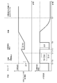
- 9 is a graph illustrating the change over time in the output voltage of a DCDC converter and the charging current supplied to a power storage unit in a conventional onboard power supply system.
- the internal resistance detection device 30 functions to detect the internal resistance of the power storage unit 21.
- the internal resistance detection device 30 includes a DC-DC converter 31 (hereinafter, also referred to as a DC-DC converter 31) mounted on a vehicle, a current detection unit 32, a voltage detection unit 33, and a control unit 34.
- the DCDC converter 31 corresponds to an example of a charging circuit unit, and is configured as a known DCDC converter.
- the DCDC converter 31 is provided on the conductive path 22.
- the DCDC converter 31 uses one of the conductive path 22A and the conductive path 22B as an input-side conductive path, the other as an output-side conductive path, and steps up or down the DC voltage applied to the input-side conductive path to output-side conductive path.
- the DCDC converter 31 functions to convert the power from the power supply unit 11 and supply a charging current to the power storage unit 21. Specifically, the DCDC converter 31 performs the constant current operation of outputting the charging current at the target charging current, thereby increasing the output voltage to the target voltage. When the output voltage reaches the target voltage, the DCDC converter 31 reduces the output voltage. In this configuration, power is controlled so as to decrease the charging current by performing a constant voltage operation that fixes the target voltage.
- the current detection unit 32 is configured as a known current detection circuit.
- the current detection unit 32 is a current detection circuit that detects a current flowing through the conductive path 22B (a charging current supplied to the power storage unit 21).
- a shunt resistor provided in the conductive path 22B and a voltage across the shunt resistor are provided.
- a differential amplifier for amplifying and outputting the amplified signal.
- the control unit 34 specifies the value of the current flowing through the conductive path 22B based on the value input from the current detection unit 32 (the detection value of the current detection unit 32), and specifies the value input from the current detection unit 32 (current detection The value of the current flowing through the conductive path 22B is specified based on the value detected by the unit 32).
- the voltage detector 33 functions to detect the output voltage of the DCDC converter 31.
- the voltage detection unit 33 is configured as a known voltage detection circuit.
- the voltage detection unit 33 is provided on the conductive path 22B and detects a voltage applied to the conductive path 22B.
- the voltage detection unit 33 inputs a value indicating the voltage of the conductive path 22B (for example, a voltage value of the conductive path 22B or a value obtained by dividing the voltage value of the conductive path 22B by a voltage dividing circuit) to the control unit 34 as a detection value. I do.
- the control unit 34 can specify the voltage value of the conductive path 22B based on the value input from the voltage detection unit 33 (the detection value of the voltage detection unit 33).
- the control unit 34 controls the operation of the DCDC converter 31 and the like.
- the control unit 34 is configured as, for example, a microcomputer, and includes an arithmetic device such as a CPU, a memory such as a ROM or a RAM, and the like.
- the control unit 34 operates using the power supplied from the power supply unit 11 or the power storage unit 21. Specifically, the control unit 34 causes the DCDC converter 31 to perform a constant current operation of outputting the charging current at the target charging current, thereby increasing the output voltage to the target voltage and causing the output voltage to reach the target voltage. Then, by causing the DCDC converter 31 to perform a constant voltage operation of fixing the output voltage to the target voltage, the power is controlled so as to decrease the charging current.
- the control unit 34 functions as a capacitance detection unit 34A and an internal resistance detection unit 34B.
- the capacitance detection unit 34A and the internal resistance detection unit 34B may be realized by software processing using an information processing device, or may be realized by a hardware circuit.
- Capacity detection unit 34A detects the capacity of power storage unit 21. Specifically, the capacitance detection unit 34A detects a change in the output voltage detected by the voltage detection unit 33 due to the elapse of a predetermined capacitance detection time when the DCDC converter 31 is performing the constant current operation, and the capacitance detection time. The capacity of power storage unit 21 is detected based on the charging current detected by current detection unit 32 during the passage of time.
- the internal resistance detection unit 34B includes a target charging current at the time of the constant current operation of the DCDC converter 31, a falling time that is an elapsed time from the start of the constant voltage operation to the time when the charging current falls to a predetermined current value, and a capacity.
- the internal resistance of power storage unit 21 is detected based on the capacity of power storage unit 21 detected by detection unit 34A.
- the control unit 34 changes from the sleep state to the activation state in response to establishment of a predetermined charging condition, and causes the DCDC converter 31 to perform a constant current operation (a constant current operation of outputting a charging current as a target charging current).
- the “establishment of the predetermined charging condition” is, for example, “the start switch (ignition switch or the like) of the vehicle has been switched from the off state to the on state”.
- the switch 14 is also switched from the off state to the on state in conjunction with each other, so that power is supplied from the power supply unit 11 to the load 12 and the power storage unit 21.
- the output voltage of the DCDC converter 31 before the constant current operation is lower than the target voltage, and the voltage detection unit 33 detects a value corresponding to the charging voltage of the power storage unit 21. Further, the charging current of the DCDC converter 31 before the constant current operation is lower than the target charging current. As shown in FIG. 2, when a predetermined charging condition is satisfied at time T1 and the constant current operation of the DCDC converter 31 is started, the DCDC converter 31 performs a constant current operation of outputting at the target charging current Ichg. Then, the output voltage is increased to the target voltage.
- control unit 34 performs detection control of the capacity of power storage unit 21 between time T1 and time T4. Specifically, the control unit 34 determines the change in the output voltage of the DCDC converter 31 during the time (predetermined capacity detection time ⁇ t1) from time T2 (when a short time has elapsed from time T1) to time T3, and The capacity C of the power storage unit 21 is detected based on the charging current supplied to the power storage unit 21.
- the charging current remains at Ichg (specified charging current) while the capacity detection time ⁇ t1 has elapsed, and the charge amount Q stored in the power storage unit 21 after the capacity detection time ⁇ t1 has elapsed is determined by subtracting the charging current Ichg from time T2 to time T3. Is calculated by integrating over the range of Since the output voltage that has increased after the passage of the capacitance detection time ⁇ t1 is ⁇ V, the capacitance C of the power storage unit 21 is calculated by dividing Q by ⁇ V.
- the predetermined current value is a current value lower than the target charging current, and is, for example, a preset current value stored in a memory or the like.
- control unit 34 calculates internal resistance R of power storage unit 21 based on target charging current Ichg, fall time ⁇ t2, and capacity C of power storage unit 21 calculated during the constant current operation.
- the internal resistance R is calculated based on the fall time ⁇ t2 and the capacity C of the power storage unit 21 calculated during the constant current operation. As described above, by measuring the falling time ⁇ t2 at which the predetermined current value I is detected in advance, the internal resistance R can be calculated with high accuracy from the above-described equation (I).
- the detection process of the internal resistance is performed before the output voltage of the DCDC converter 31 reaches the target voltage, so that the constant current operation of the power storage unit is interrupted, and The voltage will drop. Therefore, the time required for the output voltage to reach the target voltage becomes longer by the time the internal resistance detection process is performed.
- the internal resistance detection processing (calculation processing using a formula representing the predetermined current value I) while performing the constant voltage operation. Is performed. Therefore, the internal resistance of power storage unit 21 can be detected using the time of the constant voltage operation performed by DCDC converter 31.
- the control unit 34 is configured to detect the capacity of the power storage unit 21 during the constant resistance operation before the DC / DC converter 31 performs the constant voltage operation in the internal resistance detection processing. Therefore, high-accuracy capacitance detection that reflects the state (such as temperature characteristics) of power storage unit 21 immediately before the detection of the internal resistance can be performed. By using a capacitance that is accurately detected, the internal resistance of power storage unit 21 can be detected with higher accuracy.
- the control unit 34 controls the target charging current Ichg at the time of the constant current operation by the DCDC converter 31 and the time from the start of the constant voltage operation to the time when the charging current decreases to the predetermined current value.
- the configuration is such that the internal resistance R of the power storage unit 21 is detected based on the fall time ⁇ t2, which is the time, and the capacity C of the power storage unit.
- the target charging current Ichg at the time of the constant current operation by the DCDC converter 31, the fall time ⁇ t2 which is the elapsed time from the start of the constant voltage operation to the time when the charging current falls to the predetermined current value, and the capacity of the power storage unit C, the internal resistance R of the power storage unit 21 can be accurately detected.
- the control unit 34 detects the internal resistance R of the power storage unit 21 based on the current detected after the constant voltage operation is started by the DCDC converter 31 and the fall time ⁇ t2. Using the operation time, the internal resistance R of the power storage unit 21 can be detected.
- the control unit 34 detects the current charging unit 32 when the falling time has elapsed.
- I Ichg, which is an expression of a current detected by the current detection unit 32 when the fall time ⁇ t2 has elapsed since the DCDC converter 31 started constant voltage operation.
- the internal resistance detection device 30 has a configuration including a voltage detection unit 33 that detects an output voltage of the DCDC converter 31.
- the internal resistance detection device 30 detects a change in the output voltage detected by the voltage detection unit 33 due to the elapse of a predetermined capacitance detection time when the DCDC converter 31 is performing the constant current operation, and a time period during which the capacitance detection time elapses.
- the configuration includes a control unit 34 that detects the capacity of the power storage unit 21 based on the charging current detected by the current detection unit 32.
- Control unit 34 detects internal resistance R of power storage unit 21 based on target charging current Ichg, fall time ⁇ t2, and calculated capacity C of power storage unit 21.
- the control unit 34 when detecting the internal resistance R, uses the capacity of the power storage unit 21 calculated during the constant current operation of the DCDC converter 31.
- the capacity may be used, or a value of the capacity set in advance and stored in a memory or the like may be used.
- the switching of the start switch (ignition switch or the like) of the vehicle from the off state to the on state is defined as “satisfaction of a predetermined charging start condition”.
- the fact that the charge voltage has dropped to or below the charging voltage may be regarded as “establishment of a predetermined charging start condition”.
- the switch 14 is a switch that performs an on / off operation in conjunction with a vehicle start switch, but may be a vehicle start switch (an ignition switch or the like) itself.
- control unit 34 performs control to detect the capacity of the power storage unit 21 in a state where a charging current having a constant current value is supplied to the power storage unit 21 during the charging operation by the DCDC converter 31.
- a configuration in which a charging current having a non-constant current value is supplied during the capacity detection control of the power storage unit 21 may be employed. Even with such a configuration, the charge amount Q stored in the power storage unit 21 is calculated by integrating the charging current over a predetermined time range.
Abstract
L'invention concerne une configuration permettant de détecter efficacement et avec précision la résistance interne d'une unité de stockage d'énergie. Ledit dispositif de détection de résistance interne (30) effectue une commande de puissance électrique de telle sorte qu'un convertisseur CC/CC (31) effectue une opération à courant constant dans laquelle un courant de charge est émis à un courant de charge cible, ce qui permet d'augmenter une tension de sortie jusqu'à une tension cible, et lorsque la tension de sortie atteint la tension cible, effectue une opération à tension constante dans laquelle la tension de sortie est fixée sur la tension cible, ce qui permet de réduire le courant de charge. Une unité de commande (34) détecte la résistance interne R d'une unité de stockage d'énergie (21) en fonction : d'un courant de charge cible Ichg pendant l'opération à courant constant effectuée par le convertisseur CC/CC (31); d'un temps de chute Δt2 constituant un temps écoulé depuis un instant de démarrage de l'opération de tension constante jusqu'à un instant où le courant de charge chute à une valeur de courant prédéterminée; et de la capacité C de l'unité de stockage d'énergie (21).
Priority Applications (2)
| Application Number | Priority Date | Filing Date | Title |
|---|---|---|---|
| CN201980051866.6A CN112513652A (zh) | 2018-08-22 | 2019-08-01 | 内部电阻检测装置及电源装置 |
| US17/266,359 US11843096B2 (en) | 2018-08-22 | 2019-08-01 | Internal resistance detection device and power source device |
Applications Claiming Priority (2)
| Application Number | Priority Date | Filing Date | Title |
|---|---|---|---|
| JP2018155223A JP7042413B2 (ja) | 2018-08-22 | 2018-08-22 | 内部抵抗検出装置及び電源装置 |
| JP2018-155223 | 2018-08-22 |
Publications (1)
| Publication Number | Publication Date |
|---|---|
| WO2020039881A1 true WO2020039881A1 (fr) | 2020-02-27 |
Family
ID=69593019
Family Applications (1)
| Application Number | Title | Priority Date | Filing Date |
|---|---|---|---|
| PCT/JP2019/030241 WO2020039881A1 (fr) | 2018-08-22 | 2019-08-01 | Dispositif de détection de résistance interne et dispositif d'alimentation électrique |
Country Status (4)
| Country | Link |
|---|---|
| US (1) | US11843096B2 (fr) |
| JP (1) | JP7042413B2 (fr) |
| CN (1) | CN112513652A (fr) |
| WO (1) | WO2020039881A1 (fr) |
Families Citing this family (2)
| Publication number | Priority date | Publication date | Assignee | Title |
|---|---|---|---|---|
| KR20210099504A (ko) * | 2020-02-04 | 2021-08-12 | 삼성전자주식회사 | 배터리 시스템에서 배터리의 작동 상태를 검출하는 방법 및 시스템 |
| WO2021257593A1 (fr) * | 2020-06-16 | 2021-12-23 | Black & Decker Inc. | Chargeur de batterie |
Citations (5)
| Publication number | Priority date | Publication date | Assignee | Title |
|---|---|---|---|---|
| JPH08136629A (ja) * | 1994-11-11 | 1996-05-31 | Kyushu Electric Power Co Inc | 蓄電池寿命診断装置 |
| JP2011043460A (ja) * | 2009-08-24 | 2011-03-03 | Sanyo Electric Co Ltd | 二次電池の特性検出方法および二次電池装置 |
| JP2012202687A (ja) * | 2011-03-23 | 2012-10-22 | Tamura Seisakusho Co Ltd | 電気二重層キャパシタの状態観測装置 |
| JP2012247339A (ja) * | 2011-05-30 | 2012-12-13 | Renesas Electronics Corp | 半導体集積回路およびその動作方法 |
| JP2018068081A (ja) * | 2016-10-21 | 2018-04-26 | 京セラ株式会社 | 二次電池の充電時間の予測装置および予測方法 |
Family Cites Families (10)
| Publication number | Priority date | Publication date | Assignee | Title |
|---|---|---|---|---|
| TW535308B (en) * | 2000-05-23 | 2003-06-01 | Canon Kk | Detecting method for detecting internal state of a rechargeable battery, detecting device for practicing said detecting method, and instrument provided with said |
| US6683440B2 (en) * | 2001-05-29 | 2004-01-27 | Canon Kabushiki Kaisha | Detecting method for detecting internal information of a rechargeable battery, detecting apparatus for detecting internal information of a rechargeable battery, apparatus in which said detecting method is applied, apparatus including said detecting apparatus, and storage medium in which a software program of said detecting method is stored |
| JP2008064700A (ja) | 2006-09-11 | 2008-03-21 | Matsushita Electric Ind Co Ltd | 電気二重層キャパシタの内部抵抗測定装置 |
| JP4499810B2 (ja) * | 2008-05-28 | 2010-07-07 | 株式会社日本自動車部品総合研究所 | 車載バッテリの状態推定装置 |
| JP6119402B2 (ja) * | 2012-05-29 | 2017-04-26 | 株式会社Gsユアサ | 内部抵抗推定装置及び内部抵抗推定方法 |
| JP2014102248A (ja) * | 2012-10-24 | 2014-06-05 | Gs Yuasa Corp | 蓄電状態検出装置 |
| JP5984700B2 (ja) * | 2013-01-31 | 2016-09-06 | 新電元工業株式会社 | 直流電源装置、蓄電池の充電方法及び直流電源装置の監視制御装置 |
| WO2014162907A1 (fr) * | 2013-04-03 | 2014-10-09 | 株式会社オートネットワーク技術研究所 | Dispositif de commande, dispositif de commande d'alimentation électrique, procédé de commande de charge, dispositif de commande de charge et dispositif d'alimentation électrique pour un véhicule |
| CN104020353A (zh) * | 2014-03-12 | 2014-09-03 | 宁波南车新能源科技有限公司 | 超级电容器内阻测定方法 |
| JP6365497B2 (ja) * | 2015-10-14 | 2018-08-01 | 株式会社オートネットワーク技術研究所 | 電流制御装置、電流制御方法及びコンピュータプログラム |
-
2018
- 2018-08-22 JP JP2018155223A patent/JP7042413B2/ja active Active
-
2019
- 2019-08-01 CN CN201980051866.6A patent/CN112513652A/zh active Pending
- 2019-08-01 WO PCT/JP2019/030241 patent/WO2020039881A1/fr active Application Filing
- 2019-08-01 US US17/266,359 patent/US11843096B2/en active Active
Patent Citations (5)
| Publication number | Priority date | Publication date | Assignee | Title |
|---|---|---|---|---|
| JPH08136629A (ja) * | 1994-11-11 | 1996-05-31 | Kyushu Electric Power Co Inc | 蓄電池寿命診断装置 |
| JP2011043460A (ja) * | 2009-08-24 | 2011-03-03 | Sanyo Electric Co Ltd | 二次電池の特性検出方法および二次電池装置 |
| JP2012202687A (ja) * | 2011-03-23 | 2012-10-22 | Tamura Seisakusho Co Ltd | 電気二重層キャパシタの状態観測装置 |
| JP2012247339A (ja) * | 2011-05-30 | 2012-12-13 | Renesas Electronics Corp | 半導体集積回路およびその動作方法 |
| JP2018068081A (ja) * | 2016-10-21 | 2018-04-26 | 京セラ株式会社 | 二次電池の充電時間の予測装置および予測方法 |
Also Published As
| Publication number | Publication date |
|---|---|
| US20210311100A1 (en) | 2021-10-07 |
| JP7042413B2 (ja) | 2022-03-28 |
| CN112513652A (zh) | 2021-03-16 |
| US11843096B2 (en) | 2023-12-12 |
| JP2020030085A (ja) | 2020-02-27 |
Similar Documents
| Publication | Publication Date | Title |
|---|---|---|
| JP4807058B2 (ja) | 車両用電源装置 | |
| JP6698599B2 (ja) | 地絡検出装置 | |
| US10139453B2 (en) | Battery voltage monitoring device using capacitor circuit and switch failure detection circuit | |
| JP2009122056A (ja) | バッテリ充放電電流検出装置 | |
| US20070030016A1 (en) | Device and method for monitoring at least one energy reserve capacitor in a restraint system | |
| JP2013179760A (ja) | 電源装置 | |
| WO2011001649A1 (fr) | Dispositif d'alimentation en énergie électrique | |
| JP2014038023A (ja) | 地絡検出回路、電源装置 | |
| JP7039541B2 (ja) | 地絡検出装置 | |
| US10663506B2 (en) | System for diagnosing fault of relays for vehicle | |
| JP2000324702A (ja) | バッテリの放電容量検出方法及びその装置並びに車両用バッテリ制御装置 | |
| WO2018180333A1 (fr) | Dispositif de commande pour système d'alimentation électrique embarqué, et système d'alimentation électrique embarqué | |
| WO2020039881A1 (fr) | Dispositif de détection de résistance interne et dispositif d'alimentation électrique | |
| JP5251943B2 (ja) | バッテリ充放電電流検出装置 | |
| JP2015014563A (ja) | 電池状態検出装置 | |
| CN109804524B (zh) | 车辆用备用装置 | |
| JP5298773B2 (ja) | 蓄電装置 | |
| JP2010124582A (ja) | 蓄電装置 | |
| JPWO2018230187A1 (ja) | 電池監視装置 | |
| JP2006010501A (ja) | バッテリ状態管理装置 | |
| JP4670301B2 (ja) | バックアップ電源システム | |
| JP2005253154A (ja) | 電源装置 | |
| JP2010188851A (ja) | 車両用電源装置 | |
| JP6607161B2 (ja) | 車載電池システムの制御方法 | |
| JP2010261807A (ja) | 蓄電池の劣化判定方法、充放電制御装置 |
Legal Events
| Date | Code | Title | Description |
|---|---|---|---|
| 121 | Ep: the epo has been informed by wipo that ep was designated in this application |
Ref document number: 19851509 Country of ref document: EP Kind code of ref document: A1 |
|
| NENP | Non-entry into the national phase |
Ref country code: DE |
|
| 122 | Ep: pct application non-entry in european phase |
Ref document number: 19851509 Country of ref document: EP Kind code of ref document: A1 |