WO2020039783A1 - 光源装置、プロジェクタ、及び照明装置 - Google Patents
光源装置、プロジェクタ、及び照明装置 Download PDFInfo
- Publication number
- WO2020039783A1 WO2020039783A1 PCT/JP2019/027398 JP2019027398W WO2020039783A1 WO 2020039783 A1 WO2020039783 A1 WO 2020039783A1 JP 2019027398 W JP2019027398 W JP 2019027398W WO 2020039783 A1 WO2020039783 A1 WO 2020039783A1
- Authority
- WO
- WIPO (PCT)
- Prior art keywords
- light source
- source device
- housing
- bolt
- optical path
- Prior art date
- Legal status (The legal status is an assumption and is not a legal conclusion. Google has not performed a legal analysis and makes no representation as to the accuracy of the status listed.)
- Ceased
Links
Images


Classifications
-
- G—PHYSICS
- G03—PHOTOGRAPHY; CINEMATOGRAPHY; ANALOGOUS TECHNIQUES USING WAVES OTHER THAN OPTICAL WAVES; ELECTROGRAPHY; HOLOGRAPHY
- G03B—APPARATUS OR ARRANGEMENTS FOR TAKING PHOTOGRAPHS OR FOR PROJECTING OR VIEWING THEM; APPARATUS OR ARRANGEMENTS EMPLOYING ANALOGOUS TECHNIQUES USING WAVES OTHER THAN OPTICAL WAVES; ACCESSORIES THEREFOR
- G03B21/00—Projectors or projection-type viewers; Accessories therefor
- G03B21/14—Details
- G03B21/20—Lamp housings
- G03B21/2066—Reflectors in illumination beam
-
- F—MECHANICAL ENGINEERING; LIGHTING; HEATING; WEAPONS; BLASTING
- F21—LIGHTING
- F21V—FUNCTIONAL FEATURES OR DETAILS OF LIGHTING DEVICES OR SYSTEMS THEREOF; STRUCTURAL COMBINATIONS OF LIGHTING DEVICES WITH OTHER ARTICLES, NOT OTHERWISE PROVIDED FOR
- F21V14/00—Controlling the distribution of the light emitted by adjustment of elements
- F21V14/06—Controlling the distribution of the light emitted by adjustment of elements by movement of refractors
-
- F—MECHANICAL ENGINEERING; LIGHTING; HEATING; WEAPONS; BLASTING
- F21—LIGHTING
- F21V—FUNCTIONAL FEATURES OR DETAILS OF LIGHTING DEVICES OR SYSTEMS THEREOF; STRUCTURAL COMBINATIONS OF LIGHTING DEVICES WITH OTHER ARTICLES, NOT OTHERWISE PROVIDED FOR
- F21V9/00—Elements for modifying spectral properties, polarisation or intensity of the light emitted, e.g. filters
- F21V9/30—Elements containing photoluminescent material distinct from or spaced from the light source
- F21V9/32—Elements containing photoluminescent material distinct from or spaced from the light source characterised by the arrangement of the photoluminescent material
-
- G—PHYSICS
- G02—OPTICS
- G02B—OPTICAL ELEMENTS, SYSTEMS OR APPARATUS
- G02B19/00—Condensers, e.g. light collectors or similar non-imaging optics
- G02B19/0004—Condensers, e.g. light collectors or similar non-imaging optics characterised by the optical means employed
- G02B19/0009—Condensers, e.g. light collectors or similar non-imaging optics characterised by the optical means employed having refractive surfaces only
- G02B19/0014—Condensers, e.g. light collectors or similar non-imaging optics characterised by the optical means employed having refractive surfaces only at least one surface having optical power
-
- G—PHYSICS
- G02—OPTICS
- G02B—OPTICAL ELEMENTS, SYSTEMS OR APPARATUS
- G02B7/00—Mountings, adjusting means, or light-tight connections, for optical elements
- G02B7/02—Mountings, adjusting means, or light-tight connections, for optical elements for lenses
- G02B7/04—Mountings, adjusting means, or light-tight connections, for optical elements for lenses with mechanism for focusing or varying magnification
-
- G—PHYSICS
- G03—PHOTOGRAPHY; CINEMATOGRAPHY; ANALOGOUS TECHNIQUES USING WAVES OTHER THAN OPTICAL WAVES; ELECTROGRAPHY; HOLOGRAPHY
- G03B—APPARATUS OR ARRANGEMENTS FOR TAKING PHOTOGRAPHS OR FOR PROJECTING OR VIEWING THEM; APPARATUS OR ARRANGEMENTS EMPLOYING ANALOGOUS TECHNIQUES USING WAVES OTHER THAN OPTICAL WAVES; ACCESSORIES THEREFOR
- G03B21/00—Projectors or projection-type viewers; Accessories therefor
- G03B21/14—Details
- G03B21/20—Lamp housings
- G03B21/2006—Lamp housings characterised by the light source
- G03B21/2033—LED or laser light sources
- G03B21/204—LED or laser light sources using secondary light emission, e.g. luminescence or fluorescence
-
- G—PHYSICS
- G03—PHOTOGRAPHY; CINEMATOGRAPHY; ANALOGOUS TECHNIQUES USING WAVES OTHER THAN OPTICAL WAVES; ELECTROGRAPHY; HOLOGRAPHY
- G03B—APPARATUS OR ARRANGEMENTS FOR TAKING PHOTOGRAPHS OR FOR PROJECTING OR VIEWING THEM; APPARATUS OR ARRANGEMENTS EMPLOYING ANALOGOUS TECHNIQUES USING WAVES OTHER THAN OPTICAL WAVES; ACCESSORIES THEREFOR
- G03B21/00—Projectors or projection-type viewers; Accessories therefor
- G03B21/14—Details
- G03B21/20—Lamp housings
- G03B21/208—Homogenising, shaping of the illumination light
Definitions
- the present invention relates to a light source device, and a projector and a lighting device using the same.
- Patent Document 1 discloses that “a light source device has a wavelength conversion member including a substrate rotatable around a predetermined rotation axis, and a phosphor layer provided on the substrate including a phosphor.
- a “comprising (summary excerpt)” configuration is disclosed.
- the excitation light may not be appropriately focused on the phosphor layer due to a dimensional error or a mounting error of the component.
- the excitation light is not collected on the phosphor layer, there is a problem that the amount of light output from the fluorescent device is reduced.
- the wavelength conversion member and the condensing optical system are arranged at extremely close positions so that the visible light converted by the phosphor layer is allowed to enter the condensing optical system without leakage. A slight shift in the distance between the conversion member and the condensing optical system causes a large decrease in the amount of light. Note that this problem can occur not only between the wavelength conversion member and the condensing optical system, but also in another optical system including a lens that refracts the excitation light and a reflection member that reflects the excitation light that has passed through the lens. .
- An advantage of some aspects of the invention is to provide a light source device, a projector, and a lighting device each having a simple structure and a mechanism capable of adjusting an optical path length between a reflecting member and a lens. With the goal.
- the present invention has the configuration described in the claims.
- the present invention provides an excitation light source that generates excitation light, a reflection member that reflects the excitation light, and an excitation light source that is disposed on an optical path of the excitation light from the excitation light source to the reflection member.
- An operating member and an adjusting mechanism that adjusts an optical path length between the reflecting member and the lens in conjunction with the operating member that protrudes and retracts from the housing are provided.
- a light source device a projector, and a lighting device each having a simple structure and having a mechanism capable of adjusting an optical path length between a reflecting member and a lens.
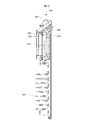
- Exploded perspective view of a projector External view of component parts of projector External view of optical engine Exploded perspective view of the optical engine Diagram showing the internal structure of the optical engine Exploded perspective view of a first housing part, an adjustment mechanism, and an operation member Front view of the first housing part on the side where the protrusion is provided.
- Perspective view of the side where the concave portion of the rotating ring is provided The figure which shows the positional relationship of a bolt, a transmission member, and a rotating ring.
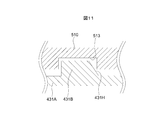
- Sectional view at XX in FIG. Diagram showing a state in which a concave portion receives a convex portion
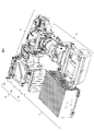
- FIGS. 1 is an exploded perspective view of the projector 1
- FIG. 2 is an external view of components of the projector 1
- FIG. 3 is an outline view of the optical engine 4
- FIG. 4 is an exploded perspective view of the optical engine 4.
- FIG. 5 is a diagram showing the internal structure of the optical engine 4.
- the projector 1 is configured such that each component of the projector 1 is accommodated in a box-shaped bottom case 2 and an upper case 9 is put on the bottom case 2.
- a heat pipe 3, an optical engine 4 provided adjacent to the heat pipe 3, and video light including video information displayed on a panel using the light emitted from the optical engine 4 are emitted to the bottom case 2.
- a panel optical system 5 and a projection optical system 6 including an optical element (lens unit and concave mirror) for enlarging and projecting image light are accommodated.
- the upper part of the heat pipe 3 is covered with a duct cover 8 in which a cooling duct 7 is formed.
- the optical engine 4 is installed side by side in a state where the laser module housing 41, the color synthesizing unit 42, and the phosphor wheel housing 43 are optically connected.
- the optical engine 4 corresponds to a light source device.
- the laser module housing 41 mainly includes a laser light source 411 and a collimating lens 412.
- the laser light source 411 includes at least one solid-state light emitting element such as a laser light emitting element, and emits, for example, blue laser light as the excitation light 414.
- the laser light source 411 corresponds to an excitation light source. Excitation light 414 (shown by a solid line) emitted from the laser light source 411 is converted into substantially parallel light by the collimator lens 412 and enters the color synthesizing unit 42.
- the surface of the laser module housing 41 opposite to the color synthesizing unit 42 faces the heat pipe 3. Then, the heat generated from the laser light source 411 is transmitted to the wall of the laser module housing 41 and is emitted to the outside of the laser module housing 41, and is cooled by the heat pipe 3.
- the color synthesizing unit 42 mainly includes a dichroic mirror 421, a condenser lens 422, and a diffusion plate 423.
- the dichroic mirror 421 reflects and transmits the excitation light 414 and reflects the fluorescent light (yellow).
- the condenser lens 422 is disposed on the optical path of the excitation light 414 from the laser light source 411 to the diffusion plate 423.
- the condenser lens 422 corresponds to a lens that refracts (collects) the excitation light 414, and the diffusion plate 423 corresponds to a reflection member.
- Part of the excitation light 414 is reflected by the dichroic mirror 421, condensed by the condenser lens 422, and enters the diffusion plate 423.
- the excitation light 414 incident on the diffusion plate 423 is diffused and reflected by the diffusion plate 423, passes through the condenser lens 422 and the dichroic mirror 421, and is emitted to the panel optical system 5. Further, another part of the excitation light 414 incident from the laser light source 411 passes through the dichroic mirror 421 and is emitted to the phosphor wheel housing 43.
- the phosphor wheel housing 43 includes a first housing part 431 facing the color combining unit 42 and a second housing part 432 located on the side opposite to the color combining unit 42.
- the first housing part 431 and the second housing part 432 are joined via a rubber packing (not shown) on the peripheral edge, and the internal space is sealed.
- the phosphor wheel housing 43 corresponds to a housing.
- the first housing part 431 and the second housing part 432 correspond to a first housing and a second housing that form an internal space by closely adhering their peripheral edges.
- a lens hole 434 into which the condenser lens 433 is inserted is formed in the first housing part 431.
- the first housing part 431 supports the condenser lens 433 (FIG. 5) inserted into the lens hole 434, an adjustment mechanism 500 described later, and an operation member 560 described later.
- the condenser lens 433 is arranged on the optical path of the excitation light 414 from the laser light source 411 to the phosphor wheel 435.
- the condenser lens 433 (FIG. 5) corresponds to a lens that refracts (condenses) the excitation light 414.
- Fins 432A are formed on the outer surface of the second housing part 432. Thereby, the internal space of the phosphor wheel housing 43 is cooled.
- the phosphor wheel 435, the motor board 436, and the wheel motor 437 are mainly housed in the sealed inner space of the phosphor wheel housing 43.
- the phosphor wheel 435 includes a substrate 438 (FIG. 5), and a phosphor layer 439 (FIG. 5) laminated on a surface (front surface) of the substrate 438 on the side facing the condenser lens 433 (FIG. 5).
- the phosphor wheel 435 corresponds to a reflection member and a wavelength conversion member.
- the phosphor layer 439 (FIG. 5) includes a functional film that converts the incident excitation light 414 into fluorescent light and reflects it.
- the material of the functional film is not particularly limited.
- the functional film may be composed of a sintered phase containing phosphor particles and aluminum oxide (alumina) and an air phase.
- the phosphor particles are YAG or LAG.
- the motor board 436 drives the wheel motor 437 under the control of a controller (not shown) provided in the projector 1.
- the wheel motor 437 rotates the phosphor wheel 435.
- the excitation light 414 emitted from the color synthesizing unit 42 is condensed by the condensing lens 433 and is converted into fluorescent light by the phosphor wheel 435. Then, the fluorescent light converted by the phosphor wheel 435 passes through the condenser lens 433, is reflected by the dichroic mirror 421, and is emitted to the panel optical system 5 (FIG. 1). Therefore, the light emitted from the optical engine 4 becomes white light 440 in which the excitation light 414 diffused and reflected by the diffusion plate 423 and the fluorescent light reflected by the phosphor wheel 435 are mixed.
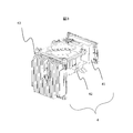
- FIG. 6 is an exploded perspective view of the first housing part 431, the adjusting mechanism 500, and the operating member 560.
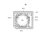
- FIG. 7 is a front view of the first housing part 431 on the side where the protrusions 431B to 431D are provided.
- 8 is a perspective view of the rotary ring 510 on the side where the concave portions 513 to 515 are provided
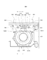
- FIG. 9 is a view showing the positional relationship among the bolts 561 and 562, the transmission members 541 and 542, and the rotary ring 510.
- FIG. 11 is a cross-sectional view taken along line XX of FIG. 9, FIG. 11 is a diagram showing a state in which the concave portion 513 has received the convex portion 431B, and FIG. It is.
- the adjusting mechanism 500 mainly includes a rotating ring 510, a coil spring 520, a pressing member 530, transmission members 541 and 542, and a torsion coil spring 550.
- the operation member 560 mainly includes bolts 561 and 562.
- the adjustment mechanism 500 moves the condenser lens 433 along the optical path of the excitation light 414 in conjunction with the movement of the operation member 560 manually operated by the operator. Thus, the optical path length between the condenser lens 433 and the phosphor wheel 435 is adjusted.
- the first housing part 431 has a ring portion 431A at a position surrounding the lens hole 434.
- the ring portion 431A has a C-shaped outer shape whose upper part is open.
- convex portions 431B, 431C, and 431D are formed on the wall surface of the ring portion 431A on the side in contact with the rotating ring 510.
- the protrusions 431B to 431D are arranged at predetermined intervals (in this embodiment, at 120 ° intervals) in the circumferential direction.
- a slit 431E is formed in an open portion of the ring portion 431A (that is, at an upper end of the lens hole 434).
- the first housing part 431 is formed with bolt holes 431F, 431G (FIG. 6) penetrating in a direction intersecting (perpendicular to) the optical path of the excitation light 414 (FIG. 5).
- One end of each of the bolt holes 431F and 431G is exposed to the outside of the first housing part 431, and the other end is located near the slit 431E.
- the rotating ring 510 has a ring-shaped outer shape with a through hole 511 formed in the center.
- One wall surface in the thickness direction of the rotating ring 510 abuts on the ring portion 431A of the first housing part 431.
- the wall surface on the other side in the thickness direction of the rotating ring 510 abuts on the condenser lens 433.
- the rotating ring 510 corresponds to a rotating member.
- Rotating ring 510 includes protrusion 512.
- the protrusion 512 protrudes radially outward from one location of the outer edge of the rotating ring 510.
- concave portions 513, 514, and 515 are formed on the wall surface of the rotating ring 510 on the side in contact with the ring portion 431A.
- the concave portions 513 to 515 have positions and sizes that can receive the convex portions 431B to 431D formed on the ring portion 431A.
- a concave portion may be formed in the first housing part 431, and a convex portion may be formed in the rotating ring 510. That is, it is only necessary that one of the wall surfaces of the first housing part 431 and the rotating ring 510 that is in contact with each other has a convex portion and the other has a concave portion.
- the through hole 511 communicates with the lens hole 434, and the projection 512 is exposed on the surface on the opposite side of the first housing part 431 through the slit 431E.
- 513 to 515 receive the corresponding convex portions 431B to 431D.
- the rotating ring 510 is a rotatable in the axial line L 1 around which extends in the direction of the optical path of the excitation light 414 is supported by the first housing part 431.
- the coil spring 520 is disposed on the opposite side of the rotating ring 510 with the condenser lens 433 interposed therebetween.
- the pressing member 530 is fixed to the first housing part 431 by bolts 531, 532, 533.
- the pressing member 530 presses the rotating ring 510, the condenser lens 433, and the coil spring 520 against the first housing part 431 from outside the coil spring 520.
- the coil spring 520 urges the rotating ring 510 and the condenser lens 433 in a direction of pressing the first housing part 431 (in other words, a direction of approaching the phosphor wheel 435).
- the transmission members 541 and 542 are disposed on the opposite side of the rotation ring 510 with the first housing part 431 interposed therebetween.
- the transmission members 541 and 542 are arranged so as to sandwich the projection 512 exposed through the slit 431E in the circumferential direction.
- the transmission members 541 and 542 are supported by the first housing part 431 by bolts 543 and 544 in a state where the transmission members 541 and 542 are rotatable around axes L 2 and L 3 extending in the direction of the optical path of the excitation light 414.
- the transmission member 541 corresponds to a first transmission member
- the transmission member 542 corresponds to a second transmission member.
- the transmission members 541 and 542 have first contact portions 541A and 542A and second contact portions 541B and 542B.
- the first contact portions 541A and 542A are provided at positions where they can contact the bolts 561 and 562 screwed into the bolt holes 431F and 431G.
- the second contact portions 541B and 542B are provided at positions where they can contact the protrusions 512 of the rotating ring 510.
- the transmission members 541 and 542 convert the linear motion of the bolts 561 and 562 into rotary motion and transmit the rotary motion to the rotary ring 510. The movement of the transmission members 541 and 542 will be described later.
- the torsion coil spring 550 is fixed to the first housing part 431 by the bolt 551 with one end abutting on the first housing part 431 and the other end abutting on the rotating ring 510.
- the torsion coil spring 550 urges the rotating ring 510 in a direction to press the projection 512 against the transmission member 541.
- the coil spring 520 corresponds to a first urging member
- the torsion coil spring 550 corresponds to a second urging member.
- specific examples of the first urging member and the second urging member are not limited to these, and a leaf spring, elastic rubber, or the like may be employed.
- the bolts 561 and 562 are linearly moved in a direction of immersing in the first housing part 431 and a direction of protruding from the first housing part 431 by being twisted while being screwed into the bolt holes 431F and 431G.
- Bolts 561 and 562 to move in a direction retracts the first housing part 431, the first contact portion 541A, in contact with the 542A, rotates the transmission member 541 and 542 in the axis L 2, L 3 around.
- Nuts 563 and 564 are screwed to the bolts 561 and 562 on the opposite sides of the transmission members 541 and 542 with the bolt holes 431F and 431G interposed therebetween.
- the bolt 561 corresponds to a first bolt
- the bolt 562 corresponds to a second bolt
- the nuts 563 and 564 correspond to fixing members.
- the second contact portion 541B of the transmission member 541 contacts the projection 512, and the second contact member 542B of the transmission member 542 is separated from the projection 512.
- the concave portions 513, 514, 515 (514, 515 are not shown) have received the corresponding convex portions 431B, 431C, 431D (431C, 431D are not shown). Further, the following operations are performed, for example, in a state where the power of the projector 1 is turned on and an image is displayed on a screen.
- the degree of condensing the excitation light 414 on the phosphor wheel 435 changes.
- the brightness of the image displayed on the screen by the projector 1 changes. Therefore, the operator adjusts the bolt 561 to a position where an image having a desired brightness (typically, the brightest image) is displayed. Then, in order to fix the bolt 561 at a position where an image of a desired brightness is obtained, the worker screwes the nut 563 into contact with the first housing part 431.
- the operator twists the bolt 562 in a direction to be immersed in the first housing part 431. Accordingly, the bolt 562 contacts the first contact portion 542A of the transmission member 542, and rotates the transmission member 542 counterclockwise in FIG. Then, the worker turns the nut 564 into contact with the first housing part 431 in order to fix the bolt 562 at a position where the second contact portion 542B of the transmission member 542 contacts the protrusion 512.
- the optical engine 4 includes a number of components (for example, a laser light source 411, a collimating lens 412, a dichroic mirror 421, a phosphor wheel 435, a fin 432A, etc.) along an optical path of the excitation light 414. ) Is arranged. Therefore, in order to expose the bolts 561 and 562 in a direction along the optical path of the excitation light 414, it is necessary to avoid these components and to dispose them. In addition, the distance from the adjusting mechanism 500 to the exposed position of the bolts 561 and 562 is required. Becomes longer.
- the adjusting mechanism 500 adjusts the optical path lengths of the condenser lens 433 and the phosphor wheel 435 in conjunction with the bolts 561 and 562 that appear and disappear by manual operation of an operator. As compared with the driving device, the adjusting mechanism 500 having a simple structure can be realized.
- the bolts 561 and 562 screwed into the bolt holes 431F and 431G are used as the operation members 560, so that the operation members 560 are exposed to the outside of the first housing parts 431. Regardless, the dustproof property required by the optical engine 4 can be ensured without attaching a packing or the like. Further, since the position of the condenser lens 433 is adjusted by twisting the bolts 561 and 562, fine adjustment of the optical path length becomes easy.
- the condensing lens 433 is moved away from the phosphor wheel 435 against the urging force of the coil spring 520 by causing the protrusions 431B, 431C, and 431D to ride on the recesses 513, 514, and 515. Move in the direction.
- the condenser lens 433 is constantly pressed from both sides of the optical path of the excitation light 414, it is possible to suppress the play of the condenser lens 433 in the direction of the optical path of the excitation light 414.
- the position of the condenser lens 433 is changed due to the rattling of the rotating ring 510 in the circumferential direction.
- the displacement along the optical path of the excitation light 414 can be suppressed.
- the transmission member 542 is brought into contact with the rotating ring 510 by operating the bolt 562.
- the rattling of the rotating ring 510 in the circumferential direction can be more effectively suppressed.
- the bolts 561 and 562 are fixed by the nuts 563 and 564, so that the bolts are unintentionally adjusted. It is possible to suppress deviation of the optical path length due to the operation of 561 and 562.
- specific examples of the fixing member are not limited to the nuts 563 and 564, and an adhesive filled in the bolt holes 431F and 431G may be used as the fixing member.
- the same first housing part 431 supports the condensing lens 433 to be moved and the adjusting mechanism 500 and the operating member 560 for moving the condensing lens 433.
- the effects of mounting errors can be minimized.
- a part of the condenser lens 433, the adjustment mechanism 500, and the operation member 560 may be supported by different housings.
- the middle of the moving range of the condenser lens 433 is set as an initial position, and the condenser lens 433 can be moved by the adjusting mechanism 500 both in a direction away from the phosphor wheel 435 and in a direction approaching the phosphor wheel 435. May be configured.
- the object that the adjustment mechanism 500 moves is not limited to the condenser lens 433.
- the adjustment mechanism 500 may move the phosphor wheel 435 along the direction of the optical path of the excitation light 414. That is, the adjustment mechanism 500 only needs to be able to adjust the optical path length between the condenser lens 433 and the phosphor wheel 435 by changing the relative distance between the condenser lens 433 and the phosphor wheel 435.
- the adjusting mechanism 500 may move the collimating lens 412 or another lens (not shown) instead of the condenser lens 433. That is, the lens targeted by the present invention is not limited to a lens that collects the excitation light 414, and may be a lens that collimates the excitation light 414 (another example of refraction).
- the adjustment target is not limited to the optical path length between the condenser lens 433 and the phosphor wheel 435.
- an adjustment mechanism and an operation member for changing the relative distance between the condenser lens 422 and the diffusion plate 423 may be provided.
- the projector 1 is described as an application example of the light source device according to the present invention.
Landscapes
- Physics & Mathematics (AREA)
- General Physics & Mathematics (AREA)
- Optics & Photonics (AREA)
- Engineering & Computer Science (AREA)
- Spectroscopy & Molecular Physics (AREA)
- General Engineering & Computer Science (AREA)
- Multimedia (AREA)
- Projection Apparatus (AREA)
- Non-Portable Lighting Devices Or Systems Thereof (AREA)
Priority Applications (2)
| Application Number | Priority Date | Filing Date | Title |
|---|---|---|---|
| CN201980055027.1A CN112585533A (zh) | 2018-08-22 | 2019-07-10 | 光源装置、投影仪和照明装置 |
| US17/269,765 US11307377B2 (en) | 2018-08-22 | 2019-07-10 | Light source device, projector and lighting device |
Applications Claiming Priority (2)
| Application Number | Priority Date | Filing Date | Title |
|---|---|---|---|
| JP2018155675A JP2020030314A (ja) | 2018-08-22 | 2018-08-22 | 光源装置、プロジェクタ、及び照明装置 |
| JP2018-155675 | 2018-08-22 |
Publications (1)
| Publication Number | Publication Date |
|---|---|
| WO2020039783A1 true WO2020039783A1 (ja) | 2020-02-27 |
Family
ID=69592508
Family Applications (1)
| Application Number | Title | Priority Date | Filing Date |
|---|---|---|---|
| PCT/JP2019/027398 Ceased WO2020039783A1 (ja) | 2018-08-22 | 2019-07-10 | 光源装置、プロジェクタ、及び照明装置 |
Country Status (4)
| Country | Link |
|---|---|
| US (1) | US11307377B2 (https=) |
| JP (1) | JP2020030314A (https=) |
| CN (1) | CN112585533A (https=) |
| WO (1) | WO2020039783A1 (https=) |
Cited By (1)
| Publication number | Priority date | Publication date | Assignee | Title |
|---|---|---|---|---|
| WO2024241462A1 (ja) * | 2023-05-23 | 2024-11-28 | シャープNecディスプレイソリューションズ株式会社 | 光源 |
Families Citing this family (3)
| Publication number | Priority date | Publication date | Assignee | Title |
|---|---|---|---|---|
| EP3835866A1 (en) * | 2019-12-10 | 2021-06-16 | Barco | A laser reflection unit |
| CN219872082U (zh) * | 2020-08-17 | 2023-10-20 | 夏普Nec显示器解决方案株式会社 | 光源装置以及投影仪 |
| US20240045004A1 (en) * | 2022-08-04 | 2024-02-08 | Pdc Facilities, Inc. | MRI Compatible Projector Assembly and System with Collimated Optics Through an RF Waveguide for In-Bore Viewing |
Citations (4)
| Publication number | Priority date | Publication date | Assignee | Title |
|---|---|---|---|---|
| JP2016024975A (ja) * | 2014-07-22 | 2016-02-08 | 株式会社アイテックシステム | ライン状照明装置、その製造方法および検査方法 |
| JP2017009684A (ja) * | 2015-06-18 | 2017-01-12 | カシオ計算機株式会社 | 光学ホイール装置、光源装置及び投影装置、光学ホイール装置の位置調整方法 |
| JP2018120174A (ja) * | 2017-01-27 | 2018-08-02 | パナソニックIpマネジメント株式会社 | 回転体保持装置、及び投写型映像表示装置 |
| WO2019069563A1 (ja) * | 2017-10-05 | 2019-04-11 | ソニー株式会社 | 光源装置および投射型表示装置 |
Family Cites Families (10)
| Publication number | Priority date | Publication date | Assignee | Title |
|---|---|---|---|---|
| JPH0876005A (ja) | 1994-09-02 | 1996-03-22 | Casio Comput Co Ltd | レンズ駆動装置 |
| JP2006301424A (ja) * | 2005-04-22 | 2006-11-02 | Seiko Epson Corp | プロジェクタ |
| JP2007041529A (ja) * | 2005-06-30 | 2007-02-15 | Konica Minolta Opto Inc | 投射光学系の製造方法及び投射光学系 |
| JP2007171859A (ja) * | 2005-12-26 | 2007-07-05 | Sharp Corp | プロジェクタ |
| JP5527059B2 (ja) | 2010-07-06 | 2014-06-18 | セイコーエプソン株式会社 | 光源装置およびプロジェクター |
| JP2014059482A (ja) * | 2012-09-18 | 2014-04-03 | Casio Comput Co Ltd | 光源装置及び投影装置 |
| JP5900426B2 (ja) * | 2013-06-25 | 2016-04-06 | カシオ計算機株式会社 | 光軸調整装置及び投影装置 |
| CN205374965U (zh) * | 2015-12-31 | 2016-07-06 | 中国华录集团有限公司 | 投影光学系统及投影仪 |
| JP6716935B2 (ja) * | 2016-02-04 | 2020-07-01 | セイコーエプソン株式会社 | プロジェクター |
| JP2018124443A (ja) * | 2017-02-01 | 2018-08-09 | セイコーエプソン株式会社 | 光源装置及びプロジェクター |
-
2018
- 2018-08-22 JP JP2018155675A patent/JP2020030314A/ja active Pending
-
2019
- 2019-07-10 WO PCT/JP2019/027398 patent/WO2020039783A1/ja not_active Ceased
- 2019-07-10 US US17/269,765 patent/US11307377B2/en active Active
- 2019-07-10 CN CN201980055027.1A patent/CN112585533A/zh active Pending
Patent Citations (4)
| Publication number | Priority date | Publication date | Assignee | Title |
|---|---|---|---|---|
| JP2016024975A (ja) * | 2014-07-22 | 2016-02-08 | 株式会社アイテックシステム | ライン状照明装置、その製造方法および検査方法 |
| JP2017009684A (ja) * | 2015-06-18 | 2017-01-12 | カシオ計算機株式会社 | 光学ホイール装置、光源装置及び投影装置、光学ホイール装置の位置調整方法 |
| JP2018120174A (ja) * | 2017-01-27 | 2018-08-02 | パナソニックIpマネジメント株式会社 | 回転体保持装置、及び投写型映像表示装置 |
| WO2019069563A1 (ja) * | 2017-10-05 | 2019-04-11 | ソニー株式会社 | 光源装置および投射型表示装置 |
Cited By (1)
| Publication number | Priority date | Publication date | Assignee | Title |
|---|---|---|---|---|
| WO2024241462A1 (ja) * | 2023-05-23 | 2024-11-28 | シャープNecディスプレイソリューションズ株式会社 | 光源 |
Also Published As
| Publication number | Publication date |
|---|---|
| JP2020030314A (ja) | 2020-02-27 |
| US20210302688A1 (en) | 2021-09-30 |
| US11307377B2 (en) | 2022-04-19 |
| CN112585533A (zh) | 2021-03-30 |
Similar Documents
| Publication | Publication Date | Title |
|---|---|---|
| WO2020039783A1 (ja) | 光源装置、プロジェクタ、及び照明装置 | |
| JP5966843B2 (ja) | 光源装置及び画像表示装置 | |
| JP5691257B2 (ja) | プロジェクター | |
| JP5838850B2 (ja) | 調光装置およびプロジェクター | |
| JP6477465B2 (ja) | 画像表示装置、及び光源装置 | |
| US9052570B2 (en) | Light-adjusting unit and projector | |
| JP6295960B2 (ja) | 光源ユニット、光源装置、及び画像表示装置 | |
| CN107077053B (zh) | 光源装置和投影仪 | |
| JP5928300B2 (ja) | 光源ユニット、光源装置、及び画像表示装置 | |
| JP6701751B2 (ja) | 光源装置及びプロジェクター | |
| US8585215B2 (en) | Projector with light-shielding member and holding member having varied coefficient of thermal conductivity | |
| JP2017151250A (ja) | 波長変換素子、光源装置及びプロジェクター | |
| WO2018030023A1 (ja) | 照明ユニット及びヘッドアップディスプレイ装置 | |
| US20200371342A1 (en) | Light source module, optical device, and method for producing light source module | |
| WO2014196126A1 (ja) | 光源装置、及び画像表示装置 | |
| CN107664907B (zh) | 调光装置以及投影仪 | |
| JP4725456B2 (ja) | 固体光源およびプロジェクタ | |
| JP2024003930A (ja) | 波長変換装置、光源装置およびプロジェクター | |
| CN115128796B (zh) | 波长转换装置、光源装置以及投影仪 | |
| JP6079795B2 (ja) | プロジェクター | |
| JP5088423B2 (ja) | 固体光源およびプロジェクタ | |
| WO2017126387A1 (ja) | 電気光学装置、照明装置、およびプロジェクター | |
| CN119309173A (zh) | 光源装置 | |
| JP2022142101A (ja) | 光源装置及びプロジェクター | |
| WO2021235098A1 (ja) | 光源装置および投射型表示装置 |
Legal Events
| Date | Code | Title | Description |
|---|---|---|---|
| 121 | Ep: the epo has been informed by wipo that ep was designated in this application |
Ref document number: 19852060 Country of ref document: EP Kind code of ref document: A1 |
|
| NENP | Non-entry into the national phase |
Ref country code: DE |
|
| 122 | Ep: pct application non-entry in european phase |
Ref document number: 19852060 Country of ref document: EP Kind code of ref document: A1 |