WO2014196126A1 - 光源装置、及び画像表示装置 - Google Patents
光源装置、及び画像表示装置 Download PDFInfo
- Publication number
- WO2014196126A1 WO2014196126A1 PCT/JP2014/002408 JP2014002408W WO2014196126A1 WO 2014196126 A1 WO2014196126 A1 WO 2014196126A1 JP 2014002408 W JP2014002408 W JP 2014002408W WO 2014196126 A1 WO2014196126 A1 WO 2014196126A1
- Authority
- WO
- WIPO (PCT)
- Prior art keywords
- light
- light source
- source device
- unit
- emitted
- Prior art date
Links
Images


Classifications
-
- F—MECHANICAL ENGINEERING; LIGHTING; HEATING; WEAPONS; BLASTING
- F21—LIGHTING
- F21V—FUNCTIONAL FEATURES OR DETAILS OF LIGHTING DEVICES OR SYSTEMS THEREOF; STRUCTURAL COMBINATIONS OF LIGHTING DEVICES WITH OTHER ARTICLES, NOT OTHERWISE PROVIDED FOR
- F21V29/00—Protecting lighting devices from thermal damage; Cooling or heating arrangements specially adapted for lighting devices or systems
- F21V29/50—Cooling arrangements
- F21V29/60—Cooling arrangements characterised by the use of a forced flow of gas, e.g. air
- F21V29/67—Cooling arrangements characterised by the use of a forced flow of gas, e.g. air characterised by the arrangement of fans
-
- F—MECHANICAL ENGINEERING; LIGHTING; HEATING; WEAPONS; BLASTING
- F21—LIGHTING
- F21V—FUNCTIONAL FEATURES OR DETAILS OF LIGHTING DEVICES OR SYSTEMS THEREOF; STRUCTURAL COMBINATIONS OF LIGHTING DEVICES WITH OTHER ARTICLES, NOT OTHERWISE PROVIDED FOR
- F21V14/00—Controlling the distribution of the light emitted by adjustment of elements
- F21V14/08—Controlling the distribution of the light emitted by adjustment of elements by movement of the screens or filters
-
- G—PHYSICS
- G03—PHOTOGRAPHY; CINEMATOGRAPHY; ANALOGOUS TECHNIQUES USING WAVES OTHER THAN OPTICAL WAVES; ELECTROGRAPHY; HOLOGRAPHY
- G03B—APPARATUS OR ARRANGEMENTS FOR TAKING PHOTOGRAPHS OR FOR PROJECTING OR VIEWING THEM; APPARATUS OR ARRANGEMENTS EMPLOYING ANALOGOUS TECHNIQUES USING WAVES OTHER THAN OPTICAL WAVES; ACCESSORIES THEREFOR
- G03B21/00—Projectors or projection-type viewers; Accessories therefor
- G03B21/14—Details
- G03B21/16—Cooling; Preventing overheating
-
- G—PHYSICS
- G03—PHOTOGRAPHY; CINEMATOGRAPHY; ANALOGOUS TECHNIQUES USING WAVES OTHER THAN OPTICAL WAVES; ELECTROGRAPHY; HOLOGRAPHY
- G03B—APPARATUS OR ARRANGEMENTS FOR TAKING PHOTOGRAPHS OR FOR PROJECTING OR VIEWING THEM; APPARATUS OR ARRANGEMENTS EMPLOYING ANALOGOUS TECHNIQUES USING WAVES OTHER THAN OPTICAL WAVES; ACCESSORIES THEREFOR
- G03B21/00—Projectors or projection-type viewers; Accessories therefor
- G03B21/14—Details
- G03B21/20—Lamp housings
- G03B21/2006—Lamp housings characterised by the light source
- G03B21/2013—Plural light sources
-
- G—PHYSICS
- G03—PHOTOGRAPHY; CINEMATOGRAPHY; ANALOGOUS TECHNIQUES USING WAVES OTHER THAN OPTICAL WAVES; ELECTROGRAPHY; HOLOGRAPHY
- G03B—APPARATUS OR ARRANGEMENTS FOR TAKING PHOTOGRAPHS OR FOR PROJECTING OR VIEWING THEM; APPARATUS OR ARRANGEMENTS EMPLOYING ANALOGOUS TECHNIQUES USING WAVES OTHER THAN OPTICAL WAVES; ACCESSORIES THEREFOR
- G03B21/00—Projectors or projection-type viewers; Accessories therefor
- G03B21/14—Details
- G03B21/20—Lamp housings
- G03B21/2006—Lamp housings characterised by the light source
- G03B21/2033—LED or laser light sources
- G03B21/204—LED or laser light sources using secondary light emission, e.g. luminescence or fluorescence
-
- G—PHYSICS
- G03—PHOTOGRAPHY; CINEMATOGRAPHY; ANALOGOUS TECHNIQUES USING WAVES OTHER THAN OPTICAL WAVES; ELECTROGRAPHY; HOLOGRAPHY
- G03B—APPARATUS OR ARRANGEMENTS FOR TAKING PHOTOGRAPHS OR FOR PROJECTING OR VIEWING THEM; APPARATUS OR ARRANGEMENTS EMPLOYING ANALOGOUS TECHNIQUES USING WAVES OTHER THAN OPTICAL WAVES; ACCESSORIES THEREFOR
- G03B21/00—Projectors or projection-type viewers; Accessories therefor
- G03B21/14—Details
- G03B21/20—Lamp housings
- G03B21/2066—Reflectors in illumination beam
-
- G—PHYSICS
- G03—PHOTOGRAPHY; CINEMATOGRAPHY; ANALOGOUS TECHNIQUES USING WAVES OTHER THAN OPTICAL WAVES; ELECTROGRAPHY; HOLOGRAPHY
- G03B—APPARATUS OR ARRANGEMENTS FOR TAKING PHOTOGRAPHS OR FOR PROJECTING OR VIEWING THEM; APPARATUS OR ARRANGEMENTS EMPLOYING ANALOGOUS TECHNIQUES USING WAVES OTHER THAN OPTICAL WAVES; ACCESSORIES THEREFOR
- G03B21/00—Projectors or projection-type viewers; Accessories therefor
- G03B21/14—Details
- G03B21/20—Lamp housings
- G03B21/2073—Polarisers in the lamp house
-
- G—PHYSICS
- G03—PHOTOGRAPHY; CINEMATOGRAPHY; ANALOGOUS TECHNIQUES USING WAVES OTHER THAN OPTICAL WAVES; ELECTROGRAPHY; HOLOGRAPHY
- G03B—APPARATUS OR ARRANGEMENTS FOR TAKING PHOTOGRAPHS OR FOR PROJECTING OR VIEWING THEM; APPARATUS OR ARRANGEMENTS EMPLOYING ANALOGOUS TECHNIQUES USING WAVES OTHER THAN OPTICAL WAVES; ACCESSORIES THEREFOR
- G03B33/00—Colour photography, other than mere exposure or projection of a colour film
- G03B33/10—Simultaneous recording or projection
- G03B33/12—Simultaneous recording or projection using beam-splitting or beam-combining systems, e.g. dichroic mirrors
-
- H—ELECTRICITY
- H04—ELECTRIC COMMUNICATION TECHNIQUE
- H04N—PICTORIAL COMMUNICATION, e.g. TELEVISION
- H04N9/00—Details of colour television systems
- H04N9/12—Picture reproducers
- H04N9/31—Projection devices for colour picture display, e.g. using electronic spatial light modulators [ESLM]
-
- H—ELECTRICITY
- H04—ELECTRIC COMMUNICATION TECHNIQUE
- H04N—PICTORIAL COMMUNICATION, e.g. TELEVISION
- H04N9/00—Details of colour television systems
- H04N9/12—Picture reproducers
- H04N9/31—Projection devices for colour picture display, e.g. using electronic spatial light modulators [ESLM]
- H04N9/3141—Constructional details thereof
- H04N9/3144—Cooling systems
Definitions
- the present technology relates to a light source device and an image display device using the same.
- a fixed light source such as an LED has a long life and does not require replacement of a conventional lamp, and has an advantage that it is turned on immediately after the power is turned on.
- a solid light source is used as an excitation light source.
- Light from a solid light source is irradiated as excitation light on a phosphor or the like, and an image is displayed using the light emitted therefrom.
- a color image is displayed using blue light and red light and green light generated by using this as excitation light.
- blue laser light is applied to the phosphor wheel as excitation light.
- the phosphor wheel has a base and a phosphor layer formed thereon, and yellow fluorescence is emitted when the phosphor layer is irradiated with excitation light. Blue light and yellow light emitted from the phosphor layer are combined to emit white light (paragraphs [0028] and [0029] in Patent Document 1).
- Patent Document 1 describes heat generation of a phosphor wheel due to laser light irradiation. For example, when the amount of irradiation to the phosphor wheel is increased in order to improve the output of the light source device, the amount of heat generated from the phosphor wheel also increases.
- the phosphor wheel is cooled by irradiating excitation light at a predetermined position while rotating the phosphor wheel. Further, the cooling performance is improved by using a crystalline member such as quartz or sapphire having excellent thermal conductivity for the base material of the phosphor wheel (paragraphs [0005] and [0006] in Patent Document 1).
- an object of the present technology is to provide a light source device capable of effectively cooling a light emitting body that generates heat when irradiated with excitation light, and an image display device using the light source device. .
- a light source device includes a light source unit, an emitting unit, and a housing unit.
- the light source unit includes one or more solid light sources capable of emitting light in a predetermined wavelength region as emitted light.
- the emission unit includes a light emitter that is excited by light emitted from the light source unit and emits visible light having a wavelength longer than the wavelength of the light emitted. The light emitted from the light emitter and visible light from the light emitter Synthetic light containing light can be emitted.
- the housing part includes an intake port and an exhaust port that are formed so as not to face the optical path of the emitted light from the light source unit to the emission unit, and the intake port that is sucked from the intake port and discharged from the exhaust port. And a space that serves as a cooling air flow path for cooling the emission part, and holds the light source part and the emission part.
- the housing unit that holds the light source unit and the emission unit has an air inlet, an air outlet, and a space.
- the emission portion having the light emitter is cooled by the cooling air that travels in the space portion from the intake port to the exhaust port.
- the intake port and the exhaust port are formed so as not to face outgoing light from the light source part to the outgoing part. As a result, effective cooling can be achieved while suppressing leakage of light emitted from the casing.
- the space portion may have a bent portion that bends the flow path of the cooling air that travels from the intake port to the exhaust port through the emission unit. As described above, since the space portion is configured such that the cooling air flow path is bent, leakage of the emitted light can be sufficiently suppressed.
- the emitting unit may include a wheel that supports the light emitter, a motor that rotates the wheel, and a lens that collects the combined light.
- the intake port may be formed at a position where the cooling air sucked from the intake port is blown to the wheel and the motor. By forming the air inlet at such a position, the wheel and the motor can be effectively cooled.
- the housing portion may include a base portion and an outer frame portion supported by the base portion.
- the emission part may be held by the base part.
- the intake port may be formed to face the emission part.
- the base portion may have a planar shape and may have a first edge and a second edge that face each other in the first direction.
- the outer frame portion may include a side wall portion extending in a second direction perpendicular to the planar direction of the base portion, and a lid portion covering the side wall portion.
- the air inlet may be formed on the base portion side of the housing portion.
- the exhaust port may be formed on the lid side of the housing part.
- an intake port is formed on the base portion side, and an exhaust port is formed on the lid portion side. Accordingly, the cooling air travels along the second direction from the base portion to the lid portion. Thus, the flow path of the cooling air may be set along the second direction.
- the one or more solid-state light sources have the second edge portion so that the emitted light is emitted toward the first edge portion along the first direction as the optical axis direction. May be arranged.
- the emitting portion may be arranged on the first edge portion so that the combined light is emitted in the same direction as the optical axis direction.
- the air inlet may be formed in the first edge portion of the base portion.
- the exhaust port may be formed in the vicinity of the lid portion on the second edge side.
- one or more solid light sources are arranged at the second edge of the base portion, and emitted light is emitted with the first direction as the optical axis direction.
- the intake port is formed in the first edge of the base portion, and the exhaust port is formed in the vicinity of the lid portion on the second edge side. Therefore, the cooling air travels from the intake port to the exhaust port through the emission part so as to be along the second direction orthogonal to the optical axis direction.
- the flow path in a direction orthogonal to the optical axis direction, it is possible to sufficiently suppress leakage of the emitted light.
- the space portion may include an optical attenuation path having a predetermined length formed toward the exhaust port.
- the outer frame portion may be composed of a plurality of frame members arranged such that an overlap portion is formed in which adjacent members overlap each other in adjacent portions. Since the plurality of frame members are arranged so that the overlap portion is formed in this way, it is possible to sufficiently suppress leakage of the emitted light. Further, by using a plurality of frame members, it is possible to easily and inexpensively configure the housing part.
- the light attenuating path may be configured by a plurality of frame members arranged so that an overlapping portion where the members overlap each other is formed in an adjacent portion as the outer frame portion.
- the light attenuating portion of the space portion may be configured by assembling a plurality of frame members. As a result, the light attenuating portion can be easily formed.
- the plurality of frame members may be assembled in order so as not to be disassembled in a state where the lid portion is fixed by being mounted in order with respect to the base portion. As a result, it is possible to realize a housing that is not easily disassembled.
- the lid may be fixed by a fixing member that can be fixed by a dedicated releasing member. As a result, it is possible to sufficiently prevent the casing portion from being easily disassembled.
- the light source device may further include a delivery unit that sends the cooling air to the intake port. Thereby, the emission part can be sufficiently cooled.
- An image display device includes the light source device, an image generation system, and a projection system.
- the image generation system includes an image generation element that generates an image based on irradiated light, and an illumination optical system that irradiates the image generation element with light emitted from the light source device.
- the projection system projects an image generated by the image generation element.
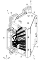
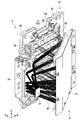
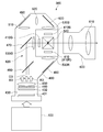
- FIG. 2 is a cross-sectional view taken along line CC of the light source device shown in FIG.
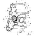
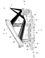
- FIG. 1 is a perspective view illustrating a basic configuration of a light source device 100 according to an embodiment of the present technology.
- FIG. 2 is a view of the light source device 100 shown in FIG. 1 with the front member 14 removed.
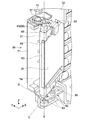
- FIG. 3 is a diagram of the light source device 100 shown in FIG. 2 with the rear member 13 and the lid member 12 removed. In FIG. 3, the heat sink 90 shown in FIGS. 1 and 2 is omitted.
- the light source device 100 is a light source for a projector of a type that emits white light by synthesizing light in a blue wavelength region from light in a blue wavelength region and a red wavelength region generated from a fluorescent material excited by the laser light. Device. This white light corresponds to the combined light in this embodiment.
- the light source device 100 includes a base portion 1 provided at the bottom and an outer frame portion 2 supported by the base portion 1.
- the base part 1 and the outer frame part 2 constitute a housing part 3 according to this embodiment.
- the housing unit 3 holds a light source unit 30 having one or more solid light sources and a phosphor unit 40 that receives the light from the light source unit 30 to generate and emit white light.
- the phosphor unit 40 is irradiated with the emitted light L from the light source unit 30 in the space 4 in the housing unit 3.
- the base portion 1 has a planar shape and an elongated shape extending in one direction.
- the long and elongated longitudinal direction of the base 1 is the left and right direction of the light source device 100, and the short direction perpendicular to the longitudinal direction is the front and rear direction. Accordingly, one of the two long portions facing each other in the short direction is the front side 5 and the other is the rear side 6.
- a portion on the front side 5 of the base portion 1 becomes the first edge portion 7, and a portion on the rear side 6 becomes the second edge portion 8. These face each other in the front-rear direction.
- the direction orthogonal to both the longitudinal direction and the short direction is the height direction of the light source device 100.
- the x-axis, y-axis, and z-axis directions are the left-right direction, the front-rear direction, and the height direction, respectively.
- the front-rear direction and the height direction correspond to the first direction and the second direction according to the present embodiment.
- the xy plane direction corresponds to the planar direction of the base portion 1.
- the outer frame portion 2 has a side wall portion 9 extending in a height direction perpendicular to the planar direction of the base portion 1 and a lid portion 10 covering the side wall portion 9.
- the two side wall members 11, the lid member 12, the rear member 13, and the front member 14 constitute the housing portion 3 including the side wall portion 9 and the lid portion 10.
- two side wall members 11 are attached to the base portion 1.
- the side wall member 11 is mounted so as to be fitted inside the wall portion 15 formed at the peripheral edge portion of the base portion 1.
- a lid member 12 is mounted on top of the two side wall members 11. As shown in FIG. 2, the lid member 12 includes a right cover part 16, a center part 17, and a left cover part 18.
- the right cover portion 16 and the left cover portion 18 are portions that respectively cover the two side wall members 11 and are symmetrical to the left and right. This shape is substantially the same as the shape of the peripheral edge portion of the base portion 1.
- the central portion 17 is a portion that connects the left and right cover portions 16 and 18.
- the central portion 17 is a concave portion and has an opening 19 on the front side thereof. The opening 19 is positioned substantially above the phosphor unit 40 held by the first edge 7 of the base portion 1.
- a bent portion 20 extending downward along the height direction is formed at the peripheral portions of the left and right cover portions 16 and 18.
- the bent portion 20 is formed over substantially the entire periphery of the left and right cover portions 16 and 18.
- the lid member 12 is mounted such that the bent portion 20 overlaps the outside of the side wall member 11. Accordingly, the two side wall members 11 and the lid member 12 are arranged such that an overlap portion 21 is formed in which two members overlap each other in two adjacent portions.
- the overlap part 21 is a part where a part of one member and a part of an adjacent member are arranged to overlap each other.
- an overlap portion 21 is formed by the upper portion of the side wall member 11 and the bent portion 20 of the lid member 12.
- the rear member 13 is mounted so as to form an overlap portion 21 and the rear side of the central portion 17 of the lid member 12.
- the rear member 13 is disposed so as to cover the space between the two light source portions 30 disposed on the second edge portion 9 of the base portion 1.
- the rear member 13 is disposed so as to overlap with a portion on the rear side of the opening 19 formed in the central portion 17 of the lid member 12.
- the front member 14 is finally attached.
- the front member 14 has a front surface portion 22 and an upper surface portion 23, and is mounted above the base portion 1 on the first edge portion 7 side.
- the front member 14 is disposed such that the front surface portion 22 sandwiches the phosphor unit 40 disposed on the first edge 7 from above.
- the upper surface portion 23 of the front member 14 is disposed so as to cover the entire central portion 17 of the lid member 12. Accordingly, the portion overlapping the central portion 17 of the rear member 13 is also covered by the upper surface portion 23 of the front member 14.
- An overlap portion 21 is formed by the two side wall portions 11 and the front surface portion 22.
- the overlap portion 21 is formed by the upper surface portion 23, the central portion 17 and the rear member 15.
- the outer frame portion 2 is configured by a plurality of frame members including the two side wall members 11, the lid member 12, the rear member 13, and the front member 14.
- the plurality of frame members are assembled so that the overwrap portion 21 is formed in an adjacent portion.
- the light blocking effect by the outer frame portion 2 can be improved.
- the outer frame portion 2 is formed integrally, for example, it is possible to prepare each frame member by processing an inexpensive sheet metal or the like, and the outer frame portion 2 can be assembled easily and inexpensively. It becomes possible.
- the shape and size of the overlap portion 21 are not limited. What is necessary is just to arrange
- the overlap portion 21 is formed in the entire adjacent portion, the light blocking effect is maintained high, but a portion that does not partially overlap may occur due to design restrictions or the like. Further, in a portion where light is likely to leak depending on the position of the light source unit 30 and the phosphor unit 40 in the housing unit 3 and the position of the optical path of the emitted light, the overlap portion 21 is enlarged to improve the light shielding property. It is possible to design such that
- the adjacent members may be arranged so as to overlap each other, and the members may not be in contact with each other, and a space may be formed therebetween. Even in this case, light leakage can be suppressed if the overlapping regions are sufficiently large. It is also possible to use the space between the members as a cooling air flow path which will be described later.
- the overlap portion 21 is also formed by the members arranged so as not to contact in this manner.
- outer frame portion 2 by configuring the outer frame portion 2 with a plurality of frame members, it becomes easy to realize a cooling structure described below.
- the plurality of frame members are mounted in order based on the base 1. And it is assembled so that it may not be disassembled in the state where lid member 12 and front member 14 which constitute lid part 10 were fixed. Accordingly, it is impossible to remove a member on the way such as the side wall member 11 in a state where the lid member 12 and the front member 14 are fixed. As a result, it is possible to realize the housing 3 that is not easily disassembled, and it is possible to realize a highly safe light source device 100 that can prevent irradiation of a human body with laser light. Further, it is possible to realize a configuration in which a fastening member such as a screw or a screw or other fixing member is used only for fixing the front member 14 and the lid member 12 and is not required for fixing other members. As a result, the number of necessary fixing members can be reduced, and the component cost can be reduced.
- a special screw is used for the solid member V1 for fixing the front member 14 and the lid member 12 shown in FIG.
- the special screw means a fixing member that can be fixed by a dedicated releasing member.
- a screw having a specially formed hole formed on the top of the screw can be used.
- the special shape include a larger number of polygonal shapes such as an octagon and a heptagon, and a star-shaped shape with a sharp point but a rounded base.
- a dedicated release member corresponding to the shape of the hole is required.
- the shape of the hole is not limited, the shape of the hole at the top of the head is not limited to a special one, and a fixing member having a special structure that is not released by a commonly used release member such as a screwdriver or a wrench is used. It only has to be done.
- the rear member 13 is fixed to the central portion 17 of the lid member 12 by a fixing member V2.
- a special screw may be used for the fixing member V2.
- a general fixing member such as a screw may be used here. That is, a special fixing member such as a special screw may be used as a fixing member that can be accessed at least directly and can be attached to a position where the casing 3 can be opened and closed. As a result, it is possible to sufficiently prevent the casing 3 from being easily disassembled.
- the light source unit 30 includes a plurality of laser light sources 31 that can emit blue laser light B1 as one or more fixed light sources (see FIG. 4).
- the plurality of laser light sources 31 has the second direction so that the blue laser light B1 is emitted toward the first edge portion 7 along the direction with the front-rear direction as the first direction as the optical axis direction. Located on the edge 8.
- a condensing optical system is disposed in front of the two light source units 30.
- the condensing optical system condenses the blue laser light B ⁇ b> 1 from the plurality of laser light sources 31 at a predetermined point of the phosphor unit 40.
- a support part 32 is illustrated in front of the light source part 30.
- the support part 32 is a member that supports the light source part 30 and the condensing optical system as one unit.
- the support part 32 constitutes a light collecting unit 33 having the light source part 30 and a light collecting optical system.
- White light is emitted along the optical axis A from the phosphor unit 40 using the blue laser light B1 collected by the light collecting unit 33 as excitation light.
- the direction of the optical axis A of white light is set to the same direction as the optical axis direction of the blue laser light B1 from the plurality of laser light sources 31. That is, the phosphor unit 40 is disposed on the first edge 7 so that white light is emitted in the same direction as the optical axis direction of the blue laser light B1.
- FIG. 4 is a plan view of the light source device 100 shown in FIG. 3 as viewed from above. In FIG. 4, illustration of the support portion 32 is omitted.
- FIG. 5 is a schematic configuration diagram for explaining light emission by the light source device 100.
- the condensing unit 33 includes a light source unit 30 including a plurality of laser light sources 31, a condensing optical system 34 that condenses the blue laser light B1 that is emitted from the plurality of laser light sources 31, and a light source. And the support part 32 which supports the part 30 and the condensing optical system 34 as one unit.
- the plurality of laser light sources 31 are, for example, blue laser light sources capable of oscillating blue laser light B1 having a peak wavelength of emission intensity within a wavelength range of 400 nm to 500 nm.
- the plurality of laser light sources 31 correspond to one or more solid light sources capable of emitting light in a predetermined wavelength region as emitted light. Other light sources such as LEDs may be used as the solid light source. Further, the light in the predetermined wavelength region is not limited to the blue laser light B1.
- the condensing optical system 34 condenses the blue laser light B1 emitted from the plurality of laser light sources 31 on the phosphor 41 from the rear side of the phosphor unit 40.
- the condensing optical system 34 of the present embodiment includes an aspheric reflecting surface 35 and a planar reflecting portion 36.
- the aspheric reflecting surface 35 reflects and collects the light emitted from the plurality of laser light sources 31.
- the plane reflecting section 36 reflects the light from the plurality of laser light sources 31 reflected by the aspheric reflecting surface 35 to the phosphor 41.
- the planar reflection unit 36 has a planar reflection surface 37 as a reflection surface that reflects light from the plurality of laser light sources 31, and reflects light to the phosphor 41 using the planar reflection surface 37.
- the blue laser beams B1 from the plurality of laser light sources 31 are condensed at a predetermined point P on the phosphor 41 included in the phosphor unit 40.
- the above-described support part 32 supports the light source part 30, the aspherical reflection surface 35, and the flat reflection part 36 as one unit.
- a phosphor wheel 42 shown in FIG. 5 is provided inside the phosphor unit 40.
- the phosphor wheel 42 includes a disk-shaped substrate 43 that transmits the blue laser light B ⁇ b> 1, and a phosphor layer 41 provided on the arrangement surface 44 of the substrate 43.
- a motor 45 for driving the phosphor wheel 42 is connected to the center of the substrate 43, and the phosphor wheel 42 has a rotation axis 46 at a normal line passing through the center of the substrate 43, and can rotate around the rotation axis 46. Is provided.
- the rotation axis 46 of the phosphor wheel 42 is provided so that the extending direction thereof is the same direction as the optical axis A passing through the approximate center of the phosphor unit 40. Further, the rotation shaft 46 is arranged at a position different from the optical axis A so that the predetermined point P of the phosphor layer 41 is located substantially at the center (on the optical axis A) of the phosphor unit 40. As shown in FIG. 4, the condensing unit 33 condenses the blue laser light B ⁇ b> 1 at a predetermined point P disposed at the approximate center of the phosphor unit 40.
- the phosphor wheel 42 is arranged so that the main surface 47 of the two main surfaces of the substrate 43 on which the phosphor layer 41 is not provided faces the light collecting unit 33 side. ing. Further, the phosphor wheel 42 is arranged so that the focal position of the blue laser light B ⁇ b> 1 condensed by the condensing unit 33 coincides with a predetermined point on the phosphor layer 41.
- the phosphor layer 41 corresponds to a light emitter that is excited by light from a plurality of laser light sources 31 and emits visible light having a wavelength longer than the wavelength of the light.
- the phosphor layer 41 includes a fluorescent material that emits fluorescence when excited by the blue laser light B1 having a center wavelength of about 445 nm.
- the phosphor layer 41 converts a part of the blue laser light B1 emitted from the plurality of laser light sources 31 into light in a wavelength region including the red wavelength region to the green wavelength region (that is, yellow light) and emits it.
- the phosphor contained in the phosphor layer 41 for example, a YAG (yttrium, aluminum, garnet) phosphor is used.
- the kind of fluorescent substance, the wavelength range of the excited light, and the wavelength range of the visible light generated by excitation are not limited.
- the phosphor layer 41 absorbs a part of the excitation light, and transmits a part of the excitation light, so that the blue laser light B1 emitted from the plurality of laser light sources 31 can also be emitted. Thereby, the light emitted from the phosphor layer 41 becomes white light due to the color mixture of the blue excitation light and the yellow fluorescence.
- the fluorescent substance layer 41 may contain the filler particle
- the laser light source 31 irradiates the phosphor layer 41 with excitation light while relatively moving the irradiation position on the phosphor layer 41.
- the phosphor unit 40 emits blue light B2 that has passed through the phosphor layer 41 and white light including green light G2 and red light R2 that are visible light from the phosphor layer 41 as combined light.
- the phosphor unit 40 corresponds to an emitting unit in the present embodiment.
- the configuration of the phosphor unit 40 is not limited.
- the phosphor wheel 42 may not be used.
- the phosphor layer 41 may be held by another holding unit, and the blue laser light from the light collecting unit 33 may be collected there. Even in this case, the phosphor layer 41 and its holding part can be sufficiently cooled by the cooling structure described later.
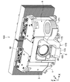
- FIG. 6 and 7 are perspective views showing a configuration example of the light collecting unit 33.
- FIG. 7 illustration of the support portion 32 is omitted.
- FIG. 8 is a plan view of the light collecting unit 33 shown in FIG. 7 as viewed from above.
- the light collecting unit 33 includes the light source unit 30, the aspherical reflection surface 35, the plane reflection unit 36, and the support unit 32 that supports these as one unit. If these can be integrally supported as one unit, the shape and size of the support portion 32 are not limited. Typically, a support portion 32 having a housing shape is used so that the blue laser light B1 does not leak to the outside. Thereby, the utilization efficiency of the blue laser beam B1 is improved.
- a laser light source array having 28 laser light sources 31 is used as the light source unit 30.
- the light source unit 30 includes a plate-like frame 49 in which an opening 48 is formed, and a mounting substrate 51 on which a plurality of laser light sources 31 are mounted is disposed on the back surface 50 (the rear side 6 surface) of the frame 49. .
- the plurality of laser light sources 31 emit blue laser light B ⁇ b> 1 along the same direction as the optical axis direction of the optical axis A toward the front side 5 through the opening 48 of the frame 49.
- Four laser light sources 31 are arranged in the left-right direction (x-axis direction) of the light source device 100 and seven in the height direction (z-axis direction).
- collimator lenses 53 are arranged on the front surface 52 (front surface 5 surface) of the frame 49 in accordance with the positions of the plurality of laser light sources 31.
- the collimator lens 53 is a rotationally symmetric aspheric lens, and makes the blue laser light B1 emitted from each laser light source 31 into a substantially parallel light beam.
- a lens unit 54 in which four collimator lenses 53 arranged in a straight line are integrally formed is used. Seven lens units 54 are arranged along the height direction. The lens unit 54 is held by a holding member 55 fixed to the frame 49.
- the collimator lens 53 may be described as the laser light source 31 in some cases.
- the configuration of the light source unit 30 is not limited, and for example, the frame 49 may not be used.
- the number and arrangement of the laser light sources 31 and the configuration of the collimator lens 53 are not limited.
- the lens unit 54 may not be used, and a collimator lens may be disposed for each laser light source 31.
- the light beams from the plurality of laser light sources 31 may be combined into a substantially parallel light beam by a single collimator lens. In the drawing, a part of the light beam of the blue laser light B1 emitted from the plurality of laser light sources 31 (collimator lenses 53) is shown.
- a reflecting member 56 having an aspheric reflecting surface 35 is disposed on the front side 5 of the plurality of laser light sources 31.
- the reflecting member 56 is disposed such that the aspheric reflecting surface 35 faces the plurality of laser light sources 31.
- the aspheric reflecting surface 35 is disposed obliquely with respect to the plane direction (xz surface direction) of the arrangement surface 52 on which the plurality of laser light sources 31 are arranged.
- the blue laser beam B1 is reflected toward the planar reflecting portion 36.
- the reflection member 56 for example, a reflection mirror is used.
- the aspherical reflecting surface 35 is typically a mirror-like concave reflecting surface, and the shape is designed so that the blue laser light B1 from the plurality of laser light sources 31 can be reflected and condensed. Further, the aspherical reflecting surface 35 may be a rotationally symmetric aspherical surface or a free-form surface having no rotationally symmetric axis. The shape of the aspherical reflecting surface 35 is determined based on the positions of the plurality of laser light sources 31, the light reflecting direction and the condensing position, the size and incident angle of the laser beam B1 incident on the aspherical reflecting surface 35, and the like. Is appropriately set.
- the material of the reflection member 56 is not limited, for example, a metal material, glass, etc. are used.
- the outer shape and size of the reflecting member 56 can be appropriately set according to the size of the irradiation region of the blue laser light B1.
- a substantially rectangular reflecting member 56 may be used, or a triangular or other polygonal reflecting member 56 may be used. Accordingly, the outer shape of the reflecting member 56 can be appropriately adjusted and reduced as compared with the case where a condensing lens is used to condense light from the plurality of laser light sources 31. As a result, the condensing optical system 34 can be made compact, and the enlargement of the light source device 100 can be suppressed.
- the reflection member 56 is supported by a support member 57.
- the support member 57 is fixed to the support portion 32 by screwing. Thereby, the reflecting member 56 is supported by the support portion 32.
- FIG. 9 is an enlarged view of the planar reflecting portion 36 supported by the support portion 32.
- the flat reflecting portion 36 includes a flat reflecting member 60 having a flat reflecting surface 37.
- the planar reflecting surface 37 reflects the blue laser light B 1 reflected by the aspheric reflecting surface 35 to a predetermined point P on the phosphor layer 41.
- the planar reflecting surface 37 is typically a mirror surface.
- a reflecting mirror is used as the planar reflecting member 60.
- the material of the planar reflecting member 60 is not limited, and for example, a metal material or glass is used.
- the planar reflecting portion 36 also has a member holding portion 61 that holds the planar reflecting member 60, a support frame 62 that supports the lower portion of the member holding portion 61 so as to be rotatable and tiltable, and a member holding on the upper side of the member holding portion 61. And a connecting portion 63 that connects the portion 61 and the support frame 62.
- the member holding portion 61 has a plate shape, and a recess 64 is formed in almost the entire area of one surface.
- a plate-like planar reflecting member 60 is fitted into the recess 64.
- the member holding portion 61 is erected along the height direction (z-axis direction).
- the normal direction of the surface on which the concave portion 64 is formed, that is, the normal direction of the planar reflecting surface 37 is a direction orthogonal to the z-axis.
- a shaft portion 65 extending in the z-axis direction is formed at the end of the member holding portion 61.
- the shaft portion 65 is formed integrally with the member holding portion 61.
- the member holding portion 61 also rotates. Accordingly, the flat reflecting member 60 held by the member holding portion 61 also moves integrally with the shaft portion 65. That is, the member holding portion 61 holds the flat reflecting surface 37 integrally with the shaft portion 65.
- the shaft portions 65 are formed so as to be linearly arranged above and below the member holding portion 61.
- An attachment portion 66 is formed above and below the member holding portion 61, and a shaft portion 65 is formed on the attachment portion 66.
- the attachment portions 66 and the shaft portions 65 formed on the upper and lower sides have the same shape.
- One of the two shaft portions 65 is inserted into a shaft support hole 67 formed in the support frame 62.
- the other shaft portion 65 is used as an operation portion 68 that is operated when adjusting the angle of the plane reflecting surface 37.
- the connecting portion 63 is attached to the attaching portion 66 on the operation portion 68 side.
- the shaft portion 65 to be inserted into the shaft support hole 67 is appropriately selected based on the arrangement position of the planar reflecting surface 37, the design of the light collecting unit 33, and the like.
- shaft portions 65 having the same shape are respectively formed on the upper and lower portions thereof. That is, the shaft portion 65 and the operation portion 68 may be formed in the same shape without distinction, and the manufacturing cost of the member holding portion 61 can be reduced. Further, since the shaft portion 65 to be inserted into the shaft support hole 67 can be selected, the degree of freedom regarding the attachment of the member holding portion 61 can be improved.
- the support frame 62 includes a lower support part 69, an upper support part 70, and a connection frame 71 that connects them.
- the lower support part 69 and the upper support part 70 are disposed so as to face each other at positions substantially equal to the lower part and the upper part of the member holding part 61 in the z-axis direction.
- the connection frame 71 extends along the z-axis direction and connects the lower support portion 69 and the upper support portion 70.
- a shaft support hole 67 that supports the shaft portion 65 of the member holding portion 61 is formed in the lower support portion 69. By inserting the shaft portion 65 into the shaft support hole 67, the member holding portion 61 is supported to be rotatable and tiltable.
- the shaft support hole 67 an oval hole having a short axis direction and a long axis direction is formed.
- a circular insertion shaft having a diameter substantially equal to the size in the short axis direction is inserted into the oval shaft support hole 67. The insertion shaft is inserted so as to be rotatable with respect to the shaft support hole 67 and tiltable in the major axis direction.
- a rotation drive system using the shaft portion 65 (axis B) as a rotation axis
- a drive mechanism is realized. This makes it possible to adjust the angle of the planar reflecting surface 37 in the rotation direction and tilt direction of the shaft portion 65.
- the configuration for supporting the shaft portion 65 so as to be rotatable and tiltable is not limited to the above-described configuration, and an arbitrary configuration may be adopted.
- the material of the support frame 62 having the lower support portion 69 and the member holding portion 61 having the shaft portion 65 is not limited, and for example, metal, plastic, or the like may be used as appropriate.
- the support frame 62 is supported by a frame support portion 74.
- the frame support portion 74 is included in the support portion 32 that supports the planar reflection portion 36 and the like as one unit.
- the support frame 62 is supported by the frame support unit 74 so as to be movable in the front-rear direction (y-axis direction) of the light source device 100.
- the member holding portion 61 and the support frame 62 move integrally. Thereby, the position of the plane reflecting surface 37 is adjusted.
- the configuration of the moving mechanism for making the support frame 62 movable is not limited.
- guide portions or the like for guiding the support frame 62 are formed above and below the frame support portion 74.
- the moving mechanism may be configured by appropriately using a spring member or the like that exhibits an elastic force in the moving direction.
- any configuration may be adopted.
- a linear drive mechanism having the axis D as the drive axis is realized by the moving mechanism.
- the adjustment of the position and angle of the flat reflecting surface 37 is performed with the screws 77 temporarily fixed.
- the angle of the plane reflecting surface 37 with the shaft 65 as the center is adjusted.
- the position of the condensing point P in the left-right direction can be adjusted.
- the tilt of the planar reflecting surface 37 can be adjusted.
- the position of the condensing point P in the height direction can be adjusted.
- the focus position of the condensing point P can be adjusted by adjusting the position of the support frame 62 in the front-rear direction.
- the two condensing units 33 are arranged at two positions that are symmetrical with respect to the axis A passing through the phosphor layer 41. With such a configuration, the number of laser light sources 31 is doubled to 56, and the brightness of white light emitted from the phosphor layer 41 can be increased.
- the blue laser light B1 from the two condensing units 33 may be condensed at one condensing point P.
- each condensing point may be set at a different position on the phosphor layer 41. Thereby, deterioration of the phosphor layer 41 can be suppressed.
- the blue laser light B1 can be easily handled. It becomes. For example, when assembling the light source device 100 or adjusting each member, it is easy to grasp the traveling direction of the blue laser light B1. Therefore, it is possible to easily implement safety measures such as preventing unexpected laser light irradiation.
- the aspherical reflecting surface 35 is used for condensing the phosphor 41.
- the light source device 100 can be made compact.
- the size of the condensing optical system 34 can be suppressed even when the number of laser light sources 31 is increased to increase the luminance.
- the aspherical reflecting surface 35 it is possible to easily realize a structure corresponding to necessary luminance and shape.
- the planar reflecting member 60 that reflects the blue laser light B1 reflected by the aspheric reflecting surface 35 toward the phosphor 41 is used.
- the degree of freedom regarding the design of the condensing optical system 34 can be increased.
- the light source device 100 can be miniaturized and a desired shape can be realized.
- the support unit 32 supports the plurality of laser light sources 31 and the condensing optical system 34 as one unit. Accordingly, it becomes easy to arrange a plurality of unitized light collecting units 33. That is, it becomes possible to deal with multi-units. Since the shape and the like of the light collecting unit 33 can be flexibly changed, the light collecting units 33 having various configurations can be appropriately combined to support various specifications.
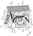
- FIG. 10 is a cross-sectional view taken along line CC of the light source device 100 shown in FIG.
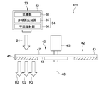
- FIG. 11 is a diagram illustrating a configuration example of a sending unit 170 for sending cooling air for cooling the phosphor unit 40 to the space part 4 in the housing part 3 of the light source device 100.
- the casing 3 has an intake port 150 for sucking cooling air and an exhaust port 151 for exhausting the cooling air W.
- the intake port 150 and the exhaust port 151 are formed so as not to face the optical path of the blue laser light B1 from the light source unit 30 to the phosphor unit 40, respectively.
- the intake port 150 and the exhaust port 151 are formed at positions where the blue laser light B1 traveling in the optical path is not visible when the space 4 of the housing unit 3 is viewed from the intake port 150 and the exhaust port 151, for example. This includes that the opening direction of the intake port 150 and the exhaust port 151 to the space 4 is not opposed to the optical axis.
- the opening direction is a direction facing the optical axis, it also includes a state in which the opening is not directly opposed to the optical axis due to the presence of another member between the optical axis.
- the phosphor unit 40 includes the phosphor wheel 42 that supports the phosphor layer 41, the motor 45 that rotates the phosphor wheel 42, and the condensing lens 79 that collects white light.
- the intake port 150 is formed at a position where the cooling air W sucked from the intake port 150 is blown to the phosphor wheel 42 and the motor 45. Thereby, the phosphor wheel 42 and the motor 45 can be effectively cooled. As a result, long-term reliability of the phosphor wheel 42 and the motor 45 can be ensured.
- the phosphor unit 40 is disposed on the first edge 7 of the base 1.
- An air inlet 150 is formed in the first edge portion 7 of the base portion 1 so as to face the phosphor unit 40.
- an opening is formed in the portion of the bottom surface 153 and the front surface 154 of the first edge 7 so as to face the phosphor wheel 42 as the air inlet 150.
- the cooling air W is sent out from the intake port 150 from the front side of the phosphor wheel 42 to the obliquely upward direction. In the vicinity of the phosphor wheel 42, an air flow is generated by the rotational centrifugal force of the wheel, so that the cooling air W is smoothly introduced.
- the exhaust port 151 is formed on the lid unit 10 side of the housing unit 3.
- the two light source units 30 are arranged on the second edge 8 of the base unit 1.
- the exhaust port 151 is formed in the vicinity of the lid 10 on the second edge 8 side.
- the exhaust port 151 is a position between the two light source units 30 and is formed at a substantially central position in the left-right direction of the lid unit 10. This position is on the optical axis A shown in FIG. 3, and is a position on the rear side of the intake port 150 (see FIG. 12).
- the cooling air is exhausted smoothly. Further, wind is sent to the heat sink 90 on the rear side of the light source unit 30 by a fan or the like. By using the flow of air from the fan, it is possible to design the cooling air more efficiently from the exhaust port.
- a space 155 is formed between the members.
- An opening portion on the most rear side of the overlap portion 21 serves as an exhaust port 151. Therefore, the cooling air W is exhausted from the exhaust port 151 through the space 155 in the overlap portion 21.
- a bent portion 160 is formed in the space 4 serving as the flow path of the cooling air W to bend the flow path of the cooling air that travels from the intake port 150 through the phosphor unit 40 to the exhaust port 151.
- the bent portion 160 is formed by appropriately arranging the bent member 161 in the course of the cooling air W, for example. By thus bending the flow path of the cooling air W from the intake port 150 to the exhaust port 151, it is possible to sufficiently suppress the blue laser light B1 from leaking from the intake port 150 or the exhaust port 151. In other words, when the intake port 150 and the exhaust port 151 are formed at a position where the blue laser beam B1 does not leak, the bent portion 160 is formed in order to efficiently blow the cooling air W traveling between them to the object to be cooled. Is valid.
- the bent portion 160 may be formed by appropriately using the members of the light collecting unit 33 and the phosphor unit 40 as the bending member 161 and appropriately designing the arrangement positions thereof.
- the flow path of the cooling air W is bent by the flat reflecting portion 36 of the light collecting unit 33. Further, the flow path of the cooling air W is bent by the rear member 13 and the front member 14 constituting the outer frame portion 2. That is, these members are used as the bending member 161. As a result, the number of parts can be reduced, and the bent portion 160 can be easily configured.
- the delivery unit 170 includes a fan 171, a fan duct 172, and a delivery duct 173.
- the fan 171 has a rotation axis set along the height direction and rotates in the horizontal direction (the xy plane direction).
- the fan 171 is disposed at a substantially central position in the height direction of the side wall portion 9.
- the fan duct 172 is connected to the fan 171 and bent downward toward the air inlet 150 formed in the base portion 1.
- the tip of the fan duct 172 is connected to the delivery duct 173.
- the delivery duct 173 is connected to the intake port 150 formed in the base portion 1, and the cooling air W is delivered from the delivery duct 173 toward the intake port 150.
- the cooling wind W is sent out by the sending unit 170, so that the phosphor wheel 42 and the motor 45 can be sufficiently cooled.
- the structure and arrangement position of the delivery unit 170 are not limited and may be designed as appropriate.
- the flow of the cooling air W from the intake port 150 to the exhaust port 151 will be described.
- the fan 171 of the delivery unit 170 is rotated, and the cooling air W is delivered to the intake port 150 via the fan duct 172 and the delivery duct 173.
- the cooling air W is sent out from the front side of the phosphor wheel 42 to the obliquely upward direction.
- the cooling air W blown to the phosphor wheel 42 and the motor 45 is bent in the path by the flat reflecting member 36 and proceeds upward.
- the cooling air W advances along the rear side of the phosphor unit 40.
- the cooling wheel 42 and the motor 45 are sufficiently cooled.
- the cooling air W travels upward from the opening 19 of the lid member 12 shown in FIG.
- the course is bent by the upper surface part 23 of the front member 14 arrange
- the cooling air advances from the intake port 150 through the phosphor unit 40 to the exhaust port 151 along the second direction orthogonal to the direction of the optical axis A.
- the cooling air W By setting the flow path of the cooling air W in the direction orthogonal to the optical axis direction, effective cooling with sufficiently suppressed leakage of the blue laser light B1 is possible.
- the cooling air W when viewed from above the light source device 100, travels in the direction opposite to the optical path of the blue laser light B1 along the direction of the optical axis A.
- Such a configuration is also advantageous in reducing light leakage.
- the present invention is not limited to the case where the flow path of the cooling air W is set so as to be orthogonal or reverse to the optical axis.
- the subsequent flow path from the opening 19 of the lid member 12 is configured as an optical attenuation path 180 having a predetermined length toward the exhaust port 151.
- the light attenuation path 180 is a part that makes it possible to sufficiently suppress the energy (intensity) of the light even if the emitted light may leak from the exhaust port 151.
- a path having a cross section substantially equal to the size of the exhaust port 151 is formed with a predetermined length toward the exhaust port 151. Even if the light travels toward the exhaust port, reflection is repeated on the inner wall of the path, and the energy of the light is reduced.
- the light attenuating portion 180 is configured by the opening 19 of the lid member 12, the upper surface portion 23 of the front member 14, and the rear member 13 located behind the opening 19.
- the outer frame portion 2 is constituted by a plurality of frame members.
- the light attenuating portion 180 can be easily formed by appropriately designing the size of the overlap portion 21 and the arrangement position of each member.
- the structure of the light attenuating unit 180 is not limited. Moreover, it is not limited to when the light attenuation part 180 is comprised by several frame members.
- the housing unit 3 that holds the light source unit 30 and the phosphor unit 40 includes the intake port 150, the exhaust port 151, and the space unit 4.
- the phosphor unit 40 having the phosphor layer 41 is cooled by the cooling air W that travels through the space portion 4 from the intake port 150 to the exhaust port 151 as a flow path.
- the intake port 150 and the exhaust port 151 are formed so as not to face the blue laser light B1 from the light source unit 30 to the fluorescent unit 40, respectively.
- effective cooling can be performed while suppressing leakage of the blue laser light B1 from the casing 3.
- the outer frame portion 2 using a plurality of frame members, the above-described cooling structure and the light attenuating portion 180 can be easily realized.
- FIG. 13 is a schematic diagram showing another configuration example in which a plurality of light collecting units are arranged.
- the four light collecting units 233 (333) may be arranged with the optical axis A symmetrical.
- each condensing unit 233 (333) adjustment is performed as appropriate so that light is condensed at a condensing point on the optical axis A.
- the number of the light collecting units to be arranged is not limited, and more light collecting units may be arranged.
- the planar shape of the arrangement surface is a planar shape viewed from the emission direction of the emitted light from the plurality of laser light sources.
- the planar shape of the plate-like frame 49 corresponds to the planar shape of the arrangement surface.
- the outer shape of the light collecting unit 233 viewed from the emission direction is also formed in a rectangular shape in accordance with the shape of the arrangement surface.
- the outer shape of the light collecting unit 333 can also be formed in a triangular shape. Since an aspheric reflecting surface is used as the condensing optical system, the number of light sources and the degree of freedom of arrangement are high. This is because the shape, size, etc. of the aspherical reflecting surface can be appropriately designed according to the light flux from the light source. As a result, a light source in which a plurality of light sources are arranged on a triangular arrangement surface as shown in FIG. 13B can be used. And the condensing unit whose external shape seen from the optical axis direction is triangular shape is realizable.
- the shape of the light collecting unit can be set freely in this way, it is easy to make the shape of the light collecting unit suitable for a multi-unit, and a plurality of light collecting units are arranged in a limited space. Is also possible. As a result, the light source device can be reduced in size.
- the planar shape of the arrangement surface is not limited to a rectangle or a triangle, but may be a polygon or a circle. What is necessary is just to set the shape of an arrangement
- positioning surface suitably according to the shape of a required condensing unit.
- FIG. 14 is a schematic diagram showing a configuration example of the projector.
- the projector 300 includes the light source device 100 according to the present technology, an illumination system 400, and a projection system 600.
- the illumination system 400 includes an image generation element 410 that generates an image based on the irradiated light, and an illumination optical system 420 that irradiates the image generation element 410 with light emitted from the light source device 100.
- the projection system 600 projects the image generated by the image generation element 410.
- the illumination system 400 functions as an image generation system in this embodiment.
- the illumination system 400 includes an integrator element 430, a polarization conversion element 440, and a condenser lens 450.
- the integrator element 430 includes a first fly-eye lens 431 having a plurality of microlenses arranged two-dimensionally, and a second having a plurality of microlenses arranged to correspond to each of the microlenses.
- the fly eye lens 432 is included.
- the parallel light incident on the integrator element 430 from the light source device 100 is divided into a plurality of light beams by the microlens of the first fly-eye lens 431 and imaged on the corresponding microlens in the second fly-eye lens 432, respectively.
- Each of the microlenses of the second fly-eye lens 432 functions as a secondary light source, and irradiates the polarization conversion element 440 with a plurality of parallel lights with uniform brightness as incident light.
- the integrator element 430 as a whole has a function of adjusting incident light irradiated from the light source device 100 to the polarization conversion element 440 into a uniform luminance distribution.
- the polarization conversion element 440 has a function of aligning the polarization state of incident light incident through the integrator element 430 and the like.
- the polarization conversion element 440 emits outgoing light including blue laser light B3, green light G3, and red light R3 through, for example, a condenser lens 450 disposed on the outgoing side of the light source device 100.
- the illumination optical system 420 includes dichroic mirrors 460 and 470, mirrors 480, 490 and 500, relay lenses 510 and 520, field lenses 530R, 530G and 530B, liquid crystal light valves 410R, 410G and 410B as image generating elements, and dichroic prism 540. Is included.
- the dichroic mirrors 460 and 470 have a property of selectively reflecting color light in a predetermined wavelength range and transmitting light in other wavelength ranges.
- a dichroic mirror 460 selectively reflects red light R3.
- the dichroic mirror 470 selectively reflects the green light G3 out of the green light G3 and the blue light B3 transmitted through the dichroic mirror 460.
- the remaining blue light B3 passes through the dichroic mirror 470. Thereby, the light emitted from the light source device 100 is separated into a plurality of color lights of different colors.
- the separated red light R3 is reflected by the mirror 480, is collimated by passing through the field lens 530R, and then enters the liquid crystal light valve 410R for modulating red light.
- the green light G3 is collimated by passing through the field lens 530G, and then enters the liquid crystal light valve 410G for green light modulation.
- the blue light B3 is reflected by the mirror 490 through the relay lens 510, and further reflected by the mirror 500 through the relay lens 520.
- the blue light B3 reflected by the mirror 500 is collimated by passing through the field lens 530B, and then enters the liquid crystal light valve 410B for modulating blue light.
- the liquid crystal light valves 410R, 410G, and 410B are electrically connected to a signal source (not shown) (such as a PC) that supplies an image signal including image information.
- the liquid crystal light valves 410R, 410G, and 410B modulate incident light for each pixel based on the supplied image signals of each color, and generate a red image, a green image, and a blue image, respectively.
- the modulated light of each color (formed image) enters the dichroic prism 540 and is synthesized.
- the dichroic prism 540 superimposes and synthesizes light of each color incident from three directions and emits the light toward the projection system 600.
- Projection system 600 includes a plurality of lenses 610 and the like, and irradiates a screen (not shown) with light synthesized by dichroic prism 540. Thereby, a full-color image is displayed.
- the projector 300 can be reduced in size by including the light source device 100 according to the present technology. In addition, by appropriately setting the shape and the like of the light source device 100, it is possible to improve the design of the outer shape of the projector 300.
- an illumination system 400 configured using a transmissive liquid crystal panel is described.
- a digital micromirror device (DMD) or the like may be used as the image generation element.
- a polarization beam splitter (PBS) instead of the dichroic prism 540, a polarization beam splitter (PBS), a color synthesis prism that synthesizes RGB video signals, a TIR (Total Internal Reflection) prism, or the like may be used.
- PBS polarization beam splitter
- TIR Total Internal Reflection
- an apparatus other than the projector may be configured as the image display apparatus according to the present technology.
- the light source device according to the present technology may be used for a device that is not an image display device.
- this technique can also take the following structures.
- a light source unit having one or more solid light sources capable of emitting light in a predetermined wavelength region as emitted light;
- a light emitting body that emits visible light in a wavelength region longer than the wavelength of the emitted light when excited by the emitted light from the light source unit, and includes the light in the predetermined wavelength range and the visible light from the light emitting body
- An emission part capable of emitting light;
- An air inlet and an exhaust port formed so as not to face the optical path of the emitted light from the light source unit to the emission unit, and the emission unit sucked from the intake port and discharged from the exhaust port, respectively.
- a light source device comprising: a space portion serving as a cooling air flow path, and a housing portion that holds the light source portion and the emission portion.
- the light source device according to (1) The light source device according to claim 1, wherein the space includes a bent portion that bends the flow path of the cooling air that travels from the intake port to the exhaust port through the emission unit.
- the emitting portion includes a wheel that supports the light emitter, a motor that rotates the wheel, and a lens that collects the combined light, The air inlet is formed at a position where the cooling air sucked from the air inlet is blown to the wheel and the motor.
- the housing part has a base part and an outer frame part supported by the base part, The emission part is held by the base part, The light source device is formed such that the air inlet is opposed to the emitting portion.
- the base portion has a planar shape, and has a first edge and a second edge facing each other in a first direction
- the outer frame portion has a side wall portion extending in a second direction perpendicular to the planar direction of the base portion, and a lid portion covering the side wall portion,
- the air inlet is formed on the base part side of the housing part
- the exhaust port is a light source device formed on the lid portion side of the housing portion.
- the light source device has the second edge portion so that the emitted light is emitted toward the first edge portion along the first direction as the optical axis direction. Placed in The emitting portion is disposed on the first edge so that the combined light is emitted in the same direction as the optical axis direction, The air inlet is formed in the first edge of the base; The exhaust port is a light source device formed in the vicinity of the lid portion on the second edge side. (7) The light source device according to any one of (1) to (6), The light source device, wherein the space portion has a light attenuation path having a predetermined length formed toward the exhaust port.
- the light source device consists of a some frame member arrange
- the light source device according to (7),
- the light attenuation path is constituted by a plurality of frame members arranged so that an overlap portion where the members overlap each other is formed in an adjacent portion as the outer frame portion.
- the light source device according to (8) or (9), The plurality of frame members are assembled so as not to be disassembled in a state where the lid portion is fixed by being mounted in order with the base portion as a reference.
Abstract
Description
前記光源部は、所定波長域の光を出射光として出射可能な1以上の固体光源を有する。
前記出射部は、前記光源部からの出射光により励起されて前記出射光の波長よりも長波長域の可視光を発する発光体を有し、前記所定波長域の光と前記発光体からの可視光とを含む合成光を出射可能である。
前記筐体部は、前記光源部から前記出射部までの前記出射光の光路と対向しないようにそれぞれ形成された吸気口及び排気口と、前記吸気口から吸入され前記排気口から排出される前記出射部を冷却するための冷却風の流路となる空間部とを有し、前記光源部と前記出射部とを保持する。
このように冷却風の流路が屈曲するように空間部が構成されることで、出射光の漏れを十分に抑えることが可能となる。
このような位置に吸気口を形成することで、ホイール及びモータを効果的に冷却することが可能となる。
この光源装置では、ベース部側に吸気口が形成され、蓋部側に排気口が形成される。従って冷却風はベース部から蓋部にかけて、第2の方向に沿うように進む。このように第2の方向に沿うように冷却風の流路が設定されてもよい。
この光源装置では、ベース部の第2の縁部に1以上の固体光源が配置され、第1の方向を光軸方向として出射光が出射される。吸気口はベース部の第1の縁部に形成され、排気口は第2の縁部側の蓋部の近傍に形成される。従って冷却風は、光軸方向と直交する第2の方向に沿うようにして、吸気口から出射部を通って排気口へ進んでいく。このように光軸方向に直交する方向に流路を設定することで、出射光の漏れを十分に抑えることが可能となる。
このように光減衰路を形成することで、排気口から出射光が漏れてしまう場合があったとしても、光減衰部によりその光のエネルギーを十分に抑えることが可能となる。
このようにオーバーラップ部が形成されるように複数の枠部材が配置されるので、出射光の漏れを十分に抑えることが可能となる。また複数の枠部材を用いることで、安価にまた簡単に筐体部を構成することが可能となる。
このように空間部が有する光減衰部が、複数の枠部材が組み立てられることで構成されてもよい。これにより光減衰部を簡単に形成することが可能となる。
これにより容易に分解することがない筐体部を実現することが可能となる。
これにより筐体部が容易に分解されることを十分に防止することが可能となる。
これにより出射部を十分に冷却することができる。
前記画像生成システムは、照射された光をもとに画像を生成する画像生成素子と、前記画像生成素子に前記光源装置からの出射光を照射する照明光学系とを有する。
前記投射システムは、前記画像生成素子により生成された画像を投射する。
図1は、本技術の一実施形態に係る光源装置100の基本的な構成を示す斜視図である。図2は、図1に示す光源装置100の前方部材14を取り外した状態の図である。図3は、図2に示す光源装置100の、後方部材13及び蓋部材12を取り外した状態の図である。図3では、図1及び図2に示すヒートシンク90の図が省略されている。
次に、上記のような構成を有する光源装置100の蛍光体ユニット40を冷却するための冷却構造について説明する。本技術に係る冷却構造により、蛍光体ホイール42及びモータ45を効果的に冷却することが可能である。
本実施形態に係る画像表示装置について説明する。ここでは、上記の実施形態で説明した光源装置を搭載可能なプロジェクタを例に挙げて説明する。図14は、そのプロジェクタの構成例を示す模式的な図である。
本技術は、以上説明した実施形態に限定されず、他の種々の実施形態を実現することができる。
(1)所定波長域の光を出射光として出射可能な1以上の固体光源を有する光源部と、
前記光源部からの出射光により励起されて前記出射光の波長よりも長波長域の可視光を発する発光体を有し、前記所定波長域の光と前記発光体からの可視光とを含む合成光を出射可能な出射部と、
前記光源部から前記出射部までの前記出射光の光路と対向しないようにそれぞれ形成された吸気口及び排気口と、前記吸気口から吸入され前記排気口から排出される前記出射部を冷却するための冷却風の流路となる空間部とを有し、前記光源部と前記出射部とを保持する筐体部と
を具備する光源装置。
(2)(1)に記載の光源装置であって、
前記空間部は、前記吸気口から前記出射部を通って前記排気口へと進む前記冷却風の流路を屈曲させる屈曲部を有する
光源装置。
(3)(1)又は(2)に記載の光源装置であって、
前記出射部は、前記発光体を支持するホイールと、前記ホイールを回転させるモータと、前記合成光を集光するレンズとを有し、
前記吸気口は、前記吸気口から吸入された前記冷却風が前記ホイール及び前記モータに送風される位置に形成される
光源装置。
(4)(1)から(3)のうちいずれか1つに記載の光源装置であって、
前記筐体部は、ベース部と、前記ベース部に支持される外枠部とを有し、
前記出射部は、前記ベース部に保持され、
前記吸気口は、前記出射部に対向するように形成される
光源装置。
(5)(4)に記載の光源装置であって、
前記ベース部は、平面形状でなり、第1の方向で互いに対向する第1の縁部及び第2の縁部を有し、
前記外枠部は、前記ベース部の平面方向に垂直な第2の方向に延在する側壁部と、前記側壁部を覆う蓋部とを有し、
前記吸気口は、前記筐体部の前記ベース部側に形成され、
前記排気口は、前記筐体部の前記蓋部側に形成される
光源装置。
(6)(5)に記載の光源装置であって、
前記1以上の固体光源は、前記第1の方向を光軸方向として、その方向に沿って前記第1の縁部側に向けて前記出射光が出射されるように、前記第2の縁部に配置され、
前記出射部は、前記光軸方向と同じ方向で前記合成光が出射されるように、前記第1の縁部に配置され、
前記吸気口は、前記ベース部の前記第1の縁部に形成され、
前記排気口は、前記第2の縁部側の前記蓋部の近傍に形成される
光源装置。
(7)(1)から(6)のうちいずれか1つに記載の光源装置であって、
前記空間部は、前記排気口に向けて形成された所定の長さを有する光減衰路を有する
光源装置。
(8)(4)から(7)のうちいずれか1つに記載の光源装置であって、
前記外枠部は、隣接する部分に互いの部材が重なるオーバーラップ部が形成されるように配置された複数の枠部材からなる
光源装置。
(9)(7)に記載の光源装置であって、
前記光減衰路は、前記外枠部として隣接する部分に互いの部材が重なるオーバーラップ部が形成されるように配置される複数の枠部材により構成される
光源装置。
(10)(8)又は(9)に記載の光源装置であって、
前記複数の枠部材は、前記ベース部を基準として順番に装着されることで、前記蓋部が固定された状態では解体されないように組み立てられている
光源装置。
(11)(10)に記載の光源装置であって、
前記蓋部は、専用の解除部材により固定が解除可能な固定部材により固定される
光源装置。
(12)(1)から(11)のうちいずれか1つに記載の光源装置であって、
前記吸気口に前記冷却風を送る送出部をさらに具備する
光源装置。
B1…青色レーザ光
G2…緑色光
R2…赤色光
W…白色光
1…ベース部
2…外枠部
3…筐体部
4…空間部
7…第1の縁部
8…第2の縁部
9…側壁部
10…蓋部
11…側壁部材
12…蓋部材
13…後方部材
14…前方部材
21…オーバーラップ部
30…光源部
31…レーザ光源
40…蛍光体ユニット
41…蛍光体層
42…蛍光体ホイール
45…モータ
150…吸気口
151…排気口
160…屈曲部
170…送出ユニット
180…光減衰部
300…プロジェクタ
400…照明システム
410…画像生成素子
420…照明光学系
600…投射システム
Claims (13)
- 所定波長域の光を出射光として出射可能な1以上の固体光源を有する光源部と、
前記光源部からの出射光により励起されて前記出射光の波長よりも長波長域の可視光を発する発光体を有し、前記所定波長域の光と前記発光体からの可視光とを含む合成光を出射可能な出射部と、
前記光源部から前記出射部までの前記出射光の光路と対向しないようにそれぞれ形成された吸気口及び排気口と、前記吸気口から吸入され前記排気口から排出される前記出射部を冷却するための冷却風の流路となる空間部とを有し、前記光源部と前記出射部とを保持する筐体部と
を具備する光源装置。 - 請求項1に記載の光源装置であって、
前記空間部は、前記吸気口から前記出射部を通って前記排気口へと進む前記冷却風の流路を屈曲させる屈曲部を有する
光源装置。 - 請求項1に記載の光源装置であって、
前記出射部は、前記発光体を支持するホイールと、前記ホイールを回転させるモータと、前記合成光を集光するレンズとを有し、
前記吸気口は、前記吸気口から吸入された前記冷却風が前記ホイール及び前記モータに送風される位置に形成される
光源装置。 - 請求項1に記載の光源装置であって、
前記筐体部は、ベース部と、前記ベース部に支持される外枠部とを有し、
前記出射部は、前記ベース部に保持され、
前記吸気口は、前記出射部に対向するように形成される
光源装置。 - 請求項4に記載の光源装置であって、
前記ベース部は、平面形状でなり、第1の方向で互いに対向する第1の縁部及び第2の縁部を有し、
前記外枠部は、前記ベース部の平面方向に垂直な第2の方向に延在する側壁部と、前記側壁部を覆う蓋部とを有し、
前記吸気口は、前記筐体部の前記ベース部側に形成され、
前記排気口は、前記筐体部の前記蓋部側に形成される
光源装置。 - 請求項5に記載の光源装置であって、
前記1以上の固体光源は、前記第1の方向を光軸方向として、その方向に沿って前記第1の縁部側に向けて前記出射光が出射されるように、前記第2の縁部に配置され、
前記出射部は、前記光軸方向と同じ方向で前記合成光が出射されるように、前記第1の縁部に配置され、
前記吸気口は、前記ベース部の前記第1の縁部に形成され、
前記排気口は、前記第2の縁部側の前記蓋部の近傍に形成される
光源装置。 - 請求項1に記載の光源装置であって、
前記空間部は、前記排気口に向けて形成された所定の長さを有する光減衰路を有する
光源装置。 - 請求項4に記載の光源装置であって、
前記外枠部は、隣接する部分に互いの部材が重なるオーバーラップ部が形成されるように配置された複数の枠部材からなる
光源装置。 - 請求項7に記載の光源装置であって、
前記光減衰路は、前記外枠部として隣接する部分に互いの部材が重なるオーバーラップ部が形成されるように配置される複数の枠部材により構成される
光源装置。 - 請求項8に記載の光源装置であって、
前記複数の枠部材は、前記ベース部を基準として順番に装着されることで、前記蓋部が固定された状態では解体されないように組み立てられている
光源装置。 - 請求項10に記載の光源装置であって、
前記蓋部は、専用の解除部材により固定が解除可能な固定部材により固定される
光源装置。 - 請求項1に記載の光源装置であって、
前記吸気口に前記冷却風を送る送出部をさらに具備する
光源装置。 - (a)所定波長域の光を出射光として出射可能な1以上の固体光源を有する光源部と、
前記光源部からの出射光により励起されて前記出射光の波長よりも長波長域の可視光を発する発光体を有し、前記所定波長域の光と前記発光体からの可視光とを含む合成光を出射可能な出射部と、
前記光源部から前記出射部までの前記出射光の光路と対向しないようにそれぞれ形成された吸気口及び排気口と、前記吸気口から吸入され前記排気口から排出される前記出射部を冷却するための冷却風の流路となる空間部とを有し、前記光源部と前記出射部とを保持する筐体部と
を有する光源装置と、
(b)照射された光をもとに画像を生成する画像生成素子と、前記画像生成素子に前記光源装置からの出射光を照射する照明光学系とを有する画像生成システムと、
(c)前記画像生成素子により生成された画像を投射する投射システムと
を具備する画像表示装置。
Priority Applications (6)
| Application Number | Priority Date | Filing Date | Title |
|---|---|---|---|
| US14/784,081 US9702538B2 (en) | 2013-06-06 | 2014-05-02 | Light source apparatus and image display apparatus |
| CN201480030503.1A CN105308502B (zh) | 2013-06-06 | 2014-05-02 | 光源设备和图像显示设备 |
| EP14808163.1A EP3007000A4 (en) | 2013-06-06 | 2014-05-02 | LIGHT SOURCE DEVICE, AND IMAGE DISPLAY DEVICE |
| JP2015521271A JP6402712B2 (ja) | 2013-06-06 | 2014-05-02 | 光源装置、及び画像表示装置 |
| US15/613,917 US10113736B2 (en) | 2013-06-06 | 2017-06-05 | Light source apparatus and image display apparatus |
| US16/141,178 US10731841B2 (en) | 2013-06-06 | 2018-09-25 | Light source apparatus and image display apparatus |
Applications Claiming Priority (2)
| Application Number | Priority Date | Filing Date | Title |
|---|---|---|---|
| JP2013119834 | 2013-06-06 | ||
| JP2013-119834 | 2013-06-06 |
Related Child Applications (2)
| Application Number | Title | Priority Date | Filing Date |
|---|---|---|---|
| US14/784,081 A-371-Of-International US9702538B2 (en) | 2013-06-06 | 2014-05-02 | Light source apparatus and image display apparatus |
| US15/613,917 Continuation US10113736B2 (en) | 2013-06-06 | 2017-06-05 | Light source apparatus and image display apparatus |
Publications (1)
| Publication Number | Publication Date |
|---|---|
| WO2014196126A1 true WO2014196126A1 (ja) | 2014-12-11 |
Family
ID=52007787
Family Applications (1)
| Application Number | Title | Priority Date | Filing Date |
|---|---|---|---|
| PCT/JP2014/002408 WO2014196126A1 (ja) | 2013-06-06 | 2014-05-02 | 光源装置、及び画像表示装置 |
Country Status (5)
| Country | Link |
|---|---|
| US (3) | US9702538B2 (ja) |
| EP (1) | EP3007000A4 (ja) |
| JP (2) | JP6402712B2 (ja) |
| CN (1) | CN105308502B (ja) |
| WO (1) | WO2014196126A1 (ja) |
Cited By (3)
| Publication number | Priority date | Publication date | Assignee | Title |
|---|---|---|---|---|
| WO2016116979A1 (ja) * | 2015-01-20 | 2016-07-28 | ソニー株式会社 | 光源装置およびプロジェクタ |
| CN108604050A (zh) * | 2016-01-20 | 2018-09-28 | 精工爱普生株式会社 | 光源装置和投影仪 |
| WO2019098125A1 (ja) * | 2017-11-20 | 2019-05-23 | シャープ株式会社 | 光源装置、および投影装置 |
Families Citing this family (1)
| Publication number | Priority date | Publication date | Assignee | Title |
|---|---|---|---|---|
| JP6807036B2 (ja) * | 2018-03-26 | 2021-01-06 | カシオ計算機株式会社 | 光源装置及び投影装置 |
Citations (5)
| Publication number | Priority date | Publication date | Assignee | Title |
|---|---|---|---|---|
| JP2007193990A (ja) * | 2006-01-17 | 2007-08-02 | Mitsubishi Heavy Ind Ltd | 光源用ランプおよびプロジェクター |
| JP2011075898A (ja) * | 2009-09-30 | 2011-04-14 | Casio Computer Co Ltd | プロジェクタ |
| JP2012013897A (ja) * | 2010-06-30 | 2012-01-19 | Jvc Kenwood Corp | 光源装置および投射型表示装置 |
| JP2012018762A (ja) * | 2010-07-06 | 2012-01-26 | Seiko Epson Corp | 光源装置およびプロジェクター |
| JP2012173593A (ja) | 2011-02-23 | 2012-09-10 | Seiko Epson Corp | 光源装置、およびプロジェクター |
Family Cites Families (18)
| Publication number | Priority date | Publication date | Assignee | Title |
|---|---|---|---|---|
| JP2004053692A (ja) * | 2002-07-16 | 2004-02-19 | Canon Inc | 投射型表示装置 |
| JP4124201B2 (ja) * | 2005-02-02 | 2008-07-23 | 船井電機株式会社 | プロジェクタ |
| CA2636786C (en) | 2006-01-17 | 2010-12-21 | Mitsubishi Heavy Industries, Ltd. | Light-source lamp and projector |
| JP5163927B2 (ja) * | 2006-08-28 | 2013-03-13 | カシオ計算機株式会社 | プロジェクタ |
| JP4662185B2 (ja) * | 2008-05-15 | 2011-03-30 | カシオ計算機株式会社 | 光源装置及びプロジェクタ |
| US8664858B2 (en) * | 2008-09-05 | 2014-03-04 | Martin Professional A/S | Light fixture with an electrodeless plasma source |
| TWI405027B (zh) * | 2009-08-06 | 2013-08-11 | Qisda Corp | 投影機 |
| US20110188008A1 (en) * | 2010-01-29 | 2011-08-04 | Sanyo Electric Co., Ltd. | Projection display apparatus |
| JP5671666B2 (ja) * | 2010-02-12 | 2015-02-18 | 日立マクセル株式会社 | 固体光源装置及び投射型表示装置 |
| JP5556256B2 (ja) * | 2010-03-11 | 2014-07-23 | パナソニック株式会社 | 照明装置および投写型画像表示装置 |
| JP4831587B1 (ja) * | 2010-08-23 | 2011-12-07 | パナソニック株式会社 | レーザ光源装置 |
| JP5534334B2 (ja) * | 2010-09-24 | 2014-06-25 | カシオ計算機株式会社 | 蛍光発光装置及びプロジェクタ |
| CN102455580A (zh) * | 2010-10-21 | 2012-05-16 | 中强光电股份有限公司 | 用于投影光学系统的散热模组 |
| US20120182527A1 (en) * | 2011-01-18 | 2012-07-19 | Panasonic Corporation | Image display apparatus |
| JP5551639B2 (ja) * | 2011-03-11 | 2014-07-16 | パナソニック株式会社 | 画像表示装置 |
| JP5331156B2 (ja) * | 2011-04-28 | 2013-10-30 | シャープ株式会社 | 投光ユニットおよび投光装置 |
| US9329465B2 (en) * | 2011-09-20 | 2016-05-03 | Nec Display Solutions, Ltd. | Light source device and projection-type display device including first and second light emitting elements and air flow device |
| US8967811B2 (en) * | 2012-01-20 | 2015-03-03 | Lumencor, Inc. | Solid state continuous white light source |
-
2014
- 2014-05-02 WO PCT/JP2014/002408 patent/WO2014196126A1/ja active Application Filing
- 2014-05-02 JP JP2015521271A patent/JP6402712B2/ja active Active
- 2014-05-02 US US14/784,081 patent/US9702538B2/en active Active
- 2014-05-02 EP EP14808163.1A patent/EP3007000A4/en not_active Withdrawn
- 2014-05-02 CN CN201480030503.1A patent/CN105308502B/zh not_active Expired - Fee Related
-
2017
- 2017-06-05 US US15/613,917 patent/US10113736B2/en active Active
-
2018
- 2018-09-13 JP JP2018171137A patent/JP6669222B2/ja active Active
- 2018-09-25 US US16/141,178 patent/US10731841B2/en active Active
Patent Citations (5)
| Publication number | Priority date | Publication date | Assignee | Title |
|---|---|---|---|---|
| JP2007193990A (ja) * | 2006-01-17 | 2007-08-02 | Mitsubishi Heavy Ind Ltd | 光源用ランプおよびプロジェクター |
| JP2011075898A (ja) * | 2009-09-30 | 2011-04-14 | Casio Computer Co Ltd | プロジェクタ |
| JP2012013897A (ja) * | 2010-06-30 | 2012-01-19 | Jvc Kenwood Corp | 光源装置および投射型表示装置 |
| JP2012018762A (ja) * | 2010-07-06 | 2012-01-26 | Seiko Epson Corp | 光源装置およびプロジェクター |
| JP2012173593A (ja) | 2011-02-23 | 2012-09-10 | Seiko Epson Corp | 光源装置、およびプロジェクター |
Non-Patent Citations (1)
| Title |
|---|
| See also references of EP3007000A4 |
Cited By (7)
| Publication number | Priority date | Publication date | Assignee | Title |
|---|---|---|---|---|
| WO2016116979A1 (ja) * | 2015-01-20 | 2016-07-28 | ソニー株式会社 | 光源装置およびプロジェクタ |
| US10520799B2 (en) | 2015-01-20 | 2019-12-31 | Sony Corporation | Light source apparatus and projector with rotor cooling mechanism |
| CN108604050A (zh) * | 2016-01-20 | 2018-09-28 | 精工爱普生株式会社 | 光源装置和投影仪 |
| EP3407132A4 (en) * | 2016-01-20 | 2019-09-04 | Seiko Epson Corporation | LIGHT SOURCE DEVICE AND PROJECTOR |
| WO2019098125A1 (ja) * | 2017-11-20 | 2019-05-23 | シャープ株式会社 | 光源装置、および投影装置 |
| JPWO2019098125A1 (ja) * | 2017-11-20 | 2020-12-24 | シャープ株式会社 | 光源装置、および投影装置 |
| US10989996B2 (en) | 2017-11-20 | 2021-04-27 | Sharp Kabushiki Kaisha | Light source device and projector |
Also Published As
| Publication number | Publication date |
|---|---|
| US10113736B2 (en) | 2018-10-30 |
| US20190024880A1 (en) | 2019-01-24 |
| JP2018200490A (ja) | 2018-12-20 |
| US10731841B2 (en) | 2020-08-04 |
| CN105308502B (zh) | 2017-12-19 |
| US20170268764A1 (en) | 2017-09-21 |
| US9702538B2 (en) | 2017-07-11 |
| JP6402712B2 (ja) | 2018-10-10 |
| EP3007000A1 (en) | 2016-04-13 |
| EP3007000A4 (en) | 2016-11-09 |
| JPWO2014196126A1 (ja) | 2017-02-23 |
| US20160053981A1 (en) | 2016-02-25 |
| CN105308502A (zh) | 2016-02-03 |
| JP6669222B2 (ja) | 2020-03-18 |
Similar Documents
| Publication | Publication Date | Title |
|---|---|---|
| JP6236891B2 (ja) | 光源装置、及び画像表示装置 | |
| JP6477465B2 (ja) | 画像表示装置、及び光源装置 | |
| US9249949B2 (en) | Lighting device and projection-type display device using the same including a color-combining prism | |
| JP6295960B2 (ja) | 光源ユニット、光源装置、及び画像表示装置 | |
| JP6669222B2 (ja) | 光源装置、及び画像表示装置 | |
| JP5928300B2 (ja) | 光源ユニット、光源装置、及び画像表示装置 | |
| WO2016167110A1 (ja) | 照明装置および投影型表示装置 | |
| WO2015155917A1 (ja) | 光源装置、及び画像表示装置 | |
| JPWO2015155917A6 (ja) | 光源装置、及び画像表示装置 | |
| JP4211791B2 (ja) | 光源装置、およびプロジェクタ | |
| JP6881460B2 (ja) | 投射型表示装置 | |
| JP6233442B2 (ja) | 光源ユニット、光源装置、及び画像表示装置 | |
| JP6206532B2 (ja) | 光源装置、及び画像表示装置 | |
| JP4211790B2 (ja) | 光源装置、およびプロジェクタ | |
| JP2012074242A (ja) | 発光装置およびプロジェクタ |
Legal Events
| Date | Code | Title | Description |
|---|---|---|---|
| WWE | Wipo information: entry into national phase |
Ref document number: 201480030503.1 Country of ref document: CN |
|
| 121 | Ep: the epo has been informed by wipo that ep was designated in this application |
Ref document number: 14808163 Country of ref document: EP Kind code of ref document: A1 |
|
| WWE | Wipo information: entry into national phase |
Ref document number: 2014808163 Country of ref document: EP |
|
| WWE | Wipo information: entry into national phase |
Ref document number: 14784081 Country of ref document: US |
|
| ENP | Entry into the national phase |
Ref document number: 2015521271 Country of ref document: JP Kind code of ref document: A |
|
| NENP | Non-entry into the national phase |
Ref country code: DE |