WO2020039619A1 - リレー - Google Patents
リレー Download PDFInfo
- Publication number
- WO2020039619A1 WO2020039619A1 PCT/JP2019/006169 JP2019006169W WO2020039619A1 WO 2020039619 A1 WO2020039619 A1 WO 2020039619A1 JP 2019006169 W JP2019006169 W JP 2019006169W WO 2020039619 A1 WO2020039619 A1 WO 2020039619A1
- Authority
- WO
- WIPO (PCT)
- Prior art keywords
- contact
- movable contact
- wall
- fixed
- movable
- Prior art date
- Legal status (The legal status is an assumption and is not a legal conclusion. Google has not performed a legal analysis and makes no representation as to the accuracy of the status listed.)
- Ceased
Links
Images



Classifications
-
- H—ELECTRICITY
- H01—ELECTRIC ELEMENTS
- H01H—ELECTRIC SWITCHES; RELAYS; SELECTORS; EMERGENCY PROTECTIVE DEVICES
- H01H50/00—Details of electromagnetic relays
- H01H50/54—Contact arrangements
- H01H50/546—Contact arrangements for contactors having bridging contacts
-
- H—ELECTRICITY
- H01—ELECTRIC ELEMENTS
- H01H—ELECTRIC SWITCHES; RELAYS; SELECTORS; EMERGENCY PROTECTIVE DEVICES
- H01H50/00—Details of electromagnetic relays
- H01H50/02—Bases; Casings; Covers
-
- H—ELECTRICITY
- H01—ELECTRIC ELEMENTS
- H01H—ELECTRIC SWITCHES; RELAYS; SELECTORS; EMERGENCY PROTECTIVE DEVICES
- H01H50/00—Details of electromagnetic relays
- H01H50/14—Terminal arrangements
-
- H—ELECTRICITY
- H01—ELECTRIC ELEMENTS
- H01H—ELECTRIC SWITCHES; RELAYS; SELECTORS; EMERGENCY PROTECTIVE DEVICES
- H01H50/00—Details of electromagnetic relays
- H01H50/16—Magnetic circuit arrangements
- H01H50/18—Movable parts of magnetic circuits, e.g. armature
-
- H—ELECTRICITY
- H01—ELECTRIC ELEMENTS
- H01H—ELECTRIC SWITCHES; RELAYS; SELECTORS; EMERGENCY PROTECTIVE DEVICES
- H01H9/00—Details of switching devices, not covered by groups H01H1/00 - H01H7/00
- H01H9/30—Means for extinguishing or preventing arc between current-carrying parts
-
- H—ELECTRICITY
- H01—ELECTRIC ELEMENTS
- H01H—ELECTRIC SWITCHES; RELAYS; SELECTORS; EMERGENCY PROTECTIVE DEVICES
- H01H9/00—Details of switching devices, not covered by groups H01H1/00 - H01H7/00
- H01H9/30—Means for extinguishing or preventing arc between current-carrying parts
- H01H9/302—Means for extinguishing or preventing arc between current-carrying parts wherein arc-extinguishing gas is evolved from stationary parts
-
- H—ELECTRICITY
- H01—ELECTRIC ELEMENTS
- H01H—ELECTRIC SWITCHES; RELAYS; SELECTORS; EMERGENCY PROTECTIVE DEVICES
- H01H9/00—Details of switching devices, not covered by groups H01H1/00 - H01H7/00
- H01H9/30—Means for extinguishing or preventing arc between current-carrying parts
- H01H9/44—Means for extinguishing or preventing arc between current-carrying parts using blow-out magnet
- H01H9/443—Means for extinguishing or preventing arc between current-carrying parts using blow-out magnet using permanent magnets
-
- H—ELECTRICITY
- H01—ELECTRIC ELEMENTS
- H01H—ELECTRIC SWITCHES; RELAYS; SELECTORS; EMERGENCY PROTECTIVE DEVICES
- H01H50/00—Details of electromagnetic relays
- H01H50/02—Bases; Casings; Covers
- H01H2050/028—Means to improve the overall withstanding voltage, e.g. creepage distances
Definitions
- the present invention relates to a relay.
- Some relays have a structure for extinguishing an arc generated at a contact.
- a wall portion is disposed inside a fixed contact portion.
- the fixed contact portion includes a fixed contact contact portion and a fixed contact pedestal portion to which the fixed contact contact portion is fixed.
- the height of the wall portion is higher than the fixed contact pedestal portion and lower than the height of the fixed contact contact portion.
- Patent Literature 1 the creepage distance of the arc current increases due to the above-described wall. This makes it difficult for the arc current to be short-circuited. In addition, the height of the wall portion as described above prevents the operation of the movable contact portion from being hindered.
- Patent Literature 1 the wall cannot be raised to avoid interference with the movable contact. Therefore, it is difficult to improve the arc breaking performance of the wall.
- An object of the present invention is to improve arc breaking performance of a relay while avoiding hindering the operation of a movable contact piece.
- the relay includes a movable contact piece, a first fixed terminal, a second fixed terminal, a driving device, and a wall.
- the movable contact piece includes a first movable contact and a second movable contact arranged apart from each other in the longitudinal direction of the movable contact piece.
- the first fixed terminal includes a first fixed contact arranged to face the first movable contact.
- the second fixed terminal includes a second fixed contact arranged to face the second movable contact.
- the drive device moves the movable contact piece in a direction in which the first movable contact and the second movable contact contact the first fixed contact and the second fixed contact and in a direction in which the first movable contact and the second movable contact are separated from each other.
- the wall is disposed inside the first fixed contact and the second fixed contact in the longitudinal direction. At least a portion of the wall is disposed at a position beyond the first fixed contact and the second fixed contact to the movable contact piece side in the moving direction of the movable contact piece.
- the movable contact piece has a shape avoiding the wall when the first movable contact and the second movable contact are in contact with the first fixed contact and the second fixed contact.
- the wall portion is disposed at a position beyond the first fixed contact and the second fixed contact toward the movable contact piece in the moving direction of the movable contact piece. Therefore, when the arc is extended toward the inside of the first fixed contact and the second fixed contact, the arc easily hits the wall. Thereby, the arc can be extinguished quickly.
- the movable contact piece has a shape avoiding the wall when the first movable contact and the second movable contact are in contact with the first fixed contact and the second fixed contact. Therefore, even if the wall is arranged as described above, interference between the movable contact piece and the wall can be avoided.
- the wall may be formed of an arc-extinguishing material that generates an arc-extinguishing gas by the heat of the arc. In this case, the arc can be extinguished more quickly by generating the arc extinguishing gas from the wall.
- the movable contact piece may have a concave shape in a direction away from the wall. In this case, interference with the wall can be avoided by the concave shape of the movable contact piece.
- the movable contact piece may include a bent portion curved in a direction away from the wall. In this case, interference with the wall can be avoided by the shape of the bent portion of the movable contact piece. Further, the starting point of the arc can be limited to the bent portion.
- the bent portion may be arranged to face the wall. In this case, the arc extended from the bent portion easily hits the wall. Thereby, the arc can be extinguished more quickly.
- the movable contact piece may include a hole arranged to face the wall.
- the wall is arranged in the hole in a state where the first movable contact and the second movable contact are in contact with the first fixed contact and the second fixed contact, thereby avoiding interference with the wall. be able to.
- the movable contact piece may include a concave portion arranged to face the wall.
- the wall is disposed in the recess, thereby avoiding interference with the wall. be able to.
- the movable contact piece may include a first contact support and a second contact support.
- the first contact support may support the first movable contact.
- the second contact support may support the second movable contact.
- the inner end of the first contact support and the inner end of the second contact support may be arranged apart from each other.
- the wall may be disposed to face a space between the inner end of the first contact support and the inner end of the second contact support. In this case, in a state where the first movable contact and the second movable contact are in contact with the first fixed contact and the second fixed contact, the wall is formed between the inner end of the first contact support and the second contact support.
- the wall is formed of the first movable contact and the first fixed contact. May overlap. In this case, the arc easily hits the wall. Thereby, the arc can be extinguished more quickly.
- the first fixed terminal may include a contact support portion and an intermediate portion.
- the contact support may support the first fixed contact and extend outward from the first fixed contact in the longitudinal direction.
- the intermediate portion may extend from the contact support portion in a direction parallel to the moving direction of the movable contact piece.
- FIG. 6 is a sectional view taken along line VI-VI in FIG. 5. It is a top view showing composition in a contact case of a relay concerning a 2nd embodiment. It is a top view showing composition in a contact case of a relay concerning a 3rd embodiment.
- FIG. 1 is a side sectional view showing a relay 1a according to the first embodiment.
- the relay 1a includes a case 2, a contact device 3, and a driving device 4.
- the directions of up, down, left, and right mean the directions of up, down, left, and right in FIG.
- the front-back direction means a direction perpendicular to the paper surface of FIG.
- the definition of these directions does not limit the arrangement direction of the relay 1a.
- the case 2 houses the contact device 3 and the driving device 4.
- the case 2 is formed of an insulating resin.
- the case 2 includes a case main body 2a and a lid 2b.
- the contact device 3 and the driving device 4 are arranged in the case main body 2a.
- the lid 2b is separate from the case body 2a.
- the lid 2b is attached to the case body 2a.
- the case main body 2 a includes a contact case 18 and an outer case 19.
- the contact case 18 partitions the inside of the case 2 into a first storage section S1 and a second storage section S2.
- the contact device 3 is arranged in the first storage section S1.
- the driving device 4 is disposed in the second storage section S2.
- the outer case 19 houses the contact case 18 therein.
- the contact device 3 includes a first fixed terminal 5, a second fixed terminal 6, a movable contact piece 7, and a contact piece holding section 8.
- the first fixed terminal 5, the second fixed terminal 6, and the movable contact piece 7 are formed of a conductive material such as copper.
- the first fixed terminal 5 includes a first fixed contact 11.
- the second fixed terminal 6 includes a second fixed contact 12.
- the first fixed contact 11 and the second fixed contact 12 are arranged apart from each other in the left-right direction.
- the movable contact piece 7 extends in the left-right direction.
- the longitudinal direction of the movable contact piece 7 coincides with the left-right direction.
- the movable contact piece 7 includes a first movable contact 13 and a second movable contact 14.
- the first movable contact 13 and the second movable contact 14 are arranged apart from each other in the left-right direction.
- the first movable contact 13 is arranged to face the first fixed contact 11.
- the second movable contact 14 is arranged to face the second fixed contact 12.
- the movable contact piece 7 includes a first end 7a and a second end 7b.
- the first end 7a is one end of the movable contact piece 7 in the left-right direction.
- the second end 7b is the other end of the movable contact piece 7 in the left-right direction.
- the first end 7 a is the left end of the movable contact piece 7.
- the second end 7 b is the right end of the movable contact piece 7.
- the first movable contact 13 is disposed between the center of the movable contact piece 7 in the left-right direction and the first end 7a.
- the second movable contact 14 is disposed between the center of the movable contact piece 7 in the left-right direction and the second end 7b.
- the movable contact piece 7 is arranged so as to be movable in the vertical direction. Specifically, the movable contact piece 7 is arranged so as to be movable in the contact direction Z1 and the separation direction Z2.
- the contact direction Z1 is a direction in which the first movable contact 13 and the second movable contact 14 contact the first fixed contact 11 and the second fixed contact 12 (downward in FIG. 1).
- the separation direction Z2 is a direction in which the first movable contact 13 and the second movable contact 14 are separated from the first fixed contact 11 and the second fixed contact 12 (upward in FIG. 1).
- the contact piece holding section 8 holds the movable contact piece 7.
- the contact piece holding section 8 holds the movable contact piece 7 at the center of the movable contact piece 7 in the left-right direction. Therefore, the contact piece holding section 8 holds the movable contact piece 7 at a position between the first movable contact 13 and the second movable contact 14 in the left-right direction.
- the contact piece holding section 8 includes a drive shaft 15, a holder 16, and a contact spring 17.
- the drive shaft 15 extends in the up-down direction.
- the drive shaft 15 connects the movable contact piece 7 and the drive device 4.
- the drive shaft 15 is arranged movably in the contact direction Z1 and the separation direction Z2.
- the holder 16 is connected to the movable contact piece 7 and holds the movable contact piece 7.
- the contact spring 17 is arranged between the drive shaft 15 and the holder 16.
- the drive shaft 15 is connected to a holder 16 via a contact spring 17.
- the first fixed terminal 5 includes a first contact support part 21, a first intermediate part 22, and a first external connection part 24.
- the first contact support 21 supports the first fixed contact 11 in the case 2.
- the first contact support 21 extends outward from the first fixed contact 11 in the left-right direction.
- the outer side in the left-right direction means a direction away from the center axis of the drive shaft 15 in the left-right direction.
- the inner side in the left-right direction means a direction approaching the center axis of the drive shaft 15 in the left-right direction.
- the first intermediate portion 22 is located between the first contact support portion 21 and the first external connection portion 24.
- the first intermediate portion 22 extends from the first contact support portion in a direction parallel to the moving direction of the movable contact piece 7, that is, in a vertical direction. More specifically, the first intermediate portion 22 extends upward from the first contact support portion 21.
- the first external connection part 24 extends leftward from the first intermediate part 22. The first external connection portion 24 protrudes outside the case 2.
- the first fixed terminal 5 has a shape that is bent between the first contact support 21 and the first intermediate part 22 and between the first intermediate part 22 and the first external connection part 24.
- the first contact support portion 21, the first intermediate portion 22, and the first external connection portion 24 may be integrally formed.
- the first contact support portion 21, the first intermediate portion 22, and the first external connection portion 24 may be separate from each other, and may be connected to each other by fixing means such as welding.
- the second fixed terminal 6 includes a second contact support part 31, a second intermediate part 32, and a second external connection part.
- the second contact support portion 31 supports the second fixed contact 12 in the case 2.
- the second fixed terminal 6 has a symmetrical shape with respect to the first fixed terminal 5.
- the second contact support part 31, the second intermediate part 32, and the second external connection part 34 correspond to the first contact support part 21, the first intermediate part 22, and the first external connection part 24, respectively. ing. Therefore, detailed description of the second fixed terminal 6 is omitted.
- the driving device 4 generates a driving force for operating the movable contact piece 7.
- the driving device 4 operates the movable contact piece 7 by an electromagnetic force.
- the driving device 4 moves the movable contact piece 7 in the contact direction Z1 and the separation direction Z2.
- the driving device 4 is arranged below the movable contact piece 7.
- the driving device 4 includes a coil 41, a spool 42, an iron core 43, a return spring 44, and a yoke 45.
- the coil 41 is wound around a spool 42.
- the coil 41 and the spool 42 are arranged coaxially with the drive shaft 15.
- the spool 42 includes a hole 42a penetrating the spool 42 in the axial direction.
- the iron core 43 and the return spring 44 are inserted into the hole 42a of the spool 42.
- the yoke 45 is connected to the iron core 43.
- the yoke 45 includes a first yoke 45a and a second yoke 45b.
- the first yoke 45a is disposed between the contact device 3 and the spool 42.
- the second yoke 45b is connected to the first yoke 45a.
- the second yoke 45b has a U-shape.
- the second yokes 45b are arranged on both sides of the coil 41 and on the side opposite to the first yoke 45a with respect to the coil 41.
- the core 43 includes a fixed core 43a, a movable core 43b, and a ring core 43c.
- the fixed core 43a is fixed to the second yoke 45b.
- the ring core 43c is in contact with the first yoke 45a.
- the movable core 43b is separate from the fixed core 43a and the ring core 43c.
- the movable iron core 43b is arranged movably in the contact direction Z1 and the separation direction Z2.
- the movable core 43b moves within the ring core 43c.
- the movable iron core 43b is connected to the drive shaft 15.
- the return spring 44 is disposed between the movable iron core 43b and the fixed iron core 43a. The return spring 44 urges the movable iron core 43b in the separating direction Z2.
- the operation of the relay 1a will be described.
- the driving shaft 15 is pressed in the separating direction Z2 by the elastic force of the return spring 44 together with the movable iron core 43b. Therefore, the movable contact piece 7 is also pressed in the separating direction Z2, and the first movable contact 13 and the second movable contact 14 are opened from the first fixed contact 11 and the second fixed contact 12, as shown in FIG. It is in the open state when it is released.
- the driving shaft 15 When the current to the coil 41 is stopped and demagnetized, the driving shaft 15 is pressed in the separating direction Z2 by the elastic force of the return spring 44 together with the movable iron core 43b. Therefore, the movable contact piece 7 is also pressed in the separating direction Z2, so that the first movable contact 13 and the second movable contact 14 return to the open state.
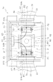
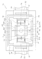
- FIG. 2 is a plan view showing a configuration inside the contact case 18 of the relay 1a.
- the positions of the movable contact piece 7 and the drive shaft 15 are indicated by two-dot lines.
- the relay 1a includes a first magnet 51, a second magnet 52, and a third magnet 53.
- the first magnet 51, the second magnet 52, and the third magnet 53 are permanent magnets for extinguishing an arc generated between the contacts.
- the first magnet 51 and the second magnet 52 are arranged apart from each other in the left-right direction.
- the first magnet 51 is arranged on one side of the movable contact piece 7 in the left-right direction.
- the second magnet 52 is arranged on one side of the movable contact piece 7 in the left-right direction.
- the first magnet 51 is arranged on the left side of the movable contact piece 7.
- the second magnet 52 is arranged on the right side of the movable contact piece 7.
- the first magnet 51 and the second magnet 52 are arranged so that the same polarity faces each other. More specifically, the first magnet 51 includes an S-pole surface 51S facing the movable contact piece 7 and an N-pole surface 51N opposite to the S-pole surface 51S.
- the second magnet 52 includes an S-pole surface 52S facing the movable contact piece 7, and an N-pole surface 52N opposite to the S-pole surface 52S.
- the third magnet 53 is arranged to face the movable contact piece 7 in the front-rear direction.
- the front-rear direction coincides with the width direction of the movable contact piece 7 that intersects the longitudinal direction of the movable contact piece 7.
- the third magnet 53 includes an N-pole surface 53N facing the movable contact piece 7 and an S-pole surface 53S opposite to the N-pole surface 53N.
- the relay 1a includes a yoke 47.
- the yoke 47 connects the first magnet 51, the second magnet 52, and the third magnet 53. Specifically, the yoke 47 is connected to the N pole surface 51N of the first magnet 51, the N pole surface 52N of the second magnet 52, and the S pole surface 53S of the third magnet 53.
- first contact position P1 a position between the first fixed contact 11 and the first movable contact 13
- second contact position P2 a position between the second fixed contact 12 and the second movable contact 14
- a magnetic flux B2 directed outward in the left-right direction is generated.
- a magnetic flux B ⁇ b> 1 in the direction from the center in the left-right direction toward the first end 7 a is generated between the first fixed contact 11 and the first movable contact 13.
- a magnetic flux B ⁇ b> 2 in the direction from the center in the left-right direction toward the second end 7 b is generated between the second fixed contact 12 and the second movable contact 14.
- the Lorentz force due to the self-magnetic field of the first fixed terminal 5 and the second fixed terminal 6 may act on the arc.
- the Lorentz force F ⁇ b> 5 inward in the left-right direction acts on the arc at the first contact point P ⁇ b> 1 due to the magnetic field due to the current flowing through the first intermediate portion 22. I do.
- the resultant force F1 'of Lorentz forces F1 and F5 acts on the arc, whereby the arc is elongated in the direction of the resultant force F1' of Lorentz force.
- the relay 1a includes the wall portion 60 for extinguishing the arc extended inward as described above.
- the wall portion 60 is disposed inside the first fixed contact 11 and the second fixed contact 12 in the left-right direction.
- the wall 60 includes a first wall 61 and a second wall 62.
- the first wall portion 61 is disposed between the first contact position P1 and the drive shaft 15 in the left-right direction.
- the first wall 61 extends in the front-rear direction.
- the second wall portion 62 is disposed between the second contact position and the drive shaft 15 in the left-right direction.
- the second wall 62 extends in the front-rear direction.
- the first wall portion 61 and the second wall portion 62 are formed of an arc extinguishing material that generates an arc extinguishing gas by the heat of the arc.
- the first wall portion 61 and the second wall portion 62 may be formed of, for example, a thermosetting resin such as an unsaturated polyester resin or a melamine resin.
- the first wall portion 61 and the second wall portion 62 may be formed of a thermoplastic resin such as a polyolefin resin, a polyamide resin, and a polyacetal resin.
- the first wall portion 61 and the second wall portion 62 may be formed of another arc extinguishing material.
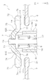
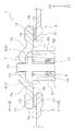
- FIGS. 4 and 5 are enlarged side sectional views of the contact device 3 and the wall portion 60.
- FIG. FIG. 4 shows the position of the movable contact piece 7 in the open state.
- FIG. 5 shows the position of the movable contact piece 7 in the closed state.
- the first wall portion 61 and the second wall portion 62 extend in the up-down direction.
- the first wall 61 faces the first fixed contact 11.
- the second wall portion 62 faces the second fixed contact 12.
- the first wall portion 61 is disposed at a position beyond the first fixed contact 11 toward the movable contact piece 7 in the moving direction of the movable contact piece 7. That is, the upper end 610 of the first wall portion 61 is disposed above the first fixed contact 11.
- the first wall portion 61 is arranged from a position below the first fixed contact 11 to a position above the first fixed contact 11.
- the second wall portion 62 faces the second fixed contact 12.
- the second wall portion 62 faces the second fixed contact 12.
- the second wall portion 62 is disposed at a position beyond the second fixed contact 12 toward the movable contact piece 7 in the moving direction of the movable contact piece 7. That is, the upper end 620 of the second wall portion 62 is disposed above the second fixed contact 12.
- the second wall portion 62 is arranged from a position below the second fixed contact 12 to a position above the second fixed contact 12.
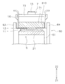
- FIG. 6 is a sectional view taken along line VI-VI in FIG. As shown in FIG. 6, in the closed state, the first wall 61 overlaps the first movable contact 13 and the first fixed contact 11 when viewed from the longitudinal direction of the movable contact piece 7.
- the second wall portion 62 faces the second fixed contact 12 and the second movable contact 14.
- the upper end 620 of the second wall portion 62 is located above the lower end of the second movable contact 14.
- the second wall portion 62 overlaps the second movable contact 14 and the second fixed contact 12 in the closed state as viewed from the longitudinal direction of the movable contact piece 7, similarly to the first wall portion 61.
- the movable contact piece 7 has a shape that avoids interference with the wall 60.
- the movable contact piece 7 has a shape depressed in a direction away from the wall 60. That is, the movable contact piece 7 has a shape that is convexly curved upward.
- the movable contact piece 7 includes a first contact support portion 71, a second contact support portion 72, an intermediate portion 73, a first bent portion 74, and a second bent portion 75.
- the first contact support 71 supports the first movable contact 13.
- the first contact support portion 71 includes the first end 7a described above.
- the second contact support part 72 supports the second movable contact 14.
- the second contact support portion 72 includes the above-described second end portion 7b.
- the intermediate portion 73 is located at the center of the movable contact piece 7 in the left-right direction.
- the contact piece holding section 8 is attached to the intermediate section 73.
- the drive shaft 15 is attached to the intermediate portion 73.
- the intermediate portion 73 is located above the first contact support 71 and the second contact support 72.
- the first bent part 74 is located between the first contact support part 71 and the intermediate part 73.
- the first bent portion 74 has a shape curved in a direction away from the first wall portion 61. That is, the first bent portion 74 has a shape curved upward from the first contact support portion 71.
- the first bent portion 74 is arranged to face the first wall 61.
- the second bent portion 75 is located between the second contact support portion 72 and the intermediate portion 73.
- the second bent portion 75 has a shape curved in a direction away from the second wall portion 62. That is, the second bent portion 75 has a shape curved upward from the second contact support portion 72.
- the second bent portion 75 is arranged to face the second wall portion 62.
- the upper end 610 of the first wall portion 61 is located above the bottom surface of the first contact support portion 71.
- the upper end 620 of the second wall portion 62 is located above the bottom surface of the second contact support portion 72.
- a connection point 76 between the first bent part 74 and the first contact support part 71 is located outside the first wall part 61.
- a connection point 77 between the second bent portion 75 and the second contact support portion 72 is located outside the second wall portion 62.
- the connection point 76 between the first bent portion 74 and the first contact support portion 71 is located below the upper end 610 of the first wall portion 61.
- the connection point 77 between the second bent portion 75 and the second contact support portion 72 is located below the upper end 620 of the second wall portion 62.
- the wall portion 60 further includes a third wall portion 63 and a fourth wall portion 64.
- the third wall portion 63 and the fourth wall portion 64 are arranged apart from each other in the front-rear direction.
- the contact piece support 8 is disposed between the third wall 63 and the fourth wall 64.
- the holder 16 is disposed between the third wall 63 and the fourth wall 64. The holder 16 is prevented from rotating by the third wall 63 and the fourth wall 64.
- the first wall portion 61 and the second wall portion 62 make the first fixed contact 11 and the second fixed contact 12 move in the moving direction of the movable contact piece 7. It is arranged at a position beyond the seventh side. Therefore, when the arc is extended toward the inside of the first fixed contact 11 and the second fixed contact 12, the arc easily hits the first wall 61 and the second wall 62. Thereby, the arc can be extinguished quickly.
- the movable contact piece 7 In the closed state, the movable contact piece 7 has a curved shape so as not to interfere with the first wall 61 and the second wall 62. Therefore, even if the first wall portion 61 and the second wall portion 62 are arranged as described above, interference between the movable contact piece 7 and the first wall portion 61 and the second wall portion 62 can be avoided. .
- the movable contact piece 7 includes a first bent portion 74 and a second bent portion 75. With such a shape of the movable contact piece 7, interference with the first wall portion 61 and the second wall portion 62 can be avoided. Further, the starting point of the arc can be limited to the first bent portion 74 and the second bent portion 75. This makes it easier for the arc extended from the first bent portion 74 to hit the first wall 61. Further, the arc extended from the second bent portion 75 easily hits the second wall portion 62. Thereby, the arc can be extinguished more quickly.
- the first wall portion 61 overlaps the first movable contact 13 when viewed from the longitudinal direction of the movable contact piece 7.
- the second wall portion 62 overlaps the second movable contact 14 when viewed from the longitudinal direction of the movable contact piece 7. Therefore, the arc easily hits the first wall 61 and the second wall 62. Thereby, the arc can be extinguished more quickly.
- FIG. 7 is a plan view showing the configuration inside the contact case 18 of the relay 1b according to the second embodiment.
- the first magnet 51 and the second magnet 52 are arranged such that different poles face each other.
- An S-pole surface 51S of the first magnet 51 is arranged to face the movable contact piece 7, and an N-pole surface 52N of the second magnet 52 is arranged to face the movable contact piece 7.
- the third magnet 53 of the first embodiment is omitted.
- Other configurations of the relay 1b according to the second embodiment are the same as those of the relay 1a according to the first embodiment.
- a magnetic flux B11 directed to the left is generated at the first contact position P1 and the second contact position P2. Therefore, when a current flows from the left to the right in the movable contact piece 7, a Lorentz force acts in the front-rear direction as indicated by arrows F11 and F12.
- Lorentz force due to the self-magnetic field of the first fixed terminal 5 and the second fixed terminal 6 acts on the arc.
- the Lorentz force F15 inward in the left-right direction acts on the arc at the first contact point P1 due to the magnetic field due to the current flowing through the first intermediate portion 22. I do.
- the resultant force F11 'of Lorentz forces F11 and F15 acts on the arc, whereby the arc is elongated in the direction of the resultant force F11' of Lorentz force.
- FIG. 8 is a plan view showing the configuration inside the contact case 18 of the relay 1c according to the third embodiment.
- the first magnet 51 and the second magnet 52 are arranged apart in the front-rear direction.
- the first magnet 51 and the second magnet 52 are arranged such that different poles face each other. More specifically, the S pole surface 51S of the first magnet 51 is arranged to face the movable contact piece 7, and the N pole surface 52N of the second magnet 52 is arranged to face the movable contact piece 7.
- Other configurations of the relay 1c according to the third embodiment are the same as those of the relay 1a according to the first embodiment.
- a magnetic flux B21 along the front-rear direction is generated at the first contact position P1 and the second contact position P2. Therefore, when a current flows from the left to the right in the movable contact piece 7, a Lorentz force acts inward in the left-right direction as indicated by arrows F21 and F22. Therefore, in the relay 1c according to the third embodiment, the arc is extended inward even when the Lorentz force due to the self-magnetic field of the first fixed terminal 5 and the second fixed terminal 6 does not occur. Therefore, even without the first intermediate portion 22 and the second intermediate portion 32, the arc is stretched inward. Even in such a case, in the relay 1c according to the third embodiment, as in the relay 1a according to the first embodiment, the arc is quickly extinguished by the first wall 61 and the second wall 62. can do.
- FIG. 9A is a plan view illustrating a configuration inside a contact case 18 of a relay 1d according to the fourth embodiment.
- FIG. 9B is a side view showing the configuration inside the contact case 18 of the relay 1d according to the fourth embodiment.
- the movable contact piece 7 includes a first hole 81 and a second hole 82.
- the first hole 81 and the second hole 82 penetrate the movable contact piece 7 in the up-down direction.
- the first hole 81 is arranged to face the first wall 61 in the up-down direction.
- the second hole 82 is arranged to face the second wall 62 in the up-down direction.
- the first hole 81 is arranged above the first wall 61.
- the second hole 82 is arranged above the second wall 62.
- the first hole 81 has a size that allows the first wall portion 61 to be inserted.
- the second hole 82 has a size that allows the second wall 62 to be inserted.
- the first wall 61 is disposed in the first hole 81, and the second wall 62 is disposed in the second hole 82.
- the first wall portion 61 may be disposed in the first hole 81 and the second wall portion 62 may be disposed in the second hole 82 not only in the closed state but also in the open state.
- FIG. 10A is a plan view showing a configuration inside a contact case 18 of a relay 1e according to the fifth embodiment.
- FIG. 10B is a side view showing the configuration inside the contact case 18 of the relay 1e according to the fifth embodiment.
- the movable contact piece 7 includes a first recess 83 and a second recess 84.
- the first recess 83 and the second recess 84 have a shape recessed upward from the bottom surface of the movable contact piece 7.
- the first concave portion 83 is arranged to face the first wall portion 61 in the vertical direction.
- the second concave portion 84 is arranged to face the second wall portion 62 in the vertical direction.
- the first recess 83 is arranged above the first wall 61.
- the second recess 84 is arranged above the second wall 62.
- the first concave portion 83 has a size that allows the upper end 610 of the first wall portion 61 to be inserted.
- the second concave portion 84 has a size that allows the upper end 620 of the second wall portion 62 to be inserted.
- the first wall 61 is disposed in the first recess 83, and the second wall 62 is disposed in the second recess 84.
- the first wall 61 may be arranged in the first recess 83 and the second wall 62 may be arranged in the second recess 84.
- FIG. 11 is a side view showing the configuration inside the contact case 18 of the relay 1f according to the sixth embodiment.
- the movable contact piece 7 includes a first contact support portion 91, a second contact support portion 92, an intermediate portion 93, a first bent portion 94, and a second bent portion 95.
- the first contact support section 91 supports the first movable contact 13.
- the second contact support section 92 supports the second movable contact 14.
- the first bent portion 94 has a shape bent upward from the first contact support portion 91.
- the first bent portion 94 is located outside the first contact support portion 91 in the left-right direction.
- the second bent portion 95 has a shape bent upward from the second contact support portion 92.
- the second bent portion 95 is located outside the second contact support portion 92 in the left-right direction.
- the intermediate portion 93 is located between the first bent portion 94 and the second bent portion 95.
- the intermediate section 93 is located above the first contact support section 91 and the second contact support section 92.
- the inner end 910 of the first contact support 91 and the inner end 920 of the second contact support 92 are arranged apart from each other.
- the first wall portion 61 and the second wall portion 62 are arranged to face a space between the inner end 910 of the first contact support 91 and the inner end 920 of the second contact support 92.
- the first wall 61 and the second wall 62 are arranged between the inner end 910 of the first contact support 91 and the inner end 920 of the second contact support 92.
- the first wall 61 and the second wall 62 are provided between the inner end 910 of the first contact support 91 and the inner end 920 of the second contact support 92. May be arranged.
- the drive device 4 pulls the drive shaft 15 from the coil 41 side, and the movable contact piece 7 moves in the contact direction Z1.
- the driving device 4 pushes out the driving shaft 15 from the coil 41 side
- the movable contact piece 7 moves in the separating direction Z2.
- the operation direction of the drive shaft 15 for opening and closing the contacts may be opposite to the above embodiment. That is, the movable contact piece 7 may be moved in the separating direction Z2 by the drive device 4 pulling the drive shaft 15 toward the coil 41 side.
- the movable contact piece 7 may move in the contact direction Z1 by the drive device 4 pushing the drive shaft 15 from the coil 41 side. That is, the contact direction Z1 and the separation direction Z2 may be upside down in the above embodiment.
- FIG. 12 is a side view showing the configuration inside the contact case 18 of the relay 1g according to the seventh embodiment.
- the movable contact piece 7 is arranged below the first fixed contact 11 and the second fixed contact 12.
- the first movable contact 13 and the second movable contact 14 come into contact with the first fixed contact 11 and the second fixed contact 12.
- the first movable contact 13 and the second movable contact 14 are separated from the first fixed contact 11 and the second fixed contact 12 by moving the movable contact piece 7 downward, that is, in the separating direction Z2.
- the first wall 61 and the second wall 62 are arranged.
- the lower end 611 of the first wall 61 and the lower end 621 of the second wall 62 face the movable contact piece 7.
- the movable contact piece 7 has a curved shape so as to avoid interference with the first wall portion 61 and the second wall portion 62.
- the movable contact piece 7 may have the same shape as the movable contact piece 7 of the relays 1d to 1f according to the fourth to sixth embodiments.
- the present invention is not limited to the above embodiment, and various modifications can be made without departing from the gist of the invention.
- the configuration of the driving device 4 may be changed.
- the shape or arrangement of the coil 41, the spool 42, the iron core 43, the return spring 44, or the yoke 45 may be changed.
- the shape or arrangement of the case 2 may be changed.
- the shape or arrangement of the first fixed terminal 5, the second fixed terminal 6, and the movable contact piece 7 may be changed.
- the first external connection part 24 and the second external connection part 34 may protrude upward from the case 2.
- the first external connection portion 24 and the second external connection portion 34 may protrude from the case 2 in the front-rear direction.
- the first fixed contact 11 may be separate from the first fixed terminal 5 or may be integrated with the first fixed terminal 5.
- the second fixed contact 12 may be separate from or integral with the second fixed terminal 6.
- the first movable contact 13 may be separate from the movable contact piece 7 or may be integrated.
- the second movable contact 14 may be separate from the movable contact piece 7 or may be integrated.
- the shape or arrangement of the wall 60 may be changed.
- the shape or arrangement of the first to fourth wall portions 61-64 may be changed.
- the third wall portion 63 and the fourth wall portion 64 may be omitted.
Landscapes
- Physics & Mathematics (AREA)
- Electromagnetism (AREA)
- Arc-Extinguishing Devices That Are Switches (AREA)
- Contacts (AREA)
Abstract
壁部(60)は、長手方向において第1固定接点(11)及び第2固定接点(12)の内側に配置される。壁部(60)の少なくとも一部は、可動接触片(7)の移動方向において、第1固定接点(11)及び第2固定接点(12)を可動接触片(7)側に越えた位置に配置されている。可動接触片(7)は、第1可動接点(13)及び第2可動接点(14)が第1固定接点(11)及び第2固定接点(12)に接触している状態で壁部(60)を避けた形状を有する。
Description
本発明はリレーに関する。
リレーには、接点に発生するアークを消弧するための構造を備えるものがある。例えば,特許文献1では、固定接点部の内側に壁部が配置されている。固定接点部は、固定接点接触部と、固定接点接触部が固定された固定接点台座部とを含む。壁部の高さは、固定接点台座部よりも高く、固定接点接触部の高さよりも低い。
特許文献1では、上記の壁部によって、アーク電流の沿面距離が大きくなる。それにより、アーク電流が短絡し難くなる。また、壁部が上記のような高さであることで、可動接点部の動作を阻害することが防止される。
特許文献1では、可動接点部との干渉を避けるため、壁部を高くすることができない。そのため、壁部によるアークの遮断性能を向上させることは困難である。
本発明の課題は、リレーにおいて、可動接触片の動作を阻害することを回避しながら、アークの遮断性能を向上させることにある。
一態様に係るリレーは、可動接触片と、第1固定端子と、第2固定端子と、駆動装置と、壁部とを含む。可動接触片は、可動接触片の長手方向に互いに離れて配置された第1可動接点と第2可動接点とを含む。第1固定端子は、第1可動接点に対向して配置された第1固定接点を含む。第2固定端子は、第2可動接点に対向して配置された第2固定接点を含む。駆動装置は、第1可動接点及び第2可動接点が第1固定接点及び第2固定接点に対して接触する方向及び開離する方向に可動接触片を移動させる。壁部は、長手方向において第1固定接点及び第2固定接点の内側に配置される。壁部の少なくとも一部は、可動接触片の移動方向において、第1固定接点及び第2固定接点を可動接触片側に越えた位置に配置されている。可動接触片は、第1可動接点及び第2可動接点が第1固定接点及び第2固定接点に接触している状態で壁部を避けた形状を有する。
本態様に係るリレーでは、壁部の少なくとも一部は、可動接触片の移動方向において、第1固定接点及び第2固定接点を可動接触片側に越えた位置に配置されている。そのため、アークが第1固定接点及び第2固定接点の内側へ向かって引き伸ばされた場合に、壁部に当たり易い。それにより、迅速にアークを消弧することができる。また、可動接触片は、第1可動接点及び第2可動接点が第1固定接点及び第2固定接点に接触している状態で壁部を避けた形状を有する。そのため、上記のように壁部が配置されても、可動接触片と壁部との干渉を回避することができる。
壁部は、アークの熱により消弧ガスを発生させる消弧材で形成されてもよい。この場合、壁部から消弧ガスを発生させることで、より迅速にアークを消弧することができる。
可動接触片は、壁部から離れる方向に凹んだ形状を有してもよい。この場合、可動接触片の凹んだ形状により、壁部との干渉を回避することができる。
可動接触片は、壁部から離れる方向に湾曲した曲げ部を含んでもよい。この場合、可動接触片の曲げ部の形状により、壁部との干渉を回避することができる。また、アークの起点を曲げ部に限定することができる。
曲げ部は、壁部に対向して配置されてもよい。この場合、曲げ部から引き伸ばされたアークが壁部に当たり易くなる。それにより、より迅速にアークを消弧することができる。
可動接触片は、壁部に対向して配置された孔を含んでもよい。この場合、第1可動接点及び第2可動接点が第1固定接点及び第2固定接点に接触している状態で、壁部が孔内に配置されることで、壁部との干渉を回避することができる。
可動接触片は、壁部に対向して配置された凹部を含んでもよい。この場合、第1可動接点及び第2可動接点が第1固定接点及び第2固定接点に接触している状態で、壁部が凹部内に配置されることで、壁部との干渉を回避することができる。
可動接触片は、第1接点支持部と第2接点支持部とを含んでもよい。第1接点支持部は、第1可動接点を支持してもよい。第2接点支持部は、第2可動接点を支持してもよい。可動接触片の長手方向において、第1接点支持部の内端部と第2接点支持部の内端部とは互いに離れて配置されてもよい。壁部は、第1接点支持部の内端部と第2接点支持部の内端部との間の空間に対向して配置されてもよい。この場合、第1可動接点及び第2可動接点が第1固定接点及び第2固定接点に接触している状態で、壁部が第1接点支持部の内端部と第2接点支持部の内端部との間に配置されることで、壁部との干渉を回避することができる。
第1可動接点及び第2可動接点が第1固定接点及び第2固定接点に接触している状態で、可動接触片の長手方向から見て、壁部は第1可動接点及び第1固定接点と重なってもよい。この場合、アークが壁部に当たり易くなる。それにより、より迅速にアークを消弧することができる。
第1固定端子は、接点支持部と中間部とを含んでもよい。接点支持部は、第1固定接点を支持し、長手方向において第1固定接点から外側へ延びてもよい。中間部は、接点支持部から可動接触片の移動方向と平行な方向に延びてもよい。この場合、中間部を流れる電流により、第1固定接点及び第2固定接点の内側へ向かう方向へのローレンツ力がアークに作用し易い。しかし、アークが第1固定接点及び第2固定接点の内側へ向かって引き伸ばされても、壁部によって迅速にアークを消弧することができる。
本発明によれば、リレーにおいて可動接触片の動作を阻害することを回避しながら、アークの遮断性能を向上させることができる。
以下、図面を参照して実施形態に係るリレーについて説明する。図1は第1実施形態に係るリレー1aを示す側面断面図である。図1に示すように、リレー1aは、ケース2と、接点装置3と、駆動装置4とを備える。なお、以下の説明において、上下左右の各方向は、図1における上下左右の各方向を意味するものとする。また、前後方向は、図1の紙面に垂直な方向を意味するものとする。ただし、これらの方向の定義は、リレー1aの配置方向を限定するものではない。
ケース2は、接点装置3と駆動装置4とを収容している。ケース2は、絶縁性を有する樹脂で形成されている。ケース2は、ケース本体2aと蓋部2bとを含む。接点装置3と駆動装置4とは、ケース本体2a内に配置されている。蓋部2bは、ケース本体2aと別体である。蓋部2bは、ケース本体2aに取り付けられている。ケース本体2aは、接点ケース18とアウターケース19とを含む。接点ケース18は、ケース2の内部を第1収納部S1と第2収納部S2とに区画している。第1収納部S1内には、接点装置3が配置される。第2収納部S2内には、駆動装置4が配置される。アウターケース19は、接点ケース18を内部に収容している。
接点装置3は、第1固定端子5と、第2固定端子6と、可動接触片7と、接触片保持部8とを含む。第1固定端子5と、第2固定端子6と、可動接触片7とは、例えば銅などの導電性を有する材料で形成されている。第1固定端子5は、第1固定接点11を含む。第2固定端子6は、第2固定接点12を含む。第1固定接点11と第2固定接点12とは、左右方向に離れて配置されている。
可動接触片7は、左右方向に延びている。本実施形態において、可動接触片7の長手方向は、左右方向に一致する。可動接触片7は、第1可動接点13と第2可動接点14とを含む。第1可動接点13と第2可動接点14とは、左右方向に離れて配置されている。第1可動接点13は、第1固定接点11に対向して配置されている。第2可動接点14は、第2固定接点12に対向して配置されている。
可動接触片7は、第1端部7aと第2端部7bとを含む。第1端部7aは、左右方向における可動接触片7の一方の端部である。第2端部7bは、左右方向における可動接触片7の他方の端部である。本実施形態では、第1端部7aは、可動接触片7の左方の端部である。第2端部7bは、可動接触片7の右方の端部である。第1可動接点13は、左右方向における可動接触片7の中央と第1端部7aとの間に配置される。第2可動接点14は、左右方向における可動接触片7の中央と第2端部7bとの間に配置される。
可動接触片7は、上下方向に移動可能に配置されている。詳細には、可動接触片7は、接触方向Z1と開離方向Z2とに移動可能に配置されている。接触方向Z1は、第1可動接点13及び第2可動接点14が第1固定接点11及び第2固定接点12に対して接触する方向(図1における下方)である。開離方向Z2は、第1可動接点13及び第2可動接点14が第1固定接点11及び第2固定接点12から開離する方向(図1における上方)である。
接触片保持部8は、可動接触片7を保持している。接触片保持部8は、可動接触片7において左右方向の中央で可動接触片7を保持している。従って、接触片保持部8は、左右方向において第1可動接点13と第2可動接点14との間の位置において可動接触片7を保持している。
接触片保持部8は、駆動軸15と、ホルダ16と、接点バネ17とを含む。駆動軸15は、上下方向に延びている。駆動軸15は、可動接触片7と駆動装置4とを接続している。駆動軸15は、接触方向Z1及び開離方向Z2に移動可能に配置されている。ホルダ16は、可動接触片7に接続されており、可動接触片7を保持している。接点バネ17は、駆動軸15とホルダ16との間に配置されている。駆動軸15は、接点バネ17を介して、ホルダ16に接続されている。
第1固定端子5は、第1接点支持部21と、第1中間部22と、第1外部接続部24とを含む。第1接点支持部21は、ケース2内において、第1固定接点11を支持している。第1接点支持部21は、左右方向において、第1固定接点11から外側へ延びる。なお、左右方向において外側とは、左右方向において駆動軸15の中心軸線から離れる方向を意味する。左右方向において内側とは、左右方向において駆動軸15の中心軸線に近づく方向を意味する。
第1中間部22は、第1接点支持部21と第1外部接続部24との間に位置する。第1中間部22は、第1接点支持部から、可動接触片7の移動方向に平行な方向、すなわち上下方向に延びている。詳細には、第1中間部22は、第1接点支持部21から上方に延びている。第1外部接続部24は、第1中間部22から左方に延びている。第1外部接続部24は、ケース2の外側に突出している。
第1固定端子5は、第1接点支持部21と第1中間部22との間、及び、第1中間部22と第1外部接続部24との間で屈曲した形状を有している。第1接点支持部21と第1中間部22と第1外部接続部24とは、一体的に形成されてもよい。或いは、第1接点支持部21と第1中間部22と第1外部接続部24とは、互いに別体であり、溶接等の固定手段によって互いに接続されてもよい。
第2固定端子6は、第2接点支持部31と、第2中間部32と、第2外部接続部34とを含む。第2接点支持部31は、ケース2内において、第2固定接点12を支持している。第2固定端子6は、第1固定端子5と左右対称な形状を有している。第2接点支持部31と、第2中間部32と、第2外部接続部34とは、それぞれ第1接点支持部21と、第1中間部22と、第1外部接続部24とに対応している。従って、第2固定端子6については詳細な説明を省略する。
駆動装置4は、可動接触片7を動作させる駆動力を発生させる。駆動装置4は、電磁力によって可動接触片7を動作させる。駆動装置4は、接触方向Z1及び開離方向Z2に可動接触片7を移動させる。駆動装置4は、可動接触片7の下方に配置されている。駆動装置4は、コイル41と、スプール42と、鉄心43と、復帰バネ44と、ヨーク45とを含む。
コイル41は、スプール42に巻回されている。コイル41及びスプール42は、駆動軸15と同軸に配置されている。スプール42は、スプール42の軸線方向に貫通する孔42aを含む。鉄心43と復帰バネ44とは、スプール42の孔42aに挿入されている。ヨーク45は、鉄心43に接続されている。
ヨーク45は、第1ヨーク45aと第2ヨーク45bとを含む。第1ヨーク45aは、接点装置3とスプール42との間に配置されている。第2ヨーク45bは、第1ヨーク45aに接続されている。第2ヨーク45bは、U字状の形状を有している。第2ヨーク45bは、コイル41の両側方と、コイル41に対して第1ヨーク45aの反対側とに配置されている。
鉄心43は、固定鉄心43aと可動鉄心43bとリング鉄心43cとを含む。固定鉄心43aは、第2ヨーク45bに固定されている。リング鉄心43cは、第1ヨーク45aに接触している。可動鉄心43bは、固定鉄心43a及びリング鉄心43cと別体である。可動鉄心43bは、接触方向Z1及び開離方向Z2に移動可能に配置されている。可動鉄心43bは、リング鉄心43c内で移動する。可動鉄心43bは、駆動軸15に接続されている。復帰バネ44は、可動鉄心43bと固定鉄心43aとの間に配置されている。復帰バネ44は、可動鉄心43bを開離方向Z2に付勢している。
次に、リレー1aの動作について説明する。コイル41に電流が流されず励磁されていないときには、可動鉄心43bと共に、駆動軸15は、復帰バネ44の弾性力によって開離方向Z2に押圧されている。そのため、可動接触片7も開離方向Z2に押圧されており、図1に示すように、第1可動接点13及び第2可動接点14は、第1固定接点11及び第2固定接点12から開離した開状態となっている。
コイル41に電流が流されて励磁されると、コイル41の電磁力により、可動鉄心43bが、復帰バネ44の弾性力に抗して、接触方向Z1に移動する。それにより、駆動軸15とホルダ16と可動接触片7とが共に接触方向Z1に移動して、第1可動接点13及び第2可動接点14が、第1固定接点11及び第2固定接点12に接触した閉状態となる。
コイル41への電流が停止され消磁されると、可動鉄心43bと共に、駆動軸15は、復帰バネ44の弾性力によって開離方向Z2に押圧される。そのため、可動接触片7も開離方向Z2に押圧されることで、第1可動接点13及び第2可動接点14は、開状態に戻る。
図2は、リレー1aの接点ケース18内の構成を示す平面図である。図2では、可動接触片7及び駆動軸15の位置が二点差線で示されている。図1及び図2に示すように、リレー1aは、第1磁石51と第2磁石52と第3磁石53とを含む。第1磁石51と第2磁石52と第3磁石53とは、接点間で生じたアークを消弧するための永久磁石である。
第1磁石51と第2磁石52とは、左右方向に互いに離れて配置されている。第1磁石51は、左右方向において可動接触片7の一側方に配置されている。第2磁石52は、左右方向において可動接触片7の一側方に配置されている。詳細には、第1磁石51は、可動接触片7の左方に配置されている。第2磁石52は、可動接触片7の右方に配置されている。
第1磁石51と第2磁石52とは、互いに同極が向き合うように配置されている。詳細には、第1磁石51は、可動接触片7に対向するS極面51Sと、S極面51Sの反対側のN極面51Nとを含む。第2磁石52は、可動接触片7に対向するS極面52Sと、S極面52Sの反対側のN極面52Nとを含む。
第3磁石53は、可動接触片7に対して前後方向に対向して配置されている。なお、本実施形態において、前後方向は、可動接触片7の長手方向と交差する可動接触片7の幅方向と一致する。第3磁石53は、可動接触片7に対向するN極面53Nと、N極面53Nの反対側のS極面53Sとを含む。
また、リレー1aは、ヨーク47を含む。ヨーク47は、第1磁石51と第2磁石52と第3磁石53とを接続している。詳細には、ヨーク47は、第1磁石51のN極面51Nと、第2磁石52のN極面52Nと、第3磁石53のS極面53Sとに接続されている。
以上のような第1磁石51と、第2磁石52と、第3磁石53との配置により、図2に示すように、第1固定接点11と第1可動接点13との間の位置(以下、「第1接点位置P1」と呼ぶ)において左右方向外側に向かう磁束B1が生成される。また、第2固定接点12と第2可動接点14との間の位置(以下、「第2接点位置P2」と呼ぶ)において左右方向外側に向かう磁束B2が生成される。詳細には、左右方向における中央から第1端部7aに向かう方向への磁束B1が、第1固定接点11と第1可動接点13との間において生成される。左右方向における中央から第2端部7bに向かう方向への磁束B2が、第2固定接点12と第2可動接点14との間において生成される。
従って、可動接触片7において左方から右方に電流が流れるときには、図2において矢印F1及び矢印F2で示すように前後方向にローレンツ力が作用する。また、可動接触片7において右方から左方に電流が流れるときには、図2において矢印F3及び矢印F4で示すように前後方向にローレンツ力が作用する。それにより、アークが矢印F1-F4で示す方向に引き伸ばされ、アークを迅速に消弧することができる。
ただし、図3に示すように、アークには、第1固定端子5及び第2固定端子6の自己磁界によるローレンツ力が作用する場合がある。例えば、可動接触片7において左方から右方に電流が流れるときには、第1接点位置P1では、第1中間部22を流れる電流による磁界によって、左右方向における内側へ向かうローレンツ力F5がアークに作用する。この場合、アークには、ローレンツ力F1,F5の合力F1’が作用し、それにより、アークは、ローレンツ力の合力F1’の方向に引き伸ばされる。
同様に、可動接触片7において左方から右方に電流が流れるときには、第2接点位置P2では、第2中間部32を流れる電流による磁界によって、左右方向における内側へ向かうローレンツ力F6が、アークに作用する。この場合、アークには、ローレンツ力F2,F6の合力F2’が作用し、それにより、アークは、ローレンツ力の合力F2’の方向に引き伸ばされる。
本実施形態に係るリレー1aは、上記のように内側へ向かって引き伸ばされたアークを消弧するための壁部60を備えている。壁部60は、左右方向において第1固定接点11及び第2固定接点12の内側に配置されている。壁部60は、第1壁部61と第2壁部62とを含む。第1壁部61は、左右方向において第1接点位置P1と駆動軸15との間に配置されている。第1壁部61は、前後方向に延びている。第2壁部62は、左右方向において第2接点位置と駆動軸15との間に配置されている。第2壁部62は、前後方向に延びている。
第1壁部61と第2壁部62とは、アークの熱により消弧ガスを発生させる消弧材で形成されている。第1壁部61と第2壁部62とは、例えば、不飽和ポリエステル樹脂、メラミン樹脂などの熱硬化性樹脂で形成されてもよい。或いは、第1壁部61と第2壁部62とは、ポリオレフィン樹脂、ポリアミド樹脂、ポリアセタール樹脂などの熱可塑性樹脂などで形成されてもよい。或いは、第1壁部61と第2壁部62とは、他の消弧材で形成されてもよい。
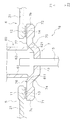
図4及び図5は、接点装置3及び壁部60の拡大側面断面図である。図4は、開状態での可動接触片7の位置を示している。図5は、閉状態での可動接触片7の位置を示している。図4及び図5に示すように、第1壁部61と第2壁部62とは、上下方向に延びている。第1壁部61は、第1固定接点11と対向している。第2壁部62は、第2固定接点12と対向している。第1壁部61は、可動接触片7の移動方向において第1固定接点11を可動接触片7側に越えた位置に配置されている。すなわち、第1壁部61の上端610は、第1固定接点11よりも上方に配置されている。第1壁部61は、第1固定接点11よりも下方の位置から第1固定接点11よりも上方の位置まで配置されている。
第2壁部62は、第2固定接点12と対向している。第2壁部62は、第2固定接点12と対向している。第2壁部62は、可動接触片7の移動方向において第2固定接点12を可動接触片7側に越えた位置に配置されている。すなわち、第2壁部62の上端620は、第2固定接点12よりも上方に配置されている。第2壁部62は、第2固定接点12よりも下方の位置から第2固定接点12よりも上方の位置まで配置されている。
図5に示すように、閉状態で、第1壁部61は、第1固定接点11及び第1可動接点と対向している。閉状態で、第1壁部61の上端610は、第1可動接点13の下端よりも上方に位置する。図6は、図5におけるVI-VI断面図である。図6に示すように、閉状態で、可動接触片7の長手方向から見て、第1壁部61は第1可動接点13及び第1固定接点11と重なる。
図4に示すように、閉状態で、第2壁部62は、第2固定接点12及び第2可動接点14と対向している。閉状態で、第2壁部62の上端620は、第2可動接点14の下端よりも上方に位置する。図示を省略するが第1壁部61と同様に、閉状態で、可動接触片7の長手方向から見て、第2壁部62は第2可動接点14及び第2固定接点12と重なる。
図4及び図5に示すように、可動接触片7は、壁部60との干渉を避けた形状を有する。可動接触片7は、壁部60から離れる方向に凹んだ形状を有する。すなわち、可動接触片7は、上方に向かって凸に湾曲した形状を有している。詳細には、可動接触片7は、第1接点支持部71と、第2接点支持部72と、中間部73と、第1曲げ部74と、第2曲げ部75とを含む。
第1接点支持部71は、第1可動接点13を支持している。第1接点支持部71は、上述した第1端部7aを含む。第2接点支持部72は、第2可動接点14を支持している。第2接点支持部72は、上述した第2端部7bを含む。中間部73は、可動接触片7の左右方向における中央に位置する。中間部73には接触片保持部8が取り付けられる。中間部73には、駆動軸15が取り付けられる。中間部73は、第1接点支持部71及び第2接点支持部72よりも上方に位置する。
第1曲げ部74は、第1接点支持部71と中間部73との間に位置する。第1曲げ部74は、第1壁部61から離れる方向に湾曲した形状を有している。すなわち、第1曲げ部74は、第1接点支持部71から上方に向かって湾曲した形状を有している。第1曲げ部74は、第1壁部61に対向して配置されている。
第2曲げ部75は、第2接点支持部72と中間部73との間に位置する。第2曲げ部75は、第2壁部62から離れる方向に湾曲した形状を有している。すなわち、第2曲げ部75は、第2接点支持部72から上方に向かって湾曲した形状を有している。第2曲げ部75は、第2壁部62に対向して配置されている。
図5に示すように、閉状態で、第1壁部61の上端610は、第1接点支持部71の底面よりも上方に位置する。閉状態で、第2壁部62の上端620は、第2接点支持部72の底面よりも上方に位置する。第1曲げ部74と第1接点支持部71との接続点76は、第1壁部61の外側に位置する。第2曲げ部75と第2接点支持部72との接続点77は、第2壁部62の外側に位置する。閉状態で、第1曲げ部74と第1接点支持部71との接続点76は、第1壁部61の上端610よりも下方に位置する。閉状態で、第2曲げ部75と第2接点支持部72との接続点77は、第2壁部62の上端620よりも下方に位置する。
図2に示すように、壁部60は、第3壁部63と第4壁部64とをさらに含む。第3壁部63と第4壁部64とは、前後方向に互いに離れて配置される。第3壁部63と第4壁部64との間には、接触片支持部8が配置される。詳細には、第3壁部63と第4壁部64との間には、ホルダ16が配置される。第3壁部63と第4壁部64とによってホルダ16が回り止めされる。
以上説明した第1実施形態に係るリレー1aでは、第1壁部61及び第2壁部62は、可動接触片7の移動方向において、第1固定接点11及び第2固定接点12を可動接触片7側に越えた位置に配置されている。そのため、アークが第1固定接点11及び第2固定接点12の内側へ向かって引き伸ばされた場合に、アークが第1壁部61及び第2壁部62に当たり易い。それにより、迅速にアークを消弧することができる。
また、閉状態で、可動接触片7は、第1壁部61及び第2壁部62と干渉しないように湾曲した形状を有している。そのため、上記のように第1壁部61と第2壁部62とが配置されても、可動接触片7と、第1壁部61及び第2壁部62との干渉を回避することができる。
可動接触片7は、第1曲げ部74と第2曲げ部75とを含む。このような可動接触片7の形状により、第1壁部61及び第2壁部62との干渉を回避することができる。また、アークの起点を第1曲げ部74及び第2曲げ部75に限定することができる。それにより、第1曲げ部74から引き伸ばされたアークが第1壁部61に当たり易くなる。また、第2曲げ部75から引き伸ばされたアークが第2壁部62に当たり易くなる。それにより、より迅速にアークを消弧することができる。
閉状態で、可動接触片7の長手方向から見て、第1壁部61は第1可動接点13と重なる。また、閉状態で、可動接触片7の長手方向から見て、第2壁部62は第2可動接点14と重なる。そのため、アークが第1壁部61及び第2壁部62に当たり易くなる。それにより、より迅速にアークを消弧することができる。
以上、第1実施形態に係るリレー1aについて説明したが、第1~第3磁石51-53の配置、或いは極性は、上記の第1実施形態のものに限らず変更されてもよい。例えば、図7は、第2実施形態に係るリレー1bの接点ケース18内の構成を示す平面図である。
第2実施形態に係るリレー1bでは、第1磁石51と第2磁石52とは、異極同士が対向するように配置されている。第1磁石51のS極面51Sが可動接触片7と対向して配置され、第2磁石52のN極面52Nが可動接触片7と対向して配置されている。第2実施形態に係るリレー1bでは、第1実施形態の第3磁石53は省略されている。第2実施形態に係るリレー1bの他の構成は、第1実施形態に係るリレー1aと同様である。
第2実施形態に係るリレー1bでは、第1接点位置P1と第2接点位置P2とにおいて左方に向かう磁束B11が生成される。従って、可動接触片7において左方から右方に電流が流れるときには、矢印F11及び矢印F12で示すように前後方向にローレンツ力が作用する。
また、アークには、第1固定端子5及び第2固定端子6の自己磁界によるローレンツ力が作用する場合がある。例えば、可動接触片7において左方から右方に電流が流れるときには、第1接点位置P1では、第1中間部22を流れる電流による磁界によって、左右方向における内側へ向かうローレンツ力F15がアークに作用する。この場合、アークには、ローレンツ力F11,F15の合力F11’が作用し、それにより、アークは、ローレンツ力の合力F11’の方向に引き伸ばされる。
同様に、可動接触片7において左方から右方に電流が流れるときには、第2接点位置P2では、第2中間部32を流れる電流による磁界によって、左右方向における内側へ向かうローレンツ力F16が、アークに作用する。この場合、アークには、ローレンツ力F12,F16の合力F12’が作用し、それにより、アークは、ローレンツ力の合力F12’の方向に引き伸ばされる。このような場合であっても、第2実施形態に係るリレー1bでは、第1実施形態に係るリレー1aと同様に、第1壁部61及び第2壁部62によって、アークを迅速に消弧することができる。
図8は、第3実施形態に係るリレー1cの接点ケース18内の構成を示す平面図である。第3実施形態に係るリレー1cでは、第1磁石51と第2磁石52とは、前後方向に離れて配置されている。第1磁石51と第2磁石52とは、異極同士が対向するように配置されている。詳細には、第1磁石51のS極面51Sが可動接触片7と対向して配置され、第2磁石52のN極面52Nが可動接触片7と対向して配置されている。第3実施形態に係るリレー1cの他の構成は、第1実施形態に係るリレー1aと同様である。
第3実施形態に係るリレー1cでは、第1接点位置P1と第2接点位置P2とにおいて前後方向に沿う磁束B21が生成される。従って、可動接触片7において左方から右方に電流が流れるときには、矢印F21及び矢印F22で示すように左右方向における内側に向かってローレンツ力が作用する。従って、第3実施形態に係るリレー1cでは、第1固定端子5及び第2固定端子6の自己磁界によるローレンツ力が発生しなくても、アークは、内側に向かって引き伸ばされる。従って、第1中間部22及び第2中間部32が無くても、アークは、内側に向かって引き伸ばされる。このような場合であっても、第3実施形態に係るリレー1cでは、第1実施形態に係るリレー1aと同様に、第1壁部61及び第2壁部62によって、アークを迅速に消弧することができる。
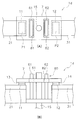
以上、第1~第3実施形態に係るリレー1a-1cについて説明したが、可動接触片7の形状、或いは配置は、上記の実施形態のものに限らず変更されてもよい。例えば、図9Aは、第4実施形態に係るリレー1dの接点ケース18内の構成を示す平面図である。図9Bは、第4実施形態に係るリレー1dの接点ケース18内の構成を示す側面図である。
図9A及び図9Bに示すように、可動接触片7は、第1孔81と第2孔82とを含む。第1孔81と第2孔82とは、上下方向に可動接触片7を貫通している。第1孔81は、上下方向において第1壁部61に対向して配置される。第2孔82は、上下方向において第2壁部62に対向して配置される。詳細には、第1孔81は、第1壁部61の上方に配置される。第2孔82は、第2壁部62の上方に配置される。第1孔81は、第1壁部61が挿入可能な大きさを有する。第2孔82は、第2壁部62が挿入可能な大きさを有する。
第4実施形態に係るリレー1dでは、少なくとも閉状態で、第1壁部61が第1孔81内に配置され、第2壁部62が第2孔82内に配置される。それにより、第1壁部61及び第2壁部62と可動接触片7と干渉を回避することができる。なお、閉状態のみならず開状態でも、第1壁部61が第1孔81内に配置され、第2壁部62が第2孔82内に配置されてもよい。
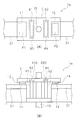
図10Aは、第5実施形態に係るリレー1eの接点ケース18内の構成を示す平面図である。図10Bは、第5実施形態に係るリレー1eの接点ケース18内の構成を示す側面図である。
図10A及び図10Bに示すように、可動接触片7は、第1凹部83と第2凹部84とを含む。第1凹部83と第2凹部84とは、可動接触片7の底面から上方に凹んだ形状を有する。第1凹部83は、上下方向において第1壁部61に対向して配置される。第2凹部84は、上下方向において第2壁部62に対向して配置される。詳細には、第1凹部83は、第1壁部61の上方に配置される。第2凹部84は、第2壁部62の上方に配置される。第1凹部83は、第1壁部61の上端610が挿入可能な大きさを有する。第2凹部84は、第2壁部62の上端620が挿入可能な大きさを有する。
第4実施形態に係るリレー1dでは、少なくとも閉状態で、第1壁部61が第1凹部83内に配置され、第2壁部62が第2凹部84内に配置される。それにより、第1壁部61及び第2壁部62と可動接触片7と干渉を回避することができる。なお、閉状態のみならず開状態でも、第1壁部61が第1凹部83内に配置され、第2壁部62が第2凹部84内に配置されてもよい。
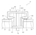
図11は、第6実施形態に係るリレー1fの接点ケース18内の構成を示す側面図である。図11に示すように、可動接触片7は、第1接点支持部91と、第2接点支持部92と、中間部93と、第1屈曲部94と、第2屈曲部95とを含む。第1接点支持部91は、第1可動接点13を支持している。第2接点支持部92は、第2可動接点14を支持している。第1屈曲部94は、第1接点支持部91から上方に向かって屈曲した形状を有する。第1屈曲部94は、左右方向において第1接点支持部91の外側に位置する。第2屈曲部95は、第2接点支持部92から上方に向かって屈曲した形状を有する。第2屈曲部95は、左右方向において第2接点支持部92の外側に位置する。中間部93は、第1屈曲部94と第2屈曲部95との間に位置している。中間部93は、第1接点支持部91及び第2接点支持部92よりも上方に位置する。
第6実施形態に係るリレー1fでは、第1接点支持部91の内端部910と第2接点支持部92の内端部920とが互いに離れて配置される。第1壁部61及び第2壁部62は、第1接点支持部91の内端部910と第2接点支持部92の内端部920との間の空間に対向して配置される。少なくとも閉状態で、第1接点支持部91の内端部910と第2接点支持部92の内端部920との間に、第1壁部61と第2壁部62とが配置される。それにより、第1壁部61及び第2壁部62と可動接触片7と干渉を回避することができる。なお、閉状態のみならず開状態でも、第1接点支持部91の内端部910と第2接点支持部92の内端部920との間に、第1壁部61と第2壁部62とが配置されてもよい。
上記の実施形態では、駆動装置4が駆動軸15をコイル41側から引き込むことで、可動接触片7が接触方向Z1に移動する。また、駆動装置4が駆動軸15をコイル41側から押し出すことで、可動接触片7が開離方向Z2に移動する。しかし、接点を開閉するための駆動軸15の動作方向は、上記の実施形態と逆であってもよい。すなわち、駆動装置4が駆動軸15をコイル41側に引き込むことで、可動接触片7が開離方向Z2に移動してもよい。駆動装置4が駆動軸15をコイル41側から押し出すことで、可動接触片7が接触方向Z1に移動してもよい。すなわち、接触方向Z1と開離方向Z2とは、上記の実施形態とは上下に逆であってもよい。
例えば、図12は、第7実施形態に係るリレー1gの接点ケース18内の構成を示す側面図である。図12に示すように、第7実施形態に係るリレー1gでは、可動接触片7は、第1固定接点11及び第2固定接点12の下方に配置される。可動接触片7が上方すなわち接触方向Z1に移動することで、第1可動接点13及び第2可動接点14が第1固定接点11及び第2固定接点12と接触する。可動接触片7が下方すなわち開離方向Z2に移動することで、第1可動接点13及び第2可動接点14が第1固定接点11及び第2固定接点12から開離する。
第7実施形態に係るリレー1gにおいても、第1実施形態に係るリレー1aと同様に、第1壁部61及び第2壁部62が配置されている。第7実施形態に係るリレー1gでは、第1壁部61の下端611と第2壁部62の下端621とが、可動接触片7と対向している。また、可動接触片7は、第1壁部61及び第2壁部62との干渉を避けるように湾曲した形状を有している。なお、可動接触片7は、第4~第6実施形態に係るリレー1d-1fの可動接触片7と同様の形状であってもよい。
以上、本発明の実施形態について説明したが、本発明は上記実施形態に限定されるものではなく、発明の要旨を逸脱しない範囲で種々の変更が可能である。例えば、駆動装置4の構成が変更されてもよい。コイル41、スプール42、鉄心43、復帰バネ44、或いはヨーク45の形状、或いは配置が変更されてもよい。ケース2の形状、或いは配置が変更されてもよい。
第1固定端子5、第2固定端子6、可動接触片7の形状、或いは配置が変更されてもよい。例えば、第1外部接続部24及び第2外部接続部34は、ケース2から上方に突出してもよい。或いは、第1外部接続部24及び第2外部接続部34は、ケース2から前後方向に突出してもよい。
第1固定接点11は、第1固定端子5と別体であってもよく、或いは一体であってもよい。第2固定接点12は、第2固定端子6と別体であってもよく、或いは一体であってもよい。第1可動接点13は、可動接触片7と別体であってもよく、或いは一体であってもよい。第2可動接点14は、可動接触片7と別体であってもよく、或いは一体であってもよい。
壁部60の形状、或いは配置が変更されてもよい。例えは、第1~第4壁部61-64の形状、或いは配置が変更されてもよい。第3壁部63及び第4壁部64が省略されてもよい。
本発明によれば、リレーにおいて可動接触片の動作を阻害することを回避しながら、アークの遮断性能を向上させることができる。
4 駆動装置
7 可動接触片
8 接触片保持部
11 第1固定接点
12 第2固定接点
13 第1可動接点
14 第2可動接点
60 壁部
71 第1接点支持部
73 第1中間部
74 第1曲げ部
81 第1孔
7 可動接触片
8 接触片保持部
11 第1固定接点
12 第2固定接点
13 第1可動接点
14 第2可動接点
60 壁部
71 第1接点支持部
73 第1中間部
74 第1曲げ部
81 第1孔
Claims (10)
- 長手方向に互いに離れて配置された第1可動接点と第2可動接点とを含む可動接触片と
前記第1可動接点に対向して配置された第1固定接点を含む第1固定端子と、
前記第2可動接点に対向して配置された第2固定接点を含む第2固定端子と、
前記第1可動接点及び前記第2可動接点が前記第1固定接点及び前記第2固定接点に対して接触する方向及び開離する方向に前記可動接触片を移動させる駆動装置と、
前記長手方向において前記第1固定接点及び前記第2固定接点の内側に配置された壁部と、
を備え、
前記壁部の少なくとも一部は、前記可動接触片の移動方向において前記第1固定接点及び前記第2固定接点を前記可動接触片側に越えた位置に配置されており、
前記可動接触片は、前記第1可動接点及び前記第2可動接点が前記第1固定接点及び前記第2固定接点に接触している状態で前記壁部を避けた形状を有する、
リレー。 - 前記壁部は、アークの熱により消弧ガスを発生させる消弧材で形成されている、
請求項1に記載のリレー。 - 前記可動接触片は、前記壁部から離れる方向に凹んだ形状を有する、
請求項1又は2に記載のリレー。 - 前記可動接触片は、前記壁部から離れる方向に湾曲した曲げ部を含む、
請求項1から3のいずれかに記載のリレー。 - 前記曲げ部は、前記壁部に対向して配置される、
請求項4に記載のリレー。 - 前記可動接触片は、前記壁部に対向して配置された孔を含む、
請求項1に記載のリレー。 - 前記可動接触片は、前記壁部に対向して配置された凹部を含む、
請求項1に記載のリレー。 - 前記可動接触片は、
前記第1可動接点を支持する第1接点支持部と、
前記第2可動接点を支持する第2接点支持部と、
を含み、
前記可動接触片の長手方向において、前記第1接点支持部の内端部と前記第2接点支持部の内端部とは互いに離れて配置され、
前記壁部は、前記第1接点支持部の内端部と前記第2接点支持部の内端部との間の空間に対向して配置される、
請求項1に記載のリレー。 - 前記第1可動接点及び前記第2可動接点が前記第1固定接点及び前記第2固定接点に接触している状態で、前記可動接触片の長手方向から見て、前記壁部は前記第1可動接点及び前記第1固定接点と重なる、
請求項1から8のいずれかに記載のリレー。 - 前記第1固定端子は、
前記第1固定接点を支持しており、前記長手方向において前記第1固定接点から外側へ延びる接点支持部と、
前記接点支持部から前記可動接触片の移動方向と平行な方向に延びる中間部と、
を含む、
請求項1から9のいずれかに記載のリレー。
Priority Applications (3)
| Application Number | Priority Date | Filing Date | Title |
|---|---|---|---|
| CN201980049847.XA CN112514024B (zh) | 2018-08-21 | 2019-02-19 | 继电器 |
| DE112019004176.2T DE112019004176T5 (de) | 2018-08-21 | 2019-02-19 | Relais |
| US17/262,214 US11621136B2 (en) | 2018-08-21 | 2019-02-19 | Relay |
Applications Claiming Priority (2)
| Application Number | Priority Date | Filing Date | Title |
|---|---|---|---|
| JP2018-154579 | 2018-08-21 | ||
| JP2018154579A JP7115137B2 (ja) | 2018-08-21 | 2018-08-21 | リレー |
Publications (1)
| Publication Number | Publication Date |
|---|---|
| WO2020039619A1 true WO2020039619A1 (ja) | 2020-02-27 |
Family
ID=69592996
Family Applications (1)
| Application Number | Title | Priority Date | Filing Date |
|---|---|---|---|
| PCT/JP2019/006169 Ceased WO2020039619A1 (ja) | 2018-08-21 | 2019-02-19 | リレー |
Country Status (5)
| Country | Link |
|---|---|
| US (1) | US11621136B2 (ja) |
| JP (1) | JP7115137B2 (ja) |
| CN (1) | CN112514024B (ja) |
| DE (1) | DE112019004176T5 (ja) |
| WO (1) | WO2020039619A1 (ja) |
Families Citing this family (5)
| Publication number | Priority date | Publication date | Assignee | Title |
|---|---|---|---|---|
| JP7423944B2 (ja) * | 2019-09-13 | 2024-01-30 | オムロン株式会社 | 電磁継電器 |
| JP2021134115A (ja) | 2020-02-26 | 2021-09-13 | 住友化学株式会社 | 焼結体の製造方法 |
| JP7067580B2 (ja) * | 2020-03-18 | 2022-05-16 | 株式会社デンソーエレクトロニクス | 電磁継電器、および、電磁継電器の製造方法 |
| JP7444041B2 (ja) * | 2020-12-15 | 2024-03-06 | オムロン株式会社 | 接点装置及び電源コンセント |
| JP7392678B2 (ja) * | 2021-03-05 | 2023-12-06 | オムロン株式会社 | 電磁継電器 |
Citations (3)
| Publication number | Priority date | Publication date | Assignee | Title |
|---|---|---|---|---|
| JP2008282719A (ja) * | 2007-05-11 | 2008-11-20 | Nec Tokin Corp | 電気接点開閉部 |
| WO2012060090A1 (ja) * | 2010-11-01 | 2012-05-10 | 日本特殊陶業株式会社 | 継電器 |
| WO2013051263A1 (ja) * | 2011-10-07 | 2013-04-11 | 富士電機株式会社 | 接点装置及びこれを使用した電磁接触器 |
Family Cites Families (24)
| Publication number | Priority date | Publication date | Assignee | Title |
|---|---|---|---|---|
| US2571735A (en) * | 1947-01-02 | 1951-10-16 | S & C Electric Co | Fuse construction |
| US5892194A (en) * | 1996-03-26 | 1999-04-06 | Matsushita Electric Works, Ltd. | Sealed contact device with contact gap adjustment capability |
| US7551049B2 (en) * | 2004-11-08 | 2009-06-23 | Denso Corporation | Structure of electromagnetic switch for starter |
| DE602006002209D1 (de) * | 2005-03-28 | 2008-09-25 | Matsushita Electric Works Ltd | Kontaktvorrichtung |
| JP4544172B2 (ja) | 2006-02-10 | 2010-09-15 | 株式会社デンソー | 電磁継電器 |
| JP5163317B2 (ja) * | 2008-06-30 | 2013-03-13 | オムロン株式会社 | 接点装置 |
| KR101137015B1 (ko) * | 2010-10-15 | 2012-04-19 | 엘에스산전 주식회사 | 전자개폐장치 |
| KR101072627B1 (ko) * | 2010-10-15 | 2011-10-13 | 엘에스산전 주식회사 | 전자 개폐기의 가동접점 조립체 |
| JP2012104362A (ja) * | 2010-11-10 | 2012-05-31 | Panasonic Corp | 接点装置 |
| JP5809443B2 (ja) * | 2011-05-19 | 2015-11-10 | 富士電機株式会社 | 接点機構及びこれを使用した電磁接触器 |
| JP5684650B2 (ja) * | 2011-05-19 | 2015-03-18 | 富士電機株式会社 | 電磁接触器 |
| JP5986419B2 (ja) * | 2012-04-13 | 2016-09-06 | 富士電機株式会社 | 接点装置及びこれを使用した電磁開閉器 |
| JP5990028B2 (ja) * | 2012-04-13 | 2016-09-07 | 富士電機機器制御株式会社 | 接点装置及びこれを使用した電磁開閉器 |
| JP6062734B2 (ja) * | 2012-12-20 | 2017-01-18 | 日本特殊陶業株式会社 | 継電器 |
| JP6300157B2 (ja) * | 2013-08-02 | 2018-03-28 | パナソニックIpマネジメント株式会社 | 電磁継電器 |
| JP6202943B2 (ja) * | 2013-08-26 | 2017-09-27 | 富士通コンポーネント株式会社 | 電磁継電器 |
| JP6447919B2 (ja) * | 2015-04-07 | 2019-01-09 | パナソニックIpマネジメント株式会社 | 電磁継電器 |
| JP6590273B2 (ja) * | 2015-04-13 | 2019-10-16 | パナソニックIpマネジメント株式会社 | 接点装置および電磁継電器 |
| DE102015218768B3 (de) * | 2015-09-29 | 2017-03-02 | Continental Automotive Gmbh | Elektromagnetischer Aktor, elektromagnetisches Ventil und Kraftstoffhochdruckpumpe |
| JP6601213B2 (ja) * | 2015-12-24 | 2019-11-06 | 富士電機機器制御株式会社 | 接点装置、電磁接触器及び接点装置のアーク消弧用ガス封入方法 |
| JP6690459B2 (ja) * | 2016-08-10 | 2020-04-28 | オムロン株式会社 | 電磁継電器 |
| JP6836241B2 (ja) * | 2016-12-27 | 2021-02-24 | 富士通コンポーネント株式会社 | 電磁継電器 |
| JP6848923B2 (ja) * | 2018-03-30 | 2021-03-24 | オムロン株式会社 | リレー |
| JP6835029B2 (ja) * | 2018-03-30 | 2021-02-24 | オムロン株式会社 | リレー |
-
2018
- 2018-08-21 JP JP2018154579A patent/JP7115137B2/ja active Active
-
2019
- 2019-02-19 WO PCT/JP2019/006169 patent/WO2020039619A1/ja not_active Ceased
- 2019-02-19 CN CN201980049847.XA patent/CN112514024B/zh active Active
- 2019-02-19 DE DE112019004176.2T patent/DE112019004176T5/de active Pending
- 2019-02-19 US US17/262,214 patent/US11621136B2/en active Active
Patent Citations (3)
| Publication number | Priority date | Publication date | Assignee | Title |
|---|---|---|---|---|
| JP2008282719A (ja) * | 2007-05-11 | 2008-11-20 | Nec Tokin Corp | 電気接点開閉部 |
| WO2012060090A1 (ja) * | 2010-11-01 | 2012-05-10 | 日本特殊陶業株式会社 | 継電器 |
| WO2013051263A1 (ja) * | 2011-10-07 | 2013-04-11 | 富士電機株式会社 | 接点装置及びこれを使用した電磁接触器 |
Also Published As
| Publication number | Publication date |
|---|---|
| US20210304994A1 (en) | 2021-09-30 |
| US11621136B2 (en) | 2023-04-04 |
| CN112514024A (zh) | 2021-03-16 |
| DE112019004176T5 (de) | 2021-05-20 |
| JP7115137B2 (ja) | 2022-08-09 |
| JP2020030911A (ja) | 2020-02-27 |
| CN112514024B (zh) | 2025-01-17 |
Similar Documents
| Publication | Publication Date | Title |
|---|---|---|
| CN112543987B (zh) | 继电器 | |
| JP5809443B2 (ja) | 接点機構及びこれを使用した電磁接触器 | |
| CN103238198B (zh) | 电磁接触器 | |
| JP5986419B2 (ja) | 接点装置及びこれを使用した電磁開閉器 | |
| JP2020030911A (ja) | リレー | |
| JP5856426B2 (ja) | 接点装置及びこれを使用した電磁接触器 | |
| JP6359896B2 (ja) | 接点機構及びこれを使用した電磁接触器 | |
| JP7047662B2 (ja) | リレー | |
| JP5990090B2 (ja) | 電磁開閉器 | |
| CN103534779B (zh) | 电磁接触器 | |
| JP6996412B2 (ja) | 電磁継電器 | |
| JP7390560B2 (ja) | 電磁継電器及び電磁継電器用絶縁部材 | |
| JP7135567B2 (ja) | リレー | |
| WO2012157218A1 (ja) | 電磁接触器 | |
| WO2015136731A1 (ja) | 封止接点装置 | |
| JP6291871B2 (ja) | 接点装置及びこれを使用した電磁接触器 | |
| JP2013246873A (ja) | 接点装置 | |
| WO2020137107A1 (ja) | 電磁継電器 | |
| JP7255440B2 (ja) | 接点機構及びこれを使用した電磁接触器 | |
| WO2022185746A1 (ja) | 電磁継電器 |
Legal Events
| Date | Code | Title | Description |
|---|---|---|---|
| 121 | Ep: the epo has been informed by wipo that ep was designated in this application |
Ref document number: 19851318 Country of ref document: EP Kind code of ref document: A1 |
|
| 122 | Ep: pct application non-entry in european phase |
Ref document number: 19851318 Country of ref document: EP Kind code of ref document: A1 |
|
| WWG | Wipo information: grant in national office |
Ref document number: 201980049847.X Country of ref document: CN |