WO2020036085A1 - 屈曲構造体及びこれを用いた関節機能部 - Google Patents
屈曲構造体及びこれを用いた関節機能部 Download PDFInfo
- Publication number
- WO2020036085A1 WO2020036085A1 PCT/JP2019/030599 JP2019030599W WO2020036085A1 WO 2020036085 A1 WO2020036085 A1 WO 2020036085A1 JP 2019030599 W JP2019030599 W JP 2019030599W WO 2020036085 A1 WO2020036085 A1 WO 2020036085A1
- Authority
- WO
- WIPO (PCT)
- Prior art keywords
- coil portion
- outer coil
- axial direction
- bent
- bending
- Prior art date
Links
- 238000005452 bending Methods 0.000 title claims abstract description 79
- 230000008407 joint function Effects 0.000 title claims abstract description 39
- 238000004804 winding Methods 0.000 claims description 79
- 230000006835 compression Effects 0.000 claims description 10
- 238000007906 compression Methods 0.000 claims description 10
- 238000006073 displacement reaction Methods 0.000 claims description 10
- 230000001105 regulatory effect Effects 0.000 claims description 7
- 230000000052 comparative effect Effects 0.000 description 6
- 230000000694 effects Effects 0.000 description 6
- 230000037431 insertion Effects 0.000 description 6
- 238000003780 insertion Methods 0.000 description 6
- 239000002184 metal Substances 0.000 description 4
- 239000011347 resin Substances 0.000 description 4
- 229920005989 resin Polymers 0.000 description 4
- 230000000087 stabilizing effect Effects 0.000 description 4
- 230000007423 decrease Effects 0.000 description 3
- 239000000463 material Substances 0.000 description 3
- 239000012636 effector Substances 0.000 description 2
- 230000004323 axial length Effects 0.000 description 1
- 230000006870 function Effects 0.000 description 1
- 230000000149 penetrating effect Effects 0.000 description 1
- 230000002093 peripheral effect Effects 0.000 description 1
Images


Classifications
-
- A—HUMAN NECESSITIES
- A61—MEDICAL OR VETERINARY SCIENCE; HYGIENE
- A61B—DIAGNOSIS; SURGERY; IDENTIFICATION
- A61B17/00—Surgical instruments, devices or methods, e.g. tourniquets
- A61B17/28—Surgical forceps
- A61B17/29—Forceps for use in minimally invasive surgery
- A61B17/2909—Handles
-
- A—HUMAN NECESSITIES
- A61—MEDICAL OR VETERINARY SCIENCE; HYGIENE
- A61B—DIAGNOSIS; SURGERY; IDENTIFICATION
- A61B17/00—Surgical instruments, devices or methods, e.g. tourniquets
- A61B17/28—Surgical forceps
- A61B17/29—Forceps for use in minimally invasive surgery
-
- A—HUMAN NECESSITIES
- A61—MEDICAL OR VETERINARY SCIENCE; HYGIENE
- A61B—DIAGNOSIS; SURGERY; IDENTIFICATION
- A61B34/00—Computer-aided surgery; Manipulators or robots specially adapted for use in surgery
- A61B34/30—Surgical robots
-
- A—HUMAN NECESSITIES
- A61—MEDICAL OR VETERINARY SCIENCE; HYGIENE
- A61B—DIAGNOSIS; SURGERY; IDENTIFICATION
- A61B34/00—Computer-aided surgery; Manipulators or robots specially adapted for use in surgery
- A61B34/30—Surgical robots
- A61B34/37—Master-slave robots
-
- A—HUMAN NECESSITIES
- A61—MEDICAL OR VETERINARY SCIENCE; HYGIENE
- A61B—DIAGNOSIS; SURGERY; IDENTIFICATION
- A61B34/00—Computer-aided surgery; Manipulators or robots specially adapted for use in surgery
- A61B34/70—Manipulators specially adapted for use in surgery
- A61B34/71—Manipulators operated by drive cable mechanisms
-
- B—PERFORMING OPERATIONS; TRANSPORTING
- B25—HAND TOOLS; PORTABLE POWER-DRIVEN TOOLS; MANIPULATORS
- B25J—MANIPULATORS; CHAMBERS PROVIDED WITH MANIPULATION DEVICES
- B25J17/00—Joints
-
- B—PERFORMING OPERATIONS; TRANSPORTING
- B25—HAND TOOLS; PORTABLE POWER-DRIVEN TOOLS; MANIPULATORS
- B25J—MANIPULATORS; CHAMBERS PROVIDED WITH MANIPULATION DEVICES
- B25J17/00—Joints
- B25J17/02—Wrist joints
-
- B—PERFORMING OPERATIONS; TRANSPORTING
- B25—HAND TOOLS; PORTABLE POWER-DRIVEN TOOLS; MANIPULATORS
- B25J—MANIPULATORS; CHAMBERS PROVIDED WITH MANIPULATION DEVICES
- B25J3/00—Manipulators of master-slave type, i.e. both controlling unit and controlled unit perform corresponding spatial movements
-
- B—PERFORMING OPERATIONS; TRANSPORTING
- B25—HAND TOOLS; PORTABLE POWER-DRIVEN TOOLS; MANIPULATORS
- B25J—MANIPULATORS; CHAMBERS PROVIDED WITH MANIPULATION DEVICES
- B25J9/00—Programme-controlled manipulators
- B25J9/10—Programme-controlled manipulators characterised by positioning means for manipulator elements
- B25J9/1075—Programme-controlled manipulators characterised by positioning means for manipulator elements with muscles or tendons
-
- F—MECHANICAL ENGINEERING; LIGHTING; HEATING; WEAPONS; BLASTING
- F16—ENGINEERING ELEMENTS AND UNITS; GENERAL MEASURES FOR PRODUCING AND MAINTAINING EFFECTIVE FUNCTIONING OF MACHINES OR INSTALLATIONS; THERMAL INSULATION IN GENERAL
- F16F—SPRINGS; SHOCK-ABSORBERS; MEANS FOR DAMPING VIBRATION
- F16F3/00—Spring units consisting of several springs, e.g. for obtaining a desired spring characteristic
- F16F3/02—Spring units consisting of several springs, e.g. for obtaining a desired spring characteristic with springs made of steel or of other material having low internal friction
- F16F3/04—Spring units consisting of several springs, e.g. for obtaining a desired spring characteristic with springs made of steel or of other material having low internal friction composed only of wound springs
- F16F3/06—Spring units consisting of several springs, e.g. for obtaining a desired spring characteristic with springs made of steel or of other material having low internal friction composed only of wound springs of which some are placed around others in such a way that they damp each other by mutual friction
-
- A—HUMAN NECESSITIES
- A61—MEDICAL OR VETERINARY SCIENCE; HYGIENE
- A61B—DIAGNOSIS; SURGERY; IDENTIFICATION
- A61B17/00—Surgical instruments, devices or methods, e.g. tourniquets
- A61B17/28—Surgical forceps
-
- A—HUMAN NECESSITIES
- A61—MEDICAL OR VETERINARY SCIENCE; HYGIENE
- A61B—DIAGNOSIS; SURGERY; IDENTIFICATION
- A61B17/00—Surgical instruments, devices or methods, e.g. tourniquets
- A61B17/00234—Surgical instruments, devices or methods, e.g. tourniquets for minimally invasive surgery
- A61B2017/00292—Surgical instruments, devices or methods, e.g. tourniquets for minimally invasive surgery mounted on or guided by flexible, e.g. catheter-like, means
- A61B2017/003—Steerable
- A61B2017/00305—Constructional details of the flexible means
-
- A—HUMAN NECESSITIES
- A61—MEDICAL OR VETERINARY SCIENCE; HYGIENE
- A61B—DIAGNOSIS; SURGERY; IDENTIFICATION
- A61B17/00—Surgical instruments, devices or methods, e.g. tourniquets
- A61B17/00234—Surgical instruments, devices or methods, e.g. tourniquets for minimally invasive surgery
- A61B2017/00292—Surgical instruments, devices or methods, e.g. tourniquets for minimally invasive surgery mounted on or guided by flexible, e.g. catheter-like, means
- A61B2017/003—Steerable
- A61B2017/00318—Steering mechanisms
- A61B2017/00323—Cables or rods
-
- A—HUMAN NECESSITIES
- A61—MEDICAL OR VETERINARY SCIENCE; HYGIENE
- A61B—DIAGNOSIS; SURGERY; IDENTIFICATION
- A61B17/00—Surgical instruments, devices or methods, e.g. tourniquets
- A61B17/28—Surgical forceps
- A61B17/29—Forceps for use in minimally invasive surgery
- A61B2017/2901—Details of shaft
- A61B2017/2905—Details of shaft flexible
-
- A—HUMAN NECESSITIES
- A61—MEDICAL OR VETERINARY SCIENCE; HYGIENE
- A61B—DIAGNOSIS; SURGERY; IDENTIFICATION
- A61B17/00—Surgical instruments, devices or methods, e.g. tourniquets
- A61B17/28—Surgical forceps
- A61B17/29—Forceps for use in minimally invasive surgery
- A61B2017/2901—Details of shaft
- A61B2017/2908—Multiple segments connected by articulations
-
- A—HUMAN NECESSITIES
- A61—MEDICAL OR VETERINARY SCIENCE; HYGIENE
- A61B—DIAGNOSIS; SURGERY; IDENTIFICATION
- A61B17/00—Surgical instruments, devices or methods, e.g. tourniquets
- A61B17/28—Surgical forceps
- A61B17/29—Forceps for use in minimally invasive surgery
- A61B17/2909—Handles
- A61B2017/2912—Handles transmission of forces to actuating rod or piston
- A61B2017/2918—Handles transmission of forces to actuating rod or piston flexible handles
-
- A—HUMAN NECESSITIES
- A61—MEDICAL OR VETERINARY SCIENCE; HYGIENE
- A61B—DIAGNOSIS; SURGERY; IDENTIFICATION
- A61B17/00—Surgical instruments, devices or methods, e.g. tourniquets
- A61B17/28—Surgical forceps
- A61B17/29—Forceps for use in minimally invasive surgery
- A61B17/2909—Handles
- A61B2017/2912—Handles transmission of forces to actuating rod or piston
- A61B2017/2919—Handles transmission of forces to actuating rod or piston details of linkages or pivot points
- A61B2017/292—Handles transmission of forces to actuating rod or piston details of linkages or pivot points connection of actuating rod to handle, e.g. ball end in recess
-
- A—HUMAN NECESSITIES
- A61—MEDICAL OR VETERINARY SCIENCE; HYGIENE
- A61B—DIAGNOSIS; SURGERY; IDENTIFICATION
- A61B17/00—Surgical instruments, devices or methods, e.g. tourniquets
- A61B17/28—Surgical forceps
- A61B17/29—Forceps for use in minimally invasive surgery
- A61B2017/2926—Details of heads or jaws
- A61B2017/2932—Transmission of forces to jaw members
- A61B2017/2939—Details of linkages or pivot points
-
- A—HUMAN NECESSITIES
- A61—MEDICAL OR VETERINARY SCIENCE; HYGIENE
- A61B—DIAGNOSIS; SURGERY; IDENTIFICATION
- A61B34/00—Computer-aided surgery; Manipulators or robots specially adapted for use in surgery
- A61B34/30—Surgical robots
- A61B2034/301—Surgical robots for introducing or steering flexible instruments inserted into the body, e.g. catheters or endoscopes
-
- A—HUMAN NECESSITIES
- A61—MEDICAL OR VETERINARY SCIENCE; HYGIENE
- A61B—DIAGNOSIS; SURGERY; IDENTIFICATION
- A61B34/00—Computer-aided surgery; Manipulators or robots specially adapted for use in surgery
- A61B34/30—Surgical robots
- A61B2034/305—Details of wrist mechanisms at distal ends of robotic arms
- A61B2034/306—Wrists with multiple vertebrae
-
- A—HUMAN NECESSITIES
- A61—MEDICAL OR VETERINARY SCIENCE; HYGIENE
- A61B—DIAGNOSIS; SURGERY; IDENTIFICATION
- A61B34/00—Computer-aided surgery; Manipulators or robots specially adapted for use in surgery
- A61B34/70—Manipulators specially adapted for use in surgery
Definitions
- the present invention relates to a bending structure provided for a joint function unit such as a robot and a joint function unit using the same.
- the flexible member disclosed in Patent Document 1 is configured by mutually engaging a plurality of disk elements so as to be swingable, and performs a bending operation as a whole by swinging each disk element.
- the flexible member having such a configuration can smoothly perform the bending operation, secure rigidity against compression in the axial direction, and stabilize the bending operation.
- Patent Document 1 has a problem that the structure is complicated because a plurality of disk elements are engaged with each other.
- the problem to be solved is that the structure becomes complicated when the bending operation is stabilized.
- the present invention is a bending structure that is bendable in the axial direction in order to simplify the structure while stabilizing the bending operation, and is wound in a coil shape to form a plurality of winding portions in the axial direction.
- An outer coil portion made of a wire having a plurality of winding portions wound in a coil shape and having a plurality of winding portions in the axial direction, and an inner coil portion located in the outer coil portion.
- the main feature of the bent structure is to fit between the winding portions while contacting the portions.
- the present invention is a joint function unit to which the bent structure is applied, the base including a base and a movable part displaced with respect to the base, wherein the bent structure is provided between the base and the movable part.
- the most main feature of the joint function section is to bend in accordance with the displacement of the movable section with respect to the base section.
- the bent structure is configured by positioning the inner coil portion in the outer coil portion, the structure can be simplified.
- the winding portion of the inner coil portion is fitted to the adjacent winding portion of the outer coil portion while being in contact with the adjacent winding portion, rigidity in the axial direction can be secured.
- the inner coil portion is displaced outside the bend while reducing the gap between the outer coil portions inside the bend, and the gap between the outer coil portions is increased outside the bend to allow displacement of the inner coil portion.
- the gap between the outer coil portions becomes smaller inside the bend and the gap between the outer coil portions becomes larger outside the bend, so that the length of the outer coil portion at the axial center is shorter than when the straight portion is straight.
- FIG. 2 is an enlarged view showing a part of the bent structure of FIG. 1 (Example 1). It is sectional drawing which shows the bending state of the bending structure of FIG. 1 (Example 1).
- FIG. 4 is an enlarged view showing a part of the bent structure of FIG. 3 (Example 1). It is a schematic sectional drawing which shows the fall of the inner coil part from the outer coil part, (A) is the state before falling off, (B) is the state after falling off (Example 1).
- FIG. 14 is a perspective view showing a part of a robot forceps (Example 6).
- FIG. 12 is a sectional view of the robot forceps of FIG. 11 (Example 6).
- FIG. 12 is a perspective view illustrating a bent portion of the robot forceps of FIG. 11 (Example 6). It is sectional drawing of the bending part of FIG. 13 (Example 6).
- the bending structure is a bending structure that can be bent in the axial direction, and is wound in a coil shape and is wound in a coil shape with an outer coil portion made of a wire having a plurality of winding portions in the axial direction. And an inner coil portion which is made of a wire having a plurality of winding portions in the axial direction and is located inside the outer coil portion.
- the outer coil portion has a plurality of gaps separating the winding portions adjacent in the axial direction
- the inner coil portion has the winding portions provided corresponding to the gaps of the outer coil portion, and is adjacent to the outer coil portion. It fits between the windings while contacting the windings.
- the outer coil portion may have a gap between each of the winding portions that are adjacent in the axial direction, but may have a configuration that has a gap only in a part of the axial direction.
- the movable length in which the inner coil portion can move radially with respect to the axis of the outer coil portion may be equal to or less than half of (diameter of outer coil portion ⁇ diameter of inner coil portion).
- a configuration may be adopted in which a regulating member that regulates the movement of the inner coil portion is provided so that the movable length is equal to or less than half of (diameter of outer coil portion ⁇ diameter of inner coil portion).
- the restricting member may be a flexible member, and the bent structure may be configured to be able to bend together with the flexible member by inserting the flexible member movably in the axial direction.
- the inner coil part and the outer coil part can be configured separately or integrally. When the inner coil portion and the outer coil portion are formed separately, the inner coil portion may be screwed into the outer coil portion.
- the joint function unit to which the bending structure of the flexible member is applied may have a configuration including a base and a movable unit displaced with respect to the base.
- the bending structure is provided between the base and the movable part, and bends according to the displacement of the movable part with respect to the base.
- the joint function unit may include a flexible tube that can be extended and contracted in the axial direction and is provided between the base unit and the movable unit.
- the bent structure is disposed in the axial direction along the axis of the flexible tube.
- FIG. 1 is a sectional view showing a bent structure of a flexible member according to a first embodiment of the present invention
- FIG. 2 is an enlarged view showing the same part.
- the bending structure 1 is applied to a joint function unit such as a robot, a manipulator, or an actuator in various fields.
- the bent structure 1 is provided between the base and the movable part of the joint function part, and supports the movable part displaceably with respect to the base by bending.
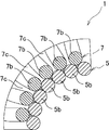
- the bent structure 1 according to the present embodiment has a double coil shape and includes an outer coil portion 5 and an inner coil portion 7. With this double coil shape, the bent structure 1 of the present embodiment can be bent in the axial direction, and when bent by an external force, the inner diameter side of the bend contracts and the outer diameter side of the bend expands.
- the axial length of the central axis or the axis O is substantially constant before and after bending and during bending, and is configured to restrict axial compression during non-bending and the like.
- the bent structure 1 of this embodiment also includes a flexible member 3 as a regulating member.
- the flexible member 3 penetrates the bent structure 1 so as to be movable in the axial direction, and regulates the radial displacement of the inner and outer coil portions 5 and 7 as will be described in detail later.
- the flexible member 3 of this embodiment is configured using, for example, a push-pull cable or the like. Accordingly, the bending structure 1 also has a function of guiding the flexible member 3 in the axial direction, and can bend together with the flexible member 3 in accordance with the bending operation of the joint function unit.
- bending means that the axis O of the joint function part or the bending structure 1 is bent or bent. Further, the flexible member 3 can be omitted.
- the outer coil portion 5 is a coil spring, and is made of a wire 5a wound in a coil shape. Therefore, the outer coil part 5 has a plurality of winding parts 5b in the axial direction. In addition, the winding part 5b means one turn which comprises a coil shape (the same below).
- the material of the wire 5a can be metal, resin, or the like.
- the cross section of the wire 5a is formed in a circular shape, but may be an ellipse or the like.
- the center diameter D1 of the outer coil portion 5 is constant from one axial end to the other end. However, the center diameter D1 of the outer coil portion 5 can be changed in the axial direction.
- the outer coil portion 5 has a plurality of gaps 5c in which the winding portions 5b adjacent in the axial direction are separated in the axial direction.
- the gaps 5c of this embodiment are formed between the winding portions 5b adjacent in the axial direction, and all the gaps 5c have the same axial dimension.
- the gap 5c may be provided only between some of the winding portions 5b in the axial direction. It is also possible to change the dimension of the gap 5c in the axial direction.
- the inner coil portion 7 is a coil spring, and is formed of a wire 7a wound in a coil shape having a plurality of winding portions 7b in the axial direction.
- the inner coil part 7 can be made of metal or resin as the material of the wire 7a, and the wire 7a has a circular cross section, but can have an ellipse or the like.
- the inner coil portion 7 is located inside the outer coil portion 5, and an insertion portion 9 for inserting the flexible member 3 is defined on the inner periphery.
- the inner coil part 7 of this embodiment is screwed into the outer coil part 5. By this screwing, the winding portion 7b of the inner coil portion 7 is positioned between the adjacent winding portions 5b of the outer coil portion 5. Therefore, the inner coil portion 7 has a configuration in which the winding portion 7b is provided corresponding to the gap 5c of the outer coil portion 5.
- the winding portion 7b of the inner coil portion 7 fits between the winding portions 5b while being in contact with the adjacent winding portion 5b of the outer coil portion 5 by setting the center diameter D2 and the wire diameter d2 of the wire 7a. I have.
- the center diameter D2 of the inner coil portion 7 is constant from one axial end to the other end. However, the center diameter D2 of the inner coil part 7 can be changed in the axial direction according to the center diameter D1 of the outer coil part 5.
- the wire diameter d2 of the wire 7a is the same as the wire diameter d1 of the wire 5a of the outer coil portion 5. However, the wire diameter d2 of the wire 7a may be formed larger or smaller than the wire diameter d1 of the wire 5a of the outer coil part 5.
- the inner coil part 7 has a plurality of gaps 7c which separate the adjacent winding parts 7b in the axial direction.
- the gaps 7c are formed between the adjacent winding portions 7b in accordance with the screw engagement with the outer coil portion 5, and all the gaps 7c have the same axial dimension.
- the outer coil portion 5 and the inner coil portion 7 have gaps 5c, 7c between the adjacent winding portions 5b, 7b in a free state in which the inner coil portion 7 is not located in the outer coil portion 5.
- only one of the outer coil part 5 and the inner coil part 7 may be a contact spring.
- the inner coil portion 7 and the outer coil portion 5 are screwed together to separate the winding portions 5b and 7b from each other.
- the gap 5c of the part 5 and the gap 7c of the inner coil part 7 are formed. In this case, the initial tension can be applied to the double coil-shaped bent structure 1.
- FIG. 3 is a cross-sectional view showing a bent state of the bent structure of FIG. 1, and FIG. 4 is an enlarged view showing the same part.
- the winding portion 7b of the inner coil portion 7 is connected to the outer coil portion. 5 and is fitted between the adjacent winding portions 5b while being in contact with the adjacent winding portions 5b.
- the winding structure 7b of the inner coil part 7 restricts the gap 5c of the outer coil part 5 from being compressed. Is suppressed.
- the winding portion 5b of the outer coil portion 5 regulates the compression of the gap 7c of the inner coil portion 7.
- the bending structure 1 can suppress the compression of the bending structure 1 itself and the compression of the joint function unit to which the bending structure 1 is applied.
- the length of the axis O and the amount of movement of the flexible member 3 passing on the axis O can be kept constant.
- the operation stability of No. 3 can also be ensured.
- the bent structure 1 can smoothly bend by displacing the inner coil portion 7 to the outside in the radial direction.
- each winding part 7b of the inner coil part 7 is pushed inward in the radial direction by reducing the gap 5c of the outer coil part 5 inside the bend of the bent structure 1. Accordingly, the inner coil portion 7 is displaced radially outward as a whole, but this displacement is allowed such that each winding portion 7b of the inner coil portion 7 enters the enlarged gap 5c of the outer coil portion 5. Is done.
- the bending structure 1 has a configuration in which the compression in the axial direction can be restricted, but the flexibility is not hindered. As a result, in the bending structure 1, the bending operation is stabilized.
- the gap 5c between the outer coil portions 5 becomes smaller inside the bent portion, and the gap between the outer coil portions 5 becomes larger outside the bent portion.
- the size of the gap 5c does not change as compared with the case where the gap 5c is straight.
- the bent structure 1 can keep the length of the axis O and the moving amount of the flexible member 3 passing on the axis O of the bent structure 1 constant not only at the time of being straight but also at the time of bending. In addition, the stability of the operation of the flexible member 3 can be ensured.
- the length on the axis O starts to increase after the winding portion 5b comes into contact. For this reason, it is possible to notify the operator of the joint function section that the flexible member 3 has been bent to a predetermined angle or more by a change in the movement amount of the flexible member 3.
- the flexible member 3 prevents the inner coil portion 7 from falling off the outer coil portion 5.
- each winding portion 7b of the inner coil portion 7 is inserted into the enlarged gap 5c of the outer coil portion 5, so that the inner coil portion 7 as a whole is in the radial direction. Displace outward.
- This displacement (movable length in which the inner coil portion 7 can move in the radial direction with respect to the axis O of the outer coil portion 5) is less than half of (diameter of the outer coil portion ⁇ diameter of the inner coil portion).
- the diameter here means the center diameters D1 and D2 of the outer coil part 7 and the inner coil part 5. However, the diameter may be the outer diameter or the inner diameter of the outer coil part 7 and the inner coil part 5.
- FIGS. 5A and 5B are schematic cross-sectional views showing the inner coil portion 7 falling off from the outer coil portion 5, wherein FIG. 5A shows a state before falling off and FIG. 5B shows a state after falling off.
- the moving amount L of the inner coil portion 7 in the radial direction in the straight state exceeds half (D1 ⁇ D2) / 2 of (diameter of the outer coil portion 5 ⁇ diameter of the inner coil portion 7),
- the inner coil part 7 gets over the outer coil part 5 and falls off.
- the movement amount L is shown as a deviation amount between the axis of the inner coil portion 7 and the axis of the outer coil portion 5.
- the inner coil 7 can be moved in the radial direction with respect to the axis O of the outer coil 5 because, as shown in FIG.
- the movable length is equal to or less than half (D1 ⁇ D2) / 2 of (diameter of outer coil portion 5 ⁇ diameter of inner coil portion 7).
- the movable length is set by inserting the flexible member 3 through the bent structure 1 in this embodiment.
- the flexible member 3 prevents the inner coil 7 from falling off the outer coil 5.
- the movable length of the outer coil 5 and the inner coil 7 It is also possible to set by setting one or both of the wire diameters d1 and d2.
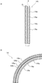
- FIG. 6A is a cross-sectional view showing a bent structure according to a comparative example
- FIG. 6B is a cross-sectional view showing the same at the time of bending.
- the bending structure 1A according to the comparative example is formed of only a close contact spring, and is capable of bending and restricting compression.
- a gap 1Ab is formed between the winding portions 1Aa even at the central portion inside and outside the bending of the bending structure 1.
- the length of the axis O of the bent structure 1 and the amount of movement of the flexible member 3 passing on the axis O are increased by the gap 1Ab.
- the bending structure 1 of the present embodiment is a bending structure that can be bent with the flexible member 3 by inserting the flexible member 3 movably in the axial direction, and is wound in a coil shape.
- An outer coil portion 5 made of a wire 5a having a plurality of winding portions 5b in the axial direction and a wire material 7a wound in a coil shape and having a plurality of winding portions 7b in the axial direction.
- the outer coil portion 5 has a plurality of gaps 5c separating adjacent winding portions 5b.
- the inner coil portion 7 has winding portions 7b provided corresponding to the gaps 5c of the outer coil portion 5. While being in contact with the adjacent winding portions 5b of the portion 5, it is fitted between the adjacent winding portions 5b.
- bent structure 1 is configured with the inner coil portion 7 positioned inside the outer coil portion 5, the structure can be simplified.
- the winding portion 7b of the inner coil portion 7 regulates the compression of the gap 5c of the outer coil portion 5, and the compression is suppressed as a whole. Is done. For this reason, the bending structure 1 can secure rigidity in the axial direction that does not compress the joint function unit.
- the gap 5c of the outer coil portion 5 is reduced inside the bend, and the inner coil portion 7 is displaced outside the bend. Is allowed, sufficient flexibility for bending together with the joint function part can be ensured even if the rigidity in the axial direction is ensured.
- the bending structure 1 can simplify the structure while stabilizing the bending operation, the operation stability of a device having a joint function unit such as a robot, a manipulator, or an actuator is improved. It is possible to secure.
- the gap 5c of the outer coil portion 5 becomes smaller inside the bend and the gap 5c of the outer coil portion 5 becomes larger outside the bend.
- the length at O does not change as compared with the straight state, and the moving amount of the flexible member 3 can be reliably kept constant.
- the stability of the operation of the flexible member 3 can be ensured, and further, the stability of the operation of the device having the joint function unit can be further ensured.
- the movable length (displacement amount) in which the inner coil portion 7 can move in the radial direction with respect to the axis O of the outer coil portion 5 is (diameter of the outer coil portion ⁇ diameter of the inner coil portion). Of the inner coil portion 7 can be prevented from falling off from the outer coil portion 5.
- the movement of the inner coil portion 7 is regulated by the flexible member 3 as a regulating member so that the movable length is less than half of (diameter of the outer coil portion ⁇ diameter of the inner coil portion). Therefore, it is possible to easily prevent the inner coil portion 7 from falling off without changing the shapes of the inner coil portion 7 and the outer coil portion 5.
- the bending structure 1 is inserted through the flexible member 3 so as to be movable in the axial direction and can be bent together with the flexible member 3, the flexible member 3 is used in a mode of guiding the flexible member 3. The falling off of the inner coil part 7 can be prevented.
- the bent structure 1 can be bent smoothly.
- the inner coil portion 7 and the outer coil portion 5 are formed separately, and the inner coil portion 7 is screwed into the outer coil portion 5, so that the assembly is easy. Further, by changing the characteristics of one or both of the inner coil portion 7 and the outer coil portion 5, the characteristics of the bent structure 1 can be easily changed.
- the adjacent winding portion 5b of the outer coil portion 5 comes into contact with the inside of the bending, so that the amount of movement of the flexible member 3 changes.
- the operator of the joint function can be notified that the joint is bent at a predetermined angle or more.
- FIG. 7 is an enlarged sectional view showing a part of the bent structure according to the second embodiment.
- components corresponding to those in the first embodiment are denoted by the same reference numerals, and redundant description will be omitted.
- the wire diameter d1 of the wire 5a of the outer coil 5 and the wire diameter d2 of the wire 7a of the inner coil 7 are different.
- the wire diameter d1 of the outer coil portion 5 is larger than the wire diameter d2 of the inner coil portion 7.
- the wire diameter d1 of the outer coil part 5 can be smaller than the wire diameter d2 of the inner coil part 7.
- the bent structure 1 can provide the same operation and effect as those of the first embodiment even if the wire diameter d1 of the outer coil portion 5 and the wire diameter d2 of the inner coil portion 7 are different. Further, by making the wire diameter d2 different from the wire diameter d1, the free length and characteristics of the bent structure 1 can be adjusted.
- FIG. 8 is an enlarged cross-sectional view showing a part of the bent structure according to the third embodiment.
- the same components as those in the first embodiment are denoted by the same reference numerals, and the description thereof will not be repeated.
- the winding 7 b of the inner coil 7 contacts the winding 5 b adjacent to the outer coil 5 in a part of the outer coil 5 in the axial direction. 5b.
- the inner coil portion 7 is formed so that the center diameter D2 (see FIG. 1) gradually decreases in the axial direction. Accordingly, as described above, the inner coil portion 7 is fitted between the adjacent winding portions 5b of the outer coil portion 5 only at a part in the axial direction.
- the inner coil portion 7 and the outer coil portion 5 are each a close contact coil, and the gap 5c between the outer coil portions 5 decreases as the center diameter D2 of the inner coil portion 7 decreases.
- the winding structure 7b of the inner coil portion 7 is fitted between the adjacent winding portions 5b of the outer coil portion 5 only at a part of the outer coil portion 5 in the axial direction, so that the bent structure 1, the free length and characteristics can be adjusted.
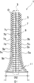
- FIG. 9 is a cross-sectional view illustrating a bent structure according to the fourth embodiment.
- the same reference numerals are given to the components corresponding to those in the first embodiment, and the duplicate description will be omitted.
- the bent structure 1 according to the fourth embodiment is provided with an enlarged diameter portion 11 that gradually increases in diameter in a part of the axial direction.
- an enlarged diameter portion 11 is provided at one end of the bent structure 1 in the axial direction.
- the enlarged diameter portion 11 can be provided at an intermediate portion or the other end of the bent structure 1 in the axial direction.
- both the center diameters D1 and D2 of the outer coil portion 5 and the inner coil portion 7 gradually increase, and the winding portion 7b of the inner coil portion 7 comes into contact with the adjacent winding portion 5b of the outer coil portion 5. The state of fitting between the winding portions 5b is maintained.
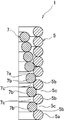
- FIG. 10 is an enlarged sectional view showing a part of the bent structure according to the fifth embodiment.
- components corresponding to those in the first embodiment are denoted by the same reference numerals, and redundant description will be omitted.
- the bent structure 1 of the fifth embodiment has the outer coil portion 5 and the inner coil portion 7 each composed of two coil portions.
- the outer coil portion 5 is configured by the first outer coil portion 13 and the second outer coil portion 15, and the inner coil portion 7 is configured by the first inner coil portion 17 and the second inner coil portion 19. .
- the first outer coil portion 13 and the second outer coil portion 15 are alternately wound in the axial direction with winding portions 13a and 15a, and the first inner coil portion 17 and the second inner coil portion 19 are also alternately wound in the axial direction. Parts 17a and 19a are located.
- the winding portions 13a, 15a of the first outer coil portion 13 and the second outer coil portion 15 are adjacent in the axial direction, and a gap 5c is formed between the adjacent winding portions 13a, 15a. I have.
- the winding part 17a of the first inner coil part 17 and the winding part 19a of the second inner coil part 19 of the inner coil part 7 contact the winding parts 13a and 15a of the first outer coil part 13 and the second outer coil part 15, respectively. While being fitted between the winding portions 13a and 15a.
- the number of the coil portions constituting the outer coil portion 5 and the inner coil portion 7 can be changed. Further, only one of the outer coil part 5 and the inner coil part 7 may be constituted by a plurality of coil parts.
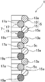
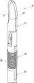
- FIG. 11 is a perspective view showing a part of a robot forceps to which a bending structure is applied according to a sixth embodiment of the present invention
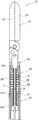
- FIG. 12 is a cross-sectional view thereof
- FIG. 13 is a joint function part of the robot forceps of FIG.
- FIG. 14 is a sectional view of the same.
- the same components as those in the first embodiment are denoted by the same reference numerals, and the description thereof will not be repeated.
- the robot forceps 21 of the present embodiment constitutes the distal end of a robot arm of a surgical robot that is a medical manipulator.
- the robot forceps 21 is an example of a device having a joint function unit.
- the device having the joint function unit is not limited to the medical manipulator as described above. That is, as a device having a joint function unit, a robot having a joint function unit that performs a bending operation and performing an operation by moving the flexible member 3 in the axial direction can be used in various fields.
- the manipulator or the actuator is not particularly limited. In the case of a medical manipulator, an endoscope camera, a manual forceps, and the like that are not attached to the surgical robot are also included.
- the robot forceps 21 of the present embodiment includes a shaft 23, a joint function unit 25, and a grip unit 27 as an end effector for a surgical operation.
- the shaft 23 is formed, for example, in a cylindrical shape.
- a flexible member 3 composed of a drive wire 29 for driving the joint function unit 25 and a push-pull cable for driving the grip unit 27 passes through the shaft 23.
- a grip unit 27 is provided on the distal end side of the shaft 23 via a joint function unit 25.
- the joint function unit 25 includes a base 31, a movable unit 33, a flexible tube 35, and the bent structure 1.
- the base 31 is a cylindrical body formed of resin, metal, or the like, and is attached to the tip of the shaft 23.
- the drive wire 29 is inserted through the base 31 in the axial direction through the through hole 31a, and the flexible member 3 is inserted through the insertion hole 31b in the axial center.
- the movable portion 33 is a columnar body formed of resin, metal, or the like, and is attached to the grip unit 27 described later.
- the distal end of the drive wire 29 is fixed to the movable portion 33.
- the movable portion 33 is displaced with respect to the base 31 by operating the drive wire 29, and directs the grip unit 27 in a desired direction.
- An insertion hole 33 b is provided in the axis of the movable portion 33, and the flexible member 3 is inserted through the insertion hole 33 b.
- the flexible tube 35 is interposed between the base 31 and the movable part 33, and bends according to the displacement of the movable part 33 with respect to the base 31.
- the flexible tube 35 passes the drive wire 29 and the flexible member 3 in the axial direction.
- the flexible tube 35 of this embodiment is constituted by a bellows formed of a tubular body having a corrugated cross section.
- the flexible tube 35 may be a coil spring, a cylindrical body, or the like, and is not particularly limited as long as it has a flexible tube shape.
- the bent structure 1 has the same configuration as that of the first embodiment.
- the bent structure 1 is arranged along the axis of the flexible tube 35, and is provided between the base 31 and the movable part 33. It should be noted that any of the bent structures 1 of the second to fifth embodiments can be applied to the joint function unit 25.
- Both ends of the bent structure 1 are attached to the insertion holes 31 b and 33 b of the base 31 and the movable portion 33, respectively, with the flexible member 3 inserted through the insertion portion 9.
- the bending structure 1 supports the movable portion 33 so as to be unable to move in the axial direction with respect to the base 31, and bends together with the flexible member 3 according to the displacement of the movable portion 33 with respect to the base 31.
- the grip unit 27 has a pair of grip portions 37 pivotally supported on the movable portion 33 of the joint function portion 25 so as to be openable and closable.
- the grip unit 27 is configured such that the flexible member 3 penetrating the joint function unit 25 is connected, and the grip unit 37 is opened and closed by the axial movement (advance / retreat operation) of the flexible member 3.
- the end effector is not limited to the grip unit 27, and may be, for example, scissors, a grip retractor, a needle driver, or the like.
- an operator such as a doctor can cause the grip portion 37 of the grip unit 27 to open and close by moving the flexible member 3 forward and backward.
- the joint function unit 25 is bent, and the grip unit 27 can be directed in a desired direction with respect to the shaft 23. In this state, if the flexible member 3 is moved forward and backward, the gripper 37 of the gripper unit 27 can be opened and closed.
- the opening / closing operation can be performed stably and accurately because the moving amount of the flexible member 3 is constant.
Landscapes
- Engineering & Computer Science (AREA)
- Health & Medical Sciences (AREA)
- Surgery (AREA)
- Life Sciences & Earth Sciences (AREA)
- Robotics (AREA)
- General Health & Medical Sciences (AREA)
- Mechanical Engineering (AREA)
- Molecular Biology (AREA)
- Veterinary Medicine (AREA)
- Medical Informatics (AREA)
- Biomedical Technology (AREA)
- Animal Behavior & Ethology (AREA)
- Nuclear Medicine, Radiotherapy & Molecular Imaging (AREA)
- Public Health (AREA)
- Heart & Thoracic Surgery (AREA)
- Ophthalmology & Optometry (AREA)
- General Engineering & Computer Science (AREA)
- Orthopedic Medicine & Surgery (AREA)
- Rheumatology (AREA)
- Manipulator (AREA)
- Endoscopes (AREA)
- Surgical Instruments (AREA)
- Instruments For Viewing The Inside Of Hollow Bodies (AREA)
Abstract
十分な可撓性と軸方向の剛性とを確保することが可能な屈曲構造体及び関節機能部を提供する。 コイル状に巻かれて軸方向に複数の巻部5bを有する線材5aからなる外コイル部5と、コイル状に巻かれて軸方向に複数の巻部7bを有する線材7aからなり、外コイル部5内に位置する内コイル部7とを備え、外コイル部5は、隣接する巻部5b間を離間させた複数の隙間5cを有し、内コイル部7は、巻部7bが外コイル部5の隙間5cに対応して設けられ、外コイル部5の隣接する巻部5bに接触しつつ当該巻部5b間に嵌合する。
Description
本発明は、ロボット等の関節機能部に供される屈曲構造体及びこれを用いた関節機能部に関する。
各種分野のロボット、マニピュレーター、或はアクチュエータ等には、関節機能部を有するものがある。このような関節機能部に適用される屈曲構造体としては、例えば、特許文献1に記載の可撓性部材がある。
この特許文献1の可撓性部材は、複数のディスク要素を相互に揺動自在に係合して構成され、各ディスク要素の揺動により全体として屈曲動作を行うようになっている。
かかる構成の可撓性部材は、屈曲動作を円滑に行うことができると共に軸方向の圧縮に対する剛性を確保でき、屈曲動作の安定化を図ることができる。
しかし、特許文献1の可撓性部材は、複数のディスク要素を相互に係合するため、構造が煩雑であるという問題があった。
解決しようとする問題点は、屈曲動作の安定化を図ると、構造が煩雑になる点である。
本発明は、屈曲動作の安定化を図りつつ構造を簡素化するために、軸方向に対して屈曲可能な屈曲構造体であって、コイル状に巻かれて前記軸方向に複数の巻部を有する線材からなる外コイル部と、コイル状に巻かれて前記軸方向に複数の巻部を有する線材からなり前記外コイル部内に位置する内コイル部とを備え、前記外コイル部は、前記軸方向で隣接する巻部間を離間させた複数の隙間を有し、前記内コイル部は、前記巻部が前記外コイル部の前記隙間に対応して設けられ前記外コイル部の前記隣接する巻部に接触しつつ当該巻部間に嵌合することを屈曲構造体の最も主な特徴とする。
また、本発明は、上記屈曲構造体を適用した関節機能部であって、基部及び該基部に対して変位する可動部を備え、屈曲構造体は、前記基部と可動部との間に設けられ、前記基部に対する前記可動部の変位に応じて屈曲することを関節機能部の最も主な特徴とする。
本発明によれば、屈曲構造体が内コイル部を外コイル部内に位置させて構成されているため、構造を簡素化することができる。
また、内コイル部の巻部が外コイル部の隣接する巻部に接触しつつそれら隣接する巻部間に嵌合しているので、軸方向の剛性を確保することができる。
また、屈曲時には、屈曲の内側で外コイル部の隙間を小さくしつつ屈曲の外側に内コイル部を変位させ、屈曲の外側で外コイル部の隙間を大きくして内コイル部の変位を許容することで、軸方向の剛性を確保しても十分な可撓性を確保することができる。
結果として、本発明では、屈曲動作の安定化を図りつつ構造を簡素化することが可能となる。
しかも、本発明では、屈曲の内側で外コイル部の隙間が小さくなり、屈曲の外側で外コイル部の隙間が大きくなるので、外コイル部の軸心における長さが直状時と比較して変化せず、内周側に可撓部材を軸方向で移動可能にガイドするように用いる場合、可撓部材の移動量を確実に一定に保つことができる。
屈曲動作の安定化を図りつつ構造を簡素化するという目的を、外コイル部内に内コイル部を位置させた二重コイル形状の屈曲構造体により実現した。
すなわち、屈曲構造体は、軸方向に対して屈曲可能な屈曲構造体であって、コイル状に巻かれて軸方向に複数の巻部を有する線材からなる外コイル部と、コイル状に巻かれて軸方向に複数の巻部を有する線材からなり、外コイル部内に位置する内コイル部とを備える。
外コイル部は、軸方向で隣接する巻部間を離間させた複数の隙間を有し、内コイル部は、巻部が外コイル部の隙間に対応して設けられ、外コイル部の隣接する巻部に接触しつつ当該巻部間に嵌合する。
外コイル部は、軸方向で隣接する巻部の各間に隙間を有してもよいが、軸方向の一部にのみ隙間を有する構成とすることも可能である。
内コイル部が外コイル部の軸心に対して径方向に移動可能な可動長さは、(外コイル部の直径-内コイル部の直径)の半分以下としてもよい。
この場合、可動長さが(外コイル部の直径-内コイル部の直径)の半分以下となるように、内コイル部の移動を規制する規制部材を有する構成としてもよい。
規制部材を可撓部材とし、屈曲構造体を可撓部材を軸方向に移動可能に挿通して可撓部材と共に屈曲可能である構成としてもよい。
また、内コイル部と外コイル部とは、別体又は一体に構成することが可能である。内コイル部と外コイル部とを別体に形成する場合は、内コイル部が外コイル部内に螺合された構成としてもよい。
可撓部材の屈曲構造体を適用した関節機能部は、基部及び該基部に対して変位する可動部を備えた構成としてもよい。この場合、屈曲構造体は、基部と可動部との間に設けられ、基部に対する可動部の変位に応じて屈曲する。
また、関節機能部は、基部及び可動部間に介設された軸方向に伸縮可能な可撓チューブを備えてもよい。この場合、屈曲構造体は、可撓チューブの軸心部に沿って軸方向に配置される。
[屈曲構造体の構造]
図1は、本発明の実施例1に係る可撓部材の屈曲構造体を示す断面図、図2は、同一部を示す拡大図である。
図1は、本発明の実施例1に係る可撓部材の屈曲構造体を示す断面図、図2は、同一部を示す拡大図である。
屈曲構造体1は、例えば各種分野のロボット、マニピュレーター、或はアクチュエータ等の関節機能部に適用されるものである。この屈曲構造体1は、関節機能部の基部及び可動部間に設けられ、屈曲により基部に対して可動部を変位可能に支持する。
本実施例の屈曲構造体1は、二重コイル形状であり、外コイル部5と、内コイル部7とを備えている。この二重コイル形状により、本実施例の屈曲構造体1は、軸方向に対して屈曲可能であって、外力により屈曲する際に屈曲の内径側が収縮しかつ屈曲の外径側が伸長することにより、中心軸又は軸心Oの軸方向長さが屈曲前後及び屈曲中においてほぼ一定であり、非屈曲等の際に軸方向への圧縮を規制する構成となっている。かかる本実施例の屈曲構造体1は、規制部材としての可撓部材3も備えている。
可撓部材3は、屈曲構造体1を軸方向に移動可能に挿通し、詳細は後述するが、内外コイル部5,7の径方向へのずれを規制するものである。本実施例の可撓部材3は、例えば、プッシュプルケーブル等を利用して構成されている。これに応じて、屈曲構造体1は、可撓部材3を軸方向へガイドする機能も有し、関節機能部の屈曲動作に応じて可撓部材3と共に屈曲可能となっている。
なお、屈曲とは、関節機能部又は屈曲構造体1の軸心Oを湾曲又は屈曲させることを意味する。また、可撓部材3は、省略することも可能である。
外コイル部5は、コイルばねであり、コイル状に巻かれた線材5aからなる。従って、外コイル部5は、軸方向に複数の巻部5bを有する。なお、巻部5bは、コイル形状を構成する一巻きを意味する(以下、同じ。)。
線材5aの材質は、金属や樹脂等とすることが可能である。線材5aの断面は、円形に形成されているが、楕円等としてもよい。
外コイル部5の中心径D1は、軸方向の一端から他端に至るまで一定となっている。ただし、外コイル部5の中心径D1は、軸方向で変化させることも可能である。
外コイル部5は、軸方向で隣接する巻部5b間を軸方向で離間させた複数の隙間5cを有している。本実施例の隙間5cは、軸方向で隣接する巻部5bの各間に形成され、全ての隙間5cは、同一の軸方向の寸法を有している。ただし、隙間5cは、軸方向で一部の巻部5b間にのみ設けることも可能である。また、隙間5cの軸方向の寸法を変化させることも可能である。
内コイル部7は、コイルばねであり、軸方向に複数の巻部7bを有するコイル状に巻かれた線材7aからなる。内コイル部7は、外コイル部と同様、線材7aの材質を金属や樹脂とすることが可能であり、線材7aの断面が円形であるが、楕円等とすることも可能である。
この内コイル部7は、外コイル部5の内側に位置し、内周に可撓部材3を挿通するための挿通部9が区画されている。本実施例の内コイル部7は、外コイル部5内に螺合されている。この螺合により、内コイル部7の巻部7bが外コイル部5の隣接する巻部5bの各間に位置している。従って、内コイル部7は、巻部7bが外コイル部5の隙間5cに対応して設けられた構成となっている。
また、内コイル部7の巻部7bは、中心径D2及び線材7aの線径d2の設定により、外コイル部5の隣接する巻部5bに接触しつつ当該巻部5b間に嵌合している。
なお、内コイル部7の中心径D2は、軸方向の一端から他端に至るまで一定となっている。ただし、内コイル部7の中心径D2は、外コイル部5の中心径D1に応じて、軸方向で変化させること等も可能である。
また、線材7aの線径d2は、外コイル部5の線材5aの線径d1と同一になっている。ただし、線材7aの線径d2は、外コイル部5の線材5aの線径d1よりも大きく又は小さく形成してもよい。
内コイル部7は、隣接する巻部7b間を軸方向で離間させた複数の隙間7cを有している。隙間7cは、外コイル部5との螺合に応じ、隣接する巻部7bの各間に形成され、全ての隙間7cは、同一の軸方向の寸法を有している。
なお、外コイル部5及び内コイル部7は、外コイル部5内に内コイル部7が位置していない自由状態で、隣接する巻部5b,7bの各間に隙間5c,7cを有する構成の他、自由状態で隣接する巻部5b,7bが密着した構成(密着ばね)とすることも可能である。さらに、外コイル部5及び内コイル部7の一方のみを密着ばねとすることも可能である。
外コイル部5及び内コイル部7が自由状態で密着ばねである場合は、内コイル部7と外コイル部5とを螺合することにより相互に巻部5b,7b間を離間させ、外コイル部5の隙間5c及び内コイル部7の隙間7cが形成される。この場合、二重コイル形状の屈曲構造体1に初張力を付与することが可能である。
[屈曲構造体の動作]
図3は、図1の屈曲構造体の屈曲状態を示す断面図、図4は、同一部を示す拡大図である。
図3は、図1の屈曲構造体の屈曲状態を示す断面図、図4は、同一部を示す拡大図である。
屈曲構造体1は、図1及び図2のように、軸心O(外コイル部5の軸心でもある)が屈曲していない直状時に、内コイル部7の巻部7bが外コイル部5の隣接する巻部5bに接触しつつそれら隣接する巻部5b間に嵌合している。
このため、屈曲構造体1は、軸方向での圧縮力が作用しても、外コイル部5の隙間5cが圧縮されることを内コイル部7の巻部7bが規制し、全体としての圧縮が抑制される。なお、内コイル部7を基準にすると、内コイル部7の隙間7cが圧縮されるのを外コイル部5の巻部5bが規制することになる。
従って、屈曲構造体1は、自身の圧縮ひいては適用される関節機能部の圧縮を抑制することができる。この結果、可撓部材3の軸方向への移動をガイドする際に、軸心Oの長さ並びに軸心O上を通る可撓部材3の移動量を一定に保つことができ、可撓部材3の動作の安定性を確保することもできる。
図3及び図4のように、屈曲構造体1の軸心Oが屈曲すると、屈曲の内側で外コイル部5の隙間5cが小さくなり、屈曲の外側で外コイル部5の隙間5cが大きくなる。
このとき、屈曲構造体1は、内コイル部7が径方向の外側に変位することにより屈曲を円滑に行うことができる。
すなわち、内コイル部7の各巻部7bは、屈曲構造体1の屈曲の内側で、外コイル部5の隙間5cが小さくなることにより径方向の内側に押し込められる。これに応じ、内コイル部7は、全体として径方向の外側に変位するが、この変位は、内コイル部7の各巻部7bが外コイル部5の大きくなった隙間5cに入り込むようにして許容される。
従って、屈曲構造体1は、軸方向の圧縮を規制することができる構成でありながら、可撓性が阻害されることはない。結果として、屈曲構造体1は、屈曲動作の安定化が図られる。
また、屈曲構造体1が屈曲する際は、上記のように、屈曲の内側で外コイル部5の隙間5cが小さくなり、屈曲の外側で外コイル部5の隙間が大きくなるので、軸心O上で隙間5cの大きさが直状時と比較して変化しないことになる。
従って、屈曲構造体1は、直状時だけでなく屈曲時にも、軸心Oの長さ及び屈曲構造体1の軸心O上を通る可撓部材3の移動量を一定に保つことができ、可撓部材3の動作の安定性を確保することができる。
また、本実施例の屈曲構造体1は、所定角度に屈曲した際に、屈曲の内側で外コイル部5の隣接する巻部5bが接触する(図4参照)。
従って、屈曲構造体1では、巻部5bが接触したときから、軸心O上の長さが大きくなり始める。このため、可撓部材3の移動量の変化により、関節機能部の操作者に所定角度以上に屈曲したことを通知することができる。
かかる屈曲構造体1の屈曲動作時には、可撓部材3により内コイル部7の外コイル部5からの脱落が防止される。
すなわち、上記のように、屈曲構造体1の屈曲時には、内コイル部7の各巻部7bが外コイル部5の大きくなった隙間5cに入り込むようにして、内コイル部7が全体として径方向の外側に変位する。
この変位(内コイル部7が外コイル部5の軸心Oに対して径方向に移動可能な可動長さ)は、(外コイル部の直径-内コイル部の直径)の半分以下となっている。なお、ここでの直径は、外コイル部7及び内コイル部5の中心径D1及びD2を意味する。ただし、直径は、外コイル部7及び内コイル部5の外径又は内径であってもよい。
図5は、内コイル部7の外コイル部5からの脱落を示す概略断面図であり、(A)は脱落前、(B)は脱落後の状態である。
図5のように、直状時に内コイル部7の径方向への移動量Lが(外コイル部5の直径-内コイル部7の直径)の半分(D1-D2)/2を超えると、内コイル部7が外コイル部5を乗り越えて脱落する状態となる。なお、図5において、移動量Lは、内コイル部7の軸心と外コイル部5の軸心とのズレ量として示している。
屈曲構造体1の屈曲時においても、内コイル部7の径方向への移動量Lが(外コイル部5の直径-内コイル部7の直径)の半分(D1-D2)/2を超えると、直状に戻った際に図5のように脱落が生じてしまう結果になるため、本実施例では、内コイル部7が外コイル部5の軸心Oに対して径方向に移動可能な可動長さが、(外コイル部5の直径-内コイル部7の直径)の半分(D1-D2)/2以下となっている。
この可動長さは、本実施例において、可撓部材3が屈曲構造体1を挿通することで設定されている。こうして、本実施例では、可撓部材3により内コイル部7の外コイル部5からの脱落が防止される。ただし、可動長さは、屈曲構造体1が可撓部材3を挿通しない場合や可撓部材3の径が上記可動長さを設定できない程度に細い場合、外コイル部5及び内コイル部7の線径d1及びd2の何れか一方又は双方の設定により設定することも可能である。
[比較例の移動量]
図6(A)は、比較例に係る屈曲構造体を示す断面図、図6(B)は、同屈曲時を示す断面図である。
図6(A)は、比較例に係る屈曲構造体を示す断面図、図6(B)は、同屈曲時を示す断面図である。
比較例に係る屈曲構造体1Aは、密着ばねのみからなっており、屈曲が可能であると共に圧縮が規制されるようになっている。
この屈曲構造体1Aでは、屈曲時に、屈曲の内側で巻部1Aaが接触した状態を維持し、屈曲の外側で巻部1Aa間に隙間が形成される。
この結果、屈曲時には、屈曲構造体1の屈曲内外の中央部でも巻部1Aa間に隙間1Abが形成される。その隙間1Abの分だけ、屈曲構造体1の軸心Oの長さ及び軸心O上を通る可撓部材3の移動量が大きくなる。
このため、比較例では、可撓部材3をガイドする際に、実施例1のように、可撓部材3の動作の安定性を確保することはできないものとなっている。
[実施例1の効果]
以上説明したように、本実施例の屈曲構造体1は、可撓部材3を軸方向に移動可能に挿通して、可撓部材3と共に屈曲可能な屈曲構造体であって、コイル状に巻かれて軸方向に複数の巻部5bを有する線材5aからなる外コイル部5と、コイル状に巻かれて軸方向に複数の巻部7bを有する線材7aからなり、外コイル部5内に位置する内コイル部7とを備える。
以上説明したように、本実施例の屈曲構造体1は、可撓部材3を軸方向に移動可能に挿通して、可撓部材3と共に屈曲可能な屈曲構造体であって、コイル状に巻かれて軸方向に複数の巻部5bを有する線材5aからなる外コイル部5と、コイル状に巻かれて軸方向に複数の巻部7bを有する線材7aからなり、外コイル部5内に位置する内コイル部7とを備える。
外コイル部5は、隣接する巻部5b間を離間させた複数の隙間5cを有し、内コイル部7は、巻部7bが外コイル部5の隙間5cに対応して設けられ、外コイル部5の隣接する巻部5bに接触しつつ、それら隣接する巻部5b間に嵌合する。
従って、屈曲構造体1は、内コイル部7を外コイル部5内に位置させて構成されているため、構造を簡素化することができる。
また、屈曲構造体1は、軸方向での圧縮力が作用しても、外コイル部5の隙間5cが圧縮されることを内コイル部7の巻部7bが規制し、全体として圧縮が抑制される。このため、屈曲構造体1は、関節機能部を圧縮させない程度の軸方向の剛性を確保することができる。
また、屈曲時には、屈曲の内側で外コイル部5の隙間5cを小さくしつつ屈曲の外側に内コイル部7を変位させ、屈曲の外側で外コイル部5の隙間を大きくして内コイル部7の変位を許容することで、軸方向の剛性を確保しても関節機能部と共に屈曲するための十分な可撓性を確保することができる。
結果として、屈曲構造体1は、屈曲動作の安定化を図りつつ構造を簡素化することが可能となるため、ロボット、マニピュレーター、或はアクチュエータ等の関節機能部を有する機器の動作の安定性を確保することが可能となる。
しかも、本実施例の屈曲構造体1は、屈曲の内側で外コイル部5の隙間5cが小さくなり、屈曲の外側で外コイル部5の隙間5cが大きくなるので、外コイル部5の軸心Oにおける長さが直状時と比較して変化せず、可撓部材3の移動量を確実に一定に保つことができる。
このため、可撓部材3の動作の安定性を確保することができ、ひいては関節機能部を有する機器の動作の安定性を、より確保することが可能となる。
また、本実施例では、内コイル部7が外コイル部5の軸心Oに対して径方向に移動可能な可動長さ(変位量)が(外コイル部の直径-内コイル部の直径)の半分以下となっているので、内コイル部7が外コイル部5から脱落することを防止できる。
また、本実施例では、規制部材としての可撓部材3により、可動長さが(外コイル部の直径-内コイル部の直径)の半分以下となるように、内コイル部7の移動を規制するため、内コイル部7及び外コイル部5の形状を変更することなく、容易に内コイル部7の脱落を防止できる。
屈曲構造体1は、可撓部材3を軸方向に移動可能に挿通して、可撓部材3と共に屈曲可能であるため、可撓部材3をガイドする態様において、可撓部材3を利用して内コイル部7の脱落を防止できる。
本実施例では、外コイル部5が軸方向で隣接する巻部5bの各間に隙間5cを有したため、屈曲構造体1を円滑に屈曲させることができる。
本実施例では、内コイル部7と外コイル部5とが別体に形成され、内コイル部7が外コイル部5内に螺合されたため、組み付けが容易である。また、内コイル部7及び外コイル部5の何れか一方又は双方の特性を変更することにより、屈曲構造体1の特性を容易に変更することができる。
また、本実施例の屈曲構造体1は、所定角度に屈曲した際に、屈曲の内側で外コイル部5の隣接する巻部5bが接触するので、可撓部材3の移動量の変化により、関節機能の操作者に所定角度以上に屈曲したことを通知することができる。
図7は、実施例2に係る屈曲構造体の一部を示す拡大断面図である。なお、実施例2では、実施例1と対応する構成に同符号を付して重複した説明を省略する。
実施例2の屈曲構造体1は、外コイル部5の線材5aの線径d1と内コイル部7の線材7aの線径d2とを異ならせたものである。実施例2では、外コイル部5の線径d1を内コイル部7の線径d2よりも大きくしている。なお、外コイル部5の線径d1を内コイル部7の線径d2よりも小さくすることも可能である。
このように、屈曲構造体1は、外コイル部5の線径d1と内コイル部7の線径d2とを異ならせても、実施例1と同様の作用効果を奏することができる。また、線径d2と線径d1とを異ならせることにより、屈曲構造体1の自由長や特性を調整することができる。
図8は、実施例3に係る屈曲構造体の一部を示す拡大断面図である。なお、実施例3では、実施例1と対応する構成に同符号を付して重複した説明を省略する。
実施例3の屈曲構造体1は、外コイル部5の軸方向の一部において、内コイル部7の巻部7bが外コイル部5の隣接する巻部5bに接触しつつそれら隣接する巻部5b間に嵌合する。
すなわち、内コイル部7は、軸方向で漸次中心径D2(図1参照)が小さくなるように形成されている。これに応じて、内コイル部7は、上記のように、軸方向の一部でのみ外コイル部5の隣接する巻部5b間に嵌合している。
なお、本実施例では、内コイル部7及び外コイル部5がそれぞれ密着コイルであり、内コイル部7の中心径D2が小さくなるにつれて、外コイル部5の隙間5cが小さくなっている。
このように構成しても、実施例1と同様の作用効果を奏することができる。加えて、本実施例では、外コイル部5の軸方向の一部でのみ内コイル部7の巻部7bを外コイル部5の隣接する巻部5b間に嵌合させることにより、屈曲構造体1の自由長や特性を調整することができる。
図9は、実施例4に係る屈曲構造体を示す断面図である。なお、実施例4では、実施例1と対応する構成に同符号を付して重複した説明を省略する。
実施例4の屈曲構造体1は、軸方向の一部に漸次拡径する拡径部11を設けたものである。本実施例では、屈曲構造体1の軸方向の一端に拡径部11を設けている。ただし、拡径部11は、屈曲構造体1の軸方向の中間部や他端に設けることも可能である。
拡径部11では、外コイル部5及び内コイル部7の中心径D1及びD2が共に漸次拡大し、且つ内コイル部7の巻部7bが外コイル部5の隣接する巻部5bに接触しつつ巻部5b間に嵌合する状態を維持している。
このように構成しても、実施例1と同様の作用効果を奏することができる。また、拡径部11により屈曲構造体1の特性を調整することができる。
図10は、実施例5に係る屈曲構造体の一部を示す拡大断面図である。なお、実施例5では、実施例1と対応する構成に同符号を付して重複した説明を省略する。
実施例5の屈曲構造体1は、外コイル部5及び内コイル部7をそれぞれ二つのコイル部で構成したものである。具体的には、外コイル部5が第一外コイル部13及び第二外コイル部15で構成され、内コイル部7が第一内コイル部17及び第二内コイル部19で構成されている。
第一外コイル部13及び第二外コイル部15は、軸方向で交互に巻部13a,15aが位置し、第一内コイル部17及び第二内コイル部19も、軸方向で交互に巻部17a,19aが位置する。
すなわち、外コイル部5は、第一外コイル部13及び第二外コイル部15の巻部13a,15aが軸方向で隣接し、それら隣接する巻部13a,15a間に隙間5cが形成されている。
内コイル部7の第一内コイル部17の巻部17a及び第二内コイル部19の巻部19aは、それぞれ第一外コイル部13及び第二外コイル部15の巻部13a,15aに接触しつつそれら巻部13a,15a間に嵌合している。
このように構成しても、実施例1と同様の作用効果を奏することができ、且つ屈曲構造体1の特性や自由長を調整することができる。
なお、外コイル部5及び内コイル部7を構成するコイル部の数は変更することが可能である。また、外コイル部5及び内コイル部7の一方のみを複数のコイル部で構成することも可能である。
図11は、本発明の実施例6に係り、屈曲構造体を適用したロボット鉗子の一部を示す斜視図、図12は、同断面図、図13は、図11のロボット鉗子の関節機能部を示す斜視図、図14は、同断面図である。なお、実施例6では、実施例1と対応する構成に同符号を付して重複した説明を省略する。
本実施例のロボット鉗子21は、医療用マニピュレーターである手術ロボットのロボットアーム先端を構成するものである。
なお、ロボット鉗子21は、関節機能部を有する機器の一例である。関節機能部を有する機器は、上記のとおり医療用マニピュレーターに限られるものではない。すなわち、関節機能部を有する機器としては、屈曲動作を行う関節機能部を有し、且つ可撓部材3を軸方向に移動させて動作等を行うものであれば、他の分野のロボット、各種のマニピュレーター、或はアクチュエータ等、特に限定されるものではない。また、医療用マニピュレーターの場合は、手術ロボットに取り付けない内視鏡カメラや手動鉗子等も含まれる。
本実施例のロボット鉗子21は、シャフト23、関節機能部25、外科手術用のエンドエフェクタとしての把持ユニット27によって構成されている。
シャフト23は、例えば円筒形状に形成されている。シャフト23内には、関節機能部25を駆動するための駆動ワイヤ29や把持ユニット27を駆動するためのプッシュプルケーブルからなる可撓部材3が通っている。シャフト23の先端側には、関節機能部25を介して把持ユニット27が設けられている。
関節機能部25は、基部31と、可動部33と、可撓チューブ35と、屈曲構造体1とを備えている。
基部31は、樹脂や金属等によって形成された円柱体であり、シャフト23の先端に取り付けられている。基部31には、貫通孔31aにより駆動ワイヤ29が軸方向に挿通し、軸心部の挿通孔31bにより可撓部材3を挿通している。
可動部33は、樹脂や金属等によって形成された円柱体であり、後述する把持ユニット27に取り付けられている。可動部33には、駆動ワイヤ29の先端部が固定されている。このため、可動部33は、駆動ワイヤ29の操作により、基部31に対して変位し、把持ユニット27を所望の方向に指向させる。可動部33の軸心部には、挿通孔33bが設けられ、可撓部材3を挿通している。
可撓チューブ35は、基部31と可動部33との間に介設され、基部31に対する可動部33の変位に応じて屈曲する。可撓チューブ35は、駆動ワイヤ29及び可撓部材3を軸方向に通している。
本実施例の可撓チューブ35は、断面波形状の管体からなるベローズによって構成されている。ただし、可撓チューブ35は、コイルばね、筒体等を用いることも可能であり、可撓性を有するチューブ状を呈していれば、特に限定されるものではない。
屈曲構造体1は、実施例1と同一構成である。この屈曲構造体1は、可撓チューブ35の軸心部に沿って配置され、基部31と可動部33との間に設けられている。なお、関節機能部25には、実施例2~5の何れかの屈曲構造体1を適用することも可能である。
屈曲構造体1は、挿通部9に可撓部材3を挿通した状態で、両端が基部31及び可動部33の挿通孔31b及び33bにそれぞれ取り付けられている。これにより、屈曲構造体1は、基部31に対して可動部33を軸方向移動不能に支持し、基部31に対する可動部33の変位に応じて可撓部材3と共に屈曲するようになっている。
把持ユニット27は、関節機能部25の可動部33に対し、一対の把持部37が開閉可能に軸支されている。この把持ユニット27は、関節機能部25を貫通した可撓部材3が接続され、可撓部材3の軸方向移動(進退動作)により、把持部37が開閉するように構成されている。なお、エンドエフェクタとしては、把持ユニット27に限られず、例えば、鋏、把持レトラクタ、及び針ドライバ等とすることも可能である。
かかる構成のロボット鉗子21では、医師等の操作者が可撓部材3を進退させることにより把持ユニット27の把持部37に開閉動作を行わせることができる。
また、操作者が何れか一つ或は複数の駆動ワイヤ29を引くことにより、関節機能部25が屈曲してシャフト23に対して把持ユニット27を所望の方向に指向させることができる。この状態で、可撓部材3を進退させれば、把持ユニット27の把持部37に開閉動作を行わせることができる。
かかる開閉動作は、実施例1で説明したように、可撓部材3の移動量が一定であるため、安定して正確に行わせることができる。
その他、本実施例では、実施例1と同様の作用効果を奏することができる。
1屈曲構造体 3可撓部材 5外コイル部 5a,7a線材 5b,7b巻部 5c隙間 7内コイル部 25関節機能部 27把持ユニット 31基部 33可動部 35可撓チューブ
Claims (11)
- 軸方向に対して屈曲可能な屈曲構造体であって、
コイル状に巻かれて前記軸方向に複数の巻部を有する線材からなる外コイル部と、
コイル状に巻かれて前記軸方向に複数の巻部を有する線材からなり前記外コイル部内に位置する内コイル部とを備え、
前記外コイル部は、前記軸方向で隣接する巻部間を離間させた複数の隙間を有し、
前記内コイル部は、前記巻部が前記外コイル部の前記隙間に対応して設けられ前記外コイル部の前記隣接する巻部に接触しつつ当該巻部間に嵌合する、
ことを特徴とする屈曲構造体。 - 請求項1記載の屈曲構造体であって、
前記外コイル部は、前記軸方向で隣接する巻部の各間に前記隙間を有した、
ことを特徴とする屈曲構造体。 - 請求項1又は2記載の屈曲構造体であって、
前記内コイル部が前記外コイル部の軸心に対して径方向に移動可能な可動長さは、(外コイル部の直径-内コイル部の直径)の半分以下である、
ことを特徴とする屈曲構造体。 - 請求項1~3の何れか一項に記載の屈曲構造体であって、
前記可動長さが(外コイル部の直径-内コイル部の直径)の半分以下となるように、前記内コイル部の移動を規制する規制部材を有する、
ことを特徴とする屈曲構造体。 - 請求項4に記載の屈曲構造体であって、
前記規制部材は可撓部材である、
ことを特徴とする屈曲構造体。 - 請求項5に記載の屈曲構造体であって、
前記可撓部材を前記軸方向に移動可能に挿通して前記可撓部材と共に屈曲可能である、
ことを特徴とする屈曲構造体。 - 請求項1~6の何れか一項に記載の屈曲構造体であって、
前記内コイル部と前記外コイル部とが別体に形成され、前記内コイル部が前記外コイル部内に螺合された、
ことを特徴とする屈曲構造体。 - 請求項1~7の何れか一項に記載の屈曲構造体であって、
前記外コイル部は、所定角度に屈曲した際に、屈曲の内側で隣接する巻部が接触する、
ことを特徴とする屈曲構造体。 - 請求項1~8の何れか一項に記載の屈曲構造体を適用した関節機能部であって、
基部及び該基部に対して変位する可動部を備え、
前記屈曲構造体は、前記基部と可動部との間に設けられ、前記基部に対する前記可動部の変位に応じて屈曲する、
ことを特徴とする関節機能部。 - 請求項9記載の関節機能部であって、
前記基部及び可動部間に介設された前記軸方向に伸縮可能な可撓チューブを備え、
前記屈曲構造体は、前記可撓チューブの軸心部に沿って前記軸方向に配置された、
ことを特徴とする関節機能部。 - 軸方向に対して屈曲可能な屈曲構造体であって、
外力により屈曲する際に該屈曲の内径側が収縮しかつ前記屈曲の外径側が伸長することにより、前記軸方向中心軸の長さが屈曲前後及び屈曲中においてほぼ一定であり、非屈曲の際に前記軸方向への圧縮を規制する、
ことを特徴とする屈曲構造体。
Priority Applications (3)
| Application Number | Priority Date | Filing Date | Title |
|---|---|---|---|
| CN201980052744.9A CN112566759A (zh) | 2018-08-14 | 2019-08-02 | 弯曲结构体及使用了该弯曲结构体的关节功能部 |
| US17/268,929 US20230001590A1 (en) | 2018-08-14 | 2019-08-02 | Bending structure and joint function part |
| EP19850396.3A EP3838518A4 (en) | 2018-08-14 | 2019-08-02 | FLEXIBLE STRUCTURE AND JOINT FUNCTIONAL COMPONENT |
Applications Claiming Priority (4)
| Application Number | Priority Date | Filing Date | Title |
|---|---|---|---|
| JP2018-152642 | 2018-08-14 | ||
| JP2018152642 | 2018-08-14 | ||
| JP2019-017778 | 2019-02-04 | ||
| JP2019017778A JP2020026019A (ja) | 2018-08-14 | 2019-02-04 | 手術支援ロボット用インスツルメント |
Publications (1)
| Publication Number | Publication Date |
|---|---|
| WO2020036085A1 true WO2020036085A1 (ja) | 2020-02-20 |
Family
ID=69620872
Family Applications (1)
| Application Number | Title | Priority Date | Filing Date |
|---|---|---|---|
| PCT/JP2019/030599 WO2020036085A1 (ja) | 2018-08-14 | 2019-08-02 | 屈曲構造体及びこれを用いた関節機能部 |
Country Status (6)
| Country | Link |
|---|---|
| US (2) | US20210307773A1 (ja) |
| EP (2) | EP3838518A4 (ja) |
| JP (4) | JP2020026019A (ja) |
| CN (2) | CN112566759A (ja) |
| TW (1) | TWI720570B (ja) |
| WO (1) | WO2020036085A1 (ja) |
Cited By (1)
| Publication number | Priority date | Publication date | Assignee | Title |
|---|---|---|---|---|
| EP4104983A4 (en) * | 2020-02-13 | 2023-08-09 | NHK Spring Co., Ltd. | FLEXIBLE STRUCTURE AND PART WITH ARTICULATING FUNCTION |
Families Citing this family (10)
| Publication number | Priority date | Publication date | Assignee | Title |
|---|---|---|---|---|
| JP2022073298A (ja) * | 2020-10-30 | 2022-05-17 | 日本発條株式会社 | 屈曲操作機構 |
| JP2022073297A (ja) * | 2020-10-30 | 2022-05-17 | 日本発條株式会社 | 屈曲構造体 |
| CN112809656B (zh) * | 2021-02-08 | 2022-02-18 | 清华大学 | 柔性驱动结构、柔性驱动器及驱动系统 |
| JP2022130106A (ja) * | 2021-02-25 | 2022-09-06 | 日本発條株式会社 | 屈曲構造体及び通電デバイス |
| JP2022171422A (ja) * | 2021-04-30 | 2022-11-11 | 日本発條株式会社 | 屈曲構造体 |
| JP2023079073A (ja) * | 2021-11-26 | 2023-06-07 | 日本発條株式会社 | 屈曲構造体及びその半製品 |
| CN114701583B (zh) * | 2022-04-18 | 2023-02-24 | 东北大学秦皇岛分校 | 一种绳驱柔性双关节仿生蟹及控制方法 |
| CN115005993B (zh) * | 2022-05-31 | 2023-09-22 | 四川省肿瘤医院 | 一种弯曲机构及应用该机构的手术机械臂 |
| JP2024053399A (ja) * | 2022-10-03 | 2024-04-15 | 日本発條株式会社 | 屈曲構造体及びその半製品 |
| WO2024089878A1 (ja) * | 2022-10-28 | 2024-05-02 | 日本発條株式会社 | 屈曲構造体 |
Citations (5)
| Publication number | Priority date | Publication date | Assignee | Title |
|---|---|---|---|---|
| JPH07265323A (ja) * | 1993-12-06 | 1995-10-17 | Ethicon Inc | 手術用留め具及びステープル装置 |
| JPH10165361A (ja) * | 1996-10-08 | 1998-06-23 | Asahi Optical Co Ltd | 内視鏡用処置具 |
| JP2009240774A (ja) * | 2008-03-28 | 2009-10-22 | Olympus Medical Systems Corp | 内視鏡用処置具 |
| JP2009538186A (ja) | 2006-05-23 | 2009-11-05 | ケンブリッジ・エンドスコピック・ディヴァイセス,インコーポレーテッド | 外科用器具 |
| US20110144656A1 (en) * | 2001-02-15 | 2011-06-16 | Hansen Medical, Inc. | Robotically controlled medical instrument |
Family Cites Families (15)
| Publication number | Priority date | Publication date | Assignee | Title |
|---|---|---|---|---|
| DE822044C (de) * | 1949-12-23 | 1951-11-22 | Trippel Hanns | Biegsame Welle fuer die Drehmoment-UEbertragung, insbesondere in Kraftfahrzeugen |
| JPS5279947U (ja) * | 1975-12-12 | 1977-06-15 | ||
| DE69020795T2 (de) * | 1989-05-12 | 1995-11-30 | Machida Endoscope Co Ltd | Krümmungssteuerungsanordnung und die Struktur einer biegsamen Tube. |
| US5271543A (en) * | 1992-02-07 | 1993-12-21 | Ethicon, Inc. | Surgical anastomosis stapling instrument with flexible support shaft and anvil adjusting mechanism |
| DE4305376C1 (de) * | 1993-02-22 | 1994-09-29 | Wolf Gmbh Richard | Schaft für medizinische Instrumente |
| US5405073A (en) * | 1993-12-06 | 1995-04-11 | Ethicon, Inc. | Flexible support shaft assembly |
| US5851212A (en) * | 1997-06-11 | 1998-12-22 | Endius Incorporated | Surgical instrument |
| US20020087048A1 (en) * | 1998-02-24 | 2002-07-04 | Brock David L. | Flexible instrument |
| JP2006230635A (ja) * | 2005-02-24 | 2006-09-07 | Asahi Intecc Co Ltd | 医療用処置具 |
| JP5148936B2 (ja) * | 2006-12-28 | 2013-02-20 | テルモ株式会社 | ガイドワイヤ |
| US8080038B2 (en) * | 2007-08-17 | 2011-12-20 | Jmea Corporation | Dynamic stabilization device for spine |
| US20110152880A1 (en) * | 2009-12-23 | 2011-06-23 | Hansen Medical, Inc. | Flexible and steerable elongate instruments with torsion control |
| JP5436266B2 (ja) * | 2010-02-26 | 2014-03-05 | 朝日インテック株式会社 | 医療用コイル構造体と、その製造方法、並びに医療用コイル構造体を形成して成る医療用内視鏡と、医療用処置具と、超音波診断医療用カテーテルと、光干渉診断医療用カテーテル |
| JP6422148B2 (ja) * | 2014-05-20 | 2018-11-14 | 国立大学法人電気通信大学 | マニピュレータ |
| WO2016129336A1 (ja) * | 2015-02-13 | 2016-08-18 | オリンパス株式会社 | マニピュレータ |
-
2019
- 2019-02-04 JP JP2019017778A patent/JP2020026019A/ja active Pending
- 2019-02-12 JP JP2019022424A patent/JP7096179B2/ja active Active
- 2019-08-02 TW TW108127626A patent/TWI720570B/zh active
- 2019-08-02 EP EP19850396.3A patent/EP3838518A4/en active Pending
- 2019-08-02 EP EP19849797.6A patent/EP3838517A4/en active Pending
- 2019-08-02 WO PCT/JP2019/030599 patent/WO2020036085A1/ja active Search and Examination
- 2019-08-02 CN CN201980052744.9A patent/CN112566759A/zh active Pending
- 2019-08-02 US US17/268,891 patent/US20210307773A1/en active Pending
- 2019-08-02 CN CN201980053995.9A patent/CN112654475A/zh active Pending
- 2019-08-02 US US17/268,929 patent/US20230001590A1/en active Pending
-
2022
- 2022-06-23 JP JP2022101074A patent/JP7373613B2/ja active Active
-
2023
- 2023-07-27 JP JP2023122868A patent/JP7472374B2/ja active Active
Patent Citations (5)
| Publication number | Priority date | Publication date | Assignee | Title |
|---|---|---|---|---|
| JPH07265323A (ja) * | 1993-12-06 | 1995-10-17 | Ethicon Inc | 手術用留め具及びステープル装置 |
| JPH10165361A (ja) * | 1996-10-08 | 1998-06-23 | Asahi Optical Co Ltd | 内視鏡用処置具 |
| US20110144656A1 (en) * | 2001-02-15 | 2011-06-16 | Hansen Medical, Inc. | Robotically controlled medical instrument |
| JP2009538186A (ja) | 2006-05-23 | 2009-11-05 | ケンブリッジ・エンドスコピック・ディヴァイセス,インコーポレーテッド | 外科用器具 |
| JP2009240774A (ja) * | 2008-03-28 | 2009-10-22 | Olympus Medical Systems Corp | 内視鏡用処置具 |
Cited By (1)
| Publication number | Priority date | Publication date | Assignee | Title |
|---|---|---|---|---|
| EP4104983A4 (en) * | 2020-02-13 | 2023-08-09 | NHK Spring Co., Ltd. | FLEXIBLE STRUCTURE AND PART WITH ARTICULATING FUNCTION |
Also Published As
| Publication number | Publication date |
|---|---|
| EP3838517A1 (en) | 2021-06-23 |
| CN112654475A (zh) | 2021-04-13 |
| US20230001590A1 (en) | 2023-01-05 |
| JP2022125093A (ja) | 2022-08-26 |
| EP3838517A4 (en) | 2022-09-14 |
| CN112566759A (zh) | 2021-03-26 |
| JP7373613B2 (ja) | 2023-11-02 |
| TWI720570B (zh) | 2021-03-01 |
| JP7096179B2 (ja) | 2022-07-05 |
| EP3838518A1 (en) | 2021-06-23 |
| EP3838518A4 (en) | 2022-08-10 |
| US20210307773A1 (en) | 2021-10-07 |
| JP2020026019A (ja) | 2020-02-20 |
| JP2023153901A (ja) | 2023-10-18 |
| TW202009117A (zh) | 2020-03-01 |
| JP2020026021A (ja) | 2020-02-20 |
| JP7472374B2 (ja) | 2024-04-22 |
Similar Documents
| Publication | Publication Date | Title |
|---|---|---|
| WO2020036085A1 (ja) | 屈曲構造体及びこれを用いた関節機能部 | |
| JPWO2019073859A1 (ja) | 医療用マニピュレーターの可撓チューブ及び屈曲構造体 | |
| JP7475858B2 (ja) | 医療用マニピュレーターの可撓チューブ及び屈曲構造体 | |
| JP2019034081A (ja) | 医療用マニピュレーターの屈曲構造体 | |
| WO2021162089A1 (ja) | 屈曲構造体及び関節機能部 | |
| WO2020036081A1 (ja) | 手術支援ロボット用インスツルメント | |
| US20230256625A1 (en) | Joint function unit | |
| WO2019039362A1 (ja) | 医療用マニピュレーターの屈曲構造体 | |
| JP3029671B2 (ja) | 内視鏡 | |
| US20230330871A1 (en) | Bending structural body | |
| JP2019034083A (ja) | 医療用マニピュレーターの可撓チューブ及び屈曲構造体 | |
| WO2023095861A1 (ja) | 屈曲構造体及びその半製品 | |
| JP2019034082A (ja) | 医療用マニピュレーターの可撓チューブ及び屈曲構造体 | |
| EP4331783A1 (en) | Bending structure body | |
| EP4238722A1 (en) | Bending operation mechanism |
Legal Events
| Date | Code | Title | Description |
|---|---|---|---|
| 121 | Ep: the epo has been informed by wipo that ep was designated in this application |
Ref document number: 19850396 Country of ref document: EP Kind code of ref document: A1 |
|
| DPE1 | Request for preliminary examination filed after expiration of 19th month from priority date (pct application filed from 20040101) | ||
| NENP | Non-entry into the national phase |
Ref country code: DE |
|
| ENP | Entry into the national phase |
Ref document number: 2019850396 Country of ref document: EP Effective date: 20210315 |