WO2020031994A1 - 医療用処置具 - Google Patents
医療用処置具 Download PDFInfo
- Publication number
- WO2020031994A1 WO2020031994A1 PCT/JP2019/030807 JP2019030807W WO2020031994A1 WO 2020031994 A1 WO2020031994 A1 WO 2020031994A1 JP 2019030807 W JP2019030807 W JP 2019030807W WO 2020031994 A1 WO2020031994 A1 WO 2020031994A1
- Authority
- WO
- WIPO (PCT)
- Prior art keywords
- microwave
- antenna
- electrode
- medical treatment
- treatment tool
- Prior art date
Links
Images


Classifications
-
- A—HUMAN NECESSITIES
- A61—MEDICAL OR VETERINARY SCIENCE; HYGIENE
- A61B—DIAGNOSIS; SURGERY; IDENTIFICATION
- A61B18/00—Surgical instruments, devices or methods for transferring non-mechanical forms of energy to or from the body
- A61B18/18—Surgical instruments, devices or methods for transferring non-mechanical forms of energy to or from the body by applying electromagnetic radiation, e.g. microwaves
- A61B18/1815—Surgical instruments, devices or methods for transferring non-mechanical forms of energy to or from the body by applying electromagnetic radiation, e.g. microwaves using microwaves
Definitions
- the present invention relates to a medical treatment device characterized in that microwaves can be irradiated from both electrodes.
- microwaves can coagulate (fix) biological tissues such as digestive organs, liver, bladder, prostate, uterus, blood vessels, and intestinal tract at low temperature.
- Various devices for supporting surgery using microwaves have been developed.
- Patent Literature 1 discloses “a power distribution circuit including two distribution lines that branch into two near an input terminal that conducts with an input line and conduct with a corresponding output line at each output terminal. Two connection lines conducting to each of the output terminals of the two distribution lines, an isolation resistor disposed between the two connection lines, and a stub provided at a branch of the two distribution lines And a power distribution circuit characterized by comprising: This patent document discloses a microwave distribution circuit, but does not disclose the configuration of the medical treatment tool of the present invention.
- Patent Literature 2 discloses that “a surgical instrument body having an electrode portion for irradiating a living tissue with microwaves, a microwave oscillator that is built in the surgical instrument body and oscillates microwaves, and that is built in the surgical instrument body.
- An amplifier connected between the electrode unit and the microwave oscillator, and an amplifier that amplifies microwaves from the microwave oscillator and sends the amplified microwave to the electrode unit,
- a variable output matching circuit connected between the amplifier and the electrode section for matching the output impedance of the amplifier and the impedance of the living tissue, and reflected power and incident power between the amplifier and the electrode section.
- a control means for controlling the variable output matching circuit based on the values of the incident power and the reflected power detected by the detection circuit.
- microwave surgical instrument With the al, discloses a microwave surgical instrument. ". Although this patent document discloses a variable output matching circuit for matching the output impedance of an amplifier and the impedance of living tissue, microwave irradiation can be performed from both electrodes of the medical treatment tool of the present invention. And the configuration of the electrodes is not disclosed.
- Patent Document 3 discloses “a set of jaw elements that can pivot with respect to each other and open and close a gap therebetween, a first transmission line structure attached to one of the set of jaw elements adjacent to the gap, and the first transmission.
- a second transmission line structure attached to the other of the set of jaw elements adjacent to the gap opposite the line structure, a coaxial cable transmitting microwave frequency energy, and a power splitter at a distal end of the coaxial cable Wherein the power splitter is arranged to split the microwave frequency energy transmitted by the coaxial cable between the first transmission line structure and the second transmission line structure;
- the line structure and the second transmission line structure comprise unbalanced lossy transmission lines, support the microwave energy as traveling waves, and each of the first transmission lines.
- the second transmission line structure has an electrical length in the traveling wave along a non-resonant to microwave energy, discloses an electrosurgical forceps. " This patent document discloses that microwaves can be irradiated from both electrodes, but does not disclose the configuration of the electrodes of the medical treatment tool of the present invention.
- the inventors of the present invention have conducted intensive studies to solve the above-described problems, and as a result, a structure in which the microwave application antennas are in contact with each other in a state where the first electrode and the second electrode are closed, or a microwave receiver antenna
- the present inventors have found that by employing a structure in which the electrodes come into contact with each other, it is possible to efficiently irradiate the tissue with microwaves radiated from both electrodes, and completed the present invention.
- the present invention includes the following. 1.
- a medical treatment tool A first electrode including the microwave application antenna 1 and the microwave receiver antenna 1; A second electrode including the microwave application antenna 2 and the microwave reception antenna 2 disposed to face the first electrode; and A coaxial cable including a center conductor and an outer conductor, wherein the center conductor is directly or indirectly connected to the microwave applying antenna 1 and the microwave applying antenna 2, and the outer conductor is A microwave receiving antenna 1 and a microwave receiving antenna 2 which are directly or indirectly connected to the
- the microwave applying antenna 1 and the microwave applying antenna 2 are in contact with each other, or the microwave receiving antenna 1 and the microwave
- the receiving antenna 2 is in contact with the antenna
- a medical treatment tool capable of irradiating microwaves from both the first electrode and the second electrode.
- the center conductor has a tip with two branched shapes, and the microwave applying antenna 1 and the microwave applying antenna 2 are directly or indirectly connected to the two branched center conductors.
- the medical treatment tool according to the above item which is connected. 3.
- the microwave applying antenna 1 and the microwave receiving antenna 1 are provided via an insulator or a dielectric, and the microwave applying antenna 1 is provided in the second electrode. 4.
- the tip of the microwave applying antenna 1 and the tip of the microwave receiving antenna 1 are connected, and / or the tip of the microwave applying antenna 2 and the tip of the microwave receiving antenna 2 5.
- the medical treatment device according to any one of items 1 to 4, wherein 6.
- the tip of the microwave applying antenna 1 and the tip of the microwave receiving antenna 1 are connected via a pin, and / or the tip of the microwave applying antenna 2 and the microwave receiving antenna 5.
- the medical treatment tool according to any one of items 1 to 4, wherein a tip of the antenna 2 is connected via a pin. 7.
- a shaft portion having the coaxial cable, and A grip portion having a connector for connecting the coaxial cable
- a shaft rotation knob is provided on the shaft portion.
- a medical treatment tool A first electrode including the microwave application antenna 1 and the microwave receiver antenna 1; A second electrode including the microwave application antenna 2 and the microwave reception antenna 2 disposed to face the first electrode; and A coaxial cable including a center conductor and an outer conductor, wherein the center conductor is directly or indirectly connected to the microwave applying antenna 1 and the microwave applying antenna 2, and the outer conductor is A microwave receiving antenna 1 and a microwave receiving antenna 2 which are directly or indirectly connected to the
- the microwave applying antenna 1 and the microwave receiving antenna 1 are installed via an insulator or a dielectric, and the microwave is applied to the microwave in the second electrode.
- the applying antenna 2 and the microwave receiving antenna 2 are provided via an insulator or a dielectric, and when the first electrode and the second electrode are closed, the microwave applying antenna 1 And the microwave applying antenna 2 is in contact with the A medical treatment tool capable of irradiating microwaves from both the first electrode and the second electrode. 12. 12. The medical treatment tool according to the aforementioned item 11, wherein the first electrode and the second electrode do not use ceramic.
- the medical treatment tool of the present invention can efficiently irradiate the tissue with microwaves radiated from both electrodes.
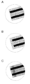
- FIG. 3 is a distal end view of a distal end portion of the medical treatment tool of the present invention. A: In both electrodes, the microwave application antenna and the microwave receiver antenna are separated. B: At both electrodes, the microwave application antenna and the microwave receiver antenna are integrated (connected).
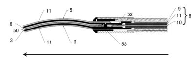
- a cutaway view (the direction of the arrow (long-axis direction) is the tip side and the opposite direction) as viewed from the top surface of the tip portion of the medical treatment tool (structure in which the microwave receiving antennas are in contact with each other) according to another embodiment of the present invention. Is the terminal side). 1 is an overall view of a medical treatment tool of the present invention.
- the medical treatment tool (100) of the present invention relates to a microwave irradiation instrument (particularly, a microwave irradiation surgical instrument) capable of irradiating a tissue with microwaves from both electrodes (see: FIGS. 1 to 5).
- the medical treatment tool (100) of the present invention includes at least the following tip (1).
- the center conductor (10) is connected directly or indirectly to the microwave applying antenna 1 (2) and the microwave applying antenna 2 (5), and the external conductor (9) is connected to the microwave receiving antenna. It is connected directly or indirectly to the hand antenna 1 (3) and the microwave receiver antenna 2 (6).
- the medical treatment tool (100) of the present invention has a microwave applying antenna 1 (2) and a microwave applying antenna 2 (5) in a state where the first electrode (4) and the second electrode (7) are closed. Or a structure in which the microwave receiving antenna 1 (3) and the microwave receiving antenna 2 (6) are in contact (see FIG. 2A), and the first electrode (4) and the second electrode Microwave can be irradiated from both of (7).
- the external conductor (9) As an example of a method of connecting the external conductor (9) to the microwave receiver antenna 1 (3) and the microwave receiver antenna 2 (6), they are connected via pins (12). Thereby, both or one of the microwave receiving antenna 1 (3) and the microwave receiving antenna 2 (6) can be moved, so that the first electrode (4) and / or the second electrode (7) can be moved. can do.
- the pin (12) in the present invention include, but are not particularly limited to, a shape in which two or more members can be directly or indirectly coupled, or a configuration in which two or more members can be rotated around the pin (12). The shape is not particularly limited as long as the shape can be obtained.
- the center conductor (10) has a branched shape with two tips. It has a forked fork shape, and the microwave application antenna 1 (2) and the microwave application antenna 2 (5) are directly or indirectly connected to the two branched center conductors (10), respectively. .
- the microwave applying antenna 1 (2) and the microwave applying antenna 2 (5) are respectively connected to the microwave receiving antenna 1 (3) and the microwave receiving antenna 1 (3) via a dielectric (insulator) (11). It is separated from the wave receiver antenna 2 (6).
- the medical treatment tool (100) of the present invention is not particularly limited as long as it is movable so that a tissue can be grasped in a gap between the first electrode (4) and the second electrode (7).
- forceps see FIG. 2).
- Examples of forceps used in the present invention include forceps known per se, such as Kelly forceps, Kochel forceps, Pean forceps, and Alice forceps, but are not particularly limited.
- the microwave transmitted to the coaxial cable (8) of the medical treatment tool (100) of the present invention is not particularly limited, but is 300 MHz to 300 GHz (wavelength: 1 m to 1 mm), preferably 0.9 GHz to 30 GHz. is there.
- the transmission method can be easily achieved by a method known per se, for example, by connecting to a microwave oscillator that oscillates a microwave known per se, or by incorporating the oscillator in the medical treatment tool (101). be able to.
- the power used in the present invention is 0.1 W to 200 W, preferably 1.0 W to 80 W.
- the coaxial cable (8) used in the present invention is, for example, a conductor center conductor made of copper and a shield tube made of an insulator or a dielectric (eg, made of Teflon (registered trademark) , polyethylene, or the like ) covering the center conductor. And an earth conductor or braided copper wire of an external conductor (conductor) made of copper, stainless steel, brass or the like.
- the coaxial cable (8) may be a known semi-rigid coaxial cable.
- the microwave application antenna 1 (2) and the microwave application antenna 2 (5) of the present invention are not particularly limited as long as they can supply microwaves.
- a wide variety of conductive materials such as silver, copper, gold, iron, titanium, stainless steel, phosphor bronze, and brass can be used.
- silver, copper, gold, stainless steel, brass and the like are exemplified.
- the microwave receiver antenna 1 (3) and the microwave receiver antenna 2 (6) of the present invention are not particularly limited as long as they can receive microwaves.
- a wide variety of conductive materials such as silver, copper, gold, iron, titanium, stainless steel, phosphor bronze, and brass can be used.
- silver, copper, gold, stainless steel, brass and the like are exemplified.
- the shape of the antenna is not particularly limited, but examples include a cone, a triangular pyramid, a quadrangular pyramid, a cylinder, a quadrangular prism, a triangular prism, a sphere, a cube, a rectangular parallelepiped, a blade shape, a round shape, a rod shape, a saw-tooth shape, and the like. Further, the inner surface of the antenna (particularly, the contact surface with the tissue) can be widely applied to a flat type, an uneven type and the like.
- the specific configuration of the microwave application antenna of the present invention is a quadrangular prism, the contact surface with the tissue has a sawtooth shape so that the tissue is not slippery, and the specific configuration of the microwave reception antenna is
- the contact surface with the tissue may have a saw-tooth shape so that the tissue does not slip easily.
- the first electrode (4) of the present invention includes a microwave application antenna 1 (2) and a microwave receiver antenna 1 (3).
- the second electrode (7) of the present invention includes a microwave application antenna 2 (5) and a microwave receiver antenna 2 (6).
- the first electrode (4) and the second electrode (7) are movable (especially forceps) so that the tissue can be grasped in a gap between the two electrodes, and further, if necessary, a coagulation function and / or There is no particular limitation as long as it has a cutting function.
- one or both of the first electrode (4) and the second electrode (7) can be a fixed electrode or a movable electrode.
- the electrode is partially or wholly coated with a coating to which solidified tissue is unlikely to adhere upon contact with tissue.
- the coating is performed with gold, a Teflon-based member, or the like.
- the electrode in the present invention preferably does not use a ceramic member.
- the configuration of the tip of the first electrode (4) and / or the second electrode (7) of the present invention that enables efficient microwave irradiation is as follows. In both electrodes, the microwave application antennas (2, 5) and the microwave reception antennas (3, 6) are separated (preferably separated from the end to the tip) (see FIG. 3A).
- the microwave application antennas (2, 5) and the microwave receiver antennas (3, 6) are integrated (connected, preferably, the microwave application antennas (2, 5) and the microwave receiver).
- the front ends of the antennas (3, 6) are integrated (see FIG. 3B).
- the microwave application antennas (2, 5) and the microwave reception antennas (3, 6) can be manufactured as an integral part, and both end portions affect the microwave irradiation. You may vapor-deposit with a member which does not give.
- the microwave application antennas (2, 5) and the microwave reception antennas (3, 6) are connected via pins (12) and the like (see FIG. 3C).
- the microwave applying antenna 1 (2) and the microwave receiving antenna 1 (3) are installed via an insulator (dielectric) (11).
- the insulator (dielectric) (11) has a shape sandwiched between the microwave applying antenna 1 (2) and the microwave receiving antenna 1 (3) (see FIG. 1).
- the microwave application antenna 1 (2) and the microwave receiver antenna 1 (3) are partially or entirely insulated.
- the microwave application antenna 2 (5) and the microwave reception antenna 2 (6) are installed via an insulator (dielectric) (11). More specifically, the insulator (dielectric) (11) has a shape sandwiched between the microwave applying antenna 2 (5) and the microwave receiving antenna 2 (6) (see FIG. 1). Thereby, the microwave application antenna 2 (5) and the microwave receiver antenna 2 (6) are partially or entirely insulated.
- the insulator / dielectric include PEEK resin, Teflon (registered trademark) , and ceramic.
- the shaft portion (20) (see FIG. 5) of the present invention may have the same structure as the shaft portion of a medical device known per se, but preferably has a coaxial cable (8). Further, the shaft section (20) may have a shaft rotation knob (21). By rotating the shaft rotation knob (21), the tip (1) and the shaft (20) can be rotated.
- the grip portion (30) (see FIG. 5) of the present invention may have the same structure as the grip portion of a medical device known per se, but includes a connector (31), a microwave irradiation switch (32), and an electrode movable switch ( 33).
- a connector 31
- a microwave irradiation switch 32
- an electrode movable switch 33
- the microwave irradiation switch (32) can adjust not only on / off of microwave irradiation but also strength.
- the electrode moving switch (33) can operate opening and closing by both electrodes.
- Example 1 of medical treatment instrument of the present invention is a medical treatment tool having a structure in which the microwave application antennas are in contact with each other as shown in FIG. Each antenna uses stainless steel, and the insulator (dielectric) (11) uses PEEK resin. In both electrodes, the microwave application antenna and the microwave receiver antenna are separated (see FIG. 3A). By coagulating the pig lever with the medical treatment tool of the present example, it was confirmed that the medical treatment tool of the present example could suppress sparks and could uniformly irradiate microwaves.
- Example 2 of medical treatment instrument of the present invention a medical treatment tool having a structure in which antennas for microwave receivers are in contact with each other as shown in FIG.
- Each antenna uses stainless steel, and the insulator (dielectric) (11) uses PEEK resin.
- the microwave application antenna and the microwave receiver antenna are separated (see FIG. 3A).
- the medical treatment device of the present invention has one or more of the following effects. (1) Microwaves radiated from both electrodes can be efficiently radiated to the tissue. (2) Spark can be suppressed without using ceramic members for both electrodes. (3) Microwave can be irradiated substantially uniformly from the surface of the microwave application antenna.
- the present invention it is possible to provide a medical treatment tool capable of efficiently irradiating a tissue with microwaves radiated from both electrodes.
- Electrode movable switch 50 Upper and lower blade mating surface 51: External conductor of coaxial cable and external of electrode Conductor connection point 52: Connection point between the center conductor of the coaxial cable and the center conductor of the electrode 53: A point where the antenna is contacted inside and the center conductor is branched.
Abstract
両電極から照射されるマイクロ波を組織照射するときに、スパークの問題があった。さらに、スパーク解消のために電極にセラミックス部材を使用した場合には、操作中に該セラミックスが脱落する問題があった。これらの問題を解決する医療用処置具を提供する。第1電極(2)と第2電極(5)が閉じた状態において、マイクロ波印加用アンテナ同士が接触する構造又はマイクロ波受手用アンテナ同士が接触する構造を採用することにより、両電極(2,5)から照射されるマイクロ波を組織に効率的に照射することができる。
Description
本発明は、両電極からマイクロ波を照射可能であることを特徴とする医療用処置具に関する。
本出願は、参照によりここに援用されるところの日本出願2018-147403号優先権を請求する。
本出願は、参照によりここに援用されるところの日本出願2018-147403号優先権を請求する。
(マイクロ波を使用したデバイス)
マイクロ波は、消化器、肝臓、膀胱、前立腺、子宮、血管、腸管等の生体組織を低温で凝固(固定化)できることが知られている。そして、マイクロ波を用いた手術支援用の種々のデバイスが開発されている。
マイクロ波は、消化器、肝臓、膀胱、前立腺、子宮、血管、腸管等の生体組織を低温で凝固(固定化)できることが知られている。そして、マイクロ波を用いた手術支援用の種々のデバイスが開発されている。
(先行文献)
マイクロ波を使用したデバイスとして、以下の複数が報告されている。
特許文献1は、「入力線路と導通する入力端子の近傍で2本に分岐すると共に、それぞれの出力端子において対応する出力線路と導通する2本の分配線路を備える電力分配回路であって、前記2本の分配線路の出力端子のそれぞれに導通する2本の接続線路と、前記2本の接続線路の間に配置されるアイソレーション抵抗と、前記2本の分配線路の分岐部に設けられるスタブと、を備えることを特徴とする電力分配回路」を開示している。
本特許文献は、マイクロ波の分配回路を開示しているが、本発明の医療用処置具の構成を開示していない。
マイクロ波を使用したデバイスとして、以下の複数が報告されている。
特許文献1は、「入力線路と導通する入力端子の近傍で2本に分岐すると共に、それぞれの出力端子において対応する出力線路と導通する2本の分配線路を備える電力分配回路であって、前記2本の分配線路の出力端子のそれぞれに導通する2本の接続線路と、前記2本の接続線路の間に配置されるアイソレーション抵抗と、前記2本の分配線路の分岐部に設けられるスタブと、を備えることを特徴とする電力分配回路」を開示している。
本特許文献は、マイクロ波の分配回路を開示しているが、本発明の医療用処置具の構成を開示していない。
特許文献2は、「生体組織にマイクロ波を照射するための電極部を有する手術器本体と、前記手術器本体に内蔵され、マイクロ波を発振するマイクロ波発振器と、前記手術器本体に内蔵され、前記電極部と前記マイクロ波発振器との間に接続されており、前記マイクロ波発振器からのマイクロ波を増幅させて前記電極部に送る増幅器と、を備えた、マイクロ波手術器であって、前記増幅器と前記電極部との間に接続され、前記増幅器の出力インピーダンスと前記生体組織のインピーダンスとを整合させるための可変出力整合回路と、前記増幅器と電極部との間における反射電力及び入射電力を別々に検出する検出回路と、前記検出回路により検出された入射電力および反射電力の値に基づいて前記可変出力整合回路を制御する制御手段と、をさらに備えた、マイクロ波手術器。」を開示している。
本特許文献は、増幅器の出力インピーダンスと生体組織のインピーダンスとを整合させるための可変出力整合回路を開示しているが、本発明の医療用処置具の両電極からマイクロ波を照射可能であること及び電極の構成を開示していない。
本特許文献は、増幅器の出力インピーダンスと生体組織のインピーダンスとを整合させるための可変出力整合回路を開示しているが、本発明の医療用処置具の両電極からマイクロ波を照射可能であること及び電極の構成を開示していない。
特許文献3は、「互いに関して旋回可能でその間の間隙を開閉する1組の顎要素、前記間隙へ隣接する前記1組の顎要素の一方に取り付けられた第1伝送線路構造、前記第1伝送線路構造に対向して前記間隙へ隣接する前記1組の顎要素の他方に取り付けられた第2伝送線路構造、マイクロ波周波数エネルギーを伝達する同軸ケーブル、及び前記同軸ケーブルの先端側にパワー・スプリッタ、を備え、前記パワー・スプリッタは、前記第1伝送線路構造及び前記第2伝送線路構造間で前記同軸ケーブルにより伝達された前記マイクロ波周波数エネルギーを分割するように配列され、各前記第1伝送線路構造及び前記第2伝送線路構造は、不平衡な損失伝送線路からなり、進行波として前記マイクロ波エネルギーを支援し、各前記第1伝送線路構造及び前記第2伝送線路構造は、前記マイクロ波エネルギーへ非共振である前記進行波沿いに電気長を有する、電気外科鉗子」を開示している。
本特許文献は、両電極からマイクロ波を照射可能であることを開示しているが、本発明の医療用処置具の電極の構成を開示していない。
本特許文献は、両電極からマイクロ波を照射可能であることを開示しているが、本発明の医療用処置具の電極の構成を開示していない。
以上により、先行特許文献は、本発明の両電極からマイクロ波が効率的に照射される電極構造を開示又は示唆をしていない。
両電極から照射されるマイクロ波を組織に効率的に照射することは困難であり、スパークの問題があった。さらに、スパーク解消のために電極にセラミック部材を使用した場合には、操作中に該セラミックが脱落する問題があった。
本発明者らは、上記課題を解決するために鋭意研究を重ねた結果、第1電極と第2電極が閉じた状態において、マイクロ波印加用アンテナ同士が接触する構造又はマイクロ波受手用アンテナ同士が接触する構造を採用することにより、両電極から照射されるマイクロ波を組織に効率的に照射することができることを見出して、本発明を完成した。
すなわち本発明は、以下からなる。
1.医療用処置具であって、
マイクロ波印加用アンテナ1及びマイクロ波受手用アンテナ1を含む第1電極、
該第1電極に対向して配置されたマイクロ波印加用アンテナ2及びマイクロ波受手用アンテナ2を含む第2電極、及び、
中心導体及び外部導体を含む同軸ケーブル、ここで、該中心導体は該マイクロ波印加用アンテナ1及び該マイクロ波印加用アンテナ2に直接又は間接的に接続しており、並びに、該外部導体は該マイクロ波受手用アンテナ1及び該マイクロ波受手用アンテナ2に直接又は間接的に接続しており、を含む先端部を有し、
ここで、該第1電極と該第2電極が閉じた状態において、該マイクロ波印加用アンテナ1と該マイクロ波印加用アンテナ2が接触する構造又は該マイクロ波受手用アンテナ1及び該マイクロ波受手用アンテナ2が接触する構造であり、
該第1電極及び該第2電極の両方からマイクロ波を照射可能である医療用処置具。
2.前記中心導体は先端が2本の分岐した形状をしており、ここで、前記マイクロ波印加用アンテナ1及び前記マイクロ波印加用アンテナ2は該2本の分岐した中心導体と直接又は間接的に接続している前項1に記載の医療用処置具。
3.前記マイクロ波印加用アンテナ1及び前記マイクロ波印加用アンテナ2は前記外部導体とピンを介して接続している前項1に記載の医療用処置具。
4.前記第1電極において、前記マイクロ波印加用アンテナ1及び前記マイクロ波受手用アンテナ1は絶縁体又は誘電体を介して設置されており、並びに、前記第2電極において、前記マイクロ波印加用アンテナ2及び前記マイクロ波受手用アンテナ2は絶縁体又は誘電体を介して設置されている前項1~3のいずれか1に記載の医療用処置具。
5.前記マイクロ波印加用アンテナ1の先端及び前記マイクロ波受手用アンテナ1の先端が接続している、並びに/又は、前記マイクロ波印加用アンテナ2の先端及び前記マイクロ波受手用アンテナ2の先端が接続している前項1~4のいずれか1に記載の医療用処置具。
6.前記マイクロ波印加用アンテナ1の先端及び前記マイクロ波受手用アンテナ1の先端がピンを介して接続している、並びに/又は、前記マイクロ波印加用アンテナ2の先端及び前記マイクロ波受手用アンテナ2の先端がピンを介して接続している前項1~4のいずれか1に記載の医療用処置具。
7.前記第1電極が固定電極であり、並びに、前記第2電極が可動電極である前項1~6のいずれか1に記載の医療用処置具。
8.さらに、前記同軸ケーブルを有するシャフト部、及び、
該同軸ケーブルを接続するコネクタを有するグリップ部を有し、
ここで、該コネクタの回転により、前記先端部及び該シャフト部が回転可能である前項1~7のいずれか1に記載の医療用処置具。
9.さらに、シャフト回転用ノブが前記シャフト部に設置されている前項8に記載の医療用処置具。
10.前記第1電極及び前記第2電極ではセラミックを使用しない前項1~9のいずれか1に記載の医療用処処置具。
11.医療用処置具であって、
マイクロ波印加用アンテナ1及びマイクロ波受手用アンテナ1を含む第1電極、
該第1電極に対向して配置されたマイクロ波印加用アンテナ2及びマイクロ波受手用アンテナ2を含む第2電極、及び、
中心導体及び外部導体を含む同軸ケーブル、ここで、該中心導体は該マイクロ波印加用アンテナ1及び該マイクロ波印加用アンテナ2に直接又は間接的に接続しており、並びに、該外部導体は該マイクロ波受手用アンテナ1及び該マイクロ波受手用アンテナ2に直接又は間接的に接続しており、を含む先端部を有し、
ここで、該第1電極において、該マイクロ波印加用アンテナ1及び該マイクロ波受手用アンテナ1は絶縁体又は誘電体を介して設置されており、並びに、該第2電極において、該マイクロ波印加用アンテナ2及び該マイクロ波受手用アンテナ2は絶縁体又は誘電体を介して設置されており、並びに
該第1電極と該第2電極が閉じた状態において、該マイクロ波印加用アンテナ1と該マイクロ波印加用アンテナ2が接触する構造であり、
該第1電極及び該第2電極の両方からマイクロ波を照射可能である医療用処置具。
12.前記第1電極及び前記第2電極ではセラミックを使用しない前項11に記載の医療用処処置具。
本発明の医療用処置具は、両電極から照射されるマイクロ波を組織に効率的に照射することができる。
以下、本発明について図面を参照して説明するが、本発明は図面に記載された医療用処置に限定されるものではない。
(医療用処置具)
本発明の医療用処置具(100)は、両電極から組織にマイクロ波を照射することが可能なマイクロ波照射器具(特に、マイクロ波照射手術器具)に関する(参照:図1~5)。
本発明の医療用処置具(100)は、少なくとも以下の先端部(1)を含む。
マイクロ波印加用アンテナ1(2)及びマイクロ波受手用アンテナ1(3)を含む第1電極(4)。
第1電極(4)に対向して配置されたマイクロ波印加用アンテナ2(5)及びマイクロ波受手用アンテナ2(6)を含む第2電極(7)。
中心導体(10)及び外部導体(9)を含む同軸ケーブル(8)。ここで、中心導体(10)はマイクロ波印加用アンテナ1(2)及びマイクロ波印加用アンテナ2(5)に直接又は間接的に接続しており、並びに、外部導体(9)はマイクロ波受手用アンテナ1(3)及びマイクロ波受手用アンテナ2(6)に直接又は間接的に接続している。
本発明の医療用処置具(100)は、第1電極(4)と第2電極(7)が閉じた状態において、マイクロ波印加用アンテナ1(2)とマイクロ波印加用アンテナ2(5)が接触する構造又はマイクロ波受手用アンテナ1(3)及びマイクロ波受手用アンテナ2(6)が接触する構造であり(参照:図2A)、かつ第1電極(4)及び第2電極(7)の両方からマイクロ波を照射可能である。
外部導体(9)とマイクロ波受手用アンテナ1(3)及びマイクロ波受手用アンテナ2(6)の接続方法の一つの例として、ピン(12)を介して接続している。これにより、マイクロ波受手用アンテナ1(3)及びマイクロ波受手用アンテナ2(6)の両方又は片方は可動できるので、第1電極(4)及び/又は第2電極(7)を可動することができる。
本発明でのピン(12)の例示として、特に限定されないが、2以上の部材を直接又は間接的に結合できる形状、又は、ピン(12)を軸として2以上の部材を回転可能にすることができる形状であれば特に限定されない。
中心導体(10)とマイクロ波印加用アンテナ1(2)及びマイクロ波印加用アンテナ2(5)の接続方法の一つの例として、中心導体(10)は先端が2本の分岐した形状をした2股フォーク形状でおり、マイクロ波印加用アンテナ1(2)及びマイクロ波印加用アンテナ2(5)は、それぞれ、2本の分岐した中心導体(10)と直接又は間接的に接続している。なお、マイクロ波印加用アンテナ1(2)及びマイクロ波印加用アンテナ2(5)は、それぞれ、誘電体(絶縁体)(11)を介して、マイクロ波受手用アンテナ1(3)及びマイクロ波受手用アンテナ2(6)と分離されている。
本発明の医療用処置具(100)は、第1電極(4)及び第2電極(7)である両電極間の隙間に組織を把持できるように可動であれば特に限定されないが、例えば鉗子、鑷子を例示することができる(参照:図2)。鉗子の例としては、本発明で使用する鉗子は、自体公知の鉗子を使用可能であり、ケリー鉗子、コッヘル鉗子、ペアン鉗子、アリス鉗子等を例示することができるが、特に限定されない。
(照射マイクロ波)
本発明の医療用処置具(100)の同軸ケーブル(8)に伝送されるマイクロ波は、特に、限定されないが、300MHz~300GHz(波長:1m~1mm)、好ましくは、0.9GHz~30GHzである。なお、伝送方法は、自体公知の方法、例えば、自体公知のマイクロ波を発振するマイクロ波発振器に接続すること、又は、該発振器を医療用処置具(101)に内蔵することにより容易に達成することができる。
なお、本発明において使用される電力は0.1W~200W、好ましくは1.0W~80Wである。
本発明の医療用処置具(100)の同軸ケーブル(8)に伝送されるマイクロ波は、特に、限定されないが、300MHz~300GHz(波長:1m~1mm)、好ましくは、0.9GHz~30GHzである。なお、伝送方法は、自体公知の方法、例えば、自体公知のマイクロ波を発振するマイクロ波発振器に接続すること、又は、該発振器を医療用処置具(101)に内蔵することにより容易に達成することができる。
なお、本発明において使用される電力は0.1W~200W、好ましくは1.0W~80Wである。
(同軸ケーブル)
本発明で用いられる同軸ケーブル(8)は、例えば、銅からなる導電体の中心導体と、中心導体を覆う絶縁体又は誘電体(例えば、テフロン(登録商標)、ポリエチレン等からなる)のシールドチューブと、銅、ステンレス、真鍮等からなる外部導体(導電体)のアースパイプ又は編組銅線からなる。
なお、同軸ケーブル(8)は、自体公知のセミリジット同軸ケーブルでも良い。
本発明で用いられる同軸ケーブル(8)は、例えば、銅からなる導電体の中心導体と、中心導体を覆う絶縁体又は誘電体(例えば、テフロン(登録商標)、ポリエチレン等からなる)のシールドチューブと、銅、ステンレス、真鍮等からなる外部導体(導電体)のアースパイプ又は編組銅線からなる。
なお、同軸ケーブル(8)は、自体公知のセミリジット同軸ケーブルでも良い。
(アンテナ)
本発明のマイクロ波印加用アンテナ1(2)及びマイクロ波印加用アンテナ2(5)は、マイクロ波を供給することができる材質であれば特に、限定されない。例えば、銀、銅、金、鉄、チタン、ステンレス、リン青銅又は真鍮等広く導電性材料が使用可能である。好適には、銀、銅、金、ステンレス、真鍮等が例示される。
本発明のマイクロ波受手用アンテナ1(3)及びマイクロ波受手用アンテナ2(6)は、マイクロ波を受けることができる材質であれば特に、限定されない。例えば、銀、銅、金、鉄、チタン、ステンレス、リン青銅又は真鍮等広く導電性材料が使用可能である。好適には、銀、銅、金、ステンレス、真鍮等が例示される。
アンテナの形状は、特に限定されないが、円錐、三角錐、四角錐、円柱、四角柱、三角柱、球、立方体、直方体、刃形状、丸型、棒状、のこぎり歯形状等が例示される。さらに、アンテナの内表面(特に、組織との接触面)は、平面型、凹凸型等が広く適用可能である。
本発明のマイクロ波印加用アンテナの具体的な構成は、四角柱であり、組織との接触面は組織が滑りにくいようにのこぎり歯形状であり、マイクロ波受手用アンテナの具体的な構成は、四角柱であり、組織との接触面は組織が滑りにくいようにのこぎり歯形状であってもよい。
(電極)
本発明の第1電極(4)はマイクロ波印加用アンテナ1(2)及びマイクロ波受手用アンテナ1(3)を含む。本発明の第2電極(7)はマイクロ波印加用アンテナ2(5)及びマイクロ波受手用アンテナ2(6)を含む。
さらに、第1電極(4)及び第2電極(7)は、両電極間の隙間に組織を把持できるように可動である構成(特に、鉗子)、さらに必要に応じて、凝固機能及び/又は切断機能を有すれば特に限定されない。また、第1電極(4)又は第2電極(7)のいずれか又は両方を固定電極又は可動電極とすることができる。
電極は、組織との接触において、凝固組織が付着し難いコーティングが一部又は全部にされていることがより好適である。コーティングは、金、テフロン系部材等で行なわれる。これにより、凝固後の組織が付着することなく、連続的に凝固、切断の処理が行える。なお、本発明での電極は、好ましくは、セラミック部材を使用しない。
本発明の第1電極(4)及び/又は第2電極(7)の先端部の効率的なマイクロ波照射可能な構成は、以下の通りである。
両電極では、マイクロ波印加用アンテナ(2、5)とマイクロ波受手用アンテナ(3、6)が分離(好ましくは末端から先端まで分離)されている(参照:図3A)。
両電極では、マイクロ波印加用アンテナ(2、5)とマイクロ波受手用アンテナ(3、6)が一体化(接続、好ましくは、マイクロ波印加用アンテナ(2、5)とマイクロ波受手用アンテナ(3、6)の先端側が一体化)されている(参照:図3B)。
一体化の例示として、マイクロ波印加用アンテナ(2、5)とマイクロ波受手用アンテナ(3、6)を一体の部品として製造することもできるし、両先端部分をマイクロ波照射に影響を与えない部材で蒸着しても良い。
両電極では、マイクロ波印加用アンテナ(2、5)とマイクロ波受手用アンテナ(3、6)がピン(12)等を介して接続されている(参照:図3C)。
第1電極(4)において、マイクロ波印加用アンテナ1(2)及びマイクロ波受手用アンテナ1(3)は絶縁体(誘電体)(11)を介して設置されている。例えば、絶縁体(誘電体)(11)は、マイクロ波印加用アンテナ1(2)とマイクロ波受手用アンテナ1(3)に挟み込まれた形状を有する(参照:図1)。これにより、マイクロ波印加用アンテナ1(2)及びマイクロ波受手用アンテナ1(3)は一部又は全部が絶縁している。
第2電極(7)において、マイクロ波印加用アンテナ2(5)及びマイクロ波受手用アンテナ2(6)は絶縁体(誘電体)(11)を介して設置されている。より詳しくは、絶縁体(誘電体)(11)は、マイクロ波印加用アンテナ2(5)とマイクロ波受手用アンテナ2(6)に挟み込まれた形状を有する(参照:図1)。これにより、マイクロ波印加用アンテナ2(5)及びマイクロ波受手用アンテナ2(6)は一部又は全部が絶縁している。
絶縁体・誘電体の例示として、PEEK樹脂、テフロン(登録商標)、セラミック等を例示することができる。
第2電極(7)において、マイクロ波印加用アンテナ2(5)及びマイクロ波受手用アンテナ2(6)は絶縁体(誘電体)(11)を介して設置されている。より詳しくは、絶縁体(誘電体)(11)は、マイクロ波印加用アンテナ2(5)とマイクロ波受手用アンテナ2(6)に挟み込まれた形状を有する(参照:図1)。これにより、マイクロ波印加用アンテナ2(5)及びマイクロ波受手用アンテナ2(6)は一部又は全部が絶縁している。
絶縁体・誘電体の例示として、PEEK樹脂、テフロン(登録商標)、セラミック等を例示することができる。
(シャフト部)
本発明のシャフト部(20)(参照:図5)は、自体公知の医療器具のシャフト部と同様な構造でも良いが、好ましくは、同軸ケーブル(8)を有する。さらに、シャフト部(20)は、シャフト回転用ノブ(21)を有しても良い。シャフト回転用ノブ(21)を回転させることにより、先端部(1)及びシャフト部(20)を回転させることができる。
本発明のシャフト部(20)(参照:図5)は、自体公知の医療器具のシャフト部と同様な構造でも良いが、好ましくは、同軸ケーブル(8)を有する。さらに、シャフト部(20)は、シャフト回転用ノブ(21)を有しても良い。シャフト回転用ノブ(21)を回転させることにより、先端部(1)及びシャフト部(20)を回転させることができる。
(グリップ部)
本発明のグリップ部(30)(参照:図5)は、自体公知の医療器具のグリップ部と同様な構造でも良いが、コネクタ(31)、マイクロ波照射スイッチ(32)及び電極可動用スイッチ(33)を有しても良い。
コネクタ(31)は、同軸ケーブル(8)と接続することにより、コネクタ(31)の回転により、先端部(1)及びシャフト部(20)が回転可能となる。
マイクロ波照射スイッチ(32)は、マイクロ波照射のon/offだけでなく、強弱も調整可能である。
電極可動用スイッチ(33)は、両電極による開閉を操作することができる。
本発明のグリップ部(30)(参照:図5)は、自体公知の医療器具のグリップ部と同様な構造でも良いが、コネクタ(31)、マイクロ波照射スイッチ(32)及び電極可動用スイッチ(33)を有しても良い。
コネクタ(31)は、同軸ケーブル(8)と接続することにより、コネクタ(31)の回転により、先端部(1)及びシャフト部(20)が回転可能となる。
マイクロ波照射スイッチ(32)は、マイクロ波照射のon/offだけでなく、強弱も調整可能である。
電極可動用スイッチ(33)は、両電極による開閉を操作することができる。
以下、実施例により本発明を具体的に説明するが、本発明はこれらの実施例に限定されるものではない。
(本発明の医療用処置具の実施例1)
本実施例では、図1に示すようなマイクロ波印加用アンテナ同士が接触する構造の医療用処置具である。
各アンテナはステンレスを使用し、絶縁体(誘電体)(11)はPEEK樹脂を使用する。両電極では、マイクロ波印加用アンテナとマイクロ波受手用アンテナが分離されている(参照:図3A)。
本実施例の医療用処置具で豚のレバーを凝固することにより、本実施例の医療用処置具はスパークを抑えることができ、均一にマイクロ波を照射できることを確認した。
本実施例では、図1に示すようなマイクロ波印加用アンテナ同士が接触する構造の医療用処置具である。
各アンテナはステンレスを使用し、絶縁体(誘電体)(11)はPEEK樹脂を使用する。両電極では、マイクロ波印加用アンテナとマイクロ波受手用アンテナが分離されている(参照:図3A)。
本実施例の医療用処置具で豚のレバーを凝固することにより、本実施例の医療用処置具はスパークを抑えることができ、均一にマイクロ波を照射できることを確認した。
(本発明の医療用処置具の実施例2)
本実施例では、図4に示すようなマイクロ波受手用アンテナ同士が接触する構造の医療用処置具である。
各アンテナはステンレスを使用し、絶縁体(誘電体)(11)はPEEK樹脂を使用する。両電極では、マイクロ波印加用アンテナとマイクロ波受手用アンテナが分離されている(参照:図3A)。
本実施例では、図4に示すようなマイクロ波受手用アンテナ同士が接触する構造の医療用処置具である。
各アンテナはステンレスを使用し、絶縁体(誘電体)(11)はPEEK樹脂を使用する。両電極では、マイクロ波印加用アンテナとマイクロ波受手用アンテナが分離されている(参照:図3A)。
本発明の医療用処置具は、以下のいずれか1以上の効果を有する。
(1)両電極から照射されるマイクロ波を組織に効率的に照射することができる。
(2)両電極にセラミック部材を使用しなくてもスパークを抑えることができる。
(3)マイクロ波印加用アンテナの表面から実質的に均一にマイクロ波を照射することができる。
(1)両電極から照射されるマイクロ波を組織に効率的に照射することができる。
(2)両電極にセラミック部材を使用しなくてもスパークを抑えることができる。
(3)マイクロ波印加用アンテナの表面から実質的に均一にマイクロ波を照射することができる。
本発明では、両電極から照射されるマイクロ波を組織に効率的に照射することができる医療用処置具を提供できる。
100:医療用処置具
1:先端部
2:マイクロ波印加用アンテナ1
3:マイクロ波受手用アンテナ1
4:第1電極(固定電極)
5:マイクロ波印加用アンテナ2
6:マイクロ波受手用アンテナ2
7:第2電極(可動電極)
8:同軸ケーブル
9:外部導体
10:中心導体
11:誘電体(絶縁体)
12:ピン
20:シャフト部
21:シャフト回転用ノブ
30:グリップ部
31:コネクタ
32:マイクロ波照射スイッチ
33:電極可動用スイッチ
50:上下刃の合わせ面
51:同軸ケーブルの外部導体と電極の外部導体の接続箇所
52:同軸ケーブルの中心導体と電極の中心導体の接続箇所
53:内部でアンテナを接触させ、中心導体を分岐している箇所
Claims (12)
- 医療用処置具であって、
マイクロ波印加用アンテナ1及びマイクロ波受手用アンテナ1を含む第1電極、
該第1電極に対向して配置されたマイクロ波印加用アンテナ2及びマイクロ波受手用アンテナ2を含む第2電極、及び、
中心導体及び外部導体を含む同軸ケーブル、ここで、該中心導体は該マイクロ波印加用アンテナ1及び該マイクロ波印加用アンテナ2に直接又は間接的に接続しており、並びに、該外部導体は該マイクロ波受手用アンテナ1及び該マイクロ波受手用アンテナ2に直接又は間接的に接続しており、を含む先端部を有し、
ここで、該第1電極と該第2電極が閉じた状態において、該マイクロ波印加用アンテナ1と該マイクロ波印加用アンテナ2が接触する構造又は該マイクロ波受手用アンテナ1及び該マイクロ波受手用アンテナ2が接触する構造であり、
該第1電極及び該第2電極の両方からマイクロ波を照射可能である医療用処置具。
- 前記中心導体は先端が2本の分岐した形状をしており、ここで、前記マイクロ波印加用アンテナ1及び前記マイクロ波印加用アンテナ2は該2本の分岐した中心導体と直接又は間接的に接続している請求項1に記載の医療用処置具。
- 前記マイクロ波印加用アンテナ1及び前記マイクロ波印加用アンテナ2は前記外部導体とピンを介して接続している請求項1に記載の医療用処置具。
- 前記第1電極において、前記マイクロ波印加用アンテナ1及び前記マイクロ波受手用アンテナ1は絶縁体又は誘電体を介して設置されており、並びに、前記第2電極において、前記マイクロ波印加用アンテナ2及び前記マイクロ波受手用アンテナ2は絶縁体又は誘電体を介して設置されている請求項1~3のいずれか1に記載の医療用処置具。
- 前記マイクロ波印加用アンテナ1の先端及び前記マイクロ波受手用アンテナ1の先端が接続している、並びに/又は、前記マイクロ波印加用アンテナ2の先端及び前記マイクロ波受手用アンテナ2の先端が接続している請求項1~4のいずれか1に記載の医療用処置具。
- 前記マイクロ波印加用アンテナ1の先端及び前記マイクロ波受手用アンテナ1の先端がピンを介して接続している、並びに/又は、前記マイクロ波印加用アンテナ2の先端及び前記マイクロ波受手用アンテナ2の先端がピンを介して接続している請求項1~4のいずれか1に記載の医療用処置具。
- 前記第1電極が固定電極であり、並びに、前記第2電極が可動電極である請求項1~6のいずれか1に記載の医療用処置具。
- さらに、前記同軸ケーブルを有するシャフト部、及び、
該同軸ケーブルを接続するコネクタを有するグリップ部を有し、
ここで、該コネクタの回転により、前記先端部及び該シャフト部が回転可能である請求項1~7のいずれか1に記載の医療用処置具。
- さらに、シャフト回転用ノブが前記シャフト部に設置されている請求項8に記載の医療用処置具。
- 前記第1電極及び前記第2電極ではセラミックを使用しない請求項1~9のいずれか1に記載の医療用処処置具。
- 医療用処置具であって、
マイクロ波印加用アンテナ1及びマイクロ波受手用アンテナ1を含む第1電極、
該第1電極に対向して配置されたマイクロ波印加用アンテナ2及びマイクロ波受手用アンテナ2を含む第2電極、及び、
中心導体及び外部導体を含む同軸ケーブル、ここで、該中心導体は該マイクロ波印加用アンテナ1及び該マイクロ波印加用アンテナ2に直接又は間接的に接続しており、並びに、該外部導体は該マイクロ波受手用アンテナ1及び該マイクロ波受手用アンテナ2に直接又は間接的に接続しており、を含む先端部を有し、
ここで、該第1電極において、該マイクロ波印加用アンテナ1及び該マイクロ波受手用アンテナ1は絶縁体又は誘電体を介して設置されており、並びに、該第2電極において、該マイクロ波印加用アンテナ2及び該マイクロ波受手用アンテナ2は絶縁体又は誘電体を介して設置されており、並びに
該第1電極と該第2電極が閉じた状態において、該マイクロ波印加用アンテナ1と該マイクロ波印加用アンテナ2が接触する構造であり、
該第1電極及び該第2電極の両方からマイクロ波を照射可能である医療用処置具。
- 前記第1電極及び前記第2電極ではセラミックを使用しない請求項11に記載の医療用処処置具。
Priority Applications (2)
| Application Number | Priority Date | Filing Date | Title |
|---|---|---|---|
| JP2020501412A JP6784433B2 (ja) | 2018-08-06 | 2019-08-06 | 医療用処置具 |
| EP19847768.9A EP3834761A4 (en) | 2018-08-06 | 2019-08-06 | MEDICAL TREATMENT INSTRUMENT |
Applications Claiming Priority (2)
| Application Number | Priority Date | Filing Date | Title |
|---|---|---|---|
| JP2018147403 | 2018-08-06 | ||
| JP2018-147403 | 2018-08-06 |
Publications (1)
| Publication Number | Publication Date |
|---|---|
| WO2020031994A1 true WO2020031994A1 (ja) | 2020-02-13 |
Family
ID=69414837
Family Applications (1)
| Application Number | Title | Priority Date | Filing Date |
|---|---|---|---|
| PCT/JP2019/030807 WO2020031994A1 (ja) | 2018-08-06 | 2019-08-06 | 医療用処置具 |
Country Status (3)
| Country | Link |
|---|---|
| EP (1) | EP3834761A4 (ja) |
| JP (1) | JP6784433B2 (ja) |
| WO (1) | WO2020031994A1 (ja) |
Cited By (1)
| Publication number | Priority date | Publication date | Assignee | Title |
|---|---|---|---|---|
| JPWO2022185488A1 (ja) * | 2021-03-04 | 2022-09-09 |
Citations (8)
| Publication number | Priority date | Publication date | Assignee | Title |
|---|---|---|---|---|
| JPH11330813A (ja) | 1998-05-20 | 1999-11-30 | Mitsubishi Electric Corp | 電力分配回路および電力増幅器 |
| JP2008054926A (ja) * | 2006-08-31 | 2008-03-13 | Shiga Univ Of Medical Science | マイクロ波手術器 |
| JP2008272472A (ja) * | 2007-04-25 | 2008-11-13 | Covidien Ag | マイクロ波切除のために冷却されるらせん状アンテナ |
| JP2012115384A (ja) | 2010-11-30 | 2012-06-21 | Orient Micro Wave:Kk | マイクロ波手術器 |
| WO2013022077A1 (ja) * | 2011-08-10 | 2013-02-14 | 国立大学法人 滋賀医科大学 | マイクロ波手術器具 |
| JP2016533862A (ja) | 2013-10-07 | 2016-11-04 | クレオ・メディカル・リミテッドCreo Medical Limited | 非共振不平衡な損失伝送線路構造からマイクロ波エネルギーを送達するための電気外科鉗子 |
| WO2017198671A1 (en) * | 2016-05-17 | 2017-11-23 | Creo Medical Limited | Electrosurgical cutting tool |
| JP2018147403A (ja) | 2017-03-08 | 2018-09-20 | 東芝テック株式会社 | 販売データ処理装置及びプログラム |
Family Cites Families (2)
| Publication number | Priority date | Publication date | Assignee | Title |
|---|---|---|---|---|
| US20100249769A1 (en) * | 2009-03-24 | 2010-09-30 | Tyco Healthcare Group Lp | Apparatus for Tissue Sealing |
| EP2520243B1 (en) * | 2009-12-28 | 2015-03-25 | National University Corporation Shiga University OF Medical Science | Medical treatment device |
-
2019
- 2019-08-06 EP EP19847768.9A patent/EP3834761A4/en active Pending
- 2019-08-06 WO PCT/JP2019/030807 patent/WO2020031994A1/ja unknown
- 2019-08-06 JP JP2020501412A patent/JP6784433B2/ja active Active
Patent Citations (8)
| Publication number | Priority date | Publication date | Assignee | Title |
|---|---|---|---|---|
| JPH11330813A (ja) | 1998-05-20 | 1999-11-30 | Mitsubishi Electric Corp | 電力分配回路および電力増幅器 |
| JP2008054926A (ja) * | 2006-08-31 | 2008-03-13 | Shiga Univ Of Medical Science | マイクロ波手術器 |
| JP2008272472A (ja) * | 2007-04-25 | 2008-11-13 | Covidien Ag | マイクロ波切除のために冷却されるらせん状アンテナ |
| JP2012115384A (ja) | 2010-11-30 | 2012-06-21 | Orient Micro Wave:Kk | マイクロ波手術器 |
| WO2013022077A1 (ja) * | 2011-08-10 | 2013-02-14 | 国立大学法人 滋賀医科大学 | マイクロ波手術器具 |
| JP2016533862A (ja) | 2013-10-07 | 2016-11-04 | クレオ・メディカル・リミテッドCreo Medical Limited | 非共振不平衡な損失伝送線路構造からマイクロ波エネルギーを送達するための電気外科鉗子 |
| WO2017198671A1 (en) * | 2016-05-17 | 2017-11-23 | Creo Medical Limited | Electrosurgical cutting tool |
| JP2018147403A (ja) | 2017-03-08 | 2018-09-20 | 東芝テック株式会社 | 販売データ処理装置及びプログラム |
Non-Patent Citations (1)
| Title |
|---|
| See also references of EP3834761A4 * |
Cited By (2)
| Publication number | Priority date | Publication date | Assignee | Title |
|---|---|---|---|---|
| JPWO2022185488A1 (ja) * | 2021-03-04 | 2022-09-09 | ||
| WO2022185488A1 (ja) * | 2021-03-04 | 2022-09-09 | 日機装株式会社 | 医療用処置具 |
Also Published As
| Publication number | Publication date |
|---|---|
| JPWO2020031994A1 (ja) | 2020-08-20 |
| EP3834761A4 (en) | 2021-11-03 |
| EP3834761A1 (en) | 2021-06-16 |
| JP6784433B2 (ja) | 2020-11-11 |
Similar Documents
| Publication | Publication Date | Title |
|---|---|---|
| CN103417294B (zh) | 电外科器械 | |
| EP2641559B1 (en) | Apparatus for tissue sealing | |
| JP6583744B2 (ja) | マイクロ波手術器具 | |
| US9131985B2 (en) | Medical treatment device | |
| GB2522340A (en) | Electrosurgical forceps for delivering RF and/or microwave energy into biological tissue | |
| US9713496B2 (en) | Dual antenna assembly with user-controlled phase shifting | |
| JP2020512038A (ja) | 電気外科用器具 | |
| JP7261492B2 (ja) | 電気外科装置 | |
| CN109303607B (zh) | 用于从非共振不平衡有损耗的传输线结构传递微波能量的电外科钳 | |
| JP2018537135A (ja) | バイオプシー鉗子ツール | |
| WO2020031994A1 (ja) | 医療用処置具 | |
| EP4144315B1 (en) | Electrosurgical instrument, generator and apparatus | |
| WO2018147243A1 (ja) | 医療用処置具 | |
| US20220409229A1 (en) | Medical treatment tool and electromagnetic wave medical system | |
| WO2023140373A1 (ja) | 医療用処置具 | |
| JPWO2021110847A5 (ja) |
Legal Events
| Date | Code | Title | Description |
|---|---|---|---|
| ENP | Entry into the national phase |
Ref document number: 2020501412 Country of ref document: JP Kind code of ref document: A |
|
| 121 | Ep: the epo has been informed by wipo that ep was designated in this application |
Ref document number: 19847768 Country of ref document: EP Kind code of ref document: A1 |
|
| NENP | Non-entry into the national phase |
Ref country code: DE |
|
| ENP | Entry into the national phase |
Ref document number: 2019847768 Country of ref document: EP Effective date: 20210309 |