WO2020031994A1 - Instrument de traitement médical - Google Patents
Instrument de traitement médical Download PDFInfo
- Publication number
- WO2020031994A1 WO2020031994A1 PCT/JP2019/030807 JP2019030807W WO2020031994A1 WO 2020031994 A1 WO2020031994 A1 WO 2020031994A1 JP 2019030807 W JP2019030807 W JP 2019030807W WO 2020031994 A1 WO2020031994 A1 WO 2020031994A1
- Authority
- WO
- WIPO (PCT)
- Prior art keywords
- microwave
- antenna
- electrode
- medical treatment
- treatment tool
- Prior art date
Links
Images


Classifications
-
- A—HUMAN NECESSITIES
- A61—MEDICAL OR VETERINARY SCIENCE; HYGIENE
- A61B—DIAGNOSIS; SURGERY; IDENTIFICATION
- A61B18/00—Surgical instruments, devices or methods for transferring non-mechanical forms of energy to or from the body
- A61B18/18—Surgical instruments, devices or methods for transferring non-mechanical forms of energy to or from the body by applying electromagnetic radiation, e.g. microwaves
- A61B18/1815—Surgical instruments, devices or methods for transferring non-mechanical forms of energy to or from the body by applying electromagnetic radiation, e.g. microwaves using microwaves
Definitions
- the present invention relates to a medical treatment device characterized in that microwaves can be irradiated from both electrodes.
- microwaves can coagulate (fix) biological tissues such as digestive organs, liver, bladder, prostate, uterus, blood vessels, and intestinal tract at low temperature.
- Various devices for supporting surgery using microwaves have been developed.
- Patent Literature 1 discloses “a power distribution circuit including two distribution lines that branch into two near an input terminal that conducts with an input line and conduct with a corresponding output line at each output terminal. Two connection lines conducting to each of the output terminals of the two distribution lines, an isolation resistor disposed between the two connection lines, and a stub provided at a branch of the two distribution lines And a power distribution circuit characterized by comprising: This patent document discloses a microwave distribution circuit, but does not disclose the configuration of the medical treatment tool of the present invention.
- Patent Literature 2 discloses that “a surgical instrument body having an electrode portion for irradiating a living tissue with microwaves, a microwave oscillator that is built in the surgical instrument body and oscillates microwaves, and that is built in the surgical instrument body.
- An amplifier connected between the electrode unit and the microwave oscillator, and an amplifier that amplifies microwaves from the microwave oscillator and sends the amplified microwave to the electrode unit,
- a variable output matching circuit connected between the amplifier and the electrode section for matching the output impedance of the amplifier and the impedance of the living tissue, and reflected power and incident power between the amplifier and the electrode section.
- a control means for controlling the variable output matching circuit based on the values of the incident power and the reflected power detected by the detection circuit.
- microwave surgical instrument With the al, discloses a microwave surgical instrument. ". Although this patent document discloses a variable output matching circuit for matching the output impedance of an amplifier and the impedance of living tissue, microwave irradiation can be performed from both electrodes of the medical treatment tool of the present invention. And the configuration of the electrodes is not disclosed.
- Patent Document 3 discloses “a set of jaw elements that can pivot with respect to each other and open and close a gap therebetween, a first transmission line structure attached to one of the set of jaw elements adjacent to the gap, and the first transmission.
- a second transmission line structure attached to the other of the set of jaw elements adjacent to the gap opposite the line structure, a coaxial cable transmitting microwave frequency energy, and a power splitter at a distal end of the coaxial cable Wherein the power splitter is arranged to split the microwave frequency energy transmitted by the coaxial cable between the first transmission line structure and the second transmission line structure;
- the line structure and the second transmission line structure comprise unbalanced lossy transmission lines, support the microwave energy as traveling waves, and each of the first transmission lines.
- the second transmission line structure has an electrical length in the traveling wave along a non-resonant to microwave energy, discloses an electrosurgical forceps. " This patent document discloses that microwaves can be irradiated from both electrodes, but does not disclose the configuration of the electrodes of the medical treatment tool of the present invention.
- the inventors of the present invention have conducted intensive studies to solve the above-described problems, and as a result, a structure in which the microwave application antennas are in contact with each other in a state where the first electrode and the second electrode are closed, or a microwave receiver antenna
- the present inventors have found that by employing a structure in which the electrodes come into contact with each other, it is possible to efficiently irradiate the tissue with microwaves radiated from both electrodes, and completed the present invention.
- the present invention includes the following. 1.
- a medical treatment tool A first electrode including the microwave application antenna 1 and the microwave receiver antenna 1; A second electrode including the microwave application antenna 2 and the microwave reception antenna 2 disposed to face the first electrode; and A coaxial cable including a center conductor and an outer conductor, wherein the center conductor is directly or indirectly connected to the microwave applying antenna 1 and the microwave applying antenna 2, and the outer conductor is A microwave receiving antenna 1 and a microwave receiving antenna 2 which are directly or indirectly connected to the
- the microwave applying antenna 1 and the microwave applying antenna 2 are in contact with each other, or the microwave receiving antenna 1 and the microwave
- the receiving antenna 2 is in contact with the antenna
- a medical treatment tool capable of irradiating microwaves from both the first electrode and the second electrode.
- the center conductor has a tip with two branched shapes, and the microwave applying antenna 1 and the microwave applying antenna 2 are directly or indirectly connected to the two branched center conductors.
- the medical treatment tool according to the above item which is connected. 3.
- the microwave applying antenna 1 and the microwave receiving antenna 1 are provided via an insulator or a dielectric, and the microwave applying antenna 1 is provided in the second electrode. 4.
- the tip of the microwave applying antenna 1 and the tip of the microwave receiving antenna 1 are connected, and / or the tip of the microwave applying antenna 2 and the tip of the microwave receiving antenna 2 5.
- the medical treatment device according to any one of items 1 to 4, wherein 6.
- the tip of the microwave applying antenna 1 and the tip of the microwave receiving antenna 1 are connected via a pin, and / or the tip of the microwave applying antenna 2 and the microwave receiving antenna 5.
- the medical treatment tool according to any one of items 1 to 4, wherein a tip of the antenna 2 is connected via a pin. 7.
- a shaft portion having the coaxial cable, and A grip portion having a connector for connecting the coaxial cable
- a shaft rotation knob is provided on the shaft portion.
- a medical treatment tool A first electrode including the microwave application antenna 1 and the microwave receiver antenna 1; A second electrode including the microwave application antenna 2 and the microwave reception antenna 2 disposed to face the first electrode; and A coaxial cable including a center conductor and an outer conductor, wherein the center conductor is directly or indirectly connected to the microwave applying antenna 1 and the microwave applying antenna 2, and the outer conductor is A microwave receiving antenna 1 and a microwave receiving antenna 2 which are directly or indirectly connected to the
- the microwave applying antenna 1 and the microwave receiving antenna 1 are installed via an insulator or a dielectric, and the microwave is applied to the microwave in the second electrode.
- the applying antenna 2 and the microwave receiving antenna 2 are provided via an insulator or a dielectric, and when the first electrode and the second electrode are closed, the microwave applying antenna 1 And the microwave applying antenna 2 is in contact with the A medical treatment tool capable of irradiating microwaves from both the first electrode and the second electrode. 12. 12. The medical treatment tool according to the aforementioned item 11, wherein the first electrode and the second electrode do not use ceramic.
- the medical treatment tool of the present invention can efficiently irradiate the tissue with microwaves radiated from both electrodes.
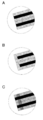
- FIG. 3 is a distal end view of a distal end portion of the medical treatment tool of the present invention. A: In both electrodes, the microwave application antenna and the microwave receiver antenna are separated. B: At both electrodes, the microwave application antenna and the microwave receiver antenna are integrated (connected).
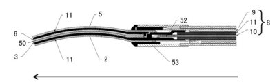
- a cutaway view (the direction of the arrow (long-axis direction) is the tip side and the opposite direction) as viewed from the top surface of the tip portion of the medical treatment tool (structure in which the microwave receiving antennas are in contact with each other) according to another embodiment of the present invention. Is the terminal side). 1 is an overall view of a medical treatment tool of the present invention.
- the medical treatment tool (100) of the present invention relates to a microwave irradiation instrument (particularly, a microwave irradiation surgical instrument) capable of irradiating a tissue with microwaves from both electrodes (see: FIGS. 1 to 5).
- the medical treatment tool (100) of the present invention includes at least the following tip (1).
- the center conductor (10) is connected directly or indirectly to the microwave applying antenna 1 (2) and the microwave applying antenna 2 (5), and the external conductor (9) is connected to the microwave receiving antenna. It is connected directly or indirectly to the hand antenna 1 (3) and the microwave receiver antenna 2 (6).
- the medical treatment tool (100) of the present invention has a microwave applying antenna 1 (2) and a microwave applying antenna 2 (5) in a state where the first electrode (4) and the second electrode (7) are closed. Or a structure in which the microwave receiving antenna 1 (3) and the microwave receiving antenna 2 (6) are in contact (see FIG. 2A), and the first electrode (4) and the second electrode Microwave can be irradiated from both of (7).
- the external conductor (9) As an example of a method of connecting the external conductor (9) to the microwave receiver antenna 1 (3) and the microwave receiver antenna 2 (6), they are connected via pins (12). Thereby, both or one of the microwave receiving antenna 1 (3) and the microwave receiving antenna 2 (6) can be moved, so that the first electrode (4) and / or the second electrode (7) can be moved. can do.
- the pin (12) in the present invention include, but are not particularly limited to, a shape in which two or more members can be directly or indirectly coupled, or a configuration in which two or more members can be rotated around the pin (12). The shape is not particularly limited as long as the shape can be obtained.
- the center conductor (10) has a branched shape with two tips. It has a forked fork shape, and the microwave application antenna 1 (2) and the microwave application antenna 2 (5) are directly or indirectly connected to the two branched center conductors (10), respectively. .
- the microwave applying antenna 1 (2) and the microwave applying antenna 2 (5) are respectively connected to the microwave receiving antenna 1 (3) and the microwave receiving antenna 1 (3) via a dielectric (insulator) (11). It is separated from the wave receiver antenna 2 (6).
- the medical treatment tool (100) of the present invention is not particularly limited as long as it is movable so that a tissue can be grasped in a gap between the first electrode (4) and the second electrode (7).
- forceps see FIG. 2).
- Examples of forceps used in the present invention include forceps known per se, such as Kelly forceps, Kochel forceps, Pean forceps, and Alice forceps, but are not particularly limited.
- the microwave transmitted to the coaxial cable (8) of the medical treatment tool (100) of the present invention is not particularly limited, but is 300 MHz to 300 GHz (wavelength: 1 m to 1 mm), preferably 0.9 GHz to 30 GHz. is there.
- the transmission method can be easily achieved by a method known per se, for example, by connecting to a microwave oscillator that oscillates a microwave known per se, or by incorporating the oscillator in the medical treatment tool (101). be able to.
- the power used in the present invention is 0.1 W to 200 W, preferably 1.0 W to 80 W.
- the coaxial cable (8) used in the present invention is, for example, a conductor center conductor made of copper and a shield tube made of an insulator or a dielectric (eg, made of Teflon (registered trademark) , polyethylene, or the like ) covering the center conductor. And an earth conductor or braided copper wire of an external conductor (conductor) made of copper, stainless steel, brass or the like.
- the coaxial cable (8) may be a known semi-rigid coaxial cable.
- the microwave application antenna 1 (2) and the microwave application antenna 2 (5) of the present invention are not particularly limited as long as they can supply microwaves.
- a wide variety of conductive materials such as silver, copper, gold, iron, titanium, stainless steel, phosphor bronze, and brass can be used.
- silver, copper, gold, stainless steel, brass and the like are exemplified.
- the microwave receiver antenna 1 (3) and the microwave receiver antenna 2 (6) of the present invention are not particularly limited as long as they can receive microwaves.
- a wide variety of conductive materials such as silver, copper, gold, iron, titanium, stainless steel, phosphor bronze, and brass can be used.
- silver, copper, gold, stainless steel, brass and the like are exemplified.
- the shape of the antenna is not particularly limited, but examples include a cone, a triangular pyramid, a quadrangular pyramid, a cylinder, a quadrangular prism, a triangular prism, a sphere, a cube, a rectangular parallelepiped, a blade shape, a round shape, a rod shape, a saw-tooth shape, and the like. Further, the inner surface of the antenna (particularly, the contact surface with the tissue) can be widely applied to a flat type, an uneven type and the like.
- the specific configuration of the microwave application antenna of the present invention is a quadrangular prism, the contact surface with the tissue has a sawtooth shape so that the tissue is not slippery, and the specific configuration of the microwave reception antenna is
- the contact surface with the tissue may have a saw-tooth shape so that the tissue does not slip easily.
- the first electrode (4) of the present invention includes a microwave application antenna 1 (2) and a microwave receiver antenna 1 (3).
- the second electrode (7) of the present invention includes a microwave application antenna 2 (5) and a microwave receiver antenna 2 (6).
- the first electrode (4) and the second electrode (7) are movable (especially forceps) so that the tissue can be grasped in a gap between the two electrodes, and further, if necessary, a coagulation function and / or There is no particular limitation as long as it has a cutting function.
- one or both of the first electrode (4) and the second electrode (7) can be a fixed electrode or a movable electrode.
- the electrode is partially or wholly coated with a coating to which solidified tissue is unlikely to adhere upon contact with tissue.
- the coating is performed with gold, a Teflon-based member, or the like.
- the electrode in the present invention preferably does not use a ceramic member.
- the configuration of the tip of the first electrode (4) and / or the second electrode (7) of the present invention that enables efficient microwave irradiation is as follows. In both electrodes, the microwave application antennas (2, 5) and the microwave reception antennas (3, 6) are separated (preferably separated from the end to the tip) (see FIG. 3A).
- the microwave application antennas (2, 5) and the microwave receiver antennas (3, 6) are integrated (connected, preferably, the microwave application antennas (2, 5) and the microwave receiver).
- the front ends of the antennas (3, 6) are integrated (see FIG. 3B).
- the microwave application antennas (2, 5) and the microwave reception antennas (3, 6) can be manufactured as an integral part, and both end portions affect the microwave irradiation. You may vapor-deposit with a member which does not give.
- the microwave application antennas (2, 5) and the microwave reception antennas (3, 6) are connected via pins (12) and the like (see FIG. 3C).
- the microwave applying antenna 1 (2) and the microwave receiving antenna 1 (3) are installed via an insulator (dielectric) (11).
- the insulator (dielectric) (11) has a shape sandwiched between the microwave applying antenna 1 (2) and the microwave receiving antenna 1 (3) (see FIG. 1).
- the microwave application antenna 1 (2) and the microwave receiver antenna 1 (3) are partially or entirely insulated.
- the microwave application antenna 2 (5) and the microwave reception antenna 2 (6) are installed via an insulator (dielectric) (11). More specifically, the insulator (dielectric) (11) has a shape sandwiched between the microwave applying antenna 2 (5) and the microwave receiving antenna 2 (6) (see FIG. 1). Thereby, the microwave application antenna 2 (5) and the microwave receiver antenna 2 (6) are partially or entirely insulated.
- the insulator / dielectric include PEEK resin, Teflon (registered trademark) , and ceramic.
- the shaft portion (20) (see FIG. 5) of the present invention may have the same structure as the shaft portion of a medical device known per se, but preferably has a coaxial cable (8). Further, the shaft section (20) may have a shaft rotation knob (21). By rotating the shaft rotation knob (21), the tip (1) and the shaft (20) can be rotated.
- the grip portion (30) (see FIG. 5) of the present invention may have the same structure as the grip portion of a medical device known per se, but includes a connector (31), a microwave irradiation switch (32), and an electrode movable switch ( 33).
- a connector 31
- a microwave irradiation switch 32
- an electrode movable switch 33
- the microwave irradiation switch (32) can adjust not only on / off of microwave irradiation but also strength.
- the electrode moving switch (33) can operate opening and closing by both electrodes.
- Example 1 of medical treatment instrument of the present invention is a medical treatment tool having a structure in which the microwave application antennas are in contact with each other as shown in FIG. Each antenna uses stainless steel, and the insulator (dielectric) (11) uses PEEK resin. In both electrodes, the microwave application antenna and the microwave receiver antenna are separated (see FIG. 3A). By coagulating the pig lever with the medical treatment tool of the present example, it was confirmed that the medical treatment tool of the present example could suppress sparks and could uniformly irradiate microwaves.
- Example 2 of medical treatment instrument of the present invention a medical treatment tool having a structure in which antennas for microwave receivers are in contact with each other as shown in FIG.
- Each antenna uses stainless steel, and the insulator (dielectric) (11) uses PEEK resin.
- the microwave application antenna and the microwave receiver antenna are separated (see FIG. 3A).
- the medical treatment device of the present invention has one or more of the following effects. (1) Microwaves radiated from both electrodes can be efficiently radiated to the tissue. (2) Spark can be suppressed without using ceramic members for both electrodes. (3) Microwave can be irradiated substantially uniformly from the surface of the microwave application antenna.
- the present invention it is possible to provide a medical treatment tool capable of efficiently irradiating a tissue with microwaves radiated from both electrodes.
- Electrode movable switch 50 Upper and lower blade mating surface 51: External conductor of coaxial cable and external of electrode Conductor connection point 52: Connection point between the center conductor of the coaxial cable and the center conductor of the electrode 53: A point where the antenna is contacted inside and the center conductor is branched.
Landscapes
- Health & Medical Sciences (AREA)
- Surgery (AREA)
- Life Sciences & Earth Sciences (AREA)
- Biomedical Technology (AREA)
- Medical Informatics (AREA)
- Nuclear Medicine, Radiotherapy & Molecular Imaging (AREA)
- Electromagnetism (AREA)
- Engineering & Computer Science (AREA)
- Physics & Mathematics (AREA)
- Heart & Thoracic Surgery (AREA)
- Otolaryngology (AREA)
- Molecular Biology (AREA)
- Animal Behavior & Ethology (AREA)
- General Health & Medical Sciences (AREA)
- Public Health (AREA)
- Veterinary Medicine (AREA)
- Surgical Instruments (AREA)
Abstract
Il se produit un problème d'étincelles lors de l'irradiation de tissu par des micro-ondes à partir de deux électrodes. Si des éléments en céramique sont utilisés comme électrodes pour résoudre le problème d'étincelles, il se pose le problème que les céramiques peuvent se détacher pendant une opération. La présente invention concerne un instrument de traitement médical qui résout ces problèmes. Selon la présente invention, des micro-ondes peuvent irradier efficacement un tissu à partir d'une première électrode (2) et d'une seconde électrode (5) par l'utilisation d'une structure dans laquelle, lorsque les deux électrodes (2, 5) sont fermées, des antennes pour appliquer des micro-ondes sont en contact entre elles ou des antennes pour recevoir des micro-ondes sont en contact entre elles.
Priority Applications (2)
| Application Number | Priority Date | Filing Date | Title |
|---|---|---|---|
| EP19847768.9A EP3834761A4 (fr) | 2018-08-06 | 2019-08-06 | Instrument de traitement médical |
| JP2020501412A JP6784433B2 (ja) | 2018-08-06 | 2019-08-06 | 医療用処置具 |
Applications Claiming Priority (2)
| Application Number | Priority Date | Filing Date | Title |
|---|---|---|---|
| JP2018147403 | 2018-08-06 | ||
| JP2018-147403 | 2018-08-06 |
Publications (1)
| Publication Number | Publication Date |
|---|---|
| WO2020031994A1 true WO2020031994A1 (fr) | 2020-02-13 |
Family
ID=69414837
Family Applications (1)
| Application Number | Title | Priority Date | Filing Date |
|---|---|---|---|
| PCT/JP2019/030807 WO2020031994A1 (fr) | 2018-08-06 | 2019-08-06 | Instrument de traitement médical |
Country Status (3)
| Country | Link |
|---|---|
| EP (1) | EP3834761A4 (fr) |
| JP (1) | JP6784433B2 (fr) |
| WO (1) | WO2020031994A1 (fr) |
Cited By (1)
| Publication number | Priority date | Publication date | Assignee | Title |
|---|---|---|---|---|
| JPWO2022185488A1 (fr) * | 2021-03-04 | 2022-09-09 |
Citations (8)
| Publication number | Priority date | Publication date | Assignee | Title |
|---|---|---|---|---|
| JPH11330813A (ja) | 1998-05-20 | 1999-11-30 | Mitsubishi Electric Corp | 電力分配回路および電力増幅器 |
| JP2008054926A (ja) * | 2006-08-31 | 2008-03-13 | Shiga Univ Of Medical Science | マイクロ波手術器 |
| JP2008272472A (ja) * | 2007-04-25 | 2008-11-13 | Covidien Ag | マイクロ波切除のために冷却されるらせん状アンテナ |
| JP2012115384A (ja) | 2010-11-30 | 2012-06-21 | Orient Micro Wave:Kk | マイクロ波手術器 |
| WO2013022077A1 (fr) * | 2011-08-10 | 2013-02-14 | 国立大学法人 滋賀医科大学 | Instrument chirurgical à micro-ondes |
| JP2016533862A (ja) | 2013-10-07 | 2016-11-04 | クレオ・メディカル・リミテッドCreo Medical Limited | 非共振不平衡な損失伝送線路構造からマイクロ波エネルギーを送達するための電気外科鉗子 |
| WO2017198671A1 (fr) * | 2016-05-17 | 2017-11-23 | Creo Medical Limited | Outil de coupe électrochirurgical |
| JP2018147403A (ja) | 2017-03-08 | 2018-09-20 | 東芝テック株式会社 | 販売データ処理装置及びプログラム |
Family Cites Families (2)
| Publication number | Priority date | Publication date | Assignee | Title |
|---|---|---|---|---|
| US20100249769A1 (en) * | 2009-03-24 | 2010-09-30 | Tyco Healthcare Group Lp | Apparatus for Tissue Sealing |
| WO2011081196A1 (fr) * | 2009-12-28 | 2011-07-07 | 国立大学法人 滋賀医科大学 | Dispositif de traitement médical |
-
2019
- 2019-08-06 EP EP19847768.9A patent/EP3834761A4/fr active Pending
- 2019-08-06 JP JP2020501412A patent/JP6784433B2/ja active Active
- 2019-08-06 WO PCT/JP2019/030807 patent/WO2020031994A1/fr unknown
Patent Citations (8)
| Publication number | Priority date | Publication date | Assignee | Title |
|---|---|---|---|---|
| JPH11330813A (ja) | 1998-05-20 | 1999-11-30 | Mitsubishi Electric Corp | 電力分配回路および電力増幅器 |
| JP2008054926A (ja) * | 2006-08-31 | 2008-03-13 | Shiga Univ Of Medical Science | マイクロ波手術器 |
| JP2008272472A (ja) * | 2007-04-25 | 2008-11-13 | Covidien Ag | マイクロ波切除のために冷却されるらせん状アンテナ |
| JP2012115384A (ja) | 2010-11-30 | 2012-06-21 | Orient Micro Wave:Kk | マイクロ波手術器 |
| WO2013022077A1 (fr) * | 2011-08-10 | 2013-02-14 | 国立大学法人 滋賀医科大学 | Instrument chirurgical à micro-ondes |
| JP2016533862A (ja) | 2013-10-07 | 2016-11-04 | クレオ・メディカル・リミテッドCreo Medical Limited | 非共振不平衡な損失伝送線路構造からマイクロ波エネルギーを送達するための電気外科鉗子 |
| WO2017198671A1 (fr) * | 2016-05-17 | 2017-11-23 | Creo Medical Limited | Outil de coupe électrochirurgical |
| JP2018147403A (ja) | 2017-03-08 | 2018-09-20 | 東芝テック株式会社 | 販売データ処理装置及びプログラム |
Non-Patent Citations (1)
| Title |
|---|
| See also references of EP3834761A4 * |
Cited By (2)
| Publication number | Priority date | Publication date | Assignee | Title |
|---|---|---|---|---|
| JPWO2022185488A1 (fr) * | 2021-03-04 | 2022-09-09 | ||
| WO2022185488A1 (fr) * | 2021-03-04 | 2022-09-09 | 日機装株式会社 | Instrument de traitement médical |
Also Published As
| Publication number | Publication date |
|---|---|
| EP3834761A1 (fr) | 2021-06-16 |
| JPWO2020031994A1 (ja) | 2020-08-20 |
| JP6784433B2 (ja) | 2020-11-11 |
| EP3834761A4 (fr) | 2021-11-03 |
Similar Documents
| Publication | Publication Date | Title |
|---|---|---|
| CN103417294B (zh) | 电外科器械 | |
| EP2641559B1 (fr) | Appareil pour l'étanchéité de tissus | |
| JP6583744B2 (ja) | マイクロ波手術器具 | |
| US9131985B2 (en) | Medical treatment device | |
| JP7261492B2 (ja) | 電気外科装置 | |
| GB2522340A (en) | Electrosurgical forceps for delivering RF and/or microwave energy into biological tissue | |
| US9713496B2 (en) | Dual antenna assembly with user-controlled phase shifting | |
| JP2020512038A (ja) | 電気外科用器具 | |
| CN109303607B (zh) | 用于从非共振不平衡有损耗的传输线结构传递微波能量的电外科钳 | |
| JP2018537135A (ja) | バイオプシー鉗子ツール | |
| WO2020031994A1 (fr) | Instrument de traitement médical | |
| EP4144315B1 (fr) | Instrument électrochirurgical, générateur et appareil | |
| WO2018147243A1 (fr) | Outil de traitement médical | |
| US20220409229A1 (en) | Medical treatment tool and electromagnetic wave medical system | |
| WO2023140373A1 (fr) | Instrument de traitement médical | |
| JPWO2021110847A5 (fr) |
Legal Events
| Date | Code | Title | Description |
|---|---|---|---|
| ENP | Entry into the national phase |
Ref document number: 2020501412 Country of ref document: JP Kind code of ref document: A |
|
| 121 | Ep: the epo has been informed by wipo that ep was designated in this application |
Ref document number: 19847768 Country of ref document: EP Kind code of ref document: A1 |
|
| NENP | Non-entry into the national phase |
Ref country code: DE |
|
| ENP | Entry into the national phase |
Ref document number: 2019847768 Country of ref document: EP Effective date: 20210309 |