EP3834761A1 - Medical treatment instrument - Google Patents
Medical treatment instrument Download PDFInfo
- Publication number
- EP3834761A1 EP3834761A1 EP19847768.9A EP19847768A EP3834761A1 EP 3834761 A1 EP3834761 A1 EP 3834761A1 EP 19847768 A EP19847768 A EP 19847768A EP 3834761 A1 EP3834761 A1 EP 3834761A1
- Authority
- EP
- European Patent Office
- Prior art keywords
- microwave
- electrode
- antenna
- medical treatment
- treatment instrument
- Prior art date
- Legal status (The legal status is an assumption and is not a legal conclusion. Google has not performed a legal analysis and makes no representation as to the accuracy of the status listed.)
- Pending
Links
- 239000000919 ceramic Substances 0.000 claims abstract description 8
- 239000004020 conductor Substances 0.000 claims description 46
- 239000012212 insulator Substances 0.000 claims description 20
- 239000000463 material Substances 0.000 abstract description 4
- 210000001519 tissue Anatomy 0.000 description 20
- 230000005540 biological transmission Effects 0.000 description 11
- 230000005855 radiation Effects 0.000 description 10
- RYGMFSIKBFXOCR-UHFFFAOYSA-N Copper Chemical compound [Cu] RYGMFSIKBFXOCR-UHFFFAOYSA-N 0.000 description 8
- 229910001220 stainless steel Inorganic materials 0.000 description 7
- 239000010935 stainless steel Substances 0.000 description 7
- 229910052802 copper Inorganic materials 0.000 description 6
- 239000010949 copper Substances 0.000 description 6
- 238000000034 method Methods 0.000 description 6
- 229910001369 Brass Inorganic materials 0.000 description 5
- 239000010951 brass Substances 0.000 description 5
- PCHJSUWPFVWCPO-UHFFFAOYSA-N gold Chemical compound [Au] PCHJSUWPFVWCPO-UHFFFAOYSA-N 0.000 description 5
- 229910052737 gold Inorganic materials 0.000 description 5
- 239000010931 gold Substances 0.000 description 5
- XEEYBQQBJWHFJM-UHFFFAOYSA-N Iron Chemical compound [Fe] XEEYBQQBJWHFJM-UHFFFAOYSA-N 0.000 description 4
- BQCADISMDOOEFD-UHFFFAOYSA-N Silver Chemical compound [Ag] BQCADISMDOOEFD-UHFFFAOYSA-N 0.000 description 4
- 230000001678 irradiating effect Effects 0.000 description 4
- 229910052709 silver Inorganic materials 0.000 description 4
- 239000004332 silver Substances 0.000 description 4
- 239000004696 Poly ether ether ketone Substances 0.000 description 3
- 229920006362 Teflon® Polymers 0.000 description 3
- JUPQTSLXMOCDHR-UHFFFAOYSA-N benzene-1,4-diol;bis(4-fluorophenyl)methanone Chemical compound OC1=CC=C(O)C=C1.C1=CC(F)=CC=C1C(=O)C1=CC=C(F)C=C1 JUPQTSLXMOCDHR-UHFFFAOYSA-N 0.000 description 3
- 229910010293 ceramic material Inorganic materials 0.000 description 3
- 229920002530 polyetherether ketone Polymers 0.000 description 3
- 229920005989 resin Polymers 0.000 description 3
- 239000011347 resin Substances 0.000 description 3
- 229910000906 Bronze Inorganic materials 0.000 description 2
- OAICVXFJPJFONN-UHFFFAOYSA-N Phosphorus Chemical compound [P] OAICVXFJPJFONN-UHFFFAOYSA-N 0.000 description 2
- RTAQQCXQSZGOHL-UHFFFAOYSA-N Titanium Chemical compound [Ti] RTAQQCXQSZGOHL-UHFFFAOYSA-N 0.000 description 2
- 239000010974 bronze Substances 0.000 description 2
- 230000015271 coagulation Effects 0.000 description 2
- 238000005345 coagulation Methods 0.000 description 2
- 239000011248 coating agent Substances 0.000 description 2
- 238000000576 coating method Methods 0.000 description 2
- KUNSUQLRTQLHQQ-UHFFFAOYSA-N copper tin Chemical compound [Cu].[Sn] KUNSUQLRTQLHQQ-UHFFFAOYSA-N 0.000 description 2
- 238000001514 detection method Methods 0.000 description 2
- 230000000694 effects Effects 0.000 description 2
- 229910052742 iron Inorganic materials 0.000 description 2
- 210000004185 liver Anatomy 0.000 description 2
- 239000010936 titanium Substances 0.000 description 2
- 229910052719 titanium Inorganic materials 0.000 description 2
- 239000004698 Polyethylene Substances 0.000 description 1
- 239000004809 Teflon Substances 0.000 description 1
- 210000004204 blood vessel Anatomy 0.000 description 1
- 230000001112 coagulating effect Effects 0.000 description 1
- 210000001035 gastrointestinal tract Anatomy 0.000 description 1
- 230000010354 integration Effects 0.000 description 1
- 238000002955 isolation Methods 0.000 description 1
- 230000013011 mating Effects 0.000 description 1
- 210000004798 organs belonging to the digestive system Anatomy 0.000 description 1
- -1 polyethylene Polymers 0.000 description 1
- 229920000573 polyethylene Polymers 0.000 description 1
- 210000002307 prostate Anatomy 0.000 description 1
- 238000001356 surgical procedure Methods 0.000 description 1
- 210000004291 uterus Anatomy 0.000 description 1
- 238000007740 vapor deposition Methods 0.000 description 1
Images
Classifications
-
- A—HUMAN NECESSITIES
- A61—MEDICAL OR VETERINARY SCIENCE; HYGIENE
- A61B—DIAGNOSIS; SURGERY; IDENTIFICATION
- A61B18/00—Surgical instruments, devices or methods for transferring non-mechanical forms of energy to or from the body
- A61B18/18—Surgical instruments, devices or methods for transferring non-mechanical forms of energy to or from the body by applying electromagnetic radiation, e.g. microwaves
- A61B18/1815—Surgical instruments, devices or methods for transferring non-mechanical forms of energy to or from the body by applying electromagnetic radiation, e.g. microwaves using microwaves
Definitions
- the present invention relates to a medical treatment instrument which is capable of radiating a microwave from both electrodes.
- a microwave can coagulate (immobilize) biological tissue such as digestive organs, a liver, a bladder, a prostate, a uterus, blood vessels, or intestinal tracts at low temperature. Then, various devices for assisting surgery through use of the microwave have been developed.
- Patent Literature 1 there is disclosed "a power distribution circuit including two distribution lines which are branched into two in the vicinity of an input terminal having electrical continuity to an input line and have electrical continuity to corresponding output lines at respective output terminals, the power distribution circuit including: two connection lines having electrical continuity to the output terminals of the two distribution lines, respectively; an isolation resistor arranged between the two connection lines; and a stub provided at a branch portion of the two distribution lines.”
- Patent Literature 1 the distribution circuit for a microwave is disclosed, but the configuration of the medical treatment instrument according to the present invention is not disclosed.
- a microwave surgical instrument including: a surgical instrument main body including an electrode portion for irradiating biological tissue with a microwave; a microwave oscillator which is provided in the surgical instrument main body, and is configured to oscillate a microwave; and an amplifier which is provided in the surgical instrument main body, and is connected between the electrode portion and the microwave oscillator, the amplifier being configured to amplify the microwave from the microwave oscillator and send the amplified microwave to the electrode portion, the microwave surgical instrument further including: a variable output matching circuit which is connected between the amplifier and the electrode portion, and is configured to match an output impedance of the amplifier and an impedance of the biological tissue with each other; a detection circuit configured to separately detect reflected power and incident power given between the amplifier and the electrode portion; and control means for controlling the variable output matching circuit based on values of the incident power and the reflected power detected by the detection circuit.”
- Patent Literature 3 there is disclosed "electrosurgical forceps including: a pair of jaw elements pivotable relative to each other to open and close a gap therebetween; a first transmission line structure mounted in one of the pair of jaw elements adjacent to the gap; a second transmission line structure mounted in the other one of the pair of jaw elements adjacent to the gap opposite the first transmission line structure; a coaxial cable for conveying microwave frequency energy; and a power splitter at a distal end of the coaxial cable, the power splitter being arranged to divide the microwave frequency energy conveyed by the coaxial cable between the first transmission line structure and the second transmission line structure, in which each of the first transmission line structure and the second transmission line structure consists of an unbalanced lossy transmission line to support the microwave energy as a travelling wave, and in which each of the first transmission line structure and the second transmission line structure has an electrical length along the travelling wave that is non-resonant for the microwave energy.”
- Patent Literature 3 the feature that the microwave can be radiated from both electrodes is disclosed, but the configuration of the electrodes of the medical treatment instrument according to the present invention is not disclosed.
- the inventors of the present invention found that, when the structure in which microwave application antennas are in contact with each other under a state in which a first electrode and a second electrode are closed or the structure in which microwave reception antennas are in contact with each other under the state in which the first electrode and the second electrode are closed is adopted, tissue can be efficiently irradiated with a microwave radiated from both electrodes. Based on the finding, the inventors achieved the present invention.
- the present invention includes the following aspects.
- tissue can be efficiently irradiated with the microwave radiated from both electrodes.
- a medical treatment instrument (100) relates to a microwave radiation instrument (in particular, microwave radiation surgical instrument) capable of irradiating tissue with a microwave from both electrodes (see FIG. 1 to FIG. 5 ).
- a microwave radiation instrument in particular, microwave radiation surgical instrument
- the medical treatment instrument (100) includes distal end portion (1) comprising at least the following components.
- a first electrode (4) including a microwave application antenna 1 (2) and a microwave reception antenna 1 (3).
- a second electrode (7) which is arranged to be opposed to the first electrode (4), and includes a microwave application antenna 2 (5) and a microwave reception antenna 2 (6).
- the center conductor (10) is directly or indirectly connected to the microwave application antenna 1 (2) and the microwave application antenna 2 (5)
- the outer conductor (9) is directly or indirectly connected to the microwave reception antenna 1 (3) and the microwave reception antenna 2 (6).
- the medical treatment instrument (100) has structure in which the microwave application antenna 1 (2) and the microwave application antenna 2 (5) are in contact with each other under a state in which the first electrode (4) and the second electrode (7) are closed or structure in which the microwave reception antenna 1 (3) and the microwave reception antenna 2 (6) are in contact with each other under the state in which the first electrode (4) and the second electrode (7) are closed (see FIG. 2A ), and a microwave is allowed to be radiated from both the first electrode (4) and the second electrode (7).
- the microwave reception antenna 1 (3) and the microwave reception antenna 2 (6) are connected to the outer conductor (9) through intermediation of a pin (12).
- both or one of the microwave reception antenna 1 (3) and the microwave reception antenna 2 (6) is movable. Therefore, the first electrode (4) and/or the second electrode (7) is movable.
- the pin (12) in the present invention may have any shape as long as two or more members can be directly or indirectly coupled to each other, or two or more members are rotatable about the pin (12).
- the center conductor (10) has a distal end having a two-legged fork shape, that is, a shape that is branched into two legs, and the microwave application antenna 1 (2) and the microwave application antenna 2 (5) are directly or indirectly connected to the branched two legs of the center conductor (10), respectively.
- the microwave application antenna 1 (2) and the microwave application antenna 2 (5) are separated from the microwave reception antenna 1 (3) and the microwave reception antenna 2 (6), respectively, through intermediation of a dielectric (insulator) (11).
- the medical treatment instrument (100) according to the present invention is not particularly limited as long as the medical treatment instrument (100) is movable such that tissue can be gripped in a gap defined between both electrodes which are the first electrode (4) and the second electrode (7), and examples thereof may include forceps and tweezers (see FIGS. 2 ).
- any publicly known forceps can be used as the forceps used in the present invention.
- Examples of the forceps used in the present invention may include Kelly forceps, Kocher forceps, Pean forceps, and Allis forceps. However, the forceps are not particularly limited.
- a frequency of microwave to be transmitted to the coaxial cable (8) of the medical treatment instrument (100) according to the present invention is not particularly limited, but is from 300 MHz to 300 GHz (wavelength: from 1 m to 1 mm), preferably from 0.9 GHz to 30 GHz.
- a transmission method can easily be achieved by any publicly known method, for example, a method of connecting the medical treatment instrument (100) to a publicly known microwave oscillator configured to oscillate a microwave or a method of providing the oscillator in the medical treatment instrument (101).
- Power used in the present invention is from 0.1 W to 200 W, preferably from 1.0 W to 80 W.
- the coaxial cable (8) used in the present invention is formed of, for example, a center conductor, a shield tube, and an earth pipe or a braided copper wire.
- the center conductor is an electric conductor made of copper.
- the shield tube is an insulator or a dielectric (which is made of, for example, Teflon (trademark) or polyethylene) configured to cover the center conductor.
- the earth pipe or the braided copper wire is an outer conductor (electric conductor) made of, for example, copper, stainless steel, or brass.
- the coaxial cable (8) may be a publicly known semi-rigid coaxial cable.
- the microwave application antenna 1 (2) and the microwave application antenna 2 (5) of the present invention are not particularly limited as long as the microwave application antenna 1 (2) and the microwave application antenna 2 (5) are made of a material that enables supply of a microwave.
- a conductive material such as silver, copper, gold, iron, titanium, stainless steel, phosphor bronze, or brass, may be widely used. Suitable examples thereof include silver, copper, gold, stainless steel, and brass.
- the microwave reception antenna 1 (3) and the microwave reception antenna 2 (6) of the present invention are not particularly limited as long as the microwave reception antenna 1 (3) and the microwave reception antenna 2 (6) are made of a material that enables reception of a microwave.
- a conductive material such as silver, copper, gold, iron, titanium, stainless steel, phosphor bronze, or brass, may be widely used. Suitable examples thereof include silver, copper, gold, stainless steel, and brass.
- a shape of the antenna is not particularly limited.
- Examples of the shape of the antenna include a circular cone, a triangular pyramid, a quadrangular pyramid, a column, a quadrangular prism, a triangular prism, a sphere, a cube, a cuboid, a tooth shape, a cylindrical shape, a rod shape, and a sawtooth shape.
- shapes such as a planar shape and a protrusion/recess shape are widely applicable.
- the quadrangular prism may be adopted, and the contact surface with respect to tissue may have the sawtooth shape so that tissue is less liable to slip.
- the quadrangular prism may be adopted, and the contact surface with respect to tissue may have the sawtooth shape so that tissue is less liable to slip.
- the first electrode (4) of the present invention includes the microwave application antenna 1 (2) and the microwave reception antenna 1 (3).
- the second electrode (7) of the present invention includes the microwave application antenna 2 (5) and the microwave reception antenna 2 (6).
- first electrode (4) and the second electrode (7) are not particularly limited as long as the first electrode (4) and the second electrode (7) are movable so as to be capable of gripping tissue in the gap defined between both electrodes (in particular, forceps) and further have a coagulating function and/or a cutting function as needed. Further, any one or both of the first electrode (4) and the second electrode (7) may be a fixed electrode or a movable electrode.
- the electrodes each be partially or entirely subjected to coating that causes coagulated tissue to be less liable to adhere to the electrodes during contact with the tissue.
- the coating is performed with, for example, gold or a Teflon-based member. With this, processing of coagulation and cutting can be successively performed without causing adhesion of coagulated tissue. It is preferred that the electrodes of the present invention be formed without use of a ceramic material.
- a configuration of the distal end portions of the first electrode (4) and/or the second electrode (7) of the present invention for efficient radiation of a microwave is described below.
- the microwave application antenna (2, 5) and the microwave reception antenna (3, 6) are separated from each other (preferably, separated in the range of from the terminal end to the distal end) (see FIG. 3A ).
- the microwave application antenna (2, 5) and the microwave reception antenna (3, 6) are integrated with each other (connected to each other, preferably, the microwave application antenna (2, 5) and the microwave reception antenna (3, 6) are integrated with each other on the distal end side) (see FIG. 3B ).
- the microwave application antenna (2, 5) and the microwave reception antenna (3, 6) may be manufactured as an integrated component, or distal end portions thereof may have a material that does not affect the microwave radiation and is applied through vapor deposition.
- the microwave application antenna (2, 5) and the microwave reception antenna (3, 6) are connected to each other through intermediation of, for example, the pin (12) (see FIG. 3C ).
- the microwave application antenna 1 (2) and the microwave reception antenna 1 (3) are installed through intermediation of the insulator (dielectric) (11).
- the insulator (dielectric) (11) has such a shape that allows the insulator (dielectric) (11) to be sandwiched between the microwave application antenna 1 (2) and the microwave reception antenna 1 (3) (see FIG. 1 ). With this configuration, the microwave application antenna 1 (2) and the microwave reception antenna 1 (3) are partially or entirely insulated.
- the microwave application antenna 2 (5) and the microwave reception antenna 2 (6) are installed through intermediation of the insulator (dielectric) (11). More specifically, the insulator (dielectric) (11) has such a shape that allows the insulator (dielectric) (11) to be sandwiched between the microwave application antenna 2 (5) and the microwave reception antenna 2 (6) (see FIG. 1 ). With this configuration, the microwave application antenna 2 (5) and the microwave reception antenna 2 (6) are partially or entirely insulated.
- Examples of the insulator or dielectric may include a PEEK resin, Teflon (trademark), and ceramic.
- a shaft portion (20) of the present invention may have the same structure as that of a shaft portion of a publicly known medical instrument, but it is preferred that the shaft portion (20) include the coaxial cable (8). Further, the shaft portion (20) may include a shaft rotating knob (21). Through rotation of the shaft rotating knob (21), the distal end portion (1) and the shaft portion (20) can be rotated.
- a grip portion (30) of the present invention may have the same structure as that of a grip portion of a publicly known medical instrument.
- the grip portion (30) may include a connector (31), a microwave radiation switch (32), and an electrode moving switch (33).
- the connector (31) is connected to the coaxial cable (8) so that rotation of the connector (31) allows the distal end portion (1) and the shaft portion (20) to rotate.
- the microwave radiation switch (32) is capable of not only turning on and off the microwave radiation but also adjusting the intensity of the microwave radiation.
- the electrode moving switch (33) is capable of performing an operation of opening and closing both electrodes.
- Example 1 there is given a medical treatment instrument having the structure in which the microwave application antennas are in contact with each other as illustrated in FIG. 1 .
- Stainless steel is used for each of the antennas, and a PEEK resin is used for the insulator (dielectric) (11).
- the microwave application antenna and the microwave reception antenna are separated (see FIG. 3A ).
- Example 2 there is given a medical treatment instrument having the structure in which the microwave reception antennas are in contact with each other as illustrated in FIG. 4 .
- Stainless steel is used for each of the antennas, and a PEEK resin is used for the insulator (dielectric) (11).
- the microwave application antenna and the microwave reception antenna are separated (see FIG. 3A ).
- the medical treatment instrument according to the present invention has one or more of the following effects.
- a medical treatment instrument capable of efficiently irradiating tissue with a microwave radiated from both electrodes can be provided.
Abstract
Description
- The present invention relates to a medical treatment instrument which is capable of radiating a microwave from both electrodes.
- The present application claims priority from Japanese Patent Application No.
2018-147403 - There has been known that a microwave can coagulate (immobilize) biological tissue such as digestive organs, a liver, a bladder, a prostate, a uterus, blood vessels, or intestinal tracts at low temperature. Then, various devices for assisting surgery through use of the microwave have been developed.
- As the devices using a microwave, the following plurality of devices have been reported.
- In Patent Literature 1, there is disclosed "a power distribution circuit including two distribution lines which are branched into two in the vicinity of an input terminal having electrical continuity to an input line and have electrical continuity to corresponding output lines at respective output terminals, the power distribution circuit including: two connection lines having electrical continuity to the output terminals of the two distribution lines, respectively; an isolation resistor arranged between the two connection lines; and a stub provided at a branch portion of the two distribution lines."
- In Patent Literature 1, the distribution circuit for a microwave is disclosed, but the configuration of the medical treatment instrument according to the present invention is not disclosed.
- In
Patent Literature 2, there is disclosed "a microwave surgical instrument including: a surgical instrument main body including an electrode portion for irradiating biological tissue with a microwave; a microwave oscillator which is provided in the surgical instrument main body, and is configured to oscillate a microwave; and an amplifier which is provided in the surgical instrument main body, and is connected between the electrode portion and the microwave oscillator, the amplifier being configured to amplify the microwave from the microwave oscillator and send the amplified microwave to the electrode portion, the microwave surgical instrument further including: a variable output matching circuit which is connected between the amplifier and the electrode portion, and is configured to match an output impedance of the amplifier and an impedance of the biological tissue with each other; a detection circuit configured to separately detect reflected power and incident power given between the amplifier and the electrode portion; and control means for controlling the variable output matching circuit based on values of the incident power and the reflected power detected by the detection circuit." - In
Patent Literature 2, the variable output matching circuit for matching the output impedance of the amplifier and the impedance of the biological tissue with each other is disclosed, but the feature that the microwave can be radiated from both electrodes of the medical treatment instrument according to the present invention and the configuration of the electrodes are not disclosed. - In
Patent Literature 3, there is disclosed "electrosurgical forceps including: a pair of jaw elements pivotable relative to each other to open and close a gap therebetween; a first transmission line structure mounted in one of the pair of jaw elements adjacent to the gap; a second transmission line structure mounted in the other one of the pair of jaw elements adjacent to the gap opposite the first transmission line structure; a coaxial cable for conveying microwave frequency energy; and a power splitter at a distal end of the coaxial cable, the power splitter being arranged to divide the microwave frequency energy conveyed by the coaxial cable between the first transmission line structure and the second transmission line structure, in which each of the first transmission line structure and the second transmission line structure consists of an unbalanced lossy transmission line to support the microwave energy as a travelling wave, and in which each of the first transmission line structure and the second transmission line structure has an electrical length along the travelling wave that is non-resonant for the microwave energy." - In
Patent Literature 3, the feature that the microwave can be radiated from both electrodes is disclosed, but the configuration of the electrodes of the medical treatment instrument according to the present invention is not disclosed. - Consequently, none of the patent literatures discloses or suggests the electrode structure of the present invention that allows efficient radiation of a microwave from both electrodes.
-
- [PTL 1]
JP 11-330813 A - [PTL 2]
JP 2012-115384 A - [PTL 3]
JP 2016-533862 A1 - There is difficulty in efficiently irradiating tissue with a microwave radiated from both electrodes, and there arises a problem of sparks. Further, when a ceramic material is used for the electrodes to eliminate the sparks, there arises a problem that the ceramic is dropped during operation.
- As a result of extensive studies conducted to solve the problems described above, the inventors of the present invention found that, when the structure in which microwave application antennas are in contact with each other under a state in which a first electrode and a second electrode are closed or the structure in which microwave reception antennas are in contact with each other under the state in which the first electrode and the second electrode are closed is adopted, tissue can be efficiently irradiated with a microwave radiated from both electrodes. Based on the finding, the inventors achieved the present invention.
- That is, the present invention includes the following aspects.
- 1. A medical treatment instrument including a distal end portion,
the distal end portion including:- a first electrode including a microwave application antenna 1 and a microwave reception antenna 1;
- a second electrode which is arranged to be opposed to the first electrode, and includes a
microwave application antenna 2 and amicrowave reception antenna 2; and - a coaxial cable including a center conductor and an outer conductor, the center conductor being directly or indirectly connected to the microwave application antenna 1 and the
microwave application antenna 2, the outer conductor being directly or indirectly connected to the microwave reception antenna 1 and themicrowave reception antenna 2,
microwave application antenna 2 are in contact with each other under a state in which the first electrode and the second electrode are closed or structure in which the microwave reception antenna 1 and themicrowave reception antenna 2 are in contact with each other under the state in which the first electrode and the second electrode are closed, and
wherein a microwave is allowed to be radiated from both the first electrode and the second electrode. - 2. The medical treatment instrument according to the above-mentioned item 1, wherein the center conductor has a distal end having a shape that is branched into two legs, and the microwave application antenna 1 and the
microwave application antenna 2 are directly or indirectly connected to the branched two legs of the center conductor. - 3. The medical treatment instrument according to the above-mentioned item 1, wherein the microwave application antenna 1 and the
microwave application antenna 2 are connected to the outer conductor through intermediation of a pin. - 4. The medical treatment instrument according to any one of the above-mentioned items 1 to 3, wherein, in the first electrode, the microwave application antenna 1 and the microwave reception antenna 1 are installed through intermediation of an insulator or a dielectric, and in the second electrode, the
microwave application antenna 2 and themicrowave reception antenna 2 are installed through intermediation of an insulator or a dielectric. - 5. The medical treatment instrument according to any one of the above-mentioned items 1 to 4, wherein a distal end of the microwave application antenna 1 and a distal end of the microwave reception antenna 1 are connected to each other, and/or a distal end of the
microwave application antenna 2 and a distal end of themicrowave reception antenna 2 are connected to each other. - 6. The medical treatment instrument according to any one of the above-mentioned items 1 to 4, wherein a distal end of the microwave application antenna 1 and a distal end of the microwave reception antenna 1 are connected to each other through intermediation of a pin, and/or a distal end of the
microwave application antenna 2 and a distal end of themicrowave reception antenna 2 are connected to each other through intermediation of a pin. - 7. The medical treatment instrument according to any one of the above-mentioned items 1 to 6, wherein the first electrode is a fixed electrode, and the second electrode is a movable electrode.
- 8. The medical treatment instrument according to any one of the above-mentioned items 1 to 7, further including:
- a shaft portion including the coaxial cable; and
- a grip portion including a connector to which the coaxial cable is connected,
- wherein rotation of the connector allows the distal end portion and the shaft portion to rotate.
- 9. The medical treatment instrument according to the above-mentioned
item 8, further including a shaft rotating knob installed on the shaft portion. - 10. The medical treatment instrument according to any one of the above-mentioned items 1 to 9, wherein the first electrode and the second electrode are formed without use of ceramic.
- 11. A medical treatment instrument including a distal end portion,
the distal end portion including:- a first electrode including a microwave application antenna 1 and a microwave reception antenna 1;
- a second electrode which is arranged to be opposed to the first electrode, and includes a
microwave application antenna 2 and amicrowave reception antenna 2; and - a coaxial cable including a center conductor and an outer conductor, the center conductor being directly or indirectly connected to the microwave application antenna 1 and the
microwave application antenna 2, the outer conductor being directly or indirectly connected to the microwave reception antenna 1 and themicrowave reception antenna 2,
microwave application antenna 2 and themicrowave reception antenna 2 are installed through intermediation of an insulator or a dielectric,
wherein the medical treatment instrument has structure in which the microwave application antenna 1 and themicrowave application antenna 2 are in contact with each other under a state in which the first electrode and the second electrode are closed, and
wherein a microwave is allowed to be radiated from both the first electrode and the second electrode. - 12. The medical treatment instrument according to the above-mentioned
item 11, wherein the first electrode and the second electrode are formed without use of ceramic. - With the medical treatment instrument of the present invention, tissue can be efficiently irradiated with the microwave radiated from both electrodes.
-
-
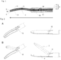
FIG. 1 is a sectional view for illustrating a distal end portion of a medical treatment instrument according to the present invention (the structure in which microwave application antennas are in contact with each other) as seen from above (the direction of the arrow (long-axis direction) corresponds to a distal end side, and the opposite direction corresponds to a terminal end side). -
FIGS. 2 are views for illustrating an opened state and a closed state of both electrodes at the distal end portion of the medical treatment instrument according to the present invention. A: The state in which the electrodes are closed. B:The state in which the electrodes are opened. -
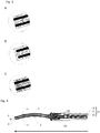
FIGS. 3 are distal end views for illustrating the distal end portion of the medical treatment instrument according to the present invention. A: In both electrodes, a microwave application antenna and a microwave reception antenna are separated from each other. B: In both electrodes, the microwave application antenna and the microwave reception antenna are integrated with each other (connected to each other). C: In both electrodes, the microwave application antenna and the microwave reception antenna are connected to each other through intermediation of a pin. -
FIG. 4 is a sectional view for illustrating a distal end portion of a medical treatment instrument according to another mode of the present invention (the structure in which microwave reception antennas are in contact with each other) as seen from above (the direction of the arrow (long-axis direction) corresponds to the distal end side, and the opposite direction corresponds to the terminal end side). -
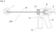
FIG. 5 is an overall view of the medical treatment instrument according to the present invention. - Hereinafter, the present invention is described with reference to the drawings. However, the present invention is not limited to medical treatment illustrated in the drawings.
- A medical treatment instrument (100) according to the present invention relates to a microwave radiation instrument (in particular, microwave radiation surgical instrument) capable of irradiating tissue with a microwave from both electrodes (see
FIG. 1 to FIG. 5 ). - The medical treatment instrument (100) according to the present invention includes distal end portion (1) comprising at least the following components.
- A first electrode (4) including a microwave application antenna 1 (2) and a microwave reception antenna 1 (3).
- A second electrode (7) which is arranged to be opposed to the first electrode (4), and includes a microwave application antenna 2 (5) and a microwave reception antenna 2 (6).
- A coaxial cable (8) including a center conductor (10) and an outer conductor (9). The center conductor (10) is directly or indirectly connected to the microwave application antenna 1 (2) and the microwave application antenna 2 (5), and the outer conductor (9) is directly or indirectly connected to the microwave reception antenna 1 (3) and the microwave reception antenna 2 (6).
- The medical treatment instrument (100) according to the present invention has structure in which the microwave application antenna 1 (2) and the microwave application antenna 2 (5) are in contact with each other under a state in which the first electrode (4) and the second electrode (7) are closed or structure in which the microwave reception antenna 1 (3) and the microwave reception antenna 2 (6) are in contact with each other under the state in which the first electrode (4) and the second electrode (7) are closed (see
FIG. 2A ), and a microwave is allowed to be radiated from both the first electrode (4) and the second electrode (7). - As an example of a method of connecting the microwave reception antenna 1 (3) and the microwave reception antenna 2 (6) to the outer conductor (9), the microwave reception antenna 1 (3) and the microwave reception antenna 2 (6) are connected to the outer conductor (9) through intermediation of a pin (12). With this configuration, both or one of the microwave reception antenna 1 (3) and the microwave reception antenna 2 (6) is movable. Therefore, the first electrode (4) and/or the second electrode (7) is movable.
- As an example of the pin (12) in the present invention, although not particularly limited, the pin (12) may have any shape as long as two or more members can be directly or indirectly coupled to each other, or two or more members are rotatable about the pin (12).
- As an example of a method of connecting the microwave application antenna 1 (2) and the microwave application antenna 2 (5) to the center conductor (10), the center conductor (10) has a distal end having a two-legged fork shape, that is, a shape that is branched into two legs, and the microwave application antenna 1 (2) and the microwave application antenna 2 (5) are directly or indirectly connected to the branched two legs of the center conductor (10), respectively. The microwave application antenna 1 (2) and the microwave application antenna 2 (5) are separated from the microwave reception antenna 1 (3) and the microwave reception antenna 2 (6), respectively, through intermediation of a dielectric (insulator) (11).
- The medical treatment instrument (100) according to the present invention is not particularly limited as long as the medical treatment instrument (100) is movable such that tissue can be gripped in a gap defined between both electrodes which are the first electrode (4) and the second electrode (7), and examples thereof may include forceps and tweezers (see
FIGS. 2 ). As an example of the forceps, any publicly known forceps can be used as the forceps used in the present invention. Examples of the forceps used in the present invention may include Kelly forceps, Kocher forceps, Pean forceps, and Allis forceps. However, the forceps are not particularly limited. - A frequency of microwave to be transmitted to the coaxial cable (8) of the medical treatment instrument (100) according to the present invention is not particularly limited, but is from 300 MHz to 300 GHz (wavelength: from 1 m to 1 mm), preferably from 0.9 GHz to 30 GHz. A transmission method can easily be achieved by any publicly known method, for example, a method of connecting the medical treatment instrument (100) to a publicly known microwave oscillator configured to oscillate a microwave or a method of providing the oscillator in the medical treatment instrument (101).
- Power used in the present invention is from 0.1 W to 200 W, preferably from 1.0 W to 80 W.
- The coaxial cable (8) used in the present invention is formed of, for example, a center conductor, a shield tube, and an earth pipe or a braided copper wire. The center conductor is an electric conductor made of copper. The shield tube is an insulator or a dielectric (which is made of, for example, Teflon (trademark) or polyethylene) configured to cover the center conductor. The earth pipe or the braided copper wire is an outer conductor (electric conductor) made of, for example, copper, stainless steel, or brass.
- The coaxial cable (8) may be a publicly known semi-rigid coaxial cable.
- The microwave application antenna 1 (2) and the microwave application antenna 2 (5) of the present invention are not particularly limited as long as the microwave application antenna 1 (2) and the microwave application antenna 2 (5) are made of a material that enables supply of a microwave. A conductive material, such as silver, copper, gold, iron, titanium, stainless steel, phosphor bronze, or brass, may be widely used. Suitable examples thereof include silver, copper, gold, stainless steel, and brass.
- The microwave reception antenna 1 (3) and the microwave reception antenna 2 (6) of the present invention are not particularly limited as long as the microwave reception antenna 1 (3) and the microwave reception antenna 2 (6) are made of a material that enables reception of a microwave. A conductive material, such as silver, copper, gold, iron, titanium, stainless steel, phosphor bronze, or brass, may be widely used. Suitable examples thereof include silver, copper, gold, stainless steel, and brass.
- A shape of the antenna is not particularly limited. Examples of the shape of the antenna include a circular cone, a triangular pyramid, a quadrangular pyramid, a column, a quadrangular prism, a triangular prism, a sphere, a cube, a cuboid, a tooth shape, a cylindrical shape, a rod shape, and a sawtooth shape. Further, for an inner surface (in particular, contact surface with respect to tissue) of the antenna, shapes such as a planar shape and a protrusion/recess shape are widely applicable.
- As a specific configuration of the microwave application antenna of the present invention, the quadrangular prism may be adopted, and the contact surface with respect to tissue may have the sawtooth shape so that tissue is less liable to slip. As a specific configuration of the microwave reception antenna, the quadrangular prism may be adopted, and the contact surface with respect to tissue may have the sawtooth shape so that tissue is less liable to slip.
- The first electrode (4) of the present invention includes the microwave application antenna 1 (2) and the microwave reception antenna 1 (3). The second electrode (7) of the present invention includes the microwave application antenna 2 (5) and the microwave reception antenna 2 (6).
- Further, the first electrode (4) and the second electrode (7) are not particularly limited as long as the first electrode (4) and the second electrode (7) are movable so as to be capable of gripping tissue in the gap defined between both electrodes (in particular, forceps) and further have a coagulating function and/or a cutting function as needed. Further, any one or both of the first electrode (4) and the second electrode (7) may be a fixed electrode or a movable electrode.
- It is more preferred that the electrodes each be partially or entirely subjected to coating that causes coagulated tissue to be less liable to adhere to the electrodes during contact with the tissue. The coating is performed with, for example, gold or a Teflon-based member. With this, processing of coagulation and cutting can be successively performed without causing adhesion of coagulated tissue. It is preferred that the electrodes of the present invention be formed without use of a ceramic material.
- A configuration of the distal end portions of the first electrode (4) and/or the second electrode (7) of the present invention for efficient radiation of a microwave is described below.
- In both electrodes, the microwave application antenna (2, 5) and the microwave reception antenna (3, 6) are separated from each other (preferably, separated in the range of from the terminal end to the distal end) (see
FIG. 3A ). - In both electrodes, the microwave application antenna (2, 5) and the microwave reception antenna (3, 6) are integrated with each other (connected to each other, preferably, the microwave application antenna (2, 5) and the microwave reception antenna (3, 6) are integrated with each other on the distal end side) (see
FIG. 3B ). - As examples of the integration, the microwave application antenna (2, 5) and the microwave reception antenna (3, 6) may be manufactured as an integrated component, or distal end portions thereof may have a material that does not affect the microwave radiation and is applied through vapor deposition.
- In both electrodes, the microwave application antenna (2, 5) and the microwave reception antenna (3, 6) are connected to each other through intermediation of, for example, the pin (12) (see
FIG. 3C ). - In the first electrode (4), the microwave application antenna 1 (2) and the microwave reception antenna 1 (3) are installed through intermediation of the insulator (dielectric) (11). For example, the insulator (dielectric) (11) has such a shape that allows the insulator (dielectric) (11) to be sandwiched between the microwave application antenna 1 (2) and the microwave reception antenna 1 (3) (see
FIG. 1 ). With this configuration, the microwave application antenna 1 (2) and the microwave reception antenna 1 (3) are partially or entirely insulated. - In the second electrode (7), the microwave application antenna 2 (5) and the microwave reception antenna 2 (6) are installed through intermediation of the insulator (dielectric) (11). More specifically, the insulator (dielectric) (11) has such a shape that allows the insulator (dielectric) (11) to be sandwiched between the microwave application antenna 2 (5) and the microwave reception antenna 2 (6) (see
FIG. 1 ). With this configuration, the microwave application antenna 2 (5) and the microwave reception antenna 2 (6) are partially or entirely insulated. - Examples of the insulator or dielectric may include a PEEK resin, Teflon (trademark), and ceramic.
- A shaft portion (20) of the present invention (see
FIG. 5 ) may have the same structure as that of a shaft portion of a publicly known medical instrument, but it is preferred that the shaft portion (20) include the coaxial cable (8). Further, the shaft portion (20) may include a shaft rotating knob (21). Through rotation of the shaft rotating knob (21), the distal end portion (1) and the shaft portion (20) can be rotated. - A grip portion (30) of the present invention (see
FIG. 5 ) may have the same structure as that of a grip portion of a publicly known medical instrument. The grip portion (30) may include a connector (31), a microwave radiation switch (32), and an electrode moving switch (33). - The connector (31) is connected to the coaxial cable (8) so that rotation of the connector (31) allows the distal end portion (1) and the shaft portion (20) to rotate.
- The microwave radiation switch (32) is capable of not only turning on and off the microwave radiation but also adjusting the intensity of the microwave radiation.
- The electrode moving switch (33) is capable of performing an operation of opening and closing both electrodes.
- The present invention is specifically described below by way of Examples, but the present invention is not limited to Examples.
- (Example 1 of Medical Treatment Instrument according to the Present Invention)
- In Example 1, there is given a medical treatment instrument having the structure in which the microwave application antennas are in contact with each other as illustrated in
FIG. 1 . - Stainless steel is used for each of the antennas, and a PEEK resin is used for the insulator (dielectric) (11). In both electrodes, the microwave application antenna and the microwave reception antenna are separated (see
FIG. 3A ). - It was confirmed that, through coagulation of a liver of a pig with use of the medical treatment instrument of Example 1, the medical treatment instrument of Example 1 was able to suppress sparks and evenly radiate a microwave.
- In Example 2, there is given a medical treatment instrument having the structure in which the microwave reception antennas are in contact with each other as illustrated in
FIG. 4 . - Stainless steel is used for each of the antennas, and a PEEK resin is used for the insulator (dielectric) (11). In both electrodes, the microwave application antenna and the microwave reception antenna are separated (see
FIG. 3A ). - The medical treatment instrument according to the present invention has one or more of the following effects.
- (1) Tissue can be efficiently irradiated with a microwave radiated from both electrodes.
- (2) Sparks can be suppressed without use of the ceramic material for both electrodes.
- (3) A microwave can be substantially evenly radiated from surfaces of the microwave application antennas.
- According to the present invention, a medical treatment instrument capable of efficiently irradiating tissue with a microwave radiated from both electrodes can be provided.
-
- 100: medical treatment instrument
- 1: distal end portion
- 2: microwave application antenna 1
- 3: microwave reception antenna 1
- 4: first electrode (fixed electrode)
- 5:
microwave application antenna 2 - 6:
microwave reception antenna 2 - 7: second electrode (movable electrode)
- 8: coaxial cable
- 9: outer conductor
- 10: center conductor
- 11: dielectric (insulator)
- 12: pin
- 20: shaft portion
- 21: shaft rotating knob
- 30: grip portion
- 31: connector
- 32: microwave radiation switch
- 33: electrode moving switch
- 50: mating surfaces of upper and lower blades
- 51: connection portion between outer conductor of coaxial cable and outer conductor of electrode
- 52: connection portion between center conductor of coaxial cable and center conductor of electrode
- 53: portion at which antennas are internally in contact with each other and at which center conductor is branched
Claims (12)
- A medical treatment instrument comprising a distal end portion,
the distal end portion including:a first electrode including a microwave application antenna 1 and a microwave reception antenna 1;a second electrode which is arranged to be opposed to the first electrode, and includes a microwave application antenna 2 and a microwave reception antenna 2; anda coaxial cable including a center conductor and an outer conductor, the center conductor being directly or indirectly connected to the microwave application antenna 1 and the microwave application antenna 2, the outer conductor being directly or indirectly connected to the microwave reception antenna 1 and the microwave reception antenna 2,wherein the medical treatment instrument has structure in which the microwave application antenna 1 and the microwave application antenna 2 are in contact with each other under a state in which the first electrode and the second electrode are closed or structure in which the microwave reception antenna 1 and the microwave reception antenna 2 are in contact with each other under the state in which the first electrode and the second electrode are closed, and
wherein a microwave is allowed to be radiated from both the first electrode and the second electrode. - The medical treatment instrument according to claim 1, wherein the center conductor has a distal end having a shape that is branched into two legs, and the microwave application antenna 1 and the microwave application antenna 2 are directly or indirectly connected to the branched two legs of the center conductor.
- The medical treatment instrument according to claim 1, wherein the microwave application antenna 1 and the microwave application antenna 2 are connected to the outer conductor through intermediation of a pin.
- The medical treatment instrument according to any one of claims 1 to 3, wherein, in the first electrode, the microwave application antenna 1 and the microwave reception antenna 1 are installed through intermediation of an insulator or a dielectric, and in the second electrode, the microwave application antenna 2 and the microwave reception antenna 2 are installed through intermediation of an insulator or a dielectric.
- The medical treatment instrument according to any one of claims 1 to 4, wherein a distal end of the microwave application antenna 1 and a distal end of the microwave reception antenna 1 are connected to each other, and/or a distal end of the microwave application antenna 2 and a distal end of the microwave reception antenna 2 are connected to each other.
- The medical treatment instrument according to any one of claims 1 to 4, wherein a distal end of the microwave application antenna 1 and a distal end of the microwave reception antenna 1 are connected to each other through intermediation of a pin, and/or a distal end of the microwave application antenna 2 and a distal end of the microwave reception antenna 2 are connected to each other through intermediation of a pin.
- The medical treatment instrument according to any one of claims 1 to 6, wherein the first electrode is a fixed electrode, and the second electrode is a movable electrode.
- The medical treatment instrument according to any one of claims 1 to 7, further comprising:a shaft portion including the coaxial cable; anda grip portion including a connector to which the coaxial cable is connected,wherein rotation of the connector allows the distal end portion and the shaft portion to rotate.
- The medical treatment instrument according to claim 8, further comprising a shaft rotating knob installed on the shaft portion.
- The medical treatment instrument according to any one of claims 1 to 9, wherein the first electrode and the second electrode are formed without use of ceramic.
- A medical treatment instrument comprising a distal end portion,
the distal end portion including:a first electrode including a microwave application antenna 1 and a microwave reception antenna 1;a second electrode which is arranged to be opposed to the first electrode, and includes a microwave application antenna 2 and a microwave reception antenna 2; anda coaxial cable including a center conductor and an outer conductor, the center conductor being directly or indirectly connected to the microwave application antenna 1 and the microwave application antenna 2, the outer conductor being directly or indirectly connected to the microwave reception antenna 1 and the microwave reception antenna 2,wherein, in the first electrode, the microwave application antenna 1 and the microwave reception antenna 1 are installed through intermediation of an insulator or a dielectric, and in the second electrode, the microwave application antenna 2 and the microwave reception antenna 2 are installed through intermediation of an insulator or a dielectric,
wherein the medical treatment instrument has structure in which the microwave application antenna 1 and the microwave application antenna 2 are in contact with each other under a state in which the first electrode and the second electrode are closed, and
wherein a microwave is allowed to be radiated from both the first electrode and the second electrode. - The medical treatment instrument according to claim 11, wherein the first electrode and the second electrode are formed without use of ceramic.
Applications Claiming Priority (2)
| Application Number | Priority Date | Filing Date | Title |
|---|---|---|---|
| JP2018147403 | 2018-08-06 | ||
| PCT/JP2019/030807 WO2020031994A1 (en) | 2018-08-06 | 2019-08-06 | Medical treatment instrument |
Publications (2)
| Publication Number | Publication Date |
|---|---|
| EP3834761A1 true EP3834761A1 (en) | 2021-06-16 |
| EP3834761A4 EP3834761A4 (en) | 2021-11-03 |
Family
ID=69414837
Family Applications (1)
| Application Number | Title | Priority Date | Filing Date |
|---|---|---|---|
| EP19847768.9A Pending EP3834761A4 (en) | 2018-08-06 | 2019-08-06 | Medical treatment instrument |
Country Status (3)
| Country | Link |
|---|---|
| EP (1) | EP3834761A4 (en) |
| JP (1) | JP6784433B2 (en) |
| WO (1) | WO2020031994A1 (en) |
Families Citing this family (1)
| Publication number | Priority date | Publication date | Assignee | Title |
|---|---|---|---|---|
| JP7325068B2 (en) * | 2021-03-04 | 2023-08-14 | 日機装株式会社 | medical instrument |
Family Cites Families (10)
| Publication number | Priority date | Publication date | Assignee | Title |
|---|---|---|---|---|
| JP3464383B2 (en) | 1998-05-20 | 2003-11-10 | 三菱電機株式会社 | Power distribution circuit and power amplifier |
| JP4701401B2 (en) * | 2006-08-31 | 2011-06-15 | 国立大学法人滋賀医科大学 | Microwave surgical device |
| US7998139B2 (en) * | 2007-04-25 | 2011-08-16 | Vivant Medical, Inc. | Cooled helical antenna for microwave ablation |
| US20100249769A1 (en) * | 2009-03-24 | 2010-09-30 | Tyco Healthcare Group Lp | Apparatus for Tissue Sealing |
| EP2520243B1 (en) * | 2009-12-28 | 2015-03-25 | National University Corporation Shiga University OF Medical Science | Medical treatment device |
| JP5514089B2 (en) | 2010-11-30 | 2014-06-04 | 株式会社 オリエントマイクロウェーブ | Microwave surgical device |
| EP2742893B1 (en) * | 2011-08-10 | 2016-10-19 | National University Corporation Shiga University OF Medical Science | Microwave surgical instrument |
| GB201317713D0 (en) | 2013-10-07 | 2013-11-20 | Creo Medical Ltd | Electrosurgical device |
| GB2550375B (en) * | 2016-05-17 | 2021-12-01 | Creo Medical Ltd | Electrosurgical cutting tool |
| JP2018147403A (en) | 2017-03-08 | 2018-09-20 | 東芝テック株式会社 | Sales data processing device and program |
-
2019
- 2019-08-06 WO PCT/JP2019/030807 patent/WO2020031994A1/en unknown
- 2019-08-06 EP EP19847768.9A patent/EP3834761A4/en active Pending
- 2019-08-06 JP JP2020501412A patent/JP6784433B2/en active Active
Also Published As
| Publication number | Publication date |
|---|---|
| JPWO2020031994A1 (en) | 2020-08-20 |
| EP3834761A4 (en) | 2021-11-03 |
| WO2020031994A1 (en) | 2020-02-13 |
| JP6784433B2 (en) | 2020-11-11 |
Similar Documents
| Publication | Publication Date | Title |
|---|---|---|
| US10932854B2 (en) | Electrosurgical forceps for delivering RF and/or microwave energy into biological tissue | |
| EP2641559B1 (en) | Apparatus for tissue sealing | |
| US9131985B2 (en) | Medical treatment device | |
| EP2742893B1 (en) | Microwave surgical instrument | |
| CN108633251B (en) | Biopsy forceps tool | |
| CN109303607B (en) | Electrosurgical forceps for delivering microwave energy from a non-resonant unbalanced lossy transmission line structure | |
| EP2520243B1 (en) | Medical treatment device | |
| EP3834761A1 (en) | Medical treatment instrument | |
| JP2011135988A (en) | Medical treatment instrument | |
| US20220409229A1 (en) | Medical treatment tool and electromagnetic wave medical system | |
| WO2018147243A1 (en) | Medical treatment tool | |
| WO2023140373A1 (en) | Medical treatment tool |
Legal Events
| Date | Code | Title | Description |
|---|---|---|---|
| STAA | Information on the status of an ep patent application or granted ep patent |
Free format text: STATUS: THE INTERNATIONAL PUBLICATION HAS BEEN MADE |
|
| PUAI | Public reference made under article 153(3) epc to a published international application that has entered the european phase |
Free format text: ORIGINAL CODE: 0009012 |
|
| STAA | Information on the status of an ep patent application or granted ep patent |
Free format text: STATUS: REQUEST FOR EXAMINATION WAS MADE |
|
| 17P | Request for examination filed |
Effective date: 20210304 |
|
| AK | Designated contracting states |
Kind code of ref document: A1 Designated state(s): AL AT BE BG CH CY CZ DE DK EE ES FI FR GB GR HR HU IE IS IT LI LT LU LV MC MK MT NL NO PL PT RO RS SE SI SK SM TR |
|
| A4 | Supplementary search report drawn up and despatched |
Effective date: 20211005 |
|
| RIC1 | Information provided on ipc code assigned before grant |
Ipc: A61B 18/18 20060101AFI20210929BHEP |
|
| DAV | Request for validation of the european patent (deleted) | ||
| DAX | Request for extension of the european patent (deleted) | ||
| STAA | Information on the status of an ep patent application or granted ep patent |
Free format text: STATUS: EXAMINATION IS IN PROGRESS |
|
| 17Q | First examination report despatched |
Effective date: 20240119 |