WO2020031886A1 - 乗物の窓ガラス用の合わせガラス - Google Patents
乗物の窓ガラス用の合わせガラス Download PDFInfo
- Publication number
- WO2020031886A1 WO2020031886A1 PCT/JP2019/030464 JP2019030464W WO2020031886A1 WO 2020031886 A1 WO2020031886 A1 WO 2020031886A1 JP 2019030464 W JP2019030464 W JP 2019030464W WO 2020031886 A1 WO2020031886 A1 WO 2020031886A1
- Authority
- WO
- WIPO (PCT)
- Prior art keywords
- glass plate
- antenna
- layer
- disposed
- laminated glass
- Prior art date
- Legal status (The legal status is an assumption and is not a legal conclusion. Google has not performed a legal analysis and makes no representation as to the accuracy of the status listed.)
- Ceased
Links
Images


Classifications
-
- B—PERFORMING OPERATIONS; TRANSPORTING
- B60—VEHICLES IN GENERAL
- B60J—WINDOWS, WINDSCREENS, NON-FIXED ROOFS, DOORS, OR SIMILAR DEVICES FOR VEHICLES; REMOVABLE EXTERNAL PROTECTIVE COVERINGS SPECIALLY ADAPTED FOR VEHICLES
- B60J1/00—Windows; Windscreens; Accessories therefor
-
- B—PERFORMING OPERATIONS; TRANSPORTING
- B60—VEHICLES IN GENERAL
- B60S—SERVICING, CLEANING, REPAIRING, SUPPORTING, LIFTING, OR MANOEUVRING OF VEHICLES, NOT OTHERWISE PROVIDED FOR
- B60S1/00—Cleaning of vehicles
- B60S1/02—Cleaning windscreens, windows or optical devices
-
- H—ELECTRICITY
- H01—ELECTRIC ELEMENTS
- H01Q—ANTENNAS, i.e. RADIO AERIALS
- H01Q1/00—Details of, or arrangements associated with, antennas
- H01Q1/12—Supports; Mounting means
- H01Q1/22—Supports; Mounting means by structural association with other equipment or articles
-
- H—ELECTRICITY
- H01—ELECTRIC ELEMENTS
- H01Q—ANTENNAS, i.e. RADIO AERIALS
- H01Q1/00—Details of, or arrangements associated with, antennas
- H01Q1/27—Adaptation for use in or on movable bodies
- H01Q1/32—Adaptation for use in or on road or rail vehicles
-
- H—ELECTRICITY
- H05—ELECTRIC TECHNIQUES NOT OTHERWISE PROVIDED FOR
- H05B—ELECTRIC HEATING; ELECTRIC LIGHT SOURCES NOT OTHERWISE PROVIDED FOR; CIRCUIT ARRANGEMENTS FOR ELECTRIC LIGHT SOURCES, IN GENERAL
- H05B3/00—Ohmic-resistance heating
- H05B3/84—Heating arrangements specially adapted for transparent or reflecting areas, e.g. for demisting or de-icing windows, mirrors or vehicle windshields
Definitions
- the present disclosure relates to a laminated glass having an antenna, which is used for a window glass of a vehicle such as a vehicle.
- Patent Document 1 describes that laminated glass having an antenna and a heating wire is used for a windshield and a rear glass of a vehicle.
- the laminated glass has two glass plates and an adhesive intermediate layer disposed between the two glass plates. Further, a heating layer made of a resin film to which a heating wire is attached is arranged at the center in the thickness direction of the intermediate layer, and the antenna is arranged on the outer surface of one of the glass plates or in the intermediate layer. The antenna is disposed in a region where the heating wire is not provided when viewed from the normal direction of the laminated glass.
- the antenna is coupled to the feeding portion by non-contact coupling such as capacitive coupling, and it is desired that this coupling be strengthened.
- the present invention relates to a laminated glass for a window glass of a vehicle in which an antenna layer having a resin film is disposed between an inner glass plate and an outer glass plate.
- the purpose is to strengthen non-contact type bonding.
- a laminated glass according to at least some embodiments of the present invention is a laminated glass (1) for a window glass of a vehicle, wherein an inner glass plate (2) disposed inside and an outer glass disposed outside.
- a plate (3) an antenna layer disposed between the inner glass plate and the outer glass plate and having a first film (10) made of resin and an antenna wire (11) attached to the first film; (4), an adhesive first intermediate layer (6) disposed between the inner glass plate and the antenna layer, and an adhesive second intermediate layer disposed between the antenna layer and the outer glass plate ( 7), and a feeder (9) disposed inside the inner glass plate and connected to the antenna line so as to be able to transmit a signal.
- the middle between the serial outer glass sheet characterized in that arranged closer to the side of the inner glass plate.
- the laminated glass according to at least some embodiments of the present invention is characterized in that, in the above-described configuration, the antenna wire is capacitively coupled to the power feeding unit.
- connection between the antenna line and the power supply unit that can transmit a signal is facilitated.
- the laminated glass according to at least some embodiments of the present invention is disposed between the antenna layer and the second intermediate layer, and includes a second film (12) made of resin and the second film (12).
- the second intermediate layer is compared with a case where the heat generation layer is disposed at the center between the inner glass plate and the outer glass plate. Is relatively thin and the rigidity of the outer glass plate suppresses the distortion.
- the heat generating layer is disposed closer to the outer glass plate, it is advantageous to dissolve frost adhering to the outer surface of the laminated glass.
- the first intermediate layer is thinner than when the antenna layer is disposed at the center between the inner glass plate and the outer glass plate. In addition, the distortion is suppressed by the rigidity of the inner glass plate.
- the antenna wire and the heating wire are orthogonal to each other. It is characterized by being arranged in a straight line.
- a radio wave having a polarization orthogonal to the heating wire is not interfered by the heating wire, and can be efficiently transmitted and received by the antenna wire orthogonal to the heating wire.
- the antenna wire in the above-described configuration, in the at least some regions, extends in a horizontal direction, and the heating wire extends in a vertical direction.
- lateral direction means a horizontal direction along the surface of the laminated glass
- longitudinal direction means a direction orthogonal to the horizontal direction along the surface of the laminated glass.
- the antenna wire can transmit and / or receive the horizontally polarized wave without interference with the heating wire.
- the laminated glass according to at least some embodiments of the present invention is characterized in that, in the above-described configuration, the antenna wire transmits and receives a digital terrestrial television broadcast signal.
- a horizontally polarized terrestrial digital television broadcast signal can be transmitted and received without interference with the heating wire.
- the non-contact type coupling to the feeding portion of the antenna can be strengthened.
- the laminated glass 1 according to the first embodiment is disposed between an inner glass plate 2 disposed on the vehicle interior side, an outer glass plate 3 disposed on the vehicle exterior side, and the inner glass plate 2 and the outer glass plate 3.
- a heating layer 5 disposed between the inner glass plate 2 and the outer glass plate 3 and a first intermediate layer disposed between the inner glass plate 2 and the antenna layer 4 so that the inner glass plate 2 and the antenna layer 4 are bonded to each other.
- a third intermediate layer 8, and a power supply unit 9 disposed inside the inner glass plate 2.
- the laminated glass 1 used for the windshield of the automobile is gently curved so that the outer surface is expanded.
- the inner surface of the inner glass plate 2 and the outer surface of the outer glass plate 3 form the inner surface and the outer surface of the laminated glass 1, respectively.
- the distance between the outer surface of the inner glass plate 2 and the inner surface of the outer glass plate 3 may be constant, but may change, for example, so as to become smaller or larger as going upward.
- the antenna layer 4 has a first film 10 and an antenna wire 11 attached to the first film 10.
- the first film 10 is a base material that supports the antenna wire 11 and is made of a resin that transmits visible light.
- the resin constituting the first film 10 for example, polyethylene terephthalate, polyethylene, polymethyl methacrylate, polyvinyl chloride, polyester, polyolefin, polycarbonate, polystyrene, polypropylene, nylon and the like can be used.
- the antenna wire 11 is made of a conductive material. For example, metal such as copper, aluminum, tungsten, and silver can be used as the antenna wire 11.
- the antenna layer 4 is disposed closer to the inner glass plate 2 than the center between the inner glass plate 2 and the outer glass plate 3.
- the heating layer 5 has the second film 12 and the heating wire 13 attached to the second film 12.
- the second film 12 is a base material that supports the heating wires 13 and is made of a resin that transmits visible light, similar to the first film 10.
- the heating wire 13 is made of the same conductive material as the antenna wire 11.
- the heat generating layer 5 is disposed closer to the outer glass plate 3 than the center between the inner glass plate 2 and the outer glass plate 3.
- the antenna wire 11 and the heating wire 13 are arranged so as to be orthogonal to each other in a partial area.
- the antenna wire 11 extends in the horizontal direction so as to transmit and receive a horizontally polarized terrestrial digital television broadcast signal
- the heating wire 13 extends in the vertical direction (coupling) so as not to interfere with the reception of the horizontally polarized wave by the antenna wire 11.
- the antenna wire 11 and the heating wire 13 may be arranged on the whole of the laminated glass 1 or may be partially arranged.
- the antenna wire 11 and the heating wire 13 may have a shape in which a plurality of wires extending linearly in parallel with each other may be connected to each other at both ends, and one wire may be folded at both ends of the arrangement region.
- the shape other than the folded portion may be linearly arranged in parallel with each other.
- the antenna layer 4 and the heat generating layer 5 may have the same horizontal and vertical dimensions as the inner glass plate 2 and the outer glass plate 3, respectively, as in the first embodiment shown in FIG. As in the second embodiment shown in FIG. 1, the inner glass plate 2 and the outer glass plate 3 may have smaller horizontal and vertical dimensions. Further, the surfaces of the antenna layer 4 and the heating layer 5 to which the antenna wires 11 or the heating wires 13 are attached may face the outer glass plate 3 side, respectively, as in the first embodiment shown in FIG. As in the third embodiment shown in FIG. 3, the inner glass plate 2 may face the inner glass plate 2 side.
- the antenna layer 4 and the heat generating layer 5 can be formed by etching, printing, transfer, and the like, respectively.
- the formation of the antenna layer 4 and the heat generation layer 5 by etching is suitable for making the antenna wire 11 and the heating wire 13 thin in order to make it difficult for a driver or the like to see the antenna wire 11 and the heating wire 13.
- a metal thin film serving as a material of the antenna wire 11 is attached to the first film 10 by, for example, sticking, plating, sputtering, CVD, PVD, vacuum deposition, ion plating, or the like.
- a resist layer is provided on the metal thin film, and a pattern is transferred to the resist layer by photolithography or the like.
- the metal thin film in the portion not covered with the resist layer is removed by etching.
- the case where the heating layer 5 is formed by etching is the same as the case of the antenna layer 4.
- the first to third intermediate layers 6, 7, 8 are each made of an adhesive resin that transmits visible light.
- the first to third intermediate layers 6, 7, and 8 polyvinyl butyral and ethylene vinyl acetate can be used.
- the first and second intermediate layers 6 and 7 are preferably thinner than the third intermediate layer 8.
- the thickness of the first and second intermediate layers 6 and 7 is 1 to 400 ⁇ m, preferably 1 to 200 ⁇ m, and more preferably 1 to 50 ⁇ m.
- the thickness of the third intermediate layer 8 is preferably from 600 to 2000 ⁇ m so that it can be easily thinned by extension. Note that the distance between the outer surface of the inner glass plate 2 and the inner surface of the outer glass plate 3 changes so as to become smaller or larger as going upward, and the first to third intermediate layers 6, 7,. When 8 is wedge-shaped in cross section, the above numerical value indicates the thickness of the thickest part.
- the power feeding unit 9 is disposed on the inner surface of the inner glass plate 2 and is electrostatically or electromagnetically connected to the antenna line 11 by capacitive coupling or the like.
- the antenna line 11 capacitively coupled to the feeding unit 9 transmits and / or receives a signal in a frequency band of 100 MHz or more.
- the power supply unit 9 and the antenna line 11 may be connected to each other so that signals can be transmitted to each other, instead of being capacitively coupled.
- the power supply unit 9 may be coupled to the antenna wire 11 by a conductive wire.
- the power supply unit 9 may be arranged between the inner glass plate 2 and the outer glass plate 3.
- a laminate is formed by laminating the inner glass plate 2, the first intermediate layer 6, the antenna layer 4, the third intermediate layer 8, the heat generating layer 5, the second intermediate layer 7, and the outer glass plate 3 in this order.
- the laminate is preliminarily bonded. Preliminary bonding is performed, for example, by placing the laminate in a rubber bag and heating to about 70 to 110 ° C. while suctioning under reduced pressure. The preliminary bonding is performed by heating the laminate to 45 to 65 ° C. using an oven, pressing the laminate at 0.45 to 0.55 MPa with a roll, heating the laminate to 80 to 105 ° C. with an oven, and then heating the laminate to 0.45 to 65 ° C.
- the preliminarily bonded laminate is fully bonded.
- the actual bonding is performed, for example, by heating the pre-bonded laminate to 100 to 150 ° C. at a pressure of 8 to 15 atm by an autoclave.
- the inner glass plate 2 and the antenna layer 4 are bonded to each other by the first intermediate layer 6, and the antenna layer 4 and the heat generating layer 5 are bonded to each other by the third intermediate layer 8.
- the heat generating layer 5 and the outer glass plate 3 are bonded to each other by the second intermediate layer.
- the laminated glass 1 is completed by arranging the feeder 9 on the inner surface of the inner glass plate 2 so as to be capacitively coupled to the antenna line 11.
- the inner glass plate 2 and the outer glass plate 3 have higher rigidity than the first to third intermediate layers 6, 7, 8 which are adhesive resins. Further, the thickness of the second intermediate layer 7 is smaller than when the heat generating layer 5 is disposed at the center between the inner glass plate 2 and the outer glass plate 3.
- the heating wire 13 When the heating wire 13 is energized and generates heat, the heat acts to distort the heat generating layer 5, but the heat generating layer 5 is formed of an outer glass plate having higher rigidity than the first to third intermediate layers 6, 7, and 8. Since the second intermediate layer 7 that is disposed closer to the side 3 and is present between the outer glass plate 3 and the outer glass plate 3 is relatively thin, distortion is suppressed.
- the thickness of the first intermediate layer 6 is smaller than when the antenna layer 4 is arranged at the center between the inner glass plate 2 and the outer glass plate 3.
- the force of distorting the antenna layer 4 acts by the heat of the heating wire.
- the antenna layer 4 is disposed closer to the side of the inner glass plate 2 having higher rigidity than the first to third intermediate layers 6, 7, and 8, and the first intermediate layer existing between the inner glass plate 2 and the first intermediate layer. Since 6 is relatively thin, distortion is suppressed.
- the distortion of the antenna layer 4 and the heat generating layer 5 reduces the clarity of the image of the object seen by the driver of the automobile when the driver or the like looks through the laminated glass 1 outside the vehicle compartment, but the distortion is suppressed. Therefore, even if the object is seen through the laminated glass 1, the object can be clearly seen.
- the antenna line 11 transmits and / or receives signals of media such as digital television, AM radio, FM radio, digital radio (DAB), mobile phone, ITS, and GPS. Since the antenna wire 11 is orthogonal to the heating wire 13 when viewed from the normal direction of the laminated glass 1, the antenna wire 11 efficiently transmits radio waves having a polarization orthogonal to the heating wire 13 without interfering with the heating wire 13. Transmission and / or reception can be performed, and the degree of freedom of the layout of the antenna line 11 is increased.
- media such as digital television, AM radio, FM radio, digital radio (DAB), mobile phone, ITS, and GPS. Since the antenna wire 11 is orthogonal to the heating wire 13 when viewed from the normal direction of the laminated glass 1, the antenna wire 11 efficiently transmits radio waves having a polarization orthogonal to the heating wire 13 without interfering with the heating wire 13. Transmission and / or reception can be performed, and the degree of freedom of the layout of the antenna line 11 is increased.
- the heating wire 13 generates heat when energized, breaks down frost adhering to the outer surface of the laminated glass 1, and prevents and removes fogging and dew condensation generated on the inner surface of the laminated glass 1.
- the power supply unit 9 is disposed on the inner surface of the inner glass plate 2 and capacitively coupled to the antenna line 11, the power supply unit 9 is manufactured as compared with the case where the power supply unit 9 is disposed between the inner glass plate 2 and the outer glass plate 3. Is easy. In addition, since the antenna layer 4 is disposed closer to the inner glass plate 2 than the center between the inner glass plate 2 and the outer glass plate 3, the capacitive coupling becomes strong.
- the heating layer may not be provided.
- the first intermediate layer bonds the inner glass plate and the antenna layer to each other
- the second intermediate layer bonds the antenna layer and the outer glass plate to each other.
- the laminated glass according to the present invention may be applied to a rear glass or a side glass of an automobile, or may be applied to a vehicle other than an automobile, for example, a window glass of a railway vehicle, a ship or an aircraft.
- Laminated glass 2 Inner glass plate 3: Outer glass plate 4: Antenna layer 5: Heat generation layer 6: First intermediate layer 7: Second intermediate layer 8: Third intermediate layer 9: Power supply unit 10: First film 11 : Antenna wire 12: second film 13: heating wire
Landscapes
- Engineering & Computer Science (AREA)
- Mechanical Engineering (AREA)
- Joining Of Glass To Other Materials (AREA)
- Details Of Aerials (AREA)
- Surface Heating Bodies (AREA)
- Support Of Aerials (AREA)
Abstract
【課題】アンテナ層がインナーガラス板とアウターガラス板との間に配置された乗物の窓ガラス用の合わせガラスにおいて、アンテナと給電部との結合を強固にする。 【解決手段】合わせガラス(1)は、内側に配置されたインナーガラス板(2)と、外側に配置されたアウターガラス板(3)と、インナーガラス板及びアウターガラス板間に配置されたアンテナ層(4)と、インナーガラス板及びアンテナ層間に配置された接着性の第1中間層(6)と、アンテナ層及びアウターガラス板間に配置された接着性の第2中間層(7)と、インナーガラス板の内側に配置された給電部(9)とを有する。アンテナ層は、インナーガラス板とアウターガラス板との間の中央よりもインナーガラス板の側に寄って配置される。
Description
本開示は、車両等の乗物の窓ガラスに使用され、アンテナを有する合わせガラスに関する。
特許文献1には、アンテナ及び加熱線を有する合わせガラスを車両のフロントガラスやリアガラスに使用することが記載されている。この合わせガラスは、2枚のガラス板と、両者の間に配置された接着性の中間層とを有する。また、加熱線を被着させた樹脂製のフィルムからなる発熱層が中間層の厚さ方向の中央に配置され、アンテナが一方のガラス板の外表面又は中間層内に配置されている。アンテナは、合わせガラスの法線方向から見て、加熱線が設けられていない領域に配置される。
アンテナが中間層に配置された合わせガラスでは、容量結合等の非接触型の結合によってアンテナが給電部に結合されるが、この結合を強固にすることが望まれている。
このような問題を鑑み、本発明は、樹脂製のフィルムを有するアンテナ層がインナーガラス板とアウターガラス板との間に配置された乗物の窓ガラス用の合わせガラスにおいて、アンテナの給電部への非接触型の結合を強固にすることを目的とする。
本発明の少なくともいくつかの実施形態に係る合わせガラスは、乗物の窓ガラス用の合わせガラス(1)であって、内側に配置されたインナーガラス板(2)と、外側に配置されたアウターガラス板(3)と、前記インナーガラス板及び前記アウターガラス板間に配置され、樹脂を素材とする第1フィルム(10)及び前記第1フィルムに被着されたアンテナ線(11)を有するアンテナ層(4)と、前記インナーガラス板及び前記アンテナ層間に配置された接着性の第1中間層(6)と、前記アンテナ層及び前記アウターガラス板間に配置された接着性の第2中間層(7)と、前記インナーガラス板よりも内側に配置され、信号を伝達可能に前記アンテナ線に接続した給電部(9)とを有し、前記アンテナ層は、前記インナーガラス板と前記アウターガラス板との間の中央よりも前記インナーガラス板の側に寄って配置されたことを特徴とする。
この構成によれば、給電部からアンテナ線までの距離が短くなるため、アンテナの給電部への非接触型の結合が強固になる。
本発明の少なくともいくつかの実施形態に係る合わせガラスは、上記構成において、前記アンテナ線は、前記給電部に容量結合されていることを特徴とする。
この構成によれば、アンテナ線及び給電部間の信号伝達可能な接続が容易になる。
本発明の少なくともいくつかの実施形態に係る合わせガラスは、上記構成の何れかにおいて、前記アンテナ層及び前記第2中間層間に配置され、樹脂を素材とする第2フィルム(12)及び前記第2フィルムに被着された加熱線(13)を有する発熱層(5)と、前記アンテナ層及び前記発熱層間に配置された接着性の第3中間層(8)とを更に有し、前記発熱層は、前記インナーガラス板と前記アウターガラス板との間の中央よりも前記アウターガラス板の側に寄って配置されたことを特徴とする。
この構成によれば、加熱線の発熱等によって発熱層をゆがませる力が働いても、発熱層をインナーガラス板とアウターガラス板との間の中央に配置した場合に比べて第2中間層が比較的薄いことや、アウターガラス板の剛性によってそのゆがみが抑制される。また、発熱層がアウターガラス板に寄って配置されるため、合わせガラスの外表面に付着した霜を解かすのに有利である。また、加熱線の熱を受けてアンテナ層をゆがませる力が働いても、アンテナ層をインナーガラス板とアウターガラス板との間の中央に配置した場合に比べて第1中間層が薄いことや、インナーガラス板の剛性によってそのゆがみが抑制される。
本発明の少なくともいくつかの実施形態に係る合わせガラスは、上記構成において、当該合わせガラスの法線方向から見た少なくとも一部の領域において、前記アンテナ線及び前記加熱線は、互いに直交するように直線状に配置されたことを特徴とする。
この構成によれば、加熱線に直交する向きの偏波をもつ電波は、加熱線に干渉されないため、加熱線に直交するアンテナ線により効率よく送受信できる。
本発明の少なくともいくつかの実施形態に係る合わせガラスは、上記構成において、前記少なくとも一部の領域において、前記アンテナ線は横方向に延在し、前記加熱線は縦方向に延在することを特徴とする。ここで、「横方向」とは合わせガラスの表面に沿った水平方向を意味し、「縦方向」とは合わせガラスの表面に沿って横方向に直交する方向を意味する。
この構成によれば、アンテナ線は水平偏波を加熱線に干渉されずに送信及び/又は受信することができる。
本発明の少なくともいくつかの実施形態に係る合わせガラスは、上記構成において、前記アンテナ線は、地上デジタルテレビ放送の信号を送受信することを特徴とする。
この構成によれば、水平偏波の地上デジタルテレビ放送の信号を加熱線に干渉されずに送受信することができる。
本発明によれば、アンテナ層を有する合わせガラスにおいて、アンテナの給電部への非接触型の結合を強固にできる。
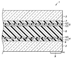
以下、図面を参照して本発明を自動車のフロントガラスに適用した実施形態について説明する。図1~図3は、それぞれ、第1~第3実施形態に係る合わせガラス1の横方向(合わせガラス1の表面に沿った水平方向)に直交する断面における模式的な断面図である。
第1実施形態に係る合わせガラス1は、車室内側に配置されたインナーガラス板2と、車室外側に配置されたアウターガラス板3と、インナーガラス板2及びアウターガラス板3間に配置されたアンテナ層4と、インナーガラス板2及びアウターガラス板3間に配置された発熱層5と、インナーガラス板2及びアンテナ層4を互いに接着するように両者の間に配置された第1中間層6と、発熱層5及びアウターガラス板3を互いに接着するように両者の間に配置された第2中間層7と、アンテナ層4及び発熱層5を互いに接着するように両者の間に配置された第3中間層8と、インナーガラス板2よりも内側に配置された給電部9とを有する。
自動車のフロントガラスに使用される合わせガラス1は、外表面が膨らむように緩やかに湾曲している。インナーガラス板2の内側の表面及びアウターガラス板3の外側の表面が、それぞれ合わせガラス1の内表面及び外表面を形成する。インナーガラス板2の外側の表面とアウターガラス板3の内側の表面との間の距離は、一定でもよいが、例えば、上方に向かうに従って小さく又は大きくなるように変化していてもよい。
アンテナ層4は、第1フィルム10と、第1フィルム10に被着されたアンテナ線11とを有する。第1フィルム10は、アンテナ線11を支持する基材であり、可視光を透過する樹脂を素材とする。第1フィルム10を構成する樹脂として、例えば、ポリエチレンテレフタレート、ポリエチレン、ポリメチルメタクリレート、ポリ塩化ビニル、ポリエステル、ポリオレフィン、ポリカーボネート、ポリスチレン、ポリプロピレン、ナイロン等を使用できる。アンテナ線11は、導電性物質を素材とする。例えば、アンテナ線11として、銅やアルミニウム、タングステン、銀等の金属を使用できる。アンテナ層4は、インナーガラス板2とアウターガラス板3との間の中央よりもインナーガラス板2の側に寄って配置される。
発熱層5は、第2フィルム12と、第2フィルム12に被着された加熱線13とを有する。第2フィルム12は、加熱線13を支持する基材であり、第1フィルム10と同様の可視光を透過する樹脂を素材とする。加熱線13は、アンテナ線11と同様の導電性物質を素材とする。発熱層5は、インナーガラス板2とアウターガラス板3との間の中央よりもアウターガラス板3の側に寄って配置される。
合わせガラス1の法線方向から見て、一部の領域でアンテナ線11と加熱線13とは互いに直交するように重なって配置される。例えば、アンテナ線11が水平偏波の地上デジタルテレビ放送の信号を送受信するように横方向に延在し、加熱線13はアンテナ線11による水平偏波の受信に干渉しないように縦方向(合わせガラス1の表面に沿い、かつ横方向に直交する方向)に延在する。アンテナ線11及び加熱線13は、合わせガラス1の全体に配置されてもよく、部分的に配置されてもよい。合わせガラス1の法線方向から見て、アンテナ線11のみが配置される領域や、加熱線13のみが配置される領域があってもよい。例えば、アンテナ線11及び加熱線13は、互いに平行に直線状に延在する複数の線が両端部で互いに連結した形状であってもよく、1本の線が配置領域の両端部で折り返され、折り返し部以外の部分が互いに平行に直線状に配置された形状であってもよい。
アンテナ層4及び発熱層5は、それぞれ、図1に示す第1実施形態のように、インナーガラス板2及びアウターガラス板3と同じ横方向寸法及び縦方向寸法を有してもよく、図2に示す第2実施形態のように、インナーガラス板2及びアウターガラス板3よりも小さい横方向寸法及び縦方向寸法を有してもよい。また、アンテナ層4及び発熱層5におけるアンテナ線11又は加熱線13が被着した表面が、それぞれ、図1に示す第1実施形態のように、アウターガラス板3側を向いていてもよく、図3に示す第3実施形態のように、インナーガラス板2側を向いていてもよい。
アンテナ層4及び発熱層5は、それぞれ、エッチングや、印刷、転写等により作成することができる。エッチングによるアンテナ層4及び発熱層5の作成は、運転者等からアンテナ線11及び加熱線13を見え難くするためアンテナ線11及び加熱線13を細くする場合に好適である。
エッチングによるアンテナ層4の作成について説明する。まず、アンテナ線11の素材となる金属の薄膜を、例えば、貼着、メッキ法、スパッタリング法、CVD法、PVD法、真空蒸着法、イオンプレーティング法等により、第1フィルム10に被着させる。次に、金属の薄膜上にレジスト層を設け、フォトリソグラフィ等によりレジスト層にパターンを転写する。現像及び洗浄後、レジスト層に覆われていない部分の金属の薄膜をエッチングにより除去する。発熱層5をエッチングにより作成する場合もアンテナ層4の場合と同様である。
第1~第3中間層6,7,8は、それぞれ、可視光を透過する接着性の樹脂からなる。例えば、第1~第3中間層6,7,8として、ポリビニルブチラール、エチレンビニルアセテートを使用できる。第1及び第2中間層6,7は、第3中間層8よりも薄いことが好ましい。第1及び第2中間層6,7の厚さは、1~400μm、好ましくは、1~200μm、更に好ましくは1~50μmである。第3中間層8の厚さは、伸展による薄膜化が容易になるように600~2000μmであることが好ましい。なお、インナーガラス板2の外側の表面とアウターガラス板3の内側の表面との間の距離が上方に向かうに従って小さく又は大きくなるように変化して、第1~第3中間層6,7,8が断面視で楔型になる場合は、上記の数値は、最も厚い部分の厚さを示す。
給電部9は、インナーガラス板2の内側の表面に配置され、アンテナ線11に容量結合等により静電的又は電磁的に接続されている。給電部9に容量結合したアンテナ線11は、100MHz以上の周波数帯域の信号を送信及び/又は受信する。なお、給電部9とアンテナ線11とは、容量結合ではなくとも、互いに信号を伝達可能に接続されていればよい。例えば、給電部9は、導線によってアンテナ線11に結合してもよい。この場合、給電部9をインナーガラス板2とアウターガラス板3との間に配置してもよい。
合わせガラス1の製造方法について説明する。まず、インナーガラス板2、第1中間層6、アンテナ層4、第3中間層8、発熱層5、第2中間層7及びアウターガラス板3をこの順に積層した積層体を作成する。次に、この積層体を予備接着する。予備接着は、例えば、積層体をゴムバックにいれ、減圧吸引しながら約70から110℃に加熱することによりなされる。また、予備接着は、積層体をオーブンにより45~65℃に加熱後、ロールにより0.45~0.55MPaで押圧し、更に、オーブンにより80~105℃に加熱後、ロールにより0.45~0.55MPaで再度押圧することによりなされてもよい。次に、予備接着された積層体を本接着する。本接着は、例えば、予備接着された積層体を、オートクレーブにより、8~15気圧の圧力で、100~150℃に加熱することによりなされる。このように、予備接着及び本接着を行うことにより、インナーガラス板2及びアンテナ層4が第1中間層6により互いに接着され、アンテナ層4及び発熱層5が第3中間層8により互いに接着され、発熱層5及びアウターガラス板3が第2中間層により互いに接着される。次に、給電部9をアンテナ線11に容量結合するようにインナーガラス板2の内側の表面に配置することによって、合わせガラス1が完成する。
インナーガラス板2及びアウターガラス板3は、接着性の樹脂である第1~第3中間層6,7,8よりも剛性が高い。また、発熱層5をインナーガラス板2とアウターガラス板3との間の中央に配置する場合に比べて、第2中間層7の厚さは薄くなっている。加熱線13が通電されて発熱すると、その熱により発熱層5をゆがませる力が働くが、発熱層5は、第1~第3中間層6,7,8よりも剛性が高いアウターガラス板3の側に寄って配置され、アウターガラス板3との間に存在する第2中間層7は比較的薄いため、ゆがみが抑制される。同様に、アンテナ層4をインナーガラス板2とアウターガラス板3との間の中央に配置する場合に比べて、第1中間層6の厚さは薄くなっている。加熱線の熱によって、アンテナ層4をゆがませる力が働く。しかし、アンテナ層4は、第1~第3中間層6,7,8よりも剛性が高いインナーガラス板2の側に寄って配置され、インナーガラス板2との間に存在する第1中間層6は比較的薄いため、ゆがみが抑制される。アンテナ層4及び発熱層5のゆがみは、自動車の運転者等が合わせガラス1を通して車室外の物を見る時に、目に映るその物の像の明瞭性を低下させるが、このゆがみが抑制されるため、合わせガラス1を通して物を見てもその物を明瞭に見ることができる。
アンテナ線11は、デジタルテレビ、AMラジオ、FMラジオ、デジタルラジオ(DAB)、携帯電話、ITS、又はGPS等のメディアの信号を送信及び/又は受信する。アンテナ線11は、合わせガラス1の法線方向から見て、加熱線13に直交するため、加熱線13に直交する向きの偏波をもつ電波を、加熱線13に干渉されずに、効率よく送信及び/又は受信することができ、また、アンテナ線11のレイアウトの自由度が高まる。
加熱線13は、通電されることにより発熱し、合わせガラス1の外表面に付着した霜を解かし、合わせガラス1の内表面に生じる曇りや結露を防止及び除去する。
給電部9がインナーガラス板2の内側の表面に配置され、アンテナ線11に容量結合されるため、給電部9をインナーガラス板2とアウターガラス板3との間に配置する場合に比べて製造が容易である。また、アンテナ層4が、インナーガラス板2及びアウターガラス板3間において、中央よりもインナーガラス板2の側に寄って配置されるため、容量結合が強固になる。
以上で具体的実施形態の説明を終えるが、当業者であれば容易に理解できるように、本発明は上記実施形態に限定されることなく幅広く変形実施することができる。例えば、発熱層を設けなくともよい。この場合、第1中間層がインナーガラス板とアンテナ層とを互いに接着し、第2中間層がアンテナ層とアウターガラス板とを互いに接着する。本発明に係る合わせガラスは、自動車のリアガラスやサイドガラスに適用してもよく、自動車以外の乗物、例えば、鉄道の車両、船舶又は航空機等の窓ガラスに適用してもよい。本出願のパリ条約に基づく優先権主張の基礎出願の全内容及び本出願中で引用された従来技術の全内容は、それに言及したことをもって本願明細書の一部とする。
1:合わせガラス
2:インナーガラス板
3:アウターガラス板
4:アンテナ層
5:発熱層
6:第1中間層
7:第2中間層
8:第3中間層
9:給電部
10:第1フィルム
11:アンテナ線
12:第2フィルム
13:加熱線
2:インナーガラス板
3:アウターガラス板
4:アンテナ層
5:発熱層
6:第1中間層
7:第2中間層
8:第3中間層
9:給電部
10:第1フィルム
11:アンテナ線
12:第2フィルム
13:加熱線
Claims (6)
- 乗物の窓ガラス用の合わせガラスであって、
内側に配置されたインナーガラス板と、
外側に配置されたアウターガラス板と、
前記インナーガラス板及び前記アウターガラス板間に配置され、樹脂を素材とする第1フィルム及び前記第1フィルムに被着されたアンテナ線を有するアンテナ層と、
前記インナーガラス板及び前記アンテナ層間に配置された接着性の第1中間層と、
前記アンテナ層及び前記アウターガラス板間に配置された接着性の第2中間層と、
前記インナーガラス板よりも内側に配置され、信号を伝達可能に前記アンテナ線に接続した給電部とを有し、
前記アンテナ層は、前記インナーガラス板と前記アウターガラス板との間の中央よりも前記インナーガラス板の側に寄って配置されたことを特徴とする合わせガラス。 - 前記アンテナ線は、前記給電部に容量結合されていることを特徴とする請求項1に記載の合わせガラス。
- 前記アンテナ層及び前記第2中間層間に配置され、樹脂を素材とする第2フィルム及び前記第2フィルムに被着された加熱線を有する発熱層と、
前記アンテナ層及び前記発熱層間に配置された接着性の第3中間層とを更に有し、
前記発熱層は、前記インナーガラス板と前記アウターガラス板との間の中央よりも前記アウターガラス板の側に寄って配置されたことを特徴とする請求項1又は2に記載の合わせガラス。 - 当該合わせガラスの法線方向から見た少なくとも一部の領域において、前記アンテナ線及び前記加熱線は、互いに直交するように直線状に配置されたことを特徴とする請求項3に記載の合わせガラス。
- 前記少なくとも一部の領域において、前記アンテナ線は横方向に延在し、前記加熱線は縦方向に延在することを特徴とする請求項4に記載の合わせガラス。
- 前記アンテナ線は、地上デジタルテレビ放送の信号を送受信することを特徴とする請求項5に記載の合わせガラス。
Applications Claiming Priority (2)
| Application Number | Priority Date | Filing Date | Title |
|---|---|---|---|
| JP2018-150747 | 2018-08-09 | ||
| JP2018150747A JP7083290B2 (ja) | 2018-08-09 | 2018-08-09 | 乗物の窓ガラス用の合わせガラス |
Publications (1)
| Publication Number | Publication Date |
|---|---|
| WO2020031886A1 true WO2020031886A1 (ja) | 2020-02-13 |
Family
ID=69413736
Family Applications (1)
| Application Number | Title | Priority Date | Filing Date |
|---|---|---|---|
| PCT/JP2019/030464 Ceased WO2020031886A1 (ja) | 2018-08-09 | 2019-08-02 | 乗物の窓ガラス用の合わせガラス |
Country Status (2)
| Country | Link |
|---|---|
| JP (1) | JP7083290B2 (ja) |
| WO (1) | WO2020031886A1 (ja) |
Cited By (2)
| Publication number | Priority date | Publication date | Assignee | Title |
|---|---|---|---|---|
| CN112864577A (zh) * | 2021-01-13 | 2021-05-28 | 上海联净电子科技有限公司 | 透明天线、汽车玻璃及车辆的控制方法 |
| US12311637B2 (en) | 2022-11-04 | 2025-05-27 | Agc Automotive Americas Co. | Laminated glazing assembly including an antenna assembly |
Families Citing this family (1)
| Publication number | Priority date | Publication date | Assignee | Title |
|---|---|---|---|---|
| EP4124172A4 (en) | 2020-03-16 | 2024-03-20 | Lintec Corporation | Pseudo sheet structure, sheet conductive member, and sensor device |
Citations (5)
| Publication number | Priority date | Publication date | Assignee | Title |
|---|---|---|---|---|
| JP2006244316A (ja) * | 2005-03-04 | 2006-09-14 | Nippon Sheet Glass Co Ltd | パネルおよびパネルの製造方法 |
| JP2014045230A (ja) * | 2010-12-28 | 2014-03-13 | Asahi Glass Co Ltd | アンテナ装置 |
| US20150222242A1 (en) * | 2014-02-03 | 2015-08-06 | Pittsburgh Glass Works, Llc | Window antenna connector with impedance matching |
| JP2017183063A (ja) * | 2016-03-30 | 2017-10-05 | 大日本印刷株式会社 | 加熱電極付き合わせガラス板、及び乗り物 |
| WO2017178146A1 (de) * | 2016-04-12 | 2017-10-19 | Saint-Gobain Glass France | Verbundglasscheibe mit einer sensoranordnung, übertragungssystem und verfahren zur herstellung einer verbundglasscheibe mit einer sensoranordnung |
Family Cites Families (2)
| Publication number | Priority date | Publication date | Assignee | Title |
|---|---|---|---|---|
| JP5015031B2 (ja) | 2008-02-21 | 2012-08-29 | 旭硝子株式会社 | アンテナシート及びその製造方法並びにアンテナ封入合わせガラス及びその製造方法 |
| JP6442410B2 (ja) | 2012-12-03 | 2018-12-19 | ピルキントン グループ リミテッド | 板ガラス |
-
2018
- 2018-08-09 JP JP2018150747A patent/JP7083290B2/ja active Active
-
2019
- 2019-08-02 WO PCT/JP2019/030464 patent/WO2020031886A1/ja not_active Ceased
Patent Citations (5)
| Publication number | Priority date | Publication date | Assignee | Title |
|---|---|---|---|---|
| JP2006244316A (ja) * | 2005-03-04 | 2006-09-14 | Nippon Sheet Glass Co Ltd | パネルおよびパネルの製造方法 |
| JP2014045230A (ja) * | 2010-12-28 | 2014-03-13 | Asahi Glass Co Ltd | アンテナ装置 |
| US20150222242A1 (en) * | 2014-02-03 | 2015-08-06 | Pittsburgh Glass Works, Llc | Window antenna connector with impedance matching |
| JP2017183063A (ja) * | 2016-03-30 | 2017-10-05 | 大日本印刷株式会社 | 加熱電極付き合わせガラス板、及び乗り物 |
| WO2017178146A1 (de) * | 2016-04-12 | 2017-10-19 | Saint-Gobain Glass France | Verbundglasscheibe mit einer sensoranordnung, übertragungssystem und verfahren zur herstellung einer verbundglasscheibe mit einer sensoranordnung |
Cited By (2)
| Publication number | Priority date | Publication date | Assignee | Title |
|---|---|---|---|---|
| CN112864577A (zh) * | 2021-01-13 | 2021-05-28 | 上海联净电子科技有限公司 | 透明天线、汽车玻璃及车辆的控制方法 |
| US12311637B2 (en) | 2022-11-04 | 2025-05-27 | Agc Automotive Americas Co. | Laminated glazing assembly including an antenna assembly |
Also Published As
| Publication number | Publication date |
|---|---|
| JP7083290B2 (ja) | 2022-06-10 |
| JP2020027981A (ja) | 2020-02-20 |
Similar Documents
| Publication | Publication Date | Title |
|---|---|---|
| JP7482032B2 (ja) | アンテナを有する積層ガラスパネル | |
| US6313796B1 (en) | Method of making an antenna pane, and antenna pane | |
| US11924931B2 (en) | Glass | |
| US8350766B2 (en) | Antenna-embedded laminated glass | |
| US5999134A (en) | Glass antenna system with an impedance matching network | |
| US20210059022A1 (en) | Laminated glass | |
| JP5399256B2 (ja) | アンテナコネクタ | |
| US8466842B2 (en) | Window antenna | |
| US7379028B2 (en) | Antenna-embedded laminated glass and method for preparing the same | |
| JP7083290B2 (ja) | 乗物の窓ガラス用の合わせガラス | |
| JP6933251B2 (ja) | 平面アンテナ及び無線モジュール | |
| JPH03101402A (ja) | 自動車用ガラスアンテナ | |
| CN103298634A (zh) | 汽车用窗玻璃 | |
| CZ297182B6 (cs) | Anténový zasklívací dílec pro automobilová vozidla | |
| JP5015031B2 (ja) | アンテナシート及びその製造方法並びにアンテナ封入合わせガラス及びその製造方法 | |
| JP2014045230A (ja) | アンテナ装置 | |
| WO2010093023A1 (ja) | 合わせガラス | |
| JP2010158035A (ja) | ガラスアンテナ及びその製造方法 | |
| JP4696827B2 (ja) | 車両窓用樹脂製板状体およびその製造方法 | |
| JPH08148922A (ja) | レドーム用複合材、ミリ波用レドームおよびその製造方法 | |
| JP2011140181A (ja) | 光輝性樹脂成形品及びその製造方法 | |
| WO2022224911A1 (ja) | 自動車窓用合わせガラス、及び自動車 | |
| US20250010583A1 (en) | Laminated glass speaker system including asymmetrical piezoelectric exciters for zonal sound creation | |
| JP3682480B2 (ja) | 車両用ガラスアンテナ及びこれを利用した車両用オーディオ装置 | |
| WO2024095844A1 (ja) | 車両用窓ガラス |
Legal Events
| Date | Code | Title | Description |
|---|---|---|---|
| 121 | Ep: the epo has been informed by wipo that ep was designated in this application |
Ref document number: 19846586 Country of ref document: EP Kind code of ref document: A1 |
|
| NENP | Non-entry into the national phase |
Ref country code: DE |
|
| 122 | Ep: pct application non-entry in european phase |
Ref document number: 19846586 Country of ref document: EP Kind code of ref document: A1 |