WO2020031856A1 - 伝熱装置 - Google Patents
伝熱装置 Download PDFInfo
- Publication number
- WO2020031856A1 WO2020031856A1 PCT/JP2019/030285 JP2019030285W WO2020031856A1 WO 2020031856 A1 WO2020031856 A1 WO 2020031856A1 JP 2019030285 W JP2019030285 W JP 2019030285W WO 2020031856 A1 WO2020031856 A1 WO 2020031856A1
- Authority
- WO
- WIPO (PCT)
- Prior art keywords
- heat transfer
- fins
- transfer medium
- transfer device
- heat
- Prior art date
- Legal status (The legal status is an assumption and is not a legal conclusion. Google has not performed a legal analysis and makes no representation as to the accuracy of the status listed.)
- Ceased
Links
Images



Classifications
-
- F—MECHANICAL ENGINEERING; LIGHTING; HEATING; WEAPONS; BLASTING
- F28—HEAT EXCHANGE IN GENERAL
- F28F—DETAILS OF HEAT-EXCHANGE AND HEAT-TRANSFER APPARATUS, OF GENERAL APPLICATION
- F28F1/00—Tubular elements; Assemblies of tubular elements
- F28F1/10—Tubular elements and assemblies thereof with means for increasing heat-transfer area, e.g. with fins, with projections, with recesses
- F28F1/12—Tubular elements and assemblies thereof with means for increasing heat-transfer area, e.g. with fins, with projections, with recesses the means being only outside the tubular element
- F28F1/24—Tubular elements and assemblies thereof with means for increasing heat-transfer area, e.g. with fins, with projections, with recesses the means being only outside the tubular element and extending transversely
- F28F1/32—Tubular elements and assemblies thereof with means for increasing heat-transfer area, e.g. with fins, with projections, with recesses the means being only outside the tubular element and extending transversely the means having portions engaging further tubular elements
-
- F—MECHANICAL ENGINEERING; LIGHTING; HEATING; WEAPONS; BLASTING
- F28—HEAT EXCHANGE IN GENERAL
- F28F—DETAILS OF HEAT-EXCHANGE AND HEAT-TRANSFER APPARATUS, OF GENERAL APPLICATION
- F28F13/00—Arrangements for modifying heat-transfer, e.g. increasing, decreasing
- F28F13/02—Arrangements for modifying heat-transfer, e.g. increasing, decreasing by influencing fluid boundary
-
- F—MECHANICAL ENGINEERING; LIGHTING; HEATING; WEAPONS; BLASTING
- F28—HEAT EXCHANGE IN GENERAL
- F28F—DETAILS OF HEAT-EXCHANGE AND HEAT-TRANSFER APPARATUS, OF GENERAL APPLICATION
- F28F21/00—Constructions of heat-exchange apparatus characterised by the selection of particular materials
- F28F21/08—Constructions of heat-exchange apparatus characterised by the selection of particular materials of metal
Definitions
- the present invention relates to a heat transfer device, and more particularly, to a heat transfer device having a plurality of heat transfer fins arranged in parallel.
- a heat sink in which a plurality of heat radiation fins are arranged in parallel has been proposed (for example, see Patent Document 1).
- the radiation fins of the heat sink are formed in a plate shape from a metal material having high thermal conductivity such as aluminum, an aluminum alloy, and copper. Further, since the heat radiation fins are required to have high heat transportability, there has been proposed a radiation fin formed of a graphite material (for example, see Patent Document 2).
- a heat exchanger including a corrugated fin formed by cutting and erecting a plurality of louvers has been proposed (for example, see Patent Document 3).
- the heat transfer performance is improved by forming a plurality of louvers on the corrugated fin.
- JP 2018-098396 A Japanese Patent Application Laid-Open No. 2018-093119 JP-A-2015-017776
- the main object of the heat transfer device of the present invention is to suppress the pressure loss of the heat transfer medium flowing between the heat transfer fins and increase the heat transfer of the heat transfer fins.
- the heat transfer device of the present invention employs the following means in order to achieve the above-mentioned main object.
- the heat transfer device of the present invention A heat transfer device having a plurality of heat transfer fins arranged in parallel, The heat transfer fins are formed of a porous material that is permeable to a heat transfer medium flowing as a flow path between adjacent heat transfer fins, It is characterized by the following.
- the heat transfer device of the present invention when the heat transfer medium flows as a flow path between the heat transfer fins arranged in parallel, the speed difference between the low-speed region near the heat transfer surface and the high-speed region far from the heat transfer surface. As a result, an unstable wave due to the Kelvin-Helmholtz instability is generated, and a high-pressure part where the pressure of the heat transfer medium is high and a low-pressure part where the pressure is low are alternately formed, which flows downstream as a traveling wave propagating in the mainstream direction. .
- the heat transfer fins are formed of a porous material that can pass through the heat transfer medium, the heat transfer medium passes through the heat transfer fins and flows out of the adjacent flow path in the high-pressure section, and the adjacent flow path in the low-pressure section. Through the heat transfer fins. At the time of this transmission, heat transfer occurs between the heat transfer medium and the heat transfer fins.
- the traveling wave generated by such heat transfer fins has the effect of pushing the flow downstream, has the effect of keeping the flow resistance between the heat transfer fins relatively small, and the effect of stirring inside the flow path. Heat transfer can be promoted. As a result, the pressure loss of the heat transfer medium flowing between the heat transfer fins can be suppressed, and the heat transfer of the heat transfer fins can be increased.
- the dimensionless plate thickness ⁇ represented by Expression (1)
- the entirety of the heat transfer fins When the porosity, which is the ratio of the void volume to the volume of the heat transfer fins, is ⁇ , and the pore hydraulic diameter obtained by dividing four times the volume of the voids of the heat transfer fins by the area of the solid void interface of the heat transfer fins is Dh, Using the dimensionless transmittance K expressed by 2) and the Reynolds number Re expressed by equation (3) when the bulk velocity of the heat transfer medium is Ub and the kinematic viscosity coefficient of the heat transfer medium is ⁇ . May satisfy Expression (4). This makes it possible to design a more appropriate heat transfer device according to the size and interval of the heat transfer fins and the type of the heat transfer medium.
- the Reynolds number Re may satisfy Re ⁇ 50. This condition is based on the fact that when the Reynolds number Re is less than 50, the heat transfer medium flows slowly, so that traveling waves due to Kelvin-Helmholtz instability often do not occur.
- the pore hydraulic diameter Dh may satisfy Dh ⁇ 0.1H. This condition is based on the fact that the holes through which the heat transfer medium of the heat transfer fins pass are sufficiently smaller than the mechanically formed flow path dimensions. That is, in the numerical calculation of heat transfer, instead of solving the flow and heat transfer in the individual holes of the heat transfer fin, an average flow occurs inside the heat transfer fin according to the transmittance. This is to satisfy the assumption.
- FIG. 4 is a schematic diagram schematically showing a state in which an unstable wave (traveling wave) is generated near the surface of a radiation fin 40.
- FIG. 3 is a schematic diagram schematically showing high-pressure portions and low-pressure portions that alternately occur in an unstable wave (traveling wave) generated near the surface of a radiation fin 40.
- FIG. 9 is an explanatory diagram showing a simulation result of a pressure of a heat transfer medium in a flow path sandwiching a radiation fin 40 using contour lines.
- FIG. 4 is an explanatory view schematically showing dimensions of the heat radiation fins and a flow rate of a heat transfer medium flowing between the heat radiation fins.
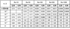
- FIG. 5 is a table showing an example of a simulation result of a relationship between Reynolds number Re, dimensionless transmittance / dimensionless plate thickness (K / ⁇ ), pressure loss, and heat transfer.
- 9 is a table showing a simulation result of a relation of a minimum dimensionless transmittance / dimensionless plate thickness (K / ⁇ ) to a Reynolds number Re in which a traveling wave is generated.
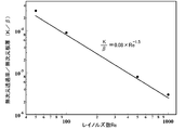
- FIG. 4 is an explanatory diagram showing an example of a relationship of a minimum dimensionless transmittance / dimensionless plate thickness (K / ⁇ ) to a Reynolds number Re at which a traveling wave occurs.
- FIG. 1 is an explanatory diagram schematically showing a configuration of a heat sink 20 as a heat transfer device of the embodiment.
- the heat sink 20 according to the embodiment includes a heat receiving unit 30 attached to the heating element, and a plurality of radiation fins 40 attached so as to be arranged in parallel with the heat receiving unit 30.
- the heat receiving portion 30 is formed in a plate shape from a metal material having good thermal conductivity such as aluminum, copper, and stainless steel.
- the heat radiating fins 40 are made of a porous metal such as aluminum, copper, stainless steel or the like having good thermal conductivity so as to transmit a heat transfer medium such as air or a refrigerant flowing as a flow path between the adjacent heat radiating fins 40. It is formed in a thin plate shape by a material.
- FIG. 2 is a schematic diagram schematically showing a state in which an unstable wave (traveling wave) is generated near the surface of the radiation fin 40.
- FIG. It is a schematic diagram which shows the high voltage
- the radiation fins 40 are formed of a porous material such as a metal that penetrates the heat transfer medium.
- FIG. 4 is an explanatory diagram showing a simulation result of the pressure of the heat transfer medium in the flow path sandwiching the radiation fins 40 using contour lines.
- a thick solid line at the center indicates the radiating fins 40
- a plus sign of -1.4 to 1.4 in the contour lines indicates that the pressure is higher than the average pressure of the heat transfer medium
- a minus sign indicates the heat transfer medium. Indicates that the pressure is lower than the average pressure.
- the pressure fluctuates in the order of the high pressure part, the low pressure part, the high pressure part, and the low pressure part from the left side. Section, high-pressure section, low-pressure section, and high-pressure section. For this reason, as shown by the arrows described in the heat radiation fins 40 in FIG.
- the heat transfer medium passes through the heat radiation fins 40 from the high-pressure part to the low-pressure part. Since waves alternately generated by the high-pressure portion and the low-pressure portion travel along the flow of the heat transfer medium, each portion of the radiating fin 40 transmits the heat transfer medium from one flow path side to the other flow path side and the other side. From the flow path side to one side is alternately performed. In such transmission of the heat transfer medium through the radiation fins 40, heat transfer occurs between the heat transfer medium and the radiation fins 40. For this reason, the heat transfer can be made higher than when the heat radiation fins 40 are formed of a material through which the heat transfer medium cannot pass.
- the unstable wave due to the Kelvin-Helmholtz instability has the effect of driving the fluid downstream, whereby the flow resistance can be kept relatively small.
- the pressure loss of the heat transfer medium flowing between the radiation fins 40 can be suppressed, and the heat transfer of the radiation fins 40 can be increased.
- FIG. 5 is an explanatory diagram schematically showing the dimensions of the radiation fins 40 and the flow velocity of the heat transfer medium flowing between the radiation fins 40 (flow path).
- the plate thickness of the radiation fin 40 is ⁇
- the interval (channel width) between the radiation fins 40 is 2H (half channel width is H)
- the bulk velocity (average flow velocity) of the heat transfer medium is Ub
- the total volume V of the radiation fins is
- the porosity, which is the ratio (Vv / V) of the volume Vv of the void, is ⁇
- the hydrodynamic diameter of the void (4Vv / S) is obtained by dividing four times the volume Vv of the void of the radiation fin 40 by the area S of the solid void interface of the radiation fin 40.
- FIG. 6 is a list showing simulation results of the relationship between Reynolds number Re, dimensionless transmittance / dimensionless plate thickness (K / ⁇ ), pressure loss, and heat transfer.
- FIG. 7 is a table showing a simulation result of a relationship of a minimum dimensionless transmittance / dimensionless plate thickness (K / ⁇ ) to a Reynolds number Re at which a traveling wave occurs.
- a hatched area indicates an area where a traveling wave is generated.
- the Reynolds number Re is 10
- the pressure loss and heat transfer do not increase unless K / ⁇ becomes infinite. This means that no traveling wave is generated.
- FIG. 8 is an explanatory diagram showing an example of the relationship of the minimum dimensionless transmittance / dimensionless plate thickness (K / ⁇ ) to the Reynolds number Re at which a traveling wave occurs.
- K / ⁇ dimensionless plate thickness
- four plots are the points shown in FIG. 7, and the straight line is a straight line drawn such that the four plots are included in the upper right area (the inequality sign of equation (4) is equalized).
- an unstable wave (traveling wave) due to Kelvin-Helmholtz instability does not occur in a region on the lower left side of the straight line in FIG. Therefore, in this region, it is difficult for the heat transfer medium to pass through the radiating fins 40, and it is difficult to contribute to heat transfer.
- the Reynolds number Re is preferably 50 or more (Re ⁇ 50). This condition is based on the fact that when the Reynolds number Re is less than 50, the heat transfer medium flows slowly, and it is often difficult to generate an unstable wave (traveling wave) due to Kelvin-Helmholtz instability. Further, it is preferable that the pore hydraulic diameter Dh is Dh ⁇ 0.1H. This condition is based on the fact that the pores through which the heat transfer medium of the radiating fins 40 penetrates are sufficiently smaller than the flow path dimensions that can be mechanically formed.
- the flow and heat transfer in the individual pores of the heat radiation fins 40 are not solved, but the average inside the heat radiation fins 40 is determined according to the dimensionless transmittance K. This is to establish the assumption that a typical flow (flow by permeation) occurs.
- the radiation fins 40 are formed of a porous material through which the heat transfer medium can pass, and the radiation fins 40 are generated by unstable waves (traveling waves) generated near the surface of the radiation fins 40.
- the transmission of the heat transfer medium from one channel side to the other channel side and the transmission from the other channel side to one side are performed alternately. Thereby, the pressure loss of the heat transfer medium flowing between the radiation fins 40 can be suppressed, and the heat transfer of the radiation fins 40 can be increased.
- the heat sink 20 according to the embodiment has been described as dissipating heat by the radiating fins 40. However, the heat sink 20 may dissipate cold heat, that is, may absorb heat.
- the heat transfer device of the present invention has been described with the heat sink 20 as an embodiment and applied to the radiation fins 40.
- a corrugated fin-type heat exchanger may be used as an embodiment of the heat transfer device of the present invention, and may be applied to a corrugated fin.
- a tube type heat exchanger through which a heat exchange medium flows may be used, and the heat transfer device may be applied to a fin attached to a tube.
- a fin attached to a corrugated fin or a tube may be an offset fin, and the offset fin may be applied to a portion of the offset fin that is arranged in parallel.
- the present invention is applicable to a heat transfer device manufacturing industry and the like.
Landscapes
- Engineering & Computer Science (AREA)
- Physics & Mathematics (AREA)
- Thermal Sciences (AREA)
- Mechanical Engineering (AREA)
- General Engineering & Computer Science (AREA)
- Geometry (AREA)
- Cooling Or The Like Of Electrical Apparatus (AREA)
- Cooling Or The Like Of Semiconductors Or Solid State Devices (AREA)
Abstract
伝熱装置における平行に配置された複数の伝熱フィンを、隣接する伝熱フィンの間を流路として流れる伝熱媒体を透過可能な多孔質材料により形成する。伝熱媒体を伝熱フィンの間を流路として流すと、伝熱媒体の伝熱フィンの面の近傍と遠方における主流方向速度分布の不均一性によって、ケルビン・ヘルムホルツ不安定に起因する進行波(圧力の高い部分と低い部分による波)が発生し、伝熱媒体が伝熱フィンを透過する現象を生じさせる。これにより、伝熱を高くすることができる。この進行波は、流体を駆動する効果を有しており、比較的小さい圧力損失で伝熱媒体を流路に流すことができる。これらの結果、伝熱フィンの間に流れる伝熱媒体の圧損を抑えて伝熱フィンの伝熱を高くすることができる。
Description
本発明は、伝熱装置に関し、詳しくは、平行に配置された複数の伝熱フィンを有する伝熱装置に関する。
従来、この種の技術としては、複数の放熱フィンを平行に配置したヒートシンクが提案されている(例えば、特許文献1参照)。このヒートシンクの放熱フィンは、アルミニウムやアルミニウム合金、銅などの熱伝導率の高い金属材料により板状に形成されている。また、放熱フィンには高い熱輸送性が求められることから、放熱フィンをグラファイト材料により形成するものも提案されている(例えば、特許文献2参照)。
また、複数のルーバを切り起こして形成されたコルゲートフィンを備える熱交換器も提案されている(例えば、特許文献3参照)。この熱交換器では、コルゲートフィンに複数のルーバを形成することにより、伝熱性能の向上を図っている。
上述の技術のように、放熱フィンやコルゲートフィンなどの伝熱フィンには高い伝熱性能が望まれる。このため、伝熱フィンの間隔を狭くたり、伝熱フィンの間に流れる空気や液体などの伝熱媒体の流速を大きくしたり、伝熱フィンに切り起こしを形成したり、伝熱フィンを波状に形成したりするなど種々の手法により伝熱を高める提案が行なわれているが、これらの多くの場合、伝熱媒体の圧損が過剰に大きくなってしまう。
本発明の伝熱装置は、伝熱フィンの間に流れる伝熱媒体の圧損を抑えて伝熱フィンの伝熱を高くすることを主目的とする。
本発明の伝熱装置は、上述の主目的を達成するために以下の手段を採った。
本発明の伝熱装置は、
平行に配置された複数の伝熱フィンを有する伝熱装置であって、
前記伝熱フィンは、隣接する伝熱フィンの間を流路として流れる伝熱媒体を透過可能な多孔質材料により形成されている、
ことを特徴とする。
平行に配置された複数の伝熱フィンを有する伝熱装置であって、
前記伝熱フィンは、隣接する伝熱フィンの間を流路として流れる伝熱媒体を透過可能な多孔質材料により形成されている、
ことを特徴とする。
本発明の伝熱装置では、伝熱媒体を平行に配置された伝熱フィンの間を流路として流すと、伝熱面近傍の低速領域と伝熱面遠方における高速領域との間の速度差により、ケルビン・ヘルムホルツ不安定性による不安定波が発生し、伝熱媒体の圧力が高い高圧部と圧力の低い低圧部とが交互に形成され、これが主流方向に伝播する進行波として下流側に流れる。伝熱フィンは伝熱媒体を透過可能な多孔質材料により形成されているから、高圧部では伝熱媒体が伝熱フィンを透過して隣接する流路に流出し、低圧部では隣接する流路から伝熱フィンを透過して流入する。この透過の際に伝熱媒体と伝熱フィンとに伝熱が生じる。こうした伝熱フィンで生成される進行波は、流れを下流へと推し進める効果を有しており、伝熱フィン間の流動抵抗を比較的小さく抑える効果があるとともに、流路内部の攪拌する効果によって伝熱促進が実現できる。この結果、伝熱フィンの間に流れる伝熱媒体の圧損を抑えて伝熱フィンの伝熱を高くすることができる。
本発明の伝熱装置において、前記伝熱フィンの間隔を2H、前記伝熱フィンの板厚をδとしたときに式(1)で示される無次元板厚βと、前記伝熱フィンの全体の体積における空隙の体積の比率である空隙率をε、前記伝熱フィンの空隙の体積の4倍を伝熱フィンの固体空隙界面の面積で除した空隙水力直径をDhとしたときに式(2)で表わされる無次元透過率Kと、前記伝熱媒体のバルク速度をUb、前記伝熱媒体の動粘性係数をνとしたときに式(3)で表わされるレイノルズ数Reと、を用いたときに式(4)を満たすものとしてもよい。こうすれば、伝熱フィンのサイズや間隔、伝熱媒体の種類に応じてより適正な伝熱装置を設計することができる。
β=δ/H (1)
K=(ε/32)・(Dh/H)2 (2)
Re=Ub・H/ν (3)
K/β>0.08×Re-1.5 (4)
K=(ε/32)・(Dh/H)2 (2)
Re=Ub・H/ν (3)
K/β>0.08×Re-1.5 (4)
こうした式(4)を満たす態様の本発明の伝熱装置において、レイノルズ数ReがRe≧50を満たすものとしてもよい。この条件は、レイノルズ数Reが50未満では伝熱媒体はゆっくり流れるため、ケルビン・ヘルムホルツ不安定性による進行波が生じない場合が多いことに基づいている。
また、式(4)を満たす態様の本発明の伝熱装置において、空隙水力直径DhがDh≦0.1Hを満たすものとしてもよい。この条件は、伝熱フィンの伝熱媒体が透過する孔が、機械的に形成する流路寸法に対して充分に小さいことに基づいている。即ち、伝熱における数値計算上において、伝熱フィンの個別の孔の中の流れや熱伝達を解くのではなく、透過率に応じて、伝熱フィン内部に平均的な流れが生じるものとの仮定を成立させるためである。
次に、本発明を実施するための形態について説明する。図1は、実施形態の伝熱装置としてのヒートシンク20の構成の概略を示す説明図である。実施形態のヒートシンク20は、発熱体に取り付けられる受熱部30と、受熱部30に平行に配置されるように取り付けられた複数の放熱フィン40と、を備える。
受熱部30は、アルミニウムや銅、ステンレスなどの熱伝導性が良好な金属材料などにより板状に形成されている。
放熱フィン40は、隣接する放熱フィン40との間を流路として流れる空気や冷媒などの伝熱媒体を透過するように、アルミニウムや銅、ステンレスなどの熱伝導性が良好な金属などによる多孔質材料によって、薄板状に形成されている。
次に、こうして構成されたヒートシンク20を発熱体に取り付け、複数の放熱フィン40の間に空気や冷媒(液体や気体の冷媒)などの伝熱媒体を流したときの機能について説明する。伝熱媒体を隣接する放熱フィン40の間を流路として流すと、伝熱媒体の放熱フィン40の表面近傍と遠方において主流速度が不均一になるため、ケルビン・ヘルムホルツ不安定性により、不安定波が発生じる。こうした不安定波は、伝熱媒体の放熱フィン40の流入部近傍の微小撹乱によって生じた圧力変動がその後増幅することにより発生し、流れ方向に移流する進行波となる。したがって、放熱フィン40の表面の近傍には、伝熱媒体の圧力の高い高圧部と圧力の低い低圧部とが交互に生じ、この高圧部と低圧部とが交互に生じる不安定波が伝熱媒体の流れ方向に進行する。図2は、放熱フィン40の表面の近傍に不安定波(進行波)が生じている状態を模式的に示す模式図であり、図3は、放熱フィン40の表面の近傍に生じた不安定波(進行波)における交互に生じる高圧部と低圧部とを模式的に示す模式図である。放熱フィン40は、上述したように、伝熱媒体を透過する金属などによる多孔質材料により形成されているから、放熱フィン40の表面において高圧部では、伝熱媒体が放熱フィン40を透過して隣の流路に流出し、逆に低圧部では、隣の流路の伝熱媒体が放熱フィン40を透過して流入する。高圧部や低圧部の分布は、全体的なバランスにより、放熱フィン40を挟む2つの流路における放熱フィン40の両表面の近傍では、図3に示すように、一方が高圧部となるときには放熱フィン40を挟んで対向する他方は低圧部となり、一方が低圧部となるときには他方は高圧部となる。図4は、放熱フィン40を挟む流路における伝熱媒体の圧力のシミュレーション結果を等高線を用いて示す説明図である。図中、中央の太実線は放熱フィン40を示し、等高線における-1.4~1.4のうちプラスの表示は伝熱媒体の平均圧力より高圧であることを示し、マイナス表示は伝熱媒体の平均圧力より低圧であることを示す。図示するように、放熱フィン40の図中上側では左側から高圧部、低圧部、高圧部、低圧部の順に圧力変動し、放熱フィンの図中下側では上側と対になるように左側から低圧部、高圧部、低圧部、高圧部の順に圧力変動する。このため、図3の放熱フィン40に記載された矢印に示すように、伝熱媒体は高圧部から低圧部に向けて放熱フィン40を透過する。こうした交互に生じる高圧部と低圧部とによる波は伝熱媒体の流れに沿って進行するから、放熱フィン40の各部では、伝熱媒体の一方の流路側から他方の流路側への透過と他方の流路側から一方側への透過とが交互に行なわれる。こうした伝熱媒体の放熱フィン40の透過では、伝熱媒体と放熱フィン40とに伝熱が生じる。このため、放熱フィン40を伝熱媒体が透過できない材料により形成する場合に比して伝熱を高くすることができる。一方、ケルビン・ヘルムホルツ不安定性による不安定波は、下流へ流体を駆動する効果があり、これにより流動抵抗を比較的小さく抑えることができる。これらの結果、放熱フィン40の間に流れる伝熱媒体の圧損を抑えて放熱フィン40の伝熱を高くすることができる。
次に、実施形態のヒートシンク20の放熱フィン40における好ましい条件について説明する。図5は、放熱フィン40の寸法や放熱フィン40の間(流路)に流れる伝熱媒体の流速を模式的に示す説明図である。いま、放熱フィン40の板厚をδ、放熱フィン40の間隔(チャネル幅)を2H(チャネル半幅をH)、伝熱媒体のバルク速度(平均流速)をUb、放熱フィンの全体の体積Vにおける空隙の体積Vvの比率(Vv/V)である空隙率をε、放熱フィン40の空隙の体積Vvの4倍を放熱フィン40の固体空隙界面の面積Sで除した空隙水力直径(4Vv/S)をDh、伝熱媒体の動粘性係数をνとしたときに、式(1)で示される無次元板厚βと、式(2)で表わされる無次元透過率Kと、式(3)で表わされるレイノルズ数Reと、を定義する。このとき、式(4)の条件を満たすことが好ましい。
β=δ/H (1)
K=(ε/32)・(Dh/H)2 (2)
Re=Ub・H/ν (3)
K/β>0.08×Re-1.5 (4)
K=(ε/32)・(Dh/H)2 (2)
Re=Ub・H/ν (3)
K/β>0.08×Re-1.5 (4)
図6は、レイノルズ数Reと無次元透過率/無次元板厚(K/β)と圧損と伝熱との関係のシミュレーション結果を示す一覧表である。図7は、進行波が生じるレイノルズ数Reに対する最小の無次元透過率/無次元板厚(K/β)の関係のシミュレーション結果を示す一覧表である。図6中、ハッチング領域は進行波が生じる領域を示す。レイノルズ数Reが10(RE=10)のときには、K/βが無限大にならないと圧損や伝熱は大きくならない。これは、進行波が生じていないことを意味している。レイノルズ数Reが50(RE=50)のときには、K/βが10-3~10-2の間の値(3.0×10-3)以上で圧損と伝熱とが大きくなる。これは、この値以上で進行波が生じていることを意味している。同様に、レイノルズ数Reが100(RE=100)、500(Re=500)、1000(Re=1000)のときには、K/βが10-4~10-5の間の値(9.0×10-4)以上、10-5~10-6の間の値(8.0×10-5)以上、10-5~10-6の間の値(3.0×10-5)以上で圧損と伝熱とが大きくなり、この値以上で進行波が生じる。
図8は、進行波が生じるレイノルズ数Reに対する最小の無次元透過率/無次元板厚(K/β)の関係の一例を示す説明図である。図中、4つのプロットは、図7に示すポイントであり、直線は、4つのプロットが右上領域に含まれるように作図した直線(式(4)の不等号を等号としたもの)である。シミュレーション結果では図8の直線より左下側の領域ではケルビン・ヘルムホルツ不安定性による不安定波(進行波)が生じない。このため、この領域では、伝熱媒体が放熱フィン40を透過することが困難となり、伝熱への寄与も困難となる。一方、図8の直線より右上側の領域ではケルビン・ヘルムホルツ不安定性による不安定波(進行波)が生じる。このため、この領域では、伝熱媒体が放熱フィン40を透過することになり、これが伝熱にも寄与する。
上述の式(4)の条件に加えて、レイノルズ数Reは50以上(Re≧50)であることが好ましい。この条件は、レイノルズ数Reが50未満では伝熱媒体はゆっくり流れるため、ケルビン・ヘルムホルツ不安定性による不安定波(進行波)の発生が困難となる場合が多いことに基づく。また、空隙水力直径DhがDh≦0.1Hであることが好ましい。この条件は、放熱フィン40の伝熱媒体が透過する細孔が機械的に形成することができる流路寸法に対して充分に小さいことに基づいている。即ち、放熱フィン40の伝熱における数値計算上において、放熱フィン40の個別の細孔の中の流れや熱伝達を解くのではなく、無次元透過率Kに応じて、放熱フィン40内部に平均的な流れ(透過による流れ)が生じるものとの仮定を成立させるためである。
以上説明した実施形態のヒートシンク20では、伝熱媒体が透過可能な多孔質材料により放熱フィン40を形成することにより、放熱フィン40の表面の近傍に生じる不安定波(進行波)によって放熱フィン40の各部において伝熱媒体の一方の流路側から他方の流路側への透過と他方の流路側から一方側への透過とが交互に行なわれる。これにより、放熱フィン40の間に流れる伝熱媒体の圧損を抑えて放熱フィン40の伝熱を高くすることができる。
実施形態のヒートシンク20では、放熱フィン40により放熱するものとして説明したが、冷熱を放熱するもの、即ち吸熱するものとしてもよい。
本発明の伝熱装置をヒートシンク20を実施形態とし、その放熱フィン40に適用して説明した。しかし、本発明の伝熱装置の実施形態としてコルゲートフィン型熱交換器を用い、コルゲートフィンに適用するものとしてもよい。また、本発明の伝熱装置の実施形態として熱交換媒体を流通するチューブ型の熱交換器を用い、チューブに取り付けたフィンに適用するものとしてもよい。或いは、コルゲートフィンやチューブに取り付けたフィンをオフセットフィンとし、このオフセットフィンにおける平行に配置された部分に適用するものとしてもよい。
以上、本発明を実施するための形態について実施例を用いて説明したが、本発明はこうした実施例に何等限定されるものではなく、本発明の要旨を逸脱しない範囲内において、種々なる形態で実施し得ることは勿論である。
本発明は、伝熱装置の製造産業などに利用可能である。
Claims (4)
- 平行に配置された複数の伝熱フィンを有する伝熱装置であって、
前記伝熱フィンは、隣接する伝熱フィンの間を流路として流れる伝熱媒体を透過可能な多孔質材料により形成されている、
ことを特徴とする伝熱装置。 - 請求項1記載の伝熱装置であって、
前記伝熱フィンの間隔を2H、前記伝熱フィンの板厚をδとしたときに式(1)で示される無次元板厚βと、前記伝熱フィンの全体の体積における空隙の体積の比率である空隙率をε、前記伝熱フィンの空隙の体積の4倍を伝熱フィンの固体空隙界面の面積で除した空隙水力直径をDhとしたときに式(2)で表わされる無次元透過率Kと、前記伝熱媒体のバルク速度をUb、前記伝熱媒体の動粘性係数をνとしたときに式(3)で表わされるレイノルズ数Reと、を用いたときに式(4)を満たす、
伝熱装置。
β=δ/H (1)
K=(ε/32)・(Dh/H)2 (2)
Re=Ub・H/ν (3)
K/β>0.08×Re-1.5 (4) - 請求項2記載の伝熱装置であって、
レイノルズ数ReがRe≧50を満たす、
伝熱装置。 - 請求項2または3記載の伝熱装置であって、
空隙水力直径DhがDh≦0.1Hを満たす、
伝熱装置。
Applications Claiming Priority (2)
| Application Number | Priority Date | Filing Date | Title |
|---|---|---|---|
| JP2018-150074 | 2018-08-09 | ||
| JP2018150074A JP7148118B2 (ja) | 2018-08-09 | 2018-08-09 | 伝熱装置 |
Publications (1)
| Publication Number | Publication Date |
|---|---|
| WO2020031856A1 true WO2020031856A1 (ja) | 2020-02-13 |
Family
ID=69413673
Family Applications (1)
| Application Number | Title | Priority Date | Filing Date |
|---|---|---|---|
| PCT/JP2019/030285 Ceased WO2020031856A1 (ja) | 2018-08-09 | 2019-08-01 | 伝熱装置 |
Country Status (2)
| Country | Link |
|---|---|
| JP (1) | JP7148118B2 (ja) |
| WO (1) | WO2020031856A1 (ja) |
Cited By (1)
| Publication number | Priority date | Publication date | Assignee | Title |
|---|---|---|---|---|
| CN113551870A (zh) * | 2021-06-23 | 2021-10-26 | 中国核动力研究设计院 | 一种对并联通道流动失稳行为影响机制的表征方法及系统 |
Citations (8)
| Publication number | Priority date | Publication date | Assignee | Title |
|---|---|---|---|---|
| JPS5272964A (en) * | 1975-12-15 | 1977-06-18 | Matsushita Refrig Co | Heat exchanger |
| JPS57178985U (ja) * | 1981-05-08 | 1982-11-12 | ||
| JP2002057255A (ja) * | 2000-08-11 | 2002-02-22 | Nec Corp | フィン間隔算出装置および方法 |
| JP2003037226A (ja) * | 2001-06-01 | 2003-02-07 | Delphi Technologies Inc | エレクトロニクス冷却のための高性能ヒート・シンク |
| JP2003068944A (ja) * | 2001-08-28 | 2003-03-07 | Nec Corp | 強制対流冷却型ヒートシンクの最適フィン間隔算出方法と装置ならびにヒートシンク |
| US20090321046A1 (en) * | 2008-06-30 | 2009-12-31 | Alcatel-Lucent Technologies Inc. | Flow diverters to enhance heat sink performance |
| CN201382734Y (zh) * | 2009-04-03 | 2010-01-13 | 李明烈 | 射出成型的多孔性陶瓷散热器结构 |
| JP2016174025A (ja) * | 2015-03-16 | 2016-09-29 | 日立化成株式会社 | 放熱フィンおよびそれを搭載したヒートシンク、モジュール |
Family Cites Families (1)
| Publication number | Priority date | Publication date | Assignee | Title |
|---|---|---|---|---|
| JPS5262964A (en) * | 1975-11-18 | 1977-05-24 | Stanley Electric Co Ltd | Ultrasonic washing apparatus using jet stream |
-
2018
- 2018-08-09 JP JP2018150074A patent/JP7148118B2/ja active Active
-
2019
- 2019-08-01 WO PCT/JP2019/030285 patent/WO2020031856A1/ja not_active Ceased
Patent Citations (8)
| Publication number | Priority date | Publication date | Assignee | Title |
|---|---|---|---|---|
| JPS5272964A (en) * | 1975-12-15 | 1977-06-18 | Matsushita Refrig Co | Heat exchanger |
| JPS57178985U (ja) * | 1981-05-08 | 1982-11-12 | ||
| JP2002057255A (ja) * | 2000-08-11 | 2002-02-22 | Nec Corp | フィン間隔算出装置および方法 |
| JP2003037226A (ja) * | 2001-06-01 | 2003-02-07 | Delphi Technologies Inc | エレクトロニクス冷却のための高性能ヒート・シンク |
| JP2003068944A (ja) * | 2001-08-28 | 2003-03-07 | Nec Corp | 強制対流冷却型ヒートシンクの最適フィン間隔算出方法と装置ならびにヒートシンク |
| US20090321046A1 (en) * | 2008-06-30 | 2009-12-31 | Alcatel-Lucent Technologies Inc. | Flow diverters to enhance heat sink performance |
| CN201382734Y (zh) * | 2009-04-03 | 2010-01-13 | 李明烈 | 射出成型的多孔性陶瓷散热器结构 |
| JP2016174025A (ja) * | 2015-03-16 | 2016-09-29 | 日立化成株式会社 | 放熱フィンおよびそれを搭載したヒートシンク、モジュール |
Cited By (1)
| Publication number | Priority date | Publication date | Assignee | Title |
|---|---|---|---|---|
| CN113551870A (zh) * | 2021-06-23 | 2021-10-26 | 中国核动力研究设计院 | 一种对并联通道流动失稳行为影响机制的表征方法及系统 |
Also Published As
| Publication number | Publication date |
|---|---|
| JP2020026889A (ja) | 2020-02-20 |
| JP7148118B2 (ja) | 2022-10-05 |
Similar Documents
| Publication | Publication Date | Title |
|---|---|---|
| CN110637363B (zh) | 散热器和用于生产该散热器的方法 | |
| Riofrío et al. | State of the art of efficient pumped two-phase flow cooling technologies | |
| US9689620B2 (en) | Heat exchanger | |
| US20150226496A1 (en) | Fin of heat exchanger and heat exchanger | |
| EP2840875A1 (en) | Liquid-cooled radiator | |
| JPH0514194B2 (ja) | ||
| US11280554B2 (en) | Fractal heat exchanger with bypass | |
| JPWO2018012558A1 (ja) | 積層型ヒートシンクのコア | |
| CN101738119A (zh) | 热管嵌合槽道吸液芯 | |
| JP5205095B2 (ja) | オイルクーラ | |
| JPWO2014038038A1 (ja) | 空気熱交換器 | |
| JP7148118B2 (ja) | 伝熱装置 | |
| WO2017038380A1 (ja) | 熱交換器 | |
| US20190154351A1 (en) | Shear flow condenser | |
| JP2012007778A (ja) | 熱交換器 | |
| JP2018017424A (ja) | 熱交換器の製造方法 | |
| JP2007309533A (ja) | フィンチューブ熱交換器 | |
| JP2019184129A (ja) | 熱交換器 | |
| JP6239997B2 (ja) | 冷却器 | |
| JP2020143873A (ja) | 熱交換器の製造方法及び熱交換器 | |
| JP6874823B1 (ja) | 冷却構造及びヒートシンク | |
| JP2007113793A (ja) | エバポレータ | |
| JP2009052874A (ja) | プレートフィン式熱交換器 | |
| CN119929167B (zh) | 变径板翅式油冷器 | |
| US20140373960A1 (en) | Bi-channel coolant tube having crossover channels to allow coolant interaction |
Legal Events
| Date | Code | Title | Description |
|---|---|---|---|
| 121 | Ep: the epo has been informed by wipo that ep was designated in this application |
Ref document number: 19846165 Country of ref document: EP Kind code of ref document: A1 |
|
| NENP | Non-entry into the national phase |
Ref country code: DE |
|
| 122 | Ep: pct application non-entry in european phase |
Ref document number: 19846165 Country of ref document: EP Kind code of ref document: A1 |