WO2020031801A1 - 密閉型電動圧縮機及びこれを用いた冷凍空調装置 - Google Patents
密閉型電動圧縮機及びこれを用いた冷凍空調装置 Download PDFInfo
- Publication number
- WO2020031801A1 WO2020031801A1 PCT/JP2019/029976 JP2019029976W WO2020031801A1 WO 2020031801 A1 WO2020031801 A1 WO 2020031801A1 JP 2019029976 W JP2019029976 W JP 2019029976W WO 2020031801 A1 WO2020031801 A1 WO 2020031801A1
- Authority
- WO
- WIPO (PCT)
- Prior art keywords
- electric compressor
- hermetic electric
- refrigerant
- trifluoroiodomethane
- insulating film
- Prior art date
- Legal status (The legal status is an assumption and is not a legal conclusion. Google has not performed a legal analysis and makes no representation as to the accuracy of the status listed.)
- Ceased
Links
Images
Classifications
-
- F—MECHANICAL ENGINEERING; LIGHTING; HEATING; WEAPONS; BLASTING
- F04—POSITIVE - DISPLACEMENT MACHINES FOR LIQUIDS; PUMPS FOR LIQUIDS OR ELASTIC FLUIDS
- F04B—POSITIVE-DISPLACEMENT MACHINES FOR LIQUIDS; PUMPS
- F04B39/00—Component parts, details, or accessories, of pumps or pumping systems specially adapted for elastic fluids, not otherwise provided for in, or of interest apart from, groups F04B25/00 - F04B37/00
-
- F—MECHANICAL ENGINEERING; LIGHTING; HEATING; WEAPONS; BLASTING
- F04—POSITIVE - DISPLACEMENT MACHINES FOR LIQUIDS; PUMPS FOR LIQUIDS OR ELASTIC FLUIDS
- F04C—ROTARY-PISTON, OR OSCILLATING-PISTON, POSITIVE-DISPLACEMENT MACHINES FOR LIQUIDS; ROTARY-PISTON, OR OSCILLATING-PISTON, POSITIVE-DISPLACEMENT PUMPS
- F04C23/00—Combinations of two or more pumps, each being of rotary-piston or oscillating-piston type, specially adapted for elastic fluids; Pumping installations specially adapted for elastic fluids; Multi-stage pumps specially adapted for elastic fluids
- F04C23/02—Pumps characterised by combination with, or adaptation to, specific driving engines or motors
-
- F—MECHANICAL ENGINEERING; LIGHTING; HEATING; WEAPONS; BLASTING
- F04—POSITIVE - DISPLACEMENT MACHINES FOR LIQUIDS; PUMPS FOR LIQUIDS OR ELASTIC FLUIDS
- F04C—ROTARY-PISTON, OR OSCILLATING-PISTON, POSITIVE-DISPLACEMENT MACHINES FOR LIQUIDS; ROTARY-PISTON, OR OSCILLATING-PISTON, POSITIVE-DISPLACEMENT PUMPS
- F04C29/00—Component parts, details or accessories of pumps or pumping installations, not provided for in groups F04C18/00 - F04C28/00
-
- F—MECHANICAL ENGINEERING; LIGHTING; HEATING; WEAPONS; BLASTING
- F25—REFRIGERATION OR COOLING; COMBINED HEATING AND REFRIGERATION SYSTEMS; HEAT PUMP SYSTEMS; MANUFACTURE OR STORAGE OF ICE; LIQUEFACTION SOLIDIFICATION OF GASES
- F25B—REFRIGERATION MACHINES, PLANTS OR SYSTEMS; COMBINED HEATING AND REFRIGERATION SYSTEMS; HEAT PUMP SYSTEMS
- F25B1/00—Compression machines, plants or systems with non-reversible cycle
-
- F—MECHANICAL ENGINEERING; LIGHTING; HEATING; WEAPONS; BLASTING
- F25—REFRIGERATION OR COOLING; COMBINED HEATING AND REFRIGERATION SYSTEMS; HEAT PUMP SYSTEMS; MANUFACTURE OR STORAGE OF ICE; LIQUEFACTION SOLIDIFICATION OF GASES
- F25B—REFRIGERATION MACHINES, PLANTS OR SYSTEMS; COMBINED HEATING AND REFRIGERATION SYSTEMS; HEAT PUMP SYSTEMS
- F25B1/00—Compression machines, plants or systems with non-reversible cycle
- F25B1/04—Compression machines, plants or systems with non-reversible cycle with compressor of rotary type
-
- H—ELECTRICITY
- H02—GENERATION; CONVERSION OR DISTRIBUTION OF ELECTRIC POWER
- H02K—DYNAMO-ELECTRIC MACHINES
- H02K3/00—Details of windings
- H02K3/30—Windings characterised by the insulating material
Definitions
- the present invention relates to a hermetic electric compressor and a refrigeration / air-conditioning apparatus using the same, and particularly to a refrigeration cycle of a refrigeration / air-conditioning apparatus (for example, an air conditioner, a refrigerator, a freezer, a refrigeration / refrigeration showcase, etc.) and a heat pump hot water supply apparatus. It is suitable as a hermetic electric compressor used as a component device of (1).
- R134a As a refrigerant used for a refrigerator, an air conditioner, a refrigerator, and the like, for example, R134a, R410A, R407C, and the like are used. Although these refrigerants have little effect on the ozone layer, they have a large global warming potential (GWP).
- GWP global warming potential
- R32 difluoromethane
- R32 has been proposed as an alternative refrigerant. R32 has a global warming potential of about one third of that of R410A.
- HHFO1234yf described in Patent Documents 1 and 2 alone or a mixed refrigerant of HFO1234yf and HFC32 can reduce GWP, but is slightly flammable. Further, HFO1234yf cannot exhibit the same performance as a refrigerant currently used as a refrigerant for an air conditioner. For this reason, there is a problem that it is difficult to employ a large-sized air conditioner such as a multi air conditioner for a building, because a large amount of refrigerant is used.
- the temperature of the hermetic electric compressor used in a refrigeration / air-conditioning device such as an air conditioner is high because the compressor discharge temperature is high.
- the insulating film of the electric motor (motor) is hydrolyzed and deteriorated due to moisture contained in the cycle.
- Patent Document 1 discloses a compressor characterized by using a material of PPS (polyphenylene sulfide) or LCP (liquid crystal polymer) as a resin insulating material of a motor. Further, Patent Document 2 discloses that an organic insulating material in a compressor uses a material that is not physically and scientifically deteriorated.
- PPS polyphenylene sulfide
- LCP liquid crystal polymer
- Patent Document 1 since the material of PPS and LCP described in Patent Document 1 has high hardness, the formability of the insulating film of the electric motor is deteriorated, and when the coil is wound, the coil surface is damaged at the end face of the film. There are issues. Furthermore, since PPS and LCP are expensive materials, there is also a problem that manufacturing costs are high.
- An object of the present invention is to provide a hermetic electric compressor and a refrigeration using the hermetic compressor, which can suppress hydrolysis and deterioration of a resin insulation material of an electric motor while using a flame retardant refrigerant having a low global warming potential. It is to obtain an air conditioner.
- the present invention provides, in a closed container, a high-pressure chamber type hermetic electric compressor including a compression mechanism that compresses a refrigerant and an electric motor that drives the compression mechanism, wherein the electric motor is It has a stator and a rotor, and uses a material of polyethylene terephthalate (PET) or polyethylene naphthalate (PEN) as a resin insulating material used for the stator, and has a low global warming potential as the refrigerant and It is characterized by using a flame-retardant, water-absorbing refrigerant, for example, trifluoroiodomethane (CF 3 I) alone or a mixed refrigerant containing the trifluoroiodomethane (CF 3 I).
- PET polyethylene terephthalate
- PEN polyethylene naphthalate
- Another feature of the present invention is the refrigeration and air-conditioning system in which a hermetic electric compressor, an outdoor heat exchanger, an expansion valve, and an indoor heat exchanger are sequentially connected by refrigerant piping to form a refrigeration cycle. It is assumed that trifluoroiodomethane (CF 3 I) alone or a mixed refrigerant containing the refrigerant is sealed as the refrigerant circulating in the cycle, and the above-mentioned closed electric compressor is used as the closed electric compressor.
- CF 3 I trifluoroiodomethane
- the hermetic-type electric compressor which can suppress that the resin insulation material of an electric motor is hydrolyzed and deteriorated while using a flame retardant refrigerant with a low global warming coefficient, and refrigeration using the same. There is an effect that an air conditioner can be obtained.
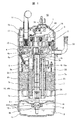
- FIG. 1 is a longitudinal sectional view illustrating an overall configuration of a hermetic electric compressor according to Embodiment 1 of the present invention.
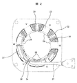
- FIG. 2 is a partial cross-sectional plan view illustrating a winding structure of a stator of the hermetic electric compressor illustrated in FIG. 1.
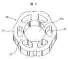
- FIG. 2 is a perspective view showing a stator core of the electric motor shown in FIG. 1.
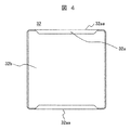
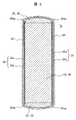
- FIG. 3 is a development view of the insulating film shown in FIG. 2. It is sectional drawing in the circumferential direction of the teeth part of a stator core, and the trunk
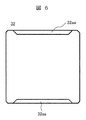
- FIG. 4 is a development view illustrating another example of the insulating film illustrated in FIG. 2.
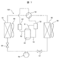
- FIG. 4 is a configuration diagram of a refrigeration cycle of a refrigeration air conditioner according to Embodiment 2 of the present invention.
- the present invention can exhibit sufficient capacity as a refrigerant for a refrigeration air conditioner, and suppresses degradation of an insulating film of a motor by hydrolysis while using a flame retardant refrigerant having a low global warming potential (GWP).
- GWP global warming potential
- the present invention relates to a high-pressure chamber-type hermetic electric compressor including a compression mechanism for compressing a refrigerant and an electric motor for driving the compression mechanism in an airtight container, wherein the electric motor comprises a stator and a rotor.
- the electric motor comprises a stator and a rotor.
- a material made of polyethylene terephthalate (PET) or polyethylene naphthalate (PEN) is used as a resin insulating material used for the stator, and the refrigerant is low GWP, flame-retardant, and water-absorbent. It uses a certain refrigerant.
- flame-retardant and water-absorbing refrigerant, non-combustible (flame-retardant) trifluoroiodomethane (CF 3 I) is used alone or a mixed refrigerant containing the refrigerant is used.
- a mixed refrigerant it is preferable to include trifluoroiodomethane (CF 3 I) and difluoromethane (HFC32).
- appropriate GWP, non-flammable, to obtain the vapor pressure preferably includes trifluoroiodomethane (CF 3 I) more than 30 wt%, to include trifluoroiodomethane the (CF 3 I) 30 ⁇ 50wt % More preferably, it is preferable that the mixed refrigerant contains 40 to 60% by weight of difluoromethane (HFC32). For the same reason, the mixed refrigerant preferably contains 85 to 95 wt% of trifluoroiodomethane (CF 3 I) and difluoromethane (HFC32) in total.
- the mixed refrigerant may further include pentafluoroethane (HFC125), and the pentafluoroethane is preferably contained in the mixed refrigerant in an amount of 5 to 15 wt%.
- HFC125 pentafluoroethane
- the stator of the electric motor includes a teeth portion around which a coil is wound, and a slot provided between the teeth portion and in which the coil is arranged.In the slot, an insulating film as a resin insulating material is inserted and arranged. The coil is wound around the teeth via the insulating film.
- the insulating film it is preferable to use polyethylene terephthalate that can maintain the elongation retention at 50% in an atmosphere of high-pressure steam at 140 ° C. for 7.5 hours or more.
- Patent Document 1 discloses that PPS (polyphenylene sulfide) or LCP (liquid crystal polymer) is used as a resin insulating material used for a stator of an electric motor.
- PPS and LCP materials have high hardness, and when used as an insulating film of a stator in an electric motor, formability deteriorates. When a coil is wound, there is a problem that the coil surface is damaged at the end face of the film. Furthermore, PPS and LCP are expensive materials, and there is a problem that the manufacturing cost is high.
- a material such as polyethylene terephthalate (PET) or polyethylene naphthalate (PEN) is used for the insulating film of the stator
- PET polyethylene terephthalate
- PEN polyethylene naphthalate
- a compressor using HFC32 mixed refrigerant increases the discharge temperature of the compressor. Therefore, the temperature of the inside of the closed container in the discharge gas atmosphere becomes high, and the moisture contained in the refrigeration cycle promotes the hydrolysis of the insulating film and rapidly deteriorates.
- HFO1234yf and HFC32 are slightly flammable refrigerants, there is a problem that it is difficult to employ them in large air conditioners such as multi-air conditioners for buildings, which require a large amount of refrigerant. Furthermore, there is another problem that when HFO1234yf is used alone as a refrigerant, it cannot exhibit sufficient performance as a refrigerant for a refrigeration air conditioner such as a multi air conditioner for a building or a room air conditioner.
- a low GWP, flame-retardant, water-absorbent refrigerant such as trifluoroiodomethane (CF 3 I) alone or a mixed refrigerant containing the refrigerant is used as the refrigerant. ing. Therefore, a hermetic electric compressor can be obtained in which a resin insulating material such as an insulating film of a motor is hydrolyzed and deteriorated while using a low-GWP, flame-retardant refrigerant.
- trifluoroiodomethane has a high adiabatic index and a high compressor discharge temperature, it has water absorption, so that the refrigerant absorbs water mixed in the refrigeration cycle and reduces the amount of water in the refrigeration cycle.
- a material such as polyethylene terephthalate (PET) or polyethylene naphthalate (PEN) is used for a resin insulating material such as an insulating film used for an electric motor
- PET polyethylene terephthalate
- PEN polyethylene naphthalate
- these materials have hydrolytic properties.
- the water in the refrigeration cycle is absorbed by the refrigerant, even when the temperature of the compressor becomes high, the resin insulating material is unlikely to undergo hydrolysis. Thereby, it is possible to prevent or suppress the resin insulating material such as the insulating film of the electric motor from being hydrolyzed and deteriorated, so that a failure can be avoided and a highly reliable hermetic electric compressor can be obtained. .
- the material of polyethylene terephthalate or polyethylene naphthalate can be used for the insulating film that is the resin insulating material of the electric motor in the compressor, an inexpensive insulating film having good moldability (workability) can be used. There is also an effect.
- the refrigerant By using a mixed refrigerant containing trifluoroiodomethane (CF 3 I) and difluoromethane (HFC32) as the mixed refrigerant, the refrigerant exhibits a sufficient capacity as a refrigerant for a refrigeration air conditioner such as a large air conditioner. It is possible to obtain a highly efficient and highly reliable hermetic electric compressor.
- CF 3 I trifluoroiodomethane
- HFC32 difluoromethane
- polyol ester (POE) oil or polyvinyl ether (PVE) oil which is a highly water-absorbing refrigeration oil, is used as the refrigeration oil, the amount of water in the refrigeration cycle can be further reduced. Hydrolysis of the resinous insulating material can be further suppressed.
- FIG. 1 is a longitudinal sectional view showing the overall configuration of the hermetic electric compressor according to the first embodiment.
- the hermetic electric compressor of the present embodiment includes a refrigeration cycle (refrigerant) constituting an air conditioner as a refrigeration / air-conditioning apparatus. Circuit). That is, in the air conditioner, a hermetic electric compressor, an outdoor heat exchanger, a four-way switching valve, an expansion valve, and an indoor heat exchanger are sequentially connected by a refrigerant pipe to constitute a refrigeration cycle.
- a refrigeration cycle refrigerant
- the refrigerant flowing through the refrigeration cycle is trifluoroiodomethane (CF 3 I), which is a low-GWP, flame-retardant, water-absorbing refrigerant, and a mixed refrigerant containing difluoromethane (HFC32).
- CF 3 I trifluoroiodomethane
- HFC32 a mixed refrigerant containing difluoromethane
- the closed container 1 includes a cylindrical tubular portion 1a, a lid portion 1b and a bottom portion 1c attached to the upper and lower portions of the tubular portion 1a by welding, and the inside thereof is a high-pressure sealed space.
- the compression mechanism 2 and the electric motor 7 are housed in the closed container 1, and an oil reservoir 9 is formed at the bottom of the closed container 1.
- the oil sump 9 stores a refrigerating machine oil (oil) 8 composed of ether-based or ester-based refrigerating machine oil.
- a refrigerating machine oil (oil) 8 composed of ether-based or ester-based refrigerating machine oil.
- a polyol ester (POE) oil or a polyvinyl ether (PVE) oil is used as the refrigerator oil.
- the oil level of the refrigerating machine oil 8 is set so as to be located above an auxiliary bearing 15 that supports a lower portion of the rotating shaft 6 that transmits the driving force of the electric motor 7 to the compression mechanism 2.
- Reference numeral 11 denotes a suction pipe attached through the lid 1b of the closed container 1
- reference numeral 22 denotes a discharge pipe attached through the cylindrical portion 1a of the closed container 1.
- the discharge pipe 22 is disposed immediately below the compression mechanism 2 and is provided so as to protrude toward the center in the closed casing 1.
- the tip of the discharge pipe 22 is located closer to the outer peripheral surface of the end coil 17 in the electric motor 7. It is installed so as to protrude to the center and open.
- the compression mechanism 2 is provided at an upper portion in the closed container 1, and sucks and compresses a gas refrigerant flowing through a refrigeration cycle and discharges the compressed gas into the closed container 1.
- a mixed refrigerant containing trifluoroiodomethane (CF 3 I) and difluoromethane (HFC32) is used as the refrigerant.
- the compression mechanism 2 includes a fixed scroll 3, an orbiting scroll 4, a frame 5, and an Oldham ring 10 as main components.
- the fixed scroll 3 is formed by erection of a spiral wrap on an end plate, and is bolted on the frame 5.
- a suction port 12 is provided at a peripheral portion of the fixed scroll 3, and a discharge port 14 is provided at a central portion.
- the suction port 12 communicates with the suction pipe 11, and the discharge port 14 communicates with a discharge chamber 40 above the compression mechanism 2 in the closed container 1.
- the orbiting scroll 4 is configured by erecting a spiral wrap on an end plate, and the orbiting scroll 4 is disposed so as to be sandwiched between the fixed scroll 3 and the frame 5,
- the compression chamber is formed by meshing the scroll 3 and the orbiting scroll 4.
- a boss portion 4b into which the orbiting bearing 4a is incorporated is provided on the back side (the side opposite to the fixed scroll) of the orbiting scroll 4.
- An eccentric pin 6a of the rotary shaft 6 is fitted to the orbiting bearing 4a to drive the orbiting scroll 4 eccentrically.
- the Oldham ring 10 constitutes a rotation restricting mechanism of the orbiting scroll 4, and is provided between the orbiting scroll 4 and the frame 5 to prevent the orbiting scroll 4 from rotating and form a circular orbit. It is for exercise.
- the frame 5 is fixed to the closed vessel 1 by welding, and supports the fixed scroll 3, the Oldham ring 10, and the orbiting scroll 4. At the center of the frame 5, a cylindrical portion 5a protruding downward is provided. A main bearing 5b for supporting the rotating shaft 6 is provided in the cylindrical portion 5a.
- a plurality of discharge gas passages are formed in the outer peripheral portions of the fixed scroll 3 and the frame 5 to communicate the space above the fixed scroll 3 (discharge chamber 40) and the space below the frame 5.
- the electric motor 7 has a rotor 7a integrally formed on the rotating shaft 6 by shrink fitting or the like and a stator 7b fixed on the inner surface of the sealed container 1 by shrink fitting or the like as main components. Is mounted with a balance weight 16. That is, an upper balance weight (compression mechanism side balance weight) 16a is mounted on the upper end face of the rotor 7a, and a lower balance weight (anti-compression mechanism side balance weight) 16b is mounted on the lower end face. These upper and lower balance weights 16a, 16b are fixed to the rotor 7a by a plurality of rivets, respectively.
- the stator 7b includes a stator iron core (hereinafter, also simply referred to as an iron core) 23 for efficiently transmitting a rotating magnetic field, and a plurality of conductors wound around the iron core 23 and supplying a current to generate a rotating magnetic field.
- Main components are a coil (stator winding) 24 and resin-insulated insulators 26 provided at both axial ends of the iron core 23 and used for insulation between the coil 24 and the iron core 23.
- the two insulators 26 provided at both ends in the axial direction of the iron core 23 are arranged to face each other with the iron core 23 interposed therebetween.
- the coil 24 is wound around the iron core 23 in a concentrated winding manner.
- a number of notches (not shown) are formed in the outer periphery of the stator 7b in the axial direction over the entire periphery, and a discharge gas passage is also formed between the notch and the closed container 1.
- the rotor 7a has a rotor core (hereinafter, also simply referred to as an iron core) 25 and a permanent magnet built in the iron core 25 as main components, and converts a rotating magnetic field from the stator 7b into a rotating motion.
- the rotary shaft 6 is rotated.
- the rotor 7a is rotatably disposed in a central hole 23a (see FIG. 3) of the iron core 23 of the stator 7b.
- the rotating shaft 6 is inserted and fitted into a central hole of the rotor 7a, and is integrated with the rotor 7a.
- One end (upper end) of the rotating shaft 6 is extended from the rotor 7a to the compression mechanism 2 side, and the eccentric pin 6a formed at the end of the rotating shaft 6 is connected to the compression mechanism. 2.
- an eccentric force is applied to the eccentric pin 6a by the compression operation of the compression mechanism 2.
- the other end (lower end) of the rotary shaft 6 extends from the rotor 7a to the oil reservoir 9 at the bottom of the closed casing 1.
- the rotating shaft 6 is supported by the main bearing 5b and the sub bearing 15 on both sides of the rotor 7a, and is configured to be stably rotatable.
- the auxiliary bearing 15 is supported by a support member 41 fixed to the closed container 1 by welding and is immersed in the refrigeration oil 8.
- the rotary shaft 6 is provided with a through-hole 6b for supplying the refrigerating machine oil 8 at the bottom of the closed container 1 to each of the bearings and the sliding parts. It is sucked up to the compression mechanism 2 side through 6b.
- the refrigerating machine oil 8 sucked up to the compression mechanism 2 side is supplied to the orbiting bearing 4a and the main bearing 5b, and at the same time, to each sliding portion of the compression mechanism 2 (the sliding portion of the Oldham ring 10 and the two scrolls 3). , 4).
- the refrigerating machine oil 8 supplied to the sliding portion of the compression mechanism 2 is discharged into the discharge chamber 40 from the discharge port 14 provided at the center of the fixed scroll 3 together with the refrigerant gas.
- the stator core 23 includes six teeth portions 28 extending in the motor axial direction, and a total of six slots 33 are formed between the tooth portions 28.
- an insulating film 32 as a resin insulating material is inserted into each slot 33 by bending and inserting the coil (stator winding) 24 into the teeth of the stator core 23 via the insulating film 32. It is directly wound around each of the portions 28.
- the insulating film 32 is made of polyethylene terephthalate (PET) or polyethylene naphthalate (PEN).
- windings (coils 24) having different phases are wound around the adjacent teeth portions 28, and one slot 33 Are present in different phases.
- the coil (stator winding) 24 wound around the stator core 23 is connected to a lead wire 34, and the lead wire 34 is connected to a hermetic terminal 35 (see FIG. 1) provided in the closed casing 1 of the hermetic electric compressor 50. )It is connected to the.
- FIG. 3 is a perspective view of the stator core (stator core) 23 of the electric motor 7 shown in FIG. As shown in FIG.
- the stator core 23 is formed of a plurality of laminated steel plates, and has an annular portion 27 on the outer peripheral side and projects radially inward from the inner peripheral surface of the annular portion 27, and has a circumferential direction. Are provided with teeth 28 arranged at equal intervals.
- Reference numeral 23a denotes a central hole of the stator core 23, and reference numeral 33 denotes a slot provided between the teeth portions 28 and in which the coil 24 (see FIGS. 1 and 2) is disposed.
- An insulating film 32 as a resin insulating material is inserted into the slot 33 and the coil 24 is wound around the teeth portion 28 via the insulating film 32.
- the electric motor 7 is a so-called 4-pole, 6-slot, and the coil 24 (see FIGS. 1 and 2) is intensively wound around one tooth portion 28 without straddling a plurality of the tooth portions 28.
- the so-called concentrated winding method is adopted.
- FIG. 4 is an exploded view of the insulating film 32 shown in FIG. 2.
- the insulating film 32 is inserted into each slot 33 of the stator core 23 shown in FIG. It is wound around the teeth portion 28 and arranged in the slot 33. That is, the insulating film 32 is bent so as to conform to the shape of the slot 33 formed between the teeth 28 of the stator core 23 shown in FIG.
- FIG. 5 is a sectional view of the teeth 28 of the stator core 23 and the trunk 30 of the insulator 26 in the circumferential direction.
- an insulating film 32 shown in FIG. 4 is arranged in a gap between the teeth 28 of the stator core 23 and the coil 24.
- the insulating film 32 is composed of a plurality of films 32a and 32b, and the coil 24 is connected to the teeth of the stator core 23 through the insulating film 32 composed of the plurality of films 32a and 32b. It is wound around the part 28.
- the insulating film 32 (films 32a and 32b) is made of polyethylene terephthalate (PET) or polyethylene naphthalate (PEN), and is a material that is inexpensive, has good workability, and has excellent heat resistance.
- the insulating film 32 is formed by two ends of the film 32a on the coil 24 side (upper and lower ends) among the films 32a and 32b formed of the plurality of insulating materials.
- a folded portion 32aa is formed in the upper and lower folded portions 32aa, and another film of the plurality of films, that is, the film 32b on the stator core 23 side is inserted and sandwiched between the upper and lower folded portions 32aa.
- the film 32a on the coil 24 side of the insulating film 32 is folded back at both axial ends (the upper and lower ends in FIG. 5) of the stator core 23, and another stator core 23 side is formed.
- the film 32b is sandwiched and fixed between the upper and lower folded portions 32aa of the film 32a, and the insulating film 32 is arranged between the stator core 23 and the coil 24 in the radial direction. That is, the insulating film 32 shown in FIG. 4 is bent so as to conform to the shape of the slot 33 formed between the teeth portions 28 of the stator core 23 shown in FIG.
- the coil 24 is wound around both the teeth 28 and the body 30 of the insulator 26 to obtain a state as shown in FIG.
- the film 32a on the coil 24 side of the insulating film 32 is thicker than the film 32b on the stator core 23 side. Due to this difference in thickness, the formability of the axially upper and lower folded portions 32aa of the film (insulating thin plate) 32a is improved, and the thin film (insulating thin plate) 32b is easily made to conform to the shape of the thicker film 32a. Can be. Therefore, the insertion of the insulating film 32 into the slot 33 of the stator core 23 can be easily performed.
- the insulating film 32 is composed of a plurality of films 32a and 32b, and a folded portion 32aa is provided at both axial ends of the film 32a on the coil side, and the other film 32b is fixed by the folded portion 32aa. Configuration. Thereby, the distance between the coil 24 and the stator core 23 can be increased by the thickness of the film 32b. Accordingly, since the floating capacitance at this portion can be reduced, there is also an effect that the leakage current can be reduced.
- the coil-side film 32a constituting the insulating film 32 is folded back at both ends in the axial direction, so that the other film 32b can be firmly sandwiched. For this reason, even under operating conditions in which the refrigerant in the refrigerant circuit returns to the inside of the compressor, it is possible to provide a structure in which liquid refrigerant hardly enters between the two films 32a and 32b.
- HFC32 is a refrigerant having a high relative dielectric constant.
- the two films 32a and 32b are used.
- the insulating film 32 is described as being composed of a plurality of films 32a and 32b.
- the present invention is not limited to this configuration. As shown in FIG. A film may be used, and a specific example will be described below.
- FIG. 6 shows another example of the insulating film 32 shown in FIG.
- the insulating film 32 shown in FIG. 6 has folded portions 32aa at both axial ends (upper and lower ends) of the insulating film 32, similarly to the film 32a shown in FIG.
- the folded portion 32aa is located closer to the stator core 23 than the coil 24 is. For this reason, at both ends in the bearing direction of the stator core 23, the insulating film 32 is disposed between the stator core 23 and the coil 24 in a radial direction in a state of being folded and overlapped.
- the insulating film 32 shown in FIG. 6 is formed of a single film, the coil 24 is supported by the folded portion 32aa of the insulating film 32, so that even between the coil 24 and the stator core 23 near the center.
- the distance can be twice the thickness of the insulating film 32. Therefore, even when the insulating film 32 shown in FIG. 6 is used, the distance between the coil 24 and the stator core 23 can be secured by folding the insulating film 32, the stray capacitance is reduced, and the leakage current is reduced. Can be reduced.
- FIG. 7 is a configuration diagram of a refrigeration cycle of a refrigeration / air-conditioning apparatus according to Embodiment 2 of the present invention.
- the refrigeration / air-conditioning apparatus adopts the above-described closed electric compressor of Embodiment 1 for an air conditioner as the refrigeration / air-conditioning apparatus.
- FIG. 7 is a configuration diagram of a refrigeration cycle of a refrigeration / air-conditioning apparatus according to Embodiment 2 of the present invention.
- the refrigeration / air-conditioning apparatus adopts the above-described closed electric compressor of Embodiment 1 for an air conditioner as the refrigeration / air-conditioning apparatus.
- an air conditioner as a refrigerating air conditioner includes a hermetic electric compressor (compressor) 50 and an oil separator provided in a refrigerant pipe 51 on the discharge side (refrigerant pipe) 51 from the compressor 50. 52, an oil return pipe 53 for returning the oil (refrigerating machine oil) accumulated in the oil separator 52 to an oil sump 9 (see FIG. 7
- the refrigerant circulating in the refrigeration cycle trifluoroiodomethane (CF 3 I) alone or a mixed refrigerant containing the refrigerant is used.
- the hermetic electric compressor 50 the hermetic electric compressor 50 of the first embodiment of the high-pressure chamber type described with reference to FIGS. 1 to 6 is used.
- the electric motor 7 is installed inside the hermetic electric compressor 50, and the insulating film 32 shown in FIG. 4 or FIG. 6 is inserted into the stator core 23 (see FIG. 3) of the electric motor 7, and the coil is wound. Have been.
- the stator core 23 of the electric motor 7 includes a teeth portion 28 around which a coil is wound, and a slot 33 provided between the teeth portion and in which the coil is disposed.
- An insulating film 32 (see FIGS. 4 and 6) as the resin insulating material is bent and inserted and disposed, and the coil is wound around the teeth portion via the insulating film 32.
- the insulating film 32 is made of polyethylene terephthalate (PET) or polyethylene naphthalate (PEN).
- the refrigerant is low in GWP and flame retardant. Therefore, even in a large-sized air conditioner such as a multi air conditioner for a building, even in a refrigeration air conditioner using a large amount of refrigerant, a fire may occur. Occurrence can be prevented.
- the refrigerant since the refrigerant has water absorbability, the insulating film is hydrolyzed and deteriorated even when a material of inexpensive and easily processable polyethylene terephthalate (PET) or polyethylene naphthalate (PEN) is used for the insulating film. Can be suppressed, the compressor can be prevented from malfunctioning, and the performance of the refrigerating air conditioner can be stably maintained for a long period of time.
- PET polyethylene terephthalate
- PEN polyethylene naphthalate
- trifluoroiodomethane (CF 3 I) alone or a mixed refrigerant containing trifluoroiodomethane and another refrigerant may be used.
- examples of the other refrigerant include CO2, hydrocarbon, ether, fluoroether, fluoroalkene, HFC, HFO, HClFO, HBrFO, and the like.
- HFC indicates hydrofluorocarbon.
- HFO is a hydrofluoroolefin composed of a carbon atom, a fluorine atom, and a hydrogen atom, and has at least one carbon-carbon double bond.
- HClFO consists of carbon, chlorine, fluorine and hydrogen atoms and has at least one carbon-carbon double bond.
- HBrFO consists of carbon, bromine, fluorine and hydrogen atoms and has at least one carbon-carbon double bond.
- HFC difluoromethane
- HFC125 pentafluoroethane
- HFC134 1,1,2,2-tetrafluoroethane
- HFC134a 1,1,1,2-tetrafluoroethane
- HFC143a trifluoroethane
- difluoroethane HFC152a
- 1,1,1,2,3,3,3-heptafluoropropane HFC227ea
- 1,1,1,3,3,3-hexafluoropropane HFC236fa
- 1 1,1,3,3-pentafluoropropane
- HFC365mfc 1,1,1,3,3-pentafluorobutane
- fluoroalkene examples include fluoroethene, fluoropropene, fluorobutene, chlorofluoroethene, chlorofluoropropene, and chlorofluorobutene.
- fluoropropene examples include 3,3,3-trifluoropropene (HFO1243zf), 1,3,3,3-tetrafluoropropene (HFO1234ze), 2,3,3,3-tetrafluoropropene (HFO1234yf), and HFO1225. Is exemplified.
- chlorofluoroethene examples include C 2 F 3 Cl (CTFE).
- chlorofluoropropene examples include 2-chloro-3,3,3-trifluoro-1-propene (HCFO1233xf) and 1-chloro-3,3,3-trifluoro-1-propene (HCFO1233zd). .
- Refrigerants trifluoroiodomethane, difluoromethane (HFC32), pentafluoroethane (HFC125), and hexafluoropropene as refrigerants to adjust Global Warming Potential (GWP), vapor pressure, and flame retardant parameters It is preferable to use one or more of (FO1216).
- the refrigerant includes HFO1234yf, HFO1234ze, 1,1,1,2-tetrafluoroethane (HFC134a), HFO1123, etc. It is preferable to adjust the degree of the temperature gradient to be performed according to the mixed concentration.
- the blending amount of trifluoroiodomethane in the mixed refrigerant is 10% or more and 100% or less, preferably 20% or more and 80% or less, more preferably 30% or more and 50% or less on a mass basis.
- GWP uses the values of the Intergovernmental Panel on Climate Change (IPCC) Fourth Assessment Report (AR4) (100 years).
- the GWP of the refrigerant not described in AR4 may use the value of the IPCC Fifth Evaluation Report (AR5), may use the value described in another known document, or may use a known value. A value calculated or measured using the method may be used.
- the GWP of trifluoroiodomethane is 0.4
- the GWP of HFC32 is 675
- the GWP of HFC125 is 3,500.
- GWP of the refrigerant is 750 or less, preferably 500 or less, more preferably 150 or less, further preferably 100 or less, and particularly preferably 75 or less.
- the vapor pressure of the refrigerant at 25 ° C is preferably in the range of 1.4 MPa to 1.8 MPa.
- the flame retardancy parameter of the refrigerant represented by the formula (1) is preferably 0.46 or less.
- Fmix ⁇ iFixi ... (1) Note that Fmix represents the flame retardancy parameter of the mixed refrigerant, Fi represents the flame retardancy parameter of each refrigerant component, and xi represents the mole fraction of each refrigerant component.
- a polyol ester oil or a polyvinyl ether oil having a kinematic viscosity at 40 ° C. of 30 to 100 mm 2 / s is preferable.
- the kinematic viscosity is measured based on standards such as ISO (International Organization for Standardization) 3104 and ASTM (American Society for Testing and Materials) D445 and D7042.
- the low-temperature critical melting temperature of the refrigerant and the refrigerating machine oil is preferably + 10 ° C or lower.
- Examples of the refrigerating machine oil having the above characteristics include polyol ester oils represented by the chemical formulas (Chem. 1) and (Chem. 2) and polyvinyl ether oils represented by the chemical formula (Chem. 3).
- R 1 to R 10 represent an alkyl group having 4 to 9 carbon atoms, which may be the same or different.
- OR 11 is a methyloxy group, an ethyloxy group, a propyloxy group or a butyloxy group, and n is 5 to 15.
- the present invention is not limited to the above-described embodiment, and includes various modifications.
- a hermetic scroll compressor is employed as the hermetic electric compressor
- a hermetic rotary compressor or a swing type or reciprocating type compressor may be used. You may use it.
- the vertical type hermetic electric compressor has been described, the present invention can be similarly applied to a horizontal type.
Landscapes
- Engineering & Computer Science (AREA)
- Mechanical Engineering (AREA)
- General Engineering & Computer Science (AREA)
- Physics & Mathematics (AREA)
- Thermal Sciences (AREA)
- Power Engineering (AREA)
- Compressor (AREA)
- Applications Or Details Of Rotary Compressors (AREA)
Abstract
密閉型電動圧縮機は、密閉容器内に、冷媒を圧縮する圧縮機構部と、前記圧縮機構部を駆動する電動機とを備える高圧チャンバタイプのものである。前記電動機は固定子と回転子を備え、前記固定子に使用される樹脂製絶縁材として、ポリエチレンテレフタラート(PET)またはポリエチレンナフタレート(PEN)の素材を使用し、前記冷媒として地球温暖化係数が低く且つ難燃性で、吸水性のある冷媒を使用する。前記冷媒としては、例えば、トリフルオロヨードメタン(CF3I)単体、若しくは、前記冷媒を含む混合冷媒を使用する。
Description
本発明は、密閉型電動圧縮機及びこれを用いた冷凍空調装置に関し、特に冷凍空調装置(例えば、空気調和装置、冷蔵庫、冷凍庫、冷蔵・冷凍ショーケースなど)やヒートポンプ式給湯装置などの冷凍サイクルの構成機器として用いられる密閉型電動圧縮機として好適なものである。
冷凍機、空気調和機、冷蔵庫などに用いられる冷媒としては、例えば、R134a、R410A、R407Cなどが使用されている。これらの冷媒は、オゾン層への影響が少ないものの地球温暖化係数(GWP)が大きい。これに対する代替冷媒として、例えばR32(ジフルオロメタン)が提案されている。R32は、R410Aと比較すると地球温暖化係数が約三分の一程度である。
しかし、R32はGWPが650と低いものの、GWPの更なる低減が求められている。そこで、特開2011-94039号公報(特許文献1)や特開2011-52032号公報(特許文献2)に記載のように、2,3,3,3-テトラフルオロプロペン(HFO1234yf)(GWP=4)単体、若しくは、前記冷媒とR32との混合冷媒が提案されている。
特許文献1や2に記載されているHFO1234yf単体、若しくはこれとHFC32との混合冷媒では、GWPを低減できるものの、微燃性である。また、HFO1234yfは空気調和機用の冷媒としては現状使用されている冷媒並みの能力を発揮できない。このため、特に、ビル用マルチエアコン等の大型の空気調和機では大量の冷媒を使用するため、採用し難いという課題があった。
また、冷媒としてHFC32を使用した場合、空気調和機等の冷凍空調装置に使用されている密閉型電動圧縮機では、圧縮機吐出温度が高くなるため、密閉型電動圧縮機内が高温となり、更に冷凍サイクル内に含まれる水分が介在して、電動機(モータ)の絶縁フィルムが加水分解され、劣化するという課題もあった。
この課題を解決するため特許文献1のものでは、モータの樹脂製絶縁材としてPPS(ポリフェニレンサルファイド)、またはLCP(液晶ポリマー)の素材を使用することを特徴とする圧縮機が記載されている。また、特許文献2のものでは、圧縮機内の有機絶縁材料が、物理的及び科学的に劣化を受けない材料を使用することが記載されている。
しかし、特許文献1に記載のPPSやLCPの素材は硬さが高いため、電動機の絶縁フィルムの成形性が悪くなり、また、コイルを巻線した場合にフィルム端面でコイル表面が傷ついてしまうという課題がある。更に、PPSやLCPは高価な材料であるため、製造コストが高くなるという課題もある。
本発明の目的は、地球温暖化係数が低く且つ難燃性の冷媒を用いつつ、電動機の樹脂製絶縁材が加水分解されて劣化するのを抑制できる密閉型電動圧縮機及びこれを用いた冷凍空調装置を得ることにある。
上記目的を達成するため、本発明は、密閉容器内に、冷媒を圧縮する圧縮機構部と、前記圧縮機構部を駆動する電動機とを備える高圧チャンバタイプの密閉型電動圧縮機において、前記電動機は固定子と回転子を備え、前記固定子に使用される樹脂製絶縁材として、ポリエチレンテレフタラート(PET)またはポリエチレンナフタレート(PEN)の素材を使用し、前記冷媒として地球温暖化係数が低く且つ難燃性で、吸水性のある冷媒、例えばトリフルオロヨードメタン(CF3I)単体、若しくは、前記トリフルオロヨードメタン(CF3I)を含む混合冷媒を使用することを特徴とする。
本発明の他の特徴は、密閉型電動圧縮機、室外側熱交換器、膨張弁、室内側熱交換器が順次冷媒配管により接続されて冷凍サイクルを構成している冷凍空調装置において、前記冷凍サイクルを循環する冷媒としてトリフルオロヨードメタン(CF3I)単体、若しくは、前記冷媒を含む混合冷媒が封入され、前記密閉型電動圧縮機として上記の密閉型電動圧縮機を使用していることを特徴とする。
本発明によれば、地球温暖化係数が低く且つ難燃性の冷媒を用いつつ、電動機の樹脂製絶縁材が加水分解されて劣化するのを抑制できる密閉型電動圧縮機及びこれを用いた冷凍空調装置を得ることができる効果がある。
本発明は、冷凍空調装置用の冷媒として十分な能力を発揮でき、地球温暖化係数(GWP)が低く難燃性の冷媒を用いつつ、電動機の絶縁フィルムが加水分解されて劣化するのを抑制できる密閉型電動圧縮機及びこれを用いた冷凍空調装置を得るために、以下の構成としたことにある。
即ち、本発明は、密閉容器内に、冷媒を圧縮する圧縮機構部と、前記圧縮機構部を駆動する電動機とを備える高圧チャンバタイプの密閉型電動圧縮機において、前記電動機は固定子と回転子を備え、前記固定子に使用される樹脂製絶縁材として、ポリエチレンテレフタラート(PET)またはポリエチレンナフタレート(PEN)の素材を使用し、前記冷媒として、低GWP且つ難燃性で、吸水性のある冷媒を使用するものである。
低GWP且つ難燃性で、吸水性のある冷媒としては、不燃(難燃性)のトリフルオロヨードメタン(CF3I)を単体で用いるか、或いは、前記冷媒を含む混合冷媒を用いる。
混合冷媒とする場合には、トリフルオロヨードメタン(CF3I)と、ジフルオロメタン(HFC32)を含むことが好ましい。この場合、適切なGWP、不燃性、蒸気圧を得るため、トリフルオロヨードメタン(CF3I)を30wt%以上含むことが好ましく、トリフルオロヨードメタン(CF3I)を30~50wt%含むようにすることが更に好ましい。なお、前記ジフルオロメタン(HFC32)については、同様の理由により、前記混合冷媒に40~60wt%含ませることが好ましい。前記混合冷媒は、同様の理由により、トリフルオロヨードメタン(CF3I)とジフルオロメタン(HFC32)を合せて85~95wt%含むことが好ましい。
混合冷媒とする場合には、トリフルオロヨードメタン(CF3I)と、ジフルオロメタン(HFC32)を含むことが好ましい。この場合、適切なGWP、不燃性、蒸気圧を得るため、トリフルオロヨードメタン(CF3I)を30wt%以上含むことが好ましく、トリフルオロヨードメタン(CF3I)を30~50wt%含むようにすることが更に好ましい。なお、前記ジフルオロメタン(HFC32)については、同様の理由により、前記混合冷媒に40~60wt%含ませることが好ましい。前記混合冷媒は、同様の理由により、トリフルオロヨードメタン(CF3I)とジフルオロメタン(HFC32)を合せて85~95wt%含むことが好ましい。
前記混合冷媒は、ペンタフルオロエタン(HFC125)を更に含むようにすると良く、このペンタフルオロエタンは前記混合冷媒に5~15wt%含ませることが好ましい。
前記密閉型電動圧縮機は、冷凍機油として、ポリオールエステル(POE)油またはポリビニルエーテル(PVE)油を使用すると前記トリフルオロヨードメタンや上述したHFC冷媒との相溶性が良くなるので好ましい。
前記密閉型電動圧縮機は、冷凍機油として、ポリオールエステル(POE)油またはポリビニルエーテル(PVE)油を使用すると前記トリフルオロヨードメタンや上述したHFC冷媒との相溶性が良くなるので好ましい。
前記電動機の固定子は、コイルが巻回されるティース部と、前記ティース部間に設けられ前記コイルが配置されるスロットを備え、前記スロットには樹脂製絶縁材としての絶縁フィルムが挿入配置され、前記コイルはこの絶縁フィルムを介して前記ティース部に巻回されている。前記絶縁フィルムには、140℃での高圧スチームの雰囲気で伸度保持率を50%に保持できる時間が7.5時間以上となるポリエチレンテレフタラートを使用することが好ましい。
上記特許文献1や2に記載の従来のものでは、冷媒としてHFO1234yf単体、若しくは前記冷媒にジフルオロメタン(HFC32)を混合した冷媒を用い、冷凍機油として、ポリオールエステム油を用いることが記載されている。また、特許文献1のものには、電動機の固定子に使用される樹脂製絶縁材として、PPS(ポリフェニレンサルファイド)やLCP(液晶ポリマー)を用いることが記載されている。
しかし、PPSやLCPの素材は硬さが高く、電動機における固定子の絶縁フィルムとして使用する場合には成形性が悪くなり、コイルを巻線した場合、フィルム端面でコイル表面が傷つく課題がある。更に、PPSやLCPは高価な材料で、製造コストが高くなる課題もある。なお、固定子の絶縁フィルムに、ポリエチレンテレフタラート(PET)やポリエチレンナフタレート(PEN)の素材を使用すると、HFC32を混合した冷媒を使用するものでは、圧縮機吐出温度が高くなる。このため、吐出ガス雰囲気の密閉容器内が高温となり、冷凍サイクル内に含まれる水分により、前記絶縁フィルムの加水分解が促進されて急速に劣化する。
また、HFO1234yfやHFC32は微燃性の冷媒であるため、冷媒量が多くなるビル用マルチエアコン等の大型の空気調和機には採用し難い課題がある。更に、冷媒として、HFO1234yf単体で使用するものでは、ビル用マルチエアコンやルームエアコンのような冷凍空調装置用の冷媒としては十分な能力を発揮できない課題もある。
これに対し、本発明では、冷媒として、トリフルオロヨードメタン(CF3I)単体、若しくは、前記冷媒を含む混合冷媒などの低GWP且つ難燃性で、吸水性のある冷媒を使用するようにしている。このため、低GWPで難燃性の冷媒を使用しつつ、電動機の絶縁フィルム等の樹脂製絶縁材が加水分解され、劣化するのも抑制できる密閉型電動圧縮機が得られるものである。
即ち、トリフルオロヨードメタンは断熱指数が高く、圧縮機吐出温度が高くなるものの、吸水性があるため、冷凍サイクル内に混入した水分を冷媒が吸収し、冷凍サイクル内の水分量を減少させることができる。電動機に使用されている絶縁フィルム等の樹脂製絶縁材にポリエチレンテレフタラート(PET)やポリエチレンナフタレート(PEN)の素材を使用すると、これらの素材は加水分解性を有する。しかし、冷凍サイクル内の水分は前記冷媒に吸収されるので、圧縮機が高温になっても、樹脂製絶縁材は加水分解を起こし難くなる。これにより、電動機の絶縁フィルム等の樹脂製絶縁材が加水分解されて劣化するのを防止或いは抑制することができるので、故障を回避し、信頼性の高い密閉型電動圧縮機を得ることができる。
また、本発明では、圧縮機における電動機の樹脂製絶縁材である絶縁フィルムに、ポリエチレンテレフタラートまたはポリエチレンナフタレートの素材を使用できるので、安価で成形性(加工性)の良い絶縁フィルムを使用できる効果もある。
前記混合冷媒として、トリフルオロヨードメタン(CF3I)と、ジフルオロメタン(HFC32)を含む混合冷媒を使用することにより、大型の空気調和機などの冷凍空調装置用の冷媒として十分な能力を発揮でき、高効率で信頼性の高い密閉型電動圧縮機を得ることができる。
なお、冷凍機油として、吸水性の高い冷凍機油であるポリオールエステル(POE)油またはポリビニルエーテル(PVE)油を使用すれば、冷凍サイクル内の水分量を更に低減できるから、電動機の絶縁フィルム等の樹脂製絶縁材の加水分解を更に抑制することが可能となる。
また、上述した本発明の密閉形電動圧縮機を、冷凍空調装置に採用することにより、低GWPで且つ難燃性の冷媒を使用しつつ、信頼性が高く、高効率で安定した性能の冷凍空調装置を得ることができる。
以下、本発明に係る密閉型電動圧縮機及びこれを用いた冷凍空調装置の具体的実施例を、図面に基づいて説明する。本発明は以下の実施例に限定されることなく、本発明の技術的な概念の中で種々の変形例や応用例もその範囲に含むものである。なお、各図において、同一符号を付した部分は同一或いは相当する部分を示している。
本発明の実施例1に係る密閉型電動圧縮機を高圧チャンバタイプの密閉型スクロール圧縮機に適用した場合について、図1~図6を用いて説明する。
図1は本実施例1に係る密閉型電動圧縮機の全体構成を示す縦断面図で、本実施例の密閉型電動圧縮機は、冷凍空調装置としての空気調和機を構成する冷凍サイクル(冷媒回路)に使用されるものである。即ち、空気調和機は、密閉型電動圧縮機、室外側熱交換器、四方切換え弁、膨張弁、室内側熱交換器が順次冷媒配管により接続されて冷凍サイクルを構成している。
図1は本実施例1に係る密閉型電動圧縮機の全体構成を示す縦断面図で、本実施例の密閉型電動圧縮機は、冷凍空調装置としての空気調和機を構成する冷凍サイクル(冷媒回路)に使用されるものである。即ち、空気調和機は、密閉型電動圧縮機、室外側熱交換器、四方切換え弁、膨張弁、室内側熱交換器が順次冷媒配管により接続されて冷凍サイクルを構成している。
本実施例では、前記冷凍サイクルを流れる冷媒に、低GWP且つ難燃性で、吸水性のある冷媒であるトリフルオロヨードメタン(CF3I)と、これにジフルオロメタン(HFC32)を含む混合冷媒を使用している。また、前記冷凍サイクルを構成している密閉型電動圧縮機として、以下説明する高圧チャンバタイプの密閉型電動圧縮機(密閉型スクロール圧縮機)を使用している。
[密閉型電動圧縮機の全体構成]
図1に示すように、本実施例1の密閉型電動圧縮機50は、密閉容器1、圧縮機構部2及び電動機7を主要構成要素として備えている。
前記密閉容器1は、円筒状の筒部1a、この筒部1aの上下に溶接により取り付けられた蓋部1b及び底部1cなどから構成され、その内部は高圧の密閉空間となっている。また、密閉容器1内には、前記圧縮機構部2及び前記電動機7が収納され、該密閉容器1の底部には油溜り部9が形成されている。
[密閉型電動圧縮機の全体構成]
図1に示すように、本実施例1の密閉型電動圧縮機50は、密閉容器1、圧縮機構部2及び電動機7を主要構成要素として備えている。
前記密閉容器1は、円筒状の筒部1a、この筒部1aの上下に溶接により取り付けられた蓋部1b及び底部1cなどから構成され、その内部は高圧の密閉空間となっている。また、密閉容器1内には、前記圧縮機構部2及び前記電動機7が収納され、該密閉容器1の底部には油溜り部9が形成されている。
この油溜り部9には、エーテル系又はエステル系の冷凍機油などで構成された冷凍機油(油)8を貯留している。本実施例では、前記冷凍機油として、ポリオールエステル(POE)油またはポリビニルエーテル(PVE)油を使用している。前記冷凍機油8の油面は、前記電動機7の駆動力を前記圧縮機構部2に伝達する回転軸6の下部を支持する副軸受15の上方に位置するように設定されている。
11は前記密閉容器1の蓋部1bを貫通して取り付けられた吸込パイプ、22は前記密閉容器1の筒部1aを貫通して取り付けられた吐出パイプである。この吐出パイプ22は、前記圧縮機構部2のすぐ下に配置されて密閉容器1内の中心方向に突出して設けられ、該吐出パイプ22の先端は前記電動機7におけるエンドコイル17の外周面よりも中心側まで突出して開口するように設置されている。
前記圧縮機構部2は、前記密閉容器1内の上部に設置され、冷凍サイクルを流れるガス冷媒を吸入して圧縮し、密閉容器1内に吐出するものである。前記冷媒として、本実施例では、トリフルオロヨードメタン(CF3I)と、ジフルオロメタン(HFC32)を含む混合冷媒を使用している。
前記圧縮機構部2は、固定スクロール3、旋回スクロール4、フレーム5及びオルダムリング10を主要構成要素として備えている。
前記圧縮機構部2は、固定スクロール3、旋回スクロール4、フレーム5及びオルダムリング10を主要構成要素として備えている。
前記固定スクロール3は、端板上に渦巻状のラップを立設して構成され、前記フレーム5上にボルト締結されている。固定スクロール3の周縁部には吸込口12が設けられ、中央部には吐出口14が設けられている。前記吸込口12は前記吸込パイプ11に連通し、前記吐出口14は前記密閉容器1内の圧縮機構部2上方の吐出室40に連通している。
前記旋回スクロール4は、端板上に渦巻状のラップを立設して構成されると共に、この旋回スクロール4は前記固定スクロール3と前記フレーム5との間に挟み込まれるように配置され、前記固定スクロール3と旋回スクロール4とを噛み合わせることで圧縮室を形成する。前記旋回スクロール4の背面側(反固定スクロール側)には旋回軸受4aが組み込まれるボス部4bが設けられている。前記旋回軸受4aには旋回スクロール4を偏心駆動させるために、前記回転軸6の偏心ピン部6aが嵌合されている。
前記オルダムリング10は、前記旋回スクロール4の自転規制機構を構成するものであり、この旋回スクロール4と前記フレーム5との間に設置されて、旋回スクロール4が自転するのを防止して円軌道運動を行わせるためのものである。
前記フレーム5は、前記密閉容器1に溶接で固定され、前記固定スクロール3、オルダムリング10及び旋回スクロール4を支持している。このフレーム5の中央には下方に突出する筒部5aが設けられている。この筒部5a内には、前記回転軸6を支持するための主軸受5bが設けられている。
前記固定スクロール3及びフレーム5の外周部には、固定スクロール3の上方空間(吐出室40)とフレーム5の下方空間とを連通する複数の吐出ガス通路(図示せず)が形成されている。
前記電動機7は、前記回転軸6に焼き嵌めなどで一体に構成された回転子7aと、前記密閉容器1内面に焼き嵌めなどで固定された固定子7bを主要構成要素とし、前記回転子7aにはバランスウェイト16が取り付けられている。即ち、前記回転子7aの上端面には上バランスウェイト(圧縮機構部側バランスウェイト)16a、下端面には下バランスウェイト(反圧縮機構部側バランスウェイト)16bが取り付けられている。これら上下のバランスウェイト16a,16bは、それぞれ複数のリベットにより前記回転子7aに固定されている。
前記固定子7bは、回転磁界を効率よく伝達するための固定子鉄心(以下、単に鉄心ともいう)23と、この鉄心23に巻回され、電流を流して回転磁界を発生させる複数の導体を有するコイル(固定子巻線)24と、前記鉄心23の軸方向両端に設けられ、前記コイル24と鉄心23との間の絶縁に用いられる樹脂成形品のインシュレータ26を主要構成要素としている。前記鉄心23の軸方向両端に設けられた2つの前記インシュレータ26は、前記鉄心23を挟んで互いに対向するように配置されている。
前記コイル24は前記鉄心23に集中巻方式で巻かれている。また、前記固定子7bの外周には全周にわたって軸方向の多数の切欠き(図示せず)が形成され、この切欠きと密閉容器1との間にも吐出ガス通路が形成されている。
前記回転子7aは、回転子鉄心(以下、単に鉄心ともいう)25と、この鉄心25に内蔵された永久磁石を主要構成要素とし、前記固定子7bからの回転磁界を回転運動に変換し、前記回転軸6を回転させるものである。この回転子7aは、前記固定子7bの鉄心23の中央穴23a(図3参照)に回転可能に配置されている。
前記回転軸6は、前記回転子7aの中央穴に挿入されて嵌合され、この回転子7aと一体化されている。また、この回転軸6の一端側(上端側)は、回転子7aから前記圧縮機構部2側に延長されて、この回転軸6の端部に形成された偏心ピン部6aが前記圧縮機構部2と係合するように構成されている。これにより、前記圧縮機構部2の圧縮動作により前記偏心ピン部6aには偏心力が加えられる。
また、前記回転軸6の他端側(下端側)は、前記回転子7aから密閉容器1の底部の前記油溜り部9側に延長されている。そして、前記回転軸6は前記回転子7aの両側で、前記主軸受5b及び副軸受15により支持され、安定して回転可能に構成されている。なお、前記副軸受15は、密閉容器1に溶接で固定された支持部材41により支持されると共に、冷凍機油8に浸漬されている。
前記回転軸6には、密閉容器1の底部の冷凍機油8を各軸受部や各摺動部へ供給するための貫通穴6bが設けられ、前記油溜り部9の冷凍機油8は前記貫通穴6bを介して前記圧縮機構部2側まで吸い上げられる。この圧縮機構部2側に吸い上げられた冷凍機油8は、前記旋回軸受4aや主軸受5bに供給されると共に、圧縮機構部2の各摺動部(オルダムリング10の摺動部や両スクロール3,4の摺動部)に供給される。
圧縮機構部2の摺動部に供給された冷凍機油8は、冷媒ガスと共に固定スクロール3の中央部に設けられている前記吐出口14から前記吐出室40に吐出される。
圧縮機構部2の摺動部に供給された冷凍機油8は、冷媒ガスと共に固定スクロール3の中央部に設けられている前記吐出口14から前記吐出室40に吐出される。
前記電動機7に通電されて回転子7aが回転すると、これに伴い回転軸6も回転され、偏心ピン部6aが偏心した回転運動をする。これにより、前記旋回スクロール4が旋回駆動され、前記固定スクロール3と旋回スクロール4との間に形成される圧縮室が外周側から中央部に移動しながら小さくなる。これにより、密閉容器1の外部から前記吸込パイプ11及び吸込口12を介して吸入された冷媒ガスが圧縮機構部2で圧縮され、この圧縮された冷媒ガスは固定スクロール3中央部の吐出口14から密閉容器1内上部の吐出室40に吐出される。なお、34はリード線、35はハーメ端子である。
[固定子の構成]
次に、図1に示す密閉型電動圧縮機の固定子7bの構造を、図2を用いて説明する。
ここで説明する固定子の構造は、6スロット集中巻き電動機としたもので説明する。図2に示すように固定子鉄心23は電動機軸線方向に延在する6つのティース部28を備え、ティース部28の間に、合計6個のスロット33が形成されている。各スロット33には樹脂製絶縁材としての絶縁フィルム32が、図2に示すように折り曲げられて挿入され、コイル(固定子巻線)24は前記絶縁フィルム32を介して固定子鉄心23のティース部28それぞれに直接巻回されている。本実施例において、前記絶縁フィルム32は、ポリエチレンテレフタラート(PET)またはポリエチレンナフタレート(PEN)の素材を使用している。
[固定子の構成]
次に、図1に示す密閉型電動圧縮機の固定子7bの構造を、図2を用いて説明する。
ここで説明する固定子の構造は、6スロット集中巻き電動機としたもので説明する。図2に示すように固定子鉄心23は電動機軸線方向に延在する6つのティース部28を備え、ティース部28の間に、合計6個のスロット33が形成されている。各スロット33には樹脂製絶縁材としての絶縁フィルム32が、図2に示すように折り曲げられて挿入され、コイル(固定子巻線)24は前記絶縁フィルム32を介して固定子鉄心23のティース部28それぞれに直接巻回されている。本実施例において、前記絶縁フィルム32は、ポリエチレンテレフタラート(PET)またはポリエチレンナフタレート(PEN)の素材を使用している。
このような集中巻方式で巻線された固定子は、相(U相、V相、W相)の異なる巻線(コイル24)が隣り合うティース部28に巻回され、1つのスロット33内に相の異なるコイル24が存在することになる。固定子鉄心23に巻回されたコイル(固定子巻線)24はリード線34に接続され、リード線34は密閉型電動圧縮機50の密閉容器1に備え付けられたハーメ端子35(図1参照)に接続されている。
なお、リード線34はコイル24の上部を引き回され、レーシング糸などの結束部材36によりコイル24に固定される。これにより、外部からハーメ端子35、リード線34を通じて電動機7への電力供給が可能となる。なお、37はリード線接続部用絶縁材である。
[固定子鉄心及び絶縁フィルムの構成]
図1、図2に示す固定子鉄心23の構成を、図3を用いて説明する。
図3は図1に示す電動機7の固定子鉄心(ステータコア)23の斜視図である。この図3に示すように、固定子鉄心23は、積層された複数の鋼板からなり、外周側の環状部27と、この環状部27の内周面から径方向内側に突出すると共に、周方向に等間隔に配列されたティース部28を備えている。なお、23aは固定子鉄心23の中央穴であり、33は前記ティース部28間に設けられコイル24(図1,図2参照)が配置されるスロットである。前記スロット33には樹脂製絶縁材としての絶縁フィルム32が挿入配置され、前記コイル24はこの絶縁フィルム32を介して前記ティース部28に巻回されている。
[固定子鉄心及び絶縁フィルムの構成]
図1、図2に示す固定子鉄心23の構成を、図3を用いて説明する。
図3は図1に示す電動機7の固定子鉄心(ステータコア)23の斜視図である。この図3に示すように、固定子鉄心23は、積層された複数の鋼板からなり、外周側の環状部27と、この環状部27の内周面から径方向内側に突出すると共に、周方向に等間隔に配列されたティース部28を備えている。なお、23aは固定子鉄心23の中央穴であり、33は前記ティース部28間に設けられコイル24(図1,図2参照)が配置されるスロットである。前記スロット33には樹脂製絶縁材としての絶縁フィルム32が挿入配置され、前記コイル24はこの絶縁フィルム32を介して前記ティース部28に巻回されている。
前記電動機7は、いわゆる4極6スロットであり、コイル24(図1,図2参照)を、複数の前記ティース部28に跨らずに、1つのティース部28の回りに集中的に巻く、いわゆる集中巻方式を採用している。
図4は図2に示す絶縁フィルム32の展開図であり、この絶縁フィルム32は図3に示す固定子鉄心23の各スロット33に挿入され、前記コイル24は、前記絶縁フィルム32を介して前記ティース部28に巻回されて前記スロット33に配置される。
即ち、前記絶縁フィルム32は、図3に示す固定子鉄心23のティース部28間に形成されているスロット33の形状に合うように折り曲げられて、このスロット33に挿入されている。
即ち、前記絶縁フィルム32は、図3に示す固定子鉄心23のティース部28間に形成されているスロット33の形状に合うように折り曲げられて、このスロット33に挿入されている。
前記絶縁フィルム32を前記スロット33に挿入後、コイル24を、前記ティース部28と前記インシュレータ26(図1参照)に共に巻回することで、図5に示すような状態となる。図5は、固定子鉄心23のティース部28とインシュレータ26の胴部30の周方向における断面図である。
図5に示すように、固定子鉄心23のティース部28とコイル24との間の隙間に、図4に示す絶縁フィルム32が配置されている。本実施例では、前記絶縁フィルム32を複数枚のフィルム32a,32bで構成し、コイル24が、複数枚の前記フィルム32a,32bで構成された絶縁フィルム32を介して、固定子鉄心23のティース部28に巻きつけられている。前記絶縁フィルム32(フィルム32a,32b)は、ポリエチレンテレフタラート(PET)またはポリエチレンナフタレート(PEN)で構成されており、安価で加工性が良く、耐熱性にも優れた材料である。
前記絶縁フィルム32は、図4の展開図に示すように、前記複数枚の絶縁材で構成されたフィルム32a,32bのうち、コイル24側のフィルム32aの軸方向両端部(上下の両端部)に折り返し部32aaが形成されており、この上下の折り返し部32aaに、前記複数枚のフィルムのうちの別のフィルム、即ち固定子鉄心23側のフィルム32bを挿入して挟み込む構成としている。
そして、図5に示すように、固定子鉄心23の軸方向の両端(図5では上下端)で、前記絶縁フィルム32のコイル24側のフィルム32aが折り返され、固定子鉄心23側の別のフィルム32bを、前記フィルム32aの上下の折り返し部32aaで挟み込んで固定した状態とし、この絶縁フィルム32を前記固定子鉄心23とコイル24の径方向の間に配置している。即ち、図4に示す絶縁フィルム32が、図3に示す固定子鉄心23のティース部28間に形成されているスロット33の形状に合うように折り曲げられて、このスロット33に挿入されている。この絶縁フィルム32を前記スロット33に挿入後、コイル24を、前記ティース部28と前記インシュレータ26の胴部30とに共に巻回することで、図5に示すような状態となる。
本実施例では、前記絶縁フィルム32におけるコイル24側のフィルム32aは、固定子鉄心23側のフィルム32bに比べて厚みを大きくしている。この厚みの差により、フィルム(絶縁薄板)32aの軸方向上下の折り返し部32aaの成形性が良くなり、薄い方のフィルム(絶縁薄板)32bを厚い方のフィルム32aの形状に容易に沿わせることができる。このため、固定子鉄心23の前記スロット33への絶縁フィルム32の挿入を容易に行うことができる。
また、前記フィルム32aの軸方向上下の折り返し部32aaで、他のフィルム32bが固定されるため、前記スロット33への絶縁フィルム32の挿入時に、前記フィルム32bが軸方向にずれるのも防止できる。これにより、コイル巻回時に、フィルム32bの端部となるエッジ部にコイル24が接触して、コイル24を傷つけてしまのも抑制できる。
また、本実施例は、絶縁フィルム32を複数枚のフィルム32a,32bで構成し、コイル側のフィルム32aの軸方向両端に折り返し部32aaを設けて、この折り返し部32aaで他のフィルム32bを固定する構成としている。これにより、コイル24と固定子鉄心23との間の距離を、前記フィルム32bの厚み分だけ増やすことができる。従って、この部分の浮遊静電容量を小さくできるから、漏洩電流を低減できる効果もある。
更に、本実施例においては、絶縁フィルム32を構成するコイル側フィルム32aが軸方向両端で折り返されて、他のフィルム32bをしっかりと挟み込むことができる。このため、冷媒回路の冷媒が圧縮機内部に液戻りするような運転条件下であっても、前記2枚のフィルム32a,32b間に液冷媒が入り難い構造にすることができる。トリフルオロヨードメタン(CF3I)と、ジフルオロメタン(HFC32)を含む混合冷媒を使用する場合、HFC32は比誘電率の高い冷媒であるが、本実施例では、前記2枚のフィルム32a,32b間に液冷媒が入り難い構造にできるので、コイル24と固定子鉄心23間に冷媒が流入して、漏洩電流が増加することを抑制できる効果もある。つまり、前記混合冷媒及び冷凍機油よりも比誘電率の低い絶縁フィルム32をコイル24と固定子鉄心23との間に配置しているので、当該部分の比誘電率の平均値を下げることができ、漏洩電流を低減することができる。
なお、上記本実施例では、絶縁フィルム32を複数枚のフィルム32a,32bで構成したもので説明したが、この構成に限るものではなく、図6に示すように、絶縁フィルム32を1枚のフィルムで構成したものでも良く、以下その具体例を説明する。
図6は図4に示す絶縁フィルム32の他の例を示すものである。
図6に示す絶縁フィルム32は、図4に示すフィルム32aと同様に、絶縁フィルム32の軸方向両端部(上下の両端部)に折り返し部32aaが形成されている。この折り返し部32aaはコイル24よりも固定子鉄心23側に位置させている。このため、固定子鉄心23の軸受方向の両端では、絶縁フィルム32が折り返されて重なった状態で固定子鉄心23とコイル24の径方向の間に配置されることになる。
図6に示す絶縁フィルム32は1枚のフィルムで構成されているが、コイル24は絶縁フィルム32の折り返し部32aaで支持されるため、中央付近においてもコイル24と固定子鉄心23との間の距離を絶縁フィルム32の厚みの2倍にすることができる。従って、図6に示す絶縁フィルム32を使用した場合でも、絶縁フィルム32を折り返してコイル24と固定子鉄心23の間の距離を確保することができ、浮遊静電容量を小さくし、漏洩電流を低減できる。
図7は、本発明の実施例2に係る冷凍空調装置の冷凍サイクル構成図であり、冷凍空調装置としての空気調和機に、上述した実施例1の密閉型電動圧縮機を採用した冷凍空調装置の一例を示すものである。
図7に示すように、冷凍空調装置としての空気調和機は、密閉型電動圧縮機(圧縮機)50、この圧縮機50からの吐出側冷媒配管(冷媒配管)51に設けられた油分離器52、この油分離器52に溜まった油(冷凍機油)を前記圧縮機50における密閉容器内下部に設けられた油溜り部9(図1参照)に戻すための油戻し配管53、冷媒循環方向を切換える四方切換弁54、送風機55が付設されている室外側熱交換器56、暖房用の電子膨張弁(膨張弁)57、レシーバ58、冷房用の電子膨張弁(膨張弁)59と、送風機60が付設されている室内側熱交換器61、圧縮機50の吸入側冷媒配管(冷媒配管)62、この吸入側冷媒配管62に設けられたアキュームレータ63が、順次前記冷媒配管51,62により接続されて閉サイクルの冷凍サイクルを構成している。
前記冷凍サイクルを循環する冷媒としては、トリフルオロヨードメタン(CF3I)単体、若しくは前記冷媒を含む混合冷媒が使用されている。
前記密閉型電動圧縮機50としては、図1~図6を用いて説明した高圧チャンバタイプの上記実施例1の密閉型電動圧縮機50を使用している。この密閉型電動圧縮機50の内部には電動機7が設置され、この電動機7の固定子鉄心23(図3参照)に、図4または図6に示す絶縁フィルム32が挿入され、コイルが巻線されている。
前記密閉型電動圧縮機50としては、図1~図6を用いて説明した高圧チャンバタイプの上記実施例1の密閉型電動圧縮機50を使用している。この密閉型電動圧縮機50の内部には電動機7が設置され、この電動機7の固定子鉄心23(図3参照)に、図4または図6に示す絶縁フィルム32が挿入され、コイルが巻線されている。
即ち、前記電動機7の固定子鉄心23は、図3に示すように、コイルが巻回されるティース部28と、前記ティース部間に設けられ前記コイルが配置されるスロット33を備え、前記スロットには前記樹脂製絶縁材としての絶縁フィルム32(図4、図6参照)が、折り曲げられて挿入配置され、前記コイルはこの絶縁フィルム32を介して前記ティース部に巻回されている。また、前記絶縁フィルム32は、ポリエチレンテレフタラート(PET)またはポリエチレンナフタレート(PEN)の素材により構成されている。
このように構成することにより、冷媒は低GWPで難燃性であるので、ビル用マルチエアコンのような大型の空気調和機で、多量の冷媒を使用する冷凍空調装置であっても、火災の発生を防止できる。また、冷媒は吸水性があるので、前記絶縁フィルムに安価で加工性の良いポリエチレンテレフタラート(PET)やポリエチレンナフタレート(PEN)の素材を使用しても、前記絶縁フィルムが加水分解して劣化するのを抑制でき、圧縮機の故障を回避して、冷凍空調装置の性能を長期間に亘り安定して維持することができる。
本実施例では冷媒として、トリフルオロヨードメタン(CF3I)単体、若しくはトリフルオロヨードメタンと他の冷媒を含む混合冷媒を用いても良いが、他の冷媒としては以下のものが例示される。
即ち、他の冷媒としては、CO2、炭化水素、エーテル、フルオロエーテル、フルオロアルケン、HFC、HFO、HClFO、およびHBrFOなどが例示される。なお、「HFC」は、ハイドロフルオロカーボンを示す。「HFO」は、炭素原子、フッ素原子、および水素原子からなるハイドロフルオロオレフィンであり、少なくとも1つの炭素-炭素二重結合を有する。「HClFO」は、炭素、塩素、フッ素、および水素原子からなり、少なくとも1つの炭素-炭素二重結合を有する。「HBrFO」は、炭素、臭素、フッ素、および水素原子からなり、少なくとも1つの炭素-炭素二重結合を有する。
HFCとしては、ジフルオロメタン(HFC32)、ペンタフルオロエタン(HFC125)、1,1,2,2-テトラフルオロエタン(HFC134)、1,1,1,2-テトラフルオロエタン(HFC134a)、トリフルオロエタン(HFC143a)、ジフルオロエタン(HFC152a)、1,1,1,2,3,3,3-ヘプタフルオロプロパン(HFC227ea)、1,1,1,3,3,3-ヘキサフルオロプロパン(HFC236fa)、1,1,1,3,3-ペンタフルオロプロパン(HFC245fa)、および1,1,1,3,3-ペンタフルオロブタン(HFC365mfc)が例示される。
フルオロアルケンとしては、フルオロエテン、フルオロプロペン、フルオロブテン、クロロフルオロエテン、クロロフルオロプロペン、およびクロロフルオロブテンが例示される。フルオロプロペンとしては、3,3,3-トリフルオロプロペン(HFO1243zf)、 1,3,3,3-テトラフルオロプロペン(HFO1234ze)、2,3,3,3-テトラフルオロプロペン(HFO1234yf)、およびHFO1225が例示される。フルオロブテンとしては、C4H4F4、C4H3F5(HFO1345)、およびC4H2F6(HFO1336)が例示される。クロロフルオロエテンとしては、C2F3Cl(CTFE)が例示される。クロロフルオロプロペンとしては、2-クロロ-3,3,3-トリフルオロ-1-プロペン(HCFO1233xf)、および1-クロロ-3,3,3-トリフルオロ-1-プロペン(HCFO1233zd)が例示される。
地球温暖化係数(Global Warming Potential:GWP)、蒸気圧、および難燃化パラメーターを調整するため、冷媒として、トリフルオロヨードメタン、ジフルオロメタン(HFC32)、ペンタフルオロエタン(HFC125)、およびヘキサフルオロプロペン(FO1216)の1種以上を用いることが好ましい。また、機器の能力に合う蒸気圧を得るために、冷媒にHFO1234yf、HFO1234ze、1,1,1,2-テトラフルオロエタン(HFC134a)、HFO1123などを含め、能力に関係する蒸気圧や効率に影響する温度勾配度合いを混合濃度により調整することが好ましい。
混合冷媒中のトリフルオロヨードメタンの配合量は、質量ベースで、10%以上100%以下、好ましくは20%以上80%以下、より好ましくは30%以上50%以下である。
GWPは、気候変動に関する政府間パネル(IPCC)第4次評価報告書(AR4)の値(100年値)が用いられる。また、AR4に記載されていない冷媒のGWPは、IPCC第5次評価報告書(AR5)の値を用いてもよいし、他の公知文献に記載された値を用いてもよいし、公知の方法を用いて算出または測定した値を用いてもよい。AR4によると、トリフルオロヨードメタンのGWPは0.4であり、HFC32のGWPは675であり、HFC125のGWPは3,500である。
冷媒のGWPは、750以下であり、好ましくは500以下であり、より好ましくは150以下であり、更に好ましくは100以下であり、特に好ましくは75以下である。
冷媒の25℃の蒸気圧は、好ましくは1.4MPaから1.8MPaの範囲である。また数式(1)で示される冷媒の難燃化パラメーターは、好ましくは0.46以下である。
Fmix=Σi Fi xi …(1)
なお、Fmixは混合冷媒の難燃化パラメーター、Fiは各冷媒成分の難燃化パラメーター、xiは各冷媒成分のモル分率を示す。
なお、Fmixは混合冷媒の難燃化パラメーター、Fiは各冷媒成分の難燃化パラメーター、xiは各冷媒成分のモル分率を示す。
冷凍機油としては、40℃における動粘度が30~100mm2/sのポリオールエステル油又はポリビニルエーテル油が好ましい。動粘度は、ISO(International Organization for Standardization,国際標準化機構)3104、ASTM(American Society for Testing and Materials,米国材料試験協会)D445、D7042等の規格に基づいて測定される。冷媒と冷凍機油との低温側臨界溶解温度は、+10℃以下であることが好ましい。
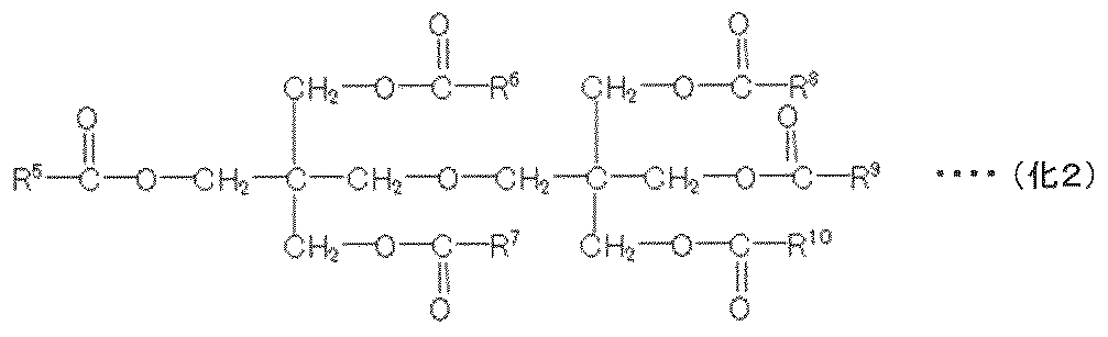
上記特性を有する冷凍機油としては、化学式(化1)、(化2)で表わされるポリオールエステル油、化学式(化3)で表されるポリビニルエーテル油が例示される。式(化1)、(化2)中、R1~R10は、炭素数4~9のアルキル基を表し、それぞれ同一であっても異なってもよい。また、式(化3)中、OR11は、メチルオキシ基、エチルオキシ基、プロピルオキシ基又はブチルオキシ基であり、nは、5~15である。


なお、本発明は上記した実施例に限定されるものではなく、様々な変形例が含まれる。
例えば、上述した本実施例では、密閉型電動圧縮機として、密閉型スクロール圧縮機を採用した例について説明したが、これ以外に、密閉型のロータリー圧縮機やスイングタイプ或いはレシプロタイプの圧縮機を使用するようにしても良い。また、縦型の密閉型電動圧縮機について説明したが、横型のものにも同様に適用できる。
例えば、上述した本実施例では、密閉型電動圧縮機として、密閉型スクロール圧縮機を採用した例について説明したが、これ以外に、密閉型のロータリー圧縮機やスイングタイプ或いはレシプロタイプの圧縮機を使用するようにしても良い。また、縦型の密閉型電動圧縮機について説明したが、横型のものにも同様に適用できる。
また、上記した実施例は本発明で分かりやすく説明するために詳細に説明したものであり、必ずしも説明した全ての構成を備えるものに限定されるものではない。
1:密閉容器、1a:筒部、1b:蓋部、1c:底部、2:圧縮機構部、3:固定スクロール、4:旋回スクロール、4a:旋回軸受、4b:ボス部、5:フレーム、5a:筒部、5b:主軸受、6:回転軸、6a:偏心ピン部、6b:貫通穴、7:電動機、7a:回転子、7b:固定子、8:冷凍機油、9:油溜り部、10:オルダムリング、11:吸込パイプ、12:吸込口、14:吐出口、15:副軸受、16:バランスウェイト、16a:上バランスウェイト、16b:下バランスウェイト、17:エンドコイル、18a,18b:吐出ガス通路、22:吐出パイプ、23:固定子鉄心、23a:中央穴、24:コイル、25:回転子鉄心、26:インシュレータ、27:固定子鉄心の環状部、28:ティース部、30:インシュレータの胴部、32:絶縁フィルム、32a,32b:フィルム、32aa:折り返し部、33:スロット、34:リード線、35:ハーメ端子、36:結束部材、37:リード線接続部用絶縁材、40:吐出室、41:支持部材、50:密閉型電動圧縮機(圧縮機)、51:吐出側冷媒配管、52:油分離器、53:油戻し配管、54:四方切換弁、55:送風機、56:室外側熱交換器、57,59:電子膨張弁(膨張弁)、58:レシーバ、60:送風機、61:室内側熱交換器、62:吸入側冷媒配管、63:アキュームレータ、100:冷凍空調装置(空気調和機)。
Claims (8)
- 密閉容器内に、冷媒を圧縮する圧縮機構部と、前記圧縮機構部を駆動する電動機とを備える高圧チャンバタイプの密閉型電動圧縮機において、
前記電動機は固定子と回転子を備え、前記固定子に使用される樹脂製絶縁材として、ポリエチレンテレフタラート(PET)またはポリエチレンナフタレート(PEN)の素材を使用し、
前記冷媒は、トリフルオロヨードメタン(CF3I)単体、若しくは、前記トリフルオロヨードメタン(CF3I)を含む混合冷媒である
ことを特徴とする密閉型電動圧縮機。 - 請求項1に記載の密閉型電動圧縮機おいて、
前記混合冷媒は、トリフルオロヨードメタン(CF3I)と、ジフルオロメタン(HFC32)と、ペンタフルオロエタン(HFC125)と、を含むことを特徴とする密閉型電動圧縮機。 - 請求項2に記載の密閉型電動圧縮機おいて、
前記混合冷媒は、トリフルオロヨードメタン(CF3I)を30~50wt%含み、ジフルオロメタン(HFC32)を40~60wt%含むことを特徴とする密閉型電動圧縮機。 - 請求項2に記載の密閉型電動圧縮機において、
前記混合冷媒は、トリフルオロヨードメタン(CF3I)とジフルオロメタン(HFC32)を合せて85~95wt%含むことを特徴とする密閉型電動圧縮機。 - 請求項1に記載の密閉型電動圧縮機において、
前記密閉型電動圧縮機は、冷凍機油として、ポリオールエステル(POE)油またはポリビニルエーテル(PVE)油を使用することを特徴とする密閉型電動圧縮機。 - 請求項1に記載の密閉型電動圧縮機において、
前記電動機の固定子は、コイルが巻回されるティース部と、前記ティース部間に設けられ前記コイルが配置されるスロットを備え、前記スロットには前記樹脂製絶縁材としての絶縁フィルムが挿入配置され、前記コイルはこの絶縁フィルムを介して前記ティース部に巻回されていることを特徴とする密閉型電動圧縮機。 - 請求項6に記載の密閉型電動圧縮機において、
前記絶縁フィルムには、140℃での高圧スチームの雰囲気で伸度保持率を50%に保持できる時間が7.5時間以上となるポリエチレンテレフタラート(PET)が使用されていることを特徴とする密閉型電動圧縮機。 - 密閉型電動圧縮機、室外側熱交換器、膨張弁、室内側熱交換器が順次冷媒配管により接続されて冷凍サイクルを構成している冷凍空調装置において、
前記冷凍サイクルを循環する冷媒としてトリフルオロヨードメタン(CF3I)単体、若しくは、前記トリフルオロヨードメタン(CF3I)を含む混合冷媒が封入され、
前記密閉型電動圧縮機として請求項1に記載の密閉型電動圧縮機を使用していることを特徴とする冷凍空調装置。
Priority Applications (1)
| Application Number | Priority Date | Filing Date | Title |
|---|---|---|---|
| JP2020505296A JP6914419B2 (ja) | 2018-08-09 | 2019-07-31 | 密閉型電動圧縮機及びこれを用いた冷凍空調装置 |
Applications Claiming Priority (2)
| Application Number | Priority Date | Filing Date | Title |
|---|---|---|---|
| JP2018-150447 | 2018-08-09 | ||
| JP2018150447 | 2018-08-09 |
Publications (1)
| Publication Number | Publication Date |
|---|---|
| WO2020031801A1 true WO2020031801A1 (ja) | 2020-02-13 |
Family
ID=69414206
Family Applications (1)
| Application Number | Title | Priority Date | Filing Date |
|---|---|---|---|
| PCT/JP2019/029976 Ceased WO2020031801A1 (ja) | 2018-08-09 | 2019-07-31 | 密閉型電動圧縮機及びこれを用いた冷凍空調装置 |
Country Status (2)
| Country | Link |
|---|---|
| JP (1) | JP6914419B2 (ja) |
| WO (1) | WO2020031801A1 (ja) |
Cited By (2)
| Publication number | Priority date | Publication date | Assignee | Title |
|---|---|---|---|---|
| FR3107280A1 (fr) * | 2020-02-19 | 2021-08-20 | Arkema France | Composition comprenant un composé iodofluorocarbure |
| JPWO2022224421A1 (ja) * | 2021-04-23 | 2022-10-27 |
Citations (5)
| Publication number | Priority date | Publication date | Assignee | Title |
|---|---|---|---|---|
| JPH1081600A (ja) * | 1995-09-28 | 1998-03-31 | Mitsui Petrochem Ind Ltd | ドライプロセス用ガス |
| JP2007002115A (ja) * | 2005-06-24 | 2007-01-11 | Toray Ind Inc | ポリマー組成物および二軸延伸フィルム |
| JP2010007857A (ja) * | 2009-08-20 | 2010-01-14 | Hitachi Appliances Inc | 冷媒圧縮機 |
| JP2011502207A (ja) * | 2007-10-31 | 2011-01-20 | イー・アイ・デュポン・ドウ・ヌムール・アンド・カンパニー | ヨードトリフルオロメタンを含む組成物およびそれらの使用 |
| JP2015076953A (ja) * | 2013-10-08 | 2015-04-20 | 日立アプライアンス株式会社 | 密閉型電動圧縮機及び空気調和装置 |
-
2019
- 2019-07-31 WO PCT/JP2019/029976 patent/WO2020031801A1/ja not_active Ceased
- 2019-07-31 JP JP2020505296A patent/JP6914419B2/ja active Active
Patent Citations (5)
| Publication number | Priority date | Publication date | Assignee | Title |
|---|---|---|---|---|
| JPH1081600A (ja) * | 1995-09-28 | 1998-03-31 | Mitsui Petrochem Ind Ltd | ドライプロセス用ガス |
| JP2007002115A (ja) * | 2005-06-24 | 2007-01-11 | Toray Ind Inc | ポリマー組成物および二軸延伸フィルム |
| JP2011502207A (ja) * | 2007-10-31 | 2011-01-20 | イー・アイ・デュポン・ドウ・ヌムール・アンド・カンパニー | ヨードトリフルオロメタンを含む組成物およびそれらの使用 |
| JP2010007857A (ja) * | 2009-08-20 | 2010-01-14 | Hitachi Appliances Inc | 冷媒圧縮機 |
| JP2015076953A (ja) * | 2013-10-08 | 2015-04-20 | 日立アプライアンス株式会社 | 密閉型電動圧縮機及び空気調和装置 |
Cited By (6)
| Publication number | Priority date | Publication date | Assignee | Title |
|---|---|---|---|---|
| FR3107280A1 (fr) * | 2020-02-19 | 2021-08-20 | Arkema France | Composition comprenant un composé iodofluorocarbure |
| WO2021165618A1 (fr) * | 2020-02-19 | 2021-08-26 | Arkema France | Composition comprenant un compose iodofluorocarbure |
| CN115443175A (zh) * | 2020-02-19 | 2022-12-06 | 阿科玛法国公司 | 包含碘氟碳化合物的组合物 |
| JPWO2022224421A1 (ja) * | 2021-04-23 | 2022-10-27 | ||
| WO2022224421A1 (ja) * | 2021-04-23 | 2022-10-27 | 三菱電機株式会社 | 冷凍サイクル装置、圧縮機、モータ、固定子および固定子の製造方法 |
| JP7460017B2 (ja) | 2021-04-23 | 2024-04-02 | 三菱電機株式会社 | 冷凍サイクル装置、圧縮機、モータ、固定子および固定子の製造方法 |
Also Published As
| Publication number | Publication date |
|---|---|
| JP6914419B2 (ja) | 2021-08-04 |
| JPWO2020031801A1 (ja) | 2020-08-20 |
Similar Documents
| Publication | Publication Date | Title |
|---|---|---|
| US10418876B2 (en) | Compressor and heat cycle system for refrigerator | |
| KR101892880B1 (ko) | 냉동 사이클 장치 | |
| JP2009228476A (ja) | スクロール圧縮機 | |
| US20180331436A1 (en) | Refrigeration cycle device | |
| JP6775542B2 (ja) | 冷凍サイクル装置 | |
| JP6450896B1 (ja) | 冷媒組成物及びこれを用いた冷凍サイクル装置 | |
| JP6914419B2 (ja) | 密閉型電動圧縮機及びこれを用いた冷凍空調装置 | |
| WO2016059697A1 (ja) | 冷凍サイクル装置 | |
| US10167438B2 (en) | Compressor for refrigeration and air conditioning, and refrigeration and air conditioning device | |
| CN104518598A (zh) | 密闭型电动压缩机及空调装置 | |
| WO2020050020A1 (ja) | 電動圧縮機及びこれを用いた冷凍空調装置 | |
| WO2020049844A1 (ja) | 圧縮機、及び、これを備える冷凍サイクル装置 | |
| WO2015093183A1 (ja) | 空調装置 | |
| CN105473953A (zh) | 压缩机和制冷循环装置 | |
| JP2009228471A (ja) | スクロール圧縮機 | |
| JP6708288B2 (ja) | 冷凍サイクル装置 | |
| WO2020050022A1 (ja) | 電動圧縮機及びこれを用いた冷凍空調装置 | |
| JP7460017B2 (ja) | 冷凍サイクル装置、圧縮機、モータ、固定子および固定子の製造方法 | |
| JP2020070942A (ja) | 冷凍サイクル装置 | |
| JP2009228470A (ja) | スクロール圧縮機 | |
| WO2023210271A1 (ja) | 冷凍サイクルシステム用の圧縮機 | |
| JP2008121484A (ja) | 冷媒圧縮機 | |
| JP2009228473A (ja) | スクロール圧縮機 | |
| JPH07208338A (ja) | 密閉形コンプレッサおよびこのコンプレッサを用いた冷凍サイクル |
Legal Events
| Date | Code | Title | Description |
|---|---|---|---|
| ENP | Entry into the national phase |
Ref document number: 2020505296 Country of ref document: JP Kind code of ref document: A |
|
| 121 | Ep: the epo has been informed by wipo that ep was designated in this application |
Ref document number: 19847026 Country of ref document: EP Kind code of ref document: A1 |
|
| NENP | Non-entry into the national phase |
Ref country code: DE |
|
| 122 | Ep: pct application non-entry in european phase |
Ref document number: 19847026 Country of ref document: EP Kind code of ref document: A1 |