WO2020031769A1 - 結束機 - Google Patents
結束機 Download PDFInfo
- Publication number
- WO2020031769A1 WO2020031769A1 PCT/JP2019/029616 JP2019029616W WO2020031769A1 WO 2020031769 A1 WO2020031769 A1 WO 2020031769A1 JP 2019029616 W JP2019029616 W JP 2019029616W WO 2020031769 A1 WO2020031769 A1 WO 2020031769A1
- Authority
- WO
- WIPO (PCT)
- Prior art keywords
- binding
- driver
- motor
- processing unit
- error
- Prior art date
- Legal status (The legal status is an assumption and is not a legal conclusion. Google has not performed a legal analysis and makes no representation as to the accuracy of the status listed.)
- Ceased
Links
Images








Classifications
-
- B—PERFORMING OPERATIONS; TRANSPORTING
- B65—CONVEYING; PACKING; STORING; HANDLING THIN OR FILAMENTARY MATERIAL
- B65B—MACHINES, APPARATUS OR DEVICES FOR, OR METHODS OF, PACKAGING ARTICLES OR MATERIALS; UNPACKING
- B65B13/00—Bundling articles
- B65B13/02—Applying and securing binding material around articles or groups of articles, e.g. using strings, wires, strips, bands or tapes
- B65B13/04—Applying and securing binding material around articles or groups of articles, e.g. using strings, wires, strips, bands or tapes with means for guiding the binding material around the articles prior to severing from supply
- B65B13/06—Stationary ducts or channels
-
- B—PERFORMING OPERATIONS; TRANSPORTING
- B65—CONVEYING; PACKING; STORING; HANDLING THIN OR FILAMENTARY MATERIAL
- B65B—MACHINES, APPARATUS OR DEVICES FOR, OR METHODS OF, PACKAGING ARTICLES OR MATERIALS; UNPACKING
- B65B13/00—Bundling articles
- B65B13/18—Details of, or auxiliary devices used in, bundling machines or bundling tools
-
- B—PERFORMING OPERATIONS; TRANSPORTING
- B65—CONVEYING; PACKING; STORING; HANDLING THIN OR FILAMENTARY MATERIAL
- B65B—MACHINES, APPARATUS OR DEVICES FOR, OR METHODS OF, PACKAGING ARTICLES OR MATERIALS; UNPACKING
- B65B13/00—Bundling articles
- B65B13/18—Details of, or auxiliary devices used in, bundling machines or bundling tools
- B65B13/24—Securing ends of binding material
- B65B13/34—Securing ends of binding material by applying separate securing members, e.g. deformable clips
-
- B—PERFORMING OPERATIONS; TRANSPORTING
- B65—CONVEYING; PACKING; STORING; HANDLING THIN OR FILAMENTARY MATERIAL
- B65B—MACHINES, APPARATUS OR DEVICES FOR, OR METHODS OF, PACKAGING ARTICLES OR MATERIALS; UNPACKING
- B65B51/00—Devices for, or methods of, sealing or securing package folds or closures; Devices for gathering or twisting wrappers, or necks of bags
- B65B51/04—Applying separate sealing or securing members, e.g. clips
Definitions
- the present invention relates to a binding machine that can be used for binding a harness, binding a bag mouth, binding a field line or an attraction string, and the like.
- the work of binding and assembling a plurality of harnesses used for power supply and signal communication is performed.
- the method of binding such a harness by manually winding an adhesive tape is mainstream, and workability is poor.
- the binding can be performed mechanically, so that the work of winding the tape can be omitted.
- the present invention has been made in order to solve the above-described problem, and is a binding machine that drives a plastically deformable binding tool having a pair of legs to bind an object to be bound, and a driver that drives the binding tool.
- the present invention is as described above, and is a binding machine that binds an object to be bound by driving a plastically deformable binding tool having a pair of legs, and estimates a driver that drives the binding tool and a load acting on the driver. And an abnormality processing unit that detects a binding error.
- a binding machine that binds an object to be bound by driving a plastically deformable binding tool having a pair of legs, and estimates a driver that drives the binding tool and a load acting on the driver.
- an abnormality processing unit that detects a binding error.
- the abnormality processing unit may estimate the load acting on the driver by referring to the current value flowing through the motor that drives the driver.
- the load acting on the driver increases, the value of the current flowing through the motor increases. Therefore, the load acting on the driver can be estimated with reference to the value of the current flowing through the motor. According to such a configuration, the load acting on the driver can be easily estimated only by checking the value of the current flowing through the motor.
- the abnormality processing unit may detect a binding error based on whether or not the peak value of the current flowing through the motor has reached a predetermined value. Normally, the current value reaches a peak when the binding is completed (when the clinching of the binding device is completed). Therefore, a binding error can be detected by referring to the current value at the time of completing the binding. That is, if the peak value of the current flowing through the motor has not reached the predetermined value, a sufficient fastening strength has not been obtained, so that a binding error can be detected.
- the abnormality processing unit may detect a binding error when the timing at which the current value flowing through the motor starts to rise is out of a predetermined range (when the timing is too early or too late). Good. Normally, the timing at which the current value starts to rise is the timing of the clinch start.If the current value starts to rise at a timing earlier than the clinch start, the driver does not slide smoothly and the object to be bound is thick. It is possible to detect that some problem such as too much has occurred. In addition, if the timing at which the current value starts to rise is too late (when the current value does not start to rise even at the normal clinch start timing), a problem such as the binding device is not set correctly has occurred. Can be detected.
- the abnormality processing unit detects a binding error when the timing at which the current value flowing through the motor reaches a peak is out of a predetermined range (when the timing is too early or too late). Is also good.
- the timing when the current value reaches the peak is usually the timing at which the clinch ends.
- the clinch end timing for example, if the clinch end timing is earlier or later than usual, some problems such as the object to be bound being too thick or the clinch not operating correctly, etc. This can be detected.
- the abnormality processing unit may estimate the load acting on the driver with reference to the pulse for rotating the motor.
- the load acting on the driver increases, the rotation speed of the motor decreases, and the pulse period increases. According to such a configuration, it is possible to easily estimate the load acting on the driver using the pulse signal for rotating the motor.
- the abnormality processing unit may estimate the load acting on the driver with reference to the detection result of the driver or the load sensor provided on the clincher. According to such a configuration, the load acting on the driver can be estimated by directly measuring the load.
- a history management unit that stores a history of binding errors detected by the abnormality processing unit may be provided. According to such a configuration, the presence or absence of a binding error can be confirmed later. For example, when a binding failure is found after shipment, it is possible to later confirm whether the cause of the binding failure is during the binding operation or after the binding operation. Also, by checking the frequency of occurrence of binding errors, it is possible to determine the skill level of the worker, which can be useful for work guidance.
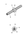
- (A) is a plan view of the binding machine before setting the binding tool, and (b) is a partially enlarged cross-sectional view of the vicinity of the tip of the binding machine in the above a.
- (A) is a plan view of the binding machine after setting the binding tool, and (b) is a partially enlarged cross-sectional view near the tip of the binding machine in the above a.
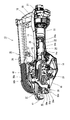
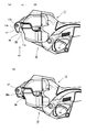
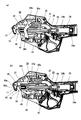
- It is a figure which shows the inside of the binding machine in a standby state, (a) The figure which does not omit the guide member, (b) The figure which omitted some guide members. It is a figure which shows the inside of the binding machine in the middle of binding, (a) The figure which does not omit a guide member, (b) The figure which omitted some guide members.
- FIG. 7A is a graph showing a current waveform flowing through a motor, wherein FIG. 7A is a graph when there is no binding object, FIG. 7B is a graph when normal binding is performed, and FIG. It is a figure explaining a mode that clinch fails, and is a figure before (a) clinch and a figure after (b) clinch. It is an external view of the binding machine concerning a modification.
- front means the direction in which the tying tool 41 is driven
- rear means the direction opposite to the direction in which the tying tool 41 is driven.
- the binding machine 10 is a hand-held binding machine 10 that binds the binding object 50 with the plastically deformable binding tool 41. More specifically, the binding machine 10 can use a binding tool 41 having an opening 41c as shown in FIG. 3A, and closes the binding 41 by closing the opening 41c of the binding tool 41. The object 50 is bound.
- the binding machine 10 is used, for example, for binding a harness, binding a bag mouth, binding a field line or an attraction string, and the like.
- the binding machine 10 is covered by a housing 11 and includes a motor housing 12, a grip 13, and an output unit 15.
- these portions are continuously provided back and forth along the launching direction D2 of the binding tool 41 (see FIG. 6A). That is, when viewed in the launching direction D2 of the binding tool 41, the motor housing 12, the grip 13, and the output unit 15 are arranged in this order from rear to front.
- the motor accommodating section 12 is provided at the rear of the binding machine 10, and a power connection section 12a for connecting an external power supply is provided at the rear end.
- the binding machine 10 can execute various operations such as the ejection of the binding tool 41.
- a cord for connecting to an AC [0] power supply may be connected to the power supply connection portion 12a, or a harness for connecting to a rechargeable battery may be attached to the power supply connection portion 12a.
- the binding machine 10 according to the present embodiment is of an electric type, but is not limited thereto, and the binding machine 10 may be of a compressed air type. In the case of the compressed air type binding machine 10, a connection portion for receiving supply of compressed air may be provided instead of the power supply connection portion 12a.
- the motor housing 12 includes a motor 20 and a controller 21 as shown in FIG.
- the motor 20 is a power source for driving a driving mechanism 22 described later.
- the control unit 21 is a control device that controls the rotation of the motor 20 and the like. In the present embodiment, the control unit 21 is a control board on which a CPU and a memory are mounted.
- the grip 13 is a part that the user grips when using the binding machine 10.
- the grip portion 13 is provided at an intermediate portion of the housing 11, and is formed in a constricted shape so that a user can easily grip the grip portion.
- a trigger 14 is provided diagonally forward of the grip 13 at a position where the trigger 14 can be operated with the index finger when the grip 13 is gripped.
- the trigger 14 is manually operable to execute a binding operation, and in the present embodiment, is a trigger-like swinging member.
- the switch 14a (see FIG. 5) disposed adjacent to the trigger 14 is turned on, and an operation signal is output from the switch 14a to the control unit 21. I have.
- the control unit 21 that has received the operation signal executes an operation of rotating the motor 20 to strike out the binding tool 41. Specifically, when the trigger 14 is operated, a series of cycles including the advance of the driver 25 to the binding position, the holding of the driver 25 at the binding position, and the retreat of the driver 25 to the standby position are performed. It is run continuously.
- the drive mechanism 22 is built in the grip 13 as shown in FIG.
- the drive mechanism 22 is a mechanism that is operated by the motor 20 when the trigger 14 is operated, and performs a bundling operation by reciprocating a driver 25 described later back and forth.
- the drive mechanism 22 includes a speed reduction mechanism 23 and a ball screw 24.
- the reduction mechanism 23 is connected to the rotation shaft of the motor 20 and is a mechanism for reducing the rotation of the motor 20 to obtain a large torque.
- the ball screw 24 is connected to the output shaft of the speed reduction mechanism 23.
- the ball screw 24 rotates the screw shaft 24a by the rotational force of the motor 20, and causes the nut 24b to linearly move back and forth by rotating the screw shaft 24a. Things. Specifically, when the motor 20 rotates forward, the nut 24b moves forward to execute the binding operation. When the motor 20 rotates in the reverse direction after the binding operation is completed, the nut 24b moves rearward and returns to the standby state.
- the size of the machine is reduced, and the machine is easy to handle. Moreover, since the rotating shaft of the motor 20 and the screw shaft 24a of the ball screw 24 are linearly arranged, the machine is slimmed down, and is configured to be easily used even in a narrow work place.
- the output unit 15 is provided near the tip of the binding machine 10. At the tip of the output portion 15, a projecting portion 17 projects in a substantially L-shape, and an insertion opening 16 for inserting the binding object 50 is opened inside the projecting portion 17. As shown in FIG. 5, the output unit 15 includes a driver 25, a guide member 30, and an interlocking mechanism 26. A magazine 35 is provided on the side of the output unit 15, as shown in FIGS.
- the protrusion forming portion 17 is formed as a part of the housing 11 or is integrally fixed to the housing 11.
- a clincher 18 is provided on the inner surface of the protruding portion 17 at a position for receiving a tip of a driver 25 described later. Before the clincher 18 and the driver 25 strike the binding device 41, they stand by at positions separated from each other, and the insertion port 16 is provided between them.
- the binding machine 10 according to the present embodiment performs binding by punching out the binding tool 41 toward the insertion opening 16.
- the insertion port 16 is opened in a direction different from the tip direction of the output unit 15 (the front-back direction of the binding machine 10).
- the opening is opened laterally so as to be substantially orthogonal to the front-back direction.
- the clincher 18 is for clinching the leg 41a of the binding tool 41 that has been driven out by the driver 25 to complete the binding. Specifically, the clincher 18 is a plate against which the binding tool 41 punched out by the driver 25 is pressed. A groove for guiding the leg 41a of the binding tool 41 is formed on the surface of the clincher 18, and the leg 41a of the binding tool 41 pressed against the clincher 18 is bent inward along this groove. Deformed (clinched).
- the projection forming portion 17 provided with the clincher 18 is formed without a movable portion including the clincher 18, and has a simple and slim shape. For this reason, the protrusion forming portion 17 is easily inserted into the gap of the binding object 50 such as a harness.
- the protruding portion 17 has a tapered shape as shown in FIG. Specifically, the outer side surface 17a of the protrusion forming portion 17 is inclined with respect to the opening direction D1 of the insertion port 16, and forms an acute angle with the inner side surface 17b where the clincher 18 is formed. As described above, the protrusion forming portion 17 is tapered in the opening direction D ⁇ b> 1 of the insertion port 16, and has a shape that can be easily inserted into a narrow gap.
- the housing 11 facing the clincher 18 has a pick-up surface 11a.
- the pick-up surface 11a is inclined with respect to the inner side surface 17b of the protrusion forming portion 17 on which the clincher 18 is formed, so that the insertion port 16 is largely opened.
- the binding object 50 such as a harness is easily guided to the inside of the insertion slot 16.
- the pick-up surface 11a covers a guide member 30 (described later) which is on standby before the operation, and when the object 50 to be bound is guided to the inside of the insertion slot 16, the object 50 to be bound is guided by the guide member. 30 is prevented from getting stuck.
- the driver 25 is an elongated plate that performs a linear motion by the drive mechanism 22 in order to drive the binding tool 41 toward the insertion slot 16.
- the driver 25 is slidably guided inside the housing 11 and is capable of reciprocating in the ejection direction D2 of the binding tool 41.
- the driver 25 according to the present embodiment is fixed to a nut 24b of the ball screw 24, and projects forward of the nut 24b. For this reason, when the nut 24b advances, the binding tool 41 is driven out.
- the driver 25 presses the launched binding tool 41 against the clincher 18 to bend the leg 41a of the binding tool 41, thereby closing the opening 41c to complete the binding.
- the guide member 30 is used to stabilize the position of the binding object 50 inserted into the insertion opening 16, and the guide member 30 is inserted immediately before the binding tool 41 is driven out by the driver 25 and the opening 41 c of the binding tool 41 is closed.
- the opening of the mouth 16 is configured to be closed.
- the guide member 30 is attached to the housing 11 so as to be able to swing back and forth about a swing shaft 30a. In a natural state, the guide member 30 is urged by an urging means (not shown) in a direction to open the insertion slot 16.
- the guide member 30 includes an operating pin 30b that engages with a slide member 27 described later.
- the operation pin 30b is slidably engaged with the slide member 27.
- the guide member 30 is inserted against the urging force of the urging means. It is configured to swing in a direction to close the mouth 16.
- the guide member 30 has a claw-shaped tip portion 30c for closing the insertion slot 16.
- a first guide portion 30d and a second guide portion 30e are provided at the distal end portion 30c.
- the first guide portion 30d is for guiding the tying tool 41 when the opening of the insertion opening 16 is closed, and in the state where the insertion opening 16 is closed as shown in FIG. It is formed so as to be parallel to D2. Inside the first guide portion 30d, a groove for guiding the side portion of the binding tool 41 is formed.
- the second guide portion 30e is for holding the object 50 to be bound, and is formed so as to enter the inside of the insertion slot 16 more than the first guide portion 30d when the opening of the insertion slot 16 is closed. I have.
- the interlocking mechanism 26 is a mechanism for operating the guide member 30 in conjunction with the driving operation of the binding tool 41. By operating the guide member 30 via the interlocking mechanism 26, the guide member 30 is configured to operate in synchronization with the ejection operation of the binding tool 41.
- the interlocking mechanism 26 includes a slide member 27 and a connection member 28 as shown in FIG. The slide member 27 is fixed to a nut 24b of the ball screw 24 by a connection member 28, and is configured to move back and forth integrally with the nut 24b.
- the slide member 27 is configured to engage with the operating pin 30b of the guide member 30, as shown in FIGS. 9B, 10B, and 11B. Specifically, a continuous engaging surface is formed by the hook 27a, the inclined portion 27b, and the horizontal portion 27c, and the engaging surface engages with the operating pin 30b.
- the hook 27a forms a substantially U-shaped groove, and is a portion that engages with the operating pin 30b in a standby state (a state before the binding tool 41 is launched).
- the inclined portion 27b is a surface that is inclined with respect to the launching direction D2 of the binder 41.
- the guide member 30 swings when the operation pin 30b slides on the inclined portion 27b.
- the horizontal portion 27c is a surface parallel to the launching direction D2 of the tying tool 41.
- the guide member 30 is moved to the opening of the insertion slot 16. Is kept closed.
- the magazine 35 is for mounting a plurality of binding tools 41.
- the tying device 10 uses a tying device 40 as shown in FIG. 3, and such a tying device 40 can be attached to the magazine 35.
- connection tying tool 40 is configured by connecting a plurality of tying tools 41 to each other.
- Each tying member 41 is a member made of resin such as plastic, and includes a pair of legs 41a and a connecting portion 41b connecting the pair of legs 41a, and is formed in a substantially U-shape.
- An opening 41c for holding the object 50 to be bound is formed between the pair of legs 41a.
- the magazine 35 has a rib 35a that enters between the legs 41a of the tying member 41 (that is, the opening 41c).
- a groove 35b for guiding the connecting portion 41b of the binding tool 41 is formed so as to face the tip of the rib 35a.
- the magazine 35 is provided with a pusher 36 that can slide along the longitudinal direction of the magazine 35.
- the pusher 36 is for urging the connecting tying device 40 mounted on the magazine 35 forward, and is always urged forward (in a direction in which the tying device 41 is fed into the standby unit 37 described later) by a spring (not shown). Have been.
- This magazine 35 is connected to the side of the output unit 15 and is configured to guide the connecting and binding device 40 inside the output unit 15.
- a standby section 37 is provided inside the output section 15 that is continuous with the magazine section 35 so as to allow the binding tool 41 to stand by in a state where it can be punched out.
- the standby section 37 is provided between the driver 25 and the insertion slot 16, and the binding tool 41 waiting in the standby section 37 is driven out by the driver 25 in the direction of the insertion slot 16.
- the opening 41c of the binding tool 41 waiting at the standby section 37 is open toward the launch direction D2 of the binding tool 41, that is, toward the distal end of the output unit 15.
- the insertion port 16 is opened in a direction substantially orthogonal to the tip direction of the output unit 15. For this reason, in the present embodiment, the opening direction of the insertion port 16 and the opening direction of the binding tool 41 closed by the driver 25 are set to different directions.
- the connecting tying tool 40 when attaching the connecting tying tool 40 to the magazine 35, the connecting tying tool 40 is attached so as to straddle the rib 35a, and the groove 35b of the magazine 35 is connected to the tying tool 41.
- the part 41b passes.
- the connecting tying member 40 is mounted in this manner, the connecting tying member 40 is urged by the pusher 36 in the direction of the standby portion 37.
- the binding tool 41 can be driven out only by setting the connection binding tool 40. According to such a configuration, the operation of sending the binding tool 41 to the binding position before launching is unnecessary.
- the connecting tying tool 40 is urged in the direction of the standby unit 37 by the pusher 36, but the invention is not limited thereto, and the tying tool 41 is moved to the standby unit 37 in conjunction with the driving of the driver 25.
- a feeding mechanism may be provided.
- the binding object 50 is inserted into the insertion opening 16.
- the opening direction D1 of the insertion port 16 is set to a direction different from the ejection direction D2 of the tying tool 41 (that is, the advancing / retreating direction of the driver 25), so that the tying object 50 is hooked. In this way, the object 50 to be bound can be engaged with the inside of the insertion slot 16.
- the motor 20 rotates and the drive mechanism 22 operates.
- the guide member 30 is operated by the drive mechanism 22.
- the operating pin 30b is engaged with the hook 27a of the slide member 27, and the guide member 30 opens the opening of the insertion slot 16. It is in a state of being left.
- the drive mechanism 22 starts operating from this state, as shown in FIG. 10, the slide member 27 moves forward, so that the operation pin 30b moves along the inclined portion 27b of the slide member 27. 30 swings to close the opening of the insertion slot 16.
- the guide member 30 is in a state in which the opening of the insertion port 16 is completely closed.
- the driver 25 drives out the tying tool 41 supplied to the standby unit 37, and the leg 41a of the tying out the tying tool 41 is moved.
- the clinching is completed by the clincher 18 (see FIG. 11).
- the motor 20 rotates in the reverse direction and returns to the standby state as shown in FIG.
- the driver 25 retreats from the standby unit 37, so that the standby unit 37 is vacant. Therefore, the pusher 36 pushes the connecting tying tool 40 in the magazine 35, and the next tying tool 41 is automatically turned on. Sent to.
- the guide member 30 also swings in the opening direction. The guide member 30 swings to a position where the operation pin 30b is engaged with the hook 27a of the slide member 27, and returns to a state where the opening of the insertion port 16 is opened.
- control unit 21 The binding operation as described above is controlled by the control unit 21. More specifically, the control unit 21 according to the present embodiment is configured such that the CPU reads a program stored in the ROM, thereby controlling various input devices and output devices as shown in FIG.
- the input device for the control unit 21 includes the above-described switch 14a, the current value measurement unit 60, the clog sensor 45, and the guide sensor 46.
- the motor 20 described above and the notification unit 38 are provided. Note that the input device and the output device are not limited to these devices, and may include other input devices and output devices.
- the current value measuring unit 60 is for measuring an output current value supplied to the motor 20.
- the current value measurement unit 60 is configured to always (or at a predetermined cycle) measure the output current value supplied to the motor 20 while the motor 20 is operating, and to transmit the result to the control unit 21. .
- the clogging sensor 45 is a sensor for detecting clogging of the binding tool 41.
- the clog sensor 45 is arranged so as to face the insertion port 16 as shown in FIG. 9B, for example.
- the clog sensor 45 according to the present embodiment includes a detection unit 45a that protrudes from the main body so as to be able to protrude and retract.
- the detection unit 45a is provided so as to protrude into the launching path of the binding tool 41. For this reason, when the tying member 41 is present in the insertion slot 16, the detecting portion 45a is pushed in and the clogging is detected. In the present embodiment, if the state where the detection unit 45a is pushed in continues even after a predetermined time has elapsed after the binding is completed, it is determined that the clogging has occurred.
- a predetermined clogging error process is executed.
- a process of notifying an error to an operator by a notifying unit 38 described later may be executed.
- the next bundling operation may not be performed until the clogging is eliminated.
- the error may be notified by the notifying unit 38.
- the history management unit 130 described later stores the history information of the error, the status of the machine can be grasped using this history information. For example, when a clogging error frequently occurs, it can be determined that the need for maintenance is high. If it is determined that the need for maintenance is high, the notification means 38 may notify the worker.
- the clogging is detected by physically pressing the detection unit 45a of the clogging sensor 45.
- the clogging may be detected by another method.
- a non-contact type sensor may be used as the clog sensor 45.
- the guide sensor 46 is a sensor for detecting a state in which the guide member 30 is completely closed.
- the guide sensor 46 is disposed at a position where the guide sensor 46 overlaps the tip of the guide member 30 when the guide member 30 is closed, as shown in FIGS. 9B, 10A, and 10B, for example.
- the guide sensor 46 according to the present embodiment includes a detection unit 46a protruding from the main body so as to be able to protrude and retract.
- the detection section 46a is provided so as to protrude so as to be able to contact the guide member 30. For this reason, when the guide member 30 is completely closed, the detection section 46a is pushed in, and it is detected that the guide member 30 is closed.
- the binding machine 10 When the guiding sensor 46 detects that the guide member 30 is closed when the binding operation is performed, the binding machine 10 performs the binding operation. That is, the binding tool 41 is driven out by the driver 25, and the binding is performed.
- a predetermined guide error process is performed.
- the guide error process a process of interrupting the binding operation and returning the state of the machine to the state before binding is executed. At this time, the error may be notified to the operator by the notifying means 38 described later.
- a guide sensor 46 it is possible to prevent the binding from being performed in a state where the guide member 30 is not closed. For example, if the binding is performed in a state where the guide member 30 is not closed in order to bind the binding object 50 exceeding the maximum diameter allowed by the machine, a binding error occurs or the binding object 50 is damaged. There is a possibility that. By providing the guide sensor 46, such a problem can be avoided.
- the guide member 30 is detected by physically pressing the detection portion 46a of the guide sensor 46.
- the present invention is not limited to this, and the guide member 30 is detected by another method. May be.
- a non-contact type sensor may be used as the guide sensor 46.
- the notifying unit 38 is for notifying the operator of various information such as the state of the machine.
- the notifying unit 38 notifies a worker of information by generating sound, display, vibration, and the like.
- the binding machine 10 includes an LED as the notification unit 38.
- the notification means 38 is not limited to the LED, and may include a liquid crystal screen as shown in FIG.
- a speaker, a vibration motor, or the like may be provided as the notification unit 38.
- the control unit 21 realizes functions as a drive control unit 110, an abnormality processing unit 120, and a history management unit 130, as shown in FIG. 12, to control the input device and the output device described above.
- the drive control unit 110 controls the binding operation by controlling the drive of the motor 20.
- the drive control unit 110 receives an input signal from the switch 14a, drives the motor 20, and executes a binding process. Further, when the above-described clogging error or guide error occurs, execution of error processing may be controlled.
- the abnormality processing section 120 detects a binding error by estimating the load acting on the driver 25.
- the abnormality processing unit 120 estimates the load acting on the driver 25 with reference to the current value (current value flowing through the motor 20) measured by the current value measurement unit 60.
- the processing of the abnormality processing unit 120 will be specifically described with reference to FIG. 13 illustrating a waveform of a current flowing through the motor 20.
- FIG. 13A shows a current waveform when the binding process is performed in a state where the binding object 50 does not exist.
- a large resistance does not act on the driver 25, and the load acting on the driver 25 is small. The value is kept low.
- the load acting on the driver 25 gradually increases because the deformation resistance of the tying tool 41 is applied.
- the load acting on the driver 25 increases, the value of the current flowing through the motor 20 also gradually increases.
- the load acting on the driver 25 reaches a peak, so that the current flowing through the motor 20 also reaches a peak.
- FIG. 13B shows a current waveform when the binding process is executed in a normal state where the binding object 50 exists.
- a period before the binding tool 41 reaches the clincher 18 a period before B1
- a large resistance does not act on the driver 25 and the load acting on the driver 25 is small, so that the current The value is kept low.
- the load acting on the driver 25 gradually increases because the deformation resistance of the tying tool 41 is applied.
- the load acting on the driver 25 increases, the value of the current flowing through the motor 20 also gradually increases.
- the load acting on the driver 25 reaches a peak, so that the current flowing through the motor 20 also reaches a peak.
- the load acting on the driver 25 is further increased due to the fastening resistance. Therefore, the peak of the current value shown in FIG. 13B is higher than the peak of the current value shown in FIG. In other words, the tighter the binding object 50, the higher the peak of the current value is detected.
- FIG. 13 (c) shows a current waveform when a binding error has occurred. More specifically, as shown in FIG. 14A, the tying tool 41 is slantedly punched with respect to the clincher 18 for some reason, and as shown in FIG. It is a current waveform when the part 41a is not correctly clinched. As shown in FIG. 13C, in a period before the binding device 41 reaches the clincher 18 (a period before C1), a large resistance does not act on the driver 25, and the load acting on the driver 25 is reduced. Since it is small, the current value is kept low.
- the load acting on the driver 25 gradually increases, so that the current value also gradually increases.
- the leg portion 41a of the tying member 41 is not correctly clinched, the deformation resistance of the leg portion 41a does not increase significantly, so that the load acting on the driver 25 does not greatly increase thereafter. That is, the peak of the current value is lower than the examples shown in FIGS. 13A and 13B.
- the abnormality processing unit 120 detects a binding error based on whether or not the peak value of the current flowing through the motor 20 has reached a predetermined value.
- the threshold value P1 shown in FIG. 13 may be used as the predetermined value to be compared with the peak value of the current.
- This threshold value P1 is set based on the load acting on the driver 25 when the leg 41a of the binding tool 41 is correctly clinched.
- the threshold value P1 when the threshold value P1 is used as the predetermined value to be compared with the peak value of the current, as shown in FIGS. 13A and 13B, when the peak value of the current reaches the threshold value P1, Determines that binding has been performed successfully.
- FIG. 13C when the peak value of the current has not reached the threshold value P1, it is determined that a binding error has occurred.
- this threshold value P1 it can be set so that a binding error is not determined even when the binding process is executed in a state where the binding target object 50 does not exist as shown in FIG.
- the threshold value P2 shown in FIG. 13 may be used as a predetermined value to be compared with the peak value of the current.
- This threshold value P2 is set based on a load acting on the driver 25 when the leg 41a of the binding tool 41 is correctly clinched and the binding target 50 is tightened.
- the threshold value P2 is used as the predetermined value to be compared with the peak value of the current, as shown in FIG. 13B, when the peak value of the current has reached the threshold value P2, the binding is normally performed. Judge that it was executed.
- FIGS. 13A and 13C when the peak value of the current has not reached the threshold value P2, it is determined that a binding error has occurred.
- this threshold value P2 is used, a setting can be made such that a binding error is determined when the binding process is executed in a state where the binding object 50 does not exist as shown in FIG.
- a predetermined error process may be executed.
- the notifying unit 38 may notify the worker of the error.
- the machine may be stopped at the timing when a binding error is detected, and may return to the state before binding.
- the abnormality processing unit 120 detects a binding error by referring to the peak of the current value.
- the binding error may be detected by another method.
- a timing at which the current value starts to rise is detected, and this timing deviates from a predetermined range. If it is (the timing is too early or too late), it may be determined that there is a binding error.
- the timing at which the current value starts to rise is usually the timing of the clinch start. Therefore, if the current value starts to rise at a timing earlier than the clinch start, the driver 25 does not slide smoothly, and It is possible to detect that some problem has occurred, such as that the image is too thick.
- the timing at which the current value starts to rise is too late (when the current value does not start to rise even at the normal clinch start timing), some problem such as the binding device 41 not being set correctly has occurred. Can be detected.
- the timing at which the current value starts to increase may be determined, for example, by the time from when the driver 14 starts driving by operating the switch 14a to when the current value starts to increase.
- a timing at which the current value reaches a peak is detected, and when this timing deviates from a predetermined range (the timing is too early). If it is too late or too late), it may be determined that there is a binding error.
- the timing when the current value reaches the peak is usually the timing at which the clinch ends. By referring to the clinch end timing, for example, if the clinch end timing is too early or too late, the object 50 to be bound is too thick or the clinch is not operating properly. Can be detected.
- the timing at which the current value reaches the peak may be determined, for example, by the time from when the switch 14a is operated and the driver 25 starts driving until the current value reaches the peak. Alternatively, the determination may be made based on the time from when the current value reaches a peak after exceeding the threshold value P1. Alternatively, it may be determined based on the time from when the threshold value P1 is exceeded to when the threshold value P2 is reached.
- the history management unit 130 manages the history of the binding work.
- the history management unit 130 can store, for example, a history of binding errors detected by the abnormality processing unit 120.
- the history management unit 130 can store the number of times a mistake has occurred in binding after the machine was reset. Therefore, for example, after performing the binding operation continuously, it is possible to confirm whether or not a binding error has occurred and when the binding error has occurred. By using such a function, the presence or absence of a binding error can be confirmed later. For example, when a binding failure is found after shipment, it is possible to later confirm whether the cause of the binding failure is during the binding operation or after the binding operation. Further, by checking the frequency of occurrence of a binding error, the skill level of the worker can be determined, which can be used for work guidance. Further, even when the binding operation is automatically performed using a robot, the presence or absence of a binding error can be confirmed without visually checking the actual product.
- the history management unit 130 may store the history of the current waveform measured by the current value measurement unit 60. That is, the measurement history of the current value flowing through the motor 20 may be stored not only when a binding error occurs but also when binding is performed normally. In this way, all binding histories can be confirmed later, so that work histories can be left.
- the work history thus left can be used, for example, as proof that the work has been completed without occurrence of a binding error.
- by checking the current waveform left as the work history it is possible to check the degree of tightening of the binding object 50.
- the history management unit 130 may store a history of the number of times of binding. Then, the stored binding times may be displayed to the user. As a method of displaying the number of times of binding to the user, for example, it may be displayed on a liquid crystal screen or the like, or may be output to the outside (for example, a terminal such as a smartphone, a control device, a server, or the like). Good. Further, when the number of times of binding has reached a predetermined number, a notification may be made by the notification means 38 (display, sound, vibration). At this time, the specified number used for the notification may be set freely by the user.
- the specified number is set to “5”, so that every five bindings are performed.
- the notification can be set to be executed.
- the specified number is set to “10”, so that every five bindings are performed.
- the notification can be set to be executed.
- the notification is executed every 10 times. It can be set as follows. Such a setting eliminates the need for the operator to count the number of times of binding, so that errors are less likely to occur and the working efficiency can be increased.
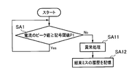
- the abnormality processing unit 120 determines whether or not the peak value of the current flowing through the motor 20 has reached a predetermined value, that is, the peak value of the current measured by the current value measurement unit 60 in step SA1 in FIG. It is determined whether the value is equal to or greater than the threshold value P1. If the peak value of the current is equal to or larger than the threshold value P1, the abnormality processing unit 120 determines that the binding has been performed normally, and returns to the processing of step SA1. On the other hand, if the peak value of the current is smaller than the threshold value P1, the abnormality processing unit 120 determines that binding is not performed normally (a binding error has occurred), and performs abnormality processing in step SA11. Next, in step SA12, the history management unit 130 stores the history of the binding error.
- the abnormality processing unit 120 determines whether or not the peak value of the current flowing through the motor 20 has reached a predetermined value in step SA2 in FIG. 17, that is, the peak value of the current measured by the current value measurement unit 60. It is determined whether the value is equal to or greater than the threshold value P2. If the peak value of the current is equal to or greater than the threshold value P2, the abnormality processing unit 120 determines that the binding has been performed normally, and returns to the processing of step SA2. On the other hand, when the peak value of the current is smaller than the threshold value P2, the abnormality processing unit 120 determines that the binding is not performed normally (a binding error has occurred), and performs an abnormal process in step SA21. Next, in step SA22, the history management unit 130 stores the history of the binding error.
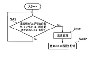
- the abnormality processing unit 120 determines whether or not the timing A1 at which the value of the current flowing through the motor 20 starts to rise deviates from a predetermined range in step SA3 in FIG. If the timing A1 does not deviate from the predetermined range, the abnormality processing unit 120 determines that the binding has been performed normally, and returns to the processing of step SA3. On the other hand, if the timing A1 is out of the predetermined range, the abnormality processing unit 120 determines that the binding is not performed normally (a binding error has occurred), and performs an abnormal process in step SA31. Next, in step SA32, the history management unit 130 stores the history of the binding error.
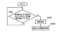
- step SA4 in FIG. 19 the abnormality processing unit 120 determines whether the timing B1 at which the value of the current flowing through the motor 20 starts to rise deviates from a predetermined range. If the timing B1 does not deviate from the predetermined range, the abnormality processing unit 120 determines that the binding has been performed normally, and returns to the processing of step SA4. On the other hand, if the timing B1 is out of the predetermined range, the abnormality processing unit 120 determines that the binding is not performed normally (a binding error has occurred), and performs an abnormal process in step SA41. Next, in step SA42, the history management unit 130 stores the history of the binding error.
- step SA5 in FIG. 20 the abnormality processing unit 120 determines whether or not the timing C1 at which the value of the current flowing through the motor 20 starts to rise deviates from a predetermined range. If the timing C1 does not deviate from the predetermined range, the abnormality processing unit 120 determines that the binding has been performed normally, and returns to the processing of step SA5. On the other hand, if the timing C1 is out of the predetermined range, the abnormality processing unit 120 determines that binding is not performed normally (a binding error has occurred), and performs abnormality processing in step SA51. Next, in step SA52, the history management unit 130 stores the history of the binding error.
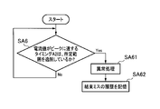
- the abnormality processing unit 120 determines whether or not the timing A2 at which the value of the current flowing through the motor 20 reaches the peak deviates from a predetermined range in step SA6 in FIG. If the timing A2 does not deviate from the predetermined range, the abnormality processing unit 120 determines that the binding has been performed normally, and returns to the processing of step SA6. On the other hand, if the timing A2 is out of the predetermined range, the abnormality processing unit 120 determines that the binding is not performed normally (a binding error has occurred), and performs an abnormal process in step SA61. Next, in step SA62, the history management unit 130 stores the history of the binding error.
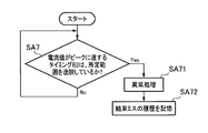
- the abnormality processing unit 120 determines whether or not the timing B2 at which the value of the current flowing through the motor 20 reaches the peak deviates from a predetermined range in step SA7 in FIG. If the timing B2 does not deviate from the predetermined range, the abnormality processing unit 120 determines that the binding has been performed normally, and returns to the processing of step SA7. On the other hand, if the timing B2 is out of the predetermined range, the abnormality processing unit 120 determines that binding is not performed normally (a binding error has occurred), and performs an abnormal process in step SA71. Next, in step SA72, the history management unit 130 stores the history of the binding error.
- the binding machine 10 is a binding machine 10 for driving a plastically deformable binding tool 41 having a pair of legs 41a and binding the object 50 to be bound. It includes a driver 25 that drives to drive the binding tool 41 and an abnormality processing unit 120 that detects a binding error by estimating a load acting on the driver 25. According to such a configuration, by estimating the load acting on the driver 25, it is possible to estimate the deformation resistance of the leg 41 a of the tying tool 41 and the degree of tightening of the tying.
- the binding machine 10 may be attached to a machine such as a robot arm.
- a portion attached to a machine such as a robot arm may be the grip portion 13.
- the binding machine 10 is configured to receive a voltage supply from the power supply connection unit 12a.
- the present invention is not limited to this, and the binding machine 10 may have a built-in power supply.
- the battery pack may be detachable.
- the binding machine 10 according to the above-described embodiment includes the control unit 21, but is not limited thereto, and the control unit 21 may be disposed outside the machine.
- the binding machine 10 may be operated by centralized control or the like.
- the hand-held binding machine 10 has been described.
- the present invention is not limited to this, and the present invention may be applied to a stationary binding machine 10.
- the abnormality processing unit 120 estimates the load acting on the driver 25 with reference to the value of the current flowing through the motor 20, but is not limited thereto.
- the abnormality processing unit 120 may estimate a load acting on the driver 25 with reference to a pulse for rotating the motor 20. That is, if the load acting on the driver 25 increases, the speed of the driver 25 decreases, so that the rotation speed of the motor 20 also decreases and the pulse period increases. Therefore, even when the pulse waveform is referred to, the load acting on the driver 25 can be estimated as in the case where the current waveform illustrated in FIG. 13 is referred to.
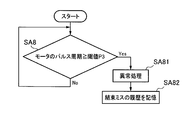
- FIG. 23 shows a processing flow in the binding machine 10 in this case.
- the abnormality processing unit 120 determines whether or not the pulse cycle of the motor 20 is equal to or larger than the threshold value P3 in step SA8.
- the abnormality processing unit 120 determines that the binding has been performed normally, and returns to the processing of step SA8. On the other hand, if the pulse cycle of the motor 20 is equal to or greater than the threshold value P3, the abnormality processing unit 120 determines that binding is not performed normally (a binding error has occurred), and performs abnormality processing in step SA81. Next, in step SA82, the history management unit 130 stores the history of the binding error.
- a load sensor may be provided in the driver 25 or the clincher 18 and the abnormality processing unit 120 may estimate the load acting on the driver 25 with reference to the detection result of the load sensor. According to such a configuration, the load acting on the driver 25 can be directly estimated.
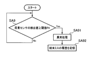
- FIG. 24 shows a processing flow in the binding machine 10 in this case.
- the abnormality processing unit 120 determines whether or not the detected value of the load sensor is equal to or larger than the threshold value P4 in step SA9. If the detection value of the load sensor is not larger than the threshold value P4, the abnormality processing unit 120 determines that the binding has been performed normally, and returns to the processing of step SA9.
- the abnormality processing unit 120 determines that the binding is not performed normally (a binding error has occurred), and performs an abnormal process in step SA91.
- the history management unit 130 stores the history of the binding error.
- the binding error is detected by estimating the load acting on the driver 25, but the binding error can be detected by another method.
- a camera capable of photographing the binding site on the binding machine 10 or the peripheral device, and confirm a binding error or the tightening condition of the binding target 50 from the photographed image.
Landscapes
- Engineering & Computer Science (AREA)
- Mechanical Engineering (AREA)
- Basic Packing Technique (AREA)
Abstract
一対の脚部(41a)を有する塑性変形可能な結束具(41)を打ち込んで被結束物(50)を結束する結束機(10)であって、モータ(20)によって駆動して結束具(41)を打ち出すドライバ(25)と、ドライバ(25)に作用する荷重を推定することにより結束ミスを検出する異常処理部(120)と、を備えるようにした。
Description
この発明は、ハーネスの結束や、袋口の結束、畑の番線や誘引紐の結束などに使用可能な結束機に関する。
例えば家電製品を製造する工場において、電源供給や信号通信に用いられる複数のハーネスを結束して組み付ける作業が行われる。こうしたハーネスの結束は、手作業で粘着テープを巻き付けて行う方法が主流であり、作業性が悪かった。
この点、例えば特許文献1に記載されているような結束機を使用すれば、機械的に結束が行えるため、テープを巻き付ける手間を省くことができる。
しかしながら、結束機を使用して大量に結束を行った場合、結束の締め付け具合や結束ミスの有無などを確認することが困難であった。特に、ロボット制御などにより結束機を無人設備で使用する場合、結束の締め付け具合や結束ミスの有無を結束作業中に目視確認できないため、結束作業後に現物を確認しなければならず、作業性が悪くなるおそれがあった。
そこで、本発明は、目視確認しなくても結束ミスの有無などを確認することができる結束機を提供することを課題とする。
本発明は、上記した課題を解決するためになされたものであり、一対の脚部を有する塑性変形可能な結束具を打ち込んで被結束物を結束する結束機であって、結束具を打ち出すドライバと、前記ドライバによって打ち出された結束具の脚部をクリンチして結束を完了させるためのクリンチャと、前記ドライバに作用する荷重を推定することにより結束ミスを検出する異常処理部と、を備えることを特徴とする。
本発明は上記の通りであり、一対の脚部を有する塑性変形可能な結束具を打ち込んで被結束物を結束する結束機であって、結束具を打ち出すドライバと、ドライバに作用する荷重を推定することにより結束ミスを検出する異常処理部と、を備える。このような構成によれば、ドライバに作用する荷重を推定することで、結束具の脚部の変形抵抗や結束の締め付け具合を推定することができる。例えば、ドライバに作用する荷重が小さすぎる場合には、結束具の脚部が正しくクリンチされていない可能性があるので、結束ミスと判断することができる。このように一対の脚部を有する結束具を打ち込むタイプの結束機の特性を活かして、目視確認しなくても結束ミスを検出することができる。このため、ロボット制御などにより結束機を無人設備で使用する場合であっても、結束作業後に現物を確認する必要がなく、作業性を向上させることができる。
また、異常処理部は、ドライバを駆動するモータに流れる電流値を参照してドライバに作用する荷重を推定するようにしてもよい。ドライバに作用する荷重が大きくなれば、モータに流れる電流値が大きくなるので、モータに流れる電流値を参照してドライバに作用する荷重を推定することができる。このような構成によれば、モータに流れる電流値を確認するだけで、容易にドライバに作用する荷重を推定することができる。
また、異常処理部は、モータに流れる電流のピーク値が予め定められた所定値に到達しているか否かによって結束ミスを検出するようにしてもよい。通常、結束完了時(結束具のクリンチ完了時)に電流値がピークとなるため、この結束完了時の電流値を参照することで結束ミスを検出することができる。すなわち、モータに流れる電流のピーク値が予め定められた所定値に到達していない場合には、十分な締め付け強度が得られていないため、結束ミスと検出することができる。
また、異常処理部は、モータに流れる電流値が上がり始めるタイミングが予め定められた所定範囲を逸脱している場合(タイミングが早すぎるまたは遅すぎる場合)に、結束ミスを検出するようにしてもよい。電流値が上がり始めるタイミングは、通常はクリンチ開始のタイミングであるため、クリンチ開始よりも早いタイミングで電流値が上がり始めた場合には、ドライバがスムーズに摺動していない、被結束物が太すぎる、などの何らかの問題が発生していることを検出することができる。また、電流値が上がり始めるタイミングが遅すぎる場合(通常のクリンチ開始のタイミングでも電流値が上がり始めない場合)には、結束具が正しくセットされていない、などの何らかの問題が発生していることを検出することができる。
また、異常処理部は、モータに流れる電流値がピークに達するタイミングが予め定められた所定範囲を逸脱している場合(タイミングが早すぎるまたは遅すぎる場合)に、結束ミスを検出するようにしてもよい。電流値がピークに達するタイミングは、通常はクリンチ終了のタイミングである。クリンチ終了のタイミングを参照することにより、例えばクリンチ終了のタイミングが通常よりも早すぎたり遅すぎたりする場合には、被結束物が太すぎる、正しくクリンチが作動していない、などの何らかの問題が発生していることを検出することができる。
また、異常処理部は、モータを回転させるためのパルスを参照してドライバに作用する荷重を推定するようにしてもよい。ドライバに作用する荷重が大きくなれば、モータの回転速度が遅くなるため、パルス周期が大きくなる。このような構成によれば、モータを回転させるためのパルス信号を利用して、容易にドライバに作用する荷重を推定することができる。
また、異常処理部は、ドライバまたはクリンチャに設けられた荷重センサの検出結果を参照してドライバに作用する荷重を推定するようにしてもよい。このような構成によれば、直接的に荷重を測定することで、ドライバに作用する荷重を推定することができる。
また、異常処理部が検出した結束ミスの履歴を記憶する履歴管理部を備えていてもよい。このような構成によれば、結束ミスの有無を後から確認することができる。例えば、出荷後に結束不良が判明した場合に、結束不良の原因が結束作業中にあるのか結束作業後にあるのかを後から確認することができる。また、結束ミスの発生頻度を確認することで、作業者の熟練度を判定することができるので、作業指導に役立てることも可能となる。
本発明の実施形態について、図を参照しながら説明する。なお、以下においては、「前」は結束具41が打ち出される方向を意味し、「後」は結束具41が打ち出される方向の反対方向を意味するものとして説明する。
本実施形態に係る結束機10は、塑性変形可能な結束具41によって被結束物50を結束する手持ち式の結束機10である。具体的には、この結束機10は、図3(a)に示すような開口部41cを備えた結束具41を使用可能となっており、結束具41の開口部41cを閉じることによって被結束物50を結束するものである。この結束機10は、例えば、ハーネスの結束や、袋口の結束、畑の番線や誘引紐の結束などに使用される。
この結束機10は、図1に示すように、ハウジング11によって覆われており、モータ収容部12と、グリップ部13と、出力部15と、を備えている。本実施形態に係る結束機10では、これらの部位が結束具41の打ち出し方向D2(図6(a)参照)に沿って前後に連続して設けられている。すなわち、結束具41の打ち出し方向D2に見て、後方から前方へ、モータ収容部12、グリップ部13、出力部15の順に配置されている。
モータ収容部12は、結束機10の後部に設けられており、後端部には外部電源を接続するための電源接続部12aが設けられている。この電源接続部12aから電圧供給を受けることで、結束機10は結束具41の打ち出しなどの各種動作を実行できるようになっている。この電源接続部12aには、交流[0]電源に接続するためのコードが接続されるように構成してもよいし、充電池に繋げるためのハーネスが取り付けられてもよい。なお、本実施形態に係る結束機10は電気式であるが、これに限らず、結束機10は圧縮空気式であってもよい。圧縮空気式の結束機10の場合、電源接続部12aの代わりに、圧縮空気の供給を受けるための接続部を設けてもよい。
このモータ収容部12には、図5に示すように、モータ20や制御部21が内蔵されている。モータ20は、後述する駆動機構22を駆動するための動力源である。また、制御部21は、モータ20の回転などを制御する制御装置であり、本実施形態においてはCPUやメモリを実装した制御基板である。
グリップ部13は、結束機10の使用時に使用者が把持する部位である。このグリップ部13は、ハウジング11の中間部に設けられており、使用者が把持しやすいように、くびれた形状で形成されている。このグリップ部13の斜め前方には、グリップ部13を把持したときに人差し指で操作可能な位置にトリガ14が設けられている。トリガ14は、結束動作を実行するために手動操作可能となっており、本実施形態においては引き金状の揺動部材である。このトリガ14を使用者が引き操作すると、トリガ14に隣接して配置されたスイッチ14a(図5参照)がオンになり、スイッチ14aから制御部21へと操作信号が出力されるようになっている。操作信号を受信した制御部21は、モータ20を回転させて結束具41を打ち出す動作を実行するようになっている。詳しくは、トリガ14が操作されたときに、結束位置までのドライバ25の前進と、結束位置でのドライバ25の保持と、待機位置までのドライバ25の後退と、で構成される一連のサイクルが連続して実行されるようになっている。
このグリップ部13には、図5に示すように、駆動機構22が内蔵されている。駆動機構22は、トリガ14が操作されたときにモータ20によって作動する機構であり、後述するドライバ25を前後に往復動させることで結束動作を行うものである。
この駆動機構22は、減速機構23と、ボールねじ24と、を備えている。減速機構23は、モータ20の回転軸に接続されており、モータ20の回転を減速させて大きなトルクを得られるようにするための機構である。また、ボールねじ24は、減速機構23の出力軸に接続されており、モータ20の回転力によってねじ軸24aを回転させ、ねじ軸24aを回転させることでナット24bを前後に直進運動させるためのものである。具体的には、モータ20が正回転したときには、ナット24bが前方へと移動して結束動作が実行されるように構成されている。また、結束動作の完了後にモータ20が逆回転したときには、ナット24bが後方へと移動して待機状態へと戻るように構成されている。
本実施形態においては、グリップ部13に駆動機構22を内蔵することで、機械が小型化されており、取り回しの良い機械となっている。しかも、モータ20の回転軸とボールねじ24のねじ軸24aとが直線的に配置されているため、機械がスリム化されており、狭い作業場所でも使用しやすく構成されている。
出力部15は、結束機10の先端付近に設けられている。この出力部15の先端には、突出形成部17が略L字形に突出しており、この突出形成部17の内側に被結束物50を挿入するための挿入口16が開口している。また、この出力部15には、図5に示すように、ドライバ25と、ガイド部材30と、連動機構26と、が内蔵されている。また、この出力部15の側部には、図7及び図8に示すように、マガジン部35が設けられている。
突出形成部17は、ハウジング11の一部として形成されるか、または、ハウジング11に対して一体的に固定されている。この突出形成部17の内側の面には、後述するドライバ25の先端を受ける位置に、クリンチャ18が設けられている。クリンチャ18とドライバ25とは、結束具41を打ち出す前の状態では、互いに離れた位置において待機しており、両者の間には挿入口16が設けられている。本実施形態に係る結束機10は、この挿入口16に向けて結束具41を打ち出して結束を行う。
なお、この挿入口16は、出力部15の先端方向(結束機10の前後方向)とは異なる方向に開口している。本実施形態においては、図6等に示すように、結束具41の打ち出し方向を前後方向としたときに、この前後方向に略直交するように、側方に開口している。
クリンチャ18は、ドライバ25によって打ち出された結束具41の脚部41aをクリンチして、結束を完了させるためのものである。具体的には、このクリンチャ18は、ドライバ25によって打ち出された結束具41が押しつけられるプレートである。クリンチャ18の表面には、結束具41の脚部41aを誘導するための溝が形成されており、クリンチャ18に押し付けられた結束具41の脚部41aが、この溝に沿って内側に曲げられて変形する(クリンチされる)ようになっている。
なお、このクリンチャ18を設けた突出形成部17は、クリンチャ18を含めて可動部を持たずに形成されており、シンプルかつスリムな形状となっている。このため、突出形成部17は、ハーネスなどの被結束物50の隙間に挿し込みやすくなっている。
しかも、突出形成部17は、図6等に示すように、先細り形状となっている。具体的には、突出形成部17の外側面17aは、挿入口16の開口方向D1に対して傾斜しており、クリンチャ18を形成した内側面17bに対して鋭角を形成している。このように突出形成部17は、挿入口16の開口方向D1に先細りに形成されることで、狭い隙間に挿し込みやすい形状となっている。
また、このクリンチャ18に対向するハウジング11には、拾いこみ面11aが形成されている。この拾いこみ面11aは、クリンチャ18を形成した突出形成部17の内側面17bに対して傾斜しており、挿入口16を大きく開口させるようになっている。この拾いこみ面11aを形成することにより、ハーネスなどの被結束物50を挿入口16の内側に誘導しやすく形成されている。また、この拾いこみ面11aは、作動前に待機しているガイド部材30(後述)を覆っており、被結束物50を挿入口16の内側に誘導するときに、被結束物50がガイド部材30に引っかかることを防止している。
ドライバ25は、結束具41を挿入口16に向けて打ち出すために駆動機構22によって直進運動を行う細長のプレートである。このドライバ25は、ハウジング11の内部において摺動案内されており、結束具41の打ち出し方向D2に往復動可能となっている。本実施形態に係るドライバ25は、ボールねじ24のナット24bに固定されており、ナット24bの前方に突出している。このため、ナット24bが前進したときに結束具41を打ち出すようになっている。このドライバ25は、打ち出した結束具41をクリンチャ18に押し付けることで、結束具41の脚部41aを曲げ、これにより開口部41cを閉じて結束を完了するようになっている。
ガイド部材30は、挿入口16に挿入された被結束物50の位置を安定させるためのものであり、ドライバ25によって結束具41が打ち出されて結束具41の開口部41cが閉じる直前に、挿入口16の開口を閉じるように構成されている。このガイド部材30は、図5に示すように、揺動軸30aを軸として、ハウジング11に対して前後に揺動可能に取り付けられている。このガイド部材30は、自然状態においては、図示しない付勢手段によって挿入口16を開放する方向に付勢されている。
また、このガイド部材30は、後述するスライド部材27に係合する作動ピン30bを備えている。この作動ピン30bはスライド部材27に対して摺動可能に係合しており、作動ピン30bがスライド部材27によって押されたときに、ガイド部材30が付勢手段による付勢力に抗して挿入口16を閉じる方向に揺動するように構成されている。
また、このガイド部材30は、挿入口16を塞ぐために爪状に形成された先端部30cを備えている。本実施形態においては、この先端部30cには、第1ガイド部30dと、第2ガイド部30eと、が設けられている。
第1ガイド部30dは、挿入口16の開口を閉じたときに結束具41をガイドするためのものであり、図2に示すように挿入口16を塞いだ状態で、結束具41の打ち出し方向D2と平行になるように形成されている。この第1ガイド部30dの内側には、結束具41の側部をガイドするための溝が形成されている。
また、第2ガイド部30eは、被結束物50を押さえるためのものであり、挿入口16の開口を閉じたときに第1ガイド部30dよりも挿入口16の内部に入り込むように形成されている。このように第2ガイド部30eによって被結束物50を押さえこむことで、被結束物50の位置が安定し、結束具41の打ち出し時に、確実に結束具41で被結束物50を抱え込むことができる。
連動機構26は、ガイド部材30を結束具41の打ち出し動作と連動して作動させるための機構である。この連動機構26を介してガイド部材30を作動させることで、ガイド部材30が結束具41の打ち出し動作と同期して作動するように構成されている。この連動機構26は、図5に示すように、スライド部材27と、接続部材28と、を備える。スライド部材27は、接続部材28によってボールねじ24のナット24bに固定されており、ナット24bと一体的に前後動するように構成されている。
このスライド部材27は、図9(b)、図10(b)、図11(b)に示すように、ガイド部材30の作動ピン30bと係合するように構成されている。具体的には、フック27a、傾斜部27b、水平部27cによって連続する係合面が形成されており、この係合面において作動ピン30bと係合するようになっている。
なお、フック27aは、略U字形の溝を形成しており、待機状態(結束具41の打ち出し前の状態)において作動ピン30bに係合する箇所である。
また、傾斜部27bは、結束具41の打ち出し方向D2に対して傾斜した面である。この傾斜部27b上を作動ピン30bが摺動しているときにガイド部材30が揺動するようになっている。
また、水平部27cは、結束具41の打ち出し方向D2に対して平行な面であり、この水平部27c上を作動ピン30bが摺動しているときは、ガイド部材30が挿入口16の開口を閉じた状態を維持するようになっている。
マガジン部35は、複数の結束具41を装着するためのものである。本実施形態に係る結束機10は、図3に示すような連結結束具40を使用するものであり、マガジン部35には、このような連結結束具40が装着可能となっている。
なお、連結結束具40は、複数の結束具41を互いに連結して構成されている。各結束具41は、プラスチックなどの樹脂製の部材であり、一対の脚部41aと、一対の脚部41aを接続する接続部41bと、を備え、略U字形に形成されている。一対の脚部41aの間には、被結束物50を抱え込むための開口部41cが形成されている。結束具41は、ドライバ25によって打ち出されてクリンチされると、図4に示すように脚部41aが塑性変形して被結束物50を抱え込んで結束できるように構成されている。
マガジン部35は、図7(b)に示すように、上記した結束具41の脚部41aの間(すなわち開口部41c)に入り込むリブ35aを備えている。また、このリブ35aの先端に臨むように、結束具41の接続部41bを案内する溝部35bが形成されている。
このマガジン部35には、マガジン部35の長手方向に沿って摺動可能なプッシャ36が設けられている。プッシャ36は、マガジン部35に装着した連結結束具40を前方に付勢するためのものであり、図示しないバネによって常に前方(結束具41を後述する待機部37へ送り込む方向)へと付勢されている。
このマガジン部35は、出力部15の側方に接続されており、出力部15の内部に連結結束具40を誘導するように構成されている。マガジン部35に連続する出力部15の内部には、結束具41を打ち出し可能な状態で待機させるための待機部37が設けられている。待機部37は、ドライバ25と挿入口16との間に設けられており、待機部37に待機している結束具41がドライバ25によって挿入口16の方向に打ち出されるようになっている。
なお、待機部37で待機する結束具41の開口部41cは、結束具41の打ち出し方向D2、すなわち、出力部15の先端方向に向けて開口している。一方、挿入口16は、出力部15の先端方向に対して略直交方向に開口している。このため、本実施形態においては、挿入口16の開口方向と、ドライバ25によって閉じられる結束具41の開口方向とが、異なる方向に設定されている。
このマガジン部35に連結結束具40を装着するときには、図8(b)に示すように、リブ35aを跨ぐように連結結束具40を装着し、マガジン部35の溝部35bを結束具41の接続部41bが通過するようにする。このように連結結束具40を装着すると、連結結束具40がプッシャ36によって待機部37の方向に付勢される。このように、連結結束具40をセットするだけで結束具41の打ち出しが可能な状態となる。このような構成によれば、結束具41を打ち出し前に結束位置へと送る動作が不要である。また、待機部37に供給された結束具41は、連結結束具40に連結された状態で待機しているので、連結結束具40から切り離された結束具41が結束機10から脱落するといった問題も発生しない。
なお、本実施形態においては、プッシャ36によって連結結束具40を待機部37の方向に付勢しているが、これに限らず、ドライバ25の駆動に連動して結束具41を待機部37へ送る機構を設けてもよい。
次に、上記した結束機10の結束動作について説明する。
本実施形態に係る結束機10を使用して結束を行うときには、まず、挿入口16に被結束物50が挿入される。このとき、図6に示すように、挿入口16の開口方向D1は、結束具41の打ち出し方向D2(すなわちドライバ25の進退方向)と異なる方向に設定されているため、被結束物50に引っ掛けるようにして、挿入口16の内部に被結束物50を係合させることができる。
この状態でトリガ14が操作されると、モータ20が回転して駆動機構22が作動する。このとき、駆動機構22によって、まずガイド部材30が作動する。すなわち、トリガ14が操作される前の待機状態においては、図9に示すように、作動ピン30bがスライド部材27のフック27aに係合しており、ガイド部材30が挿入口16の開口を開いた状態となっている。この状態から駆動機構22が作動し始めると、図10に示すように、スライド部材27が前進することにより、作動ピン30bがスライド部材27の傾斜部27bに沿って移動し、これにより、ガイド部材30が揺動して挿入口16の開口を塞いでいく。そして、作動ピン30bがスライド部材27の水平部27cにまで到達すると、ガイド部材30が完全に挿入口16の開口を塞いだ状態となる。
その後、更にモータ20が回転して駆動機構22が作動すると、図11に示すように、ドライバ25が待機部37に供給された結束具41を打ち出し、打ち出された結束具41の脚部41aがクリンチャ18によってクリンチされて結束が完了する(図11参照)。
図11に示すように結束完了状態となったら、モータ20が逆回転して図9に示すような待機状態へと戻る。このとき、ドライバ25が待機部37から退避することで待機部37が空くので、プッシャ36によってマガジン部35内の連結結束具40が押動され、次の結束具41が自動的に待機部37へと送られる。また、スライド部材27が後退することで、ガイド部材30も開方向に揺動する。ガイド部材30は、作動ピン30bがスライド部材27のフック27aに係合する位置まで揺動し、挿入口16の開口を開いた状態に戻る。
上記したような結束動作は制御部21によって制御されている。詳しくは、本実施形態に係る制御部21は、CPUがROMに記憶されたプログラムを読み込むことで、図12に示すように、各種の入力装置及び出力装置を制御するように構成されている。
制御部21に対する入力装置としては、図12に示すように、上述したスイッチ14aと、電流値測定部60と、詰まりセンサ45と、ガイド用センサ46と、が設けられている。また、制御部21の出力装置としては、図12に示すように、上述したモータ20と、報知手段38と、が設けられている。なお、入力装置及び出力装置としては、これらのものに限定されず、他の入力装置や出力装置を備えていてもよい。
電流値測定部60は、モータ20へ供給する出力電流値を測定するためのものである。この電流値測定部60は、モータ20が作動中に、モータ20へ供給する出力電流値を常に(または所定周期で)測定し、その結果を制御部21へと送信するように構成されている。
詰まりセンサ45は、結束具41の詰まりを検出するためのセンサである。この詰まりセンサ45は、例えば図9(b)に示すように、挿入口16に臨むように配置されている。本実施形態に係る詰まりセンサ45は、本体から出没可能に突出した検出部45aを備えている。この検出部45aは、結束具41の打ち出し経路に突出するように設けられている。このため、挿入口16に結束具41がある場合には、検出部45aが押し込まれて詰まりが検出されるようになっている。本実施形態においては、結束終了後に所定時間が経過しても検出部45aが押し込まれた状態が継続している場合には、詰まりが発生したと判定する。
この詰まりセンサ45によって詰まりが発生したと判定された場合には、所定の詰まりエラー処理が実行される。詰まりエラー処理としては、例えば、後述する報知手段38によって作業者にエラーを報知する処理を実行してもよい。また、詰まりエラー処理として、詰まりが解消されるまでは次の結束動作を行わないようにしてもよい。また、詰まりが解消されていないのにトリガ14が操作された場合に、報知手段38によってエラーを報知するようにしてもよい。
このような詰まりセンサ45を設ければ、結束具41が詰まっていることに気付かずに結束作業をしてしまうことがないので、結束のミスを防止することができる。また、詰まった状態で機械を作動させることにより、機械に負荷がかかることを防止できる。これにより、機械の耐久性を損ねたり、機械を破損したりすることを防止できる。
また、このような詰まりエラーが発生したときに、後述する履歴管理部130がエラーの履歴情報を記憶するようにすれば、この履歴情報を使用して機械の状態を把握することもできる。例えば、詰まりエラーが頻繁に発生する場合には、メンテナンスの必要性が高いと判断することもできる。メンテナンスの必要性が高いと判断した場合、報知手段38によって作業者に報知するようにしてもよい。
なお、本実施形態においては、詰まりセンサ45の検出部45aが物理的に押し込まれることで詰まりを検知するようにしているが、これに限らず、別の方法で詰まりを検出してもよい。例えば、詰まりセンサ45として、非接触型のセンサを使用してもよい。
ガイド用センサ46は、ガイド部材30が完全に閉じた状態を検出するためのセンサである。このガイド用センサ46は、例えば図9(b)および図10(a)(b)に示すように、ガイド部材30が閉じたときにガイド部材30の先端と重なり合う位置に配置されている。本実施形態に係るガイド用センサ46は、本体から出没可能に突出した検出部46aを備えている。この検出部46aは、ガイド部材30に接触可能に突出するように設けられている。このため、ガイド部材30が完全に閉じた状態となったときに、検出部46aが押し込まれて、ガイド部材30が閉じたことが検出されるようになっている。
結束動作を実行したときに、このガイド用センサ46によってガイド部材30が閉じたことが検出された場合、結束機10は結束動作を実行する。すなわち、結束具41をドライバ25が打ち出し、結束が実行される。
一方、結束動作を実行したときに、このガイド用センサ46によってガイド部材30が閉じたことが検出されない場合、所定のガイドエラー処理が実行される。ガイドエラー処理としては、結束動作を中断し、機械の状態を結束前の状態に戻す処理が実行される。このとき、後述する報知手段38によって、エラーを作業者に報知するようにしてもよい。
このようなガイド用センサ46を設ければ、ガイド部材30が閉じていない状態で結束が行われることを防止できる。例えば、機械が許容する最大径を超えた被結束物50を結束しようとしてガイド部材30が閉じていない状態で結束が行われると、結束ミスが発生したり、被結束物50にダメージを与えたりするおそれがある。ガイド用センサ46を設けることで、このような問題を回避することができる。
なお、本実施形態においては、ガイド用センサ46の検出部46aが物理的に押し込まれることでガイド部材30を検知するようにしているが、これに限らず、別の方法でガイド部材30を検出してもよい。例えば、ガイド用センサ46として、非接触型のセンサを使用してもよい。
報知手段38は、機械の状態などの各種情報を作業者に報知するためのものである。この報知手段38は、音、表示、振動などを発生させることで作業者に情報を報知する。本実施形態に係る結束機10は、図1に示すように、報知手段38としてLEDを備えている。報知手段38としてはLEDに限らず、図15に示すように、液晶画面を備えていてもよい。他にも、報知手段38として、スピーカや振動モータなどを備えていてもよい。
また、制御部21は、上記した入力装置や出力装置を制御するために、図12に示すように、駆動制御部110、異常処理部120、履歴管理部130としての機能を実現する。
駆動制御部110は、モータ20の駆動を制御することにより、結束動作を制御するものである。この駆動制御部110は、スイッチ14aからの入力信号を受け付けて、モータ20を駆動し、結束処理を実行する。また、上記した詰まりエラーやガイドエラーが発生したときには、エラー処理の実行を制御するようにしてもよい。
異常処理部120は、ドライバ25に作用する荷重を推定することにより結束ミスを検出するものである。本実施形態に係る異常処理部120は、電流値測定部60が計測した電流値(モータ20に流れる電流値)を参照して、ドライバ25に作用する荷重を推定する。以下、モータ20に流れる電流波形を示した図13を参照しつつ、異常処理部120の処理を具体的に説明する。
図13(a)は、被結束物50が存在しない状態で結束処理を実行した場合の電流波形である。この図が示すように、結束具41がクリンチャ18に到達する前の期間(A1よりも前の期間)においては、ドライバ25に大きな抵抗が働かず、ドライバ25に作用する荷重が小さいため、電流値は低く保たれている。そして、結束具41がクリンチャ18に到達してクリンチが開始したタイミング(A1)以降は、結束具41の変形抵抗が加わるため、ドライバ25に作用する荷重が徐々に上がっていく。ドライバ25に作用する荷重が上がると、モータ20に流れる電流値も徐々に上がっていく。そして、クリンチが終了するタイミング(A2)において、ドライバ25に作用する荷重がピークを迎えるので、モータ20に流れる電流値もピークとなる。
次に、図13(b)は、被結束物50が存在する通常の状態で結束処理を実行した場合の電流波形である。この図が示すように、結束具41がクリンチャ18に到達する前の期間(B1よりも前の期間)においては、ドライバ25に大きな抵抗が働かず、ドライバ25に作用する荷重が小さいため、電流値は低く保たれている。そして、結束具41がクリンチャ18に到達してクリンチが開始したタイミング(B1)以降は、結束具41の変形抵抗が加わるため、ドライバ25に作用する荷重が徐々に上がっていく。ドライバ25に作用する荷重が上がると、モータ20に流れる電流値も徐々に上がっていく。そして、クリンチが終了するタイミング(B2)において、ドライバ25に作用する荷重がピークを迎えるので、モータ20に流れる電流値もピークとなる。このとき、結束具41が被結束物50を締め付けるため、この締め付け抵抗によってドライバ25に作用する荷重が更に大きくなる。よって、図13(a)に示す電流値のピークよりも、図13(b)に示す電流値のピークの方が高くなる。言い換えると、被結束物50をきつく締め付けるほど、電流値のピークも高く検出されることになる。
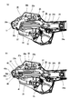
最後に、図13(c)は、結束ミスが発生した場合の電流波形である。具体的には、図14(a)に示すように、何らかの理由で結束具41がクリンチャ18に対して斜めに打ち出されるなどして、図14(b)に示すように、結束具41の脚部41aが正しくクリンチされなかった場合の電流波形である。この図13(c)に示すように、結束具41がクリンチャ18に到達する前の期間(C1よりも前の期間)においては、ドライバ25に大きな抵抗が働かず、ドライバ25に作用する荷重が小さいため、電流値は低く保たれている。そして、結束具41がクリンチャ18に到達してクリンチが開始したタイミング(C1)以降は、ドライバ25に作用する荷重が徐々に上がっていくため、電流値も徐々に上がっていく。しかしながら、結束具41の脚部41aが正しくクリンチされなかった場合には、脚部41aの変形抵抗が大きく上がらないため、その後、ドライバ25に作用する荷重も大きく上がることはない。すなわち、電流値のピークが図13(a)や図13(b)に示す例よりも低くなる。
このように、略U字形の結束具41をクリンチして結束する結束機10においては、電流値のピークを参照することで結束ミスを検出することができる。よって、本実施形態に係る異常処理部120は、モータ20に流れる電流のピーク値が予め定められた所定値に到達しているか否かによって結束ミスを検出するようにしている。
例えば、電流のピーク値と比較する所定値として、図13に示す閾値P1を使用してもよい。この閾値P1は、結束具41の脚部41aが正しくクリンチされた場合にドライバ25に作用する荷重を基に設定されている。このように電流のピーク値と比較する所定値として閾値P1を使用した場合、図13(a)および図13(b)に示すように、電流のピーク値が閾値P1に到達している場合には、結束が正常に実行されたと判断する。一方、図13(c)に示すように、電流のピーク値が閾値P1に到達していない場合には、結束ミスが発生したと判断する。この閾値P1を使用した場合、図13(a)に示すように被結束物50が存在しない状態で結束処理を実行した場合でも、結束ミスとは判断しないように設定することができる。
または、電流のピーク値と比較する所定値として、図13に示す閾値P2を使用してもよい。この閾値P2は、結束具41の脚部41aが正しくクリンチされて、被結束物50を締め付けた場合にドライバ25に作用する荷重を基に設定されている。このように電流のピーク値と比較する所定値として閾値P2を使用した場合、図13(b)に示すように、電流のピーク値が閾値P2に到達している場合には、結束が正常に実行されたと判断する。一方、図13(a)および図13(c)に示すように、電流のピーク値が閾値P2に到達していない場合には、結束ミスが発生したと判断する。この閾値P2を使用した場合、図13(a)に示すように被結束物50が存在しない状態で結束処理を実行した場合には、結束ミスと判断するように設定することができる。
異常処理部120が結束ミスを検出した場合、所定のエラー処理を実行するようにしてもよい。例えば、報知手段38によって、エラーを作業者に報知するようにしてもよい。また、結束ミスを検知したタイミングで機械を停止し、結束前の状態に戻すようにしてもよい。
なお、本実施形態に係る異常処理部120は、電流値のピークを参照することで結束ミスを検出するようにしている。しかしながら、これに代えて、または、これに加えて、他の方法で結束ミスを検出するようにしてもよい。
例えば、電流値が上がり始めるタイミング(図13(a)のA1、図13(b)のB1、図13(c)のC1参照)を検出し、このタイミングが予め定められた所定範囲を逸脱している場合(タイミングが早すぎるまたは遅すぎる場合)には、結束ミスと判断するようにしてもよい。電流値が上がり始めるタイミングは、通常はクリンチ開始のタイミングであるため、クリンチ開始よりも早いタイミングで電流値が上がり始めた場合には、ドライバ25がスムーズに摺動していない、被結束物50が太すぎる、などの何らかの問題が発生していることを検出することができる。また、電流値が上がり始めるタイミングが遅すぎる場合(通常のクリンチ開始のタイミングでも電流値が上がり始めない場合)には、結束具41が正しくセットされていない、などの何らかの問題が発生していることを検出することができる。
なお、電流値が上がり始めるタイミングは、例えば、スイッチ14aが操作されてドライバ25が駆動を開始してから、電流値が上がり始めるまでの時間によって決定するようにしてもよい。
また、電流値がピークに達するタイミング(図13(a)のA2、図13(b)のB2参照)を検出し、このタイミングが予め定められた所定範囲を逸脱している場合(タイミングが早すぎるまたは遅すぎる場合)には、結束ミスと判断するようにしてもよい。電流値がピークに達するタイミングは、通常はクリンチ終了のタイミングである。クリンチ終了のタイミングを参照することにより、例えばクリンチ終了のタイミングが通常よりも早すぎたり遅すぎたりする場合には、被結束物50が太すぎる、正しくクリンチが作動していない、などの何らかの問題が発生していることを検出することができる。
なお、電流値がピークに達するタイミングは、例えば、スイッチ14aが操作されてドライバ25が駆動を開始してから、電流値がピークに達するまでの時間によって決定するようにしてもよい。または、閾値P1を超えてから、電流値がピークに達するまでの時間によって決定するようにしてもよい。または、閾値P1を超えてから、閾値P2に到達するまでの時間によって決定するようにしてもよい。
履歴管理部130は、結束作業の履歴を管理するものである。この履歴管理部130は、例えば、異常処理部120が検出した結束ミスの履歴を記憶することができる。例えば、この履歴管理部130は、機械がリセットされてから何回目の結束でミスが発生したかを記憶することができる。よって、例えば連続して結束作業を行った後に、結束ミスが発生しているか否か、また、いつ結束ミスが発生したのかを確認することができる。このような機能を使用すれば、結束ミスの有無を後から確認することができる。例えば、出荷後に結束不良が判明した場合に、結束不良の原因が結束作業中にあるのか結束作業後にあるのかを後から確認することができる。また、結束ミスの発生頻度を確認することで、作業者の熟練度を判定することができるので、作業指導に役立てることも可能である。また、ロボットを使用して自動で結束作業を行った場合でも、現物を目視確認することなく結束ミスの有無を確認することができる。
また、この履歴管理部130は、電流値測定部60が測定した電流波形の履歴を記憶するようにしてもよい。すなわち、結束ミスが発生した場合だけではなく、結束が正常に行われた場合であっても、モータ20に流れる電流値の測定履歴を記憶するようにしてもよい。このようにすれば、すべての結束履歴を後で確認できるため、作業履歴を残すことができる。このように残した作業履歴は、例えば、結束ミスが発生することなく作業が完了したことの証明として使用することができる。また、作業履歴として残した電流波形を確認することで、被結束物50の締め付け具合を確認することができる。
また、この履歴管理部130は、結束回数の履歴を記憶するようにしてもよい。そして、記憶した結束回数をユーザに表示可能としてもよい。結束回数をユーザに表示する方法としては、例えば、液晶画面などに表示するようにしてもよいし、外部(例えば、スマートフォンなどの端末、制御用の機器、サーバーなど)に出力するようにしてもよい。また、結束回数が予め定められた規定数に到達したときに、報知手段38(表示、音、振動)で報知するようにしてもよい。このとき、報知に使用する規定数はユーザが自由に設定できるようにしてもよい。このように構成すれば、例えば「1つの被結束物50につき5箇所の結束を行う」という作業指示があった場合に、規定数を「5」に設定することで、5回結束するごとに報知が実行されるように設定できる。また、「所定回数(例えば10回)結束後に結束強度を変更する」という作業指示があった場合に、規定数を「10」に設定することで、10回結束するごとに報知が実行されるように設定できる。このような設定により、作業者が結束回数を数える必要がなくなるので、間違いが生じににくく、作業効率を上げることができる。
以下、図16~22を参照しつつ、結束機10における処理フローについて説明する。異常処理部120は、図16におけるステップSA1で、モータ20に流れる電流のピーク値が予め定められた所定値に到達しているか否か、つまり、電流値測定部60によって測定された電流のピーク値が閾値P1以上か否かを判断する。電流のピーク値が閾値P1以上の場合は、異常処理部120は結束が正常に行なわれたと判断し、ステップSA1の処理に戻る。一方、電流のピーク値が閾値P1より小さい場合、異常処理部120は結束が正常に行なわれていない(結束ミスが発生した)と判断し、ステップSA11にて異常処理を行なう。次いで、ステップSA12において履歴管理部130は結束ミスの履歴を記憶する。
異常処理部120は、図17におけるステップSA2で、モータ20に流れる電流のピーク値が予め定められた所定値に到達しているか否か、つまり、電流値測定部60によって測定された電流のピーク値が閾値P2以上か否かを判断する。電流のピーク値が閾値P2以上の場合は、異常処理部120は結束が正常に行なわれたと判断し、ステップSA2の処理に戻る。一方、電流のピーク値が閾値P2よりも小さい場合、異常処理部120は結束が正常に行なわれていない(結束ミスが発生した)と判断し、ステップSA21にて異常処理を行なう。次いで、ステップSA22において履歴管理部130は結束ミスの履歴を記憶する。
異常処理部120は、図18におけるステップSA3で、モータ20に流れる電流値が上がり始めるタイミングA1が予め定められた所定範囲を逸脱しているか否かを判断する。タイミングA1が所定範囲を逸脱していない場合、異常処理部120は結束が正常に行なわれたと判断し、ステップSA3の処理に戻る。一方、タイミングA1が所定範囲を逸脱している場合、異常処理部120は結束が正常に行なわれていない(結束ミスが発生した)と判断し、ステップSA31にて異常処理を行なう。次いで、ステップSA32において履歴管理部130は結束ミスの履歴を記憶する。
異常処理部120は、図19におけるステップSA4で、モータ20に流れる電流値が上がり始めるタイミングB1が予め定められた所定範囲を逸脱しているか否かを判断する。タイミングB1が所定範囲を逸脱していない場合、異常処理部120は結束が正常に行なわれたと判断し、ステップSA4の処理に戻る。一方、タイミングB1が所定範囲を逸脱している場合、異常処理部120は結束が正常に行なわれていない(結束ミスが発生した)と判断し、ステップSA41にて異常処理を行なう。次いで、ステップSA42において履歴管理部130は結束ミスの履歴を記憶する。
異常処理部120は、図20におけるステップSA5で、モータ20に流れる電流値が上がり始めるタイミングC1が予め定められた所定範囲を逸脱しているか否かを判断する。タイミングC1が所定範囲を逸脱していない場合、異常処理部120は結束が正常に行なわれたと判断し、ステップSA5の処理に戻る。一方、タイミングC1が所定範囲を逸脱している場合、異常処理部120は結束が正常に行なわれていない(結束ミスが発生した)と判断し、ステップSA51にて異常処理を行なう。次いで、ステップSA52において履歴管理部130は結束ミスの履歴を記憶する。
異常処理部120は、図21におけるステップSA6で、モータ20に流れる電流値がピークに達するタイミングA2が予め定められた所定範囲を逸脱しているか否かを判断する。タイミングA2が所定範囲を逸脱していない場合は、異常処理部120は結束が正常に行なわれたと判断し、ステップSA6の処理に戻る。一方、タイミングA2が所定範囲を逸脱している場合は、異常処理部120は結束が正常に行なわれていない(結束ミスが発生した)と判断し、ステップSA61にて異常処理を行なう。次いでステップSA62において履歴管理部130は結束ミスの履歴を記憶する。
異常処理部120は、図22におけるステップSA7で、モータ20に流れる電流値がピークに達するタイミングB2が予め定められた所定範囲を逸脱しているか否かを判断する。タイミングB2が所定範囲を逸脱していない場合は、異常処理部120は結束が正常に行なわれたと判断し、ステップSA7の処理に戻る。一方、タイミングB2が所定範囲を逸脱している場合、異常処理部120は結束が正常に行なわれていない(結束ミスが発生した)と判断し、ステップSA71にて異常処理を行なう。次いでステップSA72において履歴管理部130は結束ミスの履歴を記憶する。
以上説明したように、本実施形態に係る結束機10は、一対の脚部41aを有する塑性変形可能な結束具41を打ち込んで被結束物50を結束する結束機10であって、モータ20によって駆動して結束具41を打ち出すドライバ25と、ドライバ25に作用する荷重を推定することにより結束ミスを検出する異常処理部120と、を備える。このような構成によれば、ドライバ25に作用する荷重を推定することで、結束具41の脚部41aの変形抵抗や結束の締め付け具合を推定することができる。例えば、ドライバ25に作用する荷重が小さく、結束具41の脚部41aの変形抵抗が小さすぎると判断した場合には、結束具41の脚部41aが正しくクリンチされていないと判断することができる。よって、一対の脚部41aを有する結束具41を打ち込むタイプの結束機10の特性を活かして、目視確認しなくても結束ミスを検出することができる。
なお、上記した実施形態においては、結束機10をユーザが把持する前提で説明したが、結束機10をロボットアーム等の機械に取り付けるようにしてもよい。この場合、ロボットアーム等の機械に取り付けられる部分をグリップ部13としてもよい。
このようにロボット制御などにより結束機10を無人設備で使用した場合であっても、目視確認なしで結束ミスを検出することができる。よって、結束作業後に現物を確認する必要がなく、作業性を向上させることができる。
また、上記した実施形態に係る結束機10は、電源接続部12aから電圧供給を受けるように構成したが、これに限らず、結束機10が電源を内蔵してもよいし、結束機10に電池パックを着脱可能としてもよい。また、上記した実施形態に係る結束機10は、制御部21を備えているが、これに限らず、制御部21を機械の外部に配置してもよい。例えば、集中制御などによって結束機10を作動させるようにしてもよい。
また、上記した実施形態においては、手持ち式の結束機10について説明したが、これに限らず、据え置き式の結束機10に本発明を応用してもよい。
また、上記した実施形態においては、異常処理部120は、モータ20に流れる電流値を参照してドライバ25に作用する荷重を推定するようにしたが、これに限らない。
例えば、異常処理部120は、モータ20を回転させるためのパルスを参照してドライバ25に作用する荷重を推定するようにしてもよい。すなわち、ドライバ25に作用する荷重が大きくなれば、ドライバ25の速度が低下するため、モータ20の回転速度も低下し、パルス周期が大きくなる。よって、パルス波形を参照した場合でも、図13に示す電流波形を参照した場合と同様に、ドライバ25に作用する荷重を推定することができる。この場合における結束機10における処理フローを図23に示す。異常処理部120は、ステップSA8でモータ20のパルス周期が閾値P3以上か否かを判断する。モータ20のパルス周期が閾値P3よりも大きくない場合、異常処理部120は結束が正常に行なわれたと判断し、ステップSA8の処理に戻る。一方、モータ20のパルス周期が閾値P3以上の場合、異常処理部120は結束が正常に行なわれていない(結束ミスが発生した)と判断し、ステップSA81にて異常処理を行なう。次いで、ステップSA82において履歴管理部130は結束ミスの履歴を記憶する。
または、ドライバ25またはクリンチャ18に荷重センサを設け、異常処理部120がこの荷重センサの検出結果を参照してドライバ25に作用する荷重を推定するようにしてもよい。このような構成によれば、直接的にドライバ25に作用する荷重を推定することができる。この場合における結束機10における処理フローを図24に示す。異常処理部120は、ステップSA9で荷重センサの検出値が閾値P4以上か否かを判定する。荷重センサの検出値が閾値P4よりも大きくない場合、異常処理部120は結束が正常に行なわれたと判断し、ステップSA9の処理に戻る。一方、荷重センサの検出値が閾値P4以上の場合、異常処理部120は結束が正常に行なわれていない(結束ミスが発生した)と判断し、ステップSA91にて異常処理を行なう。次いで、ステップSA92において履歴管理部130は結束ミスの履歴を記憶する。
また、上記した実施形態においては、ドライバ25に作用する荷重を推定することにより結束ミスを検出するようにしたが、別の方法でも結束ミスを検出することは可能である。
例えば、結束部位を撮影可能なカメラを結束機10または周辺機器に設置し、その撮影画像から、結束ミスや被結束物50の締め付け具合を確認することも可能である。
または、ドライバ25の移動距離(ストローク)を検出するように構成し、ドライバ25の移動距離が正しい範囲にあるか否かを判定することで、結束ミスや被結束物50の締め付け具合を確認することも可能である。
本出願は、2018年8月7日出願の日本特許出願特願2018-148190に基づくものであり、その内容はここに参照として取り込まれる。
本出願は、2018年8月7日出願の日本特許出願特願2018-148190に基づくものであり、その内容はここに参照として取り込まれる。
10 結束機
11 ハウジング
11a 拾いこみ面
12 モータ収容部
12a 電源接続部
13 グリップ部
14 トリガ
14a スイッチ
15 出力部
16 挿入口
17 突出形成部
17a 外側面
17b 内側面
18 クリンチャ
20 モータ
21 制御部
22 駆動機構
23 減速機構
24 ボールねじ
24a ねじ軸
24b ナット
25 ドライバ
26 連動機構
27 スライド部材
27a フック
27b 傾斜部
27c 水平部
28 接続部材
30 ガイド部材
30a 揺動軸
30b 作動ピン
30c 先端部
30d 第1ガイド部
30e 第2ガイド部
35 マガジン部
35a リブ
35b 溝部
36 プッシャ
37 待機部
38 報知手段
40 連結結束具
41 結束具
41a 脚部
41b 接続部
41c 開口部
45 詰まりセンサ
45a 検出部
46 ガイド用センサ
46a 検出部
50 被結束物
60 電流値測定部
110 駆動制御部
120 異常処理部
130 履歴管理部
D1 挿入口の開口方向
D2 結束具の打ち出し方向(ドライバの進退方向)
11 ハウジング
11a 拾いこみ面
12 モータ収容部
12a 電源接続部
13 グリップ部
14 トリガ
14a スイッチ
15 出力部
16 挿入口
17 突出形成部
17a 外側面
17b 内側面
18 クリンチャ
20 モータ
21 制御部
22 駆動機構
23 減速機構
24 ボールねじ
24a ねじ軸
24b ナット
25 ドライバ
26 連動機構
27 スライド部材
27a フック
27b 傾斜部
27c 水平部
28 接続部材
30 ガイド部材
30a 揺動軸
30b 作動ピン
30c 先端部
30d 第1ガイド部
30e 第2ガイド部
35 マガジン部
35a リブ
35b 溝部
36 プッシャ
37 待機部
38 報知手段
40 連結結束具
41 結束具
41a 脚部
41b 接続部
41c 開口部
45 詰まりセンサ
45a 検出部
46 ガイド用センサ
46a 検出部
50 被結束物
60 電流値測定部
110 駆動制御部
120 異常処理部
130 履歴管理部
D1 挿入口の開口方向
D2 結束具の打ち出し方向(ドライバの進退方向)
Claims (7)
- 一対の脚部を有する塑性変形可能な結束具を打ち込んで被結束物を結束する結束機であって、
結束具を打ち出すドライバと、
前記ドライバによって打ち出された結束具の脚部をクリンチして結束を完了させるためのクリンチャと、
前記ドライバに作用する荷重を推定することにより結束ミスを検出する異常処理部と、
を備えることを特徴とする、結束機。 - 前記ドライバを駆動するモータを備え、
前記異常処理部は、前記モータに流れる電流値を参照して前記ドライバに作用する荷重を推定することを特徴とする、請求項1記載の結束機。 - 前記異常処理部は、前記モータに流れる電流のピーク値が予め定められた所定値に到達しているか否かによって結束ミスを検出することを特徴とする、請求項2記載の結束機。
- 前記異常処理部は、前記モータに流れる電流値が上がり始めるタイミング、または、前記モータに流れる電流値がピークに達するタイミングの少なくともいずれかが、予め定められた所定範囲を逸脱している場合に結束ミスを検出することを特徴とする、請求項2記載の結束機。
- 前記ドライバを駆動するモータを備え、
前記異常処理部は、前記モータを回転させるためのパルスを参照して前記ドライバに作用する荷重を推定することを特徴とする、請求項1記載の結束機。 - 前記異常処理部は、前記ドライバまたは前記クリンチャに設けられた荷重センサの検出結果を参照して前記ドライバに作用する荷重を推定することを特徴とする、請求項1記載の結束機。
- 前記異常処理部が検出した結束ミスの履歴を記憶する履歴管理部を備えることを特徴とする、請求項1~6のいずれか1項に記載の結束機。
Applications Claiming Priority (2)
| Application Number | Priority Date | Filing Date | Title |
|---|---|---|---|
| JP2018148190A JP2020023337A (ja) | 2018-08-07 | 2018-08-07 | 結束機 |
| JP2018-148190 | 2018-08-07 |
Publications (1)
| Publication Number | Publication Date |
|---|---|
| WO2020031769A1 true WO2020031769A1 (ja) | 2020-02-13 |
Family
ID=69415246
Family Applications (1)
| Application Number | Title | Priority Date | Filing Date |
|---|---|---|---|
| PCT/JP2019/029616 Ceased WO2020031769A1 (ja) | 2018-08-07 | 2019-07-29 | 結束機 |
Country Status (3)
| Country | Link |
|---|---|
| JP (1) | JP2020023337A (ja) |
| TW (1) | TW202012093A (ja) |
| WO (1) | WO2020031769A1 (ja) |
Citations (6)
| Publication number | Priority date | Publication date | Assignee | Title |
|---|---|---|---|---|
| JPH09156608A (ja) * | 1995-12-06 | 1997-06-17 | Bentatsuku:Kk | 結束機の制御方法及び装置 |
| JPH1045105A (ja) * | 1996-08-02 | 1998-02-17 | Max Co Ltd | 鉄筋結束機におけるワイヤ絡み防止方法 |
| JP2001039413A (ja) * | 1999-07-28 | 2001-02-13 | Max Co Ltd | 袋結束機におけるモータのブレーキ制御方法 |
| JP2002332014A (ja) * | 2001-05-01 | 2002-11-22 | Furukawa Mfg Co Ltd | 包袋の結束装置 |
| JP2004142782A (ja) * | 2002-10-24 | 2004-05-20 | Max Co Ltd | 鉄筋結束機 |
| JP2018184201A (ja) * | 2017-04-27 | 2018-11-22 | マックス株式会社 | 結束具及び連結結束具 |
-
2018
- 2018-08-07 JP JP2018148190A patent/JP2020023337A/ja active Pending
-
2019
- 2019-07-29 WO PCT/JP2019/029616 patent/WO2020031769A1/ja not_active Ceased
- 2019-07-29 TW TW108126745A patent/TW202012093A/zh unknown
Patent Citations (6)
| Publication number | Priority date | Publication date | Assignee | Title |
|---|---|---|---|---|
| JPH09156608A (ja) * | 1995-12-06 | 1997-06-17 | Bentatsuku:Kk | 結束機の制御方法及び装置 |
| JPH1045105A (ja) * | 1996-08-02 | 1998-02-17 | Max Co Ltd | 鉄筋結束機におけるワイヤ絡み防止方法 |
| JP2001039413A (ja) * | 1999-07-28 | 2001-02-13 | Max Co Ltd | 袋結束機におけるモータのブレーキ制御方法 |
| JP2002332014A (ja) * | 2001-05-01 | 2002-11-22 | Furukawa Mfg Co Ltd | 包袋の結束装置 |
| JP2004142782A (ja) * | 2002-10-24 | 2004-05-20 | Max Co Ltd | 鉄筋結束機 |
| JP2018184201A (ja) * | 2017-04-27 | 2018-11-22 | マックス株式会社 | 結束具及び連結結束具 |
Also Published As
| Publication number | Publication date |
|---|---|
| JP2020023337A (ja) | 2020-02-13 |
| TW202012093A (zh) | 2020-04-01 |
Similar Documents
| Publication | Publication Date | Title |
|---|---|---|
| US10427284B2 (en) | Fastener driving tool | |
| EP1584419B1 (en) | Method for operating a power driver | |
| US9533408B2 (en) | Fastening tool | |
| CN110997242B (zh) | 打入机 | |
| CN110788807A (zh) | 打入工具 | |
| JP2021513906A (ja) | 電動ハンドルを有する外科用ステープラ | |
| KR102576948B1 (ko) | 케이블 타이를 설치하기 위한 수동자동 장치 | |
| US20160376041A1 (en) | Battery powered flat tensioner tool | |
| EP1449623B1 (en) | Power Tools | |
| JP6992657B2 (ja) | 結束機 | |
| JP2009184050A (ja) | 留め具打込機 | |
| CA2561961A1 (en) | Electronic fastening tool | |
| CA2218455A1 (en) | Automatic cable tie installing tool | |
| JP6123552B2 (ja) | 留め具打込機 | |
| JP5110300B2 (ja) | 釘打機およびその釘射出方法 | |
| JP2020023337A (ja) | 結束機 | |
| TWI714842B (zh) | 捆束機 | |
| US11926029B2 (en) | Apparatus, driving-in device and method | |
| WO2018199199A1 (ja) | 結束具及び連結結束具 | |
| WO2018199200A1 (ja) | 結束機 | |
| JP2018184213A (ja) | 結束機 | |
| WO2005098886A2 (en) | Method for controlling a power driver |
Legal Events
| Date | Code | Title | Description |
|---|---|---|---|
| 121 | Ep: the epo has been informed by wipo that ep was designated in this application |
Ref document number: 19847764 Country of ref document: EP Kind code of ref document: A1 |
|
| NENP | Non-entry into the national phase |
Ref country code: DE |
|
| 122 | Ep: pct application non-entry in european phase |
Ref document number: 19847764 Country of ref document: EP Kind code of ref document: A1 |