WO2020031736A1 - バッテリシステムとバッテリシステムを備える車両及び蓄電装置 - Google Patents
バッテリシステムとバッテリシステムを備える車両及び蓄電装置 Download PDFInfo
- Publication number
- WO2020031736A1 WO2020031736A1 PCT/JP2019/029342 JP2019029342W WO2020031736A1 WO 2020031736 A1 WO2020031736 A1 WO 2020031736A1 JP 2019029342 W JP2019029342 W JP 2019029342W WO 2020031736 A1 WO2020031736 A1 WO 2020031736A1
- Authority
- WO
- WIPO (PCT)
- Prior art keywords
- battery system
- insulating
- battery
- rectangular
- insulating case
- Prior art date
Links
Images


Classifications
-
- H—ELECTRICITY
- H01—ELECTRIC ELEMENTS
- H01M—PROCESSES OR MEANS, e.g. BATTERIES, FOR THE DIRECT CONVERSION OF CHEMICAL ENERGY INTO ELECTRICAL ENERGY
- H01M10/00—Secondary cells; Manufacture thereof
- H01M10/60—Heating or cooling; Temperature control
- H01M10/65—Means for temperature control structurally associated with the cells
- H01M10/658—Means for temperature control structurally associated with the cells by thermal insulation or shielding
-
- B—PERFORMING OPERATIONS; TRANSPORTING
- B60—VEHICLES IN GENERAL
- B60R—VEHICLES, VEHICLE FITTINGS, OR VEHICLE PARTS, NOT OTHERWISE PROVIDED FOR
- B60R16/00—Electric or fluid circuits specially adapted for vehicles and not otherwise provided for; Arrangement of elements of electric or fluid circuits specially adapted for vehicles and not otherwise provided for
- B60R16/02—Electric or fluid circuits specially adapted for vehicles and not otherwise provided for; Arrangement of elements of electric or fluid circuits specially adapted for vehicles and not otherwise provided for electric constitutive elements
- B60R16/04—Arrangement of batteries
-
- H—ELECTRICITY
- H01—ELECTRIC ELEMENTS
- H01M—PROCESSES OR MEANS, e.g. BATTERIES, FOR THE DIRECT CONVERSION OF CHEMICAL ENERGY INTO ELECTRICAL ENERGY
- H01M10/00—Secondary cells; Manufacture thereof
- H01M10/60—Heating or cooling; Temperature control
- H01M10/61—Types of temperature control
- H01M10/613—Cooling or keeping cold
-
- H—ELECTRICITY
- H01—ELECTRIC ELEMENTS
- H01M—PROCESSES OR MEANS, e.g. BATTERIES, FOR THE DIRECT CONVERSION OF CHEMICAL ENERGY INTO ELECTRICAL ENERGY
- H01M10/00—Secondary cells; Manufacture thereof
- H01M10/60—Heating or cooling; Temperature control
- H01M10/62—Heating or cooling; Temperature control specially adapted for specific applications
- H01M10/625—Vehicles
-
- H—ELECTRICITY
- H01—ELECTRIC ELEMENTS
- H01M—PROCESSES OR MEANS, e.g. BATTERIES, FOR THE DIRECT CONVERSION OF CHEMICAL ENERGY INTO ELECTRICAL ENERGY
- H01M10/00—Secondary cells; Manufacture thereof
- H01M10/60—Heating or cooling; Temperature control
- H01M10/64—Heating or cooling; Temperature control characterised by the shape of the cells
- H01M10/647—Prismatic or flat cells, e.g. pouch cells
-
- H—ELECTRICITY
- H01—ELECTRIC ELEMENTS
- H01M—PROCESSES OR MEANS, e.g. BATTERIES, FOR THE DIRECT CONVERSION OF CHEMICAL ENERGY INTO ELECTRICAL ENERGY
- H01M10/00—Secondary cells; Manufacture thereof
- H01M10/60—Heating or cooling; Temperature control
- H01M10/65—Means for temperature control structurally associated with the cells
- H01M10/655—Solid structures for heat exchange or heat conduction
- H01M10/6556—Solid parts with flow channel passages or pipes for heat exchange
-
- H—ELECTRICITY
- H01—ELECTRIC ELEMENTS
- H01M—PROCESSES OR MEANS, e.g. BATTERIES, FOR THE DIRECT CONVERSION OF CHEMICAL ENERGY INTO ELECTRICAL ENERGY
- H01M10/00—Secondary cells; Manufacture thereof
- H01M10/60—Heating or cooling; Temperature control
- H01M10/65—Means for temperature control structurally associated with the cells
- H01M10/656—Means for temperature control structurally associated with the cells characterised by the type of heat-exchange fluid
- H01M10/6561—Gases
- H01M10/6563—Gases with forced flow, e.g. by blowers
-
- H—ELECTRICITY
- H01—ELECTRIC ELEMENTS
- H01M—PROCESSES OR MEANS, e.g. BATTERIES, FOR THE DIRECT CONVERSION OF CHEMICAL ENERGY INTO ELECTRICAL ENERGY
- H01M50/00—Constructional details or processes of manufacture of the non-active parts of electrochemical cells other than fuel cells, e.g. hybrid cells
- H01M50/20—Mountings; Secondary casings or frames; Racks, modules or packs; Suspension devices; Shock absorbers; Transport or carrying devices; Holders
- H01M50/204—Racks, modules or packs for multiple batteries or multiple cells
- H01M50/207—Racks, modules or packs for multiple batteries or multiple cells characterised by their shape
- H01M50/209—Racks, modules or packs for multiple batteries or multiple cells characterised by their shape adapted for prismatic or rectangular cells
-
- H—ELECTRICITY
- H01—ELECTRIC ELEMENTS
- H01M—PROCESSES OR MEANS, e.g. BATTERIES, FOR THE DIRECT CONVERSION OF CHEMICAL ENERGY INTO ELECTRICAL ENERGY
- H01M50/00—Constructional details or processes of manufacture of the non-active parts of electrochemical cells other than fuel cells, e.g. hybrid cells
- H01M50/20—Mountings; Secondary casings or frames; Racks, modules or packs; Suspension devices; Shock absorbers; Transport or carrying devices; Holders
- H01M50/262—Mountings; Secondary casings or frames; Racks, modules or packs; Suspension devices; Shock absorbers; Transport or carrying devices; Holders with fastening means, e.g. locks
- H01M50/264—Mountings; Secondary casings or frames; Racks, modules or packs; Suspension devices; Shock absorbers; Transport or carrying devices; Holders with fastening means, e.g. locks for cells or batteries, e.g. straps, tie rods or peripheral frames
-
- H—ELECTRICITY
- H01—ELECTRIC ELEMENTS
- H01M—PROCESSES OR MEANS, e.g. BATTERIES, FOR THE DIRECT CONVERSION OF CHEMICAL ENERGY INTO ELECTRICAL ENERGY
- H01M50/00—Constructional details or processes of manufacture of the non-active parts of electrochemical cells other than fuel cells, e.g. hybrid cells
- H01M50/20—Mountings; Secondary casings or frames; Racks, modules or packs; Suspension devices; Shock absorbers; Transport or carrying devices; Holders
- H01M50/289—Mountings; Secondary casings or frames; Racks, modules or packs; Suspension devices; Shock absorbers; Transport or carrying devices; Holders characterised by spacing elements or positioning means within frames, racks or packs
- H01M50/291—Mountings; Secondary casings or frames; Racks, modules or packs; Suspension devices; Shock absorbers; Transport or carrying devices; Holders characterised by spacing elements or positioning means within frames, racks or packs characterised by their shape
-
- H—ELECTRICITY
- H01—ELECTRIC ELEMENTS
- H01M—PROCESSES OR MEANS, e.g. BATTERIES, FOR THE DIRECT CONVERSION OF CHEMICAL ENERGY INTO ELECTRICAL ENERGY
- H01M50/00—Constructional details or processes of manufacture of the non-active parts of electrochemical cells other than fuel cells, e.g. hybrid cells
- H01M50/20—Mountings; Secondary casings or frames; Racks, modules or packs; Suspension devices; Shock absorbers; Transport or carrying devices; Holders
- H01M50/289—Mountings; Secondary casings or frames; Racks, modules or packs; Suspension devices; Shock absorbers; Transport or carrying devices; Holders characterised by spacing elements or positioning means within frames, racks or packs
- H01M50/293—Mountings; Secondary casings or frames; Racks, modules or packs; Suspension devices; Shock absorbers; Transport or carrying devices; Holders characterised by spacing elements or positioning means within frames, racks or packs characterised by the material
-
- Y—GENERAL TAGGING OF NEW TECHNOLOGICAL DEVELOPMENTS; GENERAL TAGGING OF CROSS-SECTIONAL TECHNOLOGIES SPANNING OVER SEVERAL SECTIONS OF THE IPC; TECHNICAL SUBJECTS COVERED BY FORMER USPC CROSS-REFERENCE ART COLLECTIONS [XRACs] AND DIGESTS
- Y02—TECHNOLOGIES OR APPLICATIONS FOR MITIGATION OR ADAPTATION AGAINST CLIMATE CHANGE
- Y02E—REDUCTION OF GREENHOUSE GAS [GHG] EMISSIONS, RELATED TO ENERGY GENERATION, TRANSMISSION OR DISTRIBUTION
- Y02E60/00—Enabling technologies; Technologies with a potential or indirect contribution to GHG emissions mitigation
- Y02E60/10—Energy storage using batteries
Definitions
- the present invention relates to a battery system in which a number of rectangular battery cells are insulated and stacked, a vehicle including the battery system, and a power supply device.
- a separator is arranged between the stacked rectangular battery cells.
- the separator insulates adjacently stacked rectangular battery cells.
- a pair of end plates are arranged on both end surfaces, the end plates are connected by bind bars, and the battery stack is fixed in a pressurized state with a separator interposed between the rectangular battery cells.
- a potential difference occurs between the outer cans of adjacent square battery cells.
- Insulate rectangular battery cells with a potential difference to prevent short-circuits, prevent electrical leakage and short-circuits due to condensation water adhering to the surface of the outer can, and furthermore, when certain rectangular battery cells are in a state of thermal runaway
- a plastic separator is arranged between the rectangular battery cells.
- the battery system is covered with a heat-shrinkable tube to insulate each rectangular battery cell in a more ideal state.
- the heat-shrinkable tube has a bag shape and is heated and shrunk in a state where the rectangular battery cells are inserted, and adheres to the surface of the outer can.
- a prismatic battery cell in which the heat shrink tube is in close contact with the surface of the outer can can be laminated with improved insulation properties.
- a battery system in which a rectangular battery cell is covered with a heat-shrinkable tube has the drawback that the production is troublesome, the yield is low, and the production cost is high. This is because it is extremely difficult to accurately adhere the heat-shrinkable tube to the surface of the outer can of the rectangular battery cell.
- the heat-shrinkable tube needs to be exposed to necessary portions, such as the electrode terminals of the rectangular battery cells and the opening of the discharge valve, and then heat-shrink so as to completely cover the other portions, so that the heat-shrinkable tube adheres to the outer can surface.
- the prismatic battery cell Since the prismatic battery cell has a rectangular parallelepiped outer can, if the prismatic battery cell is placed in a bag-like heat-shrinkable tube and then thermally shrunk, the shrinkage rate will be partially different, and loosening tends to occur in the area where the shrinkage rate is small. In a portion having a large shrinkage, adverse effects such as breakage occur.
- the present invention has been developed with the object of overcoming the above disadvantages.
- One of the objects of the present invention is to efficiently insulate and stack rectangular battery cells and efficiently mass-produce them at a high yield. It is an object of the present invention to provide a technology capable of reducing manufacturing costs.
- a battery system includes a battery stack in which a plurality of rectangular battery cells are stacked with an insulating material interposed therebetween, a pair of end plates arranged at both ends of the battery stack, and a pair of the end plates.
- a power supply device comprising a bind bar formed by connecting end plates, wherein the insulating material is formed of an insulating case of a plastic molded body in which the rectangular battery cells are arranged in a fixed state in a fixed position inside.
- the insulating case is integrally formed and connected to an insulating plate sandwiched between the adjacent rectangular battery cells and an insulating wall connected to an outer peripheral edge of the insulating plate; Further, the insulating case includes a pair of cover cases divided in the thickness direction of the prismatic battery cells, and the pair of cover cases are connected to each other so that the rectangular battery is positioned at a fixed position in the insulating case. And placing the Le, the battery stack has the rectangular battery cells are stacked insulating battery unit formed by arranging in the interior of the insulating case.
- a vehicle including a battery system including the components of the above-described embodiments includes a battery system, a running motor supplied with power from the battery system, and a vehicle body including the battery system and the motor. And wheels driven by the motor to drive the vehicle body.
- a power storage device including a battery system including the components of the above aspects includes the battery system, and a power supply controller that controls charging and discharging of the battery system, wherein the power supply controller is configured to control the rectangular shape by external power.
- the battery cell can be charged and the battery cell is controlled to be charged.
- the above battery system has the features that the rectangular battery cells can be reliably insulated and stacked, and the production cost can be reduced with high yield and high production efficiency. That is, the battery system described above arranges rectangular battery cells in a plastic insulating case, and stacks the rectangular battery cells in an insulated battery unit whose surface is insulated by the insulating case. This is because both the insulating separator and the insulating separator are omitted.
- the insulating case is divided into a pair of cover cases, and the rectangular battery cells are placed in the divided cover cases and the cover cases are connected to insulate the surfaces of the rectangular battery cells.
- the surface of the rectangular battery cell can be more reliably insulated than the separator placed between the battery cells. This is because the surface of the rectangular battery cell can be covered by connecting the pair of cover cases to accurate positions.
- FIG. 2 is an exploded perspective view of the battery system shown in FIG. It is a perspective view of an insulated battery unit.
- FIG. 4 is an exploded perspective view of the insulated battery unit shown in FIG. 3.
- FIG. 9 is an enlarged sectional view showing a hinge portion of the insulating case, and
- FIG. 5A shows a state in which the cover case is opened, as shown in FIG.
- FIG. 5B is a diagram showing a state where the cover case is closed.
- FIG. 10 is an enlarged sectional view showing a fitting connection portion of an insulating case, and
- FIG. 6A shows a state in which the cover case is opened, as shown in FIG. FIG.
- FIG. 6B is a view showing a state where the cover case is closed. It is a top view showing the state where an insulated battery unit is laminated. It is a side view which shows the state which laminates an insulated battery unit. It is an expanded sectional view of an insulated battery unit, and is a sectional view which makes a section a plane parallel to a lamination surface of a rectangular battery cell. It is sectional drawing which shows another example of an insulating case and is a sectional view which makes a cut surface a surface parallel to the lamination surface of a square battery cell.
- FIG. 2 is a block diagram illustrating an example in which a battery system is mounted on a hybrid vehicle that runs on an engine and a motor.
- FIG. 3 is a block diagram illustrating an example in which a battery system is mounted on an electric vehicle running only by a motor.
- FIG. 3 is a block diagram illustrating an example in which a battery system is used for a power storage device.
- an insulating separator is sandwiched between adjacent rectangular battery cells in order to insulate adjacent rectangular battery cells.
- the insulating separator can insulate the surface of the rectangular battery cell by providing an insulating wall that insulates the surface of the rectangular battery cell in an integral structure.
- the separator since the separator is fitted to the adjacent rectangular battery cell and is arranged at a fixed position by the rectangular battery cell, it is difficult to accurately specify the relative position of the adjacently disposed separator. This is because the relative displacement of the stacked rectangular battery cells causes the relative positions of the adjacently stacked separators to be deviated. In the manufacturing process, it is difficult to eliminate the dimensional error of the outer shape of the prismatic battery cells, and in the assembling process, it is difficult to accurately adjust the lamination positions of all the prismatic battery cells and laminate them.
- the present invention further develops a technology capable of efficiently producing a large number of batteries while reliably insulating the stacked rectangular battery cells by further examining and improving the structure for insulating the rectangular battery cells. It has been reached.
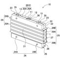
- the battery system includes a battery stack 3 in which a plurality of prismatic battery cells 1 are stacked via an insulating material 2, a pair of end plates 4 disposed at both ends of the battery stack 3, and a pair of end plates 4. And a bind bar 5 formed by linking them.
- the insulating material 2 is constituted by an insulating case 20 of a plastic molded body in which the rectangular battery cells 1 are arranged at a fixed position inside the fitting state.
- the insulating case 20 integrally connects an insulating plate 21 sandwiched between the adjacent rectangular battery cells 1 and an insulating wall 22 connected to the outer peripheral edge of the insulating plate 21. .
- the insulating case 20 includes a pair of cover cases 20A divided in the thickness direction of the rectangular battery cells 1.
- the pair of cover cases 20A are connected to each other, and the rectangular battery cells 1 are fixed at fixed positions in the insulating case 20.
- the battery stack 3 has an insulated battery unit 10 in which the rectangular battery cells 1 are arranged inside an insulating case 20.
- a pair of cover cases 20A may be connected via a hinge 23 formed integrally.
- the relative positions of the pair of cover cases are accurately specified and integrally formed, so that the insulating cases can be mass-produced at low cost.
- the pair of cover cases can be accurately connected without displacement while covering the rectangular battery cells. With the structure that can be connected without displacement, the gap at the connection edge can be reduced. This is because the gap generated due to the relative position of the cover case being shifted can be reduced. Therefore, the rectangular battery cell surface can be covered and insulated in an ideal state.
- the hinge 23 may be provided so as to be connected to the outer peripheral edge of the insulating wall 22 so that the thickness of the hinge 23 is thinner than the insulating wall 22.
- the thin and easily deformable hinges are bent with the prismatic battery cells arranged inside, and the pair of cover cases are easily and accurately connected to insulate the surface of the prismatic battery cells. it can.
- the hinge portion 23 may be connected to the insulating wall 22 that covers the bottom surface 1B or the top surface 1C of the rectangular battery cell 1. Further, the hinge portion 23 may be provided so as to be connected to the insulating wall 22 that covers the vertical surface 1A of the rectangular battery cell 1.
- the pair of cover cases 20 ⁇ / b> A may have a configuration in which the facing surfaces of the insulating walls 22 have the fitting connection portions 30 that are connected to fixed positions by the fitting structure.
- the pair of cover cases can be connected at an accurate position by connecting the fitting connection portions of the insulating wall in a state where the rectangular battery cells are arranged inside.
- the battery system may have a configuration in which a discharge opening 25 for dew condensation water adhering to the surface of the rectangular battery cell 1 is provided at the bottom of the insulating case 20.
- This battery system can smoothly discharge the dew water adhering to the surface of the rectangular battery cell to the outside, and can prevent adverse effects such as electric leakage, short circuit, and corrosion due to the dew water.
- a discharge gap 26 may be provided between the insulating case 20 and the rectangular battery cell 1, and the discharge gap 26 may be connected to the discharge opening 25.
- dew water adhering to the surface of the rectangular battery cell can be smoothly guided to the discharge opening and discharged quickly.
- the discharge gap 26 may be configured to be inclined downward toward the discharge opening 25.
- This battery system has a feature that the dew water flowing into the discharge gap flows down naturally and can be discharged to the outside through the discharge opening.
- the insulating case 20 may have a configuration in which the concave-convex connecting portions 24 having a fitting structure connected to each other at fixed positions are provided on the opposing stacked surfaces in the stacked state.
- the relative positions of adjacent insulated battery units can be accurately specified and stacked. Therefore, in the assembling process, a large number of insulated battery units can be easily stacked without displacement and efficiently manufactured. In addition, it is possible to prevent the displacement of the insulated battery unit in the stacked state.
- the battery stack 3 has the heat insulating sheet 7 disposed between the adjacent rectangular battery cells 1, and the insulating case 20 holds the heat insulating sheet 7 at the fixed position via the uneven connecting portion 24 formed on the stacking surface. May be arranged.
- a heat insulating sheet can be disposed at a fixed position between adjacent rectangular battery cells via an uneven connection portion provided on a laminated surface of an insulating case. There is a feature that the induction of thermal runaway can be effectively prevented.
- the concave / convex connecting portion 24 includes a fitting convex portion 24A provided on one insulating case and a fitting concave portion 24B provided on the other insulating case 20, and the heat insulating sheet 7 has a through hole through which the fitting convex portion 24A is inserted.
- the heat-insulating sheet 7 may be disposed between the facing insulating cases 20 by connecting the fitting protrusion 24A penetrating the heat-insulating sheet 7 to the fitting recess 24B.
- the heat-insulating sheet can be arranged at an accurate position between the adjacent insulating cases by inserting the fitting protrusions into the through-holes provided in the heat-insulating sheet and connecting them to the fitting recesses. Further, in a state in which the insulated battery units are stacked to form a battery stack, the heat insulating sheet is arranged at a fixed position without displacement, thereby effectively preventing the thermal runaway from being induced for a long period of time.
- the insulating case 20 may be provided with a ventilation groove 27 between the insulating case 20 and the surface of the rectangular battery cell 1 arranged inside.
- the insulating material on the surface of the rectangular battery cell can be used in combination with a part for forcibly cooling the rectangular battery cell. Therefore, there is a feature that the rectangular battery cells can be insulated while being forcibly cooled.
- FIGS. 1 and 2 illustrate a battery system 100 mounted on a vehicle such as a hybrid car, a plug-in hybrid car, an electric vehicle, and supplies electric power to a traveling motor to drive the vehicle.
- the battery system 100 shown in these figures includes a battery stack 3 in which a plurality of rectangular battery cells 1 are stacked via an insulating material 2, and a pair of end plates 4 disposed at both ends of the battery stack 3. And a bind bar 5 that fixes both ends to the end plate 4 and fixes the battery stack 3 in a pressurized state.
- the prismatic battery cell 1 is a lithium ion battery.
- the rectangular battery cell is not limited to a lithium ion battery, and any rechargeable battery, for example, a nonaqueous electrolyte secondary battery other than a lithium ion battery, a nickel metal hydride battery, or the like can be used.
- the prismatic battery cell 1 is one in which an electrode body in which positive and negative electrode plates are stacked is housed in a case and filled with an electrolytic solution.
- the opening of the outer can that is formed in a square cylindrical shape that closes the bottom is closed with a sealing plate.
- the outer can is manufactured by deep drawing a metal plate such as aluminum or an aluminum alloy.
- the case of the stacked rectangular battery cells is formed into a thin rectangular shape.
- the sealing plate is also made of a metal plate such as aluminum or an aluminum alloy.
- positive and negative electrode terminals 13 are fixed to both ends via an insulating material.
- the positive and negative electrode terminals 13 are connected to built-in positive and negative electrode plates.
- the outer can made of a metal plate is not connected to the electrode via the lead wire.
- the outer can since the outer can is connected to the electrode via the electrolytic solution, it has an intermediate potential between the positive and negative electrodes.
- one electrode terminal can be connected to one electrode by a lead wire.
- This rectangular battery cell can be fixed to the sealing plate without insulating the electrode terminals connected to the outer can.
- the sealing plate is provided with an opening 12 of the discharge valve 11. The discharge valve 11 opens when the internal pressure of the case becomes higher than a set value, thereby preventing the case from being damaged. When the discharge valve 11 opens, the internal gas is discharged to the outside through the opening 12 of the sealing plate.
- an opening 12 of a discharge valve 11 is provided in a sealing plate.
- This outer can can discharge gas from the opening 12 of the discharge valve 11 that opens. This is because gas is stored inside the case.
- the prismatic battery cell 1 can also be provided with an opening for a discharge valve at the bottom or side of the outer can.
- the electrolytic solution is discharged from the rectangular battery cell 1 when the discharge valve 11 is opened.
- the electrolyte is a conductive liquid, and when the electrolyte is discharged, the touch portion may be short-circuited.
- the prismatic battery cell 1 in which the discharge valve 11 is provided on the sealing plate of the case can discharge gas from the discharge valve 11 that opens to lower the internal pressure. For this reason, when the discharge valve 11 is opened, the discharge of the electrolytic solution is restricted, and the adverse effect of the electrolytic solution can be reduced.
- the battery stack 3 includes a plurality of prismatic battery cells 1 that are insulated by an insulating material 2 and stacked.
- the insulating material 2 is an insulating case 20 of a plastic molded body in which the rectangular battery cells 1 are arranged in a fixed position inside the fitting.
- resins having excellent heat resistance and insulating properties such as polycarbonate.
- the present invention is not limited to this, and thermoplastic resins such as polypropylene and polyamide can be used. Further, a thermosetting resin having excellent heat resistance can also be used.
- the insulating case 20 is provided with an insulating wall 22 on the outer periphery of a rectangular insulating plate 21 substantially equal in size to both sides of the rectangular battery cell 1, and a rectangular battery inside the insulating wall 22. Cell 1 is arranged.
- the insulating plate 21 is interposed between the adjacent stacked rectangular battery cells 1 to insulate the rectangular battery cells 1 from each other.
- the insulating case 20 includes the prismatic battery cells 1 therein to form the insulating battery unit 10. Further, a plurality of insulated battery units 10 are stacked to form a battery stack 3.
- the insulated battery units 10 each having the rectangular battery cells 1 arranged in the insulating case 20 are stacked, two layers of insulating plates 21 are arranged between the rectangular battery cells 1. This is because each of the adjacent rectangular battery cells 1 is housed in the insulating case 20 and stacked.
- the insulating case 20 has an insulating wall 22 provided on the outer peripheral edge of the insulating plate 21.
- the insulating plate 21 and the insulating wall 22 are integrally formed, and the insulating wall 22 is connected to the insulating plate 21.
- the insulating case 20 is constituted by a pair of cover cases 20A that are divided in the thickness direction of the rectangular battery cell 1 so that the rectangular battery cell 1 can be easily stored inside when opened.
- the rectangular battery cells 1 are set inside with the pair of cover cases 20A opened, and the pair of cover cases 20A are closed and connected to each other in this state, so that the rectangular battery cells 1 Place.
- the battery system 100 is configured such that each of the rectangular battery cells 1 is disposed inside the cover case 20 ⁇ / b> A, and the rectangular battery cells 1 are insulated by the insulating case 20. It is a laminate 3.
- a pair of cover cases 20A are connected by a hinge 23 which is integrally formed.
- the hinge portion 23 is formed with a connecting portion thinner than the insulating wall 22 so that it can be bent at an accurate position.
- the hinge portion 23 in the figure is provided on the insulating wall 22 that covers the upper surface 1C of the rectangular battery cell 1.
- the hinge portion 23 is formed in a shape in which the joint interface of the insulating wall 22 to be connected can be in close contact with the pair of cover cases 20A in a connected state.
- one side edge of the joint interface of the insulating wall 22 and one side edge which is outside when the cover case 20A is opened are connected by a thin hinge portion 23.
- the cover case 20A In a state where the cover case 20A is closed (see FIG. 5B), that is, in a state where the opposing insulating walls 22 are linearly arranged, the cover case 20A slightly expands, and the expanded hinge 23 elastically contracts. , And a structure in which the bonding interface of the insulating wall 22 is in close contact.
- the hinge portion 23 closely adheres the insulating wall 22 without any gap, and insulates the outer peripheral surface of the rectangular battery cell 1 in an ideal state.
- the insulating case 20 can be mass-produced at low cost.
- the rectangular battery cell 1 is set in one of the cover cases 20A with the cover case 20A opened, and in this state, the hinge portion 23 is bent to connect the two cover cases 20A to form a rectangular shape. Since the battery cell 1 can be covered, there is also a feature that the pair of cover cases 20A can be accurately connected without positional displacement.
- the structure in which the two cover cases 20A can be connected without displacement is characterized in that the gap between the connection edges of the insulating wall 22 can be reduced. This is because the relative position of the cover case 20A causes the gap between the connection edges of the insulating wall 22 to be widened. For this reason, the pair of cover cases 20 ⁇ / b> A are connected by the integrally formed hinge 23, and the insulating case 20 has a feature that the surface of the rectangular battery cell 1 can be covered and insulated in an ideal state.
- the hinge portion 23 is provided by connecting to the insulating wall 22 that covers the upper surface 1C of the rectangular battery cell 1. The hinge portion covers the bottom surface of the rectangular battery cell. It may be provided on a wall or an insulating wall covering both side surfaces of the rectangular battery cell.
- the insulating case 20 is provided with a fitting connection portion 30 that is connected to a fixed position by a fitting structure on the facing surfaces of the insulating walls 22 facing each other of the pair of cover cases 20A.
- the insulating case 20 shown in FIG. 4 has a fitting connection portion 30 provided on the insulating wall 22 opposite to the insulating wall 22 provided with the hinge portion 23.
- FIG. 6 is an enlarged cross-sectional view illustrating an example of the fitting connection portion 30.
- the fitting connecting portion 30 is provided with a locking hook 31 protruding from a connecting edge of one insulating wall 22 integrally formed thereon, and a locking hook 31 is provided on a connecting edge of the other insulating wall 22.
- a locking portion 32 for guiding and locking the guide 31 is provided.
- the locking hook 31 has a shape extending along the other insulating wall 22 to be connected, and is provided with a hook-shaped locking projection 31a at the tip.
- the locking projection 31 a has a tapered surface facing the locking portion 32 and has a shape that can be smoothly guided to the locking portion 32.
- the insulating wall 22 provided with the locking portion 32 is provided with a notch 33 for guiding the locking hook 31, and a notch is formed at an opening edge of the notch 33 and on the outer surface on the end face side of the insulating wall 22.
- a bridging portion is provided to connect the facing edges of 33 in a state of partially bridging them to form a locking portion 32.
- the locking portion 32 locks the locking projection 31 a of the locking hook 31 while guiding the locking hook 31 to the notch 33.
- the locking portion 32 is provided with a locking surface 32a that engages with the locking projection 31a so as to guide the locking hook 31 and prevent the locking hook 31 from coming off.
- the locking surface 32a is a surface perpendicular to the surface of the insulating wall 22, and locks the locking projection 31a so that the locking hook 31 does not come off.
- the locking hook 31 and the locking portion 32 are provided at positions where the connecting edges of the insulating wall 22 can be connected without any gap.
- the cover case 20A is provided with a plurality of locking hooks and locking portions separated in the longitudinal direction of the connection edge of the insulating wall 22, or provided with locking hooks and locking portions over the entire connection edge of the insulating wall. You can also. 6 can easily connect the pair of insulating walls 22 by locking the locking hooks 31 to the locking portions 32.
- the connecting structure of the insulating walls 22 is specified to this structure.
- the locking hook is guided to the locking portion, and other structures that can be connected so as not to come off, for example, the locking portion is a concave portion or a through hole provided in an insulating wall, and the concave portion or the through hole is formed. It is also possible to adopt a structure in which the locking projections of the locking hooks are locked and connected.
- the insulating case 20 shown in FIGS. 4, 7, and 8 has an uneven connection portion having a fitting structure for connecting the insulating case 20 to each other at a fixed position on a stacking surface facing the insulating battery unit 10 in a stacked state. 24 are provided.
- FIGS. 7 and 8 are a side view and a plan view, respectively, showing a state in which the insulated battery units 10 are stacked.
- the insulating case 20 in these figures has a fitting projection 24A provided on one side (left side in the figure) of the lamination surface and a fitting recess 24B provided on the other side (right side in the figure).
- the fitting convex portion 24A is a columnar convex portion
- the fitting concave portion 24B is a columnar concave portion.
- the illustrated insulating case 20 has a fitting convex portion 24A and a fitting concave portion 24B provided on opposite sides of both surfaces of the insulating case 20.
- This shape has a feature that all the insulating cases 20 can be formed into the same shape and stacked without displacement. Since the insulating case 20 can accurately specify the relative position of the adjacent insulated battery units 10 and stack them, in the assembling process, a large number of insulated battery units 10 can be easily stacked without displacement and efficiently manufactured. is there. Further, since the insulating battery units 10 can be prevented from being displaced in the stacked state, there is a feature that relative displacement can be prevented for a long period of time in use.
- one (left side in the figure) of the concave / convex connecting portions 24 provided on the left and right sides of the lamination surface is a fitting convex part 24A, and the other (the right side in the figures) is fitting.
- the concavities and convexities of the concavo-convex connecting portions 24 provided on both surfaces are formed in opposite shapes.
- the insulating case 20 of this structure can be connected while fitting the concave-convex connecting portion 24 even when the rectangular battery cell 1 is housed and the right and left are inverted by 180 degrees.
- the left and right directions can be easily changed.
- the battery in the process of housing the rectangular battery cell 1 in the insulating case 20, the battery can be housed without considering the polarity of the positive and negative electrode terminals 13, so that there is no erroneous orientation in the housing operation of the square battery cell 1 and there is no problem. And can work easily.
- the concavities and convexities of the concavo-convex connecting portion 24 on the front and back sides of the lamination surface may be formed in mutually opposite shapes.
- This insulating case is provided with a fitting projection 24A on one laminated surface and a fitting recess 24B on the other laminated surface on the back side.
- FIG. 9 is a cross-sectional view of the insulated battery unit 10 cut in a direction parallel to the stacking surface, in other words, a cross-sectional view in which the cut surface is parallel to the stacking surface of the rectangular battery cells 1.
- a discharge gap 26 is provided between the case of the rectangular battery cell 1 and the inner surface of the insulating wall 22, and the discharge gap 26 is connected to the discharge opening 25.
- the discharge gap 26 smoothly guides the condensed water adhering to the surface of the rectangular battery cell 1 to the discharge opening 25 and quickly discharges it.
- the discharge gap 26 is provided in both a region facing the vertical surface 1A of the rectangular battery cell 1 and a region facing the bottom surface 1B.
- the discharge gap 26A provided between the vertical surface 1A of the rectangular battery cell 1 and the insulating wall 22 allows the dew water adhering to the surface of the outer can to flow down smoothly, and the discharge gap provided on the bottom surface 1B of the rectangular battery cell 1 26B smoothly guides the condensed water flowing down to the discharge opening 25. Further, in the insulating case 20 illustrated in FIG.
- the discharge gap 26 ⁇ / b> B provided to face the bottom surface 1 ⁇ / b> B of the rectangular battery cell 1 is inclined downward toward the discharge opening 25.
- the inner surface of the insulating wall 22 facing the bottom surface 1 ⁇ / b> B of the rectangular battery cell 1 is formed as an inclined surface 34 that is inclined downward toward the discharge opening 25.
- the discharge opening 25 described above has a feature that the dew water flowing through the discharge gap 26 can be smoothly discharged to the outside.
- the insulating case 20 can be provided with the discharge opening 25 with the structure shown in FIG.
- the insulating case 20 shown in FIG. 10 has a discharge opening 25 in the insulating wall 22 facing the bottom surface 1B of the rectangular battery cell 1.
- the insulating case 20 has a slit-shaped discharge opening 25 extending in the thickness direction of the rectangular battery cell 1 at the center and both ends of the insulating wall 22 on the bottom surface 1B side.
- the insulating wall 22 on the bottom surface 1 ⁇ / b> B has an inner surface on the rectangular battery cell 1 side as an inclined surface 34 inclined toward the discharge opening 25. Thereby, the dew water flowing down to the discharge gap 26B on the bottom surface 1B side of the rectangular battery cell 1 can be guided to the nearest discharge opening 25 along the inclined surface 34 of the insulating wall 22 and quickly discharged.
- the insulating case 20 shown in FIGS. 9 and 10 has a feature that the condensed water adhering to the surface of the rectangular battery cell 1 naturally flows down along the discharge gap 26 and can be discharged to the outside from the discharge opening 25 quickly.
- the insulating case 20 by forming the insulating case 20 into a structure capable of smoothly discharging the condensed water adhering to the surface of the rectangular battery cell 1 to the outside, it is possible to effectively prevent adverse effects such as leakage, short circuit, and corrosion due to the condensed water.
- the insulating case 20 shown in FIGS. 4 and 7 is provided with a plurality of rows of ventilation grooves 27 between itself and the surface of the rectangular battery cell 1 arranged inside.
- a supporting ridge 28 is provided between a plurality of rows of the blowing grooves 27 so as to be in close contact with the surface of the rectangular battery cell 1, and the blowing groove 27 is provided between the supporting ridges 28.
- the insulating case 20 has a ventilation groove 27 and a supporting ridge 28 provided on the insulating plate 21 of the cover case 20A so as to extend in the horizontal direction.
- the insulating plate 21 has the same thickness and a trapezoidal wave shape in cross section, and is provided with a supporting ridge 28 and a ventilation groove 27.
- a portion protruding toward the rectangular battery cell 1 is defined as a support ridge 28, and a portion protruding toward the opposite side is defined as a ventilation groove 27.
- the ventilation groove 27 forms a gap between the ventilation groove 27 and the surface of the rectangular battery cell 1.
- a plurality of rows of the ventilation grooves 27 are connected at both ends to ventilation ducts 29 provided on both sides of the insulating case 20, and pass cooling air supplied from one ventilation duct 29 and discharged to the other ventilation duct 29.
- the rectangular battery cells 1 are forcibly cooled.
- the insulating case 20 has a ventilation duct 29 protruding from the side surface of the rectangular battery cell 1.
- the air duct 29 is formed by the insulating plate 21 and the insulating wall 22.
- the ventilation duct 29 protruding from the rectangular battery cell 1 is provided integrally with the insulating case 20.
- the ventilation duct has a configuration in which vertical walls 29A on both sides are formed of insulating plates 21 and upper and lower horizontal walls 29B are connected to the insulating walls 22 at right angles.
- the ventilation duct 29 provided in each of the insulating cases 20 is connected to the main duct 6 (indicated by a chain line in FIG. 2).
- the main duct 6 is provided with a main duct 6 that is connected to one end of the ventilation groove 27 and supplies cooling air, and a main duct 6 that discharges cooling air that has passed through the ventilation groove 27.
- the cooling air blown from the main duct 6 is blown to the blow groove 27 through the blow duct 29, and the cooling gas connected to the rectangular battery cell 1 through the blow groove 27 passes through the other blow duct 29. And is discharged from the main duct 6.
- the battery system 100 that cools the rectangular battery cells 1 by providing the ventilation grooves 27 in the insulating case 20 also uses the member that insulates the surface of the rectangular battery cells 1 for cooling the batteries.
- both the insulation and the cooling are configured by one part, there is a feature that the rectangular battery cell 1 can be forcibly cooled while insulating the rectangular battery cell 1 with the insulating material 2.
- the insulating case 20 has the positive and negative electrode terminals 13 provided at both ends of the sealing plate on the insulating wall 22 facing the sealing plate of the rectangular battery cell 1.
- a pair of electrode holes 35 for exposing and a discharge hole 36 for exposing the opening 12 of the discharge valve 11 provided at the center of the sealing plate are provided to open, respectively.
- the pair of electrode holes 35 are provided at positions facing the electrode terminals 13 in such a size and shape that the electrode terminals 13 can be exposed.
- the discharge hole 36 is provided at a position facing the opening 12 where the discharge valve 11 is provided, in a size and shape that allows the opening 12 to be exposed.
- the heat insulating sheet 7 is arranged between the adjacent insulated battery units 10.
- the battery system 100 has a feature that thermal conduction is cut off by the heat insulating sheet 7, so that even if any of the rectangular battery cells 1 undergoes thermal runaway, induction of thermal runaway can be prevented.
- the heat insulating sheet 7 is arranged on the surface of the insulating case 20 of one of the insulated battery units 10 stacked adjacently.
- the heat insulating sheet 7 can be attached to the laminated surface of the insulating case 20 via an adhesive, or via an adhesive tape or an adhesive tape, for example.
- the heat insulating sheet 7 can be arranged at a fixed position while being positioned via the uneven connecting portion 24 provided on the laminated surface of the insulating case 20.
- the heat insulating sheet 7 is provided with, for example, a through hole (not shown) through which the fitting convex portion 24A passes at a position facing the fitting convex portion 24A, and the fitting convex portion inserted through the through hole.
- these fitting protrusions 24A are arranged to face at least four corners of the heat insulating sheet 7.
- the heat insulating sheet 7 disposed between the adjacent insulated battery units 10 is sandwiched between the fitting protrusion 24A and the fitting recess 24B of the concave-convex connecting portion 24, that is, fitted with the fitting protrusion 24A.
- the heat insulating sheet can also be arranged at a fixed position by fitting the concave / convex connecting portion 24 in a state where a part of the heat insulating sheet 7 is sandwiched between the concave portions 24B.
- the structure in which the heat insulating sheet is arranged on the surface of the insulating case via the concave / convex connecting portion 24 allows the heat insulating sheet to be accurately arranged at a fixed position without displacement.
- the position of the heat insulating sheet may shift even if the adhesive effect of the adhesive or the tape decreases over time, or the battery system is used in an environment where the battery system is subjected to vibration or impact. By effectively preventing the occurrence of thermal runaway of the prismatic battery cell 1, it can be effectively prevented.
- the end plate 4 is a metal plate or a metal block such as an iron alloy such as high-strength steel or aluminum or an aluminum alloy.
- High-tensile steel has a higher tensile strength than other metal plates, so that it is thinner to achieve the required bending strength.
- the end plate 4 made of aluminum, an aluminum alloy, or the like can be reduced in weight to achieve bending strength.
- the plate or block-shaped end plate 4 is set to an optimum thickness in consideration of the required bending rigidity.
- the end plate is not limited to a metal plate or a metal block.
- a plate material or a block material having excellent tensile strength such as a carbon fiber reinforced plastic plate can be used.
- a laminate of plastic and metal may be used.
- the rigidity required for the end plate is set to an optimum value in consideration of the physical properties of the prismatic battery cells, for example, the expansion state of the rectangular battery cells to be charged / discharged.
- the thickness is set to an optimum value in consideration of the material of the material and the block material.
- the end plate 4 fixes the end of the bind bar 5, and fixes the battery stack 3 in a pressurized state.
- the bind bar 5 is fixed to both sides of the end plate 4 via, for example, set screws 19.
- the bind bar 5 is fixed to both side surfaces of the end plate 4 via set screws 19, but the end of the bind bar is bent to fix the bent piece to the end plate.
- the end plate 4 to which the bind bar 5 is fixed with the set screw 19 has female screw holes 4a for screwing the set screw 19 on both side surfaces.
- the bind bar 5 is manufactured by processing a metal plate having a predetermined thickness into a predetermined width.
- the end of the bind bar 5 is fixed to the end plate 4, and the battery stack 3 is fixed in a pressurized state by the pair of end plates 4.
- the bind bar 5 fixes the pair of end plates 4 to a predetermined size, and fixes the rectangular battery cells 1 stacked therebetween to a predetermined pressurized state. If the bind bar 5 expands due to the expansion pressure of the rectangular battery cell 1, the expansion of the rectangular battery cell 1 cannot be prevented.
- the bind bar 5 is manufactured by processing a metal plate having a strength to withstand the expansion pressure of the rectangular battery cell 1, for example, a metal plate such as a stainless steel plate such as SUS304 or a steel plate into a width and a thickness having a sufficient strength. You. Further, the bind bar can also process a metal plate into a groove shape. Since the bind bar having this shape can increase the bending strength, it has a feature that the rectangular battery cells 1 to be stacked can be firmly fixed in a predetermined compressed state while reducing the width.
- the bind bar 5 shown in FIG. 2 is a plate-shaped member having a size substantially covering the side surface of the battery stack 3, and is provided with a through hole for inserting a set screw 19 at both ends to form a stop hole 5 a. . Further, the bind bar 5 shown in FIGS. 1 and 2 is provided with an opening 5 ⁇ / b> A for guiding the air duct 29 provided in the insulated battery unit 10.
- the bind bar 5 shown in the figure has an opening 5A for arranging the air duct 29 as a whole shape and a plate shape.
- the bind bar is a strip-shaped bar for fastening the battery stack above and below the air duct 29. It can also be.
- the battery system described above is optimal for a power supply that supplies power to a motor that drives a vehicle.
- a vehicle equipped with a battery system a hybrid vehicle or a plug-in hybrid vehicle that runs on both an engine and a motor, an electric vehicle running on only a motor, and the like can be used, and are used as a power source for these vehicles.
- FIG. 11 shows an example in which a battery system is mounted on a hybrid vehicle that runs on both an engine and a motor.
- the vehicle HV including the battery system 100 shown in this figure includes an engine 96 for running the vehicle HV, a motor 93 for running, a battery system 100 for supplying electric power to the motor 93, and a power generation for charging battery cells of the battery system 100.
- the battery system 100 is connected to a motor 93 and a generator 94 via a DC / AC inverter 95.
- the vehicle HV runs on both the motor 93 and the engine 96 while charging and discharging the battery cells of the battery system 100.
- the motor 93 is driven in a region where the engine efficiency is poor, for example, during acceleration or low-speed running, to run the vehicle.
- the motor 93 is driven by being supplied with electric power from the battery system 100.
- the generator 94 is driven by the engine 96 or by regenerative braking when a brake is applied to the vehicle to charge the battery of the battery system 100.
- the vehicle EV shown in the figure includes a charging plug 98, and the charging plug 98 can be connected to an external power supply to charge the battery system 100.
- FIG. 12 shows an example in which a battery system is mounted on an electric vehicle running only by a motor.
- a vehicle EV including the battery system 100 shown in this figure includes a traveling motor 93 for traveling the vehicle EV, a battery system 100 for supplying power to the motor 93, and a generator for charging battery cells of the battery system 100.
- the vehicle includes a vehicle body 91 on which a motor 93, a motor 93, a battery system 100, and a generator 94 are mounted, and wheels 97 driven by the motor 93 to cause the vehicle body 91 to travel.
- the battery system 100 is connected to a motor 93 and a generator 94 via a DC / AC inverter 95.
- the motor 93 is driven by being supplied with electric power from the battery system 100.
- the generator 94 is driven by the energy at the time of regenerative braking the vehicle EV, and charges the battery cells of the battery system 100.
- the vehicle EV shown in the figure includes a charging plug 98, and the charging plug 98 can be connected to an external power supply to charge the battery system 100.
- the present invention does not limit the use of the battery system to a battery system mounted on a vehicle.
- the present invention can be used as a battery system for a power storage device that stores natural energy such as solar power generation and wind power generation. It can be used for all applications that store large power, such as a battery system for a power storage device that stores power.
- a power supply for homes and factories a power supply system that charges with sunlight or midnight power and discharges when necessary, a power supply for street lights that charges daytime sunlight and discharges at night, It can also be used as a backup power supply for driving traffic lights.
- FIG. 13 shows such an example.
- a large number of battery systems described above are connected in series or in parallel, and a large-capacity, high-output An example in which the power storage device 80 is constructed will be described.
- the power storage device 80 illustrated in FIG. 13 configures a power supply unit 82 by connecting a plurality of battery systems 100 in a unit shape. In each battery system 100, a plurality of battery cells are connected in series and / or in parallel. Each battery system 100 is controlled by a power controller 84.
- the power storage device 80 drives the load LD after charging the power supply unit 82 with the charging power supply CP. Therefore, power storage device 80 has a charge mode and a discharge mode.
- the load LD and the charging power supply CP are connected to the power storage device 80 via the discharging switch DS and the charging switch CS, respectively. ON / OFF of the discharge switch DS and the charge switch CS is switched by the power supply controller 84 of the power storage device 80.
- the power supply controller 84 turns on the charging switch CS and turns off the discharging switch DS to permit charging of the power storage device 80 from the charging power supply CP. Further, when the charging is completed and the battery is fully charged, or in response to a request from the load LD in a state where a capacity equal to or more than a predetermined value is charged, the power supply controller 84 turns off the charge switch CS and turns on the discharge switch DS to discharge. The mode is switched to the mode, and discharge from the power storage device 80 to the load LD is permitted. If necessary, the charge switch CS is turned on and the discharge switch DS is turned on, so that the power supply of the load LD and the charging of the power storage device 80 can be performed simultaneously.
- the load LD driven by the power storage device 80 is connected to the power storage device 80 via the discharge switch DS.
- power supply controller 84 switches discharge switch DS to ON, connects to load LD, and drives load LD with power from power storage device 80.
- a switching element such as an FET can be used as the discharge switch DS.
- ON / OFF of the discharge switch DS is controlled by the power controller 84 of the power storage device 80.
- the power controller 84 includes a communication interface for communicating with an external device. In the example of FIG. 13, the connection to the host device HT is made according to an existing communication protocol such as UART or RS-232C. If necessary, a user interface for a user to operate the power supply system can be provided.
- Each battery system 100 has a signal terminal and a power terminal.
- the signal terminals include an input / output terminal DI, an abnormal output terminal DA, and a connection terminal DO.
- the input / output terminal DI is a terminal for inputting / outputting a signal from another battery system 100 or the power controller 84
- the connection terminal DO is a terminal for inputting / outputting a signal to / from the other battery system 100.
- the abnormality output terminal DA is a terminal for outputting an abnormality of the battery system 100 to the outside.
- the power supply terminal is a terminal for connecting the battery systems 100 in series and in parallel.
- the power supply units 82 are connected to the output line OL via the parallel connection switch 85 and are connected in parallel with each other.
- the present invention can be effectively used for a battery system in which a large number of prismatic battery cells are stacked to increase output and charge / discharge capacity, and furthermore, by simplifying an assembling process, a battery system in which reduction in manufacturing cost is important In particular, it is used effectively.
- Reference Signs List 100 battery system, 1 square battery cell, 1A vertical surface, 1B bottom surface, 1C top surface, 2 insulating material, 3 battery stack, 4 end plate, 5 bind bar, 5A opening, 5a: fixing hole, 6: main duct, 7: heat insulating sheet, 10: insulating battery unit, 11: discharge valve, 12: opening, 13: electrode terminal, 19: set screw, 20: insulating case, 20A: cover case , 21 ... insulating plate, 22 ... insulating wall, 23 ... hinge part, 24 ... concave and convex connecting part, 24A ... fitting convex part, 24B ... fitting concave part, 25 ... discharge opening, 26, 26A, 26B ... discharge gap, 27 ...
- DC / AC inverter 96 engine, 97 wheels, 98 charging plug, HV vehicle, EV vehicle, LD load, CP charging power, DS discharging switch, CS charging switch, OL output line , HT: host device, DI: input / output terminal, DA: abnormal output terminal, DO: connection terminal.
Abstract
角形電池セルを確実に絶縁して積層しながら、高い歩留まりで能率よく多量生産して製造コストを低減するために、バッテリシステムは、複数の角形電池セル(1)を絶縁材(2)を介して積層して電池積層体とし、電池積層体の両端に一対のエンドプレートを配置してバインドバーで連結している。絶縁材(2)は、角形電池セル(1)を内部の定位置に配置してなる絶縁ケース(20)で構成され、絶縁ケース(20)は、角形電池セル(1)の間に挟着される絶縁プレートと、絶縁プレートの外周縁に連結してなる絶縁壁とを一体的に成形して連結している。さらに、絶縁ケース(20)は、厚さ方向に分割された一対のカバーケース(20A)を備え、一対のカバーケース(20A)を連結して絶縁ケース(20)内の定位置に角形電池セル(1)を配置しており、電池積層体が、角形電池セル(1)を絶縁ケース(20)の内部に配置してなる絶縁電池ユニットを積層している。
Description
本発明は、多数の角形電池セルを絶縁して積層しているバッテリシステムと、このバッテリシステムを備える車両及び電源装置に関する。
複数の角形電池セルを積層して電池積層体とするバッテリシステムは、積層する角形電池セルの間にセパレータを配置している。セパレータは、隣接して積層される角形電池セルを絶縁する。電池積層体は、両端面に一対のエンドプレートを配置し、エンドプレートをバインドバーで連結して、角形電池セルの間にセパレータを挟んで加圧状態に固定している。外装缶を金属製とする角形電池セルは、外装缶が電位を有するので、直列に接続される角形電池セルにあっては、隣接する角形電池セルの外装缶に電位差が発生する。電位差のある角形電池セルを絶縁してショートを防止し、また、外装缶の表面に付着する結露水による漏電やショートを防止し、さらにまた特定の角形電池セルが熱暴走する状態にあっては、熱暴走の誘発を防止するために角形電池セルの間にプラスチック製のセパレータを配置している。(特許文献1参照)
さらに、バッテリシステムは、各々の角形電池セルをより理想的な状態で絶縁するために、熱収縮チューブで被覆している。熱収縮チューブは袋状で、角形電池セルを挿入する状態で加熱し、収縮して、外装缶の表面に密着する。熱収縮チューブが外装缶の表面に密着した角形電池セルは、絶縁特性を向上して積層できる。
角形電池セルを熱収縮チューブで被覆したバッテリシステムは、製造に手間がかかって歩留まりが悪く、製造コストが高くなる欠点がある。それは、角形電池セルの外装缶の表面に正確に熱収縮チューブを密着するのが極めて難しいからである。熱収縮チューブは、角形電池セルの電極端子や排出弁開口部など、必要な部分を露出させて、その他の部分を完全に被覆する状態で熱収縮させて外装缶表面に密着させる必要がある。角形電池セルは外装缶を直方体するので、袋状の熱収縮チューブに角形電池セルを入れて熱収縮させると、部分的に収縮率が異なり、収縮率の小さい領域では弛みが発生しやすく、反対に収縮率の大きい部分では破損するなどの弊害が発生する。
本発明は、以上の欠点を解消することを目的として開発されたもので、本発明の目的の一は、角形電池セルを確実に絶縁して積層しながら、高い歩留まりで能率よく多量生産して製造コストを低減できる技術を提供することにある。
本発明のある態様のバッテリシステムは、複数の角形電池セルを絶縁材を介して積層してなる電池積層体と、前記電池積層体の両端に配置してなる一対のエンドプレートと、一対の前記エンドプレートを連結してなるバインドバーとを備える電源装置であって、前記絶縁材が、前記角形電池セルを内部の定位置に嵌合状態に配置してなるプラスチック成形体の絶縁ケースで構成され、前記絶縁ケースが、隣接する前記角形電池セルの間に挟着されてなる絶縁プレートと、前記絶縁プレートの外周縁に連結してなる絶縁壁とを一体的に成形して連結しており、さらに、前記絶縁ケースは、前記角形電池セルの厚さ方向に分割してなる一対のカバーケースを備え、一対の前記カバーケースが連結されて前記絶縁ケース内の定位置に前記角形電池セルを配置しており、前記電池積層体が、前記角形電池セルを前記絶縁ケースの内部に配置してなる絶縁電池ユニットを積層している。
さらに、以上の態様の構成要素を備えたバッテリシステムを備える車両は、前記バッテリシステムと、該バッテリシステムから電力供給される走行用のモータと、該バッテリシステム及び前記モータを搭載してなる車両本体と、該モータで駆動されて前記車両本体を走行させる車輪とを備えている。
さらに、以上の態様の構成要素を備えたバッテリシステムを備える蓄電装置は、前記バッテリシステムと、該バッテリシステムへの充放電を制御する電源コントローラを備え、前記電源コントローラが外部からの電力による前記角形電池セルへの充電を可能とすると共に、該電池セルに対し充電を行うよう制御している。
以上のバッテリシステムは、角形電池セルを確実に絶縁して積層でき、しかも高い歩留まりで能率よく多量生産して製造コストを低減できる特長がある。それは、以上のバッテリシステムが、角形電池セルをプラスチック製の絶縁ケース内に配置し、角形電池セルを表面が絶縁ケースで絶縁された絶縁電池ユニットの状態で積層することで、従来の熱収縮チューブと絶縁セパレータの両方を省略して積層しているからである。とくに、以上のバッテリシステムは、絶縁ケースを一対のカバーケースに2分割し、分割されたカバーケース内に角形電池セルを入れてカバーケースを連結して角形電池セルの表面を絶縁するので、角形電池セルの間に挟んで配置されるセパレータよりも確実に角形電池セルの表面を絶縁できる。それは、一対のカバーケースを正確な位置に連結して、角形電池セルの表面を被覆できるからである。
まず、本発明の一つの着目点について説明する。多数の角形電池セルを積層してなるバッテリシステムにおいては、隣接する角形電池セル同士を絶縁するために、隣接する角形電池セル同士の間に絶縁セパレータを挟着している。絶縁セパレータは、角形電池セル表面を絶縁する絶縁壁を一体構造に設けて、角形電池セルの表面を絶縁できる。ただ、セパレータは、隣接する角形電池セルに嵌合して、角形電池セルで定位置に配置されるので、隣接して配置されるセパレータの相対位置を正確に特定することが難しい。それは、積層される角形電池セルの相対的な位置ずれが、隣接して積層されるセパレータの相対位置を狂わせる原因となるからである。角形電池セルは、製造工程において外形の寸法誤差を皆無にできず、また、組み立て工程においては、全ての角形電池セルの積層位置を正確に調整して積層することが難しい。
以上のように、複数の角形電池セルを積層してなるバッテリシステムにおいては、隣接する角形電池セルを確実に絶縁することに加えて、バッテリシステムを高い歩留まりで能率よく多量生産することが重要であり、これにより製造コストを低減することが可能となる。本発明は、以上の実情に鑑みて、角形電池セルを絶縁する構造をさらに検討して改良することで、積層される角形電池セルを確実に絶縁しながら、能率よく多量生産できる技術を開発するに至ったものである。
本発明のある態様のバッテリシステムは、以下の構成により特定されてもよい。バッテリシステムは、複数の角形電池セル1を絶縁材2を介して積層してなる電池積層体3と、電池積層体3の両端に配置してなる一対のエンドプレート4と、一対のエンドプレート4を連結してなるバインドバー5とを備えている。絶縁材2は、角形電池セル1を内部の定位置に嵌合状態に配置してなるプラスチック成形体の絶縁ケース20で構成されている。絶縁ケース20は、隣接する角形電池セル1の間に挟着されてなる絶縁プレート21と、絶縁プレート21の外周縁に連結してなる絶縁壁22とを一体的に成形して連結している。さらに、絶縁ケース20は、角形電池セル1の厚さ方向に分割してなる一対のカバーケース20Aを備え、一対のカバーケース20Aが連結されて、絶縁ケース20内の定位置に角形電池セル1を配置しており、電池積層体3が、角形電池セル1を絶縁ケース20の内部に配置してなる絶縁電池ユニット10を積層している。
一対のカバーケース20Aは、一体的に成形してなる蝶番部23を介して連結する構成としてもよい。以上のバッテリシステムは、一対のカバーケースの相対位置を正確に特定して一体的に成形して、絶縁ケースを安価に多量生産できる。また、角形電池セルを被覆する状態で、一対のカバーケースを正確に位置ずれなく連結できる。位置ずれなく連結できる構造によって、連結端縁の隙間を少なくできる。カバーケースの相対位置がずれて発生する隙間を少なくできるからである。したがって、角形電池セル表面を理想的な状態で被覆して絶縁できる。
蝶番部23は、絶縁壁22の外周縁に連結して設けて、蝶番部23の肉厚を絶縁壁22よりも薄くする構成としてもよい。このバッテリシステムは、角形電池セルを内側に配置する状態で、薄くて変形しやすい蝶番部を折り曲げて、一対のカバーケースを簡単に、しもか正確に連結して角形電池セルの表面を絶縁できる。
蝶番部23は、角形電池セル1の底面1B又は上面1Cをカバーする絶縁壁22に連結してもよい。また、蝶番部23は、角形電池セル1の垂直面1Aをカバーする絶縁壁22に連結して設けてもよい。
一対のカバーケース20Aは、絶縁壁22の対向面に、嵌合構造で定位置に連結される嵌合連結部30を有する構成としてもよい。このバッテリシステムは、角形電池セルを内部に配置する状態で絶縁壁の嵌合連結部を連結することで、一対のカバーケースを正確な位置で連結できる。
バッテリシステムは、絶縁ケース20の底部に、角形電池セル1の表面に付着する結露水の排出開口25を有する構成としてもよい。このバッテリシステムは、角形電池セル表面に付着する結露水をスムーズに外部に排出して、結露水による漏電、短絡、腐蝕などの弊害を防止できる。
バッテリシステムは、絶縁ケース20と角形電池セル1との間に結露水の排出隙間26を設けて、排出隙間26を排出開口25に連結してもよい。このバッテリシステムは、角形電池セル表面に付着する結露水をスムーズに排出開口に案内して速やかに排出できる。
排出隙間26は、排出開口25に向かって下り勾配に傾斜する構成としてもよい。このバッテリシステムは、排出隙間に流入する結露水を自然に流下して排出開口から外部に排出できる特長がある。
絶縁ケース20は、積層状態で対向する積層面に互いに定位置に連結される嵌合構造の凹凸連結部24を設ける構成としてもよい。このバッテリシステムは、隣接する絶縁電池ユニットの相対位置を正確に特定して積層できる。したがって、組み立て工程において、多数の絶縁電池ユニットを簡単に位置ずれなく積層して能率よく製造できる。また、絶縁電池ユニットの積層状態における位置ずれも防止できる。
電池積層体3は、隣接する角形電池セル1の間に配置してなる断熱シート7を有し、絶縁ケース20が、積層面に形成された凹凸連結部24を介して断熱シート7を定位置に配置してもよい。このバッテリシステムは、絶縁ケースの積層面に設けた凹凸連結部を介して隣接する角形電池セルの間の定位置に断熱シートを配置でき、この位置に配置される断熱シートによって、角形電池セルの熱暴走の誘発を有効に防止できる特長がある。
凹凸連結部24は、一方の絶縁ケースに設けた嵌合凸部24Aと他方の絶縁ケース20に設けた嵌合凹部24Bとを備え、断熱シート7が嵌合凸部24Aを挿通する貫通孔を備え、断熱シート7を貫通する嵌合凸部24Aを嵌合凹部24Bに連結して対向する絶縁ケース20の間に断熱シート7を配置してもよい。このバッテリシステムは、断熱シートに設けた貫通孔に嵌合凸部を挿通して嵌合凹部に連結することで、隣接する絶縁ケースの間の正確な位置に断熱シートを配置できる。また、絶縁電池ユニットを積層して電池積層体とする状態で、断熱シートを位置ずれさせることなく定位置に配置して、長期間に渡って熱暴走の誘発を有効に防止できる特長がある。
絶縁ケース20は、内部に配置してなる角形電池セル1の表面との間に送風溝27を設けてもよい。このバッテリシステムは、角形電池セル表面の絶縁材を、角形電池セルを強制冷却するパーツに併用できる。このため、角形電池セルを強制冷却しながら絶縁できる特長がある。
以下、図面に基づいて本発明を詳細に説明する。なお、以下の説明では、必要に応じて特定の方向や位置を示す用語(例えば、「上」、「下」、及びそれらの用語を含む別の用語)を用いるが、それらの用語の使用は図面を参照した発明の理解を容易にするためであって、それらの用語の意味によって本発明の技術的範囲が制限されるものではない。また、複数の図面に表れる同一符号の部分は同一もしくは同等の部分又は部材を示す。
さらに以下に示す実施形態は、本発明の技術思想の具体例を示すものであって、本発明を以下に限定するものではない。また、以下に記載されている構成部品の寸法、材質、形状、その相対的配置等は、特定的な記載がない限り、本発明の範囲をそれのみに限定する趣旨ではなく、例示することを意図したものである。また、一の実施の形態、実施例において説明する内容は、他の実施の形態、実施例にも適用可能である。また、図面が示す部材の大きさや位置関係等は、説明を明確にするため、誇張していることがある。
さらに以下に示す実施形態は、本発明の技術思想の具体例を示すものであって、本発明を以下に限定するものではない。また、以下に記載されている構成部品の寸法、材質、形状、その相対的配置等は、特定的な記載がない限り、本発明の範囲をそれのみに限定する趣旨ではなく、例示することを意図したものである。また、一の実施の形態、実施例において説明する内容は、他の実施の形態、実施例にも適用可能である。また、図面が示す部材の大きさや位置関係等は、説明を明確にするため、誇張していることがある。
図1及び図2は、ハイブリッドカー、プラグインハイブリッドカー、電気自動車などの車両に搭載されて、走行モータに電力を供給して、車両を走行させるバッテリシステム100を例示する。これらの図に示すバッテリシステム100は、複数の角形電池セル1を絶縁材2を介して積層している電池積層体3と、この電池積層体3の両端に配置している一対のエンドプレート4と、両端をエンドプレート4に固定して、電池積層体3を加圧状態に固定するバインドバー5とを備えている。
(角形電池セル1)
角形電池セル1はリチウムイオン電池である。ただし、角形電池セルは、リチウムイオン電池には特定されず、充電できる全ての電池、たとえばリチウムイオン電池以外の非水系電解液二次電池やニッケル水素電池なども使用できる。図示しないが、角形電池セル1は、正負の電極板を積層している電極体をケースに収納して電解液を充填したものである。ケースは、底を閉塞する四角筒状に成形している外装缶の開口部を封口板で閉塞している。外装缶は、アルミニウムやアルミニウム合金などの金属板を、深絞り加工して製作される。積層される角形電池セルのケースは、薄い角形に成形される。封口板もアルミニウムやアルミニウム合金などの金属板で製作される。この封口板は、正負の電極端子13を両端部に、絶縁材を介して固定している。正負の電極端子13は、内蔵する正負の電極板に接続される。
角形電池セル1はリチウムイオン電池である。ただし、角形電池セルは、リチウムイオン電池には特定されず、充電できる全ての電池、たとえばリチウムイオン電池以外の非水系電解液二次電池やニッケル水素電池なども使用できる。図示しないが、角形電池セル1は、正負の電極板を積層している電極体をケースに収納して電解液を充填したものである。ケースは、底を閉塞する四角筒状に成形している外装缶の開口部を封口板で閉塞している。外装缶は、アルミニウムやアルミニウム合金などの金属板を、深絞り加工して製作される。積層される角形電池セルのケースは、薄い角形に成形される。封口板もアルミニウムやアルミニウム合金などの金属板で製作される。この封口板は、正負の電極端子13を両端部に、絶縁材を介して固定している。正負の電極端子13は、内蔵する正負の電極板に接続される。
リチウムイオン電池は、金属板からなる外装缶を、リード線を介して電極に接続しない。ただ、外装缶は電解液を介して電極に接続されることから、正負の電極の中間電位となる。ただし、角形電池セルは、一方の電極端子をリード線で一方の電極に接続することもできる。この角形電池セルは、外装缶に接続される電極端子を絶縁することなく封口板に固定できる。さらに、封口板は、排出弁11の開口部12を設けている。排出弁11は、ケースの内圧が設定値よりも高くなると開弁して、ケースが破損するのを防止する。排出弁11が開弁すると内部のガスが封口板の開口部12から外部に排出される。図の角形電池セル1は、封口板に排出弁11の開口部12を設けている。この外装缶は、開弁する排出弁11の開口部12からガスを排出できる。それは、ケース内部にはガスが溜まっているからである。角形電池セル1は、外装缶の底部や側部に排出弁の開口部を設けることもできる。ただ、この角形電池セル1は、排出弁11が開口するときに電解液が排出される。電解液は導電性の液体で、これが排出されると、触部をショートさせることがある。ケースの封口板に排出弁11を設ける角形電池セル1は、開口する排出弁11からガスを排出して内圧を低下できる。このため、排出弁11が開口するときに、電解液の排出を制限して、電解液による弊害を少なくできる。
(絶縁材2)
電池積層体3は、複数の角形電池セル1を、絶縁材2で絶縁して積層している。絶縁材2は角形電池セル1を内部の定位置に嵌合状態に配置しているプラスチック成形体の絶縁ケース20である。絶縁ケース20のプラスチックは、耐熱性と絶縁特性に優れた全ての樹脂、たとえば、ポリカーボネート等を利用することが好適である。ただ、これに限るものではなくポリプロピレン、ポリアミドなどの熱可塑性樹脂が使用できる。また、耐熱特性に優れた熱硬化性樹脂も利用できる。
電池積層体3は、複数の角形電池セル1を、絶縁材2で絶縁して積層している。絶縁材2は角形電池セル1を内部の定位置に嵌合状態に配置しているプラスチック成形体の絶縁ケース20である。絶縁ケース20のプラスチックは、耐熱性と絶縁特性に優れた全ての樹脂、たとえば、ポリカーボネート等を利用することが好適である。ただ、これに限るものではなくポリプロピレン、ポリアミドなどの熱可塑性樹脂が使用できる。また、耐熱特性に優れた熱硬化性樹脂も利用できる。
(絶縁ケース20)
絶縁ケース20は、図3と図4に示すように、角形電池セル1の両面の大きさにほぼ等しい四角形の絶縁プレート21の外周に絶縁壁22を設けて、絶縁壁22の内側に角形電池セル1を配置している。絶縁プレート21は、隣接して積層される角形電池セル1の間に挟着して配置されて、角形電池セル1の間を絶縁する。この絶縁ケース20は、内部に角形電池セル1を内蔵して絶縁電池ユニット10を構成する。さらに、複数の絶縁電池ユニット10を積層して電池積層体3を構成している。この電池積層体3は、角形電池セル1を絶縁ケース20内に配置してなる絶縁電池ユニット10を積層しているので、角形電池セル1の間に2層の絶縁プレート21が配置される。隣接する各々の角形電池セル1を絶縁ケース20に収納して積層しているからである。
絶縁ケース20は、図3と図4に示すように、角形電池セル1の両面の大きさにほぼ等しい四角形の絶縁プレート21の外周に絶縁壁22を設けて、絶縁壁22の内側に角形電池セル1を配置している。絶縁プレート21は、隣接して積層される角形電池セル1の間に挟着して配置されて、角形電池セル1の間を絶縁する。この絶縁ケース20は、内部に角形電池セル1を内蔵して絶縁電池ユニット10を構成する。さらに、複数の絶縁電池ユニット10を積層して電池積層体3を構成している。この電池積層体3は、角形電池セル1を絶縁ケース20内に配置してなる絶縁電池ユニット10を積層しているので、角形電池セル1の間に2層の絶縁プレート21が配置される。隣接する各々の角形電池セル1を絶縁ケース20に収納して積層しているからである。
絶縁ケース20は、絶縁プレート21の外周縁に絶縁壁22を設けている。絶縁プレート21の周囲に絶縁壁22を設けているプラスチック製の絶縁ケース20は、絶縁プレート21と絶縁壁22を一体的に成形して、絶縁プレート21に絶縁壁22を連結している。さらに、絶縁ケース20は、開いた状態で内側に角形電池セル1を簡単に収納できるように、角形電池セル1の厚さ方向に分割している一対のカバーケース20Aで構成している。絶縁ケース20は、一対のカバーケース20Aを開いた状態で、内側に角形電池セル1をセットし、この状態で一対のカバーケース20Aを閉じて互いに連結して内側の定位置に角形電池セル1を配置する。バッテリシステム100は、各々の角形電池セル1をカバーケース20Aの内部に配置して、角形電池セル1を絶縁ケース20で絶縁する絶縁電池ユニット10とし、複数の絶縁電池ユニット10を積層して電池積層体3としている。
(蝶番部23)
図3と図4に示す絶縁ケース20は、一対のカバーケース20Aを、一体的に成形している蝶番部23で連結している。蝶番部23は、図5の拡大断面図に示すように、絶縁壁22よりも薄い連結部を成形して正確な位置で折り曲げできるようにしている。図の蝶番部23は、角形電池セル1の上面1Cをカバーする絶縁壁22に設けている。蝶番部23は、一対のカバーケース20Aを連結する状態で、連結する絶縁壁22の接合界面を密着できる形状に成形している。図5の拡大断面図に示すカバーケース20Aは、絶縁壁22の接合界面の片側縁、カバーケース20Aを開いた状態(FIG.5A参照)で外側となる片側縁を薄い蝶番部23で連結し、カバーケース20Aを閉じた状態(FIG.5B参照)、すなわち対向する絶縁壁22が直線状に配置される状態で、僅かに伸びた状態となり、伸びた蝶番部23の弾性的な収縮力で、絶縁壁22の接合界面を密着する構造としている。この蝶番部23は、絶縁壁22を隙間なく密着して、角形電池セル1の外周面を理想的な状態で絶縁する。
図3と図4に示す絶縁ケース20は、一対のカバーケース20Aを、一体的に成形している蝶番部23で連結している。蝶番部23は、図5の拡大断面図に示すように、絶縁壁22よりも薄い連結部を成形して正確な位置で折り曲げできるようにしている。図の蝶番部23は、角形電池セル1の上面1Cをカバーする絶縁壁22に設けている。蝶番部23は、一対のカバーケース20Aを連結する状態で、連結する絶縁壁22の接合界面を密着できる形状に成形している。図5の拡大断面図に示すカバーケース20Aは、絶縁壁22の接合界面の片側縁、カバーケース20Aを開いた状態(FIG.5A参照)で外側となる片側縁を薄い蝶番部23で連結し、カバーケース20Aを閉じた状態(FIG.5B参照)、すなわち対向する絶縁壁22が直線状に配置される状態で、僅かに伸びた状態となり、伸びた蝶番部23の弾性的な収縮力で、絶縁壁22の接合界面を密着する構造としている。この蝶番部23は、絶縁壁22を隙間なく密着して、角形電池セル1の外周面を理想的な状態で絶縁する。
蝶番部23をカバーケース20Aに一体的に成形している絶縁ケース20は、一対のカバーケース20Aを相対的に連結する位置を正確に特定して、両方のカバーケース20Aを一体的に成形して、絶縁ケース20を安価に多量生産できる特長がある。また、この絶縁ケース20は、カバーケース20Aを開いた状態で一方のカバーケース20Aに角形電池セル1をセットし、この状態で蝶番部23を折り曲げて両方のカバーケース20Aを連結して、角形電池セル1を被覆できるので、一対のカバーケース20Aを正確に位置ずれなく連結できる特長もある。また、両方のカバーケース20Aが位置ずれなく連結できる構造によって、絶縁壁22の連結端縁の隙間を少なくできる特長がある。カバーケース20Aの相対的な位置が、絶縁壁22の連結端縁の隙間を広くする原因となるからである。このため、一対のカバーケース20Aを、一体的に成形している蝶番部23で連結してい絶縁ケース20は、角形電池セル1の表面を理想的な状態で被覆して絶縁できる特長がある。図3~図5の絶縁ケース20は、蝶番部23を角形電池セル1の上面1Cをカバーする絶縁壁22に連結して設けているが、蝶番部は、角形電池セルの底面を被覆する絶縁壁、あるいは角形電池セルの両側面を被覆する絶縁壁に設けることもできる。
(嵌合連結部30)
さらに、絶縁ケース20は、一対のカバーケース20Aの互いに対向する絶縁壁22の対向面に、嵌合構造で定位置に連結する嵌合連結部30を設けている。図4に示す絶縁ケース20は、蝶番部23を設けた絶縁壁22と反対側の絶縁壁22に嵌合連結部30を設けている。図6は嵌合連結部30の一例を示す拡大断面図である。この嵌合連結部30は、一方の絶縁壁22の連結端縁から突出する係止フック31を一体的に成形して設けており、他方の絶縁壁22の連結端縁には、係止フック31を案内して係止する係止部32を設けている。係止フック31は、連結される他方の絶縁壁22に沿って伸びる形状であって、先端部には鉤形の係止突起31a設けている。係止突起31aは、係止部32との対向面をテーパー状として、スムーズに係止部32に案内できる形状としている。係止部32を設けた絶縁壁22は、係止フック31を案内する切欠部33を設けると共に、この切欠部33の開口縁部であって、絶縁壁22の端面側の外側面に切欠部33の対向縁を部分的に橋渡しする状態で連結する橋渡し部を設けて係止部32としている。この係止部32は、係止フック31を切欠部33に案内する状態で、係止フック31の係止突起31aを係止させる。係止部32は、ここに係止フック31を案内して抜けないように、係止突起31aと係合する係止面32aを設けている。係止面32aは、絶縁壁22の表面に対して垂直な面で、ここに係止突起31aを引っ掛けて係止フック31を抜けないように係止する。
さらに、絶縁ケース20は、一対のカバーケース20Aの互いに対向する絶縁壁22の対向面に、嵌合構造で定位置に連結する嵌合連結部30を設けている。図4に示す絶縁ケース20は、蝶番部23を設けた絶縁壁22と反対側の絶縁壁22に嵌合連結部30を設けている。図6は嵌合連結部30の一例を示す拡大断面図である。この嵌合連結部30は、一方の絶縁壁22の連結端縁から突出する係止フック31を一体的に成形して設けており、他方の絶縁壁22の連結端縁には、係止フック31を案内して係止する係止部32を設けている。係止フック31は、連結される他方の絶縁壁22に沿って伸びる形状であって、先端部には鉤形の係止突起31a設けている。係止突起31aは、係止部32との対向面をテーパー状として、スムーズに係止部32に案内できる形状としている。係止部32を設けた絶縁壁22は、係止フック31を案内する切欠部33を設けると共に、この切欠部33の開口縁部であって、絶縁壁22の端面側の外側面に切欠部33の対向縁を部分的に橋渡しする状態で連結する橋渡し部を設けて係止部32としている。この係止部32は、係止フック31を切欠部33に案内する状態で、係止フック31の係止突起31aを係止させる。係止部32は、ここに係止フック31を案内して抜けないように、係止突起31aと係合する係止面32aを設けている。係止面32aは、絶縁壁22の表面に対して垂直な面で、ここに係止突起31aを引っ掛けて係止フック31を抜けないように係止する。
係止フック31と係止部32は、絶縁壁22の連結端縁を隙間なく連結できる位置に設けられる。カバーケース20Aは、絶縁壁22の連結端縁の長手方向に離して複数の係止フックと係止部を設け、あるいは絶縁壁の連結端縁の全体に係止フックと係止部とを設けることもできる。図6の嵌合連結部30は、係止フック31を係止部32に係止して簡単に一対の絶縁壁22を連結できるが、本発明は絶縁壁22の連結構造をこの構造に特定するものでなく、係止フックを係止部に案内して、抜けないように連結できる他の構造、例えば、係止部を絶縁壁に設けた凹部や貫通穴とし、この凹部や貫通穴に係止フックの係止突起を係止させて連結する構造とすることもできる。
(凹凸連結部24)
さらに、図4、図7、及び図8の絶縁ケース20は、絶縁電池ユニット10が積層される状態で対向する積層面に、互いに絶縁ケース20を定位置に連結する嵌合構造の凹凸連結部24を設けている。ただし、図7と図8は、絶縁電池ユニット10を積層する状態を示す側面図及び平面図をそれぞれ示している。これらの図の絶縁ケース20は、積層面の片側(図においては左側)には嵌合凸部24Aを設けて、他方の片側(図においては右側)には嵌合凹部24Bを設けている。図に示す凹凸連結部24は、嵌合凸部24Aを円柱状の凸部として、嵌合凹部24Bを円柱状の凹部としている。また、図の絶縁ケース20は、嵌合凸部24Aと嵌合凹部24Bを絶縁ケース20の両面の反対側に設けている。この形状は、全ての絶縁ケース20を同じ形状に成形して、互いに位置ずれなく積層できる特長がある。この絶縁ケース20は、隣接する絶縁電池ユニット10の相対位置を正確に特定して積層できるので、組み立て工程において、多数の絶縁電池ユニット10を簡単に位置ずれなく積層して能率よく製造できる特長がある。また、絶縁電池ユニット10を積層状態として位置ずれも阻止できるので、使用状態において長期間にわたって相対的な位置ずれ防止できる特長がある。
さらに、図4、図7、及び図8の絶縁ケース20は、絶縁電池ユニット10が積層される状態で対向する積層面に、互いに絶縁ケース20を定位置に連結する嵌合構造の凹凸連結部24を設けている。ただし、図7と図8は、絶縁電池ユニット10を積層する状態を示す側面図及び平面図をそれぞれ示している。これらの図の絶縁ケース20は、積層面の片側(図においては左側)には嵌合凸部24Aを設けて、他方の片側(図においては右側)には嵌合凹部24Bを設けている。図に示す凹凸連結部24は、嵌合凸部24Aを円柱状の凸部として、嵌合凹部24Bを円柱状の凹部としている。また、図の絶縁ケース20は、嵌合凸部24Aと嵌合凹部24Bを絶縁ケース20の両面の反対側に設けている。この形状は、全ての絶縁ケース20を同じ形状に成形して、互いに位置ずれなく積層できる特長がある。この絶縁ケース20は、隣接する絶縁電池ユニット10の相対位置を正確に特定して積層できるので、組み立て工程において、多数の絶縁電池ユニット10を簡単に位置ずれなく積層して能率よく製造できる特長がある。また、絶縁電池ユニット10を積層状態として位置ずれも阻止できるので、使用状態において長期間にわたって相対的な位置ずれ防止できる特長がある。
また、図4と図7に示す絶縁ケース20は、積層面の左右に設ける凹凸連結部24のうち一方(図においては左側)を嵌合凸部24Aとし、他方(図においては右側)を嵌合凹部24Bとし、両面に設ける凹凸連結部24の凹凸を互いに逆形状としている。この構造の絶縁ケース20は、角形電池セル1を収納した状態で、左右を180度反転した状態においても凹凸連結部24を嵌合させながら連結できる。したがって、複数の絶縁電池ユニット10を積層する工程において、隣接する絶縁電池ユニット10同士で角形電池セル1の電極端子13の正負を反転して直列接続する配列とする際に、左右の向きを容易に反転しながら積層して電池積層体3を形成することができる。これにより、角形電池セル1を絶縁ケース20に収納する工程では、正負の電極端子13の極性を考慮することなく収納できるので、角形電池セル1の収納作業における方向の間違いを皆無にしながら、簡単かつ容易に作業できる。ただ、絶縁ケースは、積層面の表裏で凹凸連結部24の凹凸を互いに逆形状とすることもできる。この絶縁ケースは、一方の積層面には嵌合凸部24Aを設けて、その裏側である他方の積層面には嵌合凹部24Bを設ける。
さらに、図4、図7、及び図9に示す絶縁ケース20は、角形電池セル1の表面に付着する結露水の排出開口25を底部に設けている。ただし、図9は絶縁電池ユニット10を積層面と平行な方向で切断した断面図、言い換えると、切断面を角形電池セル1の積層面と平行とする断面図を示している。図9の絶縁ケース20は、角形電池セル1のケースと絶縁壁22の内面との間に結露水の排出隙間26を設けて、排出隙間26を排出開口25に連結している。排出隙間26は、角形電池セル1の表面に付着する結露水をスムーズに排出開口25に案内して速やかに排出する。排出隙間26は、角形電池セル1の垂直面1Aと対向する領域と、底面1Bと対向する領域の両方に設けている。角形電池セル1の垂直面1Aと絶縁壁22との間に設けた排出隙間26Aは、外装缶の表面に付着する結露水をスムーズに流下し、角形電池セル1の底面1Bに設けた排出隙間26Bは、流下した結露水をスムーズに排出開口25に案内する。さらに、図9に示す絶縁ケース20は、角形電池セル1の底面1Bに対向して設けた排出隙間26Bを、排出開口25に向かって下り勾配に傾斜させている。図9の絶縁ケース20は、角形電池セル1の底面1Bに対向する絶縁壁22の内面を排出開口25に向かって下り勾配に傾斜する傾斜面34としている。以上の排出開口25は、排出隙間26を通過して流入する結露水をスムーズに外部に排出できる特長がある。
さらに、絶縁ケース20は、図10に示す構造で排出開口25を設けることもできる。図10に示す絶縁ケース20は、角形電池セル1の底面1Bと対向する絶縁壁22に排出開口25を設けている。この絶縁ケース20は、底面1B側の絶縁壁22の中央部と両端部に角形電池セル1の厚さ方向に延びるスリット状の排出開口25を開口して設けている。さらに、底面1B側の絶縁壁22は、角形電池セル1側の内面を、排出開口25に向かって傾斜する傾斜面34としている。これにより、角形電池セル1の底面1B側の排出隙間26Bに流下した結露水を絶縁壁22の傾斜面34に沿って最も近い排出開口25に案内して速やかに排出できる。
図9及び図10に示す絶縁ケース20は、角形電池セル1の表面に付着する結露水を排出隙間26に沿って自然に流下させて、排出開口25から速やかに外部に排出できる特長がある。このように、絶縁ケース20を、角形電池セル1の表面に付着する結露水をスムーズに外部に排出可能な構造とすることで、結露水による漏電、短絡、腐蝕などの弊害を有効に防止できる特長が実現できる。
さらに、図4及び図7に示す絶縁ケース20は、内部に配置している角形電池セル1の表面との間に複数列の送風溝27を設けている。この絶縁ケース20は、複数列の送風溝27の間に、角形電池セル1の表面に密着する支持凸条28を設けて、支持凸条28の間に送風溝27を設けている。絶縁ケース20は、カバーケース20Aの絶縁プレート21に、送風溝27と支持凸条28を水平方向に伸びるように設けている。絶縁プレート21は、同じ厚さで断面形状を台形波状として、支持凸条28と送風溝27とを設けている。台形波状の絶縁プレート21は、角形電池セル1側に突出する部分を支持凸条28とし、反対側に突出する部分を送風溝27としている。隣接する絶縁ケース20が積層される状態で、互いに積層される絶縁プレート21の支持凸条28は同じ位置にあって、隣接する角形電池セル1の間隔を一定に保持する。送風溝27は、角形電池セル1の表面との間に隙間を成形する。複数列の送風溝27は、両端を絶縁ケース20の両側に設けた送風ダクト29に連結され、一方の送風ダクト29から供給されて他方の送風ダクト29に排出される冷却空気などを通過させて角形電池セル1を強制冷却する。
絶縁ケース20は、送風ダクト29を角形電池セル1の側面から突出して設けている。送風ダクト29は、絶縁プレート21と絶縁壁22で形成している。角形電池セル1から突出する送風ダクト29は、絶縁ケース20に一体的に成形して設けられる。送風ダクトは、両側の垂直壁29Aを絶縁プレート21で構成し、上下の水平壁29Bを絶縁壁22に直角に連結する形状として構成している。複数の絶縁電池ユニット10が積層される状態で、各々の絶縁ケース20に設けた送風ダクト29は、メインダクト6(図2において鎖線で表示)に連結される。メインダクト6は、送風溝27の一端に連結されて冷却空気を供給するメインダクト6と、送風溝27を通過した冷却空気を排出するメインダクト6とが設けられる。メインダクト6から送風される冷却空気は、送風ダクト29を介して送風溝27に送風され、送風溝27を通過して角形電池セル1を連結した冷却気体は、他方の送風ダクト29を通過してメインダクト6から排出される。
絶縁ケース20に送風溝27を設けて、角形電池セル1を冷却するバッテリシステム100は、角形電池セル1の表面を絶縁する部材を電池の冷却に兼用する。このように、絶縁と冷却の両方をひとつのパーツで構成するので、絶縁材2で角形電池セル1を絶縁しながら強制冷却できる特長がある。
さらに、絶縁ケース20は、図3、図4、及び図7に示すように、角形電池セル1の封口板と対向する絶縁壁22に、封口板の両端部に設けた正負の電極端子13を表出させる一対の電極穴35と、封口板の中央部に設けた排出弁11の開口部12を表出させる排出穴36とをそれぞれ開口して設けている。一対の電極穴35は、電極端子13と対向する位置に、電極端子13を表出できる大きさと形状に設けている。また、排出穴36は、排出弁11を設けた開口部12と対向する位置に、開口部12を露出できる大きさと形状に設けている。
さらに、バッテリシステム100は、図7と図8に示すように、隣接する絶縁電池ユニット10の間に断熱シート7を配置している。このバッテリシステム100は、断熱シート7で熱伝導を遮断するので、何れかの角形電池セル1が熱暴走しても、熱暴走の誘発を防止できる特長がある。図に示すバッテリシステム100は、隣接して積層される絶縁電池ユニット10のうち、一方の絶縁電池ユニット10の絶縁ケース20の表面に断熱シート7を配置している。断熱シート7は、例えば、絶縁ケース20の積層面に、接着剤を介して、あるいは接着テープや粘着テープを介して貼着することができる。
さらに、断熱シート7は、絶縁ケース20の積層面に設けた凹凸連結部24を介して、位置決めしながら定位置に配置することもできる。断熱シート7は、例えば、嵌合凸部24Aと対向する位置に嵌合凸部24Aを通過させる貫通孔(図示せず)を開口して設けて、この貫通孔に挿通される嵌合凸部24Aを対向する嵌合凹部24Bに挿入することで、隣接する絶縁電池ユニット10の間に位置決めしながら配置できる。とくに、絶縁ケース20の一方の積層面に設ける凹凸連結部24を全て嵌合凸部24Aとする構造においては、これらの嵌合凸部24Aを断熱シート7の少なくとも四隅に対向して配置して、断熱シート7にはこれらの嵌合凸部24Aを案内できる位置に貫通孔を設けることで、絶縁ケース20の一方の積層面に対して断熱シート7を位置決めしながら貼着できる。
さらに、隣接する絶縁電池ユニット10の間に配置される断熱シート7は、凹凸連結部24の嵌合凸部24Aと嵌合凹部24Bとで挟着して、すなわち、嵌合凸部24Aと嵌合凹部24Bとで断熱シート7の一部を挟み込む状態で凹凸連結部24を嵌合させて断熱シートを定位置に配置することもできる。
以上のように、凹凸連結部24を介して断熱シートを絶縁ケースの表面に配置する構造は、断熱シートを正確に位置ずれなく定位置に配置できる。また、バッテリシステムの使用時において、接着剤やテープによる接着効果が経時的に低下し、あるいは、バッテリシステムが振動や衝撃等をうける環境で使用されても、断熱シートの位置がすれるのを有効に防止して、角形電池セル1の熱暴走の誘発を有効に防止できる。
(エンドプレート4)
エンドプレート4は、高張力鋼等の鉄合金、あるいはアルミニウムやアルミニウム合金等の金属板または金属ブロックである。高張力鋼は、他の金属板に比較して引張強度が大きいので薄くして要求される曲げ強度を実現する。アルミニウムやアルミニウム合金などのエンドプレート4は、軽量化して曲げ強度を実現できる。板材またはブロック状のエンドプレート4は、に要求される曲げ剛性を考慮して最適値な厚さに設定される。ただ、エンドプレートは、金属板や金属ブロックに特定されず、たとえば、カーボン繊維強化プラスチック板などの優れた引張強度の板材やブロック材も使用できる。また、プラスチックと金属の積層体としてもよい。エンドプレートに要求される剛性は、角形電池セルの物性、たとえば充放電される角形電池セルの膨張状態等を考慮して最適値に設定されるので、角形電池セルの物性を考慮し、さらに板材やブロック材の材質なども考慮して最適な厚さに設定される。
エンドプレート4は、高張力鋼等の鉄合金、あるいはアルミニウムやアルミニウム合金等の金属板または金属ブロックである。高張力鋼は、他の金属板に比較して引張強度が大きいので薄くして要求される曲げ強度を実現する。アルミニウムやアルミニウム合金などのエンドプレート4は、軽量化して曲げ強度を実現できる。板材またはブロック状のエンドプレート4は、に要求される曲げ剛性を考慮して最適値な厚さに設定される。ただ、エンドプレートは、金属板や金属ブロックに特定されず、たとえば、カーボン繊維強化プラスチック板などの優れた引張強度の板材やブロック材も使用できる。また、プラスチックと金属の積層体としてもよい。エンドプレートに要求される剛性は、角形電池セルの物性、たとえば充放電される角形電池セルの膨張状態等を考慮して最適値に設定されるので、角形電池セルの物性を考慮し、さらに板材やブロック材の材質なども考慮して最適な厚さに設定される。
エンドプレート4は、バインドバー5の端部を固定して、電池積層体3を加圧状態に固定する。バインドバー5は、たとえば、止ネジ19を介してエンドプレート4の両側部に固定される。図のバッテリシステム100は、バインドバー5をエンドプレート4の両側面に止ネジ19を介して固定しているが、バインドバーの端部を折曲して折曲片をエンドプレートに固定することもできる。止ネジ19でバインドバー5を固定するエンドプレート4は、止ネジ19をねじ込む雌ネジ孔4aを両側面に設けている。
(バインドバー5)
バインドバー5は、所定の厚さの金属板を所定の幅に加工して製作される。バインドバー5は、端部をエンドプレート4に固定して、一対のエンドプレート4で電池積層体3を加圧状態に固定する。バインドバー5は、一対のエンドプレート4を所定の寸法に固定して、その間に積層される角形電池セル1を所定の加圧状態に固定する。角形電池セル1の膨張圧力でバインドバー5が伸びると、角形電池セル1の膨張を阻止できない。したがって、バインドバー5には、角形電池セル1の膨張圧に耐える強度の金属板、たとえばSUS304等のステンレス板や鋼板等の金属板を十分な強度を有する幅と厚さに加工して製作される。さらに、バインドバーは、金属板を溝形に加工することもできる。この形状のバインドバーは、曲げ強度を強くできるので、幅を狭くしながら、積層する角形電池セル1をしっかりと所定の圧縮状態に固定できる特長がある。
バインドバー5は、所定の厚さの金属板を所定の幅に加工して製作される。バインドバー5は、端部をエンドプレート4に固定して、一対のエンドプレート4で電池積層体3を加圧状態に固定する。バインドバー5は、一対のエンドプレート4を所定の寸法に固定して、その間に積層される角形電池セル1を所定の加圧状態に固定する。角形電池セル1の膨張圧力でバインドバー5が伸びると、角形電池セル1の膨張を阻止できない。したがって、バインドバー5には、角形電池セル1の膨張圧に耐える強度の金属板、たとえばSUS304等のステンレス板や鋼板等の金属板を十分な強度を有する幅と厚さに加工して製作される。さらに、バインドバーは、金属板を溝形に加工することもできる。この形状のバインドバーは、曲げ強度を強くできるので、幅を狭くしながら、積層する角形電池セル1をしっかりと所定の圧縮状態に固定できる特長がある。
図2のバインドバー5は、電池積層体3の側面をほぼ被覆する大きさに形成した板状であって、止ネジ19を挿通するための貫通穴を両端部に設けて止め穴5aとしている。さらに、図1と図2に示すバインドバー5は、絶縁電池ユニット10に設けた送風ダクト29を案内する開口部5Aを設けている。図に示すバインドバー5は、全体の形状と板状として、送風ダクト29を配置する開口部5Aを設けているが、バインドバーは、送風ダクト29の上下において電池積層体を締結する帯状のバーとすることもできる。
(バッテリシステムを備える車両)
以上のバッテリシステムは、車両を走行させるモータに電力を供給する電源に最適である。バッテリシステムを備える車両としては、エンジンとモータの両方で走行するハイブリッド車やプラグインハイブリッド車、あるいはモータのみで走行する電気自動車等が利用でき、これらの車両の電源として使用される。なお、車両を駆動する電力を得るために、上述したバッテリシステムを直列や並列に多数接続して、さらに必要な制御回路を付加した大容量、高出力の電源装置を構築して搭載することもできる。
以上のバッテリシステムは、車両を走行させるモータに電力を供給する電源に最適である。バッテリシステムを備える車両としては、エンジンとモータの両方で走行するハイブリッド車やプラグインハイブリッド車、あるいはモータのみで走行する電気自動車等が利用でき、これらの車両の電源として使用される。なお、車両を駆動する電力を得るために、上述したバッテリシステムを直列や並列に多数接続して、さらに必要な制御回路を付加した大容量、高出力の電源装置を構築して搭載することもできる。
(ハイブリッド車用バッテリシステム)
図11は、エンジンとモータの両方で走行するハイブリッド車にバッテリシステムを搭載する例を示す。この図に示すバッテリシステム100を備える車両HVは、車両HVを走行させるエンジン96及び走行用のモータ93と、モータ93に電力を供給するバッテリシステム100と、バッテリシステム100の電池セルを充電する発電機94と、エンジン96、モータ93、バッテリシステム100、及び発電機94を搭載してなる車両本体91と、エンジン96又はモータ93で駆動されて車両本体91を走行させる車輪97とを備えている。バッテリシステム100は、DC/ACインバータ95を介してモータ93と発電機94に接続している。車両HVは、バッテリシステム100の電池セルを充放電しながらモータ93とエンジン96の両方で走行する。モータ93は、エンジン効率の悪い領域、例えば加速時や低速走行時に駆動されて車両を走行させる。モータ93は、バッテリシステム100から電力が供給されて駆動する。発電機94は、エンジン96で駆動され、あるいは車両にブレーキをかけるときの回生制動で駆動されて、バッテリシステム100の電池を充電する。また、図に示す車両EVは、充電プラグ98を備えており、この充電プラグ98を外部電源と接続してバッテリシステム100を充電できる。
図11は、エンジンとモータの両方で走行するハイブリッド車にバッテリシステムを搭載する例を示す。この図に示すバッテリシステム100を備える車両HVは、車両HVを走行させるエンジン96及び走行用のモータ93と、モータ93に電力を供給するバッテリシステム100と、バッテリシステム100の電池セルを充電する発電機94と、エンジン96、モータ93、バッテリシステム100、及び発電機94を搭載してなる車両本体91と、エンジン96又はモータ93で駆動されて車両本体91を走行させる車輪97とを備えている。バッテリシステム100は、DC/ACインバータ95を介してモータ93と発電機94に接続している。車両HVは、バッテリシステム100の電池セルを充放電しながらモータ93とエンジン96の両方で走行する。モータ93は、エンジン効率の悪い領域、例えば加速時や低速走行時に駆動されて車両を走行させる。モータ93は、バッテリシステム100から電力が供給されて駆動する。発電機94は、エンジン96で駆動され、あるいは車両にブレーキをかけるときの回生制動で駆動されて、バッテリシステム100の電池を充電する。また、図に示す車両EVは、充電プラグ98を備えており、この充電プラグ98を外部電源と接続してバッテリシステム100を充電できる。
(電気自動車用バッテリシステム)
また、図12は、モータのみで走行する電気自動車にバッテリシステムを搭載する例を示す。この図に示すバッテリシステム100を備える車両EVは、車両EVを走行させる走行用のモータ93と、このモータ93に電力を供給するバッテリシステム100と、このバッテリシステム100の電池セルを充電する発電機94と、モータ93、バッテリシステム100、及び発電機94を搭載してなる車両本体91と、モータ93で駆動されて車両本体91を走行させる車輪97とを備えている。バッテリシステム100、DC/ACインバータ95を介してモータ93と発電機94に接続している。モータ93は、バッテリシステム100から電力が供給されて駆動する。発電機94は、車両EVを回生制動する時のエネルギーで駆動されて、バッテリシステム100の電池セルを充電する。また、図に示す車両EVは、充電プラグ98を備えており、この充電プラグ98を外部電源と接続してバッテリシステム100を充電できる。
また、図12は、モータのみで走行する電気自動車にバッテリシステムを搭載する例を示す。この図に示すバッテリシステム100を備える車両EVは、車両EVを走行させる走行用のモータ93と、このモータ93に電力を供給するバッテリシステム100と、このバッテリシステム100の電池セルを充電する発電機94と、モータ93、バッテリシステム100、及び発電機94を搭載してなる車両本体91と、モータ93で駆動されて車両本体91を走行させる車輪97とを備えている。バッテリシステム100、DC/ACインバータ95を介してモータ93と発電機94に接続している。モータ93は、バッテリシステム100から電力が供給されて駆動する。発電機94は、車両EVを回生制動する時のエネルギーで駆動されて、バッテリシステム100の電池セルを充電する。また、図に示す車両EVは、充電プラグ98を備えており、この充電プラグ98を外部電源と接続してバッテリシステム100を充電できる。
(蓄電用バッテリシステム)
さらに、本発明はバッテリシステムの用途を車両に搭載するバッテリシステムには特定せず、たとえば、太陽光発電、風力発電などの自然エネルギーを蓄電する蓄電装置用のバッテリシステムとして使用でき、また深夜電力を蓄電する蓄電装置用のバッテリシステムのように、大電力を蓄電する全ての用途に使用できる。例えば家庭用、工場用の電源として、太陽光や深夜電力等で充電し、必要時に放電する電源システム、あるいは日中の太陽光を充電して夜間に放電する街路灯用の電源や、停電時に駆動する信号機用のバックアップ電源等にも利用できる。このような例を図13に示す。なお、図13に示す蓄電装置としての使用例では、所望の電力を得るために、上述したバッテリシステムを直列や並列に多数接続して、さらに必要な制御回路を付加した大容量、高出力の蓄電装置80を構築した例として説明する。
さらに、本発明はバッテリシステムの用途を車両に搭載するバッテリシステムには特定せず、たとえば、太陽光発電、風力発電などの自然エネルギーを蓄電する蓄電装置用のバッテリシステムとして使用でき、また深夜電力を蓄電する蓄電装置用のバッテリシステムのように、大電力を蓄電する全ての用途に使用できる。例えば家庭用、工場用の電源として、太陽光や深夜電力等で充電し、必要時に放電する電源システム、あるいは日中の太陽光を充電して夜間に放電する街路灯用の電源や、停電時に駆動する信号機用のバックアップ電源等にも利用できる。このような例を図13に示す。なお、図13に示す蓄電装置としての使用例では、所望の電力を得るために、上述したバッテリシステムを直列や並列に多数接続して、さらに必要な制御回路を付加した大容量、高出力の蓄電装置80を構築した例として説明する。
図13に示す蓄電装置80は、複数のバッテリシステム100をユニット状に接続して電源ユニット82を構成している。各バッテリシステム100は、複数の電池セルが直列及び/又は並列に接続されている。各バッテリシステム100は、電源コントローラ84により制御される。この蓄電装置80は、電源ユニット82を充電用電源CPで充電した後、負荷LDを駆動する。このため蓄電装置80は、充電モードと放電モードを備える。負荷LDと充電用電源CPはそれぞれ、放電スイッチDS及び充電スイッチCSを介して蓄電装置80と接続されている。放電スイッチDS及び充電スイッチCSのON/OFFは、蓄電装置80の電源コントローラ84によって切り替えられる。充電モードにおいては、電源コントローラ84は充電スイッチCSをONに、放電スイッチDSをOFFに切り替えて、充電用電源CPから蓄電装置80への充電を許可する。また充電が完了し満充電になると、あるいは所定値以上の容量が充電された状態で負荷LDからの要求に応じて、電源コントローラ84は充電スイッチCSをOFFに、放電スイッチDSをONにして放電モードに切り替え、蓄電装置80から負荷LDへの放電を許可する。また、必要に応じて、充電スイッチCSをONに、放電スイッチDSをONにして、負荷LDの電力供給と、蓄電装置80への充電を同時に行うこともできる。
蓄電装置80で駆動される負荷LDは、放電スイッチDSを介して蓄電装置80と接続されている。蓄電装置80の放電モードにおいては、電源コントローラ84が放電スイッチDSをONに切り替えて、負荷LDに接続し、蓄電装置80からの電力で負荷LDを駆動する。放電スイッチDSはFET等のスイッチング素子が利用できる。放電スイッチDSのON/OFFは、蓄電装置80の電源コントローラ84によって制御される。また電源コントローラ84は、外部機器と通信するための通信インターフェースを備えている。図13の例では、UARTやRS-232C等の既存の通信プロトコルに従い、ホスト機器HTと接続されている。また必要に応じて、電源システムに対してユーザが操作を行うためのユーザインターフェースを設けることもできる。
各バッテリシステム100は、信号端子と電源端子を備える。信号端子は、入出力端子DIと、異常出力端子DAと、接続端子DOとを含む。入出力端子DIは、他のバッテリシステム100や電源コントローラ84からの信号を入出力するための端子であり、接続端子DOは他のバッテリシステム100に対して信号を入出力するための端子である。また異常出力端子DAは、バッテリシステム100の異常を外部に出力するための端子である。さらに電源端子は、バッテリシステム100同士を直列、並列に接続するための端子である。また電源ユニット82は、並列接続スイッチ85を介して出力ラインOLに接続されて互いに並列に接続されている。
本発明は、多数の角形電池セルを積層して出力と充放電容量を大きくしているバッテリシステムに有効に利用でき、さらに組み立て工程を簡素化することで、製造コストの低減が大切なバッテリシステムにおいて特に有効に利用される。
100…バッテリシステム、1…角形電池セル、1A…垂直面、1B…底面、1C…上面、2…絶縁材、3…電池積層体、4…エンドプレート、5…バインドバー、5A…開口部、5a…止め穴、6…メインダクト、7…断熱シート、10…絶縁電池ユニット、11…排出弁、12…開口部、13…電極端子、19…止ネジ、20…絶縁ケース、20A…カバーケース、21…絶縁プレート、22…絶縁壁、23…蝶番部、24…凹凸連結部、24A…嵌合凸部、24B…嵌合凹部、25…排出開口、26、26A、26B…排出隙間、27…送風溝、28…支持凸条、29…送風ダクト、29A…垂直壁、29B…水平壁、30…嵌合連結部、31…係止フック、31a…係止突起、32…係止部、32a…係止面、33…切欠部、34…傾斜面、35…電極穴、36…排出穴、80…蓄電装置、82…電源ユニット、84…電源コントローラ、85…並列接続スイッチ、91…車両本体、93…モータ、94…発電機、95…DC/ACインバータ、96…エンジン、97…車輪、98…充電プラグ、HV…車両、EV…車両、LD…負荷、CP…充電用電源、DS…放電スイッチ、CS…充電スイッチ、OL…出力ライン、HT…ホスト機器、DI…入出力端子、DA…異常出力端子、DO…接続端子。
Claims (15)
- 複数の角形電池セルを絶縁材を介して積層してなる電池積層体と、
前記電池積層体の両端に配置してなる一対のエンドプレートと、
一対の前記エンドプレートを連結してなるバインドバーとを備える電源装置であって、
前記絶縁材が、前記角形電池セルを内部の定位置に嵌合状態に配置してなるプラスチック成形体の絶縁ケースで構成され、
前記絶縁ケースが、
隣接する前記角形電池セルの間に挟着されてなる絶縁プレートと、
前記絶縁プレートの外周縁に連結してなる絶縁壁とを一体的に成形して連結しており、
さらに、前記絶縁ケースは、
前記角形電池セルの厚さ方向に分割してなる一対のカバーケースを備え、
一対の前記カバーケースが連結されて前記絶縁ケース内の定位置に前記角形電池セルを配置しており、
前記電池積層体が、前記角形電池セルを前記絶縁ケースの内部に配置してなる絶縁電池ユニットを積層してなることを特徴とするバッテリシステム。 - 請求項1に記載するバッテリシステムであって、
一対の前記カバーケースが一体的に成形してなる蝶番部を介して連結されてなることを特徴とするバッテリシステム。 - 請求項1又は2に記載するバッテリシステムであって、
前記蝶番部が、前記絶縁壁の外周縁に連結して設けられると共に、
前記蝶番部の肉厚が前記絶縁壁よりも薄くしてなることを特徴とするバッテリシステム。 - 請求項3に記載するバッテリシステムであって、
前記蝶番部が、前記角形電池セルの底面又は上面をカバーする前記絶縁壁に連結して設けてなることを特徴とするバッテリシステム。 - 請求項3に記載するバッテリシステムであって、
前記蝶番部が、前記角形電池セルの側面をカバーする前記絶縁壁に連結して設けてなることを特徴とするバッテリシステム。 - 請求項1ないし5のいずれかに記載するバッテリシステムであって、
一対の前記カバーケースが、前記絶縁壁の対向面に、嵌合構造で定位置に連結される嵌合連結部を有することを連結することを特徴とするバッテリシステム。 - 請求項1ないし6のいずれかに記載するバッテリシステムであって、
前記絶縁ケースの底部に、前記角形電池セルの表面に付着する結露水の排出開口を有することを特徴とするバッテリシステム。 - 請求項7に記載するバッテリシステムであって、
前記絶縁ケースと前記角形電池セルとの間に結露水の排出隙間を有し、前記排出隙間が前記排出開口に連結されてなることを特徴とするバッテリシステム。 - 請求項8に記載するバッテリシステムであって、
前記排出隙間が前記排出開口に向かって下り勾配に傾斜してなることを特徴とするバッテリシステム。 - 請求項1ないし9のいずれかに記載するバッテリシステムであって、
前記絶縁ケースが、積層状態で対向する積層面に互いに定位置に連結される嵌合構造の凹凸連結部を設けてなることを特徴とするバッテリシステム。 - 請求項10に記載するバッテリシステムであって、
前記電池積層体が、隣接する角形電池セルの間に配置してなる断熱シートを有し、
前記絶縁ケースが、前記凹凸連結部を介して前記断熱シートを定位置に配置することを特徴とするバッテリシステム。 - 請求項11に記載するバッテリシステムであって、
前記凹凸連結部が、一方の前記絶縁ケースの積層面に設けた嵌合凸部と他方の前記絶縁ケースの積層面に設けた嵌合凹部とを備えると共に、前記断熱シートが、前記嵌合凸部を挿通する貫通孔を備えており、
前記断熱シートを貫通する前記嵌合凸部を前記嵌合凹部に連結して対向する前記絶縁ケースの間に該断熱シートを配置してなるバッテリシステム。 - 請求項1ないし12のいずれかに記載するバッテリシステムであって、
前記絶縁ケースが、内部に配置してなる前記角形電池セル表面との間に送風溝を設けてなることを特徴とするバッテリシステム。 - 請求項1ないし13のいずれかに記載するバッテリシステムを備える車両であって、
前記バッテリシステムと、該バッテリシステムから電力供給される走行用のモータと、該バッテリシステム及び前記モータを搭載してなる車両本体と、該モータで駆動されて前記車両本体を走行させる車輪とを備えることを特徴とするバッテリシステムを備える車両。 - 請求項1ないし13のいずれかに記載するバッテリシステムを備える蓄電装置であって、
前記バッテリシステムと、該バッテリシステムへの充放電を制御する電源コントローラとを備えており、前記電源コントローラでもって、外部からの電力により前記角形電池セルへの充電を可能とすると共に、該角形電池セルに対し充電を行うよう制御することを特徴とするバッテリシステムを備える蓄電装置。
Applications Claiming Priority (2)
| Application Number | Priority Date | Filing Date | Title |
|---|---|---|---|
| JP2018-148116 | 2018-08-07 | ||
| JP2018148116A JP2021184325A (ja) | 2018-08-07 | 2018-08-07 | バッテリシステムとバッテリシステムを備える車両及び蓄電装置 |
Publications (1)
| Publication Number | Publication Date |
|---|---|
| WO2020031736A1 true WO2020031736A1 (ja) | 2020-02-13 |
Family
ID=69415229
Family Applications (1)
| Application Number | Title | Priority Date | Filing Date |
|---|---|---|---|
| PCT/JP2019/029342 WO2020031736A1 (ja) | 2018-08-07 | 2019-07-26 | バッテリシステムとバッテリシステムを備える車両及び蓄電装置 |
Country Status (2)
| Country | Link |
|---|---|
| JP (1) | JP2021184325A (ja) |
| WO (1) | WO2020031736A1 (ja) |
Cited By (2)
| Publication number | Priority date | Publication date | Assignee | Title |
|---|---|---|---|---|
| CN113161678A (zh) * | 2021-04-02 | 2021-07-23 | 芜湖佳景科技有限公司 | 封装电池及其封装方法 |
| EP4199195A4 (en) * | 2021-04-30 | 2024-03-27 | Lg Energy Solution Ltd | HEAT DISSIPATION ELEMENT AND BATTERY PACK WITH IT |
Families Citing this family (1)
| Publication number | Priority date | Publication date | Assignee | Title |
|---|---|---|---|---|
| JP7303017B2 (ja) * | 2019-05-10 | 2023-07-04 | イビデン株式会社 | 電池セル及び組電池 |
Citations (6)
| Publication number | Priority date | Publication date | Assignee | Title |
|---|---|---|---|---|
| JP2004362879A (ja) * | 2003-06-03 | 2004-12-24 | Toyota Motor Corp | 集合電池 |
| JP2007207523A (ja) * | 2006-01-31 | 2007-08-16 | Sanyo Electric Co Ltd | 組電池 |
| JP2009224226A (ja) * | 2008-03-17 | 2009-10-01 | Toshiba Corp | 電池モジュールおよびこれを備えたバッテリパック |
| JP2009266690A (ja) * | 2008-04-25 | 2009-11-12 | Honda Motor Co Ltd | 蓄電装置及び金属電槽の製造方法 |
| JP2010003681A (ja) * | 2008-05-19 | 2010-01-07 | Panasonic Corp | 蓄電装置 |
| JP2014504435A (ja) * | 2010-12-13 | 2014-02-20 | エスケー イノベーション カンパニー リミテッド | 二次電池用セルケース |
-
2018
- 2018-08-07 JP JP2018148116A patent/JP2021184325A/ja active Pending
-
2019
- 2019-07-26 WO PCT/JP2019/029342 patent/WO2020031736A1/ja active Application Filing
Patent Citations (6)
| Publication number | Priority date | Publication date | Assignee | Title |
|---|---|---|---|---|
| JP2004362879A (ja) * | 2003-06-03 | 2004-12-24 | Toyota Motor Corp | 集合電池 |
| JP2007207523A (ja) * | 2006-01-31 | 2007-08-16 | Sanyo Electric Co Ltd | 組電池 |
| JP2009224226A (ja) * | 2008-03-17 | 2009-10-01 | Toshiba Corp | 電池モジュールおよびこれを備えたバッテリパック |
| JP2009266690A (ja) * | 2008-04-25 | 2009-11-12 | Honda Motor Co Ltd | 蓄電装置及び金属電槽の製造方法 |
| JP2010003681A (ja) * | 2008-05-19 | 2010-01-07 | Panasonic Corp | 蓄電装置 |
| JP2014504435A (ja) * | 2010-12-13 | 2014-02-20 | エスケー イノベーション カンパニー リミテッド | 二次電池用セルケース |
Cited By (3)
| Publication number | Priority date | Publication date | Assignee | Title |
|---|---|---|---|---|
| CN113161678A (zh) * | 2021-04-02 | 2021-07-23 | 芜湖佳景科技有限公司 | 封装电池及其封装方法 |
| CN113161678B (zh) * | 2021-04-02 | 2023-10-27 | 芜湖佳景科技有限公司 | 封装电池及其封装方法 |
| EP4199195A4 (en) * | 2021-04-30 | 2024-03-27 | Lg Energy Solution Ltd | HEAT DISSIPATION ELEMENT AND BATTERY PACK WITH IT |
Also Published As
| Publication number | Publication date |
|---|---|
| JP2021184325A (ja) | 2021-12-02 |
Similar Documents
| Publication | Publication Date | Title |
|---|---|---|
| JP6744435B2 (ja) | 電池サブモジュールキャリア、電池サブモジュール、電池システムおよび自動車 | |
| JP6073583B2 (ja) | 電源装置及びこの電源装置を備える車両並びに蓄電装置 | |
| US9048483B2 (en) | Power supply device, power-supply-device separator, and power supply-device-equipped vehicle and electric power storage | |
| JP7284710B2 (ja) | 電源装置及び電源装置を備える車両並びに蓄電装置 | |
| US20200365853A1 (en) | Power supply device, and electric vehicle and power storage device provided with said power supply device | |
| JP6449438B2 (ja) | 電源装置及び電源装置を備える車両 | |
| JP5587167B2 (ja) | 電源装置及び電源装置を備える車両並びに防塵ケース | |
| JP2012160347A (ja) | 電源装置及び電源装置を備える車両 | |
| WO2014034107A1 (ja) | 電源装置及び電源装置を備える電動車両並びに蓄電装置 | |
| CN111630706B (zh) | 电源装置以及具备电源装置的车辆和蓄电装置 | |
| JP2012181970A (ja) | 電源装置及び電源装置を備える車両 | |
| WO2020031736A1 (ja) | バッテリシステムとバッテリシステムを備える車両及び蓄電装置 | |
| JPWO2012057322A1 (ja) | 組電池及びこれを用いた車両 | |
| KR101266617B1 (ko) | 2차 전지 및 전지 시스템 | |
| JP2012248339A (ja) | 電力用の電源装置及び電源装置を備える車両 | |
| JP2013171746A (ja) | 電源装置及びこれを備える車両並びに蓄電装置 | |
| WO2014024431A1 (ja) | バッテリシステム及びバッテリシステムを備える車両並びに蓄電装置 | |
| JP2013114951A (ja) | 電源装置及びこれを備える車両並びに蓄電装置、連結ユニット | |
| WO2020031737A1 (ja) | 電源装置及びこれを備える車両 | |
| WO2012147801A1 (ja) | 電源装置及び電源装置を備える車両 | |
| WO2020202664A1 (ja) | 電源装置及びこれを用いた電動車両並びに蓄電装置 | |
| WO2020026964A1 (ja) | 電源装置及びこれを備える車両並びに緩衝体 | |
| WO2014024449A1 (ja) | 電源装置の製造方法、電源装置及びこれを備える電動車両並びに蓄電装置 | |
| WO2021024772A1 (ja) | 電源装置及びこれを用いた電動車両並びに蓄電装置 | |
| JP7242445B2 (ja) | 電源装置とこの電源装置を備える電動車両及び蓄電装置、電池セルユニット、電源装置の製造方法 |
Legal Events
| Date | Code | Title | Description |
|---|---|---|---|
| 121 | Ep: the epo has been informed by wipo that ep was designated in this application |
Ref document number: 19847116 Country of ref document: EP Kind code of ref document: A1 |
|
| NENP | Non-entry into the national phase |
Ref country code: DE |
|
| 122 | Ep: pct application non-entry in european phase |
Ref document number: 19847116 Country of ref document: EP Kind code of ref document: A1 |
|
| NENP | Non-entry into the national phase |
Ref country code: JP |