WO2020031707A1 - 携帯機、車両制御装置、および制御システム - Google Patents
携帯機、車両制御装置、および制御システム Download PDFInfo
- Publication number
- WO2020031707A1 WO2020031707A1 PCT/JP2019/029142 JP2019029142W WO2020031707A1 WO 2020031707 A1 WO2020031707 A1 WO 2020031707A1 JP 2019029142 W JP2019029142 W JP 2019029142W WO 2020031707 A1 WO2020031707 A1 WO 2020031707A1
- Authority
- WO
- WIPO (PCT)
- Prior art keywords
- signal
- code
- control device
- unit
- vehicle control
- Prior art date
- Legal status (The legal status is an assumption and is not a legal conclusion. Google has not performed a legal analysis and makes no representation as to the accuracy of the status listed.)
- Ceased
Links
Images



Classifications
-
- B—PERFORMING OPERATIONS; TRANSPORTING
- B60—VEHICLES IN GENERAL
- B60R—VEHICLES, VEHICLE FITTINGS, OR VEHICLE PARTS, NOT OTHERWISE PROVIDED FOR
- B60R25/00—Fittings or systems for preventing or indicating unauthorised use or theft of vehicles
- B60R25/20—Means to switch the anti-theft system on or off
- B60R25/24—Means to switch the anti-theft system on or off using electronic identifiers containing a code not memorised by the user
-
- E—FIXED CONSTRUCTIONS
- E05—LOCKS; KEYS; WINDOW OR DOOR FITTINGS; SAFES
- E05B—LOCKS; ACCESSORIES THEREFOR; HANDCUFFS
- E05B49/00—Electric permutation locks; Circuits therefor ; Mechanical aspects of electronic locks; Mechanical keys therefor
Definitions
- the present invention relates to a portable device or the like that transmits a signal to a vehicle control device that operates according to a control request included in a legitimate signal.
- the keyless entry system includes a remote control possessed by a user, a vehicle control device, and a lock mechanism of the vehicle.
- the vehicle control device receives a signal (keyless signal) from the remote controller, and controls (unlocks or locks) the locking mechanism according to a request included in the signal.
- the keyless signal includes various codes for authentication, and the vehicle control device operates only in response to a request for unlocking or locking a signal that has been authenticated based on the code.
- roll jam a crime in which a lock mechanism of a vehicle equipped with an RKE system is illegally unlocked and the vehicle is stolen.
- Various techniques have been developed as measures against roll jam.
- the portable device side rolling code is updated by the first value at the time of code collation (first collation) in the vehicle-mounted device, and the collation is also performed at the time of starting the engine after the completion of the first collation. Describes a technique for updating only a second value larger than the first value when the condition is satisfied. Further, in Patent Document 2, when the door lock device is unlocked or locked due to a factor different from the output of the control signal related to the RKE system, the order of codes held by the vehicle control device is advanced. Accordingly, a technique is described in which, when authentication information that has been obtained illegally later is received, the information is determined to be invalid.
- Japanese Unexamined Patent Publication “JP-A-2017-145569” (published August 24, 2017)
- Japanese Unexamined Patent Publication "JP-A-2017-128913” (published on July 27, 2017)
- Patent Literatures 1 and 2 are effective prevention measures only in limited scenes among scenes in which roll jam can occur.
- the invention described in Patent Document 2 has a problem that it is not possible to cope with a roll jam when a user locks a car door.
- the invention described in Patent Literature 2 is that, after the vehicle is unlocked, the second collation is performed with the depression of the brake pedal as a trigger, and when the second collation is established, the code included in the keyless signal is updated. .
- One embodiment of the present invention has been made in view of the above-described problem, and has an object to realize a portable device or the like that can prevent a vehicle control device from being illegally operated by an external tool.
- a portable device is configured such that a received signal is valid based on a numerical value or an identification code including a code sequence selected from a plurality of code sequences in a predetermined order.
- a portable device that transmits a signal to a vehicle control device that performs a predetermined control according to a control request included in a legitimate signal, and that responds to a user input operation.
- a first transmission unit that transmits a first signal including the identification code and the control request to the vehicle control device, and the first transmission unit includes the identification code after the first transmission unit transmits the first signal.
- a second transmitting unit that transmits a second signal that does not include the control request to the vehicle control device, and each time the first signal is transmitted, and each time that the second signal is transmitted, the numerical value is increased.
- the above code The change to the code string after said sequence, and a identification code change unit.
- the vehicle control device it is possible to prevent the vehicle control device from being illegally operated by an external tool.
- FIG. 2 is a block diagram illustrating a main configuration of a portable device and a vehicle control device included in the control system according to the first embodiment of the present invention.
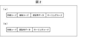
- FIG. 3 is a diagram illustrating an example of a data structure of a signal.
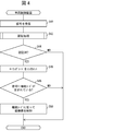
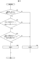
- 4 is a flowchart illustrating a flow of processing of the portable device. It is a flowchart which shows the flow of a process of the said vehicle control apparatus. It is a flowchart which shows the flow of the authentication processing in the said vehicle control apparatus.
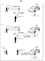
- FIG. 4 is a sequence diagram illustrating a flow of signal transmission and reception between the portable device and the vehicle control device. It is a figure showing the way of the roll jam when the user locks the door of the car.
- a control system includes at least a vehicle load, a vehicle control device that controls the vehicle load, and a portable device that wirelessly communicates with the vehicle control device, and instructs (requests) the vehicle control device. And a portable device for transmitting the information.
- the control system according to the present invention is applicable to, for example, a keyless entry (RKE) system of a car lock mechanism.
- RKE keyless entry
- a so-called roll jam has occurred in which the operation of the RKE system is reversed and the locking mechanism of a vehicle corresponding to the RKE system is unlocked illegally.
- FIG. 7 is a view showing a roll jam method when a user locks a car door.
- FIG. 7A illustrates the operation of each device when the user stops the vehicle at a parking lot or the like and then operates the remote control once toward the vehicle.
- the remote controller transmits a keyless signal (first time) to the vehicle (more precisely, a vehicle control device inside the vehicle). A criminal trying to steal the vehicle illegally obtains the first keyless signal using an external tool.
- the external tool interferes with the reception of the keyless signal in the vehicle control device by transmitting the jamming radio wave. Further, the external tool acquires and stores the keyless signal together with the emission of the jamming radio wave. As a result, the first keyless signal is stored in the external tool. Since the vehicle control device has not received the keyless signal, the vehicle is naturally not locked. Hence, since the illegal acquisition of the keyless signal is not apparent, the user does not notice that the keyless signal has been illegally acquired, and operates the remote controller again to try locking the vehicle.
- FIG. 7B shows the operation of each device when the user operates the remote controller again.
- the external tool also transmits a jamming radio wave for the second keyless signal and acquires the second keyless signal. Then, the external tool transmits the first keyless signal acquired last time to the vehicle instead of the second keyless signal.
- the vehicle control device receives the first keyless signal. Since the keyless signal itself is a legitimate signal originally transmitted from the portable device 1, the vehicle control device authenticates the keyless signal and locks the vehicle according to the keyless signal. Thereby, it looks as if the vehicle has been locked in response to the second user's remote control operation. Therefore, the user leaves the vehicle without noticing that the second keyless signal has been illegally acquired.
- FIG. 7 shows the operation of each device after the user has left the vicinity of the vehicle.
- the criminal performs a predetermined operation on the external tool (for example, pressing a button for instructing keyless signal transmission).
- the external tool Upon receiving the operation, the external tool transmits the stored second keyless signal.
- the vehicle control device receives the second keyless signal and unlocks the lock mechanism. Thereby, the key of the vehicle can be unlocked without the user.
- the control system according to the present invention is particularly effective in preventing unauthorized unlocking and locking of the vehicle due to the roll jam.
- the configuration and processing of various devices according to an embodiment of the present invention will be described with reference to FIGS.
- FIG. 1 is a block diagram showing a main configuration of the portable device 1 and the vehicle control device 2 included in the control system 500 according to the present embodiment.
- FIG. 2 also shows the lock mechanism 3 as an example of the vehicle load.
- the portable device 1 is a device that transmits a signal to the vehicle control device 2.
- Specific examples of the portable device 1 include a terminal device that can be carried by a user, such as a remote controller, a mobile phone, a smartphone, and a tablet PC (personal computer).
- the portable device 1 includes a control unit 10, an input unit 20, a storage unit 30, and a communication unit 40.
- the input unit 20 receives a user's input operation.
- the input unit 20 is realized by, for example, a physical button of the portable device 1 or a touch panel.
- the portable device 1 may include a plurality of input units 20 according to the instruction content to the vehicle control device 2.
- the portable device 1 may include, as the input unit 20, a lock button that is a button for instructing locking and an unlock button that is a button for instructing unlocking.
- the input unit 20 transmits a user's input operation to the control unit 10.
- the storage unit 30 stores various data used by the portable device 1.
- the storage unit 30 stores at least a rolling code (identification code) 31.
- the rolling code 31 includes a numerical value or a code string selected from a plurality of code strings in an order.
- the rolling code 31 may be a numerical value having a predetermined number of digits, or a code string selected from a list (code string list) in which a predetermined number of code strings composed of numbers, symbols, and characters are ordered. There may be. Further, the rolling code 31 may be a code generated by adding the numerical value or the code string to a random code generated at random. When the rolling code 31 includes the code string, the storage unit 30 also stores the code string list.
- the storage unit 30 may store data necessary for generating various signals in addition to the rolling code 31.
- the storage unit 30 may store synchronization codes, function codes, and authentication data of various signals. These data will be described later in detail.
- the control unit 10 controls the portable device 1 overall.
- the control unit 10 specifies an instruction content (for example, a locking instruction or an unlocking instruction) with respect to the user's input operation transmitted from the input unit 20, and controls each unit of the portable device 1 according to the instruction.
- the control unit 10 includes a first signal generation unit (first transmission unit) 11, a second signal generation unit (second transmission unit) 12, and a code update unit (identification code change unit) 13.
- the first signal generator 11 generates and transmits a first signal.
- the control unit 10 instructs the first signal generation unit 11 to generate a signal.
- the first signal generation unit 11 reads out the rolling code 31 and various data necessary for generating the first signal from the storage unit 30, and generates a first signal.
- the first signal generation unit 11 transmits the generated signal to the vehicle control device 2 via the communication unit 40.
- the code updating unit 13 updates the numerical value or code string of the rolling code 31.
- the code update unit 13 updates the rolling code 31 (or a partial numerical value or code string of the rolling code 31) with A larger numerical value or the order in the code string list changes to a later code string.
- changing the numerical value or code string of the rolling code (the rolling code 31 or a rolling code 71 to be described later) to a larger numerical value or changing the order in the code string list to a later code string is referred to as “increase (increase) the rolling code. Do ".
- the code updating unit 13 increments the rolling code 31 each time the first signal generation unit 11 transmits the first signal, and each time the second signal generation unit 12 transmits the second signal.
- the code updating unit 13 notifies the second signal generating unit 12 that the increment is completed.
- the second signal generation unit 12 generates and transmits a second signal.
- the second signal generating unit 12 transmits the rolling code 31 (that is, the rolling code after the increment) from the storage unit 30 and various data necessary for generating the second signal. Is read to generate a second signal.
- the second signal generation unit 12 transmits the generated second signal to the vehicle control device 2 via the communication unit 40.
- the second signal generation unit 12 repeats generation and transmission of the second signal a predetermined number of times.
- the communication unit 40 transmits the first signal received from the first signal generation unit 11 and the second signal received from the second signal generation unit 12 to the vehicle control device 2 by wireless communication.
- the band and system of the wireless communication are not particularly limited, but the wireless communication can be performed in, for example, a UHF (Ultra High Frequency) band.
- FIG. 2 is a diagram illustrating an example of a data structure of a signal.
- FIG. 2A shows an example of the data structure of the first signal.
- FIG. 2B shows an example of the data structure of the second signal.
- the first signal includes, for example, a synchronization code, a function code, authentication data, and a rolling code.
- the second signal includes data other than the function code among various data included in the first signal.
- the synchronization code is a code string for synchronizing communication between the portable device 1 and the vehicle control device 2. In some cases, the detection of the synchronization code triggers the external tool to start transmitting a jamming radio wave and attempting to illegally acquire a keyless signal.
- the function code is a code string indicating a control request (control request) for the portable device 1.
- the external tool may further detect whether or not the function code is included in the keyless signal. For example, if the function code is included in the keyless signal, the transmission of the jamming signal and the attempt to illegally acquire the keyless signal are continued. There may be external tools that keep trying. Examples of the function code include a lock request and an unlock request.
- the authentication data indicates that the portable device 1 is a legitimate portable device, such as the identifier of the portable device 1 (such as the ID of the device) and the result of a cryptographic operation determined between the portable device 1 and the vehicle control device 2. This is data for confirmation.
- the rolling code is a rolling code read from the storage unit 30.
- the vehicle control device 2 is a device that determines whether a signal received from the portable device 1 is correct or not. Further, when the signal determined to be valid includes a function code, the vehicle control device 2 operates according to the function code.
- the vehicle control device 2 according to the present embodiment is an in-vehicle device mounted on the vehicle 100.
- the lock mechanism 3 to be controlled by the vehicle control device 2 is a lock mechanism for a door of the vehicle 100.
- Vehicle control device 2 includes a communication unit 50, a control unit 60, and a storage unit 70.
- the communication unit (receiving unit) 50 receives the first signal and the second signal transmitted by the communication unit 40 of the portable device 1. As will be described in detail later, the communication unit 50 can also receive the first signal and the second signal transmitted by a device other than the portable device 1 (for example, an external tool).
- the control unit 60 controls the vehicle control device 2 overall.
- the control unit 60 includes an authentication unit (correctness determination unit) 61, a code update unit 62, and a lock mechanism control unit (control execution unit) 63.
- the authentication unit 61 determines whether the received signal is a legitimate signal, and if the signal is a legitimate signal, authenticates the signal. Specifically, if the rolling code included in the received signal has a numerical value greater than the rolling code 71 stored in the storage unit 70 or the order of the code sequence is later, the authentication unit 61 , Is determined to be a valid signal. On the other hand, when the rolling code included in the received signal has a numerical value smaller than that of the rolling code 71 or the order of the codes is earlier, the authentication unit 61 determines that the signal is an invalid signal. . The authentication unit 61 notifies the code update unit 62 and the lock mechanism control unit 63 of the determination result (that is, whether or not authentication is possible).
- the code updating unit 62 updates the rolling code 71 in the storage unit 70 when the signal is authenticated. More specifically, the code updating unit 62 rewrites the rolling code 71 with a rolling code included in the authenticated signal. As described above, the rolling code included in the authenticated signal has a numerical value larger than at least the rolling code 71, or the order of the code sequence is later. Therefore, the code updating unit 62 updates the rolling code 71, thereby incrementing the rolling code 71.
- the lock mechanism control unit 63 determines whether or not the function code is included in the authenticated signal, and if the function code is included, controls the lock mechanism 3 according to the function code. For example, when the function code indicates a lock request, the lock mechanism control unit 63 locks the lock mechanism 3. For example, when the function code indicates an unlocking request, the lock mechanism control unit 63 unlocks the lock mechanism 3.
- the storage unit 70 stores various data used by the vehicle control device 2.
- the storage unit 70 stores at least a rolling code (identification code) 71.
- the rolling code 71 has the same format as the rolling code 31.
- the storage unit 70 stores the rolling code (rolling code 31) included in the signal that was previously determined to be valid and authenticated as the rolling code 71.
- the rolling code 71 includes a code string selected from the code string list as in the case of the rolling code 31, the storage unit 70 stores the same code string list as the storage unit 30.
- FIG. 3 is a flowchart showing the flow of the process of the portable device 1.
- FIG. 2 shows the flow of processing when the user performs an input operation (for example, pressing a button) once on the portable device 1.
- first signal generation unit 11 When input unit 20 of portable device 1 receives an input operation by the user (YES in S10), first signal generation unit 11 generates a first signal. The first signal generation unit 11 transmits the generated first signal to the vehicle control device 2 via the communication unit 40 (S12).
- the first signal generation unit 11 notifies the code update unit 13 that the first signal has been transmitted.
- the code update unit 13 increments the rolling code 31 in the storage unit 30 (S14).
- the code updating unit 13 notifies the second signal generation unit 12 that the increment of the rolling code 31 has been completed.
- the second signal generating unit 12 When the second signal generating unit 12 receives the notification from the code updating unit 13, the second signal generating unit 12 counts after the transmission of the first signal in S12 and determines whether the second signal has been transmitted a predetermined number of times (S16). Immediately after the transmission of the first signal, the second signal has not been transmitted (NO in S16). In this case, the second signal generator 12 generates a second signal. The second signal generation unit 12 transmits the generated second signal to the vehicle control device 2 via the communication unit 40 (S18). The second signal generation unit 12 notifies the code update unit 13 that the second signal has been transmitted.
- the code update unit 13 Upon receiving the notification from the second signal generation unit 12, the code update unit 13 increments the rolling code 31 (S20). The code updating unit 13 notifies the second signal generation unit 12 that the increment of the rolling code 31 has been completed.
- the second signal generating unit 12 Upon receiving the notification from the code updating unit 13, the second signal generating unit 12 performs the determination in S16 again.
- the second signal generation unit 12 and the code update unit 13 repeat the processing of S16 to S20 until the second signal is transmitted a predetermined number of times.
- second signal generation unit 12 ends transmission of the second signal, and the process in portable device 1 is completed.
- FIG. 4 is a flowchart showing the flow of the process of the vehicle control device 2.
- FIG. 3 shows the flow of processing when the vehicle control device 2 receives a signal (first signal or second signal) once.
- the authentication unit 61 of the control unit 60 executes an authentication process (S42).
- the code updating unit 62 of the control unit 60 increments the rolling code 71 in the storage unit 70 (S46). Further, the lock mechanism control unit 63 of the control unit 60 determines whether the authenticated signal includes a function code (S48).
- the authenticated signal is the first signal
- the signal includes the function code (YES in S48).
- the lock mechanism control unit 63 controls the lock mechanism according to the function code (S50).
- the authenticated signal is the second signal
- the signal does not include a function code (NO in S48).
- the lock mechanism control unit 63 does not control the lock mechanism 3.
- the vehicle control device 2 does not perform the subsequent processing and ends the processing.
- the received signal is not authenticated (authentication was NG) (NO in S44)
- vehicle control device 2 ends the process without performing the subsequent processes.
- FIG. 5 is a flowchart showing a flow of the authentication process (S42 in FIG. 4) in the vehicle control device 2.
- the authentication unit 61 determines whether the authentication data and the function code of the signal are correct (S60). For example, the authentication unit 61 checks the identifier included in the authentication data, and determines that the authentication code is correct when the identifier is the identifier of the portable device 1 supported by the vehicle control device 2. Further, for example, when the code string of the function code is in a format that can be read and executed by the vehicle control device 2, the authentication unit 61 determines that the function code is correct.
- the authentication unit 61 further stores the rolling code of the received signal in the rolling code 71 stored in the storage unit 70 of its own device (that is, the previous reception code). It is determined whether it is equal to or more than the rolling code included in the signal (S62). If the rolling code of the received signal is equal to or greater than rolling code 71 (YES in S62), authentication unit 61 further determines whether the difference between the rolling code of the received signal and rolling code 71 is equal to or less than a predetermined value. Is determined (S63).
- the authentication unit 61 determines that the received signal is a legitimate signal and authenticates the signal ( Authentication OK, S64).
- the authentication unit 61 determines that the received signal is an invalid signal and does not authenticate the signal (authentication NG, S66).
- FIG. 6 is a sequence diagram showing a flow of signal transmission and reception between the portable device 1 and the vehicle control device 2.
- the rolling code 31 of the portable device 1 starts from a predetermined integer K.
- the rolling code 71 of the vehicle control device 2 starts from K ⁇ 1 which is smaller than the starting value of the rolling code 31 by one.
- the rolling code is also simply referred to as “code”.
- the portable device 1 When the portable device 1 receives a predetermined input operation (S100), it transmits a first signal (rolling code: K) (S102).
- the vehicle control device 2 receives the signal (S104), and performs authentication processing in the authentication unit 61. Since the rolling code of the received signal is K, which is larger than the value of the rolling code 71, the authentication unit 61 sets the signal to authentication OK (S106). Then, the lock mechanism control unit 63 controls locking of the lock mechanism 3 according to the function code of the authenticated first signal (S108).
- the second signal is generated and transmitted a predetermined number of times (in the illustrated example, n times), and the vehicle control device 2 performs an authentication process for each second signal. (S110 to S120). Further, the code updating unit 13 of the portable device 1 increments the rolling code 31 each time a signal is transmitted. Further, the code updating unit 62 of the vehicle control device 2 increments the rolling code 71 every time the signal is authenticated.
- the rolling code 31 after transmitting the second signal n times becomes K + (n + 1).
- the rolling code 71 after receiving and authenticating the second signal n times becomes K + n. Note that, even if the reception of any one of the second signals transmitted n times fails, the rolling code 31 is always a numerical value larger than the rolling code 71. Therefore, the first signal and the second signal transmitted from the portable device 1 do not become authentication NG in a normal operation.
- the time from the transmission of the first signal (S102) to the transmission of the second signal (S110) in the portable device 1 is preferably as short as possible. That is, it is desirable that the portable device 1 according to the present embodiment transmits the first second signal immediately after the transmission of the first signal without delay.
- the time from S102 to S110 is set to be at least shorter than the time during which the user can leave the vicinity of the vehicle 100 after operating the portable device 1.
- the number of times of generation and transmission of the second signal is preferably two or more.
- the vehicle control device 2 may not be able to receive the second signal transmitted for the first time.
- the portable device 1 can cause the vehicle control device 2 to reliably receive the second signal.
- the second signal transmitted for the first time may be interrupted by an external tool or the like.
- the possibility that any of the second signals reaches the vehicle control device 2 and is received can be improved. In other words, the vehicle control device 2 can more reliably receive the second signal.
- the transmission interval of the second signal is preferably short.
- the transmission interval of the second signal is desirably 1 second or less.
- the portable device 1 desirably transmits the second signal continuously after transmitting the first signal.
- the external tool can identify the type of the keyless signal by checking the synchronization code or the like, and can selectively and illegally acquire the keyless signal.
- the external tool has a structure in which one of the first signal and the second signal is selectively illegally acquired.
- the vehicle control device 2 cannot receive the first signal due to the interfering radio wave transmitted by the external tool.
- the vehicle control device 2 can receive the second signal transmitted after the first signal. That is, when the first signal is illegally acquired by the external tool, the order of receiving the first signal and the second signal in the vehicle control device 2 is switched.
- the vehicle control device 2 increments the rolling code 71 in accordance with the received second signal, when the first signal is received later, the rolling code 71 is larger than the rolling code of the received signal (see FIG. NO in S62 of No. 5). Therefore, the vehicle control device 2 determines that the first signal is an incorrect signal and does not authenticate.
- the vehicle control device 2 transmits the first signal transmitted later when the original signal reception order is changed based on the comparison between the rolling code of the received signal and its own rolling code 71. Authentication can be disabled. Thereby, the portable device 1 and the vehicle control device 2 can prevent the vehicle control device 2 from being illegally operated by an external tool.
- the control unit 10 of the portable device 1 determines the number of transmissions of the second signal when the predetermined input operation is performed again before the second signal generation unit 12 finishes transmitting the second signal the predetermined number of times. In addition to the reset, the transmission of the second signal may be terminated halfway (before reaching the predetermined number). Then, after the first signal is transmitted by the first signal generation unit 11, the second signal may be transmitted again a predetermined number of times from the first time.
- the first signal may be transmitted two or more times consecutively, for example, when the user performs an input operation on the portable device 1 continuously.
- the control unit 10 can surely increase the rolling code in the vehicle control device 2 by transmitting the second signal a predetermined number of times after the transmission of the first signal is completed. Therefore, even if one of the first signals is illegally acquired by the external tool, the vehicle control device 2 can prevent the first signal from being authenticated.
- the control system 500 is effective even when the external tool interferes with and obtains both the first signal and the second signal.
- the first second signal is automatically transmitted after the transmission of the first signal. Therefore, when the external tool illegally acquires both the first signal and the second signal, the external tool can stock only the second signal. This is because a general external tool used for roll jam can store only one signal, and when a new signal is illegally acquired, the previously acquired signal is transmitted by the extrusion method and disappears. .
- the portable device 1 is currently transmitting the first signal or the second signal is apparently invisible. Therefore, the user of the external tool cannot specify the timing of ending the trial of illegal acquisition of the signal to the external tool. For this reason, even if the external tool once obtains the first signal, the external tool captures and obtains the second signal thereafter, and cannot retain the first signal in its own memory. As described above, the vehicle control device 2 receives and authenticates the second signal, but since the signal does not include the function code, the lock mechanism 3 does not operate. Therefore, roll jam is not successful.
- the portable device 1 and the vehicle control device 2 can prevent an unauthorized operation of the vehicle control device 2 by the external tool even when the external tool interferes with and illegally obtains a signal regardless of the synchronization code.
- the user operates the portable device 1 when using the vehicle 100.
- the portable device 1 transmits a first signal for unlocking to the vehicle control device 2 of the vehicle 100. If the external tool illegally acquires the first signal (and the second first signal transmitted by the subsequent re-operation), the opportunity for the user of the external tool to illegally unlock the vehicle comes. Usually, this is when the user locks the vehicle after using the unlocked vehicle and then leaves.
- the portable device 1 Since the portable device 1 has transmitted the second signal to the vehicle control device 2 at least once during this time, the rolling code 71 of the vehicle control device 2 is smaller than the rolling code of the signal held by the external tool. growing. Therefore, even if the signal held by the external tool is transmitted to the vehicle control device 2, the signal is not authenticated, so that unauthorized unlocking cannot be performed.
- the function code (unlock request) for unlocking the lock mechanism 3 and the function code (lock request) for locking the lock mechanism 3 are the same.
- the first signal generation unit 11 and the second signal generation unit 12 of the portable device 1 according to the control system 500 create and transmit different function codes depending on whether the lock mechanism 3 is unlocked or locked. You may.
- the method of the roll jam can be used.
- a signal including the function code of the unlock request may be illegally acquired by an external tool.
- the user recognizes that the unlock has not been successful, and operates the portable device 1 again to try to unlock.
- the second signal is also illegally acquired, the vehicle is unlocked while the unlocking request is held in the external tool. Therefore, if the user locks the vehicle after using the unlocked vehicle and then leaves, the user of the external tool can later unlock the vehicle illegally.
- the vehicle control device 2 since the vehicle control device 2 according to the control system 500 increments the rolling code 71 by the rolling code of the authenticated signal, even if a signal including a small rolling code is received later, the signal is not authenticated. Therefore, even if the signal including the unlock request is illegally acquired as described above, it is possible to prevent the vehicle control device 2 from being illegally operated.
- the applications of the vehicle control device 2 and the lock mechanism 3 are not limited to the above-described embodiment.
- the vehicle control device 2 and the lock mechanism 3 need not be in-vehicle devices.
- the lock mechanism 3 may be a lock mechanism for a building door.
- a mechanism for controlling on and off of the power of the electronic device may be used.
- the vehicle control device 2 may be a device that controls these mechanisms.
- the vehicle control device 2 may control a vehicle load other than the lock mechanism 3.
- the vehicle control device 2 may control a door opening / closing mechanism of the vehicle.
- the function code included in the first signal includes a request for a control operation for opening or closing the door.
- the vehicle control device 2 may control the operation and stop of the engine of the vehicle.
- the function code included in the first signal includes a request for a control operation for operating or stopping the engine.
- the vehicle control device 2 may control turning on and off of the welcome light of the vehicle.
- the function code included in the first signal includes a request for a control operation for turning on or off the welcome light.
- the received signal is valid based on a numerical value or an identification code (rolling code) including a code sequence selected from a plurality of code sequences in a predetermined order.
- a portable device that transmits a signal to a vehicle control device (vehicle control device 2) that determines whether or not the vehicle control device performs predetermined control according to a control request (function code) included in a legitimate signal.
- a first transmission unit (first signal generation unit 11) that transmits a first signal including the identification code and the control request to the vehicle control device in response to a user's input operation;
- a second transmission unit (second signal generation unit 12) configured to transmit a second signal including the identification code but not including the control request to the vehicle control device after the transmission unit transmits the first signal;
- An identification code changing unit (code updating unit 13) that changes the numerical value to a large numerical value or changes the code sequence to a code sequence in a later order every time the second signal is transmitted.
- External tools for illegally acquiring signals including control requests have been known.
- the user of the external tool sees the user's intention to get off and get on the vehicle, and operates the external tool to try to acquire a signal illegally.
- the user was able to illegally operate the vehicle control device by transmitting the signal that the external tool illegally acquired to the vehicle control device later.
- the portable device each time the portable device transmits a signal, the portable device changes the identification code of the signal to a larger numerical value or a later identification code.
- the identification code indicates the transmission order of the signal from the portable device.
- the portable device automatically transmits the second signal after transmitting the first signal.
- the second signal is illegally acquired by an external tool
- the second signal does not include a control request. Therefore, even if the illegally acquired second signal is retransmitted to the vehicle control device, the vehicle control device does not operate. Therefore, according to the configuration, it is possible to prevent the vehicle control device from being illegally operated by the external tool.
- the predetermined control may include transmitting the second signal two or more times continuously after the first transmission unit transmits the first signal. You may.
- the vehicle control device can more reliably receive the second signal.
- the predetermined control is to unlock or lock a lock mechanism of a door of the vehicle, and the first transmission unit controls the lock mechanism.
- the first signal including an unlocking or locking request as the control request may be transmitted.
- a vehicle control device includes a receiving unit (communication unit 40) for receiving a signal from the portable device according to any one of the first to third aspects, and a signal received by the receiving unit.
- a right / wrong determining unit (authenticating unit 61) for determining whether or not the first signal is valid, and a predetermined signal in response to the control request included in the first signal when the right / wrong determining unit determines that the first signal is valid.
- a control execution unit (lock mechanism control unit 63) for performing control, wherein the correctness determination unit determines whether the identification code included in the signal received by the reception unit is valid last time. If the numerical value is smaller than the included identification code or the code sequence is an identification code whose order is earlier, it is determined that the received signal is an incorrect signal. According to the configuration, the same effect as that of the portable device according to the first aspect is obtained.
- a control system (control system 500) includes a portable device (portable device 1) according to any one of the first to third aspects and a vehicle control device (vehicle) according to the fourth aspect.
- a control device 2) and a vehicle load (lock mechanism 3) controlled by the vehicle control device are included. According to the configuration, the same effect as that of the portable device according to the first aspect is obtained.
- control blocks (particularly, the control unit 10 and the control unit 60) of the portable device 1 and the vehicle control device 2 may be realized by a logic circuit (hardware) formed on an integrated circuit (IC chip) or the like, or by software. It may be realized.
- the portable device 1 and the vehicle control device 2 include a computer that executes instructions of a program that is software for realizing each function.
- the computer includes, for example, one or more processors and a computer-readable recording medium storing the program. Then, in the computer, the object of the present invention is achieved when the processor reads the program from the recording medium and executes the program.
- a CPU Central Processing Unit
- the recording medium in addition to “temporary tangible medium”, for example, ROM (Read Only Memory), tape, disk, card, semiconductor memory, programmable logic circuit, and the like can be used. Further, a RAM (Random Access Memory) for expanding the program may be further provided.
- the program may be supplied to the computer via an arbitrary transmission medium (a communication network, a broadcast wave, or the like) capable of transmitting the program.
- a transmission medium a communication network, a broadcast wave, or the like
- One embodiment of the present invention can also be realized in the form of a data signal embedded in a carrier wave, in which the program is embodied by electronic transmission.
- 1 ⁇ portable device 10 ⁇ control unit, 11 ⁇ first signal generation unit (first transmission unit), 12 ⁇ second signal generation unit (second transmission unit), 13 ⁇ code update unit (identification code change unit), 20 ⁇ input unit, 30 Storage unit, 31 rolling code (identification code), 40 communication unit, 2 vehicle control device, 50 communication unit (receiving unit), 60 control unit, 61 authentication unit (authority determination unit), 62 code updating unit (control execution unit) , 63 locking mechanism control unit, 70 locking unit, 71 rolling code (identification code), 3 locking mechanism (vehicle load), 100 vehicle, 500 control system
Landscapes
- Engineering & Computer Science (AREA)
- Mechanical Engineering (AREA)
- Lock And Its Accessories (AREA)
Abstract
外部ツールによって車両制御装置が不正動作させられることを防ぐ。携帯機(1)は、ユーザの入力操作に応じて、ローリングコード(31)と機能コードとを含む第1信号を車両制御装置(2)へ送信する第1信号生成部(11)と、第1信号を送信した後に、ローリングコード(31)を含むが機能コードを含まない第2信号を車両制御装置(2)へ送信する第2信号生成部(12)と、第1信号を送信する度、および、第2信号を送信する度に、機能コードの数値を大きい数値に変更する、または、機能コードの符号列を順序が後の符号列に変更するコード更新部(13)と、を備える。
Description
本発明は、正当な信号に含まれる制御要求に従って動作する車両制御装置に対して信号を送信する携帯機等に関する。
従来から、キーレスエントリー(RKE)システムを搭載した車両が開発されている。キーレスエントリーシステムは、ユーザの所持するリモコンと、車両制御装置と、車両の錠機構とから成る。車両制御装置はリモコンからの信号(キーレス信号)を受け付け、該信号に含まれている要求に従って、錠機構を制御(解錠または施錠)する。キーレス信号には認証用の種々のコードが含まれており、車両制御装置は、該コードに基づいて正当であると認証した信号の解錠要求または施錠要求のみに従って動作する。
ところが、近年、RKEシステムを搭載した車両の錠機構を不正に解錠し、該車両を盗むという犯罪(所謂、「ロールジャム」)が発生している。そして、ロールジャム対策として、種々の技術が開発されている。
例えば、特許文献1には、車載機におけるコードの照合(第1照合)時に、携帯機側ローリングコードを第1の値だけ更新し、第1照合完了後のエンジン始動時の第2照合でも照合が成立した場合に、第1の値より大きな第2の値だけ更新する技術が記載されている。また、特許文献2には、RKEシステムに係る制御信号の出力とは異なる要因によりドアロック装置の解錠や施錠が実行された場合、車両制御装置の保持しているコードの順番を先に進めることにより、後から不正取得された認証情報を受信した場合に、該情報を正当でないと判定する技術が記載されている。
ロールジャムによるキーレス信号の不正取得は、ユーザがリモコンを操作するあらゆる場面で起こり得る。ところが、前記特許文献1および2に記載の発明は、ロールジャムが起こり得る場面のうち、限定的な場面でのみ有効な防止策である。
例えば、特許文献1に記載の発明では、RKEシステムだけで車両の解錠および施錠を行う場合、ロールジャムを防止できないという問題がある。特許文献1に記載の発明では、RKEシステムを利用して施錠した後、物理キーでの解錠またはオートロックによる施錠等、RKEシステムとは別の解錠または施錠の制御が行われることが前提となっているからである。
また例えば、特許文献2に記載の発明では、ユーザが車のドアを施錠する場面でのロールジャムには対応できないという問題がある。特許文献2に記載の発明は、車両の解錠後、ブレーキペダルの踏込等をトリガとして第2照合を行い、該第2照合が成立した時に、キーレス信号に含まれるコードを更新するからである。
本発明の一態様は、前記問題点に鑑みたものであり、外部ツールによって車両制御装置が不正動作させられることを防ぐことが可能な携帯機等を実現することを目的とする。
前記の課題を解決するために、本発明の一態様に係る携帯機は、数値、または、順序が定められた複数の符号列から選択される符号列を含む識別コードに基づいて受信信号が正当か否かを判定する車両制御装置であり、正当な信号に含まれる制御要求に従って所定の制御を行う車両制御装置に対して、信号を送信する携帯機であって、ユーザの入力操作に応じて、前記識別コードと、前記制御要求と、を含む第1信号を前記車両制御装置へ送信する第1送信部と、前記第1送信部が前記第1信号を送信した後に、前記識別コードを含むが前記制御要求を含まない第2信号を前記車両制御装置へ送信する第2送信部と、前記第1信号を送信する度、および、前記第2信号を送信する度に、前記数値を大きい数値に変更する、または、前記符号列を前記順序が後の符号列に変更する、識別コード変更部と、を備える。
本発明の一態様によれば、外部ツールによって車両制御装置が不正動作させられることを防ぐことができる。
〔実施形態1〕
(制御システムの概要)
以下、本発明の一実施形態について、詳細に説明する。本発明に係る制御システムは、少なくとも、車両負荷と、該車両負荷を制御する車両制御装置と、該車両制御装置と無線通信する携帯機であって、該車両制御装置に対して指示(要求)を送信する携帯機と、を含む。
(制御システムの概要)
以下、本発明の一実施形態について、詳細に説明する。本発明に係る制御システムは、少なくとも、車両負荷と、該車両負荷を制御する車両制御装置と、該車両制御装置と無線通信する携帯機であって、該車両制御装置に対して指示(要求)を送信する携帯機と、を含む。
本発明に係る制御システムは、例えば、車の錠機構のキーレスエントリー(RKE)システムに適用可能である。近年、RKEシステムの動作を逆手にとって、RKEシステムに対応した車両の錠機構を不正に解錠する、所謂ロールジャムという犯罪が発生している。
図7は、ユーザが車のドアを施錠する場合のロールジャムの手口を示す図である。図7の(a)は、ユーザが車両を駐車場等に停めた後、リモコンを該車両に向けて1回操作した場合の各装置の動作を示している。ユーザのリモコン操作に応じて、リモコンは車両(より厳密には、車両内部の車両制御装置)に対して、キーレス信号(1回目)を送信する。車両を盗もうとする犯罪者は、外部ツールを用いて、この1回目のキーレス信号を不正取得する。
より詳しくは、外部ツールは、妨害電波を発信することで、車両制御装置におけるキーレス信号の受信を妨害する。また、外部ツールは妨害電波の発信とともに、該キーレス信号を取得および記憶する。これにより、外部ツールには1回目のキーレス信号が記憶された状態となる。車両制御装置はキーレス信号を受信していないため、当然ながら、車両は施錠されない。見かけ上ではキーレス信号の不正取得は分からないため、ユーザはキーレス信号が不正取得されたことには気づかず、再度リモコンを操作し車両の施錠を試みる。
図7の(b)は、ユーザがリモコンを再度操作した場合の各装置の動作を示している。図示の通り、外部ツールは2回目のキーレス信号についても妨害電波の発信と、該2回目のキーレス信号の取得とを行う。そして、外部ツールは、前回取得した1回目のキーレス信号を、2回目のキーレス信号の代わりに車両に送信する。車両制御装置は、該1回目のキーレス信号を受信する。このキーレス信号自体は、元々携帯機1から発信された正規の信号であるため、車両制御装置は該キーレス信号を認証して、該キーレス信号に従って車両を施錠する。これにより、見かけ上は、2回目のユーザのリモコン操作に応じて車両が施錠されたように見える。したがって、ユーザは2回目のキーレス信号が不正取得されたことにも気づかずに、車両から離れる。
図7の(c)は、ユーザが車両の近傍から立ち去った後の、各装置の動作を示している。ユーザが立ち去った後、犯罪者は外部ツールに対し所定の操作(例えば、キーレス信号送信を指示するボタンの押下)を行う。外部ツールは該操作を受け付けると、記憶していた2回目のキーレス信号を送信する。車両制御装置は該2回目のキーレス信号を受信し、錠機構を解錠する。これにより、ユーザの居ない所で、車両の鍵を不正解錠することができる。
本発明に係る制御システムは、特にこのロールジャムによる車両の不正解錠および施錠の防止に有効である。以下、図1~6を用いて、本発明の一実施形態に係る、各種装置の構成および処理について説明する。
(要部構成)
図1は、本実施形態に係る制御システム500に含まれる携帯機1および車両制御装置2の要部構成を示すブロック図である。同図では、車両負荷の一例として、錠機構3を併せて図示している。
図1は、本実施形態に係る制御システム500に含まれる携帯機1および車両制御装置2の要部構成を示すブロック図である。同図では、車両負荷の一例として、錠機構3を併せて図示している。
(携帯機1の要部構成)
携帯機1は、車両制御装置2に信号を送信する装置である。携帯機1の具体例としては、例えばリモコン、携帯電話、スマートフォン、タブレットPC(personal computer)等の、ユーザが持ち運び可能な端末装置が挙げられる。携帯機1は、制御部10、入力部20、記憶部30、および通信部40を備えている。
携帯機1は、車両制御装置2に信号を送信する装置である。携帯機1の具体例としては、例えばリモコン、携帯電話、スマートフォン、タブレットPC(personal computer)等の、ユーザが持ち運び可能な端末装置が挙げられる。携帯機1は、制御部10、入力部20、記憶部30、および通信部40を備えている。
入力部20は、ユーザの入力操作を受け付ける。入力部20は例えば携帯機1の物理ボタンまたはタッチパネルで実現される。携帯機1は、車両制御装置2に対する指示内容に応じて複数の入力部20を備えていてもよい。例えば、携帯機1は入力部20として、施錠を指示するためのボタンであるロックボタンと、解錠を指示するためのボタンであるアンロックボタンとを備えていてもよい。入力部20はユーザの入力操作を制御部10に伝える。
記憶部30は、携帯機1が使用する各種データを記憶する。記憶部30は少なくとも、ローリングコード(識別コード)31を記憶している。ローリングコード31は、数値、または、順序が定められた複数の符号列から選択される符号列を含む。
例えば、ローリングコード31は所定桁数の数値であってもよいし、数字、記号、および文字から構成される所定数の符号列に順序付けをしたリスト(符号列リスト)から選択される符号列であってもよい。また、ローリングコード31はランダム生成されるランダムコードに、前記数値または前記符号列を付したものであってもよい。なお、ローリングコード31が前記符号列を含む場合、記憶部30は該符号列リストも記憶している。
記憶部30は、ローリングコード31の他に、各種信号を生成するために必要なデータを記憶していてもよい。例えば、記憶部30は各種信号の同期コード、機能コード、および認証用データを記憶していてもよい。これらのデータについては、後で詳述する。
制御部10は、携帯機1を統括的に制御する。制御部10は入力部20から伝えられたユーザの入力操作について、指示内容(例えば、施錠の指示か解錠の指示か)を特定し、該指示に応じて携帯機1の各部を制御する。制御部10は、第1信号生成部(第1送信部)11、第2信号生成部(第2送信部)12、およびコード更新部(識別コード変更部)13を含む。
第1信号生成部11は、第1信号を生成して送信する。制御部10が入力部20から伝えられた入力操作が所定の入力操作(例えば、所定のボタンの押下)であった場合、制御部10は第1信号生成部11に信号の生成を指示する。第1信号生成部11は、記憶部30からローリングコード31と、第1信号の生成に必要な各種データとを読み出して、第1信号を生成する。第1信号生成部11は生成した信号を、通信部40を介して車両制御装置2に送信する。
コード更新部13は、ローリングコード31の数値または符号列を更新する。コード更新部13は、第1信号生成部11または第2信号生成部12から信号を送信した旨を通知されると、ローリングコード31(またはローリングコード31の一部の数値または符号列)を、大きい数値、または、符号列リストにおける順序が後の符号列に変更する。以降、ローリングコード(ローリングコード31または後述するローリングコード71)の数値または符号列を大きい数値、または、符号列リストにおける順序が後の符号列に変更することを、「ローリングコードをインクリメント(増加)する」と称する。
換言すると、コード更新部13は、第1信号生成部11が第1信号を送信する度、および、第2信号生成部12が第2信号を送信する度に、ローリングコード31をインクリメントする。コード更新部13はローリングコード31のインクリメントが完了すると、該インクリメントが完了した旨を第2信号生成部12に通知する。
第2信号生成部12は、第2信号を生成して送信する。第2信号生成部12は、コード更新部13からインクリメントの完了を通知されると、記憶部30からローリングコード31(すなわち、インクリメント後のローリングコード)と、第2信号の生成に必要な各種データとを読み出して、第2信号を生成する。第2信号生成部12は生成した第2信号を、通信部40を介して車両制御装置2に送信する。第2信号生成部12は、第2信号の生成および送信を、所定回数だけ繰り返す。
通信部40は、第1信号生成部11から受信した第1信号、および第2信号生成部12から受信した第2信号を、無線通信で車両制御装置2に送信する。無線通信の帯域および方式は特に限定しないが、例えばUHF(Ultra High Frequency)帯の帯域で無線通信を行うことができる。
(信号のデータ構成)
次に、第1信号および第2信号のデータ構造について図2を用いて説明する。図2は、信号のデータ構造の一例を示す図である。図2の(a)は第1信号のデータ構造の一例を示している。一方、図2の(b)は第2信号のデータ構造の一例を示している。
次に、第1信号および第2信号のデータ構造について図2を用いて説明する。図2は、信号のデータ構造の一例を示す図である。図2の(a)は第1信号のデータ構造の一例を示している。一方、図2の(b)は第2信号のデータ構造の一例を示している。
第1信号は、例えば、同期コードと、機能コードと、認証用データと、ローリングコードと、を含む。一方、第2信号は、第1信号に含まれる各種データのうち、機能コード以外のデータを含む。
同期コードは、携帯機1と車両制御装置2との間で通信の同期をとるための符号列である。外部ツールは同期コードを検知したことをトリガとして妨害電波の発信、およびキーレス信号の不正取得の試行を開始する場合がある。機能コードは、携帯機1に対する制御のリクエスト(制御要求)を示す符号列である。
外部ツールは、キーレス信号の同期コードを検知してから、さらに該キーレス信号に機能コードが含まれているか否かを検知する場合がある。例えば、キーレス信号に機能コードが含まれている場合は妨害電波の発信およびキーレス信号の不正取得の試行を継続し、機能コードが含まれていない場合は妨害電波の発信およびキーレス信号の不正取得の試行を継続する外部ツールが存在し得る。機能コードの一例として、施錠要求および解錠要求等が挙げられる。認証用データは、携帯機1の識別子(装置のID等)、および携帯機1と車両制御装置2との間で取り決められる暗号の演算結果等、携帯機1が正規の携帯機であることを確認するためのデータである。ローリングコードは、記憶部30から読み出されたローリングコードである。
(車両制御装置2の要部構成)
車両制御装置2は、携帯機1からの受信信号の正否を判定する装置である。また、車両制御装置2は、正当であると判定した信号に機能コードが含まれている場合、該機能コードに従って動作する。本実施形態における車両制御装置2は、車両100に搭載された車載装置である。また、車両制御装置2が制御する対象である錠機構3は、車両100のドアの錠機構である。車両制御装置2は、通信部50と、制御部60と、記憶部70とを含む。
車両制御装置2は、携帯機1からの受信信号の正否を判定する装置である。また、車両制御装置2は、正当であると判定した信号に機能コードが含まれている場合、該機能コードに従って動作する。本実施形態における車両制御装置2は、車両100に搭載された車載装置である。また、車両制御装置2が制御する対象である錠機構3は、車両100のドアの錠機構である。車両制御装置2は、通信部50と、制御部60と、記憶部70とを含む。
通信部(受信部)50は、携帯機1の通信部40が送信した第1信号および第2信号を受信する。詳しくは後述するが、通信部50は、携帯機1以外(例えば、外部ツール)が送信した第1信号および第2信号も受信し得る。
制御部60は、車両制御装置2を統括的に制御する。制御部60は、認証部(正否判定部)61、コード更新部62、および錠機構制御部(制御実行部)63を含む。
認証部61は、受信した信号が正当な信号であるか否かを判定し、正当な信号である場合、該信号を認証する。具体的には、受信した信号に含まれているローリングコードが、記憶部70に記憶されているローリングコード71よりも数値が大きい、または符号列の順序が後であった場合、認証部61は、該信号は正当な信号であると判定する。一方、受信した信号に含まれているローリングコードが、ローリングコード71よりも数値が小さい、または符号の順序が前であった場合、認証部61は、該信号は不正な信号であると判定する。認証部61は判定結果(すなわち、認証可否)をコード更新部62および錠機構制御部63に通知する。
コード更新部62は、信号が認証された場合、記憶部70のローリングコード71を更新する。より具体的には、コード更新部62は、ローリングコード71を、認証された信号に含まれているローリングコードに書き替える。上述のように、認証された信号に含まれるローリングコードは、少なくともローリングコード71よりも数値が大きい、または符号列の順序が後である。したがって、コード更新部62は、ローリングコード71を更新することで、ローリングコード71をインクリメントする。
錠機構制御部63は、認証された信号に機能コードが含まれているか否かを判定し、機能コードが含まれている場合、該機能コードに従って錠機構3を制御する。例えば、機能コードが施錠要求を示す場合、錠機構制御部63は錠機構3を施錠させる。また例えば、機能コードが解錠要求を示す場合、錠機構制御部63は錠機構3を解錠させる。
記憶部70は、車両制御装置2が使用する各種データを記憶する。記憶部70は少なくともローリングコード(識別コード)71を記憶している。ローリングコード71は、ローリングコード31と同じ形式を有する。記憶部70には、前回正当と判定されて認証された信号に含まれていたローリングコード(ローリングコード31)が、ローリングコード71として記憶される。なお、ローリングコード71がローリングコード31と同様に符号列リストから選択される符号列を含んでいる場合、記憶部70は、記憶部30と同じ符号列リストを記憶している。
(携帯機の処理の流れ)
図3は、携帯機1の処理の流れを示すフローチャートである。同図では、ユーザが携帯機1に対して1回入力操作(例えば、ボタンの押下)が行われた場合の処理の流れを示している。携帯機1の入力部20がユーザの入力操作を受け付けると(S10でYES)、第1信号生成部11は第1信号を生成する。第1信号生成部11は生成した第1信号を、通信部40を介して車両制御装置2へ送信する(S12)。
図3は、携帯機1の処理の流れを示すフローチャートである。同図では、ユーザが携帯機1に対して1回入力操作(例えば、ボタンの押下)が行われた場合の処理の流れを示している。携帯機1の入力部20がユーザの入力操作を受け付けると(S10でYES)、第1信号生成部11は第1信号を生成する。第1信号生成部11は生成した第1信号を、通信部40を介して車両制御装置2へ送信する(S12)。
第1信号生成部11は、第1信号を送信した旨をコード更新部13に通知する。コード更新部13は第1信号生成部11からの通知を受けると、記憶部30のローリングコード31をインクリメントする(S14)。コード更新部13は、ローリングコード31のインクリメントが完了した旨を第2信号生成部12に通知する。
第2信号生成部12はコード更新部13からの通知を受けると、S12における第1信号の送信後から数えて、第2信号を所定回数送信したか否かを判定する(S16)。第1信号の送信直後は、第2信号は未送信である(S16でNO)。この場合、第2信号生成部12は第2信号を生成する。第2信号生成部12は生成した第2信号を、通信部40を介して車両制御装置2へ送信する(S18)。第2信号生成部12は、第2信号を送信した旨をコード更新部13に通知する。
コード更新部13は、第2信号生成部12からの通知を受けると、ローリングコード31をインクリメントする(S20)。コード更新部13は、ローリングコード31のインクリメントが完了した旨を第2信号生成部12に通知する。
第2信号生成部12はコード更新部13からの通知を受けると、再びS16の判定を行う。以下、第2信号生成部12およびコード更新部13は、第2信号を所定回数送信するまで、S16~S20の処理を繰り返す。第2信号を所定回数送信した場合(S16でYES)、第2信号生成部12は第2信号の送信を終了し、携帯機1における処理が完了する。
(車両制御装置の処理の流れ)
図4は、車両制御装置2の処理の流れを示すフローチャートである。同図では、車両制御装置2が1回信号(第1信号または第2信号)を受信した場合の処理の流れを示している。車両制御装置2の通信部50が信号を受信すると(S40)、制御部60の認証部61は、認証処理を実行する(S42)。
図4は、車両制御装置2の処理の流れを示すフローチャートである。同図では、車両制御装置2が1回信号(第1信号または第2信号)を受信した場合の処理の流れを示している。車両制御装置2の通信部50が信号を受信すると(S40)、制御部60の認証部61は、認証処理を実行する(S42)。
認証処理の結果、受信した信号が認証された(認証OKであった)場合(S44でYES)、制御部60のコード更新部62は、記憶部70のローリングコード71をインクリメントする(S46)。また、制御部60の錠機構制御部63は、認証された信号に、機能コードが含まれているか否かを判定する(S48)。
認証された信号が第1信号である場合、該信号には機能コードが含まれている(S48でYES)。この場合、錠機構制御部63は、該機能コードに従って錠機構を制御する(S50)。一方、認証された信号が第2信号である場合、該信号には機能コードが含まれていない(S48でNO)。この場合、錠機構制御部63は錠機構3の制御を行わない。また、車両制御装置2は以降の処理を行わず、処理を終了する。また、受信した信号が認証されなかった(認証NGであった)場合も(S44でNO)、車両制御装置2は以降の処理を行わず、処理を終了する。
(認証処理)
図5は、車両制御装置2における認証処理(図4におけるS42)の流れを示すフローチャートである。通信部50が信号を受信すると、認証部61は、該信号の認証用データおよび機能コードが正しいか否かを判定する(S60)。例えば、認証部61は、認証用データに含まれる識別子を確認し、該識別子が、車両制御装置2が対応している携帯機1の識別子である場合に、認証用コードが正しいと判定する。また例えば、認証部61は、機能コードの符号列が、車両制御装置2が読み取りおよび実行可能な形式である場合、機能コードが正しいと判定する。
図5は、車両制御装置2における認証処理(図4におけるS42)の流れを示すフローチャートである。通信部50が信号を受信すると、認証部61は、該信号の認証用データおよび機能コードが正しいか否かを判定する(S60)。例えば、認証部61は、認証用データに含まれる識別子を確認し、該識別子が、車両制御装置2が対応している携帯機1の識別子である場合に、認証用コードが正しいと判定する。また例えば、認証部61は、機能コードの符号列が、車両制御装置2が読み取りおよび実行可能な形式である場合、機能コードが正しいと判定する。
信号の認証用データおよび機能コードが正しい場合(S60でYES)、認証部61はさらに、受信した信号のローリングコードが、自装置の記憶部70に記憶しているローリングコード71(すなわち、前回受信した信号に含まれていたローリングコード)以上か否かを判定する(S62)。受信した信号のローリングコードが、ローリングコード71以上である場合(S62でYES)、認証部61はさらに、受信した信号のローリングコードと、ローリングコード71との差が、所定値以下であるか否かを判定する(S63)。受信した信号のローリングコードと、ローリングコード71との差が所定値以下である場合(S63でYES)、認証部61は受信した信号が正当な信号であると判定し、該信号を認証する(認証OK、S64)。
一方、信号の認証用データおよび機能コードが正しくない場合(S60でNO)、受信した信号のローリングコードがローリングコード71より小さい場合(S62でNO)、または、受信した信号のローリングコードと、ローリングコード71との差が所定値よりも大きい場合(S63でNO)、認証部61は受信した信号が不当な信号であると判定して、該信号を認証しない(認証NG、S66)。
(信号の送受信とローリングコードの更新)
図6は、携帯機1と車両制御装置2との信号の送受信の流れを示すシーケンス図である。以降のシーケンス図では、携帯機1のローリングコード31は所定の整数Kから開始することとする。また、以降のシーケンス図では、車両制御装置2のローリングコード71は、ローリングコード31の開始値よりも1小さいK-1から開始することとする。また、以降のシーケンス図では、ローリングコードを単に「コード」とも表記する。
図6は、携帯機1と車両制御装置2との信号の送受信の流れを示すシーケンス図である。以降のシーケンス図では、携帯機1のローリングコード31は所定の整数Kから開始することとする。また、以降のシーケンス図では、車両制御装置2のローリングコード71は、ローリングコード31の開始値よりも1小さいK-1から開始することとする。また、以降のシーケンス図では、ローリングコードを単に「コード」とも表記する。
携帯機1は所定の入力操作を受け付けると(S100)、第1信号(ローリングコード:K)を送信する(S102)。車両制御装置2は該信号を受信し(S104)、認証部61において認証処理を行う。受信した信号のローリングコードはKであり、ローリングコード71の値よりも大きいため、認証部61は該信号を認証OKとする(S106)。そして、錠機構制御部63は認証された第1信号の機能コードに従って、錠機構3の施錠を制御する(S108)。
ところで、携帯機1では、第1信号の送信後に、第2信号が所定回数(図示の例では、n回)だけ生成されて送信され、車両制御装置2は各第2信号について認証処理を行う(S110~S120)。また、携帯機1のコード更新部13は信号を送信する度にローリングコード31をインクリメントする。また、車両制御装置2のコード更新部62は信号が認証される度に、ローリングコード71をインクリメントする。
したがって、第2信号をn回送信した後のローリングコード31はK+(n+1)となる。また、第2信号をn回受信および認証した後のローリングコード71は、K+nとなる。なお、n回送信された第2信号のうち、いずれかの第2信号の受信に失敗した場合でも、ローリングコード31は常にローリングコード71よりも大きい数値となる。そのため、携帯機1から送信される第1信号および第2信号は、通常の動作では、認証NGとなることはない。
なお、携帯機1における第1信号の送信(S102)から第2信号の送信(S110)までの時間は、出来る限り短い方が好ましい。すなわち、本実施形態に係る携帯機1は、第1信号の送信直後に、遅滞なく1回目の第2信号を送信することが望ましい。S102からS110までの時間は、少なくとも、ユーザが携帯機1を操作してから車両100の近傍から立ち去ることが可能な時間よりも短く設定される。
第2信号の生成および送信の回数は、2回以上であることが好ましい。通信環境が悪い場所等では、1回目に送信した第2信号を車両制御装置2が受信できない場合がある。第2信号を複数回送信することで、携帯機1は車両制御装置2に確実に第2信号を受信させることができる。また、詳しくは後述するが、1回目に送信した第2信号が外部ツール等で受信妨害されてしまうことがある。第2信号を複数回送信することで、いずれかの第2信号が車両制御装置2に届き受信される可能性を向上させることができる。すなわち、第2信号をより確実に車両制御装置2に受信させることができる。
また、第2信号の送信間隔は、短い方が好ましい。例えば、第2信号の送信間隔は1秒以下であることが望ましい。第2信号の送信間隔を短くすることで、1回目に送信した第2信号を車両制御装置2が受信できなかった場合でも、携帯機1を持ったユーザが車両100の近傍から立ち去ってしまう前に、2回目の第2信号を車両制御装置2に向けて送信することができる。
以上を総合すると、携帯機1は、第1信号の送信後に連続して第2信号を送信することが望ましいといえる。
(ロールジャムを受けた場合の処理1)
次に、外部ツールによりロールジャムが試みられた場合の、携帯機1および車両制御装置2の動作について説明する。上述のように、ロールジャムの手口では、外部ツールで取得したキーレス信号を一旦記憶しておき、後で車両制御装置2に向けて送信することで、車両の解錠を試みるのが一般的である。つまり、外部ツールがキーレス信号を不正取得してから、そのキーレス信号を車両制御装置2に向けて再送信するまで、ある程度の時間が空くといえる。本発明に係る制御システム500によれば、このタイムラグの間に携帯機1および車両制御装置2のローリングコードを増加させる、または進めることができるため、外部ツールによるロールジャムを防止することができる。
次に、外部ツールによりロールジャムが試みられた場合の、携帯機1および車両制御装置2の動作について説明する。上述のように、ロールジャムの手口では、外部ツールで取得したキーレス信号を一旦記憶しておき、後で車両制御装置2に向けて送信することで、車両の解錠を試みるのが一般的である。つまり、外部ツールがキーレス信号を不正取得してから、そのキーレス信号を車両制御装置2に向けて再送信するまで、ある程度の時間が空くといえる。本発明に係る制御システム500によれば、このタイムラグの間に携帯機1および車両制御装置2のローリングコードを増加させる、または進めることができるため、外部ツールによるロールジャムを防止することができる。
外部ツールは、例えば同期コード等を確認することで、キーレス信号の種別を特定して、該キーレス信号を選択的に不正取得できる場合がある。まず始めに、外部ツールが第1信号および第2信号の、いずれかを選択的に不正取得する構造である場合について説明する。
例えば、外部ツールが第1信号を選択的に不正取得する構造であるとする。この場合、外部ツールが発信する妨害電波により、車両制御装置2は第1信号を受信できない。しかしながら、車両制御装置2は、第1信号の後に送信される第2信号を受信することができる。すなわち、外部ツールによって第1信号が不正取得された場合、車両制御装置2における第1信号と第2信号との受信順序は入れ替わることになる。
車両制御装置2は受信した第2信号に応じてローリングコード71をインクリメントするため、後で第1信号を受信した場合、受信した信号のローリングコードよりも、ローリングコード71の方が大きくなる(図5のS62でNO)。したがって、車両制御装置2は該第1信号を不正な信号と判定し、認証しない。
このように、車両制御装置2は、受信した信号のローリングコードと、自身のローリングコード71との比較に基づいて、本来の信号の受信順序が入れ替わった場合、後から送信された第1信号を認証しないようにすることができる。これにより、携帯機1および車両制御装置2は、外部ツールによって車両制御装置2が不正動作させられることを防ぐことができる。
なお、携帯機1の制御部10は、第2信号生成部12により第2信号を所定回数分だけ送信し終わるまでに、再び所定の入力操作が行われた場合、第2信号の送信回数をリセットするとともに、第2信号の送信を途中で(所定回数に到達する前に)終了してもよい。そして、第1信号生成部11により第1信号を送信した後に、再び1回目から所定回数分だけ、第2信号を送信してもよい。
例えば、ユーザが携帯機1に連続して入力操作を行った場合等、第1信号が続けて2回以上送信される場合がある。制御部10は、このような場合に、第1信号を送信し終わってから第2信号を所定回数分送信することにより、車両制御装置2におけるローリングコードを確実に増加させておくことができる。したがって、例え外部ツールによっていずれかの第1信号が不正取得されても、車両制御装置2においてその第1信号を認証しないようにすることができる。
(ロールジャムを受けた場合の処理2)
また例えば、外部ツールが第2信号を選択的に不正取得する構造であるとする。この場合、第2信号にはそもそも機能コードが含まれていないため、不正取得された第2信号が車両制御装置2に再送信されても、車両制御装置2は動作しない。つまり、第2信号では錠機構3の解錠も施錠もできない。したがって、ロールジャムは成功しない。
また例えば、外部ツールが第2信号を選択的に不正取得する構造であるとする。この場合、第2信号にはそもそも機能コードが含まれていないため、不正取得された第2信号が車両制御装置2に再送信されても、車両制御装置2は動作しない。つまり、第2信号では錠機構3の解錠も施錠もできない。したがって、ロールジャムは成功しない。
(ロールジャムを受けた場合の処理3)
外部ツールが第1信号も第2信号も妨害および不正取得する場合でも、本実施形態に係る制御システム500は有効である。
外部ツールが第1信号も第2信号も妨害および不正取得する場合でも、本実施形態に係る制御システム500は有効である。
上述の通り、1回目の第2信号は、第1信号の送信後に自動的に送信される。従って、外部ツールが第1信号も第2信号も不正取得する場合、外部ツールは第2信号しかストックしておくことができない。ロールジャムに用いられる一般的な外部ツールは、1つの信号しか記憶しておくことができず、新たな信号を不正取得した場合、前回取得した信号は押し出し方式で送信され消えてしまうからである。
携帯機1が今、第1信号を送信しているのか、それとも第2信号を送信しているのかは、見た目上分からない。そのため、外部ツールの使用者は、外部ツールに対し信号の不正取得の試行終了のタイミングを特定することができない。そのため、外部ツールは一旦第1信号を取得しても、その後に第2信号を捕捉および取得してしまい、第1信号を自装置のメモリに留めておくことができない。上述のように、車両制御装置2は第2信号を受信し認証はするが、該信号には機能コードは含まれないため、錠機構3は動作しない。したがって、ロールジャムは成功しない。
このような場合、第2信号は、機能コードを含む第1信号のダミー信号として機能しているともいえる。したがって、携帯機1および車両制御装置2は、外部ツールが同期コードに関わらず信号を妨害および不正取得する場合でも、外部ツールによる車両制御装置2の不正動作を防ぐことができる。
〔変形例〕
前記実施形態では、錠機構3を施錠する場面におけるロールジャムの防止について説明した。しかしながら、制御システム500は、錠機構3を解錠する場面におけるロールジャムも防止することができる。
前記実施形態では、錠機構3を施錠する場面におけるロールジャムの防止について説明した。しかしながら、制御システム500は、錠機構3を解錠する場面におけるロールジャムも防止することができる。
例えば、ユーザは車両100を利用する際、携帯機1を操作する。携帯機1は車両100の車両制御装置2に解錠のための第1信号を送信する。この第1信号(および、その後の再操作により送信される、2回目の第1信号)を外部ツールが不正取得した場合、外部ツールの使用者が車両を不正解錠する機会が訪れるのは、通常、ユーザが解錠した車両を利用した後に車両を施錠して去ったときである。
つまり、第1信号の不正取得から、該信号を用いて不正解錠を試みるまでに時間が経過する。携帯機1はこの間に、少なくとも1回は第2信号を車両制御装置2に送信しているため、車両制御装置2側のローリングコード71は、外部ツールが保持している信号のローリングコードよりも大きくなる。したがって、外部ツールが保持している信号は車両制御装置2に送信しても認証されることはなく、よって不正解錠はできない。
前記実施形態では、錠機構3を解錠する場合の機能コード(解錠要求)と、錠機構3を施錠する場合の機能コード(施錠要求)とが同じである場合について説明した。しかしながら、制御システム500に係る携帯機1の第1信号生成部11および第2信号生成部12は、錠機構3を解錠する場合と施錠する場合とで異なる機能コードを作成して、送信してもよい。
このように、解錠と施錠とで機能コードが異なる場合も、ロールジャムの手口は利用され得る。例えば、停車および施錠状態の車両を、ユーザが携帯機1を用いて解錠しようとした場合、外部ツールでこの解錠要求の機能コードが含まれた信号が不正取得される場合がある。解錠要求を含む信号が不正取得されると、ユーザは解錠が上手くいかなかったと認識して、再度携帯機1を操作して解錠を試みる。従来のRKEシステムでは、この2回目の信号も不正取得された場合、外部ツールに解錠要求が保持された状態で車が解錠される。そのため、ユーザが解錠した車両を利用した後に車両を施錠して去った場合、後から外部ツールの使用者が車両を不正解錠することができる。
一方、制御システム500に係る車両制御装置2は、認証した信号のローリングコードでローリングコード71をインクリメントしていくため、後から小さいローリングコードを含む信号を受信しても、該信号を認証しない。したがって、上述のように、解錠要求を含む信号を不正取得された場合でも、車両制御装置2を不正に動作させられることを防ぐことができる。
車両制御装置2および錠機構3の用途は、上述した実施例に限定されない。例えば、車両制御装置2はおよび錠機構3は車載装置でなくてもよい。例えば、錠機構3は建物のドアの錠機構であってもよい。電子機器の電源のオンおよびオフを制御する機構であってもよい。そして、車両制御装置2はこれらの機構を制御する装置であってもよい。
また、車両制御装置2は、錠機構3以外の車両負荷を制御してもよい。例えば、車両制御装置2は、車両のドアの開閉機構を制御してもよい。この場合、第1信号に含まれる機能コードには、ドアを開くまたは閉じる制御動作のリクエストを含む。また例えば、車両制御装置2は、車両のエンジンの稼働および停止を制御してもよい。この場合、第1信号に含まれる機能コードには、エンジンを稼働させるまたは停止させる制御動作のリクエストが含まれる。また例えば、車両制御装置2は、車両のウェルカムライトの点灯および消灯を制御してもよい。この場合、第1信号に含まれる機能コードには、ウェルカムライトを点灯または消灯させる制御動作のリクエストが含まれる。
〔まとめ〕
本発明の態様1に係る携帯機(携帯機1)は、数値、または、順序が定められた複数の符号列から選択される符号列を含む識別コード(ローリングコード)に基づいて受信信号が正当か否かを判定する車両制御装置(車両制御装置2)であり正当な信号に含まれる制御要求(機能コード)に従って所定の制御を行う車両制御装置に対して、信号を送信する携帯機であって、ユーザの入力操作に応じて、前記識別コードと、前記制御要求と、を含む第1信号を前記車両制御装置へ送信する第1送信部(第1信号生成部11)と、前記第1送信部が前記第1信号を送信した後に、前記識別コードを含むが前記制御要求を含まない第2信号を前記車両制御装置へ送信する第2送信部(第2信号生成部12)と、前記第1信号を送信する度、および、前記第2信号を送信する度に、前記数値を大きい数値に変更する、または、前記符号列を前記順序が後の符号列に変更する、識別コード変更部(コード更新部13)と、を備える。
本発明の態様1に係る携帯機(携帯機1)は、数値、または、順序が定められた複数の符号列から選択される符号列を含む識別コード(ローリングコード)に基づいて受信信号が正当か否かを判定する車両制御装置(車両制御装置2)であり正当な信号に含まれる制御要求(機能コード)に従って所定の制御を行う車両制御装置に対して、信号を送信する携帯機であって、ユーザの入力操作に応じて、前記識別コードと、前記制御要求と、を含む第1信号を前記車両制御装置へ送信する第1送信部(第1信号生成部11)と、前記第1送信部が前記第1信号を送信した後に、前記識別コードを含むが前記制御要求を含まない第2信号を前記車両制御装置へ送信する第2送信部(第2信号生成部12)と、前記第1信号を送信する度、および、前記第2信号を送信する度に、前記数値を大きい数値に変更する、または、前記符号列を前記順序が後の符号列に変更する、識別コード変更部(コード更新部13)と、を備える。
制御要求を含んだ信号を不正取得する外部ツールが、従来から知られている。外部ツールの使用者は、ユーザの降車および乗車意思を見て、外部ツールを操作することにより、信号の不正取得を試みる。該使用者は、該外部ツールに不正取得させた信号を、後で車両制御装置に送信することで、車両制御装置を不正に操作することができた。
これに対し、前記の構成によれば、携帯機は、信号を送信する度に、該信号の識別コードを大きい数値、または順列が後の識別コードに変更する。換言すると、識別コードは携帯機からの信号の送信順序を示している。また、携帯機は、第1信号の送信後に第2信号を自動送信する。
外部ツールで第1信号が不正取得された場合、不正取得から該第1信号を再送信するまでに時間が空く。そのため、第1信号が不正取得された場合、車両制御装置における第1信号と第2信号との受信順序は入れ替わることになる。車両制御装置は識別コードに基づきこの受信順序の入れ替わりを検知し、入れ替わりが生じていた場合は不正な信号と判定することができる。したがって、前記の構成によれば、外部ツールによって車両制御装置が不正動作させられることを防ぐことができる。
また、外部ツールによって第2信号が不正取得されても、第2信号には制御要求が含まれていない。そのため、不正取得された第2信号が車両制御装置に再送信されても、車両制御装置は動作しない。したがって、前記の構成によれば、外部ツールによって車両制御装置が不正動作させられることを防ぐことができる。
本発明の態様2に係る携帯機は、前記態様1において、前記所定の制御は、前記第1送信部が前記第1信号を送信した後、前記第2信号を2回以上連続して送信してもよい。
前記の構成によれば、車両制御装置に第2信号をより確実に受信させることができる。
本発明の態様3に係る車両制御装置は、前記態様1または態様2において、前記所定の制御は車両のドアの錠機構の解錠または施錠であり、前記第1送信部は、前記錠機構に対する解錠または施錠の要求を前記制御要求として含んだ前記第1信号を送信してもよい。
外部ツールを用いて、車載装置に対する解錠または施錠の要求を含む信号を不正に取得し、該信号を用いて車両のドアを不正に解錠する犯罪(所謂、ロールジャム)が、従来から存在する。前記の構成によれば、前記犯罪を防ぐことができる。
本発明の態様4に係る車両制御装置は、前記態様1から態様3のいずれか一態様に記載の携帯機から信号を受信する受信部(通信部40)と、前記受信部が受信した信号が正当か否かを判定する正否判定部(認証部61)と、前記正否判定部が前記第1信号を正当であると判定した場合、前記第1信号に含まれる前記制御要求に応じて所定の制御を行う制御実行部(錠機構制御部63)と、を備え、前記正否判定部は、前記受信部が受信した信号に含まれている前記識別コードが、前回正当であると判定した信号に含まれていた識別コードよりも数値が小さい、または、前記符号列の順序が前である識別コードであった場合、前記受信した信号は不正な信号であると判定する。前記の構成によれば、前記態様1における携帯機と同様の効果を奏する。
本発明の態様5に係る制御システム(制御システム500)は、前記態様1~態様3のいずれか一態様に記載の携帯機(携帯機1)と、前記態様4に記載の車両制御装置(車両制御装置2)と、前記車両制御装置によって制御される車両負荷(錠機構3)と、を含む。前記の構成によれば、前記態様1における携帯機と同様の効果を奏する。
〔ソフトウェアによる実現例〕
携帯機1および車両制御装置2の制御ブロック(特に制御部10および制御部60)は、集積回路(ICチップ)等に形成された論理回路(ハードウェア)によって実現してもよいし、ソフトウェアによって実現してもよい。
携帯機1および車両制御装置2の制御ブロック(特に制御部10および制御部60)は、集積回路(ICチップ)等に形成された論理回路(ハードウェア)によって実現してもよいし、ソフトウェアによって実現してもよい。
後者の場合、携帯機1および車両制御装置2は、各機能を実現するソフトウェアであるプログラムの命令を実行するコンピュータを備えている。このコンピュータは、例えば1つ以上のプロセッサを備えていると共に、前記プログラムを記憶したコンピュータ読み取り可能な記録媒体を備えている。そして、前記コンピュータにおいて、前記プロセッサが前記プログラムを前記記録媒体から読み取って実行することにより、本発明の目的が達成される。前記プロセッサとしては、例えばCPU(Central Processing Unit)を用いることができる。前記記録媒体としては、「一時的でない有形の媒体」、例えば、ROM(Read Only Memory)等の他、テープ、ディスク、カード、半導体メモリ、プログラマブルな論理回路などを用いることができる。また、前記プログラムを展開するRAM(Random Access Memory)などをさらに備えていてもよい。また、前記プログラムは、該プログラムを伝送可能な任意の伝送媒体(通信ネットワークや放送波等)を介して前記コンピュータに供給されてもよい。なお、本発明の一態様は、前記プログラムが電子的な伝送によって具現化された、搬送波に埋め込まれたデータ信号の形態でも実現され得る。
本発明は上述した各実施形態に限定されるものではなく、請求項に示した範囲で種々の変更が可能であり、異なる実施形態にそれぞれ開示された技術的手段を適宜組み合わせて得られる実施形態についても本発明の技術的範囲に含まれる。
1 携帯機、10 制御部、11 第1信号生成部(第1送信部)、12 第2信号生成部(第2送信部)、13 コード更新部(識別コード変更部)、20 入力部、30 記憶部、31 ローリングコード(識別コード)、40 通信部、2 車両制御装置、50 通信部(受信部)、60 制御部、61 認証部(正否判定部)、62 コード更新部(制御実行部)、63 錠機構制御部、70 記憶部、71 ローリングコード(識別コード)、3 錠機構(車両負荷)、100 車両、500 制御システム
Claims (5)
- 数値、または、順序が定められた複数の符号列から選択される符号列を含む識別コードに基づいて受信信号が正当か否かを判定する車両制御装置であり、正当な信号に含まれる制御要求に従って所定の制御を行う車両制御装置に対して、信号を送信する携帯機であって、
ユーザの入力操作に応じて、前記識別コードと、前記制御要求と、を含む第1信号を前記車両制御装置へ送信する第1送信部と、
前記第1送信部が前記第1信号を送信した後に、前記識別コードを含むが前記制御要求を含まない第2信号を前記車両制御装置へ送信する第2送信部と、
前記第1信号を送信する度、および、前記第2信号を送信する度に、前記数値を大きい数値に変更する、または、前記符号列を前記順序が後の符号列に変更する、識別コード変更部と、を備えることを特徴とする、携帯機。 - 前記第2送信部は、前記第1送信部が前記第1信号を送信した後、前記第2信号を2回以上連続して送信することを特徴とする、請求項1に記載の携帯機。
- 前記所定の制御は車両のドアの錠機構の解錠または施錠であり、
前記第1送信部は、前記錠機構に対する解錠または施錠の要求を前記制御要求として含んだ前記第1信号を送信することを特徴とする、請求項1または2に記載の携帯機。 - 請求項1~3のいずれか1項に記載の携帯機から信号を受信する受信部と、
前記受信部が受信した信号が正当か否かを判定する正否判定部と、
前記正否判定部が前記第1信号を正当であると判定した場合、前記第1信号に含まれる前記制御要求に応じて所定の制御を行う制御実行部と、を備え、
前記正否判定部は、前記受信部が受信した信号に含まれている前記識別コードが、前回正当であると判定した信号に含まれていた識別コードよりも数値が小さい、または、前記符号列の順序が前である識別コードであった場合、前記受信した信号は不正な信号であると判定することを特徴とする、車両制御装置。 - 請求項1~3のいずれか1項に記載の携帯機と、
請求項4に記載の車両制御装置と、
前記車両制御装置によって制御される車両負荷と、を含む、制御システム。
Applications Claiming Priority (2)
| Application Number | Priority Date | Filing Date | Title |
|---|---|---|---|
| JP2018149795A JP6958509B2 (ja) | 2018-08-08 | 2018-08-08 | 携帯機、車両制御装置、および制御システム |
| JP2018-149795 | 2018-08-08 |
Publications (1)
| Publication Number | Publication Date |
|---|---|
| WO2020031707A1 true WO2020031707A1 (ja) | 2020-02-13 |
Family
ID=69414096
Family Applications (1)
| Application Number | Title | Priority Date | Filing Date |
|---|---|---|---|
| PCT/JP2019/029142 Ceased WO2020031707A1 (ja) | 2018-08-08 | 2019-07-25 | 携帯機、車両制御装置、および制御システム |
Country Status (2)
| Country | Link |
|---|---|
| JP (1) | JP6958509B2 (ja) |
| WO (1) | WO2020031707A1 (ja) |
Cited By (1)
| Publication number | Priority date | Publication date | Assignee | Title |
|---|---|---|---|---|
| WO2024111201A1 (ja) * | 2022-11-24 | 2024-05-30 | 株式会社エヌティーアイ | 電子鍵システム |
Citations (3)
| Publication number | Priority date | Publication date | Assignee | Title |
|---|---|---|---|---|
| JP2001090403A (ja) * | 1999-09-22 | 2001-04-03 | Naldec Corp | 解錠装置 |
| JP2010157794A (ja) * | 2008-12-26 | 2010-07-15 | Mitsubishi Electric Corp | 車両用遠隔制御装置 |
| WO2018066404A1 (ja) * | 2016-10-07 | 2018-04-12 | パナソニックIpマネジメント株式会社 | 車載器、携帯機、及び車両用無線通信システム |
-
2018
- 2018-08-08 JP JP2018149795A patent/JP6958509B2/ja not_active Expired - Fee Related
-
2019
- 2019-07-25 WO PCT/JP2019/029142 patent/WO2020031707A1/ja not_active Ceased
Patent Citations (3)
| Publication number | Priority date | Publication date | Assignee | Title |
|---|---|---|---|---|
| JP2001090403A (ja) * | 1999-09-22 | 2001-04-03 | Naldec Corp | 解錠装置 |
| JP2010157794A (ja) * | 2008-12-26 | 2010-07-15 | Mitsubishi Electric Corp | 車両用遠隔制御装置 |
| WO2018066404A1 (ja) * | 2016-10-07 | 2018-04-12 | パナソニックIpマネジメント株式会社 | 車載器、携帯機、及び車両用無線通信システム |
Cited By (1)
| Publication number | Priority date | Publication date | Assignee | Title |
|---|---|---|---|---|
| WO2024111201A1 (ja) * | 2022-11-24 | 2024-05-30 | 株式会社エヌティーアイ | 電子鍵システム |
Also Published As
| Publication number | Publication date |
|---|---|
| JP6958509B2 (ja) | 2021-11-02 |
| JP2020023854A (ja) | 2020-02-13 |
Similar Documents
| Publication | Publication Date | Title |
|---|---|---|
| US9698980B2 (en) | One-way key fob and vehicle pairing verification, retention, and revocation | |
| JP4190152B2 (ja) | キーレス・エントリ・システムのユーザ非依存型自動再同期 | |
| JP6351425B2 (ja) | キーレスエントリー装置およびその制御方法 | |
| JP5237707B2 (ja) | 暗号認証システム及び暗号通信方法 | |
| JP2010041411A (ja) | 通信システム | |
| JP5189432B2 (ja) | 暗号データ通信システム | |
| JP6958509B2 (ja) | 携帯機、車両制御装置、および制御システム | |
| US20190248330A1 (en) | Vehicular on-board device, portable device, and wireless communication system for vehicles | |
| JP7057944B2 (ja) | 認証システム及び認証方法 | |
| JP2010180596A (ja) | 電子キーシステム及びキー認証方法 | |
| JP2011111845A (ja) | 電子キーシステム | |
| JP2020026672A (ja) | 携帯機、車両制御装置、および制御システム | |
| JP6617970B2 (ja) | 車載器及び車両用無線通信システム | |
| JP2004042716A (ja) | イモビライザ認証を行うキーレスエントリ | |
| EP4664430A1 (en) | Vehicle, apparatus, data carrier, computer program, and method for rolling-code based authentication | |
| JP6697688B2 (ja) | 携帯機および車載器 | |
| JP2017103719A (ja) | セキュリティシステム | |
| JP6616179B2 (ja) | 電子キーシステム | |
| JP7845061B2 (ja) | 認証装置、認証方法、およびプログラム | |
| JP6617969B2 (ja) | 携帯機、車載器、及び車両用無線通信システム | |
| JP2025126994A (ja) | 制御システム、制御装置及び制御方法 | |
| JP7445528B2 (ja) | システム、端末装置及び制御装置 | |
| JP7449726B2 (ja) | 車両制御装置、携帯機、車両制御システム、および制御方法 | |
| JP6617968B2 (ja) | 車載器、携帯機、及び車両用無線通信システム | |
| JP2022023532A (ja) | シェアリングシステム及びシェアリング方法 |
Legal Events
| Date | Code | Title | Description |
|---|---|---|---|
| 121 | Ep: the epo has been informed by wipo that ep was designated in this application |
Ref document number: 19848264 Country of ref document: EP Kind code of ref document: A1 |
|
| NENP | Non-entry into the national phase |
Ref country code: DE |
|
| 122 | Ep: pct application non-entry in european phase |
Ref document number: 19848264 Country of ref document: EP Kind code of ref document: A1 |