WO2020031603A1 - 距離計測装置、距離計測システム、および距離計測方法、並びにプログラム - Google Patents
距離計測装置、距離計測システム、および距離計測方法、並びにプログラム Download PDFInfo
- Publication number
- WO2020031603A1 WO2020031603A1 PCT/JP2019/027353 JP2019027353W WO2020031603A1 WO 2020031603 A1 WO2020031603 A1 WO 2020031603A1 JP 2019027353 W JP2019027353 W JP 2019027353W WO 2020031603 A1 WO2020031603 A1 WO 2020031603A1
- Authority
- WO
- WIPO (PCT)
- Prior art keywords
- light source
- distance
- light
- clock
- unit
- Prior art date
- Legal status (The legal status is an assumption and is not a legal conclusion. Google has not performed a legal analysis and makes no representation as to the accuracy of the status listed.)
- Ceased
Links
Images















Classifications
-
- G—PHYSICS
- G01—MEASURING; TESTING
- G01S—RADIO DIRECTION-FINDING; RADIO NAVIGATION; DETERMINING DISTANCE OR VELOCITY BY USE OF RADIO WAVES; LOCATING OR PRESENCE-DETECTING BY USE OF THE REFLECTION OR RERADIATION OF RADIO WAVES; ANALOGOUS ARRANGEMENTS USING OTHER WAVES
- G01S17/00—Systems using the reflection or reradiation of electromagnetic waves other than radio waves, e.g. lidar systems
- G01S17/88—Lidar systems specially adapted for specific applications
- G01S17/89—Lidar systems specially adapted for specific applications for mapping or imaging
- G01S17/894—Three-dimensional [3D] imaging with simultaneous measurement of time-of-flight at a two-dimensional [2D] array of receiver pixels, e.g. time-of-flight cameras or flash lidar
-
- G—PHYSICS
- G01—MEASURING; TESTING
- G01S—RADIO DIRECTION-FINDING; RADIO NAVIGATION; DETERMINING DISTANCE OR VELOCITY BY USE OF RADIO WAVES; LOCATING OR PRESENCE-DETECTING BY USE OF THE REFLECTION OR RERADIATION OF RADIO WAVES; ANALOGOUS ARRANGEMENTS USING OTHER WAVES
- G01S7/00—Details of systems according to groups G01S13/00, G01S15/00, G01S17/00
- G01S7/48—Details of systems according to groups G01S13/00, G01S15/00, G01S17/00 of systems according to group G01S17/00
- G01S7/483—Details of pulse systems
- G01S7/486—Receivers
- G01S7/4865—Time delay measurement, e.g. time-of-flight measurement, time of arrival measurement or determining the exact position of a peak
-
- G—PHYSICS
- G01—MEASURING; TESTING
- G01S—RADIO DIRECTION-FINDING; RADIO NAVIGATION; DETERMINING DISTANCE OR VELOCITY BY USE OF RADIO WAVES; LOCATING OR PRESENCE-DETECTING BY USE OF THE REFLECTION OR RERADIATION OF RADIO WAVES; ANALOGOUS ARRANGEMENTS USING OTHER WAVES
- G01S17/00—Systems using the reflection or reradiation of electromagnetic waves other than radio waves, e.g. lidar systems
- G01S17/02—Systems using the reflection of electromagnetic waves other than radio waves
- G01S17/06—Systems determining position data of a target
- G01S17/08—Systems determining position data of a target for measuring distance only
-
- G—PHYSICS
- G01—MEASURING; TESTING
- G01S—RADIO DIRECTION-FINDING; RADIO NAVIGATION; DETERMINING DISTANCE OR VELOCITY BY USE OF RADIO WAVES; LOCATING OR PRESENCE-DETECTING BY USE OF THE REFLECTION OR RERADIATION OF RADIO WAVES; ANALOGOUS ARRANGEMENTS USING OTHER WAVES
- G01S17/00—Systems using the reflection or reradiation of electromagnetic waves other than radio waves, e.g. lidar systems
- G01S17/02—Systems using the reflection of electromagnetic waves other than radio waves
- G01S17/06—Systems determining position data of a target
- G01S17/46—Indirect determination of position data
-
- G—PHYSICS
- G01—MEASURING; TESTING
- G01S—RADIO DIRECTION-FINDING; RADIO NAVIGATION; DETERMINING DISTANCE OR VELOCITY BY USE OF RADIO WAVES; LOCATING OR PRESENCE-DETECTING BY USE OF THE REFLECTION OR RERADIATION OF RADIO WAVES; ANALOGOUS ARRANGEMENTS USING OTHER WAVES
- G01S17/00—Systems using the reflection or reradiation of electromagnetic waves other than radio waves, e.g. lidar systems
- G01S17/88—Lidar systems specially adapted for specific applications
- G01S17/89—Lidar systems specially adapted for specific applications for mapping or imaging
-
- G—PHYSICS
- G01—MEASURING; TESTING
- G01S—RADIO DIRECTION-FINDING; RADIO NAVIGATION; DETERMINING DISTANCE OR VELOCITY BY USE OF RADIO WAVES; LOCATING OR PRESENCE-DETECTING BY USE OF THE REFLECTION OR RERADIATION OF RADIO WAVES; ANALOGOUS ARRANGEMENTS USING OTHER WAVES
- G01S7/00—Details of systems according to groups G01S13/00, G01S15/00, G01S17/00
- G01S7/48—Details of systems according to groups G01S13/00, G01S15/00, G01S17/00 of systems according to group G01S17/00
- G01S7/481—Constructional features, e.g. arrangements of optical elements
- G01S7/4814—Constructional features, e.g. arrangements of optical elements of transmitters alone
- G01S7/4815—Constructional features, e.g. arrangements of optical elements of transmitters alone using multiple transmitters
-
- G—PHYSICS
- G01—MEASURING; TESTING
- G01S—RADIO DIRECTION-FINDING; RADIO NAVIGATION; DETERMINING DISTANCE OR VELOCITY BY USE OF RADIO WAVES; LOCATING OR PRESENCE-DETECTING BY USE OF THE REFLECTION OR RERADIATION OF RADIO WAVES; ANALOGOUS ARRANGEMENTS USING OTHER WAVES
- G01S7/00—Details of systems according to groups G01S13/00, G01S15/00, G01S17/00
- G01S7/48—Details of systems according to groups G01S13/00, G01S15/00, G01S17/00 of systems according to group G01S17/00
- G01S7/483—Details of pulse systems
- G01S7/484—Transmitters
-
- G—PHYSICS
- G01—MEASURING; TESTING
- G01S—RADIO DIRECTION-FINDING; RADIO NAVIGATION; DETERMINING DISTANCE OR VELOCITY BY USE OF RADIO WAVES; LOCATING OR PRESENCE-DETECTING BY USE OF THE REFLECTION OR RERADIATION OF RADIO WAVES; ANALOGOUS ARRANGEMENTS USING OTHER WAVES
- G01S7/00—Details of systems according to groups G01S13/00, G01S15/00, G01S17/00
- G01S7/48—Details of systems according to groups G01S13/00, G01S15/00, G01S17/00 of systems according to group G01S17/00
- G01S7/497—Means for monitoring or calibrating
Definitions
- the present disclosure relates to a distance measurement device, a distance measurement system, a distance measurement method, and a program. More specifically, the present invention relates to a distance measuring device, a distance measuring system, a distance measuring method, and a program for measuring the distance of an object using a Time of Flight (ToF) method.
- TOF Time of Flight
- the ToF method is a method of irradiating an object with light and analyzing the reflected light to measure the distance to the object and the shape of the object.
- a distance measuring device using the ToF method uses a so-called ToF camera in which a light emitting unit (light source) and a light receiving unit (camera) are integrated, and outputs light from the light source to an object to be measured (distance measurement target object). Irradiation is performed, and the reflected light is received by a camera.
- a light emitting unit light source
- a light receiving unit camera
- the light output from the light source integrated with the camera arrives at the object, and then follows a reciprocating path that is reflected on the object surface and returns to the camera side, and the distance from the camera to the object is d.
- the optical path is twice as large as 2d.
- the output light of the light source when the distance between the light source and the camera is d, the output light of the light source also enters the camera via only the path of the distance d, thereby preventing the above-described decrease in measurement accuracy due to the decrease in light intensity. it can.
- the configuration disclosed in this patent document assumes that the light source is directly observed by a camera, and cannot be used unless the dynamic range of the sensor is wide. For example, in order to directly observe a light source, it is necessary to set a short exposure time in order to avoid saturation. However, there is a problem in that surrounding subjects are blackened. In addition, there is no disclosure of a solution to the problem caused by the difference between the clock of the light source and the clock of the camera.
- the present disclosure has been made in view of the above problems, for example, a distance measurement device that does not cause a decrease in measurement accuracy due to a decrease in light intensity even for a general object other than a light source, a distance measurement system, and An object of the present invention is to provide a distance measuring method and a program.
- the light emitting unit (light source) and the light receiving unit (camera) can be placed at remote positions by controlling the light emitting unit (light source) and the light receiving unit (camera) with separate clocks.
- a distance measuring device and a distance measuring system for measuring the distance to the object and the three-dimensional shape of the object by the ToF method by making reflected light of light emitted from the light emitting unit (light source) irradiating the object incident on the light receiving unit (camera). A distance measuring method, and a program.
- a first aspect of the present disclosure is: A time-of-flight (ToF) sensor for inputting output light of each light source of a light source unit having a plurality of light sources by reflecting the light on the surface of an object; A distance calculating unit that analyzes an output of the ToF sensor and calculates a distance to the object,
- the sensor clock for controlling the image capturing timing of the ToF sensor is in a distance measuring device which is a device-specific clock different from the light source unit clock for controlling the light emission timing of the light source of the light source unit.
- a second aspect of the present disclosure includes: A light source unit having a plurality of light sources, A distance measurement system including a distance measurement device that inputs and reflects output light of each light source of the light source unit on the surface of an object, The distance measuring device, A time-of-flight (ToF) sensor for inputting reflected light from the object, A distance calculating unit that analyzes an output of the ToF sensor and calculates a distance to the object, A light source unit clock for controlling the light emission timing of the light source of the light source unit and a sensor clock for controlling the image capturing timing of the ToF sensor of the distance measuring device are different and independent clocks in the distance measurement system.
- a distance measurement system including a distance measurement device that inputs and reflects output light of each light source of the light source unit on the surface of an object, The distance measuring device, A time-of-flight (ToF) sensor for inputting reflected light from the object, A distance calculating unit that analyzes an output of the ToF sensor and calculates a distance to the object, A light source
- a third aspect of the present disclosure includes: It is a distance measurement method executed in the distance measurement device, A time-of-flight (ToF) sensor that reflects and outputs the output light of each light source of the light source unit having a plurality of light sources on the surface of the object; A distance calculating unit that performs a distance calculating step of analyzing an output of the ToF sensor and calculating a distance to the object;
- the distance calculating step includes: As a plurality of distance calculation formulas for calculating the distance from the plurality of light sources of the light source unit to the distance measurement device, (A) distance data between the distance measuring device and the object; (B) distance data between the object and each light source of the light source unit; (C) an offset C corresponding to a distance measurement error generated based on a phase difference between the sensor clock and the light source clock; A plurality of distance calculation formulas composed of these data (a) to (c) are generated, Further, there is provided a distance measuring method which is a step of generating a difference calculation expression
- a fourth aspect of the present disclosure includes: A light source unit having a plurality of light sources, and a distance measurement method performed in a distance measurement system having a distance measurement device that inputs the output light of each light source of the light source unit by reflecting the light on the surface of an object,
- the light source unit Emitting light from each light source of the light source unit at an emission timing defined by a light source unit clock;
- the ToF sensor of the distance measuring device is Performing image shooting at an image shooting timing defined by a sensor clock different from the light source unit clock;
- the distance calculation unit of the distance measurement device Analyzing the output of the ToF sensor to calculate the distance to the object;
- the distance measuring method has the following.
- a fifth aspect of the present disclosure includes: A program for executing distance measurement processing in a distance measurement device, Causing the output light of each light source of the light source unit having a plurality of light sources to be input to a ToF (Time of Flight) sensor by reflecting the light on the surface of the object; Causing a distance calculation unit to execute a distance calculation step of analyzing an output of the ToF sensor and calculating a distance to the object; In the distance calculating step, As a plurality of distance calculation formulas for calculating the distance from the plurality of light sources of the light source unit to the distance measurement device, (A) distance data between the distance measuring device and the object; (B) distance data between the object and each light source of the light source unit; (C) an offset C corresponding to a distance measurement error generated based on a phase difference between the sensor clock and the light source clock; A process of generating a plurality of distance calculation expressions composed of the data of (a) to (c); Further, there is provided a program for executing a process of generating
- the program according to the present disclosure is, for example, a program that can be provided by a storage medium or a communication medium provided in a computer-readable format to an image processing apparatus or a computer system that can execute various program codes.
- a program that can be provided by a storage medium or a communication medium provided in a computer-readable format to an image processing apparatus or a computer system that can execute various program codes.
- processing according to the program is realized on an information processing device or a computer system.
- a system is a logical set configuration of a plurality of devices, and is not limited to a configuration in which devices of each configuration are in the same housing.
- a configuration is realized in which a light source unit having a plurality of light sources and a distance measuring device (camera) are controlled by individual clocks, and the light source can be set to an arbitrary position.
- the output light of the plurality of light sources of the light source unit is reflected on the surface of the object and photographed by the ToF sensor to calculate the distance to the object.
- the sensor clock that controls the imaging timing of the ToF sensor is a device-specific clock that is different from the light source unit clock that controls the light emission timing of the light source of the light source unit, and the distance measurement device calculates a distance from each light source to the device. Is calculated, and the distance to the object is calculated using the generated difference calculation formula.
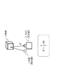
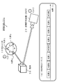
- FIG. 7 is a diagram illustrating an outline of a process executed by a distance measurement device according to the present disclosure.
- FIG. 9 is a diagram for explaining a phase synchronization process.
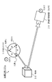
- FIG. 1 is a diagram illustrating a configuration example of a distance measurement system according to the present disclosure.
- FIG. 3 is a diagram illustrating a specific configuration example of a light source unit.
- FIG. 6 is a diagram illustrating an example of drive control of a light source in which each light source is set to be driven in a time-division manner. It is a figure explaining the detailed composition of a distance measuring device (camera).
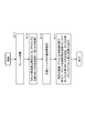
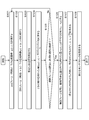
- FIG. 7 is a diagram illustrating a flowchart illustrating an entire sequence of distance measurement using the distance measurement system of the present disclosure.
- FIG. 7 is a diagram illustrating a flowchart illustrating an entire sequence of distance measurement using the distance measurement system of the present disclosure.
- FIG. 9 is a diagram for describing details of a frame synchronization process.
- FIG. 4 is a diagram for describing a process of estimating a clock frequency. It is a figure showing the flow chart explaining the sequence of the frequency synchronization processing in the distance measuring device (camera).
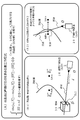
- FIG. 9 is a diagram illustrating a specific example of processing for calculating the position and orientation of a light source unit and calculating a subject distance.
- FIG. 9 is a diagram illustrating a specific example of processing for calculating the position and orientation of a light source unit and calculating a subject distance.
- FIG. 6 is a flowchart illustrating a specific processing sequence of a calculation process of a position and orientation of a light source unit and a calculation of a subject distance. It is a figure explaining the component which performs the calculation processing of the position and orientation of the light source unit and the subject distance calculation in the distance measurement device (camera).
- FIG. 9 is a diagram illustrating a specific example of processing for calculating the position and orientation of a light source unit and calculating a subject distance.
- FIG. 6 is a flowchart illustrating a specific processing sequence of a calculation process of a position and orientation of a light source unit and a calculation of a subject distance. It is a figure explaining the component which performs the calculation processing
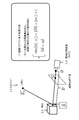
- FIG. 11 is a diagram illustrating a specific processing example in a case where an offset calculation process based on a clock phase difference and a distance (depth) calculation process of an object are performed.
- FIG. 11 is a diagram illustrating a specific processing example in a case where an offset calculation process based on a clock phase difference and a distance (depth) calculation process of an object are performed.
- FIG. 4 is a diagram illustrating a hyperboloid.
- FIG. 7 is a flowchart illustrating a specific processing sequence in a case where an offset calculation process based on a clock phase difference and a distance (depth) calculation process of an object are performed.
- FIG. 4 is a diagram illustrating components that perform an offset calculation process based on a clock phase difference and a distance (depth) calculation process for an object in a distance measurement device (camera).
- FIG. 9 is a diagram illustrating a specific example of a process of calculating a distance (depth) of an object when a light source position and a light source clock offset are known.
- FIG. 3 is a diagram illustrating components that perform processing for calculating a distance (depth) of an object when a light source position and a light source clock offset are known in a distance measurement device (camera). It is a figure explaining the example of composition which does not generate a multiple solution in the solution of the simultaneous equation of a hyperboloid equation and a straight line equation.
- FIG. 14 is a diagram illustrating an example of using the distance measurement system of the present disclosure.
- FIG. 14 is a diagram illustrating an example of using the distance measurement system of the present disclosure.
- FIG. 14 is a diagram illustrating an example of using the distance measurement system of the present disclosure.
- FIG. 14 is a diagram illustrating an example of using the distance measurement system of the present disclosure.
- FIG. 14 is a diagram illustrating an example of using the distance measurement system of the present disclosure.
- FIG. 14 is a diagram illustrating an example of using the distance measurement system of the present disclosure.
- FIG. 14 is a diagram illustrating an example of using the distance measurement system of the present disclosure.
- FIG. 2 is a diagram illustrating a hardware configuration example of a distance measurement device according to the present disclosure.
- the ToF (Time of Flight) method is one of the methods for measuring the distance to an object and the three-dimensional shape of the object.
- the ToF method is a method of irradiating an object with light and analyzing the reflected light to measure the distance (depth) to the object and the shape of the object.
- the outline of the distance (depth) measurement processing by the ToF method will be described with reference to FIG.
- the measurement processing of the three-dimensional shape is not particularly mentioned, but the three-dimensional shape of the object can be measured by measuring the distance of the object surface over the entire object surface.
- FIG. 1 shows a light source (light emitting unit) 1, a camera (light receiving unit) 2, and an object 3.
- Light output from a light source (light emitting unit) 1 is reflected by an object 3 and enters a camera (light receiving unit) 2.
- the distance (depth) d from the camera 2 to the object 3 can be measured by measuring the time ⁇ t from when the output light from the light source 1 is reflected by the object 3 and enters the camera 2. .
- the light source 1 and the camera 2 are shown at a position slightly apart for simplicity.
- the light emission timing of the light source 1 and the imaging timing of the camera 2 are represented by one clock.
- the light source 1 and the camera 2 are configured at substantially the same position such as the same device. Therefore, the time ⁇ t from the time when the output light from the light source 1 is reflected on the object 3 and enters the camera 2 is the time for the light to travel twice the distance (depth) d from the camera 2 to the object 3. . This is the reason why (1/2) is multiplied in the equation for calculating the distance d in (Equation 1).
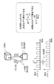
- the time ⁇ t is a very short time, and it is difficult to accurately measure the time ⁇ t. Therefore, in practice, pulse light is emitted from the light source 1 and the time difference between the pulse lights received by the camera 2 is converted into a phase difference to determine the distance. This processing will be described with reference to FIG.
- FIG. 2 also shows a light source (light emitting unit) 1, a camera (light receiving unit) 2, and an object 3, similarly to FIG.
- the pulse light is emitted from the light source 1, and the camera 2 receives the pulse light that has returned after being reflected by the object 3.
- the time difference between the output pulse light of the light source 1 and the input pulse light of the camera 2 is converted into a phase difference and observed.
- the light source 1 blinks at a known frequency fHz at high speed. That is, one cycle of the light emission pattern of the light source 1 is 1 / f second.
- the camera 2 measures the phase of the light blinking pattern for each pixel. A specific example of the phase measurement configuration in pixel units will be described later with reference to FIG.
- FIG. 3 a description will be given of a configuration of calculating the phase of the pulse light in pixel units in the camera 2.
- FIG. The camera 2 described with reference to FIGS. 1 and 2 is a ToF camera different from a normal camera, and each pixel repeatedly turns ON / OFF at high speed, and accumulates electrification only during the ON period.
- the ON / OFF execution timing is sequentially switched to analyze the accumulated charge at each timing.
- the ON / OFF execution timing switching patterns are, for example, the following four types shown in the left diagram of FIG. (C1) phase 0 degree, (C2) 90 degrees phase, (C3) 180 degrees phase (c4) 270 degrees phase
- the phase 0 degree is a setting in which the ON timing (light receiving timing) is set to the phase of the pulse light output from the light source 1, that is, the same phase as the light emission pattern (a) shown in the left diagram of FIG. (C2)
- the phase of 90 degrees is set such that the ON timing (light reception timing) is delayed by 90 degrees from the pulse light ((a) light emission pattern) output from the light source 1.
- the phase of 180 degrees is a setting in which the ON timing (light reception timing) is delayed by 180 degrees from the pulse light ((a) light emission pattern) output from the light source 1.
- the phase 270 degrees is a setting in which the ON timing (light reception timing) is delayed by 270 degrees from the pulse light ((a) light emission pattern) output from the light source 1.
- these four types of switching are sequentially performed, and the light receiving amount with the light receiving timing changed is obtained. That is, four types of light receiving amounts with different accumulation phases and electric charges corresponding to the light receiving amounts are obtained. For example, the charges accumulated when the phase difference of the light receiving pixel with respect to the light emitting pattern is 0 , 90 , 180 , and 270 degrees are Q 0 , Q 90 , Q 180 , and Q 270 , respectively.
- phase difference ⁇ required to calculate the distance d to the object by applying the above-described (Equation 3) is the phase of the output pulse light of the light source 1 and the phase of the received pulse light of the camera 2 Is the difference.
- This phase difference ⁇ can be calculated based on the following (Equation 4).
- ⁇ Arctan ((Q 90 ⁇ Q 270 ) / (Q 180 ⁇ Q 0 )) (Equation 4)
- each phase setting of an image frame captured by a ToF camera that is, a phase shift amount of 0 °, 90 °, 180 °, and 270 ° with a light emission pattern (pulse) is set.
- the captured images and the accumulated charges of each captured image are called components.
- FIG. 4 is a diagram showing image data captured by a camera (ToF camera) according to a time axis shown from left to right. Photographed images with phase shift amounts of 0, 90, 180, and 270 degrees from the light emission pattern (pulse) are sequentially and repeatedly photographed.
- One set of combinations of components for each of the phase settings of 0, 90, 180, and 270 degrees is called a frame. That is, one frame includes the accumulated charge information Q 0 , Q 90 , Q 180 , and Q 270 of the captured image with the phase shift amounts of 0 °, 90 °, 180 °, and 270 ° from the light emission pattern (pulse). have.
- the time between components is set shorter than the time between frames.
- the control of the ON / OFF timing of the light emission pulse of the light source and the ON / OFF timing of the pixel executed in the camera may be executed based on one clock, that is, may be executed in synchronization. .
- the light source 1 and the camera 2 are configured in, for example, one device and controlled by a clock signal from one clock, the light emission pulse of the light source and the charge accumulation timing of the camera 2 are synchronized.
- This allows the performed processing. That is, it is possible to acquire a component composed of a captured image with each phase setting of 0, 90, 180, and 270 degrees in phase shift amount with the light emission pattern (pulse).
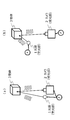
- the light path from the light source 1 to the camera 2 is twice as long as the distance d to the object 3, that is, 2 d. There is a problem that the distance measurement accuracy decreases.
- FIG. 5B As a configuration for solving the problem that the received light intensity of the camera 2 is reduced and the distance measurement accuracy is reduced, a configuration shown in FIG. In the configuration shown in FIG. 5B, the light source 1 is placed near the object 3. With such a setting, it is possible to shorten the path from the output light of the light source 1 to the object 3 and to the reception of the light by the camera 2. Accuracy can be improved.
- each device must be controlled by an individual clock signal.
- the light source 1 and the camera 2 are controlled by different clock signals, it becomes difficult to completely match the control timings of the light source 1 and the camera 2, that is, to synchronize them. If synchronization is not achieved, it is not possible to accurately acquire a component composed of a captured image with a phase shift amount of 0 °, 90 °, 180 °, and 270 ° from the light emission pattern (pulse).
- the frame synchronization process is a synchronization process for acquiring the light emission timing on the light source 1 side for each of the frames and components acquired on the camera 2 side.
- the frequency synchronization process is a process of confirming a frequency deviation between the clocks of the light source 1 and the camera 2 and adjusting so as to eliminate the frequency deviation. For example, even if the clocks of the light source 1 and the camera 2 are set to 100 MHz, the clock of the light source 1 often reaches 100.0001 MHz due to individual differences between the clocks, and this difference is accurately grasped. It is necessary.
- the phase synchronization process is a process of checking a phase shift between the clocks of the light source 1 and the camera 2 and adjusting the phase so as to eliminate the phase shift.
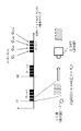
- the waveform (Light (t)) of the light source 1 is a sine wave described below.
- Light (t) cos (f L t + ⁇ L )
- the emission start time t 1 of the light source 1 for emitting light in accordance with the sinusoidal wave as shown in FIG. 6, f L the process of estimating the theta L is required.
- FIG. 7 illustrates an overall configuration example of an embodiment of the distance measurement system according to the present disclosure.
- the distance measurement system according to the present disclosure is a system in which the light source and the camera can be controlled by individual clocks, similarly to the configuration described above with reference to FIG. In other words, the system enables the clock for controlling the light emission timing of the light source and the clock for controlling the imaging timing of the camera to be separate clocks.
- the light source can be placed at an arbitrary position away from the camera. This makes it possible to place the light source near the object whose distance is to be measured.
- the camera that reflects the light emitted from the light source to the distance measurement target object and captures the reflected light can capture the reflected light without decreasing the light intensity, and realizes highly accurate distance measurement. be able to.
- the system according to the present disclosure has a configuration in which the optical path from the time when the output light from the light source is reflected on the object to be incident on the camera can be set short.
- the clock (CLK1) that determines the control timing of the light source of the distance measurement system according to the present disclosure and the clock (CLK2) that determines the control timing of the camera are different clocks, and a process that considers this clock deviation may be performed. Required. This processing will be described later in detail.
- the distance measurement system according to the present disclosure illustrated in FIG. 7 includes the light source unit 10 and the distance measurement device (camera) 20.
- the distance measuring device (camera) 20 measures the distance between the object 30 and the distance measuring device (camera) 20. Further, with the distance measurement, it is also possible to measure the surface shape of the object 30, that is, the three-dimensional shape of the object 30.
- the light source unit 10 has a plurality of light sources a, b, and c. These three light sources are arranged at equal intervals (W).
- the light sources a to c output individual pulse lights.
- the output timing of the pulse light, that is, the phase control is performed by a clock signal of one clock (CLK1).
- the light source unit 10 has three light sources whose relative positions are fixed.
- the number of light sources is not limited to three, but may be a configuration having three or more light sources, such as four, five, or only two depending on the processing.
- the configuration and processing using the light source unit 10 having three light sources, and the configuration and processing using the light source unit 10 having two light sources will be described.
- the output pulse lights of the three light sources a to c of the light source unit 10 are reflected on the surface of the object 30 and enter the distance measuring device (camera) 20.
- the distance measuring device (camera) 20 has a ToF sensor similar to the ToF camera described above with reference to FIGS. 2 to 4, and has an image set with different light receiving timings, that is, a frame including a plurality of components. To get.
- the control timing of the distance measuring device (camera) 20 is executed based on a clock signal output from a clock (CLK2) unique to the camera.
- the light source unit 10 includes a plurality of light sources and a clock.
- the light source unit 10 includes a light source unit clock (CLK1) 101, a light source control unit 102, delay control units 103 to 105 corresponding to each light source, and a plurality of light sources a106, b107, and c108.
- CLK1 light source unit clock
- a light source control unit 102 delay control units 103 to 105 corresponding to each light source
- a plurality of light sources a106, b107, and c108 Have. Since the plurality of light sources a to c are controlled by one light source unit clock 101, the frequency of the emitted light (pulse light) is the same (or a known multiple).
- the frequency setting of the output pulse light from the light sources a to c can be set as follows.
- All pulsed light from the light sources a to c are set to 10 MHz.
- the pulse light of the light sources a to c is set to a prescribed multiple such as 10 MHz, 20 MHz, 30 MHz, etc. For example, the above settings can be made.
- phase of the pulsed light from each of the light sources a to c also depends on the length of the wiring from the clock 101 to the light sources a to c. .
- the phases of the plurality of light sources a to c are the same and there is no deviation. Even if the phases of the individual light sources are shifted, if the shift amount is known, the light sources can be used after being corrected at a later stage.
- each of the light sources a to c is fixed as shown in FIG.
- the light sources a to c are fixed to the housing of the light source unit 10 and are fixed such that the distance between the light sources is W.
- the configuration in which a plurality of light sources are physically fixed is the light source unit 10.
- a light source coordinate system is defined with a certain point in the light source unit 10 as a reference. Since the components inside the light source unit are fixed, the position of each light source is known in the light source coordinate system.
- Light emission timings of the light sources a to c are adjusted by the light source control unit 102 and the delay adjustment units 103 to 105.
- the light source control unit 102 and the delay adjustment units 103 to 105 control the light emission timing of the light sources a to c with a clock supplied from the light source unit clock 101.
- the delay adjusters 103 to 105 control the light emission timing delay amounts of the light sources a to c and 105 to 108, respectively.
- each light source is driven in a time-division manner.
- the light emission frequency of each light source is set differently.
- the light emission frequency of each light source is set differently, such as 1 time, 2 times, or 3 times the clock frequency.
- C Change the wavelength used by each light source. For example, light having different wavelengths such as 850 nm, 905 nm, and 940 nm is used.
- FIG. 9 shows an example of drive control of the light source in which “(a) each light source is driven in a time-division manner” is set.
- FIG. 9 shows an example of clocks and signals supplied from the light source unit clock 101 and light emission pulses of the light sources a to c.
- the example shown in FIG. 9 is a setting in which the light sources a to c sequentially emit light at the same frequency and phase with respect to the reference clock (light source unit clock) while changing the timing. Note that a light-off period is provided to make it possible to identify which light source is currently emitting light.
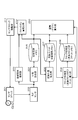
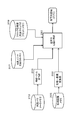
- the distance measuring device (camera) 20 includes a sensor clock 201, a ToF sensor 202, a moving subject detecting unit 203, a phase calculating unit 204, a phase image memory 205, a light source position estimating unit 206, a light source unit position and orientation.
- the memory 207 includes a memory 207, a clock phase difference (light source clock offset) calculating unit 208, a clock phase difference (light source clock offset) memory 209, a clock shift amount estimating unit 210, a sensor clock adjusting unit 211, and a distance (depth) calculating unit 220.
- the ToF sensor 202 is configured by an image sensor similar to the ToF camera described above with reference to FIGS. That is, an image in which different light receiving timings are set, that is, a frame including a plurality of components is obtained.
- the clock signal output from the sensor clock 201 determines the light receiving timing of the ToF sensor 202.
- the moving subject detection unit 203 detects a moving subject from an image captured by the ToF sensor 202.
- This moving subject detection processing is used in the above-described frequency synchronization processing, that is, the synchronization processing for correcting a clock deviation between the light source and the ToF sensor. Details of this processing will be described later.
- the phase calculation unit 204 calculates the phase difference ⁇ between the light emission pulse and the light reception pulse described above with reference to FIGS.
- the light emission pulse is a light emission pulse of each of the light sources a to c of the light source unit 10
- the light reception pulse is a light reception pulse corresponding to the output light of the light sources a to c received by the ToF sensor 202.
- the phase image memory 205 stores a frame image composed of components (phase images) captured by the ToF sensor 202 and phase difference data calculated by the phase calculation unit 204.
- the light source position estimating unit 206 performs a process of estimating the position and orientation of the light source unit 10, specifically, for example, a three-dimensional position estimating process of the light sources a to c. This specific processing example will be described later.
- the light source unit position and orientation memory 207 stores the position and orientation information of the light source unit 10 estimated by the light source position estimating unit 206 (three-dimensional position information of the light sources a to c).
- a clock phase difference (light source clock offset) calculation unit 208 performs a process of calculating a shift between the sensor clock 201 and the light source unit clock 101, that is, a clock phase difference, and stores the calculated clock phase difference in a clock phase difference (light source clock offset) memory 209. To be stored. Details of this processing will be described later.
- the clock shift amount estimating unit 210 estimates the shift amount of the frequency between the sensor clock 201 and the light source unit clock 101.
- the sensor clock adjustment unit 211 adjusts the frequency of the sensor clock 201 based on the amount of deviation between the sensor clock 201 and the light source unit clock 101 estimated by the clock deviation amount estimation unit 210. That is, frequency adjustment is performed to eliminate or reduce the difference between the clock frequency of the sensor clock 201 and the clock frequency of the light source unit clock 101. Details of this processing will also be described later.
- the above-mentioned clock phase difference (light source clock offset) calculation unit 208 calculates this clock phase difference.
- the distance (depth) calculation unit 220 calculates the distance (depth) of the object 30 to be measured.
- the calculated distance is a distance from the distance measuring device (camera) 20 to the surface of the object 30.
- phase image memory 205 For this distance calculation, data stored in the phase image memory 205, the light source unit position and orientation memory 207, and the clock phase difference (light source clock offset) memory 209 are used. That is, (A) A frame image composed of components (phase images) captured by the ToF sensor 202 and stored in the phase image memory 205, and phase difference data calculated by the phase difference calculation unit 204. (B) Position and orientation information of the light source unit 10 (three-dimensional position information of the light sources a to c) estimated by the light source position estimation unit 206 stored in the light source unit position and orientation memory 207.
- C Clock phase difference (light source clock offset)
- the distance calculation using these is performed. Details of this processing will be described later.
- Step S11 a frame synchronization process is executed in step S11.
- the frame synchronization process is a synchronization process for acquiring the light emission timing on the light source side for each of the frames and components acquired on the camera side as described above with reference to FIG.
- step S11 the light emission timing on the light source unit 10 side for each frame or component obtained on the distance measurement device (camera) 20 side is obtained. The specific processing will be described later.
- Step S12 a frequency synchronization process is performed.
- This process is a process of confirming a difference between the frequency of the sensor clock used on the distance measuring device (camera) 20 side and the frequency of the light source unit clock used on the side of the light source unit 10 and adjusting so as to eliminate the frequency difference. is there.
- This process requires a process in which the distance measuring device (camera) 20 estimates the frequency of the clock used in the light source unit 10.
- Step S13 the position and orientation of the light source unit 10 are estimated.
- the light source unit 10 includes a plurality of light sources a to c.
- step S13 a process of estimating the positions of these light sources a to c is performed.
- Step S14 a distance (depth) measurement process of the object 30 is executed. That is, the distance from the distance measuring device (camera) 20 to the object 30 is measured.
- a calculation process of an offset C corresponding to a distance measurement error generated based on a clock phase difference, that is, a phase difference between the sensor clock and the light source clock is executed. The detailed processing of S11 to S14 in these steps will be described later.
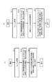
- FIG. 11 is a basic flow of a processing sequence executed by the distance measurement device (camera) 20 of the present disclosure, but the distance measurement device (camera) 20 of the present disclosure is illustrated in FIG.
- steps S11 and S12 are the same processing as steps S11 and S12 of the flow shown in FIG.
- the following processing is performed in step S21 after the clock frequency synchronization processing in step S12.
- Step S21 the process of estimating the position and orientation of the light source unit 10 and the calculation of the distance to the object, that is, the distance from the distance measurement device (camera) 20 to the object 30 are executed together.
- the process of step S21 corresponds to a process of executing the process of step S13 and the process of step S14 of the flow shown in FIG.
- steps S11 to S13 are the same processing as steps S11 to S13 in the flow shown in FIG. In the flow illustrated in FIG. 12B, the following processing is performed in step S31 after the position and orientation estimation processing of the light source unit 10 in step S13.
- step S31 an object distance (depth) measurement process is performed by applying the clock phase difference, that is, the offset C based on the phase difference between the sensor clock and the light source clock, that is, the value of the distance measurement error based on the clock phase difference.
- the process according to the flow shown in FIG. 12B is a flow executed when the offset C based on the clock phase difference has already been calculated and stored in the memory.
- the distance measuring device (camera) 20 uses the sequence shown in FIGS. 12A and 12B, for example, in addition to the processing according to the flow shown in FIG. Depth) can also be calculated. Details of these processes will be described below.
- the frame synchronization process is a process of acquiring the light emission timing on the light source unit 10 side for each of the frames and components acquired on the distance measuring device (camera) 20 side. This specific processing example will be described with reference to FIG.
- the three light sources a to c of the light source unit 10 sequentially emit light at the same frequency and phase with respect to the light source unit clock, which is the reference clock, while changing the timing. Further, a light-off period is provided to make it possible to identify which light source is currently emitting light. After the light-off period, light is emitted in the order of the light sources a ⁇ b ⁇ c, and after that, after a predetermined light-off period, light emission in the order of the light sources a ⁇ b ⁇ c is repeated.
- the distance measuring device (camera) 20 needs to identify when and which light source emitted light.
- the light source unit 10 sequentially turns on the light sources at regular intervals with a light-off period, as shown in the lower part of FIG.
- the distance measuring device (camera) 20 has confirmed in advance the lighting time, lighting order, and length of the light-off period of each light source.
- the distance measuring device (camera) 20 first detects an initial light-off period after starting photographing. Once the light-off period can be detected, thereafter, it is determined which light source is currently turned on by considering the periodicity (in the order of light sources a ⁇ b ⁇ c).
- the frame synchronization processing in step S11 of the flow shown in FIG. 11 is this processing, and it is determined which broad pulse output light of the light source unit 10 is the pulse light received by the distance measuring device (camera) 20. Processing.
- the process in step S12 is a frequency synchronization process.
- This process is a process of confirming a difference between the frequency of the sensor clock used on the distance measuring device (camera) 20 side and the frequency of the light source unit clock used on the side of the light source unit 10 and adjusting so as to eliminate the frequency difference. is there.
- This process requires a process in which the distance measuring device (camera) 20 estimates the frequency of the clock used in the light source unit 10.
- This processing is to synchronize the sensor clock (CLK2) on the distance measuring device (camera) 20 side shown in FIG. 14 with the light source unit clock (CLK1) on the light source unit 10 side. Is to adjust the side sensor clock (CLK2).
- the light source unit 10 has three light sources a to c, all of which use the same light source unit clock (CLK1), and therefore may be adjusted using the output light of any one of the light sources. For example, a processing example using the output light of the light source a will be described.
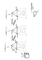
- the light receiving signal is a frame including the components shown in (a1) on the right side of FIG. That is, it is a frame constituted by components in which the accumulation phase is sequentially changed (0, 90, 180, 270 degrees) as described above with reference to FIGS.
- a plurality of frames composed of these four components are acquired in time series.
- the distance measurement device (camera) 20, the light source unit 10, and the object 30 are all at fixed positions where they do not move.
- the phase difference ⁇ between the output pulse of the light source a of the light source unit 10 and the light receiving pulse of the distance measuring device (camera) 20 is determined by the light source unit 10 to the object 10 to the distance measuring device (camera) 20 and the route. The phase difference depends on the time of light.
- the distance measuring device (camera) 20, the light source unit 10, and the object 30 are all in fixed positions where they do not move, and the sensor clock (CLK2) on the distance measuring device (camera) 20 side and the light source on the light source unit 10 side If the frequency matches the unit clock (CLK1), as shown in (a21) on the right side of FIG. 14, the output pulse of the light source a of the light source unit 10 and the output pulse of the light source unit 10 in any frame acquired in time series.
- the phase difference ⁇ from the light receiving pulse of the distance measuring device (camera) 20 should be unchanged.
- the frequency of the sensor clock (CLK2) on the distance measuring device (camera) 20 side does not match the frequency of the light source unit clock (CLK1) on the light source unit 10, that is, if there is a deviation, (a22) on the right side of FIG.
- the phase difference ⁇ between the output pulse of the light source a of the light source unit 10 and the light receiving pulse of the distance measuring device (camera) 20 changes in accordance with the progress of the frames acquired in time series.
- the distance measuring device (camera) 20 uses the sensor clock (CLK2) on the distance measuring device (camera) 20 side and the light source unit clock on the light source unit 10 side. It is determined that there is a deviation in the frequency from (CLK1), and a sensor clock adjustment process is performed to eliminate this deviation.
- the detailed sequence of the sensor clock adjustment process is as follows. First, the following two frequencies of the clock with a deviation f L, and f S. f L : light source unit clock frequency f S : sensor clock frequency
- the clock shift amount of the two clocks for T seconds is (F L ⁇ f S ) T Becomes
- the phase shift amount of the clock for T seconds between the two clocks is 2 ⁇ (f L ⁇ f S ) T Becomes
- the phase shift amount ( ⁇ ) per unit time (1 second) corresponds to the inclination of the graphs shown in (a21) and (a22) of FIG.
- the data shown in (a21) and (a22) of FIG. 14 are data obtained as observation values of the distance measuring device (camera) 20. That is, the phase shift amount ( ⁇ ) per unit time (1 second) can be obtained based on the observation data.
- the distance measuring device (camera) 20 performs processing (frequency synchronization processing) for eliminating or reducing the difference between the frequency of the sensor clock and the frequency of the light source unit clock based on the frequency difference between the two clocks calculated according to the above equation.
- processing frequency synchronization processing
- Frequency f 'S of the new sensor clock after adjustment is a frequency obtained by the following equation.
- f ′ S f S + ( ⁇ / 2 ⁇ )
- step S12 of the flow in FIG. 11 that is, the frequency shift between the sensor clock used on the distance measuring device (camera) 20 side and the light source unit clock used on the light source unit 10 side is confirmed.
- an adjustment process for eliminating the frequency deviation is performed.
- FIG. 15 is a flowchart illustrating a processing sequence of the frequency synchronization processing.
- FIG. 16 is a configuration diagram similar to the configuration of the distance measurement device (camera) 20 described above with reference to FIG. 10, and components used in the frequency synchronization processing are indicated by thick frames.
- step S101 a phase image ⁇ (t, x) is measured based on one frame acquired at time t.
- This process is executed by the phase difference calculation unit 204 shown in FIG. 16 based on one frame input from the ToF sensor 202.
- This process corresponds to the process of acquiring the phase difference ⁇ at time t of frame 1 in FIG. 14 (a21) or (a22) described above with reference to FIG.
- x indicates the pixel position of the acquired image.
- step S102 a phase image ⁇ (t + ⁇ t, x) is measured based on one frame acquired at time t + ⁇ t. This process is also executed by the phase difference calculation unit 204 shown in FIG. 16 based on one frame input from the ToF sensor 202.
- Step S103 Next, in step S103, a moving subject position included in the obtained frame is detected.
- This process is a process executed by the moving subject detection unit 203 shown in FIG.
- step S103 is performed to remove such a photographed pixel of the moving subject from the processing target.
- Step S104 Next, in step S104, using the phase image ⁇ (t, x) and the phase image ⁇ (t + ⁇ t, x) acquired in steps S101 to S102, the phase shift amount ⁇ (t, x) is calculated based on the following equation.
- ⁇ (t, x) ( ⁇ (t + ⁇ t, x) ⁇ (t, x)) / ⁇ t
- x indicates the pixel position of the acquired image, and the phase shift amount ⁇ (t, x) per unit time (1 second) is calculated for each pixel position. This process is executed by the phase difference calculation unit 204 shown in FIG. Note that x indicates the pixel position of the acquired image.
- step S105 it is determined whether or not the processing of steps S101 to S104 has been completed a specified number of times as repetition processing of a plurality of frames. If the specified number of times has not been reached, the processing from step S101 is repeated. If the specified number has been reached, the process proceeds to step S106.
- Step S106 Next, in step S106, pixel corresponding data of the moving subject position is removed from the phase shift amount ⁇ (t, x) of each pixel calculated in step S104, and the phase shift amount ⁇ (t, The average value of x) is calculated, and this is defined as the phase shift amount ( ⁇ ) per unit time (1 second).
- This process is executed by the clock shift amount estimating unit 210 shown in FIG.
- moving object pixel correspondence data is not included is that accurate frequency synchronization processing cannot be performed using the light reflected by the moving object when the object is moving as described above.
- step S107 the current sensor clock frequency f S, the new adjustment sensor clock frequency f 'S which substantially coincide with the frequency of the light source unit clock is calculated according to the following equation.
- f ′ S f S + ( ⁇ / 2 ⁇ ) This process is executed by the clock shift amount estimating unit 210 shown in FIG.
- step S108 the adjustment sensor clock frequency f 'S calculated in step S107, it sets the frequency of the sensor clock.
- This process is a process executed by the sensor clock adjustment unit 211 shown in FIG.
- the frequency deviation between the sensor clock (CLK2) on the distance measuring device (camera) 20 side and the light source unit clock (CLK1) on the light source unit 10 side is almost eliminated.
- the clock adjusting unit 211 is provided on the distance measuring device (camera) 20 side, and the light source unit clock (CLK1) on the light source unit 10 side and the sensor clock (CLK2) on the distance measuring device (camera) 20 side.
- a clock adjustment unit is provided on the light source unit 10 side, and adjustment is performed on the light source unit 10 side to eliminate or reduce the frequency difference between the two clocks. It may be configured.
- step S13 details of the position and orientation estimation processing of the light source unit in step S13 described with reference to the flowchart shown in FIG. 11 will be described. Further, in this item, a specific example of the processing in step S21 described with reference to the flowchart illustrated in FIG. 12A, that is, the processing in the case where the estimation of the position and orientation of the light source unit and the calculation of the distance are performed together is also described. Will be explained.
- step S13 of the flow shown in FIG. 11 is a process of estimating the position and orientation of the light source unit 10.
- the light source unit 10 includes a plurality of light sources a to c.
- step S13 a process of estimating the three-dimensional position of each of the light sources a to c is performed. Do.
- step S21 corresponds to a process of executing the process of step S13 and the process of step S14 of the flow shown in FIG.
- FIG. 17 and FIG. 18 are diagrams illustrating the procedure of the processing for estimating the position and orientation of the light source unit.
- the position and orientation estimation processing of the light source unit is executed under the following premise.
- the light source coordinate system which is the coordinate system of the light source unit, is defined. If it is not defined, define it. However, the relative position between the light source coordinate system and the camera coordinate system is unknown.
- B The relative position of each light source in the light source unit is known. That is, each light source position is known in the light source coordinate system.
- C It is not known where the entire light source unit is located.
- D It is assumed that the clock frequencies of the light source clock and the sensor clock are substantially the same (adjustment is completed) or the deviation is known. However, the phase shift remains.
- the position and orientation estimation processing of the light source unit 10 specifically, the three-dimensional position estimation processing of each of a plurality of light sources provided in the light source unit 10 is performed.
- the light source position estimating unit 206 of the distance measuring device (camera) 20 shown in FIG. The detailed configuration of the light source position estimating unit 206 will be described later with reference to FIG.
- the light source position estimating unit 206 executes the first half of the procedure (step S1) of the light source position estimating process procedure shown in FIG. That is, in (Step S1), the distance (from each light source a to c to the distance measurement device (camera) 20) using a frame acquired based on the light receiving pulse of the pulse emitted by each of the light sources a to c of the light source unit 10. Is calculated).
- vector notation parameters (parameters indicated by ⁇ above each parameter) in the above (Equation 11) indicate a vector from a certain coordinate system, for example, the origin of a light source coordinate system.
- Each parameter in the above (Equation 11) has the following meaning.
- C is an offset term corresponding to a measured distance error caused by a phase shift between clocks of the light source unit 10 and the distance measuring device (camera) 20;
- Obs (u D , E 1 ) is the distance observed at pixel position u D when light source a located at position E 1 emits light
- Obs (u D , E 2 ) is the distance observed at pixel position u D when light source b located at position E 2 emits light
- Obs (u D , E 3 ) is the distance observed at pixel position u D when light source c located at position E 3 emits light
- u D (u D , v D ) is the pixel position where the point D is projected
- O is the origin of the camera coordinate system, which is the coordinate system of the distance measuring device (camera) 20.
- D is a reflection position of the light from the light source on the object 30.
- DEn is the magnitude (distance) of the vector connecting each light source at the position En and the reflection position on the object 30 It is.
- vector notation is omitted. In the following description, vector notation is omitted in the description of the specification.
- the light source position estimating unit 206 calculates (step S1) three distance calculation expressions from the three light sources a to c mounted on the light source unit 10 to the distance measuring device (camera) 20 as: (A) distance data
- the light source position estimating unit 206 executes the latter half of the procedure of the light source position estimating process shown in FIG. 18A (steps S2 to S3). That is, in (Step S2), the three distances calculated in Step S1 are: Obs (u D , E 1 ), Obs (u D , E 2 ), Obs (u D , E 3 ), and the distances of these distances.
- a simultaneous equation including a difference calculation formula is generated. This is a simultaneous equation shown in the following (Equation 12).
- step S3 and by solving the above simultaneous equations, obtains a plurality of subject position L Dk at the light source coordinate system, the corresponding pixel position u k. Since each light source position viewed from the camera coordinates is unknown, this equation cannot be directly solved in the camera coordinate system. However, since each light source position in the light source coordinate system is known, it can be solved in the light source coordinate system.
- the simultaneous equation shown in the equation (12) by solving with a light source coordinate system, and a plurality of object position L Dk at the light source coordinate system can be obtained the corresponding pixel position u k.
- the plurality of subject positions L Dk include, for example, the positions E 1 , E 2 , and E 3 of the light sources a to c of the light source unit 10 and the surface position of the object 30.
- the relative position and orientation between the coordinate system and the camera coordinate system can be obtained. That is, by solving the so-called PnP (Perspective-n-Point Problem) problem, the relative relationship between the light source coordinate system and the camera coordinate system can be derived, and the subject position in the light source coordinate system can be converted to the camera coordinate system.
- PnP Perspective-n-Point Problem
- the object position L Dk in the camera coordinate system and the corresponding pixel position u k can be obtained, and the positions E 1 , E 2 of the light sources a to c are determined from the imaged pixel positions of the light sources a to c. , it is possible to determine E 3 and the surface position of the object 30 in the camera coordinate system.
- the distance to the object 30, that is, the distance between the distance measuring device (camera) 20 and the object can be calculated.
- FIG. 20 is a diagram illustrating a detailed configuration of the light source position estimating unit 206 of the distance measuring device (camera) 20 described above with reference to FIG.
- Step S201 the distance (from the light sources a to c to the distance measurement device ( Camera) 20 is calculated.
- the light source position estimating unit 206 calculates three distances from the three light sources a to c attached to the light source unit 10 to the distance measuring device (camera) 20 as: (A) distance data
- FIG. 20 is a diagram illustrating a detailed configuration of the light source position estimating unit 206 of the distance measuring device (camera) 20.
- the phase image memories 1 to 3 and 205 correspond to the phase image memory 205 shown in FIG.
- the phase images corresponding to the light sources a to c are individually shown as memories storing the phase images.
- the processing in step S201 is executed by the phase-distance conversion unit 251 shown in FIG.
- Step S202 is a step of determining whether or not acquisition of distance information has been completed for all light sources. If the acquisition of the distance information has not been completed for all the light sources, the process returns to step S201, and the distance information acquiring process for the unprocessed light sources is executed. When the distance information acquisition for all the light sources is completed, the process proceeds to step S203.
- step S203 processing is performed to determine the positions of the plurality of points of interest (subjects) in the light source coordinate system and the coordinates of the points on the image.
- This process is a process corresponding to the process of (steps S2 to S3) in FIG. 18 described above. That is, first, the distances corresponding to the three light sources calculated in (Step S201): Obs (u D , E 1 ), Obs (u D , E 2 ), Obs (u D , E 3 ), and each of these distances To generate a simultaneous equation consisting of a formula for calculating the difference between. This is a simultaneous equation shown in the following (Equation 12) described above.
- This difference calculation process is executed by the difference calculation unit 252 shown in FIG.
- the difference data calculated by the difference calculation unit 252 is output to the subject position calculation unit 253, and the subject position calculation unit 253 solves the above simultaneous equations to obtain a plurality of subject positions L Dk in the light source coordinate system and a corresponding pixel. to calculate the position u k.
- the simultaneous equation shown in the equation (12), by solving with a light source coordinate system, and a plurality of object position L Dk at the light source coordinate system can be obtained the corresponding pixel position u k.
- the plurality of subject positions L Dk include, for example, the positions E 1 , E 2 , and E 3 of the light sources a to c of the light source unit 10 and the surface position of the object 30.
- Steps S204 to S205 As described above with reference to FIG. 18, generally, if the correspondence between a plurality of points in a certain coordinate system and the pixel position at which the point is projected by the camera is known, the coordinate system and the camera coordinates The relative position and orientation of the system can be determined.
- a relative relationship between the light source coordinate system and the camera coordinate system is derived by solving a PnP (Perspective-n-Point Problem) problem.
- This process is executed by the light source-camera positional relationship estimating unit 254 shown in FIG.
- the light source-camera positional relationship estimating unit 254 obtains a light source coordinate system light source position stored in the light source coordinate system light source position memory 254 and solves a PnP (Perspective-n-Point Problem) problem to obtain a light source coordinate system.
- the relative relationship with the camera coordinate system is derived, and the result is stored in the camera-light source coordinate system relative position DB 256. This information is output to the coordinate conversion unit 257.
- step S205 the object position in the light source coordinate system is converted to the camera coordinate system.
- This processing is executed in the coordinate conversion unit 257.
- the object position L Dk and the corresponding pixel position u k in the camera coordinate system can be obtained, and the positions E 1 , E of the light sources a to c are determined from the pixel positions at which the light sources a to c are photographed.
- the distance to the object 30, that is, the distance between the distance measuring device (camera) 20 and the object can be calculated by obtaining 2 , E 3 and the surface position of the object 30 in the camera coordinate system.
- the distance (depth) calculation processing is performed by the distance (depth) calculation unit 220 of the distance measurement device (camera) 20 described with reference to FIG.
- step S14 Specific processing example in the case of performing an offset calculation process based on a clock phase difference and a distance (depth) calculation process of an object
- step S14 a specific example of the process of step S14 described with reference to the flowchart illustrated in FIG. 11, that is, the offset calculation process based on the clock phase difference and the object distance (depth) calculation process will be described.
- step S14 of the flow illustrated in FIG. 11 is a process of measuring the distance (depth) of the object 30, that is, a process of measuring the distance from the distance measuring device (camera) 20 to the object 30. Further, in this process, a calculation process of an offset C corresponding to a distance measurement error generated based on a clock phase difference, that is, a phase difference between the sensor clock and the light source clock is executed.
- This process is a process that can be executed even when the light source unit 10 has a configuration including two light sources. That is, the light source unit 10 may include two or more light sources.
- phase difference calculation process between the clock on the light source unit 10 side and the clock on the distance measurement device (camera) 20 side is executed under the following premise.
- A) Each light source position of the light source unit 10 is known in the camera coordinate system.
- a phase difference calculation process with the clock on the distance measuring device (camera) 20 side is performed, and further, a subject distance of the object 30 or the like is calculated.
- the clock phase difference calculation process is performed by the clock phase difference (light source clock offset) calculation unit 208 of the distance measurement device (camera) 20 shown in FIG. 10, and the distance is calculated by the distance (depth) The calculation unit 220.
- the clock phase difference (light source clock offset) calculation unit 208 calculates a phase difference with the clock of the distance measuring device (camera) 20 or an offset C corresponding to a distance measurement error based on the phase difference.
- the distance (depth) calculation unit 220 calculates the distance to the object 30 by applying the offset C.
- the offset C is an offset C corresponding to an error amount at the time of distance calculation based on the phase difference between the sensor clock 201 and the light source unit clock 101, and is represented by the equation 11 used in (step S1) described above with reference to FIG. Is the same value as the offset C of the above.
- phase difference calculation process with respect to the clock on the distance measuring device (camera) 20 side and the subject distance calculation process of the object 30 or the like can be executed using only light emission pulses from two light sources of the light source unit 10. As described above, this process can be executed even if the light source unit 10 does not have three light sources and has a configuration including only two light sources.
- FIG. 21 shows only two light sources a and b of the light source unit 10.
- Source a, b is a light source a located at position E 1, a light source b located at position E 2.
- the position is assumed to have been acquired in the camera coordinate system having the origin O at the position of the distance measuring device (camera) 20 shown in FIG.
- the right side of FIG. 21 shows an outline of (1) distance (depth) calculation processing executed by the clock phase difference (light source clock offset) calculation unit 208 and the distance (depth) calculation unit 220.
- Step S1 the distance (from each of the light sources a and b, the distance measuring device (camera) 20) is determined using a frame acquired based on the light receiving pulses of the pulses emitted by the two light sources a and b of the light source unit 10. Distance between them).
- vector notation parameters (parameters indicated by ⁇ above each parameter) in the above (Equation 21) indicate a vector from a certain coordinate system, for example, the origin of a camera coordinate system.
- Each parameter in the above (Equation 21) has the following meaning.
- C is an offset term corresponding to a measured distance error caused by a phase shift between clocks of the light source unit 10 and the distance measuring device (camera) 20;
- Obs (u D , E 1 ) is the distance observed at pixel position u D when light source a located at position E 1 emits light
- Obs (u D , E 2 ) is the distance observed at pixel position u D when light source b located at position E 2 emits light
- u D (u D, v D) is a pixel position point D is projected
- O is the origin of the camera coordinate system, which is the coordinate system of the distance measuring device (camera) 20.
- D is a reflection position of the light from the light source on the object 30.
- DEn is the magnitude (distance) of a vector connecting each light source at the position En and the reflection position on the object 30 It is. In the description of the above equations, vector notation is omitted.
- the distance (depth) calculation unit 220 calculates the two distance calculation expressions from the two light sources a and b attached to the light source unit 10 to the distance measurement device (camera) 20 in (Step S1).
- Step S2 the two distances calculated in Step S1: Obs (u D , E 1 ) and Obs (u D , E 2 ), and a formula for calculating the difference between these distances is generated.
- This is a difference calculation formula shown in the following (Formula 22).
- the offset term C included in the distance calculation formula generated in (Step S1) that is, the measurement distance caused by the phase shift of the clock between the light source unit 10 and the distance measurement device (camera) 20
- the offset term C corresponding to the error can be eliminated.
- Step S3 the distance to the object 30, that is, the distance D between the distance measuring device (camera) 20 and the object 30 is calculated.
- the unit vector d in the vector OD direction from the origin O of the distance measuring device (camera) 20 to the surface D of the object 30 is obtained, and the following (Equation 23) is generated.
- Equation 23 is a linear equation connecting the object 30 with the distance measuring device (camera) 20.
- the distance (depth) calculation unit 220 performs (step S3) (D) Generate a linear equation connecting the distance measuring device (camera) 20 and the object 30.
- the position (x, y, z) of the surface D of the object 30 is calculated using this (Equation 23) and the distance difference calculation expression (Equation 22) generated earlier in (Step S2),
- the distance D is calculated based on the position (x, y, z).
- step (S1) the distance (depth) calculation unit 220 calculates two distances from at least two light sources attached to the light source unit 10 to the distance measurement device (camera) 20 as: (A) distance data between the distance measuring device and the object; (B) distance data between the object and each light source of the light source unit; (C) an offset C corresponding to a distance measurement error generated based on a phase difference between the sensor clock and the light source clock; Two distance calculation formulas composed of these data (a) to (c) are generated. Further, in (Step S2), one difference calculation formula for calculating the difference between the distance calculation formulas is generated.
- Step S3 (D) generating a linear equation connecting the distance measuring device and the object;
- the difference between the distance measurement device (camera) 20 and the object 30 is calculated by solving the difference calculation formula and the linear equation as simultaneous equations.
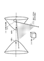
- Difference calculation formula for distance generated in (step S2) (Equation 22) is equivalent to equation showing one side of a two-sheet hyperboloid of light a, a position E 1 and the position E 2 of b and the focal point. In this paper, it is simply described as a hyperboloid for simplicity.
- (Equation 23) generated in (Step S3) corresponds to an equation indicating a straight line connecting the origin O of the distance measuring device (camera) 20 and the surface D of the object 30.
- the position (x, y, z) of the surface D of the object 30 can be calculated.
- the position (x, y, z) is a coordinate indicating a position in the camera coordinate system, and a distance D from the origin O of the camera coordinate system can be calculated based on the position (x, y, z). .
- the distance (depth) calculation unit 220 solves these two equations as a simultaneous equation by solving a difference calculation equation (equation 22) corresponding to the equation of the hyperboloid and an equation (equation 23) corresponding to the linear equation.
- the position (x, y, z) of the surface D of 30 is calculated, and the distance D from the origin O of the camera coordinate system is calculated based on the calculated position (x, y, z).
- FIG. 25 is a diagram showing a detailed configuration of the clock phase difference (light source clock offset) calculation unit 208 and the distance (depth) calculation unit 220 of the distance measurement device (camera) 20 described above with reference to FIG.
- the configuration of the phase-distance conversion unit 271 to the subject position calculation unit 275 other than the clock phase difference (light source clock offset) calculation unit 208 is a component of the distance (depth) calculation unit 220.
- the internal parameter memory 273 is a memory in the distance measurement device (camera) 20 that can be accessed by the distance (depth) calculation unit 220, and stores, for example, camera parameters obtained by a camera calibration process executed in advance. Have been.
- step S301 the distance (the distance from the light source to the distance measurement device (from the light source) to the frame obtained based on the output light from any one of the two light sources a and b of the light source unit 10, that is, the light receiving pulse of the light emitting pulse. Camera) 20 is calculated.
- step S301 The processing in step S301 is executed by the phase-distance conversion unit 271 shown in FIG.
- Step S302 is a step of determining whether or not acquisition of distance information for two light sources has been completed. If the acquisition of the distance information for the two light sources has not been completed, the process returns to step S301, and the distance information acquisition processing for the unprocessed light sources is executed. Upon completion of the distance information acquisition for the two light sources, the process proceeds to step S303.
- the distance calculation formula between the two light sources and the distance measuring device (camera) 20 is calculated by the following (formula 21) described above. This means that the distance information of the expression represented is obtained.
- FIG. 25 is a diagram showing a detailed configuration of the clock phase difference (light source clock offset) calculation unit 208 and the distance (depth) calculation unit 220 of the distance measurement device (camera) 20.
- the phase image memories 1 to 2 and 205 correspond to the phase image memory 205 shown in FIG.
- the phase images corresponding to the light sources a and b are individually shown as memories storing the phase images.
- Step S303 Next, the distances Obs (u D , E 1 ) and Obs (u D , E 2 ) corresponding to the two light sources calculated in (Step S301) are generated, and a difference calculation formula for these distances is generated. This is the difference calculation formula shown in the following (Formula 22) described above.
- This difference calculation process is executed by the difference calculation unit 272 shown in FIG.
- the difference data calculated by the difference calculator 272 is output to the subject position calculator 275.
- Step S304 Next, in step S304, a hyperboloid equation that satisfies the difference calculation formula generated in step S303 is generated using known conditions and known parameters.
- the above-described difference calculation formula (Formula 22) is a formula indicating a part of the hyperboloid. That is, as shown in FIG. 23, if the coordinates of point A are (0, 0, c), point B (0, 0, -c), and
- 2e, the point P will be described first. 23 satisfies (Expression 24), and the figure represented by (Expression 24) is divided into two curved surfaces in the + z direction and the ⁇ z direction in the diagram showing the hyperboloid of FIG. This is because the same (Equation 24) can be obtained even when
- ⁇ 2e.
- step S304 a hyperboloid equation that satisfies the difference calculation formula generated in step S303 is generated using the known conditions and known parameters. This processing is executed by the subject position calculation unit 275 shown in FIG.
- Step S305 a unit vector d in the vector OD direction from the distance measuring device (camera) 20 to the surface D of the object 30 is obtained from the distance measuring device (camera) 20 using known conditions and known parameters. That is, the linear equation shown in (Equation 23) described above is generated. In general, assuming that a pixel position (x, y, z) in a certain space is projected on a camera at a pixel position (u, v), a positional relationship between them is given by the following (Equation 25). Is defined as
- F, cv, and cu are lens parameters (internal parameters) that can be obtained in advance, and are stored in the internal parameter memory 273 shown in FIG.
- the unit vector d corresponding to the line-of-sight vector in the vector OD direction can be obtained.
- a unit vector d in the vector OD direction from the distance measurement device (camera) 20 to the surface D of the object 30 is obtained, and a straight line equation including the unit vector d, that is, A linear equation shown in 23) is generated.
- Step S306 a simultaneous equation composed of the hyperboloid equation generated in steps S303 to S304 and the linear equation generated in step S305 is solved, and the position of the intersection between the hyperboloid and the straight line is calculated. Based on this, the distance D from the distance measuring device (camera) 20 to the surface of the object 30 is calculated.
- This process is a process of calculating the position of the intersection between the hyperboloid and the straight line described above with reference to FIG. That is, this is a process of acquiring the following simultaneous equation composed of these two equations, which is a difference calculation equation (equation 22) corresponding to the equation of the hyperboloid and an equation (equation 23) corresponding to the linear equation.
- the position (x, y, z) of the surface D of the object 30 is calculated by solving the above simultaneous equations.
- the position (x, y, z) is a coordinate indicating a position in the camera coordinate system, and a distance D from the origin O of the camera coordinate system can be calculated based on the position (x, y, z). .
- step S306 is executed by the subject position calculation unit 275 shown in FIG. Thus, the distance to the object 30 can be calculated.
- the clock phase difference (light source clock offset) calculation unit 208 shown in FIG. 25 further performs the distance calculation formula generated in steps S301 to S302, ie, The offset C included in the distance calculation equation of (Equation 21), that is, the value of the distance measurement error generated based on the phase difference between the sensor clock and the light source clock is calculated and stored in the clock phase difference (light source clock offset) memory 209. Store.
- the value of the offset C is a fixed value, it can be used in subsequent distance calculation processing. Since the position and the distance of the object 30 have been calculated by the processing according to the flow shown in FIG. 24, and the light source position has also been obtained, the distance calculation expression of the above (Equation 21) is obtained from these values. Can be used to calculate the value of the offset C. If the value of the offset C can be calculated, the phase difference between the sensor clock and the light source clock can also be calculated based on the value of the offset C. The calculated phase difference can be calculated together with the value of the offset C by the clock phase difference (light source clock offset). ) It may be configured to be stored in the memory 209.
- step S31 of the flow illustrated in FIG. 12B is performed by applying the clock phase difference, that is, the offset C based on the phase difference between the sensor clock and the light source clock, that is, the value of the distance measurement error based on the clock phase difference.
- This is a process of measuring the distance (depth) of the object.
- the processing according to the flow shown in FIG. 12B is a flow executed when the offset C based on the clock phase difference has already been calculated and stored in the memory.
- the clock phase difference (light source clock offset) calculation unit 208 stores the value of the offset C in the clock phase difference (light source clock offset) memory 209. This is a distance calculation process performed after the calculation. Note that, as described above, the offset C corresponds to the value of the distance measurement error generated based on the phase difference between the sensor clock and the light source clock.
- the distance (depth) calculation unit 220 calculates the distance to the object 30 by solving a simultaneous equation of two equations shown on the right side of FIG. That is, it is a simultaneous equation shown in the following (Equation 31).
- Equation 31 The simultaneous equation of the above (Equation 31) is obtained by calculating the distance between the light source a and the distance measuring device (camera) 20 and a straight line including the unit vector d in the vector OD direction from the distance measuring device (camera) 20 to the surface of the object 30. It consists of two equations.
- C is an offset term, which corresponds to the value of the distance measurement error generated based on the phase difference between the sensor clock and the light source clock. . In this processing example, the value of the offset C is known.
- the straight line equation including the unit vector d is the same equation as (Equation 23) described above.
- FIG. 27 is a diagram showing a detailed configuration of the distance (depth) calculation unit 220 that executes this processing. With reference to FIG. 27, a description will be given of a process of generating these simultaneous equations and a process executed by the distance (depth) calculation unit 220 for calculating the distance to the object 30 by solving the simultaneous equations.
- the phase-distance conversion unit 282 uses the frame obtained based on the output light from one light source a of the light source unit 10, that is, the frame obtained based on the light receiving pulse of the light emission pulse, to calculate the distance (from the light source to the distance Distance between them).
- This calculation formula is a distance calculation formula for calculating Obs (u D , E 1 ) in the above (Formula 31).
- the offset C included in the distance calculation formula is a value of a distance measurement error generated based on the phase difference between the sensor clock and the light source clock, and is stored in the clock phase difference (light source clock offset) memory 209 shown in FIG. Is a known value.
- the line-of-sight vector calculation unit 281 and the subject position calculation unit 283 obtain a unit vector d in the vector OD direction from the distance measurement device (camera) 20 to the surface D of the object 30 using known conditions and known parameters.
- a linear equation including the unit vector d that is, a linear equation included in the above (Equation 31) is generated.
- the subject position calculation unit 283 converts the distance calculation equation generated by the phase-distance conversion unit 282 and a simultaneous equation composed of a linear equation including the unit vector d, that is, the simultaneous equation of the above-described (Equation 31).
- the three-dimensional position of the surface D of the object 30 is obtained, and the distance D from the origin O of the camera coordinate system is calculated.
- the light source position information used in these processes is obtained from the light source unit position and orientation memory 207, and the value of the offset C is obtained from the clock phase difference (light source clock offset) memory 209.
- the position (x, y, z) of the surface D of the object 30 can be calculated.
- the position (x, y, z) is a coordinate indicating a position in the camera coordinate system, and a distance D from the origin O of the camera coordinate system can be calculated based on the position (x, y, z). .
- FIG. 28 is a diagram illustrating an example of an arrangement restriction example of the object 30 so as not to generate a multiple solution.
- an object that is, an object (subject) existence allowable area 301 of an object to be distance measured is defined in advance.
- a hyperboloid 302 which is in contact with the end point of the object (subject) existence allowable area 301 is obtained.
- a plane where the hyperboloid 302 is in contact with the end point of the object (subject) existence allowable area 301 and the absolute value of k defined by the following equation (Equation 41) is the maximum is calculated.
- the value k calculated by the above (Equation 41) corresponds to the difference between the distance between the object 30 and the light source a and the distance between the object 30 and the light source b.
- a camera, that is, a distance measuring device (camera) 20 is arranged in a region inside the hyperboloid defined by these conditions, that is, at a position as shown in the figure. With this setting, no multiple solution occurs in the simultaneous equations of the difference calculation equation (Equation 22) corresponding to the equation of the hyperboloid and the equation (Equation 23) corresponding to the linear equation. Settings that are never detected.
- FIG. 29 is a condition setting example different from FIG. 28 for preventing multiple solutions from occurring in the simultaneous equations.
- the example shown in FIG. 29 is an example of an arrangement restriction in which the light sources a and b and the camera, that is, the distance measurement device (camera) 20 are arranged so as to satisfy the following conditions.
- the light sources a and b and the camera, that is, the distance measuring device (camera) 20 are arranged on a straight line.
- Condition B The optical axis (shooting direction) of the distance measuring device (camera) 20 is inclined from the straight line.
- a difference calculation expression (Expression 22) corresponding to a hyperboloid equation and a linear expression (Expression 23) are obtained.
- the object 30 as a distance measurement target can be arranged in the object (subject) existence allowable area 303 shown in FIG.
- the light source unit can be configured to be independent of the distance measurement device (camera).
- the light source unit 10 is controlled by a clock different from that of the distance measuring device (camera) 20, and the light source unit can be configured to be independent of the distance measuring device (camera).
- the unit 10 can be placed at any position.
- the light source unit 10 can be placed near the object 30 to be measured, and the light of each light source of the light source unit 10 is reflected on the surface of the object 30 and the sensor ( The optical path before input to the ToF sensor can be shortened.
- the sensor (ToF sensor) of the distance measuring device (camera) 20 can input high-intensity light, and the detection accuracy can be improved.
- each light source is driven in a time-division manner.
- the light emission frequency of each light source is set differently.
- the light emission frequency of each light source is set differently, such as 1 time, 2 times, or 3 times the clock frequency.
- C Change the wavelength used by each light source. For example, light having different wavelengths such as 850 nm, 905 nm, and 940 nm is used.
- the light source units U1 to U3 are connected by synchronization wiring, and light emission control is performed at a timing specified by one clock. However, the light sources a to i of each unit are controlled so as to reach the distance measuring device (camera) 20 without interference. Specifically, as described above, for example, the following light source drive control is performed.
- Each light source is driven in a time-division manner.
- the light emission frequency of each light source is set differently. For example, the light emission frequency of each light source is set differently, such as 1 time, 2 times, or 3 times the clock frequency.
- C Change the wavelength used by each light source. For example, light having different wavelengths such as 850 nm, 905 nm, and 940 nm is used.
- FIG. 32 shows a specific usage example.
- FIG. 32 shows an example in which a plurality of light source units are arranged on a shelf of a warehouse. Each light source unit is connected by a synchronization wiring and controlled by one clock.
- the ToF sensor calculates the distance based on the light having the highest intensity among the input lights.
- FIG. 33 shows a configuration in which a light source unit 10 and a distance measuring device (camera) 20 are mounted inside a vehicle.
- This device is, for example, a device capable of detecting a driver's posture and the like. For example, it can be used for an emergency stop of a vehicle when a driver is leaning against a steering wheel due to a sudden occurrence of a disease.
- the output light of the light source unit 10 When the output light of the light source unit 10 is applied to the driver's head or the like, the reflected light is photographed by the distance measuring device (camera) 20 to detect the driver's posture, and a posture different from the normal driving posture is detected. Then, a measure such as outputting an alarm or stopping the vehicle urgently can be taken.
- FIG. 34 shows a setting in which a user in a living room is wearing a HMD (Head Mount Display) and enjoying a game while watching a VR (Virtual Reality) image.
- HMD Head Mount Display
- VR Virtual Reality
- a video shot by a real camera and a virtual image such as an animation are displayed together.
- Images such as animations need to be displayed and moved in accordance with various objects existing in a real photographed image.
- the setting is such that the animation animal moves on the floor of the living room or on the side of the television shown in the figure.
- the system of the present disclosure is used.
- the ceiling lighting shown in the figure is the light source unit 10 of the system of the present disclosure, and the distance measuring device (camera) 20 of the present disclosure is built in the HMD worn by the user.
- the distance measuring device (camera) 20 on the HMD side analyzes the reflected light of the output light from the light source unit 10 constituted by the ceiling illumination, and outputs the floor, the television, the houseplant, etc. in the living room. Distances to various objects can be accurately measured. By using this distance information for display control of a virtual object in the HMD, it is possible to output a VR image with high accuracy.
- the configuration example in which the distance measuring device (camera) 20 is integrated with the HMD has been described.
- the distance measuring device (camera) 20 is separately provided from the HMD. You may comprise.
- the example shown in FIG. 35 has a configuration in which the distance measurement device (camera) 20 is placed on a television and the light source unit 10 is provided on the HMD side.
- the light from the light source integrated with the HMD on the user side is reflected to various objects in the living room, and the reflected light is reflected in the distance measurement device (camera) 20 on the television.
- the ToF sensor can receive light, and the distance of each object can be measured by analyzing the received light signal.
- the distance measurement information is transmitted to an HMD or a television by, for example, WiFi or the like, and a VR image using the distance measurement information is output to the HMD or the television.
- the arrangement example of the light source unit 10 and the distance measuring device (camera) 20 can have various other configurations.
- a configuration in which the light source unit 10 is arranged on a stand placed in a living room is also possible. It is possible.
- FIG. 37 shows another example of the use of the distance measurement system of the present disclosure, for example, in a car washer.
- the light source unit 10 and the distance measuring device (camera) 20 are arranged on the ceiling and side surfaces of the car wash device.
- FIG. 38 is a diagram illustrating a configuration example of hardware that can be used as the distance measurement device described in the above-described embodiment.
- the CPU (Central Processing Unit) 501 functions as a data processing unit that executes various processes according to a program stored in a ROM (Read Only Memory) 502 or a storage unit 508. For example, the processing according to the sequence described in the above embodiment is executed.
- a RAM (Random Access Memory) 503 stores programs executed by the CPU 501, data, and the like. These CPU 501, ROM 502, and RAM 503 are interconnected by a bus 504.
- the CPU 501 is connected to an input / output interface 505 via a bus 504.
- the input / output interface 505 is connected to an input unit 506 including various switches, a keyboard, a mouse, a microphone, and the like, and an output unit 507 including a display, a speaker, and the like. I have.
- the CPU 501 executes various processes in response to a command input from the input unit 506, and outputs a processing result to, for example, the output unit 507.
- the storage unit 508 connected to the input / output interface 505 includes, for example, a hard disk and stores programs executed by the CPU 501 and various data.
- the communication unit 509 functions as a transmission / reception unit for data communication via a network such as the Internet or a local area network, and also functions as a transmission / reception unit for broadcast waves, and communicates with an external device.
- the drive 510 connected to the input / output interface 505 drives a removable medium 511 such as a magnetic disk, an optical disk, a magneto-optical disk, or a semiconductor memory such as a memory card to record or read data.
- a removable medium 511 such as a magnetic disk, an optical disk, a magneto-optical disk, or a semiconductor memory such as a memory card to record or read data.
- the ToF sensor 521 detects the object reflected light of the light output from the light source.
- the sensor clock 522 is used as a clock for controlling the light receiving timing of the ToF sensor 521.
- the technology disclosed in the present specification can have the following configurations.
- a time-of-flight (ToF) sensor that inputs the output light of each light source of the light source unit having a plurality of light sources by reflecting the light on the surface of the object;
- a distance calculating unit that analyzes an output of the ToF sensor and calculates a distance to the object,
- a distance measuring device wherein a sensor clock for controlling an image capturing timing of the ToF sensor is a device-specific clock different from a light source unit clock for controlling a light emission timing of a light source of the light source unit.
- the distance measuring device includes: The distance measurement device according to (1), further including a sensor clock adjustment unit that performs control to eliminate or reduce a difference between the frequency of the sensor clock and the frequency of the light source unit clock.
- the distance measuring device includes: A frequency of the sensor clock and a clock shift amount estimating unit that calculates a shift amount between the frequency of the light source unit clock and The sensor clock adjustment unit, The distance measurement device according to (2), wherein the frequency of the sensor clock is adjusted according to the frequency shift amount estimated by the clock shift amount estimation unit.
- the distance measuring device is: The distance measuring device according to any one of (1) to (3), further including a light source position estimating unit that analyzes a position of each light source of the light source unit.
- the light source position estimating unit includes: As three distance calculation formulas for calculating the distance from the at least three light sources mounted on the light source unit to the distance measurement device, (A) distance data between the distance measuring device and the object; (B) distance data between the object and each light source of the light source unit; (C) an offset C corresponding to a distance measurement error generated based on a phase difference between the sensor clock and the light source clock; The distance measurement device according to (4), which generates three distance calculation formulas including the data of (a) to (c).
- the distance measuring device further includes: Generate three difference calculation formulas for calculating the difference of each of the distance calculation formulas, The distance measurement device according to (5), further including a distance calculation unit that solves the generated three difference calculation expressions as simultaneous equations and calculates a distance between the distance measurement device and an object.
- the difference calculation formula is: The distance measurement device according to (6), wherein the expression does not include an offset C corresponding to a distance measurement error generated based on a phase difference between the sensor clock and the light source clock.
- the distance measuring device includes: As two distance calculation formulas for calculating a distance from at least two light sources mounted on the light source unit to the distance measurement device, (A) distance data between the distance measuring device and the object; (B) distance data between the object and each light source of the light source unit; (C) an offset C corresponding to a distance measurement error generated based on a phase difference between the sensor clock and the light source clock; Generate two distance calculation formulas composed of these data (a) to (c), Furthermore, one difference calculation formula for calculating a difference between the distance calculation formulas is generated, further, (D) generating a linear equation connecting the distance measuring device and the object; The distance measurement device according to any one of (1) to (7), further including a distance calculation unit that solves the difference calculation expression and the linear equation as simultaneous equations and calculates a distance between the distance measurement device and an object.
- the difference calculation formula is: An equation defining a hyperboloid with the positions of the two light sources of the light source unit as focal points, The distance calculation unit, The distance measuring device according to (8), wherein an intersection of the hyperboloid defined by the difference calculation formula and the linear equation is calculated as the position of the object.
- a light source unit having a plurality of light sources
- a distance measurement system including a distance measurement device that inputs and reflects output light of each light source of the light source unit on the surface of an object, The distance measuring device, A time-of-flight (ToF) sensor for inputting reflected light from the object, A distance calculating unit that analyzes an output of the ToF sensor and calculates a distance to the object, A distance measurement system, wherein a light source unit clock for controlling light emission timing of a light source of the light source unit and a sensor clock for controlling image capturing timing of a ToF sensor of the distance measurement device are different and independent clocks.
- ToF time-of-flight
- the distance measurement system It is a configuration having a plurality of light source units having a plurality of light sources, The distance measurement system according to any one of (10) to (12), wherein the light emission timings of the plurality of light sources mounted on the plurality of light source units are controlled by one light source unit clock.
- the plurality of light sources of the light source unit and the distance measuring device are arranged on one straight line, The distance measurement system according to any one of (10) to (13), wherein the distance measurement device is configured to photograph input light from a direction different from the linear direction by the ToF sensor.
- At least one of the light source unit and the distance measuring device At least one of the light source unit and the distance measuring device, The distance measurement system according to any one of (10) to (14), further including a clock adjustment unit configured to perform control for eliminating or reducing a difference between the frequency of the sensor clock and the frequency of the light source unit clock.
- a distance measurement method executed by the distance measurement device A time-of-flight (ToF) sensor that reflects and outputs the output light of each light source of the light source unit having a plurality of light sources on the surface of the object;
- a distance calculating unit that performs a distance calculating step of analyzing an output of the ToF sensor and calculating a distance to the object;
- the distance calculating step includes: As a plurality of distance calculation formulas for calculating the distance from the plurality of light sources of the light source unit to the distance measurement device, (A) distance data between the distance measuring device and the object; (B) distance data between the object and each light source of the light source unit; (C) an offset C corresponding to a distance measurement error generated based on a phase difference between the sensor clock and the light source clock; A plurality of distance calculation formulas composed of these data (a) to (c) are generated, Further, a distance measurement method is a step of generating a difference calculation expression for calculating a difference between the distance calculation expressions, and calculating
- a distance measurement method performed in a distance measurement system including a light source unit having a plurality of light sources and a distance measurement device that inputs output light of each light source of the light source unit by reflecting the light on the surface of an object,
- the light source unit Emitting light from each light source of the light source unit at an emission timing defined by a light source unit clock;
- the ToF sensor of the distance measuring device is Performing image shooting at an image shooting timing defined by a sensor clock different from the light source unit clock;
- the distance calculation unit of the distance measurement device Analyzing the output of the ToF sensor to calculate the distance to the object;
- a distance measuring method having:
- a program for causing a distance measurement device to execute a distance measurement process Causing the output light of each light source of the light source unit having a plurality of light sources to be input to a ToF (Time of Flight) sensor by reflecting the light on the surface of the object; Causing a distance calculation unit to execute a distance calculation step of analyzing an output of the ToF sensor and calculating a distance to the object;
- the distance calculating step As a plurality of distance calculation formulas for calculating the distance from the plurality of light sources of the light source unit to the distance measurement device, (A) distance data between the distance measuring device and the object; (B) distance data between the object and each light source of the light source unit; (C) an offset C corresponding to a distance measurement error generated based on a phase difference between the sensor clock and the light source clock; A process of generating a plurality of distance calculation expressions composed of the data of (a) to (c); Further, a program for executing a process of generating a difference calculation formula for calculating a
- the series of processes described in the specification can be executed by hardware, software, or a combination of both.
- the program recording the processing sequence is installed in a memory in a computer built in dedicated hardware and executed, or the program is stored in a general-purpose computer capable of executing various processing. It can be installed and run.
- the program can be recorded in a recording medium in advance.
- the program can be received via a network such as a LAN (Local Area Network) or the Internet, and installed on a recording medium such as a built-in hard disk.
- a system is a logical set configuration of a plurality of devices, and the devices of each configuration are not limited to those in the same housing.
- the light source unit having a plurality of light sources and the distance measuring device can be controlled by individual clocks, and the light source can be set to an arbitrary position.
- the configuration described is realized. Specifically, for example, the output light of the plurality of light sources of the light source unit is reflected on the surface of the object and photographed by the ToF sensor to calculate the distance to the object.
- the sensor clock that controls the imaging timing of the ToF sensor is a device-specific clock that is different from the light source unit clock that controls the light emission timing of the light source of the light source unit, and the distance measurement device calculates a distance from each light source to the device. Is calculated, and the distance to the object is calculated using the generated difference calculation formula.
- a configuration is realized in which the light source unit having a plurality of light sources and the distance measurement device (camera) are controlled by individual clocks, and the light source can be set to an arbitrary position.
Landscapes
- Engineering & Computer Science (AREA)
- Physics & Mathematics (AREA)
- Computer Networks & Wireless Communication (AREA)
- General Physics & Mathematics (AREA)
- Radar, Positioning & Navigation (AREA)
- Remote Sensing (AREA)
- Electromagnetism (AREA)
- Optical Radar Systems And Details Thereof (AREA)
- Measurement Of Optical Distance (AREA)
Abstract
複数光源を有する光源ユニットと距離計測装置(カメラ)を個別のクロックで制御して、光源を任意の位置に設定可能とした構成を実現する。光源ユニットの複数光源の出力光を物体表面で反射させてToFセンサで撮影し物体までの距離を算出する。ToFセンサの撮影タイミングを制御するセンサクロックは、光源ユニットの光源の発光タイミングを制御する光源ユニットクロックと異なる装置固有のクロックであり、距離計測装置は、各光源から装置までの距離を算出する複数の距離算出式の差分算出式を生成し、生成した差分算出式を用いて物体までの距離を算出する。
Description
本開示は、距離計測装置、距離計測システム、および距離計測方法、並びにプログラムに関する。具体的には、ToF(Time of Flight)方式を用いて物体の距離を計測する距離計測装置、距離計測システム、および距離計測方法、並びにプログラムに関する。
物体までの距離や、物体の3次元形状を計測する方式として、ToF(Time of Flight)方式が知られている。
ToF方式は、光を物体に照射し、その反射光を解析して物体までの距離や、物体の形状を計測する方式である。
ToF方式は、光を物体に照射し、その反射光を解析して物体までの距離や、物体の形状を計測する方式である。
ToF方式を用いた距離計測装置は、発光部(光源)と受光部(カメラ)を一体化したいわゆるToFカメラを用いて、光源からの出力光を計測対象となる物体(距離計測対象オブジェクト)に照射して、その反射光をカメラで受光する構成を持つ。
しかし、この構成ではカメラと一体化された光源から出力した光は、物体に到達した後、物体表面で反射してカメラ側に戻る往復経路を辿ることになり、カメラから物体までの距離がdである場合、光路はその2倍の2dとなる。このように、光路が長いとカメラに入力する光の強度が低下し、距離計測精度が低下するという問題がある。特に、カメラから遠方の物体の距離を計測する場合には、測定精度の低下が顕著になる。
本出願人は、先の特許出願である特許文献1(特開2018-31607号公報)において、光源とカメラを独立した構成とし、カメラから離れた位置にある光源の出力光を、直接、カメラで受光して、カメラから光源までの距離を計測する装置を提案した。
この構成では、光源とカメラの距離がdである場合、光源の出力光も距離dの経路のみを経由してカメラに入射することになり、上述した光強度の低下による測定精度の低下を防止できる。
しかし、この特許文献において開示した構成は、光源を直接カメラで観測することを想定しており、センサのダイナミックレンジが広くないと使用できない構成だった。例えば、光源を直接観測するためには飽和を避けるために露光時間を短く設定する必要があるが、そうすると周囲の被写体が黒つぶれしてしまう問題がある。また、光源とカメラのクロックのズレに起因する問題に対する解決方法は開示していなかった。
しかし、この特許文献において開示した構成は、光源を直接カメラで観測することを想定しており、センサのダイナミックレンジが広くないと使用できない構成だった。例えば、光源を直接観測するためには飽和を避けるために露光時間を短く設定する必要があるが、そうすると周囲の被写体が黒つぶれしてしまう問題がある。また、光源とカメラのクロックのズレに起因する問題に対する解決方法は開示していなかった。
本開示は、例えば上記問題点に鑑みてなされたものであり、光源以外の一般的な物体についても光強度の低下による測定精度の低下を発生させることのない距離計測装置、距離計測システム、および距離計測方法、並びにプログラムを提供することを目的とする。
さらに、本開示の一実施例は、発光部(光源)と受光部(カメラ)を個別のクロックで制御する構成として発光部(光源)と受光部(カメラ)を離れた位置に置くことを可能とし、発光部(光源)から物体に照射した光の反射光を受光部(カメラ)に入射してToF方式によって物体までの距離や、物体の3次元形状を計測する距離計測装置、距離計測システム、および距離計測方法、並びにプログラムを提供するものである。
本開示の第1の側面は、
複数光源を有する光源ユニットの各光源の出力光を物体の表面で反射させて入力するToF(Time of Flight)センサと、
前記ToFセンサの出力を解析して、前記物体までの距離を算出する距離算出部を有し、
前記ToFセンサの画像撮影タイミングを制御するセンサクロックは、前記光源ユニットの光源の発光タイミングを制御する光源ユニットクロックと異なる装置固有のクロックである距離計測装置にある。
複数光源を有する光源ユニットの各光源の出力光を物体の表面で反射させて入力するToF(Time of Flight)センサと、
前記ToFセンサの出力を解析して、前記物体までの距離を算出する距離算出部を有し、
前記ToFセンサの画像撮影タイミングを制御するセンサクロックは、前記光源ユニットの光源の発光タイミングを制御する光源ユニットクロックと異なる装置固有のクロックである距離計測装置にある。
さらに、本開示の第2の側面は、
複数光源を有する光源ユニットと、
前記光源ユニットの各光源の出力光を物体の表面で反射させて入力する距離計測装置を有する距離計測システムであり、
前記距離計測装置は、
前記物体からの反射光を入力するToF(Time of Flight)センサと、
前記ToFセンサの出力を解析して、前記物体までの距離を算出する距離算出部を有し、
前記光源ユニットの光源の発光タイミングを制御する光源ユニットクロックと、前記距離計測装置のToFセンサの画像撮影タイミングを制御するセンサクロックは異なる独立したクロックである距離計測システムにある。
複数光源を有する光源ユニットと、
前記光源ユニットの各光源の出力光を物体の表面で反射させて入力する距離計測装置を有する距離計測システムであり、
前記距離計測装置は、
前記物体からの反射光を入力するToF(Time of Flight)センサと、
前記ToFセンサの出力を解析して、前記物体までの距離を算出する距離算出部を有し、
前記光源ユニットの光源の発光タイミングを制御する光源ユニットクロックと、前記距離計測装置のToFセンサの画像撮影タイミングを制御するセンサクロックは異なる独立したクロックである距離計測システムにある。
さらに、本開示の第3の側面は、
距離計測装置において実行する距離計測方法であり、
ToF(Time of Flight)センサが、複数光源を有する光源ユニットの各光源の出力光を物体の表面で反射させて入力するステップと、
距離算出部が、前記ToFセンサの出力を解析して、前記物体までの距離を算出する距離算出ステップを実行し、
前記距離算出ステップは、
前記光源ユニットの複数光源から前記距離計測装置までの距離を算出する複数の距離算出式として、
(a)前記距離計測装置と前記物体間の距離データと、
(b)前記物体と、前記光源ユニットの各光源間の距離データと、
(c)前記センサクロックと前記光源クロックの位相差に基づいて発生する距離計測誤差に相当するオフセットC、
これら(a)~(c)のデータからなる複数の距離算出式を生成し、
さらに、前記距離算出式各々の差分を算出する差分算出式を生成して、生成した差分算出式を用いて前記物体までの距離を算出するステップである距離計測方法にある。
距離計測装置において実行する距離計測方法であり、
ToF(Time of Flight)センサが、複数光源を有する光源ユニットの各光源の出力光を物体の表面で反射させて入力するステップと、
距離算出部が、前記ToFセンサの出力を解析して、前記物体までの距離を算出する距離算出ステップを実行し、
前記距離算出ステップは、
前記光源ユニットの複数光源から前記距離計測装置までの距離を算出する複数の距離算出式として、
(a)前記距離計測装置と前記物体間の距離データと、
(b)前記物体と、前記光源ユニットの各光源間の距離データと、
(c)前記センサクロックと前記光源クロックの位相差に基づいて発生する距離計測誤差に相当するオフセットC、
これら(a)~(c)のデータからなる複数の距離算出式を生成し、
さらに、前記距離算出式各々の差分を算出する差分算出式を生成して、生成した差分算出式を用いて前記物体までの距離を算出するステップである距離計測方法にある。
さらに、本開示の第4の側面は、
複数光源を有する光源ユニットと、前記光源ユニットの各光源の出力光を物体の表面で反射させて入力する距離計測装置を有する距離計測システムにおいて実行する距離計測方法であり、
前記光源ユニットが、
光源ユニットクロックによって規定される発光タイミングで前記光源ユニットの各光源を発光するステップと、
前記距離計測装置のToFセンサが、
前記光源ユニットクロックと異なるセンサクロックによって規定される画像撮影タイミングで画像撮影を実行するステップと、
前記距離計測装置の距離算出部が、
前記ToFセンサの出力を解析して、前記物体までの距離を算出するステップ、
を有する距離計測方法にある。
複数光源を有する光源ユニットと、前記光源ユニットの各光源の出力光を物体の表面で反射させて入力する距離計測装置を有する距離計測システムにおいて実行する距離計測方法であり、
前記光源ユニットが、
光源ユニットクロックによって規定される発光タイミングで前記光源ユニットの各光源を発光するステップと、
前記距離計測装置のToFセンサが、
前記光源ユニットクロックと異なるセンサクロックによって規定される画像撮影タイミングで画像撮影を実行するステップと、
前記距離計測装置の距離算出部が、
前記ToFセンサの出力を解析して、前記物体までの距離を算出するステップ、
を有する距離計測方法にある。
さらに、本開示の第5の側面は、
距離計測装置において距離計測処理を実行させるプログラムであり、
ToF(Time of Flight)センサに、複数光源を有する光源ユニットの各光源の出力光を物体の表面で反射させて入力させるステップと、
距離算出部に、前記ToFセンサの出力を解析して、前記物体までの距離を算出させる距離算出ステップを実行させ、
前記距離算出ステップにおいて、
前記光源ユニットの複数光源から前記距離計測装置までの距離を算出する複数の距離算出式として、
(a)前記距離計測装置と前記物体間の距離データと、
(b)前記物体と、前記光源ユニットの各光源間の距離データと、
(c)前記センサクロックと前記光源クロックの位相差に基づいて発生する距離計測誤差に相当するオフセットC、
これら(a)~(c)のデータからなる複数の距離算出式を生成する処理と、
さらに、前記距離算出式各々の差分を算出する差分算出式を生成する処理と、生成した差分算出式を用いて前記物体までの距離を算出する処理を実行させるプログラムにある。
距離計測装置において距離計測処理を実行させるプログラムであり、
ToF(Time of Flight)センサに、複数光源を有する光源ユニットの各光源の出力光を物体の表面で反射させて入力させるステップと、
距離算出部に、前記ToFセンサの出力を解析して、前記物体までの距離を算出させる距離算出ステップを実行させ、
前記距離算出ステップにおいて、
前記光源ユニットの複数光源から前記距離計測装置までの距離を算出する複数の距離算出式として、
(a)前記距離計測装置と前記物体間の距離データと、
(b)前記物体と、前記光源ユニットの各光源間の距離データと、
(c)前記センサクロックと前記光源クロックの位相差に基づいて発生する距離計測誤差に相当するオフセットC、
これら(a)~(c)のデータからなる複数の距離算出式を生成する処理と、
さらに、前記距離算出式各々の差分を算出する差分算出式を生成する処理と、生成した差分算出式を用いて前記物体までの距離を算出する処理を実行させるプログラムにある。
なお、本開示のプログラムは、例えば、様々なプログラム・コードを実行可能な画像処理装置やコンピュータ・システムに対して、コンピュータ可読な形式で提供する記憶媒体、通信媒体によって提供可能なプログラムである。このようなプログラムをコンピュータ可読な形式で提供することにより、情報処理装置やコンピュータ・システム上でプログラムに応じた処理が実現される。
本開示のさらに他の目的、特徴や利点は、後述する本発明の実施例や添付する図面に基づくより詳細な説明によって明らかになるであろう。なお、本明細書においてシステムとは、複数の装置の論理的集合構成であり、各構成の装置が同一筐体内にあるものには限らない。
本開示の一実施例の構成によれば、複数光源を有する光源ユニットと距離計測装置(カメラ)を個別のクロックで制御して、光源を任意の位置に設定可能とした構成が実現される。
具体的には、例えば、光源ユニットの複数光源の出力光を物体表面で反射させてToFセンサで撮影し物体までの距離を算出する。ToFセンサの撮影タイミングを制御するセンサクロックは、光源ユニットの光源の発光タイミングを制御する光源ユニットクロックと異なる装置固有のクロックであり、距離計測装置は、各光源から装置までの距離を算出する複数の距離算出式の差分算出式を生成し、生成した差分算出式を用いて物体までの距離を算出する。
本構成により、複数光源を有する光源ユニットと距離計測装置(カメラ)を個別のクロックで制御して、光源を任意の位置に設定可能とした構成が実現される
なお、本明細書に記載された効果はあくまで例示であって限定されるものではなく、また付加的な効果があってもよい。
具体的には、例えば、光源ユニットの複数光源の出力光を物体表面で反射させてToFセンサで撮影し物体までの距離を算出する。ToFセンサの撮影タイミングを制御するセンサクロックは、光源ユニットの光源の発光タイミングを制御する光源ユニットクロックと異なる装置固有のクロックであり、距離計測装置は、各光源から装置までの距離を算出する複数の距離算出式の差分算出式を生成し、生成した差分算出式を用いて物体までの距離を算出する。
本構成により、複数光源を有する光源ユニットと距離計測装置(カメラ)を個別のクロックで制御して、光源を任意の位置に設定可能とした構成が実現される
なお、本明細書に記載された効果はあくまで例示であって限定されるものではなく、また付加的な効果があってもよい。
以下、図面を参照しながら本開示の距離計測装置、距離計測システム、および距離計測方法、並びにプログラムの詳細について説明する。なお、説明は以下の項目に従って行う。
1.ToF方式による距離計測処理の概要について
2.本開示の距離計測装置が実行する処理の概要について
3.本開示の距離計測装置の実行する処理のシーケンスについて
4.フレーム同期処理について
5.周波数同期処理について
6.光源ユニットの位置姿勢の算出処理の詳細と、光源ユニット位置姿勢算出処理に併せて距離算出を行う場合の具体的処理例について
7.クロック位相差に基づくオフセット算出処理と、物体の距離(デプス)算出処理を行う場合の具体的処理例について
8.光源位置、光源クロックオフセットが既知の場合に、物体の距離(デプス)を算出する処理の具体例について
9.双曲面方程式と直線方程式との連立方程式の解に重解を発生させない構成について
10.複数の光源ユニットを利用した構成例について
11.本開示の距離計測システムのその他の利用例について
12.距離計測装置のハードウェア構成例について
13.本開示の構成のまとめ
1.ToF方式による距離計測処理の概要について
2.本開示の距離計測装置が実行する処理の概要について
3.本開示の距離計測装置の実行する処理のシーケンスについて
4.フレーム同期処理について
5.周波数同期処理について
6.光源ユニットの位置姿勢の算出処理の詳細と、光源ユニット位置姿勢算出処理に併せて距離算出を行う場合の具体的処理例について
7.クロック位相差に基づくオフセット算出処理と、物体の距離(デプス)算出処理を行う場合の具体的処理例について
8.光源位置、光源クロックオフセットが既知の場合に、物体の距離(デプス)を算出する処理の具体例について
9.双曲面方程式と直線方程式との連立方程式の解に重解を発生させない構成について
10.複数の光源ユニットを利用した構成例について
11.本開示の距離計測システムのその他の利用例について
12.距離計測装置のハードウェア構成例について
13.本開示の構成のまとめ
[1.ToF方式による距離計測処理の概要について]
まず、ToF方式による距離計測処理の概要について説明する。
まず、ToF方式による距離計測処理の概要について説明する。
前述したように、ToF(Time of Flight)方式は、物体までの距離や、物体の3次元形状を計測する方式の一つである。ToF方式は、光を物体に照射し、その反射光を解析して物体までの距離(デプス)や、物体の形状を計測する方式である。
図1以下を参照して、ToF方式による距離(デプス)計測処理の概要について説明する。なお、以下の説明では3次元形状の計測処理については特に言及しないが、物体表面の距離を物体表面全体に渡って計測することで物体の3次元形状を計測することが可能となる。
図1以下を参照して、ToF方式による距離(デプス)計測処理の概要について説明する。なお、以下の説明では3次元形状の計測処理については特に言及しないが、物体表面の距離を物体表面全体に渡って計測することで物体の3次元形状を計測することが可能となる。
図1には、光源(発光部)1、カメラ(受光部)2、物体3を示している。光源(発光部)1から出力された光が物体3に反射してカメラ(受光部)2に入射する。
この構成において、光源1からの出力光が物体3に反射してカメラ2に入射するまでの時間Δtを計測することで、カメラ2から物体3までの距離(デプス)dを計測することができる。
この構成において、光源1からの出力光が物体3に反射してカメラ2に入射するまでの時間Δtを計測することで、カメラ2から物体3までの距離(デプス)dを計測することができる。
距離dは以下の(式1)に従って算出できる。
d=(1/2)×c×Δt・・・(式1)
上記(式1)において、
c:光速
である。
d=(1/2)×c×Δt・・・(式1)
上記(式1)において、
c:光速
である。
なお、図では、分かりやすくするため光源1とカメラ2をわずかに離れた位置に示しているが、従来の一般的な装置では、光源1の発光タイミングやとカメラ2による撮像タイミングを1つのクロックで制御するため、光源1とカメラ2は同一の装置等、ほぼ同じ位置に構成される。従って、光源1からの出力光が物体3に反射してカメラ2に入射するまでの時間Δtは、カメラ2から物体3までの距離(デプス)dの2倍の距離を光が進む時間となる。これが、上記(式1)の距離dの算出式で、(1/2)を乗算している理由である。
しかし、この図1に示す構成において、時間Δtは非常に短い時間であり、この時間Δtを正確に計測するのは困難である。従って、実際には、光源1からパルス光を発光し、カメラ2が受光したパルス光の時間差を位相差に変換して距離を求める。
この処理について、図2を参照して説明する。
この処理について、図2を参照して説明する。
図2にも図1と同様、光源(発光部)1、カメラ(受光部)2、物体3を示している。光源1からパルス光を発光し、物体3で反射して帰ってきたパルス光をカメラ2が受光する。
この構成で、光源1の出力パルス光と、カメラ2の入力パルス光の時間差を位相差に変換して観測する。
この構成で、光源1の出力パルス光と、カメラ2の入力パルス光の時間差を位相差に変換して観測する。
光源1は、既知の周波数fHzで高速に点滅させる。すなわち光源1の発光パターンの1周期は1/f秒となる。カメラ2は、画素毎に光の点滅パターンの位相を計測する。この画素単位の位相計測構成の具体例については、後段で図3を参照して説明する。
例えば、光源1の出力するパルス光の位相と、カメラ2が受光したパルス光の位相の差がφとすると、光源1からの出力光が物体3に反射してカメラ2に入射するまでの時間Δtは、以下の(式2)によって算出できる。
Δt=(1/f)×(φ/2π)・・・(式2)
Δt=(1/f)×(φ/2π)・・・(式2)
上記(式2)によって算出された時間Δtを先に説明した(式1)に代入することで、カメラ2(または光源1)から物体3までの距離dは、以下の(式3)によって算出できる。
d=(cφ)/4πf・・・(式3)
上記(式3)において、
c:光速
φ:光源1の出力パルス光の位相と、カメラ2の受光パルス光の位相の差
f:パルス光の周波数
である。
d=(cφ)/4πf・・・(式3)
上記(式3)において、
c:光速
φ:光源1の出力パルス光の位相と、カメラ2の受光パルス光の位相の差
f:パルス光の周波数
である。
図3を参照して、カメラ2における画素単位のパルス光の位相算出構成について説明する。
図1、図2を参照して説明したカメラ2は、通常のカメラとは異なるToFカメラであり、各画素が高速にON/OFFを繰り返し、ON期間のみ電化を蓄積する。
ToFカメラを用いて、物体の距離計測を行う場合、
ON/OFFの実行タイミングを順次、切り替えて各タイミングにおける蓄積電荷を解析する。ON/OFFの実行タイミングの切り替えパターンは、例えば、図3左の図に示す以下の4種類である。
(c1)位相0度、
(c2)位相90度、
(c3)位相180度
(c4)位相270度
図1、図2を参照して説明したカメラ2は、通常のカメラとは異なるToFカメラであり、各画素が高速にON/OFFを繰り返し、ON期間のみ電化を蓄積する。
ToFカメラを用いて、物体の距離計測を行う場合、
ON/OFFの実行タイミングを順次、切り替えて各タイミングにおける蓄積電荷を解析する。ON/OFFの実行タイミングの切り替えパターンは、例えば、図3左の図に示す以下の4種類である。
(c1)位相0度、
(c2)位相90度、
(c3)位相180度
(c4)位相270度
(c1)位相0度は、ONタイミング(受光タイミング)を光源1の出力するパルス光の位相、すなわち図3左の図に示す(a)発光パターンと同じ位相とした設定である。
(c2)位相90度は、ONタイミング(受光タイミング)を光源1の出力するパルス光((a)発光パターン)と90度遅れた位相とした設定である。
(c3)位相180度は、ONタイミング(受光タイミング)を光源1の出力するパルス光((a)発光パターン)と180度遅れた位相とした設定である。
(c4)位相270度は、ONタイミング(受光タイミング)を光源1の出力するパルス光((a)発光パターン)と270度遅れた位相とした設定である。
(c2)位相90度は、ONタイミング(受光タイミング)を光源1の出力するパルス光((a)発光パターン)と90度遅れた位相とした設定である。
(c3)位相180度は、ONタイミング(受光タイミング)を光源1の出力するパルス光((a)発光パターン)と180度遅れた位相とした設定である。
(c4)位相270度は、ONタイミング(受光タイミング)を光源1の出力するパルス光((a)発光パターン)と270度遅れた位相とした設定である。
カメラ2において、これら4種類の切り替えを順次実行し、受光タイミングを変化させた受光量を取得する。すなわち蓄積位相を変えた4種類の受光量とその受光量に応じた電荷を得る。
例えば、発光パターンに対する受光画素の位相差を0,90,180,270度としたときに蓄積する電荷を、それぞれQ0,Q90,Q180,Q270とする。
例えば、発光パターンに対する受光画素の位相差を0,90,180,270度としたときに蓄積する電荷を、それぞれQ0,Q90,Q180,Q270とする。
ここで、先に説明した(式3)を適用して物体までの距離dを算出するために必要な位相差φは、光源1の出力パルス光の位相と、カメラ2の受光パルス光の位相の差である。この位相差φは、以下の(式4)に基づいて算出することができる。
φ=Arctan((Q90-Q270)/(Q180-Q0))・・・(式4)
φ=Arctan((Q90-Q270)/(Q180-Q0))・・・(式4)
上記(式4)によって算出した位相差φ、すなわち、光源1の出力パルス光の位相と、カメラ2の受光パルス光の位相の差φを上記(式3)に代入することで、(式3)に従って、カメラ2(または光源1)から物体3までの距離dを算出することができる。
なお、本開示書では、図4に示すように、ToFカメラにおいて撮影される画像フレーム、すなわち、発光パターン(パルス)との位相ズレ量0度、90度、180度、270度の各位相設定の撮影画像や各撮影画像の蓄積電荷をコンポーネントと呼ぶ。
図4に示す図は、カメラ(ToFカメラ)によって撮影される画像データを左から右に示す時間軸に従って示した図である。
発光パターン(パルス)との位相ズレ量0度、90度、180度、270度の各位相設定の撮影画像が順次、繰り返し撮影される。
図4に示す図は、カメラ(ToFカメラ)によって撮影される画像データを左から右に示す時間軸に従って示した図である。
発光パターン(パルス)との位相ズレ量0度、90度、180度、270度の各位相設定の撮影画像が順次、繰り返し撮影される。
0度、90度、180度、270度の各位相設定のコンポーネントの組み合わせの1セットをフレームと呼ぶ。
すなわち、1つのフレームは、発光パターン(パルス)との位相ズレ量0度、90度、180度、270度の各位相設定の撮影画像の蓄積電荷情報Q0,Q90,Q180,Q270を持つ。
なお、一般的に各コンポーネント間の時間は、フレーム間の時間より短い設定である。
すなわち、1つのフレームは、発光パターン(パルス)との位相ズレ量0度、90度、180度、270度の各位相設定の撮影画像の蓄積電荷情報Q0,Q90,Q180,Q270を持つ。
なお、一般的に各コンポーネント間の時間は、フレーム間の時間より短い設定である。
[2.本開示の距離計測装置が実行する処理の概要について]
次に、本開示の距離計測装置が実行する処理の概要について説明する。
図1~図3を参照して説明したように、ToF方式による物体の距離計測では、光源の発光パルスとカメラの受光パルスの位相差を検出することが必要である。
次に、本開示の距離計測装置が実行する処理の概要について説明する。
図1~図3を参照して説明したように、ToF方式による物体の距離計測では、光源の発光パルスとカメラの受光パルスの位相差を検出することが必要である。
この位相差を正確に検出するためには、光源の発光パルスのON/OFFタイミングと、カメラにおいて実行される画素のON/OFFタイミングを把握することが必要である。
このためには、例えば、光源の発光パルスのON/OFFタイミングと、カメラにおいて実行される画素のON/OFFタイミングの制御を1つのクロックに基づいて実行すること、すなわち同期させて実行すればよい。
このためには、例えば、光源の発光パルスのON/OFFタイミングと、カメラにおいて実行される画素のON/OFFタイミングの制御を1つのクロックに基づいて実行すること、すなわち同期させて実行すればよい。
図5(a)に示すように、光源1とカメラ2を例えば1つの装置内に構成して1つのクロックからのクロック信号で制御すれば、光源の発光パルスとカメラ2の電荷蓄積タイミングを同期させた処理が可能となる。すなわち、発光パターン(パルス)との位相ズレ量0度、90度、180度、270度の各位相設定の撮影画像からなるコンポーネントを取得することができる。
しかし、図5(a)に示す設定では、光源1からカメラ2に至るまでの光の経路は物体3までの距離dの2倍、すなわち2dと長くなってしまうため、カメラ2の受光強度が落ち、距離計測精度が低下するという問題がある。
しかし、図5(a)に示す設定では、光源1からカメラ2に至るまでの光の経路は物体3までの距離dの2倍、すなわち2dと長くなってしまうため、カメラ2の受光強度が落ち、距離計測精度が低下するという問題がある。
カメラ2の受光強度が落ち、距離計測精度が低下するという問題を解決するための構成として、図5(b)に示す構成が考えられる。
図5(b)に示す構成は、光源1を物体3の近くに置いたものである。このような設定とすることで、光源1の出力光が物体3に反射してカメラ2において受光するまでの経路を短くすることが可能となり、カメラ2の受光強度を低下させることなく、距離計測精度を向上させることが可能となる。
図5(b)に示す構成は、光源1を物体3の近くに置いたものである。このような設定とすることで、光源1の出力光が物体3に反射してカメラ2において受光するまでの経路を短くすることが可能となり、カメラ2の受光強度を低下させることなく、距離計測精度を向上させることが可能となる。
しかし、このように、光源1とカメラ2の位置を離して、それぞれの装置を別の装置とした場合、各装置は、個別のクロック信号によって制御せざる得ない場合が発生する。
このように、光源1とカメラ2を各々異なるクロック信号で制御すると、光源1とカメラ2の制御タイミングを完全に一致させること、すなわち同期させることが困難となる。同期がとれないと、発光パターン(パルス)との位相ズレ量0度、90度、180度、270度の各位相設定の撮影画像からなるコンポーネントを正確に取得することができない。
このように、光源1とカメラ2を各々異なるクロック信号で制御すると、光源1とカメラ2の制御タイミングを完全に一致させること、すなわち同期させることが困難となる。同期がとれないと、発光パターン(パルス)との位相ズレ量0度、90度、180度、270度の各位相設定の撮影画像からなるコンポーネントを正確に取得することができない。
なお、正確な距離計測を行うために必要な同期処理の種類として、以下の複数の同期処理がある。
(1)フレーム同期処理
(2)周波数同期処理
(3)位相同期処理
(1)フレーム同期処理
(2)周波数同期処理
(3)位相同期処理
(1)フレーム同期処理は、カメラ2側で取得したフレームやコンポーネント各々に対する光源1側の発光タイミングを取得する同期処理である。
(2)周波数同期処理は、光源1とカメラ2のクロックの周波数のズレを確認して、周波数のズレを解消するように調整する処理である。例えば、光源1と、カメラ2のクロックを100MHzに設定したとしても、クロックの個体差により、光源1のクロックが100.0001MHzになるといったことはよくあることであり、この差を正確に把握することが必要となる。
(3)位相同期処理は、光源1とカメラ2のクロックの位相のズレを確認して、位相のズレを解消するように位相を調整する処理である。
例えば、図6に示すように、光源1の波形(Light(t))を、以下の正弦波とする。
Light(t)=cos(fLt+θL)
位相同期処理を行うためには、図6に示すように上記正弦波に従った発光を行う光源1の発光開始時刻t1と、fL、θLを推定する処理が必要となる。
(2)周波数同期処理は、光源1とカメラ2のクロックの周波数のズレを確認して、周波数のズレを解消するように調整する処理である。例えば、光源1と、カメラ2のクロックを100MHzに設定したとしても、クロックの個体差により、光源1のクロックが100.0001MHzになるといったことはよくあることであり、この差を正確に把握することが必要となる。
(3)位相同期処理は、光源1とカメラ2のクロックの位相のズレを確認して、位相のズレを解消するように位相を調整する処理である。
例えば、図6に示すように、光源1の波形(Light(t))を、以下の正弦波とする。
Light(t)=cos(fLt+θL)
位相同期処理を行うためには、図6に示すように上記正弦波に従った発光を行う光源1の発光開始時刻t1と、fL、θLを推定する処理が必要となる。
本開示の距離計測システムの一実施例の全体構成例を図7に示す。本開示の距離計測システムは、先に図5(b)を参照して説明した構成と同様、光源とカメラを個別のクロックで制御可能としたシステムである。
すなわち、光源の発光タイミング制御のためのクロックとカメラの撮像タイミング制御のためのクロックを個別のクロックとすることを可能としたシステムである。
すなわち、光源の発光タイミング制御のためのクロックとカメラの撮像タイミング制御のためのクロックを個別のクロックとすることを可能としたシステムである。
このような構成とすることで、光源をカメラと離れた任意の位置に置くことが可能となる。これにより光源を距離計測対象となる物体の近くに置くことが可能となる。
この結果、光源からの出射光を距離計測対象物体に反射させて、この反射光を撮影するカメラは、光強度の低下しない反射光を撮影することが可能となり、高精度な距離計測を実現することができる。
このように本開示のシステムは、光源からの出力光を物体に反射させてカメラに入射するまでの光路を短く設定することが可能な構成を持つ。
この結果、光源からの出射光を距離計測対象物体に反射させて、この反射光を撮影するカメラは、光強度の低下しない反射光を撮影することが可能となり、高精度な距離計測を実現することができる。
このように本開示のシステムは、光源からの出力光を物体に反射させてカメラに入射するまでの光路を短く設定することが可能な構成を持つ。
ただし、本開示の距離計測システム光源の制御タイミングを決定するクロック(CLK1)と、カメラの制御タイミングを決定するクロック(CLK2)は異なるクロックであり、このクロックのズレを考慮した処理を行うことが必要となる。この処理については後段で詳細に説明する。
図7に示す本開示の距離計測システムは、光源ユニット10と、距離計測装置(カメラ)20によって構成される。なお、距離計測装置(カメラ)20は、物体30と距離計測装置(カメラ)20との距離を計測する。また、距離計測に伴い、物体30の表面形状、すなわち物体30の3次元形状を計測することも可能である。
図7に示すように、光源ユニット10は、複数の光源a,b,cを有する。これら3つの光源は、等間隔(W)で配列されている。この光源a~cは、個別のパルス光を出力する。パルス光の出力タイミングすなわち位相制御は1つのクロック(CLK1)のクロック信号によって行われる。
なお、図7に示す実施例において光源ユニット10は、相対位置が固定された3つの光源を有している。この光源数は3個に限定されるものではなく、4つ、5つ等、3以上の光源を備えた構成でもよく、また処理によっては2つのみでもよい。
以下では3つの光源を有する光源ユニット10を用いた構成と処理、および2つの光源を有する光源ユニット10を用いた構成と処理について説明する。
以下では3つの光源を有する光源ユニット10を用いた構成と処理、および2つの光源を有する光源ユニット10を用いた構成と処理について説明する。
ここでは、まず、3つの光源を有する光源ユニット10を用いた構成と処理について説明する。光源ユニット10の3つの光源a~cの出力パルス光は物体30の表面において反射し、距離計測装置(カメラ)20に入射する。距離計測装置(カメラ)20は、先に図2~図4を参照して説明したToFカメラと同様のToFセンサを有し、異なる受光タイミングを設定した画像、すなわち複数のコンポーネントから構成されるフレームを取得する。
距離計測装置(カメラ)20の制御タイミングは、カメラ固有のクロック(CLK2)の出力するクロック信号に基づいて実行される。
距離計測装置(カメラ)20の制御タイミングは、カメラ固有のクロック(CLK2)の出力するクロック信号に基づいて実行される。
次に、図8を参照して、光源ユニット10の具体的構成例について説明する。先に図7を参照して説明したように、光源ユニット10は複数の光源と、クロックから構成される。
図8に示すように、光源ユニット10は、光源ユニットクロック(CLKl)101、光源制御部102、と、各光源対応の遅延制御部103~105、および複数の光源a106,光源b107、光源c108を有する。複数の光源a~cは、1つの光源ユニットクロック101によって制御されるため、発光する光(パルス光)の周波数は同一(あるいは既知の倍数)となる。
例えば、基準クロックが10MHzクロックである場合の光源a~cの出力パルス光の周波数設定は、以下のような設定が可能である。
(設定例1)光源a~cのパルス光がすべて10MHzの設定、
(設定例2)光源a~cのパルス光が、各々10MHz、20MHz、30MHz等のように、規定の倍数に設定、
例えば、上記のような設定が可能である。
(設定例1)光源a~cのパルス光がすべて10MHzの設定、
(設定例2)光源a~cのパルス光が、各々10MHz、20MHz、30MHz等のように、規定の倍数に設定、
例えば、上記のような設定が可能である。
なお、各光源a~cのパルス光の位相はクロック101から光源a~cまでの配線の長さにも依存するため、一定量のズレが生じる可能性があるが、予め補正されるとする。ここでは便宜上、複数の光源a~cの位相は同一でズレがないものとする。なお、個々の光源の位相がずれていても、ズレ量が既知であれば後段で補正して使用することができる。
また、図8(a)光源配置例に示すように、各光源a~cの物理的配置は固定されているとする。
例えば、光源a~cを光源ユニット10の筐体に固定し、各光源間距離がWとなるように固定する。物理的に複数の光源を固定した構成が光源ユニット10である。
図8(a)光源配置例に示すように、光源ユニット10内のある点を基準とし、光源座標系を定義する。光源ユニット内部の部品は固定されているため、各光源の位置は、光源座標系では既知となる。
例えば、光源a~cを光源ユニット10の筐体に固定し、各光源間距離がWとなるように固定する。物理的に複数の光源を固定した構成が光源ユニット10である。
図8(a)光源配置例に示すように、光源ユニット10内のある点を基準とし、光源座標系を定義する。光源ユニット内部の部品は固定されているため、各光源の位置は、光源座標系では既知となる。
光源a~cの発光タイミング、すなわち発光パルスは、光源制御部102と遅延調整部103~105によって調整される。なお、光源制御部102と遅延調整部103~105は光源ユニットクロック101から供給されるクロックによって光源a~cの発光タイミングの制御を行う。遅延調整部103~105は各光源a~c,105~108の発光タイミングの遅延量を制御する。
なお、光源ユニット10の各光源a~cからの光は、それぞれ干渉することなく距離計測装置(カメラ)20に届くように制御される。このため、例えば、以下のような光源の駆動制御を行う。
(a)各光源を時分割で駆動する
(b)各光源の発光周波数を異なる設定とする。例えば、各光源の発光周波数をクロック周波数の1倍、2倍、3倍などのように異なる設定とする。
(c)各光源の使用する波長を変える。例えば、850nm,905nm,940nm等の異なる波長光を利用する。
(a)各光源を時分割で駆動する
(b)各光源の発光周波数を異なる設定とする。例えば、各光源の発光周波数をクロック周波数の1倍、2倍、3倍などのように異なる設定とする。
(c)各光源の使用する波長を変える。例えば、850nm,905nm,940nm等の異なる波長光を利用する。
図9に「(a)各光源を時分割で駆動する」設定とした光源の駆動制御例を示す。
図9には、光源ユニットクロック101から供給されるクロックと信号と、光源a~cの発光パルスの例を示している。
図9に示す例は、光源a~cが基準クロック(光源ユニットクロック)に対して同じ周波数、位相でタイミングを変更して順次発光する設定である。
なお、どの光源が今、発光しているかを識別可能とするため、消灯期間を設ける。消灯期間の後、光源a→b→cの順で発光させ、その後も所定の消灯期間の後、光源a→b→cの順での発光を繰り返す。
図9には、光源ユニットクロック101から供給されるクロックと信号と、光源a~cの発光パルスの例を示している。
図9に示す例は、光源a~cが基準クロック(光源ユニットクロック)に対して同じ周波数、位相でタイミングを変更して順次発光する設定である。
なお、どの光源が今、発光しているかを識別可能とするため、消灯期間を設ける。消灯期間の後、光源a→b→cの順で発光させ、その後も所定の消灯期間の後、光源a→b→cの順での発光を繰り返す。
次に、図10を参照して、距離計測装置(カメラ)20の詳細構成について説明する。
図10に示すように、距離計測装置(カメラ)20は、センサクロック201、ToFセンサ202、動被写体検知部203、位相算出部204、位相画像メモリ205、光源位置推定部206、光源ユニット位置姿勢メモリ207、クロック位相差(光源クロックオフセット)算出部208、クロック位相差(光源クロックオフセット)メモリ209、クロックズレ量推定部210、センサクロック調整部211、距離(デプス)算出部220を有する。
図10に示すように、距離計測装置(カメラ)20は、センサクロック201、ToFセンサ202、動被写体検知部203、位相算出部204、位相画像メモリ205、光源位置推定部206、光源ユニット位置姿勢メモリ207、クロック位相差(光源クロックオフセット)算出部208、クロック位相差(光源クロックオフセット)メモリ209、クロックズレ量推定部210、センサクロック調整部211、距離(デプス)算出部220を有する。
ToFセンサ202は、先に図2~図4を参照して説明したToFカメラと同様の撮像素子によって構成される。すなわち、異なる受光タイミングを設定した画像、すなわち複数のコンポーネントから構成されるフレームを取得する。
このToFセンサ202の受光タイミングを決定するのがセンサクロック201の出力するクロック信号である。
このToFセンサ202の受光タイミングを決定するのがセンサクロック201の出力するクロック信号である。
動被写体検知部203は、ToFセンサ202によって撮影された画像から動く被写体を検出する。この動被写体検出処理は、先に説明した周波数同期処理、すなわち光源とToFセンサのクロックのズレを修正するための同期処理に際して利用される。この処理の詳細については後段で説明する。
位相算出部204は、先に図2、図3を参照して説明した発光パルスと受光パルスとの位相差φを算出する。本構成において、発光パルスは、光源ユニット10の各光源a~cの発光パルスであり、受光パルスはToFセンサ202が受光した光源a~cの出力光に対応する受光パルスである。
位相画像メモリ205には、ToFセンサ202において撮影されたコンポーネント(位相画像)から構成されるフレーム画像と、位相算出部204の算出した位相差データが格納される。
光源位置推定部206は、光源ユニット10の位置姿勢の推定処理、具体的には例えば光源a~cの3次元位置推定処理を実行する。この具体的な処理例については後述する。
光源ユニット位置姿勢メモリ207には、光源位置推定部206の推定した光源ユニット10の位置姿勢情報(光源a~cの3次元位置情報)が格納される。
光源ユニット位置姿勢メモリ207には、光源位置推定部206の推定した光源ユニット10の位置姿勢情報(光源a~cの3次元位置情報)が格納される。
クロック位相差(光源クロックオフセット)算出部208は、センサクロック201と光源ユニットクロック101のズレ、すなわちクロック位相差の算出処理を行い、算出したクロック位相差をクロック位相差(光源クロックオフセット)メモリ209に格納する。この処理の詳細については後述する。
クロックズレ量推定部210は、センサクロック201と光源ユニットクロック101の周波数のズレ量を推定する。センサクロック調整部211は、クロックズレ量推定部210が推定したセンサクロック201と光源ユニットクロック101のズレ量に基づいてセンサクロック201の周波数を調整する。すなわち、センサクロック201のクロック周波数と光源ユニットクロック101のクロック周波数とのズレを解消または減少させる周波数調整を行う。この処理の詳細についても後述する。
なお、このクロック周波数の調整を行っても、2つのクロックの位相差(位相ズレ)は解消されない。実際の距離計測時には、このクロック位相差を考慮した処理が必要となる。このクロック位相差を算出するのが上述のクロック位相差(光源クロックオフセット)算出部208である。
距離(デプス)算出部220は、距離計測対象となる物体30の距離(デプス)を算出する。この算出距離は、距離計測装置(カメラ)20から物体30表面までの距離である。
この距離算出のために、位相画像メモリ205、光源ユニット位置姿勢メモリ207、クロック位相差(光源クロックオフセット)メモリ209の格納データが利用される。すなわち、
(a)位相画像メモリ205に格納されたToFセンサ202において撮影されたコンポーネント(位相画像)から構成されるフレーム画像と、位相差算出部204の算出した位相差データ。
(b)光源ユニット位置姿勢メモリ207に格納された光源位置推定部206の推定した光源ユニット10の位置姿勢情報(光源a~cの3次元位置情報)。
(c)クロック位相差(光源クロックオフセット)メモリ209に格納されたセンサクロック201と光源ユニットクロック101のズレ(位相差)、または位相差に基づいて発生する距離算出時の誤差量に相当するオフセット。
これらを用いた距離算出を行う。
この処理の詳細については後述する。
(a)位相画像メモリ205に格納されたToFセンサ202において撮影されたコンポーネント(位相画像)から構成されるフレーム画像と、位相差算出部204の算出した位相差データ。
(b)光源ユニット位置姿勢メモリ207に格納された光源位置推定部206の推定した光源ユニット10の位置姿勢情報(光源a~cの3次元位置情報)。
(c)クロック位相差(光源クロックオフセット)メモリ209に格納されたセンサクロック201と光源ユニットクロック101のズレ(位相差)、または位相差に基づいて発生する距離算出時の誤差量に相当するオフセット。
これらを用いた距離算出を行う。
この処理の詳細については後述する。
[3.本開示の距離計測装置の実行する処理のシーケンスについて]
次に、本開示の距離計測装置(カメラ)20の実行する処理のシーケンスについて説明する。
まず、図11に示すフローチャートを参照して、図7に示す構成を持つ本開示の距離計測システムを利用した距離計測の全体シーケンスの概要について説明する。
なお、図11に示すフローにはステップS11~S14の4つの処理ステップがあるが、まず、各ステップの大まかな処理と全体の処理の流れについて説明する。個々のステップの詳細な処理については、後段で説明する。
以下、図11に示すフローチャートの各ステップの処理について、説明する。
次に、本開示の距離計測装置(カメラ)20の実行する処理のシーケンスについて説明する。
まず、図11に示すフローチャートを参照して、図7に示す構成を持つ本開示の距離計測システムを利用した距離計測の全体シーケンスの概要について説明する。
なお、図11に示すフローにはステップS11~S14の4つの処理ステップがあるが、まず、各ステップの大まかな処理と全体の処理の流れについて説明する。個々のステップの詳細な処理については、後段で説明する。
以下、図11に示すフローチャートの各ステップの処理について、説明する。
(ステップS11)
まず、ステップS11においてフレーム同期処理を実行する。
フレーム同期処理は、先に図6を参照して説明したようにカメラ側で取得したフレームやコンポーネント各々に対する光源側の発光タイミングを取得する同期処理である。
ステップS11では、距離計測装置(カメラ)20側で取得したフレームやコンポーネント各々に対する光源ユニット10側の発光タイミングを取得する。
なお、この具体的な処理については後段で説明する。
まず、ステップS11においてフレーム同期処理を実行する。
フレーム同期処理は、先に図6を参照して説明したようにカメラ側で取得したフレームやコンポーネント各々に対する光源側の発光タイミングを取得する同期処理である。
ステップS11では、距離計測装置(カメラ)20側で取得したフレームやコンポーネント各々に対する光源ユニット10側の発光タイミングを取得する。
なお、この具体的な処理については後段で説明する。
(ステップS12)
次に、ステップS12において、周波数同期処理を実行する。この処理は、距離計測装置(カメラ)20側で利用するセンサクロックと、光源ユニット10側で利用する光源ユニットクロックの周波数のズレを確認して、周波数のズレを解消するように調整する処理である。この処理には、距離計測装置(カメラ)20が、光源ユニット10で利用しているクロックの周波数を推定する処理が必要となる。
次に、ステップS12において、周波数同期処理を実行する。この処理は、距離計測装置(カメラ)20側で利用するセンサクロックと、光源ユニット10側で利用する光源ユニットクロックの周波数のズレを確認して、周波数のズレを解消するように調整する処理である。この処理には、距離計測装置(カメラ)20が、光源ユニット10で利用しているクロックの周波数を推定する処理が必要となる。
(ステップS13)
次に、ステップS13において、光源ユニット10の位置姿勢を推定する。先に図7を参照して説明したように、光源ユニット10は、複数の光源a~cによって構成されており、ステップS13では、これらの各光源a~cの位置を推定する処理を行う。
次に、ステップS13において、光源ユニット10の位置姿勢を推定する。先に図7を参照して説明したように、光源ユニット10は、複数の光源a~cによって構成されており、ステップS13では、これらの各光源a~cの位置を推定する処理を行う。
(ステップS14)
次に、ステップS14において、物体30の距離(デプス)計測処理を実行する。すなわち距離計測装置(カメラ)20から物体30までの距離を計測する。
なお、この処理に際して、クロック位相差、すなわち、センサクロックと光源クロックの位相差に基づいて発生する距離計測誤差に相当するオフセットCの算出処理を実行する。
これらステップのS11~S14の詳細処理については、後段で説明する。
次に、ステップS14において、物体30の距離(デプス)計測処理を実行する。すなわち距離計測装置(カメラ)20から物体30までの距離を計測する。
なお、この処理に際して、クロック位相差、すなわち、センサクロックと光源クロックの位相差に基づいて発生する距離計測誤差に相当するオフセットCの算出処理を実行する。
これらステップのS11~S14の詳細処理については、後段で説明する。
なお、図11に示すフローは、本開示の距離計測装置(カメラ)20が実行する処理シーケンスの基本的なフローであるが、本開示の距離計測装置(カメラ)20は、この図11に示すフローに従った処理以外に、例えば図12(a),(b)に示すようなシーケンスで、物体の距離(デプス)を算出することも可能である。
図12(a)に示すフローは、ステップS11~S12は、図11に示すフローのステップS11~S12と同様の処理である。
図12(a)に示すフローは、ステップS12におけるクロック周波数同期処理の後に、ステップS21において、以下の処理を行う。
図12(a)に示すフローは、ステップS12におけるクロック周波数同期処理の後に、ステップS21において、以下の処理を行う。
(ステップS21)
ステップS21において、光源ユニット10の位置姿勢を推定する処理と、物体までの距離、すなわち距離計測装置(カメラ)20から物体30までの距離の算出を併せて実行する。
このステップS21の処理は、図11に示すフローのステップS13の処理とステップS14の処理を併せて実行する処理に相当する。
ステップS21において、光源ユニット10の位置姿勢を推定する処理と、物体までの距離、すなわち距離計測装置(カメラ)20から物体30までの距離の算出を併せて実行する。
このステップS21の処理は、図11に示すフローのステップS13の処理とステップS14の処理を併せて実行する処理に相当する。
また、図12(b)に示すフローは、ステップS11~S13は、図11に示すフローのステップS11~S13と同様の処理である。
図12(b)に示すフローは、ステップS13における光源ユニット10の位置姿勢を推定処理の後に、ステップS31において、以下の処理を行う。
図12(b)に示すフローは、ステップS13における光源ユニット10の位置姿勢を推定処理の後に、ステップS31において、以下の処理を行う。
(ステップS31)
ステップS31において、クロック位相差、すなわちセンサクロックと光源クロックの位相差に基づくオフセットC、すなわち、クロック位相差に基づく距離計測誤差の値を適用して物体の距離(デプス)計測処理を実行する。
ステップS31において、クロック位相差、すなわちセンサクロックと光源クロックの位相差に基づくオフセットC、すなわち、クロック位相差に基づく距離計測誤差の値を適用して物体の距離(デプス)計測処理を実行する。
この図12(b)に示すフローに従った処理は、既にクロック位相差に基づくオフセットCが算出され、メモリに格納されている場合に実行されるフローである。
このように、本開示の距離計測装置(カメラ)20は、この図11に示すフローに従った処理以外に、例えば図12(a),(b)に示すようなシーケンスで、物体の距離(デプス)を算出することも可能である。
これらの処理の詳細については、以下、説明する。
これらの処理の詳細については、以下、説明する。
[4.フレーム同期処理について]
次に、図11に示すフローチャートを参照して説明したステップS11のフレーム同期処理の詳細について説明する。フレーム同期処理は、距離計測装置(カメラ)20側で取得したフレームやコンポーネント各々に対する光源ユニット10側の発光タイミングを取得する処理である。
図13を参照して、この具体的な処理例について説明する。
次に、図11に示すフローチャートを参照して説明したステップS11のフレーム同期処理の詳細について説明する。フレーム同期処理は、距離計測装置(カメラ)20側で取得したフレームやコンポーネント各々に対する光源ユニット10側の発光タイミングを取得する処理である。
図13を参照して、この具体的な処理例について説明する。
先に図9を参照して説明したように、光源ユニット10の3つの光源a~cは、基準クロックである光源ユニットクロックに対して同じ周波数、位相でタイミングを変更して順次発光する。さらに、どの光源が今、発光しているかを識別可能とするため、消灯期間が設けられている。消灯期間の後、光源a→b→cの順で発光させ、その後も所定の消灯期間の後、光源a→b→cの順での発光を繰り返す。
このように、時分割で各光源を順次点灯させる場合、距離計測装置(カメラ)20は、いつどの光源が発光したかを同定する必要がある。このために、光源ユニット10は、図13の下部に示すように、一定周期で消灯期間を交えて光源を順次点灯させる。
なお、距離計測装置(カメラ)20は、予め各光源の点灯時間や点灯順、消灯期間の長さについては確認済みであるとする。距離計測装置(カメラ)20は、まず撮影開始後、最初の消灯期間を検知する。一度、消灯期間が検知できれば、その後は、周期性(光源a→b→cの順)を考慮することで今どの光源が点灯しているかを判定する。
図11に示すフローのステップS11のフレーム同期処理は、この処理であり、距離計測装置(カメラ)20が受光しているパルス光が光源ユニット10のどの広言の出力パルス光であるかを判定する処理である。
図11に示すフローのステップS11のフレーム同期処理は、この処理であり、距離計測装置(カメラ)20が受光しているパルス光が光源ユニット10のどの広言の出力パルス光であるかを判定する処理である。
[5.周波数同期処理について]
次に、図11に示すフローチャートを参照して説明したステップS12の周波数同期処理の詳細について説明する。
次に、図11に示すフローチャートを参照して説明したステップS12の周波数同期処理の詳細について説明する。
ステップS12の処理は、周波数同期処理である。この処理は、距離計測装置(カメラ)20側で利用するセンサクロックと、光源ユニット10側で利用する光源ユニットクロックの周波数のズレを確認して、周波数のズレを解消するように調整する処理である。この処理には、距離計測装置(カメラ)20が、光源ユニット10で利用しているクロックの周波数を推定する処理が必要となる。
この処理の具体例について、図14を参照して説明する。
この処理の目的は、図14に示す距離計測装置(カメラ)20側のセンサクロック(CLK2)を、光源ユニット10側の光源ユニットクロック(CLK1)に同期するように、距離計測装置(カメラ)20側のセンサクロック(CLK2)を調整することである。
この処理の目的は、図14に示す距離計測装置(カメラ)20側のセンサクロック(CLK2)を、光源ユニット10側の光源ユニットクロック(CLK1)に同期するように、距離計測装置(カメラ)20側のセンサクロック(CLK2)を調整することである。
光源ユニット10には3つの光源a~cがあるが、これらはいずれも同じ光源ユニットクロック(CLK1)を利用しているので、どれか1つの光源の出力光を用いて調整すればよい。例えば光源aの出力光を用いた処理例について説明する。
図14に示すように光源ユニット10からの出力光(光源aの出力光)を物体10に反射させて、距離計測装置(カメラ)20で受光する。
受光信号は、図14の右側の(a1)に示すコンポーネントからなるフレームである。すなわち、先に図3、図4を参照して説明したに蓄積位相を順次変更(0,90,180,270度)したコンポーネントによって構成されるフレームである。
受光信号は、図14の右側の(a1)に示すコンポーネントからなるフレームである。すなわち、先に図3、図4を参照して説明したに蓄積位相を順次変更(0,90,180,270度)したコンポーネントによって構成されるフレームである。
この4つのコンポーネントから構成されるフレームを時系列に複数、取得する。
ここで、距離計測装置(カメラ)20と、光源ユニット10と、物体30はいずれも動かない固定位置にあるものとする。
この場合、光源ユニット10の光源aの出力パルスと、距離計測装置(カメラ)20の受光パルスとの位相差φは、光源ユニット10~物体10~距離計測装置(カメラ)20、この経路を進む光の時間に応じた位相差となる。
ここで、距離計測装置(カメラ)20と、光源ユニット10と、物体30はいずれも動かない固定位置にあるものとする。
この場合、光源ユニット10の光源aの出力パルスと、距離計測装置(カメラ)20の受光パルスとの位相差φは、光源ユニット10~物体10~距離計測装置(カメラ)20、この経路を進む光の時間に応じた位相差となる。
距離計測装置(カメラ)20と、光源ユニット10と、物体30はいずれも動かない固定位置にあり、かつ、距離計測装置(カメラ)20側のセンサクロック(CLK2)と、光源ユニット10側の光源ユニットクロック(CLK1)との周波数が一致していれば、図14の右側の(a21)に示すように、時系列に取得されるいずれのフレームにおいても、光源ユニット10の光源aの出力パルスと、距離計測装置(カメラ)20の受光パルスとの位相差φは不変となるはずである。
しかし、距離計測装置(カメラ)20側のセンサクロック(CLK2)と、光源ユニット10側の光源ユニットクロック(CLK1)との周波数が一致しない場合、すなわちズレが存在すると、図14の右側の(a22)に示すように、時系列に取得されるフレームの進行に従って、光源ユニット10の光源aの出力パルスと、距離計測装置(カメラ)20の受光パルスとの位相差φが変化してしまう。
距離計測装置(カメラ)20は、図14(a22)に示すような観測データが得られた場合、距離計測装置(カメラ)20側のセンサクロック(CLK2)と、光源ユニット10側の光源ユニットクロック(CLK1)との周波数にズレがあると判定し、このずれを解消させるためのセンサクロック調整処理を行う。
センサクロック調整処理の詳細シーケンスは以下の通りである。
まず、ズレのある2つのクロックの周波数を以下のfL、fSとする。
fL:光源ユニットクロック周波数
fS:センサクロック周波数
とする。
まず、ズレのある2つのクロックの周波数を以下のfL、fSとする。
fL:光源ユニットクロック周波数
fS:センサクロック周波数
とする。
このとき、2つのクロックのT秒間のクロックズレ量は、
(fL-fS)T
となる。
また、2つのクロックのT秒間のクロックの位相ズレ量は、
2π(fL-fS)T
となる。
(fL-fS)T
となる。
また、2つのクロックのT秒間のクロックの位相ズレ量は、
2π(fL-fS)T
となる。
さらに、単位時間(1秒)あたりの位相ズレ量(Δφ)は、
Δφ=2π(fL-fS)
となる。
この単位時間(1秒)あたりの位相ズレ量(Δφ)は、図14の(a21),(a22)に示すグラフの傾きに相当する。
図14の(a21),(a22)に示すデータは、距離計測装置(カメラ)20観測値として得られるデータである。すなわち、観測データに基づいて、単位時間(1秒)あたりの位相ズレ量(Δφ)が取得できる。
Δφ=2π(fL-fS)
となる。
この単位時間(1秒)あたりの位相ズレ量(Δφ)は、図14の(a21),(a22)に示すグラフの傾きに相当する。
図14の(a21),(a22)に示すデータは、距離計測装置(カメラ)20観測値として得られるデータである。すなわち、観測データに基づいて、単位時間(1秒)あたりの位相ズレ量(Δφ)が取得できる。
観測データから得られる単位時間(1秒)あたりの位相ズレ量(Δφ)に基づい捨て上記式(Δφ=2π(fL-fS))に従って、2つのクロックの周波数差(fL-fS)を以下の式に従って算出することができる。
(fL-fS)=(Δφ/2π)
(fL-fS)=(Δφ/2π)
距離計測装置(カメラ)20は、上記式に従って算出された2つのクロックの周波数差に基づいて、センサクロックの周波数と光源ユニットクロックの周波数とのズレを解消または低減させる処理(周波数同期処理)を行う。調整後の新たなセンサクロックの周波数f'Sは以下の式によって得られる周波数である。
f'S=fS+(Δφ/2π)
f'S=fS+(Δφ/2π)
このようにして、図11のフローのステップS12の周波数同期処理、すなわち、距離計測装置(カメラ)20側で利用するセンサクロックと、光源ユニット10側で利用する光源ユニットクロックの周波数ズレを確認して、周波数ズレを解消する調整処理が実行される。
次に、図15、図16を参照して、距離計測装置(カメラ)20における周波数同期処理を実行する構成要素と、処理シーケンスについて説明する。
図15は、周波数同期処理の処理シーケンスを説明するフローチャートである。
図16は、先に図10を参照して説明した距離計測装置(カメラ)20の構成と同様の構成図であり、周波数同期処理において利用される構成要素を太枠で示している。
図15は、周波数同期処理の処理シーケンスを説明するフローチャートである。
図16は、先に図10を参照して説明した距離計測装置(カメラ)20の構成と同様の構成図であり、周波数同期処理において利用される構成要素を太枠で示している。
図15のフローチャートの各ステップの処理について、図16に示す構成図を参照しながら説明する。
(ステップS101)
まず、ステップS101において、時刻tにおいて取得した1つのフレームに基づいて位相画像φ(t,x)を計測する。
この処理は、図16に示す位相差算出部204が、ToFセンサ202から入力する1つのフレームに基づいて実行する。
この処理は、先に図14を参照して説明した図14(a21)または(a22)のフレーム1の時間tにおける位相差φの取得処理に相当する。なお、xは取得画像の画素位置を示す。
(ステップS101)
まず、ステップS101において、時刻tにおいて取得した1つのフレームに基づいて位相画像φ(t,x)を計測する。
この処理は、図16に示す位相差算出部204が、ToFセンサ202から入力する1つのフレームに基づいて実行する。
この処理は、先に図14を参照して説明した図14(a21)または(a22)のフレーム1の時間tにおける位相差φの取得処理に相当する。なお、xは取得画像の画素位置を示す。
(ステップS102)
次に、ステップS102において、時刻t+Δtにおいて取得した1つのフレームに基づいて位相画像φ(t+Δt,x)を計測する。
この処理も、図16に示す位相差算出部204が、ToFセンサ202から入力する1つのフレームに基づいて実行する。
次に、ステップS102において、時刻t+Δtにおいて取得した1つのフレームに基づいて位相画像φ(t+Δt,x)を計測する。
この処理も、図16に示す位相差算出部204が、ToFセンサ202から入力する1つのフレームに基づいて実行する。
(ステップS103)
次に、ステップS103において取得フレームに含まれる動被写体位置を検出する。
この処理は、図16に示す動被写体検知部203が実行する処理である。
次に、ステップS103において取得フレームに含まれる動被写体位置を検出する。
この処理は、図16に示す動被写体検知部203が実行する処理である。
先に図14を参照して説明したように、この周波数同期処理においては、光源、物体、カメラ(ToFセンサ)の相対位置が固定されていることが必要であり、例えば物体が移動している場合、その移動物体による反射光を用いても正確な周波数同期処理を行うことができない。
ステップS103の処理は、このような動被写体の撮影画素を処理対象から除去するために行われる。
ステップS103の処理は、このような動被写体の撮影画素を処理対象から除去するために行われる。
(ステップS104)
次に、ステップS104において、ステップS101~S102において取得した位相画像φ(t,x)と位相画像φ(t+Δt,x)を用いて、単位時間(1秒)あたりの位相ズレ量Δφ(t,x)を以下の式に基づいて算出する。
Δφ(t,x)=(φ(t+Δt,x)-φ(t,x))/Δt
次に、ステップS104において、ステップS101~S102において取得した位相画像φ(t,x)と位相画像φ(t+Δt,x)を用いて、単位時間(1秒)あたりの位相ズレ量Δφ(t,x)を以下の式に基づいて算出する。
Δφ(t,x)=(φ(t+Δt,x)-φ(t,x))/Δt
なお、前述したように、xは取得画像の画素位置を示し、各画素位置について、単位時間(1秒)あたりの位相ズレ量Δφ(t,x)を算出する。
この処理は、図16に示す位相差算出部204が実行する。なお、xは取得画像の画素位置を示す。
この処理は、図16に示す位相差算出部204が実行する。なお、xは取得画像の画素位置を示す。
(ステップS105)
次に、ステップS105において、ステップS101~S104の処理を複数フレームの繰り返し処理として規定回数分、完了したか否かを判定する。
規定回数に達していない場合は、ステップS101以下の処理を繰り返す。規定回数に達した場合は、ステップS106に進む。
次に、ステップS105において、ステップS101~S104の処理を複数フレームの繰り返し処理として規定回数分、完了したか否かを判定する。
規定回数に達していない場合は、ステップS101以下の処理を繰り返す。規定回数に達した場合は、ステップS106に進む。
(ステップS106)
次に、ステップS106において、ステップS104において算出した各画素単位の位相ズレ量Δφ(t,x)から、動被写体位置の画素対応データを除去して、静止被写体対応の位相ズレ量Δφ(t,x)の平均値を算出して、これを、単位時間(1秒)あたりの位相ズレ量(Δφ)とする。
この処理は、図16に示すクロックズレ量推定部210が実行する。
次に、ステップS106において、ステップS104において算出した各画素単位の位相ズレ量Δφ(t,x)から、動被写体位置の画素対応データを除去して、静止被写体対応の位相ズレ量Δφ(t,x)の平均値を算出して、これを、単位時間(1秒)あたりの位相ズレ量(Δφ)とする。
この処理は、図16に示すクロックズレ量推定部210が実行する。
なお、動被写体画素対応データを含めないのは、前述したように物体が移動している場合、その移動物体による反射光を用いても正確な周波数同期処理を行うことができないからである。
(ステップS107)
次に、ステップS107において、現在のセンサクロック周波数fSを、光源ユニットクロックの周波数にほぼ一致させた新たな調整センサクロック周波数f'Sを以下式に従って算出する。
f'S=fS+(Δφ/2π)
この処理は、図16に示すクロックズレ量推定部210が実行する。
次に、ステップS107において、現在のセンサクロック周波数fSを、光源ユニットクロックの周波数にほぼ一致させた新たな調整センサクロック周波数f'Sを以下式に従って算出する。
f'S=fS+(Δφ/2π)
この処理は、図16に示すクロックズレ量推定部210が実行する。
(ステップS108)
最後に、ステップS108において、ステップS107で算出した調整センサクロック周波数f'Sを、センサクロックの周波数に設定する。
この処理は、図16に示すセンサクロック調整部211が実行する処理である。
最後に、ステップS108において、ステップS107で算出した調整センサクロック周波数f'Sを、センサクロックの周波数に設定する。
この処理は、図16に示すセンサクロック調整部211が実行する処理である。
このフローに立従った処理の結果、距離計測装置(カメラ)20側のセンサクロック(CLK2)と、光源ユニット10側の光源ユニットクロック(CLK1)との周波数のズレがほぼ解消される。
なお、本実施例では、距離計測装置(カメラ)20側にクロック調整部211を設けて光源ユニット10側の光源ユニットクロック(CLK1)と、距離計測装置(カメラ)20側のセンサクロック(CLK2)の周波数ズレを解消または減少させる構成としているが、例えば、光源ユニット10側にクロック調整部を設けて、光源ユニット10側で2つのクロック間の周波数のズレを解消または減少させるための調整を行う構成としてもよい。
なお、本実施例では、距離計測装置(カメラ)20側にクロック調整部211を設けて光源ユニット10側の光源ユニットクロック(CLK1)と、距離計測装置(カメラ)20側のセンサクロック(CLK2)の周波数ズレを解消または減少させる構成としているが、例えば、光源ユニット10側にクロック調整部を設けて、光源ユニット10側で2つのクロック間の周波数のズレを解消または減少させるための調整を行う構成としてもよい。
[6.光源ユニットの位置姿勢の算出処理の詳細と、光源ユニット位置姿勢算出処理に併せて距離算出を行う場合の具体的処理例について]
次に、図11に示すフローチャートを参照して説明したステップS13の光源ユニットの位置姿勢の推定処理の詳細について説明する。
さらに、本項目では、図12(a)に示すフローチャートを参照して説明したステップS21の処理、すなわち、光源ユニットの位置姿勢の推定と距離算出を併せて行う場合の処理の具体例についても併せて説明する。
次に、図11に示すフローチャートを参照して説明したステップS13の光源ユニットの位置姿勢の推定処理の詳細について説明する。
さらに、本項目では、図12(a)に示すフローチャートを参照して説明したステップS21の処理、すなわち、光源ユニットの位置姿勢の推定と距離算出を併せて行う場合の処理の具体例についても併せて説明する。
図11に示すフローのステップS13の処理は、光源ユニット10の位置姿勢を推定す処理である。先に図7を参照して説明したように、光源ユニット10は、複数の光源a~cによって構成されており、ステップS13では、これらの各光源a~cの3次元位置を推定する処理を行う。
また、図12(a)に示すフローのステップS21の処理は、光源ユニット10の位置姿勢を推定する処理と、物体までの距離、すなわち距離計測装置(カメラ)20から物体30までの距離の算出を併せて実行する処理である。
このステップS21の処理は、図11に示すフローのステップS13の処理とステップS14の処理を併せて実行する処理に相当する。
このステップS21の処理は、図11に示すフローのステップS13の処理とステップS14の処理を併せて実行する処理に相当する。
これらの処理の具体例について、図17以下を参照して説明する。
図17、図18は、光源ユニットの位置姿勢の推定処理の手順を説明する図である。なお、この光源ユニットの位置姿勢の推定処理は、以下の前提の下で実行される。
(a)光源ユニットの座標系である光源座標系が定義されている、未定義の場合は定義する。
ただし光源座標系とカメラ座標系の相対位置は未知である。
(b)光源ユニット内での各光源の相対位置は既知。
すなわち、光源座標系では各光源位置は既知。
(c)光源ユニット全体はどこに配置されているかはわからない。
(d)光源クロックとセンサクロックのクロック周波数はほぼ一致(調整完了済み)、またはズレが既知とする。
ただし、位相ズレは残っている。
図17、図18は、光源ユニットの位置姿勢の推定処理の手順を説明する図である。なお、この光源ユニットの位置姿勢の推定処理は、以下の前提の下で実行される。
(a)光源ユニットの座標系である光源座標系が定義されている、未定義の場合は定義する。
ただし光源座標系とカメラ座標系の相対位置は未知である。
(b)光源ユニット内での各光源の相対位置は既知。
すなわち、光源座標系では各光源位置は既知。
(c)光源ユニット全体はどこに配置されているかはわからない。
(d)光源クロックとセンサクロックのクロック周波数はほぼ一致(調整完了済み)、またはズレが既知とする。
ただし、位相ズレは残っている。
これらの前提条件の下、光源ユニット10の位置姿勢推定処理、具体的には、光源ユニット10に備えられた複数の光源各々の3次元位置の推定処理を行う。
なお、この光源位置推定処理を実行するのは、図10に示す距離計測装置(カメラ)20の光源位置推定部206である。光源位置推定部206の詳細構成については、後段で図20を参照して説明する。
なお、この光源位置推定処理を実行するのは、図10に示す距離計測装置(カメラ)20の光源位置推定部206である。光源位置推定部206の詳細構成については、後段で図20を参照して説明する。
光源位置推定部206は、まず、図17(1)に示す光源位置推定処理手順の前半の処理(ステップS1)を実行する。
すなわち、(ステップS1)において、光源ユニット10の各光源a~cが発光するパルスの受光パルスに基づいて取得されるフレームを用いて距離(各光源a~cから距離計測装置(カメラ)20間の距離)を算出する。
すなわち、(ステップS1)において、光源ユニット10の各光源a~cが発光するパルスの受光パルスに基づいて取得されるフレームを用いて距離(各光源a~cから距離計測装置(カメラ)20間の距離)を算出する。
この各光源a~cから距離計測装置(カメラ)20間の距離は、以下の(式11)によって表される。

なお、上記(式11)におけるベクトル表記パラメータ(各パラメータの上部に→を表記したパラメータ)は、ある1つの座標系、例えば光源座標系の原点からのベクトルを示す。また、上記(式11)における各パラメータは以下の意味を有する。
Cは光源ユニット10と距離計測装置(カメラ)20のクロックの位相ズレに起因する計測距離誤差に相当するオフセット項、
Obs(uD,E1)は、位置E1に位置する光源aが発光したときに画素位置uDにて観測される距離、
Obs(uD,E2)は、位置E2に位置する光源bが発光したときに画素位置uDにて観測される距離、
Obs(uD,E3)は、位置E3に位置する光源cが発光したときに画素位置uDにて観測される距離、
uD=(uD,vD)は点Dが投影される画素位置
|OD|は、距離計測装置(カメラ)20と物体30とを結ぶベクトルの大きさ(距離)。なお、Oは距離計測装置(カメラ)20の座標系であるカメラ座標系の原点である。Dは光源からの光の物体30における反射位置である。
|DEn|は、位置Enにある各光源と物体30における反射位置とを結ぶベクトルの大きさ(距離)
である。
なお、上記式の説明においてベクトル表記は省略している。なお、以下においても、明細書中の説明部分ではベクトル表記は省略して説明する。
Cは光源ユニット10と距離計測装置(カメラ)20のクロックの位相ズレに起因する計測距離誤差に相当するオフセット項、
Obs(uD,E1)は、位置E1に位置する光源aが発光したときに画素位置uDにて観測される距離、
Obs(uD,E2)は、位置E2に位置する光源bが発光したときに画素位置uDにて観測される距離、
Obs(uD,E3)は、位置E3に位置する光源cが発光したときに画素位置uDにて観測される距離、
uD=(uD,vD)は点Dが投影される画素位置
|OD|は、距離計測装置(カメラ)20と物体30とを結ぶベクトルの大きさ(距離)。なお、Oは距離計測装置(カメラ)20の座標系であるカメラ座標系の原点である。Dは光源からの光の物体30における反射位置である。
|DEn|は、位置Enにある各光源と物体30における反射位置とを結ぶベクトルの大きさ(距離)
である。
なお、上記式の説明においてベクトル表記は省略している。なお、以下においても、明細書中の説明部分ではベクトル表記は省略して説明する。
このように、光源位置推定部206は、(ステップS1)において、光源ユニット10に装着された3つの光源a~cから距離計測装置(カメラ)20までの3つの距離算出式として、
(a)距離計測装置と物体間の距離データ|OD|と、
(b)物体と各光源間の距離データ|DEn|と、
(c)センサクロックと光源クロックの位相差に基づいて発生する距離計測誤差に相当するオフセットC、
これら(a)~(c)のデータからなる3つの距離算出式を算出する。
(a)距離計測装置と物体間の距離データ|OD|と、
(b)物体と各光源間の距離データ|DEn|と、
(c)センサクロックと光源クロックの位相差に基づいて発生する距離計測誤差に相当するオフセットC、
これら(a)~(c)のデータからなる3つの距離算出式を算出する。
次に、光源位置推定部206は、図18(1)に示す光源位置推定処理手順の後半の処理(ステップS2~S3)を実行する。
すなわち、(ステップS2)において、ステップS1で算出した3つの各距離:Obs(uD,E1)、Obs(uD,E2)、Obs(uD,E3)、これらの各距離の差分の算出式からなる連立方程式を生成する。以下の(式12)に示す連立方程式である。
すなわち、(ステップS2)において、ステップS1で算出した3つの各距離:Obs(uD,E1)、Obs(uD,E2)、Obs(uD,E3)、これらの各距離の差分の算出式からなる連立方程式を生成する。以下の(式12)に示す連立方程式である。

次に、(ステップS3)において、上記連立方程式を解いて、光源座標系での複数の被写体位置LDkと、対応する画素位置ukを求める。
カメラ座標からみた各光源位置は未知であるため、この式をカメラ座標系でそのまま解くことはできない。しかし、光源座標系での各光源位置は既知であるため光源座標系であれば解くことができる。
カメラ座標からみた各光源位置は未知であるため、この式をカメラ座標系でそのまま解くことはできない。しかし、光源座標系での各光源位置は既知であるため光源座標系であれば解くことができる。
上記の(式12)に示す連立方程式を光源座標系を用いて解くことで、光源座標系での複数の被写体位置LDkと、対応する画素位置ukを求めることができる。
なお、本例において、上記の複数の被写体位置LDkには、例えば光源ユニット10の各光源a~cの位置E1,E2,E3や、物体30の表面位置が含まれる。
なお、本例において、上記の複数の被写体位置LDkには、例えば光源ユニット10の各光源a~cの位置E1,E2,E3や、物体30の表面位置が含まれる。
なお、一般に、ある座標系での複数の点と、その点がカメラで投影される画素位置の対応関係がわかっていれば、その座標系とカメラ座標系の相対位置姿勢を求めることができる。
すなわち、いわゆるPnP(Perspective-n-Point Problem)問題を解くことで、光源座標系とカメラ座標系との相対関係を導き、光源座標系での被写体位置をカメラ座標系に変換することができる。
すなわち、いわゆるPnP(Perspective-n-Point Problem)問題を解くことで、光源座標系とカメラ座標系との相対関係を導き、光源座標系での被写体位置をカメラ座標系に変換することができる。
この処理により、カメラ座標系における被写体位置LDkと、対応する画素位置ukを求めることができ、光源a~cの撮影された画素位置から、各光源a~cの位置E1,E2,E3や、物体30の表面位置をカメラ座標系で求めることが可能となる。物体30の表面位置をカメラ座標系で求めることで、物体30までの距離、すなわち、距離計測装置(カメラ)20と物体までの距離を算出することができる。
次に、図19、図20を参照して、距離計測装置(カメラ)20の光源位置推定部206の詳細構成と、光源位置姿勢推定処理と被写体位置算出処理(=距離算出処理)の処理シーケンスについて説明する。
図19は、光源位置姿勢推定処理と被写体位置算出処理(=距離算出処理)の処理シーケンスを説明するフローチャートである。
図20は、先に図10を参照して説明した距離計測装置(カメラ)20の光源位置推定部206の詳細構成を示す図である。
図19は、光源位置姿勢推定処理と被写体位置算出処理(=距離算出処理)の処理シーケンスを説明するフローチャートである。
図20は、先に図10を参照して説明した距離計測装置(カメラ)20の光源位置推定部206の詳細構成を示す図である。
図19のフローチャートの各ステップの処理について、図20に示す構成図を参照しながら説明する。
(ステップS201)
まず、ステップS201において、光源ユニット10の光源a~cの1つの光源からの出力光、すなわち発光パルスの受光パルスに基づいて取得されるフレームを用いて距離(光源a~cから距離計測装置(カメラ)20間の距離)を算出する。
(ステップS201)
まず、ステップS201において、光源ユニット10の光源a~cの1つの光源からの出力光、すなわち発光パルスの受光パルスに基づいて取得されるフレームを用いて距離(光源a~cから距離計測装置(カメラ)20間の距離)を算出する。
この各光源a~cから距離計測装置(カメラ)20間の距離は、先に説明した以下の(式11)によって表される。
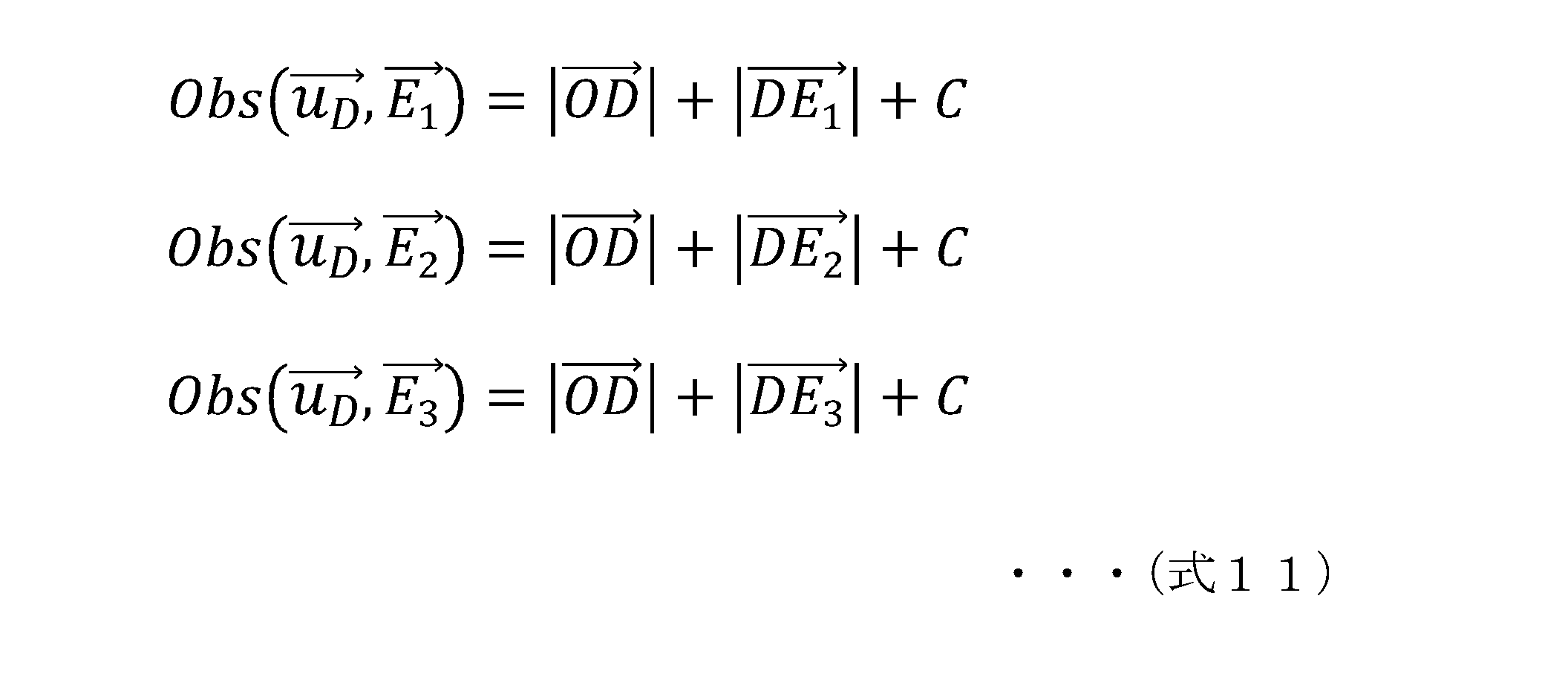
このように、光源位置推定部206は、ステップS201において、光源ユニット10に装着された3つの光源a~cから距離計測装置(カメラ)20までの3つの距離算出式として、
(a)距離計測装置と物体間の距離データ|OD|と、
(b)物体と各光源間の距離データ|DEn|と、
(c)センサクロックと光源クロックの位相差に基づいて発生する距離計測誤差に相当するオフセットC、
これら(a)~(c)のデータからなる3つの距離算出式を算出する。
(a)距離計測装置と物体間の距離データ|OD|と、
(b)物体と各光源間の距離データ|DEn|と、
(c)センサクロックと光源クロックの位相差に基づいて発生する距離計測誤差に相当するオフセットC、
これら(a)~(c)のデータからなる3つの距離算出式を算出する。
図20は、距離計測装置(カメラ)20の光源位置推定部206の詳細構成を示す図である。位相画像メモリ1~3,205は、図10に示す位相画像メモリ205に対応する。図20では、各光源a~c対応の位相画像を格納したメモリとして個別に示している。
このステップS201の処理は、図20に示す位相-距離変換部251において実行される。
このステップS201の処理は、図20に示す位相-距離変換部251において実行される。
(ステップS202)
ステップS202は、すべての光源についての距離情報の取得が完了したか否かを判定するステップである。
すべての光源についての距離情報の取得が完了していない場合は、ステップS201に戻り、未処理の光源についての距離情報取得処理を実行する。
すべての光源についての距離情報取得を完了するとステップS203に進む。
ステップS202は、すべての光源についての距離情報の取得が完了したか否かを判定するステップである。
すべての光源についての距離情報の取得が完了していない場合は、ステップS201に戻り、未処理の光源についての距離情報取得処理を実行する。
すべての光源についての距離情報取得を完了するとステップS203に進む。
(ステップS203)
ステップS203では、複数の注目点(被写体)の光源座標系での位置と、その点の画像上での座標を求める処理を行う。
ステップS203では、複数の注目点(被写体)の光源座標系での位置と、その点の画像上での座標を求める処理を行う。
この処理は、先に説明した図18の(ステップS2~S3)の処理に対応する処理である。
すなわち、まず、(ステップS201)において算出した3つの各光源対応の距離:Obs(uD,E1)、Obs(uD,E2)、Obs(uD,E3)、これらの各距離の差分の算出式からなる連立方程式を生成する。先に説明した以下の(式12)に示す連立方程式である。
すなわち、まず、(ステップS201)において算出した3つの各光源対応の距離:Obs(uD,E1)、Obs(uD,E2)、Obs(uD,E3)、これらの各距離の差分の算出式からなる連立方程式を生成する。先に説明した以下の(式12)に示す連立方程式である。

なお、この差分算出処理は、図20に示す差分計算部252において実行される。
差分計算部252の算出した差分データは、被写体位置計算部253に出力され、被写体位置計算部253が、上記連立方程式を解いて、光源座標系での複数の被写体位置LDkと、対応する画素位置ukを算出する。
差分計算部252の算出した差分データは、被写体位置計算部253に出力され、被写体位置計算部253が、上記連立方程式を解いて、光源座標系での複数の被写体位置LDkと、対応する画素位置ukを算出する。
先に図18を参照して説明したように、カメラ座標からみた各光源位置は未知であるため、この式をカメラ座標系でそのまま解くことはできない。しかし、光源座標系での各光源位置は既知であるため光源座標系であれば解くことができる。
上記の(式12)に示す連立方程式を、光源座標系を用いて解くことで、光源座標系での複数の被写体位置LDkと、対応する画素位置ukを求めることができる。
なお、本例において、複数の被写体位置LDkには、例えば光源ユニット10の各光源a~cの位置E1,E2,E3や、物体30の表面位置が含まれる。
なお、本例において、複数の被写体位置LDkには、例えば光源ユニット10の各光源a~cの位置E1,E2,E3や、物体30の表面位置が含まれる。
(ステップS204~S205)
先に図18を参照して説明したように、一般に、ある座標系での複数の点と、その点がカメラで投影される画素位置の対応関係がわかっていれば、その座標系とカメラ座標系の相対位置姿勢を求めることができる。
先に図18を参照して説明したように、一般に、ある座標系での複数の点と、その点がカメラで投影される画素位置の対応関係がわかっていれば、その座標系とカメラ座標系の相対位置姿勢を求めることができる。
まず、ステップS204において、PnP(Perspective-n-Point Problem)問題を解くことで、光源座標系とカメラ座標系との相対関係を導く。
この処理は、図20に示す光源-カメラ位置関係推定部254が実行する。光源-カメラ位置関係推定部254は、光源座標系光源位置メモリ254に格納された光源座標系光源位置を取得して、PnP(Perspective-n-Point Problem)問題を解くことで、光源座標系とカメラ座標系との相対関係を導き、結果をカメラ-光源座標系相対位置DB256に格納する。この情報は、座標変換部257に出力される。
この処理は、図20に示す光源-カメラ位置関係推定部254が実行する。光源-カメラ位置関係推定部254は、光源座標系光源位置メモリ254に格納された光源座標系光源位置を取得して、PnP(Perspective-n-Point Problem)問題を解くことで、光源座標系とカメラ座標系との相対関係を導き、結果をカメラ-光源座標系相対位置DB256に格納する。この情報は、座標変換部257に出力される。
次に、ステップS205において、光源座標系での被写体位置をカメラ座標系に変換する。この処理は、座標変換部257において実行される。
これらの処理により、カメラ座標系における被写体位置LDkと、対応する画素位置ukを求めることができ、光源a~cの撮影された画素位置から、各光源a~cの位置E1,E2,E3や、物体30の表面位置をカメラ座標系で求めることで、物体30までの距離、すなわち、距離計測装置(カメラ)20と物体までの距離を算出することができる。
なお、この距離(デプス)算出処理を実行するのは、図10を参照して説明した距離計測装置(カメラ)20の距離(デプス)算出部220である。
これらの処理により、カメラ座標系における被写体位置LDkと、対応する画素位置ukを求めることができ、光源a~cの撮影された画素位置から、各光源a~cの位置E1,E2,E3や、物体30の表面位置をカメラ座標系で求めることで、物体30までの距離、すなわち、距離計測装置(カメラ)20と物体までの距離を算出することができる。
なお、この距離(デプス)算出処理を実行するのは、図10を参照して説明した距離計測装置(カメラ)20の距離(デプス)算出部220である。
[7.クロック位相差に基づくオフセット算出処理と、物体の距離(デプス)算出処理を行う場合の具体的処理例について]
次に、図11に示すフローチャートを参照して説明したステップS14の処理、すなわち、クロック位相差に基づくオフセット算出処理と、物体の距離(デプス)算出処理を行う場合の具体的処理例について説明する。
次に、図11に示すフローチャートを参照して説明したステップS14の処理、すなわち、クロック位相差に基づくオフセット算出処理と、物体の距離(デプス)算出処理を行う場合の具体的処理例について説明する。
図11に示すフローのステップS14の処理は、物体30の距離(デプス)の計測処理、すなわち距離計測装置(カメラ)20から物体30までの距離を計測する処理である。さらに、この処理に際して、クロック位相差、すなわち、センサクロックと光源クロックの位相差に基づいて発生する距離計測誤差に相当するオフセットCの算出処理を実行する。
なお、この処理は光源ユニット10が2つの光源からなる構成であっても実行可能な処理である。すなわち光源ユニット10は2つ以上の複数の光源を備えていればよい。
なお、この処理は光源ユニット10が2つの光源からなる構成であっても実行可能な処理である。すなわち光源ユニット10は2つ以上の複数の光源を備えていればよい。
この処理の具体例について、図21以下を参照して説明する。
光源ユニット10側のクロックと、距離計測装置(カメラ)20側のクロックとの位相差算出処理は、以下の前提の下で実行される。
(a)光源ユニット10の各光源位置は、カメラ座標系で既知である。
(b)光源ユニット10の光源ユニットクロックと、距離計測装置(カメラ)20側のセンサクロックの周波数はほぼ一致、または推定されている。
光源ユニット10側のクロックと、距離計測装置(カメラ)20側のクロックとの位相差算出処理は、以下の前提の下で実行される。
(a)光源ユニット10の各光源位置は、カメラ座標系で既知である。
(b)光源ユニット10の光源ユニットクロックと、距離計測装置(カメラ)20側のセンサクロックの周波数はほぼ一致、または推定されている。
これらの前提条件の下、距離計測装置(カメラ)20側のクロックとの位相差算出処理を実行し、さらに、物体30等の被写体距離の算出を行う。
なお、クロック位相差算出処理を実行するのは、図10に示す距離計測装置(カメラ)20のクロック位相差(光源クロックオフセット)算出部208であり、距離算出を行うのは、距離(デプス)算出部220である。
なお、クロック位相差算出処理を実行するのは、図10に示す距離計測装置(カメラ)20のクロック位相差(光源クロックオフセット)算出部208であり、距離算出を行うのは、距離(デプス)算出部220である。
なお、クロック位相差(光源クロックオフセット)算出部208は、距離計測装置(カメラ)20側のクロックとの位相差、または、位相差に基づく距離計測誤差に相当するオフセットCを算出する。距離(デプス)算出部220は、このオフセットCを適用して物体30までの距離を算出する。
オフセットCは、センサクロック201と光源ユニットクロック101の位相差に基づく距離算出時の誤差量に相当するオフセットCであり、先に図17を参照して説明した(ステップS1)で利用した式11のオフセットCと同様の値である。
距離計測装置(カメラ)20側のクロックとの位相差算出処理と、物体30等の被写体距離算出処理は、光源ユニット10の2つの光源からの発光パルスのみを用いて実行することができる。
前述したように、この処理は光源ユニット10が3つの光源を有することなく、2つの光源のみの構成であっても実行可能な処理である。
前述したように、この処理は光源ユニット10が3つの光源を有することなく、2つの光源のみの構成であっても実行可能な処理である。
図21には、光源ユニット10の2つの光源a,bのみを示している。
光源a,bは位置E1に位置する光源aと、位置E2に位置する光源bである。なお、位置は、図21に示す距離計測装置(カメラ)20の位置に原点Oを持つカメラ座標系で取得されているものとする。
光源a,bは位置E1に位置する光源aと、位置E2に位置する光源bである。なお、位置は、図21に示す距離計測装置(カメラ)20の位置に原点Oを持つカメラ座標系で取得されているものとする。
図21右側には、クロック位相差(光源クロックオフセット)算出部208と距離(デプス)算出部220の実行する(1)距離(デプス)算出処理の概要を示している。
まず、(ステップS1)において、光源ユニット10の2つの光源a,bが発光するパルスの受光パルスに基づいて取得されるフレームを用いて距離(各光源a,bから距離計測装置(カメラ)20間の距離)を算出する。
まず、(ステップS1)において、光源ユニット10の2つの光源a,bが発光するパルスの受光パルスに基づいて取得されるフレームを用いて距離(各光源a,bから距離計測装置(カメラ)20間の距離)を算出する。
この各光源a,bから距離計測装置(カメラ)20間の距離は、以下の(式21)によって表される。

なお、上記(式21)におけるベクトル表記パラメータ(各パラメータの上部に→を表記したパラメータ)は、ある1つの座標系、例えばカメラ座標系の原点からのベクトルを示す。また、上記(式21)における各パラメータは以下の意味を有する。
Cは光源ユニット10と距離計測装置(カメラ)20のクロックの位相ズレに起因する計測距離誤差に相当するオフセット項、
Obs(uD,E1)は、位置E1に位置する光源aが発光したときに画素位置uDにて観測される距離、
Obs(uD,E2)は、位置E2に位置する光源bが発光したときに画素位置uDにて観測される距離、
uD=(uD,vD)は点Dが投影される画素位置
|OD|は、距離計測装置(カメラ)20と物体30とを結ぶベクトルの大きさ(距離)。なお、Oは距離計測装置(カメラ)20の座標系であるカメラ座標系の原点である。Dは光源からの光の物体30における反射位置である。
|DEn|は、位置Enにある各光源と物体30における反射位置とを結ぶベクトルの大きさ(距離)
である。
なお、上記式の説明においてベクトル表記は省略している。
Cは光源ユニット10と距離計測装置(カメラ)20のクロックの位相ズレに起因する計測距離誤差に相当するオフセット項、
Obs(uD,E1)は、位置E1に位置する光源aが発光したときに画素位置uDにて観測される距離、
Obs(uD,E2)は、位置E2に位置する光源bが発光したときに画素位置uDにて観測される距離、
uD=(uD,vD)は点Dが投影される画素位置
|OD|は、距離計測装置(カメラ)20と物体30とを結ぶベクトルの大きさ(距離)。なお、Oは距離計測装置(カメラ)20の座標系であるカメラ座標系の原点である。Dは光源からの光の物体30における反射位置である。
|DEn|は、位置Enにある各光源と物体30における反射位置とを結ぶベクトルの大きさ(距離)
である。
なお、上記式の説明においてベクトル表記は省略している。
このように、距離(デプス)算出部220は、(ステップS1)において、光源ユニット10に装着された2つの光源a~bから距離計測装置(カメラ)20までの2つの距離算出式として、
(a)距離計測装置と物体間の距離データ|OD|と、
(b)物体と各光源間の距離データ|DEn|と、
(c)センサクロックと光源クロックの位相差に基づいて発生する距離計測誤差に相当するオフセットC、
これら(a)~(c)のデータからなる2つの距離算出式を算出する。
(a)距離計測装置と物体間の距離データ|OD|と、
(b)物体と各光源間の距離データ|DEn|と、
(c)センサクロックと光源クロックの位相差に基づいて発生する距離計測誤差に相当するオフセットC、
これら(a)~(c)のデータからなる2つの距離算出式を算出する。
次に、(ステップS2)において、ステップS1で算出した2つの各距離:Obs(uD,E1)、Obs(uD,E2)、これらの距離の差分の算出式を生成する。以下の(式22)に示す差分算出式である。
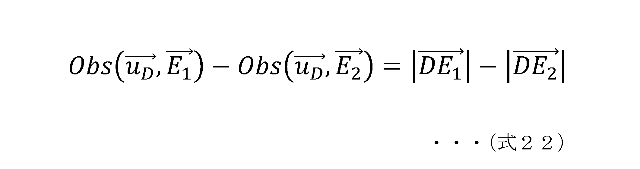
この差分算出式を生成することで、(ステップS1)において生成した距離算出式に含まれるオフセット項C、すなわち、光源ユニット10と距離計測装置(カメラ)20のクロックの位相ズレに起因する計測距離誤差に相当するオフセット項Cを消去できる。
次に、(ステップS3)において、物体30までの距離、すなわち、距離計測装置(カメラ)20と物体30との距離Dを算出する。
この処理においては、まず、距離計測装置(カメラ)20の原点Oから、物体30の表面DまでのベクトルOD方向の単位ベクトルdを求めて、以下の(式23)を生成する。
この処理においては、まず、距離計測装置(カメラ)20の原点Oから、物体30の表面DまでのベクトルOD方向の単位ベクトルdを求めて、以下の(式23)を生成する。
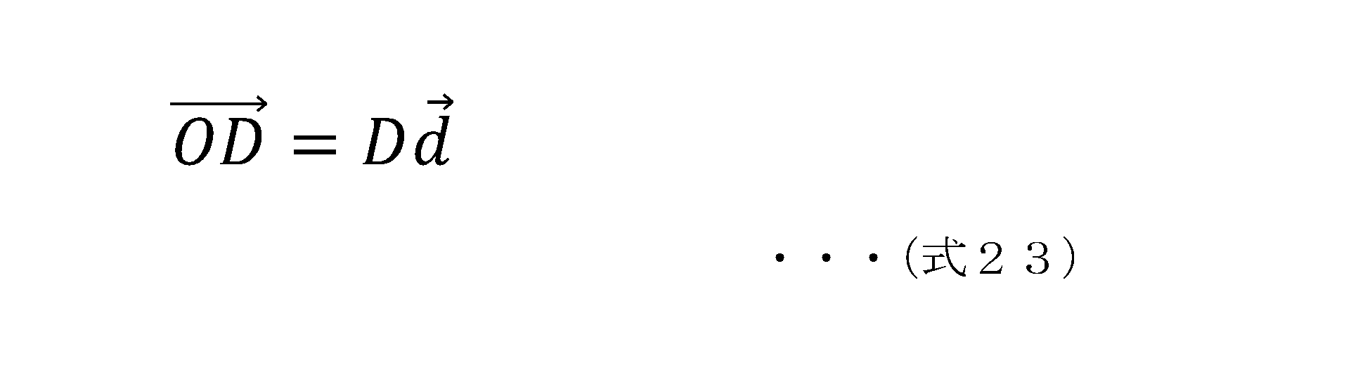
この(式23)は、距離計測装置(カメラ)20から物体30を結ぶ直線方程式である。
このように、距離(デプス)算出部220は、(ステップS3)において、
(d)距離計測装置(カメラ)20と物体30間を結ぶ直線方程式を生成する。
このように、距離(デプス)算出部220は、(ステップS3)において、
(d)距離計測装置(カメラ)20と物体30間を結ぶ直線方程式を生成する。
次に、この(式23)と、先に(ステップS2)で生成した距離の差分算出式(式22)を用いて、物体30の表面Dの位置(x,y,z)を算出し、この位置(x,y,z)に基づいて距離Dを算出する。
ステップS1~S3の処理をまとめると以下の処理となる。
距離(デプス)算出部220は、(ステップS1)において、光源ユニット10に装着された少なくとも2つの光源から距離計測装置(カメラ)20までの2つの距離算出式として、
(a)前記距離計測装置と前記物体間の距離データと、
(b)前記物体と、前記光源ユニットの各光源間の距離データと、
(c)前記センサクロックと前記光源クロックの位相差に基づいて発生する距離計測誤差に相当するオフセットC、
これら(a)~(c)のデータからなる2つの距離算出式を生成する。
さらに、(ステップS2)において、距離算出式各々の差分を算出する1つの差分算出式を生成する。
距離(デプス)算出部220は、(ステップS1)において、光源ユニット10に装着された少なくとも2つの光源から距離計測装置(カメラ)20までの2つの距離算出式として、
(a)前記距離計測装置と前記物体間の距離データと、
(b)前記物体と、前記光源ユニットの各光源間の距離データと、
(c)前記センサクロックと前記光源クロックの位相差に基づいて発生する距離計測誤差に相当するオフセットC、
これら(a)~(c)のデータからなる2つの距離算出式を生成する。
さらに、(ステップS2)において、距離算出式各々の差分を算出する1つの差分算出式を生成する。
さらに、(ステップS3)において、
(d)前記距離計測装置と前記物体間を結ぶ直線方程式を生成し、
差分算出式と、直線方程式を連立方程式として解いて、距離計測装置(カメラ)20と物体30との距離を算出する
(d)前記距離計測装置と前記物体間を結ぶ直線方程式を生成し、
差分算出式と、直線方程式を連立方程式として解いて、距離計測装置(カメラ)20と物体30との距離を算出する
この処理について、図22を参照して説明する。
(ステップS2)で生成した距離の差分算出式(式22)は、光源a,bの位置E1と位置E2を焦点とする二葉双曲面の片側を示す方程式に相当する。本稿では以下簡単のため単に双曲面と記述する。
一方、(ステップS3)で生成した(式23)は、距離計測装置(カメラ)20の原点Oと、物体30の表面Dを結ぶ直線を示す方程式に相当する。
(ステップS2)で生成した距離の差分算出式(式22)は、光源a,bの位置E1と位置E2を焦点とする二葉双曲面の片側を示す方程式に相当する。本稿では以下簡単のため単に双曲面と記述する。
一方、(ステップS3)で生成した(式23)は、距離計測装置(カメラ)20の原点Oと、物体30の表面Dを結ぶ直線を示す方程式に相当する。
図22(A)に示すように、
双曲面の方程式に相当する差分算出式(式22)と、
直線方程式に相当する(式23)、
これら2つの式を連立方程式として解くと、図22(B1)に示すように、2つの式を満たす点、すなわち交点が算出できる。
図22(B1)に示すように、この交点は、物体30の表面の位置Dの位置(x,y,z)となる。
双曲面の方程式に相当する差分算出式(式22)と、
直線方程式に相当する(式23)、
これら2つの式を連立方程式として解くと、図22(B1)に示すように、2つの式を満たす点、すなわち交点が算出できる。
図22(B1)に示すように、この交点は、物体30の表面の位置Dの位置(x,y,z)となる。
このように、双曲面の方程式に相当する差分算出式(式22)と、
直線方程式に相当する(式23)、
これら2つの式を連立方程式として解くことで、物体30の表面Dの位置(x,y,z)を算出することが可能となる。この位置(x,y,z)はカメラ座標系の位置を示す座標であり、この位置(x,y,z)に基づいて、カメラ座標系の原点Oからの距離Dを算出することができる。
直線方程式に相当する(式23)、
これら2つの式を連立方程式として解くことで、物体30の表面Dの位置(x,y,z)を算出することが可能となる。この位置(x,y,z)はカメラ座標系の位置を示す座標であり、この位置(x,y,z)に基づいて、カメラ座標系の原点Oからの距離Dを算出することができる。
なお、図22(B2)に示すように、双曲面の方程式に相当する差分算出式(式22)と、直線方程式に相当する(式23)による交点が2つ検出されてしまう可能性があり、一般的にはどちらが真の位置か特定することは出来ない。しかしこの問題はカメラ、光源の相対位置を変えることでさけることができる(後述)。あるいは、各点光源に遮光板等をつけ、カメラ方向(あるいはカメラと逆方向)にのみ投光することで、重解のうちどちらが真の位置か特定することができる。
なお、一般的にある点A,点Bから点Pの距離を|AP|,|BP|としたとき、|AP|-|BP|が一定となる点Pの集合は双曲面の一部となる。すなわち、前述の差分算出式(式22)は双曲面の一部を示す式となる。
例えば、図23に示すように点Aの座標を(0,0,c)、点B(0,0,-c)、|AP|-|BP|=2eとすると点Pは、下記(式24)を満たす。
例えば、図23に示すように点Aの座標を(0,0,c)、点B(0,0,-c)、|AP|-|BP|=2eとすると点Pは、下記(式24)を満たす。

なお、上記(式24)が表す図形は、図23の双曲面を示す図中の+z方向と-z方向の2つの曲面に分かれるが、これは|AP|-|BP|=-2eとなる場合も同じ上記(式24)が得られるためであり、|AP|-|BP|の符号が分かって入ればどちらか片方に特定される。
前述の差分算出式(式22)も、この問題と同等であるため、(式22)が表す図形は、(二葉)双曲面の片側となる。
前述の差分算出式(式22)も、この問題と同等であるため、(式22)が表す図形は、(二葉)双曲面の片側となる。
このように、距離(デプス)算出部220は、双曲面の方程式に相当する差分算出式(式22)と、直線方程式に相当する(式23)、これら2つの式を連立方程式として解き、物体30の表面Dの位置(x,y,z)を算出し、さらに、算出した位置(x,y,z)に基づいて、カメラ座標系の原点Oからの距離Dを算出する。
次に、図24、図25を参照して、距離計測装置(カメラ)20のクロック位相差(光源クロックオフセット)算出部208と距離(デプス)算出部220の詳細構成と、クロック位相差算出処理と被写体位置算出処理(=距離算出処理)の処理シーケンスについて説明する。
図24は、クロック位相差算出処理と被写体位置算出処理(=距離算出処理)の処理シーケンスを説明するフローチャートである。
図25は、先に図10を参照して説明した距離計測装置(カメラ)20のクロック位相差(光源クロックオフセット)算出部208と距離(デプス)算出部220の詳細構成を示す図である。
図24は、クロック位相差算出処理と被写体位置算出処理(=距離算出処理)の処理シーケンスを説明するフローチャートである。
図25は、先に図10を参照して説明した距離計測装置(カメラ)20のクロック位相差(光源クロックオフセット)算出部208と距離(デプス)算出部220の詳細構成を示す図である。
図25に示す構成中、クロック位相差(光源クロックオフセット)算出部208以外の位相-距離変換部271~被写体位置計算部275の構成は、距離(デプス)算出部220の構成要素である。内部パラメータメモリ273は、距離(デプス)算出部220がアクセス可能な距離計測装置(カメラ)20内のメモリであり、例えば事前に実行されるカメラのキャリブレーション処理によって得られたカメラパラメータ等が格納されている。
図24のフローチャートの各ステップの処理について、図25に示す構成図を参照しながら説明する。
(ステップS301)
まず、ステップS301において、光源ユニット10の2つの光源a,bいずれか1つの光源からの出力光、すなわち発光パルスの受光パルスに基づいて取得されるフレームを用いて距離(光源から距離計測装置(カメラ)20間の距離)を算出する。
(ステップS301)
まず、ステップS301において、光源ユニット10の2つの光源a,bいずれか1つの光源からの出力光、すなわち発光パルスの受光パルスに基づいて取得されるフレームを用いて距離(光源から距離計測装置(カメラ)20間の距離)を算出する。
このステップS301の処理は、図25に示す位相-距離変換部271において実行される。
(ステップS302)
ステップS302は、2つの光源についての距離情報の取得が完了したか否かを判定するステップである。
2つの光源についての距離情報の取得が完了していない場合は、ステップS301に戻り、未処理の光源についての距離情報取得処理を実行する。
2つの光源についての距離情報取得を完了するとステップS303に進む。
ステップS302は、2つの光源についての距離情報の取得が完了したか否かを判定するステップである。
2つの光源についての距離情報の取得が完了していない場合は、ステップS301に戻り、未処理の光源についての距離情報取得処理を実行する。
2つの光源についての距離情報取得を完了するとステップS303に進む。
このステップS302の処理において2つの光源の距離情報取得完了と判断された場合は、2つの光源から距離計測装置(カメラ)20間の距離算出式として、先に説明した以下の(式21)によって表される式の距離情報が取得されたことになる。

図25は、距離計測装置(カメラ)20のクロック位相差(光源クロックオフセット)算出部208と距離(デプス)算出部220の詳細構成を示す図である。位相画像メモリ1~2,205は、図10に示す位相画像メモリ205に対応する。図25では、各光源a,b対応の位相画像を格納したメモリとして個別に示している。
(ステップS303)
次に、(ステップS301)において算出した2つの各光源対応の距離:Obs(uD,E1)、Obs(uD,E2)、これらの各距離の差分算出式を生成する。先に説明した以下の(式22)に示す差分算出式である。
次に、(ステップS301)において算出した2つの各光源対応の距離:Obs(uD,E1)、Obs(uD,E2)、これらの各距離の差分算出式を生成する。先に説明した以下の(式22)に示す差分算出式である。

なお、この差分算出処理は、図25に示す差分計算部272において実行される。
差分計算部272の算出した差分データは、被写体位置計算部275に出力される。
差分計算部272の算出した差分データは、被写体位置計算部275に出力される。
(ステップS304)
次に、ステップS304において、既知条件、既知パラメータを用いて、ステップS303で生成した差分算出式を満たす双曲面方程式を生成する。
次に、ステップS304において、既知条件、既知パラメータを用いて、ステップS303で生成した差分算出式を満たす双曲面方程式を生成する。
先に説明したようように前述の差分算出式(式22)は双曲面の一部を示す式となる。すなわち、図23に示すように点Aの座標を(0,0,c)、点B(0,0,-c)、|AP|-|BP|=2eとすると点Pは、先に説明した(式24)を満たし、(式24)が表す図形は、図23の双曲面を示す図中の+z方向と-z方向の2つの曲面に分かれる。
これは|AP|-|BP|=-2eとなる場合も同じ上記(式24)が得られるためであり、|AP|-|BP|の符号が分かって入ればどちらか片方に特定される。
前述の差分算出式(式22)も、この問題と同等であるため、(式22)が表す図形は、(二葉)双曲面の片側となる。
ステップS304では、上記の既知条件、既知パラメータを用いて、ステップS303で生成した差分算出式を満たす双曲面方程式を生成する。
この処理は、図25に示す被写体位置計算部275が実行する。
これは|AP|-|BP|=-2eとなる場合も同じ上記(式24)が得られるためであり、|AP|-|BP|の符号が分かって入ればどちらか片方に特定される。
前述の差分算出式(式22)も、この問題と同等であるため、(式22)が表す図形は、(二葉)双曲面の片側となる。
ステップS304では、上記の既知条件、既知パラメータを用いて、ステップS303で生成した差分算出式を満たす双曲面方程式を生成する。
この処理は、図25に示す被写体位置計算部275が実行する。
(ステップS305)
次に、ステップS305において、既知条件、既知パラメータを用いて、距離計測装置(カメラ)20から、物体30の表面DまでのベクトルOD方向の単位ベクトルdを求めて、単位ベクトルdを含む直線方程式、すなわち、先に説明した(式23)に示す直線方程式を生成する。
なお、一般的に、ある空間上の点(x,y,z)が、カメラ上に投影される画素位置を(u,v)とすると、これらの位置関係は以下の(式25)のように定義される。
次に、ステップS305において、既知条件、既知パラメータを用いて、距離計測装置(カメラ)20から、物体30の表面DまでのベクトルOD方向の単位ベクトルdを求めて、単位ベクトルdを含む直線方程式、すなわち、先に説明した(式23)に示す直線方程式を生成する。
なお、一般的に、ある空間上の点(x,y,z)が、カメラ上に投影される画素位置を(u,v)とすると、これらの位置関係は以下の(式25)のように定義される。
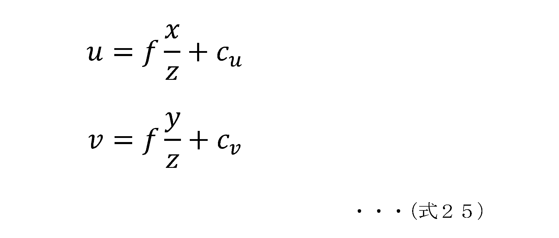
なお、f,cv,cuは、予め求めることができるレンズのパラメータ(内部パラメータ)であり、図25に示す内部パラメータメモリ273に格納されている。
一方、カメラ上に投影される画素位置(u,v)が与えられれば、その画素位置が観察している視線方向(視線ベクトル)を推定することができる。すなわち、以下の(式26)が成立する。

上記の(式26)を解くことで、ベクトルOD方向の視線ベクトルに相当する単位ベクトルdを求めることができる。
この処理によって、距離計測装置(カメラ)20から、物体30の表面DまでのベクトルOD方向の単位ベクトルdを求めて、単位ベクトルdを含む直線方程式、すなわち、以下に示す先に説明した(式23)に示す直線方程式を生成する。
この処理によって、距離計測装置(カメラ)20から、物体30の表面DまでのベクトルOD方向の単位ベクトルdを求めて、単位ベクトルdを含む直線方程式、すなわち、以下に示す先に説明した(式23)に示す直線方程式を生成する。
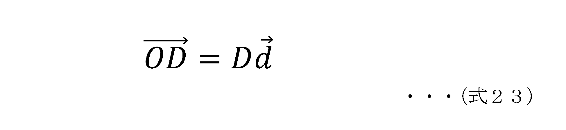
なお、この処理は、図25に示す視線ベクトル算出部274と、被写体位置計算部275において実行される。
(ステップS306)
最後に、ステップS306において、ステップS303~S304で生成した双曲面方程式と、ステップS305で生成した直線方程式からなる連立方程式を解き、双曲面と直線との交点位置を算出し、算出した交点位置に基づいて、距離計測装置(カメラ)20から、物体30の表面までの距離Dを算出する。
最後に、ステップS306において、ステップS303~S304で生成した双曲面方程式と、ステップS305で生成した直線方程式からなる連立方程式を解き、双曲面と直線との交点位置を算出し、算出した交点位置に基づいて、距離計測装置(カメラ)20から、物体30の表面までの距離Dを算出する。
この処理は、先に図22を参照して説明した双曲面と直線との交点位置の算出処理である。すなわち、双曲面の方程式に相当する差分算出式(式22)と、直線方程式に相当する(式23)、これら2つの式から構成される以下の連立方程式を取得する処理である。

上記の連立方程式として解くことで、物体30の表面Dの位置(x,y,z)を算出する。この位置(x,y,z)はカメラ座標系の位置を示す座標であり、この位置(x,y,z)に基づいて、カメラ座標系の原点Oからの距離Dを算出することができる。
このステップS306の処理は、図25に示す被写体位置計算部275において実行される。
このようにして、物体30までの距離を算出することができる。
このようにして、物体30までの距離を算出することができる。
なお、フローには示していないが、この距離算出処理に際して、図25に示すクロック位相差(光源クロックオフセット)算出部208は、さらに、ステップS301~S302において生成した距離算出式、すなわち、以下の(式21)の距離算出式に含まれるオフセットC、すなわち、センサクロックと光源クロックの位相差に基づいて発生する距離計測誤差の値を算出して、クロック位相差(光源クロックオフセット)メモリ209に格納する。
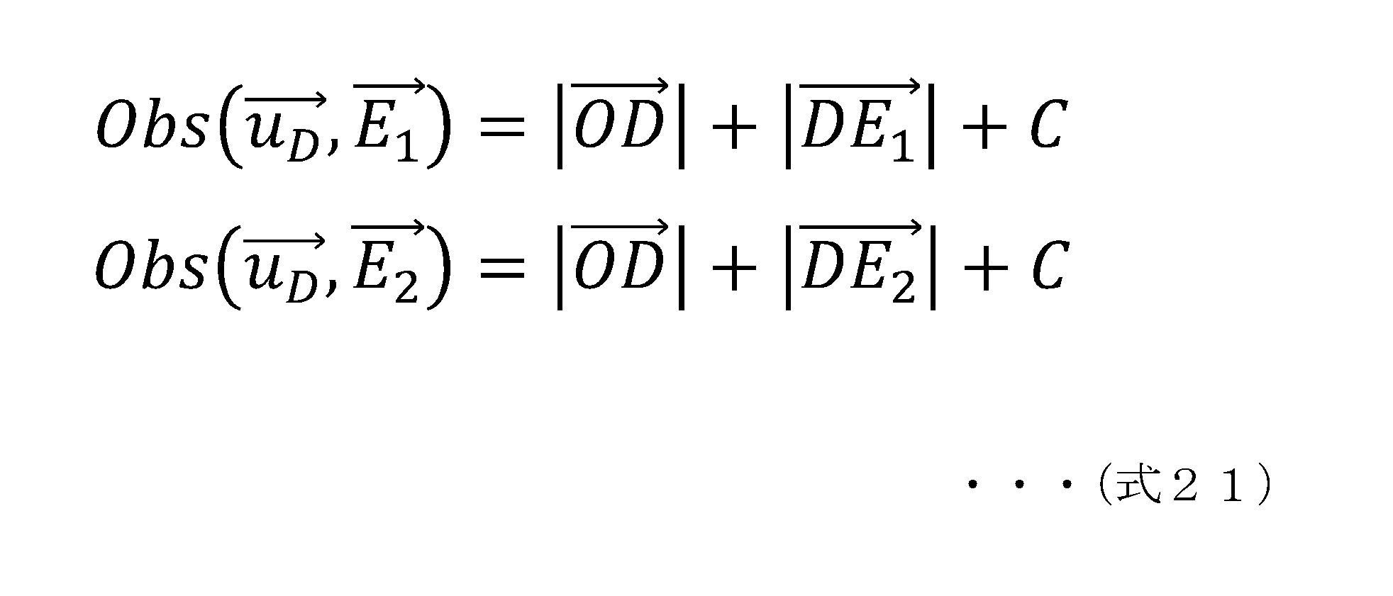
オフセットCの値は固定的な値であるので、その後の距離算出処理おいて利用可能となる。
なお、物体30の位置や距離は、図24に示すフローに従った処理によって算出済みであり、また、光源位置も取得済みであるので、これらの値から、上記(式21)の距離算出式を用いてオフセットCの値を算出することができる。
なお、オフセットCの値が算出できれば、オフセットCの値に基づいてセンサクロックと光源クロックの位相差も算出可能であり、算出した位相差を、オフセットCの値とともに、クロック位相差(光源クロックオフセット)メモリ209に格納する構成としてもよい。
なお、物体30の位置や距離は、図24に示すフローに従った処理によって算出済みであり、また、光源位置も取得済みであるので、これらの値から、上記(式21)の距離算出式を用いてオフセットCの値を算出することができる。
なお、オフセットCの値が算出できれば、オフセットCの値に基づいてセンサクロックと光源クロックの位相差も算出可能であり、算出した位相差を、オフセットCの値とともに、クロック位相差(光源クロックオフセット)メモリ209に格納する構成としてもよい。
[8.光源位置、光源クロックオフセットが既知の場合に、物体の距離(デプス)を算出する処理の具体例について]
次に、光源位置、光源クロックオフセットが既知の場合に、物体の距離(デプス)を算出する処理の具体例について説明する。
次に、光源位置、光源クロックオフセットが既知の場合に、物体の距離(デプス)を算出する処理の具体例について説明する。
この処理は、図12(b)に示すフローチャートのステップS31の処理に相当する。
図12(b)に示すフローのステップS31の処理は、クロック位相差、すなわちセンサクロックと光源クロックの位相差に基づくオフセットC、すなわち、クロック位相差に基づく距離計測誤差の値を適用して物体の距離(デプス)を計測する処理である。先に説明したように、この図12(b)に示すフローに従った処理は、既にクロック位相差に基づくオフセットCが算出され、メモリに格納されている場合に実行されるフローである。
図12(b)に示すフローのステップS31の処理は、クロック位相差、すなわちセンサクロックと光源クロックの位相差に基づくオフセットC、すなわち、クロック位相差に基づく距離計測誤差の値を適用して物体の距離(デプス)を計測する処理である。先に説明したように、この図12(b)に示すフローに従った処理は、既にクロック位相差に基づくオフセットCが算出され、メモリに格納されている場合に実行されるフローである。
すなわち、例えば、前述した図21~図25を参照して説明した処理において、クロック位相差(光源クロックオフセット)算出部208が、オフセットCの値をクロック位相差(光源クロックオフセット)メモリ209に格納した後に行われる距離算出処理である。
なお、先に説明したように、オフセットCは、センサクロックと光源クロックの位相差に基づいて発生する距離計測誤差の値に相当する。
なお、先に説明したように、オフセットCは、センサクロックと光源クロックの位相差に基づいて発生する距離計測誤差の値に相当する。
この処理の具体例について、図26以下を参照して説明する。
この処理では、距離(デプス)算出部220が、図26の右側に示す2つの式の連立方程式を解くことで、物体30までの距離を算出する。
すなわち、以下の(式31)に示す連立方程式である。
この処理では、距離(デプス)算出部220が、図26の右側に示す2つの式の連立方程式を解くことで、物体30までの距離を算出する。
すなわち、以下の(式31)に示す連立方程式である。

上記(式31)の連立方程式は、光源aから距離計測装置(カメラ)20間の距離算出式と、距離計測装置(カメラ)20から物体30表面までのベクトルOD方向の単位ベクトルdを含む直線方程式の2つの式によって構成される。
光源aから距離計測装置(カメラ)20間の距離算出式は、先に説明した(式11)や(式21)に含まれる式と同じであり、
Obs(uD,E1)は、位置E1に位置する光源aが発光したときに画素位置uDにて観測される距離、
uD=(uD,vD)は点Dが投影される画素位置
また、Cは、オフセット項であり、センサクロックと光源クロックの位相差に基づいて発生する距離計測誤差の値に相当する。本処理例において、このオフセットCの値は既知である。
単位ベクトルdを含む直線方程式は、先に説明した(式23)と同じ式である。
Obs(uD,E1)は、位置E1に位置する光源aが発光したときに画素位置uDにて観測される距離、
uD=(uD,vD)は点Dが投影される画素位置
また、Cは、オフセット項であり、センサクロックと光源クロックの位相差に基づいて発生する距離計測誤差の値に相当する。本処理例において、このオフセットCの値は既知である。
単位ベクトルdを含む直線方程式は、先に説明した(式23)と同じ式である。
図27は、この処理を実行する距離(デプス)算出部220の詳細構成を示す図である。図27を参照して、これらの連立方程式の生成処理と、連立方程式を解いて物体30までの距離を算出する距離(デプス)算出部220の実行する処理について説明する。
まず、位相-距離変換部282が、光源ユニット10の1つの光源aからの出力光、すなわち発光パルスの受光パルスに基づいて取得されるフレームを用いて距離(光源から距離計測装置(カメラ)20間の距離)を算出する。
この算出式が、上記(式31)のObs(uD,E1)を算出する距離算出式である。なお、この距離算出式に含まれるオフセットCは、センサクロックと光源クロックの位相差に基づいて発生する距離計測誤差の値であり、図27に示すクロック位相差(光源クロックオフセット)メモリ209に格納された既知の値である。
この算出式が、上記(式31)のObs(uD,E1)を算出する距離算出式である。なお、この距離算出式に含まれるオフセットCは、センサクロックと光源クロックの位相差に基づいて発生する距離計測誤差の値であり、図27に示すクロック位相差(光源クロックオフセット)メモリ209に格納された既知の値である。
一方、視線ベクトル算出部281と被写体位置計算部283は、既知条件、既知パラメータを用いて、距離計測装置(カメラ)20から、物体30の表面DまでのベクトルOD方向の単位ベクトルdを求めて、単位ベクトルdを含む直線方程式、すなわち、上記の(式31)に含まれる直線方程式を生成する。
この処理は、先に図24を参照して説明したフローのステップS305の処理と同じ処理である。
次に、被写体位置計算部283は、位相-距離変換部282が生成した距離算出式と、単位ベクトルdを含む直線方程式から構成される連立方程式、すなわち、上述した(式31)の連立方程式を解いて、物体30の表面Dの3次元位置を求めて、カメラ座標系の原点Oからの距離Dを算出する。なお、これらの処理において利用する光源位置情報は、光源ユニット位置姿勢メモリ207から取得し、オフセットCの値は、クロック位相差(光源クロックオフセット)メモリ209から取得する。
[9.双曲面方程式と直線方程式との連立方程式の解に重解を発生させない構成について]
次に、双曲面方程式と直線方程式との連立方程式の解に重解を発生させない構成について説明する。
次に、双曲面方程式と直線方程式との連立方程式の解に重解を発生させない構成について説明する。
先に図22を参照して説明したように、物体30の距離を求めるための処理として、以下の連立方程式を解いて、双曲面と直線との交点を算出する処理について説明した。

すなわち、2つの光源からの距離算出式の差分算出式である(式22)と、距離計測装置(カメラ)20から物体30を結ぶ直線方程式、すなわち、距離計測装置(カメラ)20の原点Oから、物体30の表面DまでのベクトルOD方向の単位ベクトルdを含む直線方程式である(式23)によって構成される連立方程式である。
先に図22を参照して説明したように、双曲面の方程式に相当する差分算出式(式22)と、
直線方程式に相当する(式23)、
これら2つの式を連立方程式として解くと、図22(B1)に示すように、2つの式を満たす点、すなわち交点が算出できる。
図22(B1)に示すように、この交点は、物体30の表面の位置Dの位置(x,y,z)となる。
直線方程式に相当する(式23)、
これら2つの式を連立方程式として解くと、図22(B1)に示すように、2つの式を満たす点、すなわち交点が算出できる。
図22(B1)に示すように、この交点は、物体30の表面の位置Dの位置(x,y,z)となる。
このように2つの式を連立方程式として解くことで、物体30の表面Dの位置(x,y,z)を算出することが可能となる。この位置(x,y,z)はカメラ座標系の位置を示す座標であり、この位置(x,y,z)に基づいて、カメラ座標系の原点Oからの距離Dを算出することができる。
しかし、図22(B2)に示すように、双曲面の方程式に相当する差分算出式(式22)と、直線方程式に相当する(式23)による交点が2つ検出されてしまう、すなわち連立方程式に複数の解、いわゆる重解が発生する可能性がある。
以下では、このような重解を発生させないための被写体、すなわち距離計測対象となる物体の配置制限について説明する。
以下では、このような重解を発生させないための被写体、すなわち距離計測対象となる物体の配置制限について説明する。
図28は、重解を発生させないための物体30の配置制限例の一例を示す図である。
図28に示すように、予め被写体、すなわち距離計測対象となる物体の物体(被写体)存在許容領域301を規定する。
図28に示すように、予め被写体、すなわち距離計測対象となる物体の物体(被写体)存在許容領域301を規定する。
次に、この物体(被写体)存在許容領域301の端点に接する双曲面302を求める。この際、双曲面302が物体(被写体)存在許容領域301の端点に接し、かつ以下の式(式41)によって定義されるkの絶対値が最大値となる面を算出する。
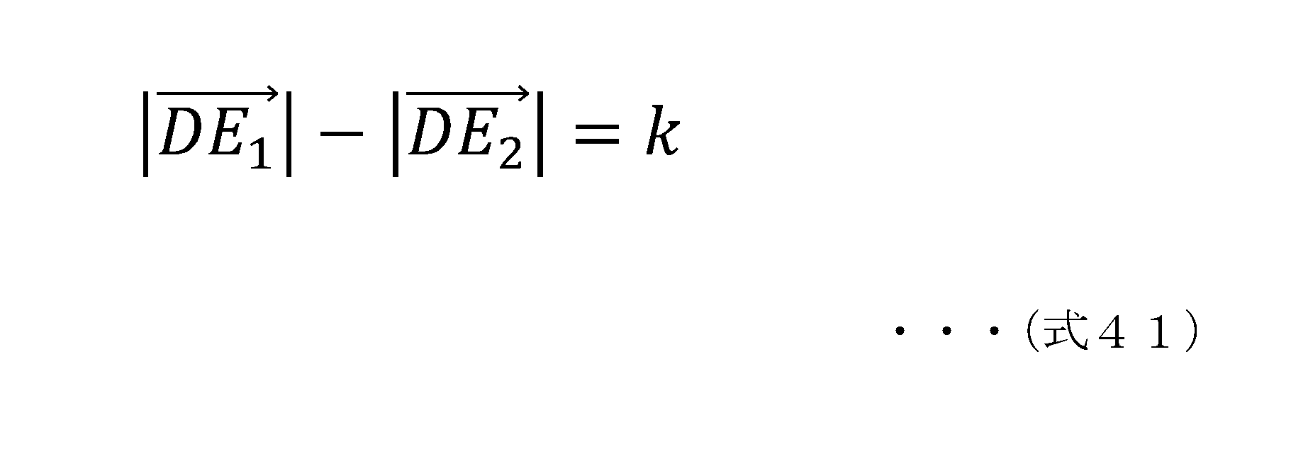
上記(式41)によって算出される値kは、物体30と光源aとの距離と、物体30と光源bとの距離の差分に相当する。
この条件で定義される双曲面の内側領域にカメラ、すなわち、図に示すような位置に距離計測装置(カメラ)20を配置する。
このような設定とすることで、双曲面の方程式に相当する差分算出式(式22)と、直線方程式に相当する(式23)との連立方程式に重解が発生しない、すなわち、交点が2つ検出されることのない設定とすることができる。
この条件で定義される双曲面の内側領域にカメラ、すなわち、図に示すような位置に距離計測装置(カメラ)20を配置する。
このような設定とすることで、双曲面の方程式に相当する差分算出式(式22)と、直線方程式に相当する(式23)との連立方程式に重解が発生しない、すなわち、交点が2つ検出されることのない設定とすることができる。
図29は、連立方程式に重解を発生させないための図28と異なる条件設定例である。
図29に示す例は、光源a,bとカメラ、すなわち距離計測装置(カメラ)20を以下の条件を満たす配置とする配置制限例である。
(条件A)光源a,bとカメラ、すなわち距離計測装置(カメラ)20を一直線上に並べる。
(条件B)距離計測装置(カメラ)20の光軸(撮影方向)を上記直線から傾ける。
図29に示す例は、光源a,bとカメラ、すなわち距離計測装置(カメラ)20を以下の条件を満たす配置とする配置制限例である。
(条件A)光源a,bとカメラ、すなわち距離計測装置(カメラ)20を一直線上に並べる。
(条件B)距離計測装置(カメラ)20の光軸(撮影方向)を上記直線から傾ける。
これらの条件A,Bを満足するように光源と距離計測装置(カメラ)20を配置することで、双曲面の方程式に相当する差分算出式(式22)と、直線方程式に相当する(式23)との連立方程式に重解が発生しない、すなわち、交点が2つ検出されることのない設定とすることができる。
例えば図29に示す物体(被写体)存在許容領域303に距離計測対象となる物体30を配置することができる。
例えば図29に示す物体(被写体)存在許容領域303に距離計測対象となる物体30を配置することができる。
[10.複数の光源ユニットを利用した構成例について]
次に、複数の光源ユニットを利用した構成例について説明する。本開示の距離計測システムの特徴として、光源ユニットを距離計測装置(カメラ)と独立した構成とすることができるという特徴がある。
次に、複数の光源ユニットを利用した構成例について説明する。本開示の距離計測システムの特徴として、光源ユニットを距離計測装置(カメラ)と独立した構成とすることができるという特徴がある。
すなわち、図30に示すように、光源ユニット10は、距離計測装置(カメラ)20と異なるクロックによって制御されており、光源ユニットを距離計測装置(カメラ)と独立した構成とすることができ、光源ユニット10は、任意の位置に置くことが可能となる。
この結果、光源ユニット10を、距離計測対象とする物体30の近くに置くことが可能となり、光源ユニット10の各光源の光が物体30表面に反射して距離計測装置(カメラ)20のセンサ(ToFセンサ)に入力するまでの光路を短くすることができる。この構成により、距離計測装置(カメラ)20のセンサ(ToFセンサ)は強度の高い光を入力することが可能となり、検出精度を向上させることができる。
なお、光源ユニット10の各光源a~cからの光は、それぞれ干渉することなく距離計測装置(カメラ)20に届くように制御される。このため、例えば、以下のような光源の駆動制御を行う。
(a)各光源を時分割で駆動する
(b)各光源の発光周波数を異なる設定とする。例えば、各光源の発光周波数をクロック周波数の1倍、2倍、3倍などのように異なる設定とする。
(c)各光源の使用する波長を変える。例えば、850nm,905nm,940nm等の異なる波長光を利用する。
(a)各光源を時分割で駆動する
(b)各光源の発光周波数を異なる設定とする。例えば、各光源の発光周波数をクロック周波数の1倍、2倍、3倍などのように異なる設定とする。
(c)各光源の使用する波長を変える。例えば、850nm,905nm,940nm等の異なる波長光を利用する。
このような特徴を利用して、例えば、図31に示すような構成とすることで、例えば、広い空間に配置された様々な物体についての距離計測可能な構成を実現することができる。
すなわち、図31に示すように、複数の光源ユニットU1~U3を数珠つなぎに連結して、それぞれを同期用配線で接続し、1つのクロックによって発光制御を行う。
すなわち、図31に示すように、複数の光源ユニットU1~U3を数珠つなぎに連結して、それぞれを同期用配線で接続し、1つのクロックによって発光制御を行う。
光源ユニットU1~U3は同期用配線で接続されており、1つのクロックによって規定されるタイミングで発光制御がなされる。
しかし、各ユニットの光源a~iは、それぞれ干渉することなく距離計測装置(カメラ)20に届くように制御される。具体的には、上述したように、例えば、以下のような光源の駆動制御を行う。
(a)各光源を時分割で駆動する
(b)各光源の発光周波数を異なる設定とする。例えば、各光源の発光周波数をクロック周波数の1倍、2倍、3倍などのように異なる設定とする。
(c)各光源の使用する波長を変える。例えば、850nm,905nm,940nm等の異なる波長光を利用する。
しかし、各ユニットの光源a~iは、それぞれ干渉することなく距離計測装置(カメラ)20に届くように制御される。具体的には、上述したように、例えば、以下のような光源の駆動制御を行う。
(a)各光源を時分割で駆動する
(b)各光源の発光周波数を異なる設定とする。例えば、各光源の発光周波数をクロック周波数の1倍、2倍、3倍などのように異なる設定とする。
(c)各光源の使用する波長を変える。例えば、850nm,905nm,940nm等の異なる波長光を利用する。
このような構成とすることで、色い空間に置かれた様々な物体の距離を正確に計測することができる。具体的利用例を図32に示す。
図32は、例えば倉庫の棚に複数の光源ユニットを配置したものである。各光源ユニットは同期用配線で接続され、1つのクロックで制御される。
図32は、例えば倉庫の棚に複数の光源ユニットを配置したものである。各光源ユニットは同期用配線で接続され、1つのクロックで制御される。
各棚には、それぞれ異なる品物が置かれ、光源からの光は、それぞれの品物の表面で反射し、距離計測装置(カメラ)20のToFセンサに入力される。ToFセンサは、入力光中、最も高強度の光に基づいて距離算出を行う。このような構成とすることで、広い空間内の様々な位置の物体の距離を高精度に計測することができる。
[11.本開示の距離計測システムのその他の利用例について]
次に本開示の距離計測システムのその他の利用例について説明する。
図33は、車両内部に、光源ユニット10と、距離計測装置(カメラ)20を装着した構成である。
この装置は、例えばドライバの姿勢等を検出することを可能とした装置である。
例えば、突然の病気の発生により、ドライバがハンドルにもたれかかったような姿勢になった場合に車両を緊急停止させるといった用途に利用可能である
次に本開示の距離計測システムのその他の利用例について説明する。
図33は、車両内部に、光源ユニット10と、距離計測装置(カメラ)20を装着した構成である。
この装置は、例えばドライバの姿勢等を検出することを可能とした装置である。
例えば、突然の病気の発生により、ドライバがハンドルにもたれかかったような姿勢になった場合に車両を緊急停止させるといった用途に利用可能である
光源ユニット10の出力光をドライバの頭部等に照射し、その反射光を距離計測装置(カメラ)20によって撮影してドライバの姿勢を検知し、通常の運転姿勢と異なる姿勢が検出された場合に、警報を出力する、あるいは車両を緊急停止させるといった処置を行うことができる。
図34は、リビングルームにいるユーザがHMD(Head Mount Display)を装着してVR(Virtual Reality)画像を見ながらゲームを楽しんでいる設定である。
HMDには、現実のカメラによる撮影映像と、例えばアニメーション等の仮想画像が併せて表示されることになる。
アニメーション等の画像は、現実の撮影画像に存在する様々な物体に合せて表示、移動させることが必要となる。
例えば図に示すリビングルームの床の上やテレビの脇などをアニメーションの動物が移動するといった設定である。
HMDには、現実のカメラによる撮影映像と、例えばアニメーション等の仮想画像が併せて表示されることになる。
アニメーション等の画像は、現実の撮影画像に存在する様々な物体に合せて表示、移動させることが必要となる。
例えば図に示すリビングルームの床の上やテレビの脇などをアニメーションの動物が移動するといった設定である。
このようなVR画像をHMDに表示するためには、実在の物体までの距離を正確に計測することが必要となる。
この距離計測のために、本開示のシステムを利用する。例えば図に示す天井の照明を、本開示のシステムの光源ユニット10とし、ユーザが装着するHMDに本開示の距離計測装置(カメラ)20を内蔵する。
この距離計測のために、本開示のシステムを利用する。例えば図に示す天井の照明を、本開示のシステムの光源ユニット10とし、ユーザが装着するHMDに本開示の距離計測装置(カメラ)20を内蔵する。
このようなシステムにより、HMD側の距離計測装置(カメラ)20は、天井照明によって構成される光源ユニット10からの出力光の反射光を解析して、リビングルーム内の床、テレビ、観葉植物等の様々な物体までの距離を正確に計測することが可能となる。この距離情報をHMD内の仮想オブジェクト表示制御に用いることで、高精度なVR画像の出力を行うことができる。
なお、図34に示す例では、距離計測装置(カメラ)20をHMDに一体化した構成例を説明したが、例えば、図35に示すように、距離計測装置(カメラ)20をHMDとは別に構成してもよい。図35に示す例は、距離計測装置(カメラ)20はテレビの上に置き、光源ユニット10をHMD側に設けた構成である。
このような構成とすることで、ユーザ側のHMDと一体化した光源からの光をリビングルーム内の様々な物体に反射させ、その反射光をテレビの上の距離計測装置(カメラ)20内のToFセンサが受光することが可能であり、この受光信号を解析することで各物体の距離を計測することができる。距離計測情報は、例えばWiFi等でHMDやテレビに送信し、HMDやテレビに測距情報を利用したVR画像を出力する。
光源ユニット10と距離計測装置(カメラ)20の配置例は、その他、様々な構成が可能である例えば図36に示すように、光源ユニット10をリビングルームに置かれたスタンドに配置するといった構成も可能である。
本開示の距離計測システムのもう一つの利用例として、例えば洗車機における利用例を図37に示す。
洗車装置では、洗車対象の自動車の位置を正確に計測することで最適な洗浄処理を行うことが可能となる。
そのために、本開示の距離計測システムを利用することができる。洗車装置の天井部や側面に光源ユニット10と距離計測装置(カメラ)20を配置する。
そのために、本開示の距離計測システムを利用することができる。洗車装置の天井部や側面に光源ユニット10と距離計測装置(カメラ)20を配置する。
この構成では、光源ユニット10からの光は車両の表面で反射して光源ユニット10のToFセンサに入力する。この反射光を解析することで車両表面までの距離を正確に測定することが可能となり、水圧調整、洗浄剤の噴射量等の最適制御が可能となり、より効果的な洗浄を行うことが可能となる。
[12.距離計測装置のハードウェア構成例について]
次に、図38を参照して距離計測装置のハードウェア構成例について説明する。
なお、図38は、上述した実施例において説明した距離計測装置として利用可能なハードウェアの一構成例を示す図である。
次に、図38を参照して距離計測装置のハードウェア構成例について説明する。
なお、図38は、上述した実施例において説明した距離計測装置として利用可能なハードウェアの一構成例を示す図である。
CPU(Central Processing Unit)501は、ROM(Read Only Memory)502、または記憶部508に記憶されているプログラムに従って各種の処理を実行するデータ処理部として機能する。例えば、上述した実施例において説明したシーケンスに従った処理を実行する。RAM(Random Access Memory)503には、CPU501が実行するプログラムやデータなどが記憶される。これらのCPU501、ROM502、およびRAM503は、バス504により相互に接続されている。
CPU501はバス504を介して入出力インタフェース505に接続され、入出力インタフェース505には、各種スイッチ、キーボード、マウス、マイクロホンなどよりなる入力部506、ディスプレイ、スピーカなどよりなる出力部507が接続されている。
CPU501は、入力部506から入力される指令に対応して各種の処理を実行し、処理結果を例えば出力部507に出力する。
CPU501は、入力部506から入力される指令に対応して各種の処理を実行し、処理結果を例えば出力部507に出力する。
入出力インタフェース505に接続されている記憶部508は、例えばハードディスク等からなり、CPU501が実行するプログラムや各種のデータを記憶する。通信部509は、インターネットやローカルエリアネットワークなどのネットワークを介したデータ通信の送受信部、さらに放送波の送受信部として機能し、外部の装置と通信する。
入出力インタフェース505に接続されているドライブ510は、磁気ディスク、光ディスク、光磁気ディスク、あるいはメモリカード等の半導体メモリなどのリムーバブルメディア511を駆動し、データの記録あるいは読み取りを実行する。
ToFセンサ521は、光源から出力される光の物体反射光を検出する。センサクロック522は、ToFセンサ521の受光タイミングを制御するクロックとして利用される。
[13.本開示の構成のまとめ]
以上、特定の実施例を参照しながら、本開示の実施例について詳解してきた。しかしながら、本開示の要旨を逸脱しない範囲で当業者が実施例の修正や代用を成し得ることは自明である。すなわち、例示という形態で本発明を開示してきたのであり、限定的に解釈されるべきではない。本開示の要旨を判断するためには、特許請求の範囲の欄を参酌すべきである。
以上、特定の実施例を参照しながら、本開示の実施例について詳解してきた。しかしながら、本開示の要旨を逸脱しない範囲で当業者が実施例の修正や代用を成し得ることは自明である。すなわち、例示という形態で本発明を開示してきたのであり、限定的に解釈されるべきではない。本開示の要旨を判断するためには、特許請求の範囲の欄を参酌すべきである。
なお、本明細書において開示した技術は、以下のような構成をとることができる。
(1) 複数光源を有する光源ユニットの各光源の出力光を物体の表面で反射させて入力するToF(Time of Flight)センサと、
前記ToFセンサの出力を解析して、前記物体までの距離を算出する距離算出部を有し、
前記ToFセンサの画像撮影タイミングを制御するセンサクロックは、前記光源ユニットの光源の発光タイミングを制御する光源ユニットクロックと異なる装置固有のクロックである距離計測装置。
(1) 複数光源を有する光源ユニットの各光源の出力光を物体の表面で反射させて入力するToF(Time of Flight)センサと、
前記ToFセンサの出力を解析して、前記物体までの距離を算出する距離算出部を有し、
前記ToFセンサの画像撮影タイミングを制御するセンサクロックは、前記光源ユニットの光源の発光タイミングを制御する光源ユニットクロックと異なる装置固有のクロックである距離計測装置。
(2) 前記距離計測装置は、
前記センサクロックの周波数と、前記光源ユニットクロックの周波数とのズレを解消または減少させる制御を行うセンサクロック調整部を有する(1)に記載の距離計測装置。
前記センサクロックの周波数と、前記光源ユニットクロックの周波数とのズレを解消または減少させる制御を行うセンサクロック調整部を有する(1)に記載の距離計測装置。
(3) 前記距離計測装置は、
前記センサクロックの周波数と、前記光源ユニットクロックの周波数とのズレ量を算出するクロックズレ量推定部を有し、
前記センサクロック調整部は、
前記クロックズレ量推定部の推定した周波数ズレ量に従って前記センサクロックの周波数を調整する(2)に記載の距離計測装置。
前記センサクロックの周波数と、前記光源ユニットクロックの周波数とのズレ量を算出するクロックズレ量推定部を有し、
前記センサクロック調整部は、
前記クロックズレ量推定部の推定した周波数ズレ量に従って前記センサクロックの周波数を調整する(2)に記載の距離計測装置。
(4) 前記距離計測装置は、
前記光源ユニットの各光源の位置を解析する光源位置推定部を有する(1)~(3)いずれかに記載の距離計測装置。
前記光源ユニットの各光源の位置を解析する光源位置推定部を有する(1)~(3)いずれかに記載の距離計測装置。
(5) 前記光源位置推定部は、
前記光源ユニットに装着された少なくとも3つの光源から前記距離計測装置までの距離を算出する3つの距離算出式として、
(a)前記距離計測装置と前記物体間の距離データと、
(b)前記物体と、前記光源ユニットの各光源間の距離データと、
(c)前記センサクロックと前記光源クロックの位相差に基づいて発生する距離計測誤差に相当するオフセットC、
これら(a)~(c)のデータからなる3つの距離算出式を生成する(4)に記載の距離計測装置。
前記光源ユニットに装着された少なくとも3つの光源から前記距離計測装置までの距離を算出する3つの距離算出式として、
(a)前記距離計測装置と前記物体間の距離データと、
(b)前記物体と、前記光源ユニットの各光源間の距離データと、
(c)前記センサクロックと前記光源クロックの位相差に基づいて発生する距離計測誤差に相当するオフセットC、
これら(a)~(c)のデータからなる3つの距離算出式を生成する(4)に記載の距離計測装置。
(6) 前記距離計測装置は、さらに、
前記距離算出式各々の差分を算出する3つの差分算出式を生成して、
生成した3つの差分算出式を連立方程式として解いて、前記距離計測装置と物体間の距離を算出する距離算出部を有する(5)に記載の距離計測装置。
前記距離算出式各々の差分を算出する3つの差分算出式を生成して、
生成した3つの差分算出式を連立方程式として解いて、前記距離計測装置と物体間の距離を算出する距離算出部を有する(5)に記載の距離計測装置。
(7) 前記差分算出式は、
前記センサクロックと前記光源クロックの位相差に基づいて発生する距離計測誤差に相当するオフセットCを含まない式である(6)に記載の距離計測装置。
前記センサクロックと前記光源クロックの位相差に基づいて発生する距離計測誤差に相当するオフセットCを含まない式である(6)に記載の距離計測装置。
(8) 前記距離計測装置は、
前記光源ユニットに装着された少なくとも2つの光源から前記距離計測装置までの距離を算出する2つの距離算出式として、
(a)前記距離計測装置と前記物体間の距離データと、
(b)前記物体と、前記光源ユニットの各光源間の距離データと、
(c)前記センサクロックと前記光源クロックの位相差に基づいて発生する距離計測誤差に相当するオフセットC、
これら(a)~(c)のデータからなる2つの距離算出式を生成し、
さらに、前記距離算出式各々の差分を算出する1つの差分算出式を生成し、
さらに、
(d)前記距離計測装置と前記物体間を結ぶ直線方程式を生成し、
前記差分算出式と、前記直線方程式を連立方程式として解いて、前記距離計測装置と物体間の距離を算出する距離算出部を有する(1)~(7)いずれかに記載の距離計測装置。
前記光源ユニットに装着された少なくとも2つの光源から前記距離計測装置までの距離を算出する2つの距離算出式として、
(a)前記距離計測装置と前記物体間の距離データと、
(b)前記物体と、前記光源ユニットの各光源間の距離データと、
(c)前記センサクロックと前記光源クロックの位相差に基づいて発生する距離計測誤差に相当するオフセットC、
これら(a)~(c)のデータからなる2つの距離算出式を生成し、
さらに、前記距離算出式各々の差分を算出する1つの差分算出式を生成し、
さらに、
(d)前記距離計測装置と前記物体間を結ぶ直線方程式を生成し、
前記差分算出式と、前記直線方程式を連立方程式として解いて、前記距離計測装置と物体間の距離を算出する距離算出部を有する(1)~(7)いずれかに記載の距離計測装置。
(9) 前記差分算出式は、
前記光源ユニットの2つの光源の位置を焦点とする双曲面を規定する方程式であり、
前記距離算出部は、
前記差分算出式によって規定される双曲面と、前記直線方程式との交点を前記物体の位置として算出する(8)に記載の距離計測装置。
前記光源ユニットの2つの光源の位置を焦点とする双曲面を規定する方程式であり、
前記距離算出部は、
前記差分算出式によって規定される双曲面と、前記直線方程式との交点を前記物体の位置として算出する(8)に記載の距離計測装置。
(10) 複数光源を有する光源ユニットと、
前記光源ユニットの各光源の出力光を物体の表面で反射させて入力する距離計測装置を有する距離計測システムであり、
前記距離計測装置は、
前記物体からの反射光を入力するToF(Time of Flight)センサと、
前記ToFセンサの出力を解析して、前記物体までの距離を算出する距離算出部を有し、
前記光源ユニットの光源の発光タイミングを制御する光源ユニットクロックと、前記距離計測装置のToFセンサの画像撮影タイミングを制御するセンサクロックは異なる独立したクロックである距離計測システム。
前記光源ユニットの各光源の出力光を物体の表面で反射させて入力する距離計測装置を有する距離計測システムであり、
前記距離計測装置は、
前記物体からの反射光を入力するToF(Time of Flight)センサと、
前記ToFセンサの出力を解析して、前記物体までの距離を算出する距離算出部を有し、
前記光源ユニットの光源の発光タイミングを制御する光源ユニットクロックと、前記距離計測装置のToFセンサの画像撮影タイミングを制御するセンサクロックは異なる独立したクロックである距離計測システム。
(11) 前記光源ユニットは、相対位置が固定された複数の光源を有する(10)に記載の距離計測システム。
(12) 前記光源ユニットは、相対位置が固定された3つ以上の光源を有する(10)または(11)に記載の距離計測システム。
(13) 距離計測システムは、
複数光源を有する光源ユニットを複数有する構成であり、
複数の光源ユニットに装着された複数の光源の発光タイミングは、1つの光源ユニットクロックによって制御される構成である(10)~(12)いずれかに記載の距離計測システム。
複数光源を有する光源ユニットを複数有する構成であり、
複数の光源ユニットに装着された複数の光源の発光タイミングは、1つの光源ユニットクロックによって制御される構成である(10)~(12)いずれかに記載の距離計測システム。
(14) 前記光源ユニットの複数の光源と、前記距離計測装置は1つの直線上に配置された構成であり、
前記距離計測装置は、前記直線方向と異なる方向からの入力光を前記ToFセンサによって撮影する構成である(10)~(13)いずれかに記載の距離計測システム。
前記距離計測装置は、前記直線方向と異なる方向からの入力光を前記ToFセンサによって撮影する構成である(10)~(13)いずれかに記載の距離計測システム。
(15) 前記光源ユニット、または前記距離計測装置の少なくとも一方に、
前記センサクロックの周波数と、前記光源ユニットクロックの周波数とのズレを解消または減少させる制御を行うクロック調整部を有する(10)~(14)いずれかに記載の距離計測システム。
前記センサクロックの周波数と、前記光源ユニットクロックの周波数とのズレを解消または減少させる制御を行うクロック調整部を有する(10)~(14)いずれかに記載の距離計測システム。
(16) 距離計測装置において実行する距離計測方法であり、
ToF(Time of Flight)センサが、複数光源を有する光源ユニットの各光源の出力光を物体の表面で反射させて入力するステップと、
距離算出部が、前記ToFセンサの出力を解析して、前記物体までの距離を算出する距離算出ステップを実行し、
前記距離算出ステップは、
前記光源ユニットの複数光源から前記距離計測装置までの距離を算出する複数の距離算出式として、
(a)前記距離計測装置と前記物体間の距離データと、
(b)前記物体と、前記光源ユニットの各光源間の距離データと、
(c)前記センサクロックと前記光源クロックの位相差に基づいて発生する距離計測誤差に相当するオフセットC、
これら(a)~(c)のデータからなる複数の距離算出式を生成し、
さらに、前記距離算出式各々の差分を算出する差分算出式を生成して、生成した差分算出式を用いて前記物体までの距離を算出するステップである距離計測方法。
ToF(Time of Flight)センサが、複数光源を有する光源ユニットの各光源の出力光を物体の表面で反射させて入力するステップと、
距離算出部が、前記ToFセンサの出力を解析して、前記物体までの距離を算出する距離算出ステップを実行し、
前記距離算出ステップは、
前記光源ユニットの複数光源から前記距離計測装置までの距離を算出する複数の距離算出式として、
(a)前記距離計測装置と前記物体間の距離データと、
(b)前記物体と、前記光源ユニットの各光源間の距離データと、
(c)前記センサクロックと前記光源クロックの位相差に基づいて発生する距離計測誤差に相当するオフセットC、
これら(a)~(c)のデータからなる複数の距離算出式を生成し、
さらに、前記距離算出式各々の差分を算出する差分算出式を生成して、生成した差分算出式を用いて前記物体までの距離を算出するステップである距離計測方法。
(17) 複数光源を有する光源ユニットと、前記光源ユニットの各光源の出力光を物体の表面で反射させて入力する距離計測装置を有する距離計測システムにおいて実行する距離計測方法であり、
前記光源ユニットが、
光源ユニットクロックによって規定される発光タイミングで前記光源ユニットの各光源を発光するステップと、
前記距離計測装置のToFセンサが、
前記光源ユニットクロックと異なるセンサクロックによって規定される画像撮影タイミングで画像撮影を実行するステップと、
前記距離計測装置の距離算出部が、
前記ToFセンサの出力を解析して、前記物体までの距離を算出するステップ、
を有する距離計測方法。
前記光源ユニットが、
光源ユニットクロックによって規定される発光タイミングで前記光源ユニットの各光源を発光するステップと、
前記距離計測装置のToFセンサが、
前記光源ユニットクロックと異なるセンサクロックによって規定される画像撮影タイミングで画像撮影を実行するステップと、
前記距離計測装置の距離算出部が、
前記ToFセンサの出力を解析して、前記物体までの距離を算出するステップ、
を有する距離計測方法。
(18) 距離計測装置において距離計測処理を実行させるプログラムであり、
ToF(Time of Flight)センサに、複数光源を有する光源ユニットの各光源の出力光を物体の表面で反射させて入力させるステップと、
距離算出部に、前記ToFセンサの出力を解析して、前記物体までの距離を算出させる距離算出ステップを実行させ、
前記距離算出ステップにおいて、
前記光源ユニットの複数光源から前記距離計測装置までの距離を算出する複数の距離算出式として、
(a)前記距離計測装置と前記物体間の距離データと、
(b)前記物体と、前記光源ユニットの各光源間の距離データと、
(c)前記センサクロックと前記光源クロックの位相差に基づいて発生する距離計測誤差に相当するオフセットC、
これら(a)~(c)のデータからなる複数の距離算出式を生成する処理と、
さらに、前記距離算出式各々の差分を算出する差分算出式を生成する処理と、生成した差分算出式を用いて前記物体までの距離を算出する処理を実行させるプログラム。
ToF(Time of Flight)センサに、複数光源を有する光源ユニットの各光源の出力光を物体の表面で反射させて入力させるステップと、
距離算出部に、前記ToFセンサの出力を解析して、前記物体までの距離を算出させる距離算出ステップを実行させ、
前記距離算出ステップにおいて、
前記光源ユニットの複数光源から前記距離計測装置までの距離を算出する複数の距離算出式として、
(a)前記距離計測装置と前記物体間の距離データと、
(b)前記物体と、前記光源ユニットの各光源間の距離データと、
(c)前記センサクロックと前記光源クロックの位相差に基づいて発生する距離計測誤差に相当するオフセットC、
これら(a)~(c)のデータからなる複数の距離算出式を生成する処理と、
さらに、前記距離算出式各々の差分を算出する差分算出式を生成する処理と、生成した差分算出式を用いて前記物体までの距離を算出する処理を実行させるプログラム。
また、明細書中において説明した一連の処理はハードウェア、またはソフトウェア、あるいは両者の複合構成によって実行することが可能である。ソフトウェアによる処理を実行する場合は、処理シーケンスを記録したプログラムを、専用のハードウェアに組み込まれたコンピュータ内のメモリにインストールして実行させるか、あるいは、各種処理が実行可能な汎用コンピュータにプログラムをインストールして実行させることが可能である。例えば、プログラムは記録媒体に予め記録しておくことができる。記録媒体からコンピュータにインストールする他、LAN(Local Area Network)、インターネットといったネットワークを介してプログラムを受信し、内蔵するハードディスク等の記録媒体にインストールすることができる。
なお、明細書に記載された各種の処理は、記載に従って時系列に実行されるのみならず、処理を実行する装置の処理能力あるいは必要に応じて並列的にあるいは個別に実行されてもよい。また、本明細書においてシステムとは、複数の装置の論理的集合構成であり、各構成の装置が同一筐体内にあるものには限らない。
以上、説明したように、本開示の一実施例の構成によれば、複数光源を有する光源ユニットと距離計測装置(カメラ)を個別のクロックで制御して、光源を任意の位置に設定可能とした構成が実現される。
具体的には、例えば、光源ユニットの複数光源の出力光を物体表面で反射させてToFセンサで撮影し物体までの距離を算出する。ToFセンサの撮影タイミングを制御するセンサクロックは、光源ユニットの光源の発光タイミングを制御する光源ユニットクロックと異なる装置固有のクロックであり、距離計測装置は、各光源から装置までの距離を算出する複数の距離算出式の差分算出式を生成し、生成した差分算出式を用いて物体までの距離を算出する。
本構成により、複数光源を有する光源ユニットと距離計測装置(カメラ)を個別のクロックで制御して、光源を任意の位置に設定可能とした構成が実現される
具体的には、例えば、光源ユニットの複数光源の出力光を物体表面で反射させてToFセンサで撮影し物体までの距離を算出する。ToFセンサの撮影タイミングを制御するセンサクロックは、光源ユニットの光源の発光タイミングを制御する光源ユニットクロックと異なる装置固有のクロックであり、距離計測装置は、各光源から装置までの距離を算出する複数の距離算出式の差分算出式を生成し、生成した差分算出式を用いて物体までの距離を算出する。
本構成により、複数光源を有する光源ユニットと距離計測装置(カメラ)を個別のクロックで制御して、光源を任意の位置に設定可能とした構成が実現される
1 光源
2 カメラ(受光部)
3 物体
10 光源ユニット
20 距離計測装置(カメラ)
30 物体
101 光源ユニットクロック
102 光源制御部
103~105 遅延制御部
106~108 光源a~c
201 センサクロック
202 ToFセンサ
203 動被写体検知部
204 位相算出部
205 位相画像メモリ
206 光源位置推定部
207 光源ユニット位置姿勢メモリ
208 クロック位相差(光源クロックオフセット)算出部
209 クロック位相差(光源クロックオフセット)メモリ
210 クロックズレ量推定部
211 センサクロック調整部
220 距離(デプス)算出部
251 位相-距離変換部
252 差分計算部
253 被写体計算部
254 光源-位置姿勢メモリ
256 カメラ-光源座標系相対位置DB
257 座標変換部
271 位相-距離変換部
272 差分計算部
273 内部パメータメモリ
274 視線ベクトル算出部
275 被写体位置計算部
281 視線ベクトル算出部
282 位相-距離変換部
283 被写体位置計算部
301,302 物体(被写体)存在許容領域
501 CPU
502 ROM
503 RAM
504 バス
505 入出力インタフェース
506 入力部
507 出力部
508 記憶部
509 通信部
510 ドライブ
511 リムーバブルメディア
521 ToFセンサ
522 センサクロック
2 カメラ(受光部)
3 物体
10 光源ユニット
20 距離計測装置(カメラ)
30 物体
101 光源ユニットクロック
102 光源制御部
103~105 遅延制御部
106~108 光源a~c
201 センサクロック
202 ToFセンサ
203 動被写体検知部
204 位相算出部
205 位相画像メモリ
206 光源位置推定部
207 光源ユニット位置姿勢メモリ
208 クロック位相差(光源クロックオフセット)算出部
209 クロック位相差(光源クロックオフセット)メモリ
210 クロックズレ量推定部
211 センサクロック調整部
220 距離(デプス)算出部
251 位相-距離変換部
252 差分計算部
253 被写体計算部
254 光源-位置姿勢メモリ
256 カメラ-光源座標系相対位置DB
257 座標変換部
271 位相-距離変換部
272 差分計算部
273 内部パメータメモリ
274 視線ベクトル算出部
275 被写体位置計算部
281 視線ベクトル算出部
282 位相-距離変換部
283 被写体位置計算部
301,302 物体(被写体)存在許容領域
501 CPU
502 ROM
503 RAM
504 バス
505 入出力インタフェース
506 入力部
507 出力部
508 記憶部
509 通信部
510 ドライブ
511 リムーバブルメディア
521 ToFセンサ
522 センサクロック
Claims (18)
- 複数光源を有する光源ユニットの各光源の出力光を物体の表面で反射させて入力するToF(Time of Flight)センサと、
前記ToFセンサの出力を解析して、前記物体までの距離を算出する距離算出部を有し、
前記ToFセンサの画像撮影タイミングを制御するセンサクロックは、前記光源ユニットの光源の発光タイミングを制御する光源ユニットクロックと異なる装置固有のクロックである距離計測装置。 - 前記距離計測装置は、
前記センサクロックの周波数と、前記光源ユニットクロックの周波数とのズレを解消または減少させる制御を行うセンサクロック調整部を有する請求項1に記載の距離計測装置。 - 前記距離計測装置は、
前記センサクロックの周波数と、前記光源ユニットクロックの周波数とのズレ量を算出するクロックズレ量推定部を有し、
前記センサクロック調整部は、
前記クロックズレ量推定部の推定した周波数ズレ量に従って前記センサクロックの周波数を調整する請求項2に記載の距離計測装置。 - 前記距離計測装置は、
前記光源ユニットの各光源の位置を解析する光源位置推定部を有する請求項1に記載の距離計測装置。 - 前記光源位置推定部は、
前記光源ユニットに装着された少なくとも3つの光源から前記距離計測装置までの距離を算出する3つの距離算出式として、
(a)前記距離計測装置と前記物体間の距離データと、
(b)前記物体と、前記光源ユニットの各光源間の距離データと、
(c)前記センサクロックと前記光源クロックの位相差に基づいて発生する距離計測誤差に相当するオフセットC、
これら(a)~(c)のデータからなる3つの距離算出式を生成する請求項4に記載の距離計測装置。 - 前記距離計測装置は、さらに、
前記距離算出式各々の差分を算出する3つの差分算出式を生成して、
生成した3つの差分算出式を連立方程式として解いて、前記距離計測装置と物体間の距離を算出する距離算出部を有する請求項5に記載の距離計測装置。 - 前記差分算出式は、
前記センサクロックと前記光源クロックの位相差に基づいて発生する距離計測誤差に相当するオフセットCを含まない式である請求項6に記載の距離計測装置。 - 前記距離計測装置は、
前記光源ユニットに装着された少なくとも2つの光源から前記距離計測装置までの距離を算出する2つの距離算出式として、
(a)前記距離計測装置と前記物体間の距離データと、
(b)前記物体と、前記光源ユニットの各光源間の距離データと、
(c)前記センサクロックと前記光源クロックの位相差に基づいて発生する距離計測誤差に相当するオフセットC、
これら(a)~(c)のデータからなる2つの距離算出式を生成し、
さらに、前記距離算出式各々の差分を算出する1つの差分算出式を生成し、
さらに、
(d)前記距離計測装置と前記物体間を結ぶ直線方程式を生成し、
前記差分算出式と、前記直線方程式を連立方程式として解いて、前記距離計測装置と物体間の距離を算出する距離算出部を有する請求項1に記載の距離計測装置。 - 前記差分算出式は、
前記光源ユニットの2つの光源の位置を焦点とする双曲面を規定する方程式であり、
前記距離算出部は、
前記差分算出式によって規定される双曲面と、前記直線方程式との交点を前記物体の位置として算出する請求項8に記載の距離計測装置。 - 複数光源を有する光源ユニットと、
前記光源ユニットの各光源の出力光を物体の表面で反射させて入力する距離計測装置を有する距離計測システムであり、
前記距離計測装置は、
前記物体からの反射光を入力するToF(Time of Flight)センサと、
前記ToFセンサの出力を解析して、前記物体までの距離を算出する距離算出部を有し、
前記光源ユニットの光源の発光タイミングを制御する光源ユニットクロックと、前記距離計測装置のToFセンサの画像撮影タイミングを制御するセンサクロックは異なる独立したクロックである距離計測システム。 - 前記光源ユニットは、相対位置が固定された複数の光源を有する請求項10に記載の距離計測システム。
- 前記光源ユニットは、相対位置が固定された3つ以上の光源を有する請求項10に記載の距離計測システム。
- 距離計測システムは、
複数光源を有する光源ユニットを複数有する構成であり、
複数の光源ユニットに装着された複数の光源の発光タイミングは、1つの光源ユニットクロックによって制御される構成である請求項10に記載の距離計測システム。 - 前記光源ユニットの複数の光源と、前記距離計測装置は1つの直線上に配置された構成であり、
前記距離計測装置は、前記直線方向と異なる方向からの入力光を前記ToFセンサによって撮影する構成である請求項10に記載の距離計測システム。 - 前記光源ユニット、または前記距離計測装置の少なくとも一方に、
前記センサクロックの周波数と、前記光源ユニットクロックの周波数とのズレを解消または減少させる制御を行うクロック調整部を有する請求項10に記載の距離計測システム。 - 距離計測装置において実行する距離計測方法であり、
ToF(Time of Flight)センサが、複数光源を有する光源ユニットの各光源の出力光を物体の表面で反射させて入力するステップと、
距離算出部が、前記ToFセンサの出力を解析して、前記物体までの距離を算出する距離算出ステップを実行し、
前記距離算出ステップは、
前記光源ユニットの複数光源から前記距離計測装置までの距離を算出する複数の距離算出式として、
(a)前記距離計測装置と前記物体間の距離データと、
(b)前記物体と、前記光源ユニットの各光源間の距離データと、
(c)前記センサクロックと前記光源クロックの位相差に基づいて発生する距離計測誤差に相当するオフセットC、
これら(a)~(c)のデータからなる複数の距離算出式を生成し、
さらに、前記距離算出式各々の差分を算出する差分算出式を生成して、生成した差分算出式を用いて前記物体までの距離を算出するステップである距離計測方法。 - 複数光源を有する光源ユニットと、前記光源ユニットの各光源の出力光を物体の表面で反射させて入力する距離計測装置を有する距離計測システムにおいて実行する距離計測方法であり、
前記光源ユニットが、
光源ユニットクロックによって規定される発光タイミングで前記光源ユニットの各光源を発光するステップと、
前記距離計測装置のToFセンサが、
前記光源ユニットクロックと異なるセンサクロックによって規定される画像撮影タイミングで画像撮影を実行するステップと、
前記距離計測装置の距離算出部が、
前記ToFセンサの出力を解析して、前記物体までの距離を算出するステップ、
を有する距離計測方法。 - 距離計測装置において距離計測処理を実行させるプログラムであり、
ToF(Time of Flight)センサに、複数光源を有する光源ユニットの各光源の出力光を物体の表面で反射させて入力させるステップと、
距離算出部に、前記ToFセンサの出力を解析して、前記物体までの距離を算出させる距離算出ステップを実行させ、
前記距離算出ステップにおいて、
前記光源ユニットの複数光源から前記距離計測装置までの距離を算出する複数の距離算出式として、
(a)前記距離計測装置と前記物体間の距離データと、
(b)前記物体と、前記光源ユニットの各光源間の距離データと、
(c)前記センサクロックと前記光源クロックの位相差に基づいて発生する距離計測誤差に相当するオフセットC、
これら(a)~(c)のデータからなる複数の距離算出式を生成する処理と、
さらに、前記距離算出式各々の差分を算出する差分算出式を生成する処理と、生成した差分算出式を用いて前記物体までの距離を算出する処理を実行させるプログラム。
Priority Applications (4)
| Application Number | Priority Date | Filing Date | Title |
|---|---|---|---|
| KR1020217002622A KR102785590B1 (ko) | 2018-08-07 | 2019-07-10 | 거리 계측 장치, 거리 계측 시스템, 거리 계측 방법, 및 프로그램 |
| US17/250,517 US12228684B2 (en) | 2018-08-07 | 2019-07-10 | Rangefinder, rangefinding system, and rangefinding method |
| DE112019003952.0T DE112019003952T5 (de) | 2018-08-07 | 2019-07-10 | Entfernungsmesser, entfernungsmesssystem, entfernungsmessverfahren und programm |
| CN201980051036.3A CN112513670B (zh) | 2018-08-07 | 2019-07-10 | 测距仪、测距系统、测距方法及程序 |
Applications Claiming Priority (2)
| Application Number | Priority Date | Filing Date | Title |
|---|---|---|---|
| JP2018-148529 | 2018-08-07 | ||
| JP2018148529 | 2018-08-07 |
Publications (1)
| Publication Number | Publication Date |
|---|---|
| WO2020031603A1 true WO2020031603A1 (ja) | 2020-02-13 |
Family
ID=69415510
Family Applications (1)
| Application Number | Title | Priority Date | Filing Date |
|---|---|---|---|
| PCT/JP2019/027353 Ceased WO2020031603A1 (ja) | 2018-08-07 | 2019-07-10 | 距離計測装置、距離計測システム、および距離計測方法、並びにプログラム |
Country Status (6)
| Country | Link |
|---|---|
| US (1) | US12228684B2 (ja) |
| KR (1) | KR102785590B1 (ja) |
| CN (1) | CN112513670B (ja) |
| DE (1) | DE112019003952T5 (ja) |
| TW (1) | TWI846711B (ja) |
| WO (1) | WO2020031603A1 (ja) |
Cited By (1)
| Publication number | Priority date | Publication date | Assignee | Title |
|---|---|---|---|---|
| JP2022091104A (ja) * | 2020-12-08 | 2022-06-20 | エスケーハイニックス株式会社 | イメージセンシング装置、その動作方法、及びイメージセンシング方法 |
Families Citing this family (5)
| Publication number | Priority date | Publication date | Assignee | Title |
|---|---|---|---|---|
| KR102871418B1 (ko) * | 2019-09-26 | 2025-10-15 | 삼성전자주식회사 | 자세 추정 방법 및 장치 |
| KR20240030636A (ko) | 2022-08-31 | 2024-03-07 | 주식회사 동운아나텍 | 3d 센싱 시스템의 센싱 깊이값 보정장치 및 그 방법 |
| CN116009004B (zh) * | 2022-12-19 | 2025-03-14 | 苏州匾福光电科技有限责任公司 | 一种基于差拍采样的高精度测距系统及方法 |
| US20240210536A1 (en) * | 2022-12-23 | 2024-06-27 | Intel Corporation | Time of flight distance determinations |
| US12566273B2 (en) * | 2023-01-18 | 2026-03-03 | Himax Technologies Limited | Time-of-flight 3D sensing system |
Citations (4)
| Publication number | Priority date | Publication date | Assignee | Title |
|---|---|---|---|---|
| US6373428B1 (en) * | 1999-04-01 | 2002-04-16 | Mcewan Technologies, Llc | Self locking dual frequency clock system |
| JP2010190675A (ja) * | 2009-02-17 | 2010-09-02 | Toyota Motor Corp | 距離画像センサシステムおよび距離画像生成方法 |
| US20130242058A1 (en) * | 2012-03-19 | 2013-09-19 | Samsung Electronics Co., Ltd. | Depth camera, multi-depth camera system and method of synchronizing the same |
| US20180180733A1 (en) * | 2016-12-27 | 2018-06-28 | Gerard Dirk Smits | Systems and methods for machine perception |
Family Cites Families (12)
| Publication number | Priority date | Publication date | Assignee | Title |
|---|---|---|---|---|
| GB2445595A (en) * | 2007-01-08 | 2008-07-16 | Turftrax Racing Data Ltd | Location system |
| TWI339722B (en) | 2007-07-31 | 2011-04-01 | Asia Optical Co Inc | Two-stage laser ranger, two-stage controlled voltage source, and laser sight of two-stage laser ranger |
| US7525670B1 (en) * | 2008-04-02 | 2009-04-28 | Eastman Kodak Company | Distance and orientation measurement of an object |
| DE102008045387B4 (de) * | 2008-09-02 | 2017-02-09 | Carl Zeiss Ag | Vorrichtung und Verfahren zum Vermessen einer Oberfläche |
| JP2012515899A (ja) * | 2009-01-27 | 2012-07-12 | エックスワイゼッド・インタラクティヴ・テクノロジーズ・インコーポレーテッド | 単一のデバイスおよび/または複数のデバイスの測距探知、配向決定、および/または測位のための方法および装置 |
| KR102327997B1 (ko) | 2013-07-09 | 2021-11-17 | 제노마틱스 엔브이 | 주위 감지 시스템 |
| US9739609B1 (en) | 2014-03-25 | 2017-08-22 | Amazon Technologies, Inc. | Time-of-flight sensor with configurable phase delay |
| US10036801B2 (en) * | 2015-03-05 | 2018-07-31 | Big Sky Financial Corporation | Methods and apparatus for increased precision and improved range in a multiple detector LiDAR array |
| JP6814752B2 (ja) * | 2015-03-07 | 2021-01-20 | ベリティ ストゥディオス アーゲー | 分散された位置特定システムおよび方法ならびに自己位置特定装置 |
| JP2018031607A (ja) | 2016-08-23 | 2018-03-01 | ソニーセミコンダクタソリューションズ株式会社 | 測距装置、電子装置、および、測距装置の制御方法 |
| JP6795758B2 (ja) * | 2016-09-29 | 2020-12-02 | ミツミ電機株式会社 | センサ回路及びセンサ装置 |
| US10866313B2 (en) * | 2017-07-07 | 2020-12-15 | Waymo Llc | Vehicle sensor synchronization using an external clock source |
-
2019
- 2019-07-10 KR KR1020217002622A patent/KR102785590B1/ko active Active
- 2019-07-10 CN CN201980051036.3A patent/CN112513670B/zh active Active
- 2019-07-10 DE DE112019003952.0T patent/DE112019003952T5/de not_active Withdrawn
- 2019-07-10 WO PCT/JP2019/027353 patent/WO2020031603A1/ja not_active Ceased
- 2019-07-10 US US17/250,517 patent/US12228684B2/en active Active
- 2019-07-15 TW TW108124830A patent/TWI846711B/zh not_active IP Right Cessation
Patent Citations (4)
| Publication number | Priority date | Publication date | Assignee | Title |
|---|---|---|---|---|
| US6373428B1 (en) * | 1999-04-01 | 2002-04-16 | Mcewan Technologies, Llc | Self locking dual frequency clock system |
| JP2010190675A (ja) * | 2009-02-17 | 2010-09-02 | Toyota Motor Corp | 距離画像センサシステムおよび距離画像生成方法 |
| US20130242058A1 (en) * | 2012-03-19 | 2013-09-19 | Samsung Electronics Co., Ltd. | Depth camera, multi-depth camera system and method of synchronizing the same |
| US20180180733A1 (en) * | 2016-12-27 | 2018-06-28 | Gerard Dirk Smits | Systems and methods for machine perception |
Cited By (2)
| Publication number | Priority date | Publication date | Assignee | Title |
|---|---|---|---|---|
| JP2022091104A (ja) * | 2020-12-08 | 2022-06-20 | エスケーハイニックス株式会社 | イメージセンシング装置、その動作方法、及びイメージセンシング方法 |
| JP7705760B2 (ja) | 2020-12-08 | 2025-07-10 | エスケーハイニックス株式会社 | イメージセンシング装置、その動作方法、及びイメージセンシング方法 |
Also Published As
| Publication number | Publication date |
|---|---|
| TWI846711B (zh) | 2024-07-01 |
| TW202010999A (zh) | 2020-03-16 |
| KR20210042311A (ko) | 2021-04-19 |
| CN112513670B (zh) | 2024-06-18 |
| CN112513670A (zh) | 2021-03-16 |
| KR102785590B1 (ko) | 2025-03-21 |
| US20210293939A1 (en) | 2021-09-23 |
| DE112019003952T5 (de) | 2021-05-06 |
| US12228684B2 (en) | 2025-02-18 |
Similar Documents
| Publication | Publication Date | Title |
|---|---|---|
| TWI846711B (zh) | 距離計測裝置、距離計測系統及距離計測方法以及程式 | |
| JP7254903B2 (ja) | 構造化光源および飛行時間カメラ付き深度測定アセンブリ | |
| US10425628B2 (en) | Alternating frequency captures for time of flight depth sensing | |
| US10810753B2 (en) | Single-frequency time-of-flight depth computation using stereoscopic disambiguation | |
| US11803982B2 (en) | Image processing device and three-dimensional measuring system | |
| KR101892168B1 (ko) | 반사도 맵 표현을 이용한 깊이 맵 표현의 증강 | |
| US11348271B2 (en) | Image processing device and three-dimensional measuring system | |
| JP6727539B2 (ja) | 距離センサ、走行体、ロボット及び3次元計測装置 | |
| CN103959089A (zh) | 自适应照明感兴趣对象的深度成像的方法和装置 | |
| KR20190053799A (ko) | 비행 시간 카메라의 원시 이미지 처리 방법, 이미지 처리 장치 및 컴퓨터 프로그램 | |
| JPWO2016027627A1 (ja) | 角膜反射位置推定システム、角膜反射位置推定方法、角膜反射位置推定プログラム、瞳孔検出システム、瞳孔検出方法、瞳孔検出プログラム、視線検出システム、視線検出方法、視線検出プログラム、顔姿勢検出システム、顔姿勢検出方法、および顔姿勢検出プログラム | |
| CN114207474A (zh) | 飞行时间调制光的展开相位 | |
| JP2011064617A (ja) | 三次元情報計測装置および三次元情報計測方法 | |
| Willomitzer et al. | Flying Triangulation-a motion-robust optical 3D sensor for the real-time shape acquisition of complex objects | |
| JP2015175751A (ja) | 距離画像生成装置、物体検出装置および物体検出方法 | |
| CN112150382A (zh) | 高时空分辨率周期运动三维测量方法、装置 | |
| JP2011205388A (ja) | 信号処理装置および方法、並びにプログラム | |
| Wermke et al. | Optical Synchronization of Multiple Time-of-Flight Cameras Implementing TDMA | |
| JP6942567B2 (ja) | 情報処理装置、情報処理方法及びコンピュータプログラム | |
| JP2026082413A (ja) | 情報処理装置、情報処理方法およびプログラム | |
| JP2024055569A (ja) | 3次元計測装置、3次元計測方法、プログラム、システム、及び物品の製造方法 | |
| CN115022557A (zh) | 一种提高测振频率范围的视觉测振方法及系统 | |
| KR20150059472A (ko) | 물체의 3차원 형상 측정 장치 | |
| CN112368543A (zh) | 光学测量方法以及光学测量设备 |
Legal Events
| Date | Code | Title | Description |
|---|---|---|---|
| 121 | Ep: the epo has been informed by wipo that ep was designated in this application |
Ref document number: 19847831 Country of ref document: EP Kind code of ref document: A1 |
|
| ENP | Entry into the national phase |
Ref document number: 20217002622 Country of ref document: KR Kind code of ref document: A |
|
| 122 | Ep: pct application non-entry in european phase |
Ref document number: 19847831 Country of ref document: EP Kind code of ref document: A1 |
|
| NENP | Non-entry into the national phase |
Ref country code: JP |