WO2020031598A1 - 光拡散部材、並びにこれを用いた光拡散構造体及び発光構造体 - Google Patents
光拡散部材、並びにこれを用いた光拡散構造体及び発光構造体 Download PDFInfo
- Publication number
- WO2020031598A1 WO2020031598A1 PCT/JP2019/027280 JP2019027280W WO2020031598A1 WO 2020031598 A1 WO2020031598 A1 WO 2020031598A1 JP 2019027280 W JP2019027280 W JP 2019027280W WO 2020031598 A1 WO2020031598 A1 WO 2020031598A1
- Authority
- WO
- WIPO (PCT)
- Prior art keywords
- light
- rare earth
- particles
- less
- mass
- Prior art date
- Legal status (The legal status is an assumption and is not a legal conclusion. Google has not performed a legal analysis and makes no representation as to the accuracy of the status listed.)
- Ceased
Links
Images

Classifications
-
- G—PHYSICS
- G02—OPTICS
- G02B—OPTICAL ELEMENTS, SYSTEMS OR APPARATUS
- G02B5/00—Optical elements other than lenses
- G02B5/02—Diffusing elements; Afocal elements
- G02B5/0205—Diffusing elements; Afocal elements characterised by the diffusing properties
- G02B5/0236—Diffusing elements; Afocal elements characterised by the diffusing properties the diffusion taking place within the volume of the element
- G02B5/0242—Diffusing elements; Afocal elements characterised by the diffusing properties the diffusion taking place within the volume of the element by means of dispersed particles
-
- F—MECHANICAL ENGINEERING; LIGHTING; HEATING; WEAPONS; BLASTING
- F21—LIGHTING
- F21V—FUNCTIONAL FEATURES OR DETAILS OF LIGHTING DEVICES OR SYSTEMS THEREOF; STRUCTURAL COMBINATIONS OF LIGHTING DEVICES WITH OTHER ARTICLES, NOT OTHERWISE PROVIDED FOR
- F21V5/00—Refractors for light sources
-
- G—PHYSICS
- G02—OPTICS
- G02B—OPTICAL ELEMENTS, SYSTEMS OR APPARATUS
- G02B1/00—Optical elements characterised by the material of which they are made; Optical coatings for optical elements
- G02B1/02—Optical elements characterised by the material of which they are made; Optical coatings for optical elements made of crystals, e.g. rock-salt, semi-conductors
-
- G—PHYSICS
- G02—OPTICS
- G02B—OPTICAL ELEMENTS, SYSTEMS OR APPARATUS
- G02B1/00—Optical elements characterised by the material of which they are made; Optical coatings for optical elements
- G02B1/04—Optical elements characterised by the material of which they are made; Optical coatings for optical elements made of organic materials, e.g. plastics
-
- G—PHYSICS
- G02—OPTICS
- G02B—OPTICAL ELEMENTS, SYSTEMS OR APPARATUS
- G02B5/00—Optical elements other than lenses
- G02B5/02—Diffusing elements; Afocal elements
-
- G—PHYSICS
- G02—OPTICS
- G02B—OPTICAL ELEMENTS, SYSTEMS OR APPARATUS
- G02B5/00—Optical elements other than lenses
- G02B5/02—Diffusing elements; Afocal elements
- G02B5/0273—Diffusing elements; Afocal elements characterized by the use
- G02B5/0278—Diffusing elements; Afocal elements characterized by the use used in transmission
-
- H—ELECTRICITY
- H10—SEMICONDUCTOR DEVICES; ELECTRIC SOLID-STATE DEVICES NOT OTHERWISE PROVIDED FOR
- H10H—INORGANIC LIGHT-EMITTING SEMICONDUCTOR DEVICES HAVING POTENTIAL BARRIERS
- H10H20/00—Individual inorganic light-emitting semiconductor devices having potential barriers, e.g. light-emitting diodes [LED]
- H10H20/80—Constructional details
- H10H20/85—Packages
- H10H20/851—Wavelength conversion means
- H10H20/8511—Wavelength conversion means characterised by their material, e.g. binder
-
- H—ELECTRICITY
- H10—SEMICONDUCTOR DEVICES; ELECTRIC SOLID-STATE DEVICES NOT OTHERWISE PROVIDED FOR
- H10H—INORGANIC LIGHT-EMITTING SEMICONDUCTOR DEVICES HAVING POTENTIAL BARRIERS
- H10H20/00—Individual inorganic light-emitting semiconductor devices having potential barriers, e.g. light-emitting diodes [LED]
- H10H20/80—Constructional details
- H10H20/85—Packages
- H10H20/852—Encapsulations
- H10H20/854—Encapsulations characterised by their material, e.g. epoxy or silicone resins
Definitions
- the present invention relates to a light diffusing member, and a light diffusing structure and a light emitting structure using the same.
- Light diffusing members comprising light diffusing particles in a transparent resin are used for backlight modules of liquid crystal display devices used in televisions and smartphones, screens of image display devices such as projection televisions, head-up displays and the like. It is used in various optical devices such as a transparent screen, a lighting device used as a cover, a sealing material, and the like.
- Such a light diffusing member is required to have characteristics that are excellent in light diffusivity while ensuring light transmissivity.
- Patent Document 1 discloses aggregate particles of rare earth phosphate.
- the light diffusing member using the rare earth phosphate particles described in Patent Literature 1 considers the balance between light transmittance and light diffusivity. For example, illumination using a light emitting diode (LED) light source.
- LED light emitting diode
- the light diffusing member is used in an application where parallel transmitted light is strongly observed in a point shape, such as an instrument, uneven emission of light such as a hot spot is easily generated, and there is room for improvement.
- an object of the present invention is to provide a light diffusing member that has light transmissivity and has less light emission unevenness such as a hot spot.
- the present invention is a light diffusing member comprising rare earth compound particles and a matrix resin
- T thickness of the light diffusing member
- C amount of the particles added to the matrix resin
- the product of the thickness T and the addition amount C is 200 or more and 3000 or less
- the addition amount C is 10% by mass or more and 600% by mass or less
- the light diffusion member is provided in which the addition amount C is 0.1 mass% or more and 60 mass% or less.
- the present invention further provides a light diffusing structure in which the light diffusing member is disposed on a substrate.
- the present invention further provides a light emitting structure including the light diffusing member and the light emitting device.
- FIG. 1 is a schematic view showing one embodiment of the light diffusion structure of the present invention.
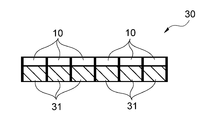
- FIG. 2 is a schematic view showing one embodiment of the light emitting structure of the present invention.
- the light diffusing member of the present invention includes rare earth compound particles and a matrix resin.
- the rare earth compound particles are arranged inside the light diffusing member and are used for causing light diffusion. Specifically, the rare earth compound particles are arranged in a state of being dispersed in the matrix resin, and are used for diffusing light incident on the light diffusing member.
- the diffusion of incident light generally includes forward diffusion and backward diffusion. With respect to diffusing light, rare earth compound particles are used for either or both forward and backward diffusion. In the following description, simply “spreading” includes both forward spreading and backward spreading.
- “light” means light including a wavelength region of visible light.
- a rare earth compound is generally a material having a high refractive index. Due to this, when the rare earth compound particles are dispersed and arranged in the matrix resin, light diffusion becomes suitable.
- the rare earth compound particles used in the present invention include particles containing a rare earth phosphate, a rare earth silicate, a rare earth oxide, and the like.
- the rare earth phosphate has a general formula represented by Ln (PO 3 ) 3 or LnPO 4 where Ln is a rare earth element.
- the rare earth silicate has a general formula represented by Ln 10 Si 6 O 27 , where Ln is a rare earth element.
- the rare-earth oxide has a rare-earth element of Ln and a general formula of Ln 2 O 3 .
- it is preferable to use rare earth phosphate particles as the rare earth compound particles from the viewpoint of enhancing light diffusivity.
- the general formula is LnPO 4 as the rare earth phosphate, light transmittance and light diffusivity are obtained. Is more preferable from the viewpoint of easily achieving both.
- rare earth compounds such as rare earth phosphates are generally materials having a high Abbe number
- the wavelength dependence of the refractive index is small compared to other high Abbe number materials such as zirconia. That is, when light including various wavelengths is incident, variation in the degree of refraction is small. As a result, diffused light with less color unevenness can be obtained by using the rare earth compound particles.
- the rare earth compound is an aggregate particle obtained by aggregating a plurality of primary particles made of the rare earth compound represented by the above general formula.
- Ln represents at least one element selected from the group consisting of Sc, Y, La, Ce, Pr, Nd, Sm, Eu, Gd, Tb, Dy, Ho, Er, Yb and Lu.
- it represents at least one element selected from Y, La, Eu, Gd, Dy, Yb and Lu.
- These rare earth compounds can be used alone or in combination of two or more.
- the primary particles described above may be a polycrystalline or single crystalline rare earth compound.
- the aggregation of the primary particles is caused by, for example, an intermolecular force, a chemical bond, a bond by a binder, or the like, and the aggregate particles are formed by aggregation of two or more primary particles.
- Such aggregate particles can be suitably produced, for example, by the method described below.
- the rare earth compound may be crystalline or amorphous. When the rare earth compound is crystalline, it is preferable in that the refractive index increases. When rare earth phosphate particles are produced as the rare earth compound by, for example, a method described later, crystalline rare earth phosphate is obtained.
- the rare earth compound particles preferably have a volume cumulative particle diameter D 50 at a cumulative volume of 50% by volume measured by a laser diffraction / scattering particle size distribution measurement method of 0.1 ⁇ m or more and 5 ⁇ m or less, and more preferably 0.2 ⁇ m or more and 2 ⁇ m or less. preferable.
- D50 volume cumulative particle diameter
- Particles having such a particle size can be suitably produced, for example, by a method described below.
- Cumulative volume particle diameter D 50 is measured by the following method.
- the rare earth compound particles are mixed with water, and subjected to ultrasonic dispersion treatment for one minute using a general ultrasonic bath.
- Cumulative volume particle diameter D 50 can be measured using a Beckman Coulter LS13 320 as a measuring device.
- the rare earth compound particles have a BET specific surface area of preferably from 1 m 2 / g to 50 m 2 / g, more preferably from 1 m 2 / g to 30 m 2 / g.
- the BET specific surface area can be measured, for example, by a BET one-point method using “Flowsorb 2300” manufactured by Shimadzu Corporation.
- the amount of the measurement sample is 0.3 g
- a mixed gas of nitrogen and helium is used as the adsorption gas
- the preliminary degassing condition is 120 ° C. for 10 minutes under atmospheric pressure.
- the light diffusion member of the present invention is configured to include rare earth compound particles and a matrix resin.
- a molded product such as a sheet, a film, a film, and a plate, a fluid such as a dispersion liquid (coating liquid), an ink, a paste, or a pellet (master batch) is formed.
- a fluid such as a dispersion liquid (coating liquid), an ink, a paste, or a pellet (master batch) is formed.
- the form of a sheet is advantageous because it can be easily applied to a structure having a light diffusing member.
- the light diffusing member may be used alone, or may be used as a molding for a sealing material in an LED light source in combination with another member such as a light source such as a light emitting diode (LED).
- LED light emitting diode
- thermoplastic resin a thermoplastic resin
- thermosetting resin an ionizing radiation-curable resin
- a two-component mixed-curing resin Resin can be used.
- thermoplastic resin it is preferable to use a thermoplastic resin as the matrix resin from the viewpoint that molding into a thick sheet is easy.
- thermosetting resin an ionizing radiation-curable resin, and a two-component mixed-curable resin as the matrix resin.
- thermoplastic resin examples include polyolefin resins such as polyethylene and polypropylene, polyester resins such as polyethylene terephthalate and polybutylene terephthalate, polycarbonate resins, polyacrylic acid such as polyacrylic acid or an ester thereof and polymethacrylic acid or an ester thereof. Resin, polyvinyl resin such as polystyrene and polyvinyl chloride, cellulosic resin such as triacetyl cellulose, urethane resin such as polyurethane and the like.
- thermosetting resin examples include a phenol resin, an epoxy resin, a melamine resin, a urea resin, an unsaturated polyester resin, an alkyd resin, a polyurethane resin, and a polyimide resin.
- ionizing radiation-curable resin examples include an acrylic resin, a urethane resin, a vinyl ester resin, a polyester alkyd resin, and the like. As these resins, not only polymers but also oligomers and monomers can be used.
- An example of the two-component curable resin is an epoxy resin.
- the light diffusing member of the present invention has a thickness T ( ⁇ m) of the light diffusing member and the addition of rare earth compound particles to the matrix resin from the viewpoint of securing high haze while preventing light emission unevenness such as a hot spot while providing light transmittance.
- the amount C (% by mass) is preferably in a specific range. That is, the product of the thickness T and the addition amount C (hereinafter, also referred to as T ⁇ C) is preferably 200 or more and 3000 or less.
- the addition amount C is 10% to 600% by mass. Is preferred.
- the thickness T is 50 ⁇ m or more and 3000 ⁇ m or less
- the addition amount C is preferably 0.1% by mass or more and 60% by mass or less. In any case, high haze can be ensured while providing light transmittance, and as a result, emission unevenness such as a hot spot can be suitably prevented.
- the thickness T is preferably 2 ⁇ m or more and 3000 ⁇ m or less.
- the thickness T of the light diffusing member has both light transmittance, haze, and ease of handling.
- a light diffusion structure composed of a light diffusion member disposed on a base material which will be described later, it refers to the thickness of the light diffusion member disposed on the base material.
- the thickness of the light diffusing member in the light emitting structure described below refers to the shortest length along the optical axis direction of the light emitting device. Therefore, even if the members have the same shape, the thickness of the light diffusing member may vary depending on the arrangement position with the light emitting device.
- the addition amount C of the rare earth compound particles to the matrix resin is more preferably 100% by mass or more and 400% by mass or less.
- the product of the thickness T and the addition amount C (T ⁇ C) is more preferably 500 or more and 3000 or less. With such a range, a high haze can be ensured while providing higher light transmittance, and as a result, uneven light emission such as a hot spot can be effectively prevented.
- the typical shape of the light diffusing member having a thickness T of 5 ⁇ m or more and less than 50 ⁇ m is a film-like or sheet-like thin film-like member.
- the product (T ⁇ C) of the thickness T and the addition amount C is more preferably 500 or more and 3000 or less.
- the typical shape of the light diffusion member having a thickness T of 50 ⁇ m or more and 3000 ⁇ m or less is a sheet-like or plate-like thick film-like member.
- the light diffusing member of the present invention may contain particles other than the rare earth compound particles.
- Other particles include inorganic oxide particles, inorganic sulfide particles, inorganic nitride particles, inorganic carbide particles, inorganic phosphate particles, and the like.
- the mixing amount of the other particles is preferably 50% by mass or less, more preferably 10% by mass or less, as a mixing amount with respect to the matrix resin.
- the rare earth compound particles used in the present invention can be subjected to a lipophilic treatment such as a coupling agent treatment or an organic acid treatment on the surface of the particles from the viewpoint of improving the dispersibility in the matrix resin.
- the coupling agent treatment for example, treatment using one or more coupling agents such as a silane coupling agent, a zirconium coupling agent, a titanium coupling agent, and an aluminum coupling agent is performed on the rare earth compound particles.
- a silane coupling agent when used, the silane compound formed on the surface of the rare earth compound particles by the treatment further has a lipophilic group. Is preferred. Examples of the lipophilic group include a linear or branched unsubstituted or substituted alkyl group having 1 to 20 carbon atoms.
- the substituent examples include an amino group, a vinyl group, an epoxy group, a styryl group, a methacryl group, an acryl group, a ureide group, a mercapto group, a sulfide group, and an isocyanate group.
- the amount of the silane compound is preferably 0.01% by mass or more and 200% by mass or less, particularly preferably 0.1% by mass or more and 100% by mass or less based on the mass of the rare earth compound particles.
- the organic acid treatment a treatment using an organic acid such as a carboxylic acid or a sulfonic acid can be performed on the rare earth compound particles.
- the carboxylic acid preferably has 1 to 20 carbon atoms and has a linear or branched unsubstituted or substituted alkyl group.
- Such carboxylic acids include, for example, butanoic, pentanoic, hexanoic, heptanoic, octanoic, nonanoic, decanoic, dodecanoic, tetradecanoic, pentadecanoic, hexadecanoic, heptadecanoic, cis-9- Octadecenoic acid, cis, cis-9,12-octadecadienoic acid and the like can be used.
- the light diffusing member preferably has a total light transmittance of 50% or more, more preferably 60% or more, and more preferably 70% or more. More preferred. Further, the haze of the light diffusing member is preferably 50% or more, more preferably 65% or more, further preferably 80% or more, from the viewpoint of preventing luminance unevenness such as a hot spot. preferable.
- the light diffusion member preferably has a total light transmittance of 50% or more and a haze of 50% or more, more preferably a total light transmittance of 60% or more and a haze of 65% or more. More preferably, the light transmittance is 70% or more and the haze is 80% or more.
- the light diffusing member has such physical properties, it is possible to effectively diffuse the direct light from the light source and make it difficult to generate uneven light emission such as a hot spot while expressing high luminance.
- the total light transmittance is 70% or more and the haze is 80% or more
- the light diffusing member is particularly suitable as a light diffusing member having high light transmittance and hardly causing uneven light emission such as a hot spot.
- the light diffusing member of the present invention can be used alone, or it can be disposed on a substrate as a coating layer to form the light diffusing structure shown in FIG.
- the light diffusion structure 20 shown in FIG. 1 has a laminated structure in which the light diffusion member 10 is disposed on a base 21.
- This light diffusion structure has a high haze value while maintaining the light transmittance of the base material.
- the thickness of the light-diffusing member in the light-diffusing structure can be changed according to the intended product. In particular, if the thickness T of the light-diffusing member and the addition amount C of the rare-earth compound particles fall within the above relational expressions, The effects of the present invention are sufficiently exhibited.
- the substrate used for the light diffusion structure is preferably a substrate made of a material having light transmittance.
- the light-transmitting material include polyolefin resins such as polyethylene and polypropylene, polyester resins such as polyethylene terephthalate (PET) and polybutylene terephthalate, polycarbonate resins, polyacrylic acid or esters thereof, and polymethacrylic acid or esters thereof.
- PET polyethylene terephthalate
- polycarbonate resins polyacrylic acid or esters thereof
- polymethacrylic acid or esters thereof and the like
- a polyacrylic resin such as polystyrene, a polyvinyl resin such as polystyrene and polyvinyl chloride, and a cellulosic resin such as triacetyl cellulose.
- the thickness of the base material is preferably 20 ⁇ m or more and 1000 ⁇ m or less from the viewpoint of durability as a light diffusion structure and workability during production.
- the light diffusing member of the present invention can exhibit high luminance while reducing light emission unevenness such as a hot spot caused by direct light from a light source.
- the light diffusing member of the present invention as it is or as a light diffusing structure, is, for example, a display, a lighting member, a window member, an illuminated member, a light guide plate member, a projector screen, an agricultural material such as a greenhouse, and the like. It is preferably used.
- the light diffusing member can also be used as a light emitting structure having a single light emitting device or optical device having a light source such as a light bulb, an LED element, a ⁇ LED element, or the like, or a plurality thereof.
- a light source such as a light bulb, an LED element, a ⁇ LED element, or the like
- the rate of emitting parallel transmitted light is higher than that of other light sources, so that light emission unevenness such as a hot spot easily occurs.
- the light diffusing member of the present invention as a sealing material for a light source such as an LED element and a ⁇ LED element in particular, it is possible to effectively prevent uneven light emission such as a hot spot and express high luminance. Can be.
- the light emitting structure 30 shown in FIG. 2 includes a plurality of light emitting devices 31 such as LED elements, and has a structure in which the light diffusing member 10 is arranged on a light emitting surface of the light emitting device 31.
- Examples of the light emitting structure having such a configuration include an image display device such as a display, a mobile device such as a liquid crystal TV, a personal computer, a tablet, and a smartphone, and a lighting device.
- the light diffusing member further includes a phosphor in addition to the rare earth compound particles and the matrix resin, from the viewpoint of achieving high luminance and enhancing emission of a specific color. It is preferred to mix the materials.
- a phosphor material for example, one or a combination of two or more of YAG (yttrium aluminum garnet), TAG (tellurium aluminum garnet), sialon, a sulfide-based material, and a silicate-based material can be used.
- the mixing amount of the phosphor material is preferably from 1% by mass to 100% by mass, more preferably from 10% by mass to 60% by mass, based on the matrix resin in the light diffusion member.
- the method for producing the light diffusing member is roughly classified into a step of preparing rare earth compound particles and a step of mixing and molding the particles and a matrix resin.
- rare earth compound particles prepare rare earth compound particles.
- a method for producing rare earth phosphate particles will be described by taking, as an example, the case where a rare earth phosphate is used as the rare earth compound.
- the rare earth phosphate was formed by mixing an aqueous solution containing one or more rare earth element sources with an aqueous solution containing a phosphate group to form a precipitate of one or more rare earth phosphates. Thereafter, the precipitate is dried by spray drying or the like, and then the dried product is fired to obtain rare earth phosphate particles.
- commercially available rare earth compound particles may be used as long as they satisfy the above-mentioned properties.
- the precipitation may be performed at a water temperature near room temperature or may be performed by heating.
- the heating temperature is preferably, for example, 50 ° C. or more and 400 ° C. or less in consideration of wet synthesis or hydrothermal synthesis.
- the heating temperature of the aqueous solution containing the rare earth element source is preferably from 50 ° C to 100 ° C, more preferably from 70 ° C to 95 ° C.
- the aqueous solution containing the rare earth element source has a rare earth element concentration in the aqueous solution of 0.01 mol / L to 1.5 mol / L, particularly 0.01 mol / L. It is preferable to use a compound having a concentration of at least 1 mol / L, particularly at least 0.01 mol / L and at most 0.5 mol / L.
- the rare earth element is preferably in a trivalent ion state, or in a complex ion state in which a ligand is coordinated to the trivalent ion.
- a rare earth oxide for example, Ln 2 O 3 or the like
- a rare earth oxide for example, Ln 2 O 3 or the like
- the total concentration of the phosphoric acid species in the aqueous solution is adjusted to 0.01 mol / L or more and 3 mol / L or less, particularly 0.01 mol / L or more and 1 mol / L or less. In particular, it is preferable to be 0.01 mol / L or more and 0.5 mol / L or less.
- an alkaline species may be added.
- the alkali species for example, basic compounds such as ammonia, ammonium hydrogen carbonate, ammonium carbonate, sodium hydrogen carbonate, sodium carbonate, ethylamine, propylamine, sodium hydroxide, potassium hydroxide and the like can be used.
- the aqueous solution containing the rare earth element source and the aqueous solution containing the phosphate group are mixed such that the molar ratio of phosphate ions to rare earth element ions is 0.5 or more, 10 or less, especially 1 or more and 10 or less, especially 1 or more and 5 or less. Is preferred from the viewpoint that a precipitation product can be efficiently obtained.
- the rare earth phosphate particles are obtained as described above, they are subjected to solid-liquid separation by a solid-liquid separation method such as filtration or decantation, and then washed once or a plurality of times. Washing with water is preferably performed until the conductivity of the supernatant liquid becomes, for example, 2000 ⁇ S / cm or less.
- the rare earth phosphate precipitate can be fired in an oxygen-containing atmosphere such as the air.
- the firing temperature is preferably from 80 ° C to 1500 ° C, more preferably from 400 ° C to 1300 ° C.
- the firing time is preferably from 1 hour to 20 hours, more preferably from 1 hour to 10 hours, provided that the firing temperature is within the above range.
- the rare earth compound particles obtained in the above-described steps, the matrix resin, and, if necessary, the phosphor material and other components are mixed to form a desired shape.
- the particle size of the rare earth compound particles used in this step may be adjusted using a pulverizing means such as a paint shaker.
- the molding performed in this step is performed by, for example, adding a rare-earth compound particle to a molten matrix resin and kneading the mixture, followed by an inflation method, a T-die method, a calendering method, etc. (hereinafter, this molding method is referred to as “kneading”). Molding ").
- the light diffusing member manufactured by such a method may be used as it is, or alternatively, a light diffusing member may be formed by arranging a molded light diffusing member on a substrate, or a light diffusing member. Can be combined with a light emitting device such as an LED element to produce a light emitting structure. In any case, the effects of the present invention are sufficiently exhibited.
- the light diffusing member, the light diffusing structure and the light emitting structure may be used in combination.
- a liquid mixture containing rare earth compound particles and a matrix resin is disposed on the surface of a substrate or a light emitting device, and a light diffusion member can be directly molded on the substrate or the light emitting device (hereinafter, referred to as a light diffusing member).
- This molding method is also referred to as “direct molding”). In this way, it is possible to manufacture a light diffusing structure in which the light diffusing member is disposed on the base material, and a light emitting structure including the light diffusing member on a light emitting device such as an LED element.
- This method is, for example, to prepare a coating solution by mixing a rare earth compound particles, a matrix resin and an organic solvent, screen printing, gravure printing, offset printing, various printing methods such as flexo method, bar and roller and A method of applying or spraying on a substrate or a surface of a light emitting device by using a spray gun or the like, followed by drying.
- the light diffusion member when the light diffusion member is manufactured by kneading, it is preferable that the light diffusion member is formed so that the thickness T is 50 ⁇ m or more and 3000 ⁇ m or less. From the same viewpoint, when the light diffusing member is manufactured by direct molding, it is preferable to mold the light diffusing member so that the thickness T is 2 ⁇ m or more and less than 50 ⁇ m.
- a light diffusing member was manufactured using yttrium phosphate particles as rare earth compound particles and an acrylic resin as a matrix resin.
- the method for producing rare earth phosphate particles composed of yttrium phosphate is as follows. That is, 600 g of water was weighed into the glass container 1, 61.7 g of 60% by mass nitric acid (manufactured by Wako Pure Chemical Industries) and 18.8 g of Y 2 O 3 (manufactured by Nippon Yttrium) were added, and the mixture was heated to 80 ° C. And dissolved. In another glass container 2, 600 g of water was weighed, and 18.8 g of 85% by mass phosphoric acid was added. Next, the contents of the glass container 2 were added into the glass container 1 and aged for 1 hour to obtain a precipitate.
- nitric acid manufactured by Wako Pure Chemical Industries
- Y 2 O 3 manufactured by Nippon Yttrium
- the obtained precipitate was subjected to decantation washing, and washing was performed until the conductivity of the supernatant became 100 ⁇ S / cm or less. After washing, solid-liquid separation was performed by vacuum filtration, and the separated solid was dried in the air at 120 ° C. for 5 hours, and then calcined in the air at 900 ° C. for 3 hours to obtain yttrium phosphate particles.
- the D 50 of the particles was 1 ⁇ m, and the specific surface area was 2 m 2 / g.
- the obtained yttrium phosphate particles and an acrylic resin (manufactured by DIC Corporation, product name: A-165) were blended so that the addition amount C of the yttrium phosphate particles to the matrix resin was 100% by mass,
- the mixture was diluted with 2-butanone (MEK solvent) and mixed with a paint shaker for 60 minutes to prepare a coating liquid.
- this coating liquid is applied to a PET substrate (thickness: 100 ⁇ m) using a bar coater so that the coating thickness becomes 5 ⁇ m, and dried at 80 ° C. for 5 minutes. Was obtained.
- Examples 2 to 4 and Comparative Examples 1 to 3 The production was performed in the same manner as in Example 1 except that the amount C of the particles added to the matrix resin and the thickness T of the light diffusing member were changed as shown in Table 1 below.
- Example 5 After pre-mixing the particles of yttrium phosphate obtained in Example 1 and a polycarbonate resin (manufactured by Sumika Polycarbonate, 301-22) so that the added amount C of the particles to the matrix resin is 5% by mass. The mixture was extruded to form a sheet-like light diffusing member having a length of 100 mm ⁇ width of 100 mm and a thickness T of 75 ⁇ m.
- a polycarbonate resin manufactured by Sumika Polycarbonate, 301-22
- Example 6 to 18 and Comparative Examples 4 to 6 Except that the amount C of the particles added to the matrix resin and the thickness T of the light diffusing member were changed as shown in Table 1 below, it was manufactured in the same manner as in Example 5.
- Example 19 For yttrium phosphate particles, its particle size D 50 of 0.3 [mu] m, a specific surface area was prepared so as to be 8m 2 / g. It was manufactured in the same manner as in Example 1 except that the amount C of the particles added to the matrix resin and the thickness T of the light diffusing member were changed as shown in Table 1 below.
- yttrium oxide particles is a rare earth oxide (Nippon Yttrium Co.: D 50: 0.3 [mu] m, a specific surface area: 10m 2 / g) was used.
- the production was performed in the same manner as in Example 1 except that the amount C of the particles added to the matrix resin and the thickness T of the light diffusing member were changed as shown in Table 1 below.
- Light transmission and haze It was measured using a haze meter (NDH2000 manufactured by Nippon Denshoku Industries Co., Ltd.). Light transmittance was evaluated as total light transmittance (%). The overall evaluation of light transmittance and haze was evaluated according to the following criteria. The results are shown in Table 1 below.
- [Hot spot presence] AS-LC01 manufactured by Asahi Denki Co., Ltd. was used as an LED light source.
- the light-diffusing members or light-diffusing structures of Examples and Comparative Examples were arranged at a position 1 cm above the LED light source, and the light emission of the LED light source was set to a high luminance mode to check for the presence or absence of a hot spot.
- the evaluation of the presence / absence of a hot spot was made when the outline (hot spot) of the LED light source was not clearly seen when the LED light source was visually confirmed through the light diffusion member or the light diffusion structure. Those that were clearly visible were marked "x".
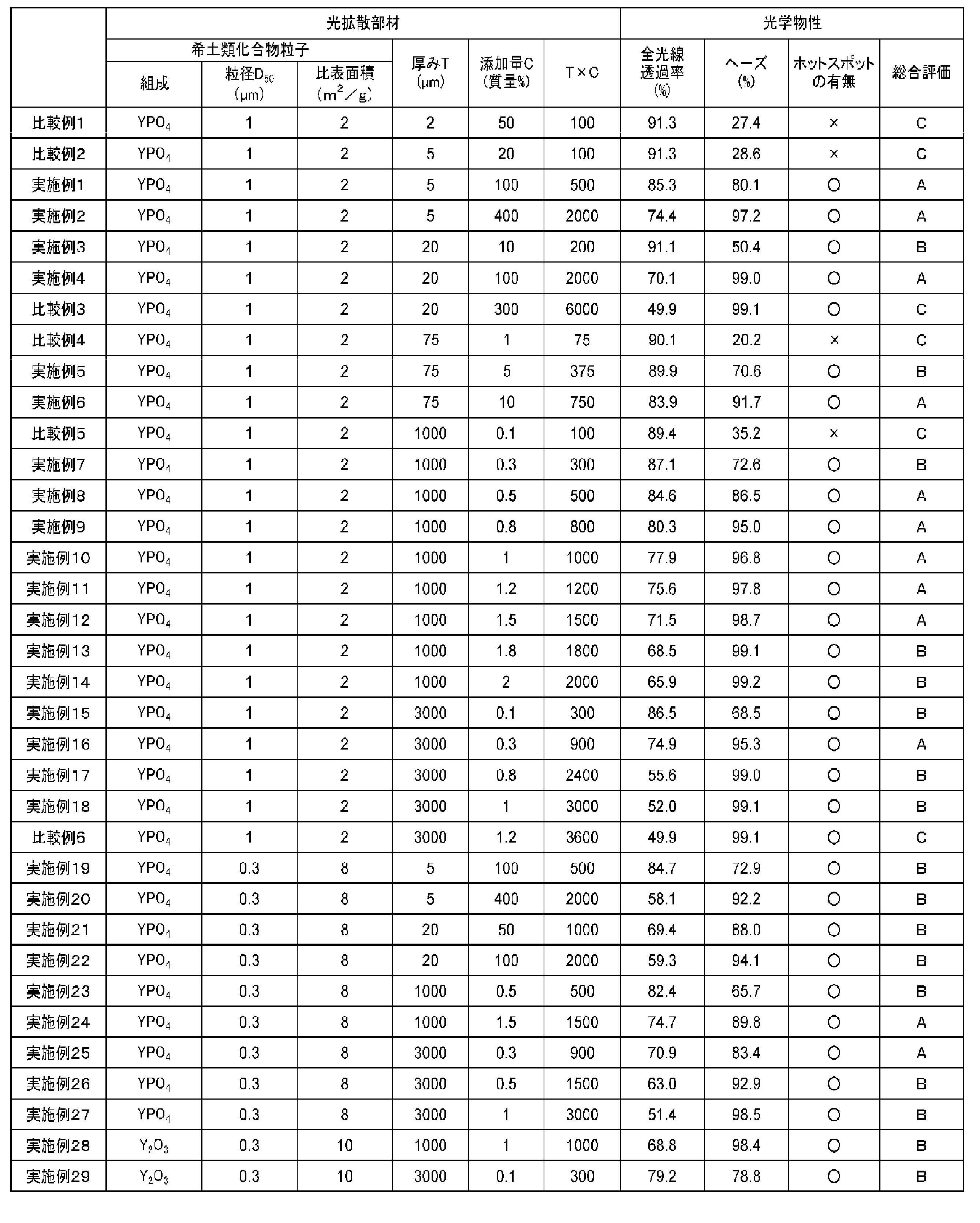
- Table 1 The evaluation results are shown in Table 1 below.
- the light-diffusion member which has the light transmittance and has few light emission unevenness, such as a hot spot, a light-diffusion structure and a light-emitting structure using this are provided.
Landscapes
- Physics & Mathematics (AREA)
- General Physics & Mathematics (AREA)
- Optics & Photonics (AREA)
- Chemical & Material Sciences (AREA)
- Engineering & Computer Science (AREA)
- General Engineering & Computer Science (AREA)
- Crystallography & Structural Chemistry (AREA)
- Dispersion Chemistry (AREA)
- Optical Elements Other Than Lenses (AREA)
- Devices For Indicating Variable Information By Combining Individual Elements (AREA)
- Overhead Projectors And Projection Screens (AREA)
- Led Device Packages (AREA)
- Luminescent Compositions (AREA)
Abstract
Description
前記光拡散部材の厚みをT(μm)とし、前記マトリクス樹脂に対する前記粒子の添加量をC(質量%)としたとき、
厚みTと添加量Cとの積が200以上3000以下であり、
厚みTが2μm以上50μm未満のとき、添加量Cが10質量%以上600質量%以下であり、
厚みTが50μm以上3000μm以下のとき、添加量Cが0.1質量%以上60質量%以下である、光拡散部材を提供するものである。
希土類化合物粒子であるリン酸イットリウムの粒子と、マトリクス樹脂であるアクリル樹脂とを用いて、光拡散部材を製造した。
マトリクス樹脂に対する粒子の添加量C、及び光拡散部材の厚みTを以下の表1に示すとおりに変更したほかは、実施例1と同様に製造した。
実施例1で得られたリン酸イットリウムの粒子と、ポリカーボネート樹脂(住化ポリカーボネート社製、301-22)とを、マトリクス樹脂に対する粒子の添加量Cが5質量%となるように予備混合した後、該混合物を押し出し成形して、縦100mm×横100mm、厚みTが75μmのシート状の光拡散部材を作製した。
マトリクス樹脂に対する粒子の添加量C、及び光拡散部材の厚みTを以下の表1に示すとおりに変更したほかは、実施例5と同様に製造した。
リン酸イットリウム粒子について、その粒径D50が0.3μmに、比表面積が8m2/gになるよう製造した。マトリクス樹脂に対する粒子の添加量C、及び光拡散部材の厚みTを以下の表1に示すとおりに変更したほかは、実施例1と同様に製造した。
リン酸イットリウムに代えて、希土類酸化物である酸化イットリウム粒子(日本イットリウム社製:D50:0.3μm、比表面積:10m2/g)を用いた。マトリクス樹脂に対する粒子の添加量C、及び光拡散部材の厚みTを以下の表1に示すとおりに変更したほかは、実施例1と同様に製造した。
ヘーズメーター(日本電色工業株式会社製、NDH2000)を用いて測定した。光透過性は全光線透過率(%)として評価した。また、光透過性及びヘーズの総合評価を以下の基準で評価した。これらの結果を以下の表1に示す。
LED光源として朝日電器社製AS-LC01を用いた。LED光源上1cmの位置に、実施例及び比較例の光拡散部材又は光拡散構造体を配置し、LED光源の発光を高輝度モードにしてホットスポットの有無を確認した。ホットスポットの有無の評価は、LED光源を光拡散部材又は光拡散構造体越しに目視確認した際に、LED光源の輪郭(ホットスポット)がはっきり見えなかったものを「○」とし、該輪郭がはっきり見えたものを「×」とした。評価結果を以下の表1に示す。
<総合評価>
A:全光線透過率が70%以上であり、ヘーズが80%以上であり、且つホットスポットがはっきり見えない。
B:全光線透過率が50%以上であり、且つホットスポットがはっきり見えない。
C:全光線透過率が50%未満であるか、又はホットスポットがはっきり見える。
Claims (9)
- 希土類化合物粒子とマトリクス樹脂とを含んでなる光拡散部材であって、
前記光拡散部材の厚みをT(μm)とし、前記マトリクス樹脂に対する前記粒子の添加量をC(質量%)としたとき、
厚みTと添加量Cとの積が200以上3000以下であり、
厚みTが2μm以上50μm未満のとき、添加量Cが10質量%以上600質量%以下であり、
厚みTが50μm以上3000μm以下のとき、添加量Cが0.1質量%以上60質量%以下である、光拡散部材。 - 前記粒子は、レーザー回折散乱式粒度分布測定法による累積体積50容量%における体積累積粒径D50が、0.1μm以上5μm以下である、請求項1に記載の光拡散部材。
- 全光線透過率が50%以上であり、且つヘーズが50%以上である、請求項1又は2に記載の光拡散部材。
- 前記粒子は、希土類リン酸塩粒子である請求項1ないし3のいずれか一項に記載の光拡散部材。
- 前記粒子は、Ln(PO3)3又はLnPO4で表されてなり、式中のLnは、Sc、Y、La、Ce、Pr、Nd、Sm、Eu、Gd、Tb、Dy、Ho、Er、Yb及びLuからなる群より選ばれる少なくとも一種の元素からなる請求項4に記載の光拡散部材。
- 前記粒子のBET比表面積が、1m2/g以上50m2/g以下である、請求項1ないし5のいずれか一項に記載の光拡散部材。
- 請求項1ないし6のいずれか一項に記載の光拡散部材が基材上に配されてなる光拡散構造体。
- 請求項1ないし6のいずれか一項に記載の光拡散部材及び発光デバイスを備えてなる発光構造体。
- 前記発光デバイスは、発光ダイオードである請求項8に記載の発光構造体。
Priority Applications (2)
| Application Number | Priority Date | Filing Date | Title |
|---|---|---|---|
| JP2020536397A JP6975863B2 (ja) | 2018-08-07 | 2019-07-10 | 光拡散部材、並びにこれを用いた光拡散構造体及び発光構造体 |
| KR1020217001917A KR102788996B1 (ko) | 2018-08-07 | 2019-07-10 | 광 확산 부재, 그리고 이것을 사용한 광 확산 구조체 및 발광 구조체 |
Applications Claiming Priority (2)
| Application Number | Priority Date | Filing Date | Title |
|---|---|---|---|
| JP2018148248 | 2018-08-07 | ||
| JP2018-148248 | 2018-08-07 |
Publications (1)
| Publication Number | Publication Date |
|---|---|
| WO2020031598A1 true WO2020031598A1 (ja) | 2020-02-13 |
Family
ID=69415503
Family Applications (1)
| Application Number | Title | Priority Date | Filing Date |
|---|---|---|---|
| PCT/JP2019/027280 Ceased WO2020031598A1 (ja) | 2018-08-07 | 2019-07-10 | 光拡散部材、並びにこれを用いた光拡散構造体及び発光構造体 |
Country Status (4)
| Country | Link |
|---|---|
| JP (1) | JP6975863B2 (ja) |
| KR (1) | KR102788996B1 (ja) |
| TW (1) | TWI847990B (ja) |
| WO (1) | WO2020031598A1 (ja) |
Cited By (3)
| Publication number | Priority date | Publication date | Assignee | Title |
|---|---|---|---|---|
| JP2022177155A (ja) * | 2020-10-20 | 2022-11-30 | 大日本印刷株式会社 | 面発光装置、表示装置、面発光装置用封止部材シートおよび面発光装置の製造方法 |
| JP2023067740A (ja) * | 2021-11-01 | 2023-05-16 | 日亜化学工業株式会社 | 発光装置およびそれに用いる拡散部材 |
| JP2024039071A (ja) * | 2021-11-01 | 2024-03-21 | 日亜化学工業株式会社 | 発光装置およびそれに用いる拡散部材 |
Citations (9)
| Publication number | Priority date | Publication date | Assignee | Title |
|---|---|---|---|---|
| JP2000208815A (ja) * | 1996-07-29 | 2000-07-28 | Nichia Chem Ind Ltd | 発光ダイオ―ド |
| JP2003177236A (ja) * | 2001-12-12 | 2003-06-27 | Nitto Denko Corp | 干渉型半透過反射板、およびそれを用いた干渉型半透過反射板付き偏光板、半透過反射液晶基板、ならびに半透過反射液晶表示装置 |
| JP2004029648A (ja) * | 2002-06-28 | 2004-01-29 | Takiron Co Ltd | 光拡散シート |
| JP2005024942A (ja) * | 2003-07-03 | 2005-01-27 | Kimoto & Co Ltd | 透過型スクリーン |
| JP2008003625A (ja) * | 2007-08-10 | 2008-01-10 | Dainippon Printing Co Ltd | 平面膜状拡散層付偏光板および当該偏光板を用いた液晶表示装置 |
| JP2016138309A (ja) * | 2015-01-27 | 2016-08-04 | 日本イットリウム株式会社 | 溶射用粉末及び溶射材料 |
| CN106896567A (zh) * | 2017-03-17 | 2017-06-27 | 京东方科技集团股份有限公司 | 一种偏光片及显示装置 |
| WO2017130868A1 (ja) * | 2016-01-25 | 2017-08-03 | 旭硝子株式会社 | 光拡散板 |
| WO2018025800A1 (ja) * | 2016-08-02 | 2018-02-08 | 三井金属鉱業株式会社 | 希土類リン酸塩粒子、それを用いた散乱性向上方法 |
Family Cites Families (2)
| Publication number | Priority date | Publication date | Assignee | Title |
|---|---|---|---|---|
| CN1049881C (zh) * | 1995-12-15 | 2000-03-01 | 国家建筑材料工业局人工晶体研究所 | 一种透明多晶尖晶石的制备方法 |
| DE102008041055A1 (de) * | 2008-08-06 | 2010-02-18 | Carl Zeiss Smt Ag | Transmittierendes optisches Element aus Magnesium-Aluminium-Spinell |
-
2019
- 2019-07-10 KR KR1020217001917A patent/KR102788996B1/ko active Active
- 2019-07-10 JP JP2020536397A patent/JP6975863B2/ja active Active
- 2019-07-10 WO PCT/JP2019/027280 patent/WO2020031598A1/ja not_active Ceased
- 2019-07-17 TW TW108125259A patent/TWI847990B/zh active
Patent Citations (9)
| Publication number | Priority date | Publication date | Assignee | Title |
|---|---|---|---|---|
| JP2000208815A (ja) * | 1996-07-29 | 2000-07-28 | Nichia Chem Ind Ltd | 発光ダイオ―ド |
| JP2003177236A (ja) * | 2001-12-12 | 2003-06-27 | Nitto Denko Corp | 干渉型半透過反射板、およびそれを用いた干渉型半透過反射板付き偏光板、半透過反射液晶基板、ならびに半透過反射液晶表示装置 |
| JP2004029648A (ja) * | 2002-06-28 | 2004-01-29 | Takiron Co Ltd | 光拡散シート |
| JP2005024942A (ja) * | 2003-07-03 | 2005-01-27 | Kimoto & Co Ltd | 透過型スクリーン |
| JP2008003625A (ja) * | 2007-08-10 | 2008-01-10 | Dainippon Printing Co Ltd | 平面膜状拡散層付偏光板および当該偏光板を用いた液晶表示装置 |
| JP2016138309A (ja) * | 2015-01-27 | 2016-08-04 | 日本イットリウム株式会社 | 溶射用粉末及び溶射材料 |
| WO2017130868A1 (ja) * | 2016-01-25 | 2017-08-03 | 旭硝子株式会社 | 光拡散板 |
| WO2018025800A1 (ja) * | 2016-08-02 | 2018-02-08 | 三井金属鉱業株式会社 | 希土類リン酸塩粒子、それを用いた散乱性向上方法 |
| CN106896567A (zh) * | 2017-03-17 | 2017-06-27 | 京东方科技集团股份有限公司 | 一种偏光片及显示装置 |
Cited By (7)
| Publication number | Priority date | Publication date | Assignee | Title |
|---|---|---|---|---|
| JP2022177155A (ja) * | 2020-10-20 | 2022-11-30 | 大日本印刷株式会社 | 面発光装置、表示装置、面発光装置用封止部材シートおよび面発光装置の製造方法 |
| JP7327610B2 (ja) | 2020-10-20 | 2023-08-16 | 大日本印刷株式会社 | 面発光装置、表示装置、面発光装置用封止部材シートおよび面発光装置の製造方法 |
| JP2023067740A (ja) * | 2021-11-01 | 2023-05-16 | 日亜化学工業株式会社 | 発光装置およびそれに用いる拡散部材 |
| JP7436893B2 (ja) | 2021-11-01 | 2024-02-22 | 日亜化学工業株式会社 | 発光装置およびそれに用いる拡散部材 |
| JP2024039071A (ja) * | 2021-11-01 | 2024-03-21 | 日亜化学工業株式会社 | 発光装置およびそれに用いる拡散部材 |
| JP7633574B2 (ja) | 2021-11-01 | 2025-02-20 | 日亜化学工業株式会社 | 発光装置およびそれに用いる拡散部材 |
| US12457832B2 (en) | 2021-11-01 | 2025-10-28 | Nichia Corporation | Light emitting device and diffusion member used therein |
Also Published As
| Publication number | Publication date |
|---|---|
| JP6975863B2 (ja) | 2021-12-01 |
| JPWO2020031598A1 (ja) | 2021-03-18 |
| TW202017857A (zh) | 2020-05-16 |
| TWI847990B (zh) | 2024-07-11 |
| KR20210040362A (ko) | 2021-04-13 |
| KR102788996B1 (ko) | 2025-03-28 |
Similar Documents
| Publication | Publication Date | Title |
|---|---|---|
| KR101775260B1 (ko) | 색도 좌표와 색 영역 조절이 가능한 형광 필름 | |
| KR101686210B1 (ko) | 황색 형광체를 포함하는 확산시트 | |
| CN107924975A (zh) | 波长转换部件、荧光体片、白色光源装置及显示装置 | |
| CN107110446B (zh) | 背光单元和包括其的显示装置 | |
| EP3532893B1 (en) | Display device comprising a backlight unit | |
| WO2015037733A1 (ja) | 波長変換シート及びバックライトユニット | |
| CN104459845A (zh) | 一种量子点光扩散膜 | |
| JP6975863B2 (ja) | 光拡散部材、並びにこれを用いた光拡散構造体及び発光構造体 | |
| WO2015081692A1 (zh) | 一种导光板、背光源及液晶显示装置 | |
| Lai et al. | High-efficiency robust free-standing composited phosphor films with 2D and 3D nanostructures for high-power remote white LEDs | |
| CN203275836U (zh) | 显示装置 | |
| TWI782156B (zh) | 粒子混合體、使用其之光散射性提升方法、以及含有其之光散射構件及光學裝置 | |
| JPWO2019181368A1 (ja) | 光散乱体、光散乱体形成用組成物、シート状積層体、投影スクリーン、光拡散シート及び光エンハンサー内蔵照明装置 | |
| CN101747681B (zh) | 油墨及其制备方法和制备膜材的方法 | |
| KR20160094885A (ko) | 색변환 필름 및 이를 포함하는 백라이트 유닛 | |
| CN111406100B (zh) | 包覆荧光体、其制造方法、以及荧光体片和发光装置 | |
| JP7050814B2 (ja) | 希土類リン酸塩粒子、それを用いた光散乱性向上方法、並びにそれを含む光散乱部材及び光学デバイス | |
| CN113823727A (zh) | 一种具备高防潮特性的荧光粉薄膜及其应用 | |
| CN111417699A (zh) | 绿色荧光体、荧光体片和发光装置 | |
| CN107022236A (zh) | 一种导光油墨及其制备方法 | |
| JP2016196121A (ja) | 全光透過性を有した白色発光蓄光シート | |
| JP2006267892A (ja) | 光学素子及びこれを用いた偏光面光源並びにこれを用いた表示装置 |
Legal Events
| Date | Code | Title | Description |
|---|---|---|---|
| 121 | Ep: the epo has been informed by wipo that ep was designated in this application |
Ref document number: 19847573 Country of ref document: EP Kind code of ref document: A1 |
|
| ENP | Entry into the national phase |
Ref document number: 2020536397 Country of ref document: JP Kind code of ref document: A |
|
| ENP | Entry into the national phase |
Ref document number: 20217001917 Country of ref document: KR Kind code of ref document: A |
|
| NENP | Non-entry into the national phase |
Ref country code: DE |
|
| 122 | Ep: pct application non-entry in european phase |
Ref document number: 19847573 Country of ref document: EP Kind code of ref document: A1 |