WO2020031582A1 - 加工装置および切削加工方法 - Google Patents
加工装置および切削加工方法 Download PDFInfo
- Publication number
- WO2020031582A1 WO2020031582A1 PCT/JP2019/026969 JP2019026969W WO2020031582A1 WO 2020031582 A1 WO2020031582 A1 WO 2020031582A1 JP 2019026969 W JP2019026969 W JP 2019026969W WO 2020031582 A1 WO2020031582 A1 WO 2020031582A1
- Authority
- WO
- WIPO (PCT)
- Prior art keywords
- rotation
- acceleration
- deceleration
- spindle
- speed
- Prior art date
- Legal status (The legal status is an assumption and is not a legal conclusion. Google has not performed a legal analysis and makes no representation as to the accuracy of the status listed.)
- Ceased
Links
Images

Classifications
-
- B—PERFORMING OPERATIONS; TRANSPORTING
- B23—MACHINE TOOLS; METAL-WORKING NOT OTHERWISE PROVIDED FOR
- B23B—TURNING; BORING
- B23B7/00—Automatic or semi-automatic turning-machines with a single working-spindle, e.g. controlled by cams; Equipment therefor; Features common to automatic and semi-automatic turning-machines with one or more working-spindles
-
- B—PERFORMING OPERATIONS; TRANSPORTING
- B23—MACHINE TOOLS; METAL-WORKING NOT OTHERWISE PROVIDED FOR
- B23B—TURNING; BORING
- B23B1/00—Methods for turning or working essentially requiring the use of turning-machines; Use of auxiliary equipment in connection with such methods
-
- B—PERFORMING OPERATIONS; TRANSPORTING
- B23—MACHINE TOOLS; METAL-WORKING NOT OTHERWISE PROVIDED FOR
- B23B—TURNING; BORING
- B23B25/00—Accessories or auxiliary equipment for turning-machines
- B23B25/06—Measuring, gauging, or adjusting equipment on turning-machines for setting-on, feeding, controlling, or monitoring the cutting tools or work
-
- B—PERFORMING OPERATIONS; TRANSPORTING
- B23—MACHINE TOOLS; METAL-WORKING NOT OTHERWISE PROVIDED FOR
- B23Q—DETAILS, COMPONENTS, OR ACCESSORIES FOR MACHINE TOOLS, e.g. ARRANGEMENTS FOR COPYING OR CONTROLLING; MACHINE TOOLS IN GENERAL CHARACTERISED BY THE CONSTRUCTION OF PARTICULAR DETAILS OR COMPONENTS; COMBINATIONS OR ASSOCIATIONS OF METAL-WORKING MACHINES, NOT DIRECTED TO A PARTICULAR RESULT
- B23Q15/00—Automatic control or regulation of feed movement, cutting velocity or position of tool or work
- B23Q15/007—Automatic control or regulation of feed movement, cutting velocity or position of tool or work while the tool acts upon the workpiece
- B23Q15/12—Adaptive control, i.e. adjusting itself to have a performance which is optimum according to a preassigned criterion
-
- B—PERFORMING OPERATIONS; TRANSPORTING
- B23—MACHINE TOOLS; METAL-WORKING NOT OTHERWISE PROVIDED FOR
- B23B—TURNING; BORING
- B23B2250/00—Compensating adverse effects during turning, boring or drilling
- B23B2250/16—Damping of vibrations
-
- G—PHYSICS
- G05—CONTROLLING; REGULATING
- G05B—CONTROL OR REGULATING SYSTEMS IN GENERAL; FUNCTIONAL ELEMENTS OF SUCH SYSTEMS; MONITORING OR TESTING ARRANGEMENTS FOR SUCH SYSTEMS OR ELEMENTS
- G05B2219/00—Program-control systems
- G05B2219/30—Nc systems
- G05B2219/41—Servomotor, servo controller till figures
- G05B2219/41256—Chattering control
Definitions
- the present disclosure relates to a processing device and a cutting method.
- Reproduction chatter vibration is the vibration that occurred when cutting one rotation before (one cutting edge before with a multi-blade tool) remains as undulation of the machined surface, and the vibration is reproduced as a change in the cut thickness in the current cutting. Self-excited vibration. For this reason, a closed loop is formed in which the cutting force fluctuates and vibration is generated again. When the loop gain is increased, the vibration grows and large chatter vibration occurs. The “regenerated chatter vibration” not only deteriorates the finishing accuracy of the machined surface, but can also be a factor of the loss of the cutting tool.
- Patent Literature 1 discloses a method of suppressing "chatter vibration" by changing the rotation speed of a main spindle in a short cycle in a state where a feed rate of a cutting tool is kept constant when turning a work material. I do.
- the main shaft rotation speed When the main shaft rotation speed is periodically changed, the ratio between the current speed and the speed one rotation before becomes close to 1 before and after the change of the rotation speed is switched.
- the main shaft rotation speed may be periodically fluctuated by a triangular wave fluctuation pattern, but as a result of analyzing the fluctuation pattern of the triangular wave, the rotation speed becomes a maximum value.
- regenerative chatter Before and after, we found that regenerative chatter could occur.
- the present inventor has repeatedly studied a periodic fluctuation pattern of the spindle rotation speed, and has come to specify a fluctuation pattern that effectively suppresses the regenerative chatter vibration.
- the present disclosure has been made in view of such circumstances, and a purpose thereof is to provide a cutting technique that effectively suppresses regenerative chatter vibration.
- a processing apparatus includes a rotation mechanism that rotates a main spindle to which a cutting tool or a work material is attached, a rotation control unit that controls rotation of the main spindle by the rotation mechanism, A feed mechanism for relatively moving the cutting tool with respect to the work material.
- a rotation control unit configured to accelerate the rotation of the main spindle so that a speed variation ratio, which is a ratio between the current cutting speed at the same rotation position and the cutting speed one rotation before, is equal to or greater than a first value greater than 1;
- the deceleration control for decelerating the rotation of the main shaft so that the speed fluctuation ratio becomes equal to or less than a second value smaller than 1 is alternately executed.
- ⁇ Another embodiment of the present disclosure relates to a cutting method.
- This method includes a rotation control step of controlling the rotation of a spindle to which a cutting tool or a work material is attached, and moving the cutting tool relative to the work material during rotation of the spindle, thereby performing machining by the cutting tool.
- a processing step of performing The rotation control step is an acceleration control for accelerating the rotation of the spindle so that a speed variation ratio, which is a ratio between the current cutting speed at the same rotation position and the cutting speed one rotation before, is equal to or greater than a first value greater than 1.
- the deceleration control for reducing the rotation of the main shaft so that the speed fluctuation ratio becomes equal to or less than a second value smaller than 1 is alternately executed.
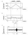
- (A)-(c) is a figure which shows the simulation result at the time of controlling a main shaft rotation speed with the fluctuation pattern of a triangular wave.
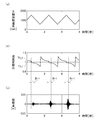
- (A)-(c) is a figure which shows the simulation result at the time of controlling a main shaft rotation speed with the fluctuation pattern of a triangular wave.
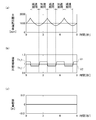
- (A)-(c) is a figure which shows the simulation result at the time of controlling a spindle rotation speed with the fluctuation pattern of embodiment.
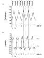
- (A)-(b) is a figure which shows the simulation result at the time of controlling a main shaft rotation speed with the variation pattern of a modification.
- FIG. 1 shows a schematic configuration of a processing apparatus 1 according to the embodiment.
- the processing device 1 is a cutting device that performs turning by bringing the cutting edge of a cutting tool 10 into contact with a work material 6.
- the processing apparatus 1 includes a headstock 2 and a tailstock 3 that rotatably support a work material 6 on a bed 5, and a tool rest 4 that supports a cutting tool 10.
- the rotation mechanism 8 is provided inside the headstock 2 and rotates the spindle 2a to which the work material 6 is attached.
- the feed mechanism 7 is provided on the bed 5 and moves the cutting tool 10 relative to the workpiece 6.
- the feed tool 7 moves the tool rest 4 in the X-axis, Y-axis, and Z-axis directions, thereby moving the cutting tool 10 relative to the workpiece 6.
- the X-axis direction is a cutting direction that is horizontal and orthogonal to the axial direction of the work material 6
- the Y-axis direction is a cutting direction that is a vertical direction
- the Z-axis direction is the axial direction of the work material 6.
- the feed directions are parallel.
- the control unit 20 controls the rotation of the spindle 2a by the rotation mechanism 8, and the cutting tool 10 is brought into contact with the workpiece 6 by the feed mechanism 7 during the rotation of the spindle 2a.
- a movement control unit 22 for performing the following.
- the processing device 1 may be an NC machine tool.
- the rotation mechanism 8 and the feed mechanism 7 each include a drive unit such as a motor, and the rotation control unit 21 and the movement control unit 22 adjust power supplied to the drive unit, respectively, and The respective behaviors of the mechanism 7 are controlled.
- the work material 6 is attached to the main shaft 2a and rotated by the rotating mechanism 8, but in another example, the cutting tool 10 is attached to the main shaft 2a and rotated by the rotating mechanism 8. You may be made to. Further, the feed mechanism 7 may move the cutting tool 10 relatively to the work material 6 and may have a mechanism for moving at least one of the cutting tool 10 and the work material 6.
- FIG. 2A shows a fluctuation pattern of the triangular wave of the spindle rotation speed.
- the cycle of this fluctuation pattern is 2 seconds, and the speed is changed at a constant acceleration and a constant deceleration within a range where the minimum value is 1400 rpm and the maximum value is 2600 rpm.
- the acceleration period from the minimum value to the maximum value is equal to the deceleration period from the maximum value to the minimum value, each being 1 second.
- FIG. 2B shows a transition pattern of the speed fluctuation ratio.
- the speed fluctuation ratio is derived by the following equation.
- Speed fluctuation ratio (current cutting speed / cutting speed before one rotation)
- the speed fluctuation ratio gradually decreases while the speed fluctuation ratio exceeds 1 during the acceleration period of the main shaft rotation, and the speed fluctuation ratio falls below 1 during the deceleration period of the main shaft rotation. Indicates that the characteristic gradually decreases.
- FIG. 2C shows a change in acceleration of chatter vibration.
- This simulation result shows that the acceleration of chatter vibration increases from time Ta to immediately before time Tb, and the chatter vibration grows. At time Tb, the acceleration of chatter vibration starts to decrease, which indicates that at time Tb, the effect of suppressing chatter vibration has begun to be obtained.
- the present inventor has collated with the transition pattern of the speed fluctuation ratio shown in FIG. 2 (b), and the factor of the increase in the vibration acceleration in the period Ia-b between the time Ta and the time Tb is correlated with the speed fluctuation ratio value. I found something.
- the speed fluctuation ratio at time Ta is Th (> 1)
- the speed fluctuation ratio at time Tb is Thb ( ⁇ 1). Since the acceleration of the chatter vibration began to increase at the time Ta, and the acceleration of the chatter vibration began to decrease at the time Tb, the speed fluctuation ratio not less than Thb and not more than Th was able to suppress the growth of the regenerative chatter vibration. Absent. When the present inventor examined the relationship between Tha and Thb, it was found that the value obtained by subtracting 1 from Tha (Tha-1) and the value obtained by subtracting Thb from 1 (1-Thb) were substantially equal. did.
- the regenerative chatter vibration occurs near the maximum value of the main shaft rotation speed, but does not occur near the minimum value of the main shaft rotation speed. This is because the growth of the regenerative chatter vibration requires a certain period of time after the acceleration of the chatter vibration starts to increase. In the vicinity of the minimum value of the main shaft rotation speed, the speed fluctuation ratio is equal to or more than Thb and Tha. It is considered that no regenerative chatter vibration has occurred because the following period is short.
- the period Ia-b in which the speed fluctuation ratio is equal to or more than Thb and equal to or less than Tha causes the regenerative chatter vibration. It is presumed that it was long enough to grow. According to the above examination, when the main shaft rotation speed is controlled by the fluctuation pattern of the triangular wave shown in FIG. 2A, the period Ia-b in which the speed fluctuation ratio is close to 1 near the local maximum value becomes longer, so that the regenerative chatter vibration is reduced. It became clear that generation could not be suppressed.
- 3 and 4 show simulation results comparing the variation pattern of the triangular wave with the variation pattern of the embodiment in FIGS. In both the fluctuation patterns, the cycle is set to 3 seconds.
- FIG. 3A shows a fluctuation pattern of the triangular wave of the spindle rotation speed.
- the acceleration period from the minimum value to the maximum value is equal to the deceleration period from the maximum value to the minimum value.
- FIG. 3B shows a transition pattern of the speed fluctuation ratio
- FIG. 3C shows a change in the vibration amount of the chatter vibration.
- the acceleration of the chatter vibration starts to increase at the timing when the speed fluctuation ratio falls below Th_h (> 1), and at the timing when the speed fluctuation ratio falls below Th_l ( ⁇ 1). Begins to converge.
- FIG. 3C shows that the chatter vibration grows in a period Ih-1 between the timing when the speed fluctuation ratio becomes Th_h (> 1) and the timing when the speed fluctuation ratio becomes Th_l ( ⁇ 1). The situation is shown.
- FIG. 4A shows a fluctuation pattern of the spindle rotation speed of the embodiment.
- the fluctuation pattern of the spindle rotational speed according to the embodiment has a waveform pattern in which the length of the acceleration period from the minimum value to the maximum value is equal to the length of the deceleration period from the maximum value to the minimum value.
- the acceleration period and the deceleration period are each set to 1.5 seconds, and the acceleration period and the deceleration period are alternately repeated.
- FIG. 4B shows a transition pattern of the speed variation ratio in the variation pattern of the embodiment.
- the rotation control unit 21 accelerates the rotation of the main shaft 2a so that the speed fluctuation ratio becomes a first value (V1) larger than 1, and sets the speed fluctuation ratio to a second value (V2) smaller than 1.
- V1 a first value
- V2 a second value
- the rotation control unit 21 maintains the speed fluctuation ratio at V1 during at least a part of the main shaft rotation acceleration period, and maintains the main shaft fluctuation ratio at V2 during at least a part of the main shaft rotation deceleration period.
- the rotation control unit 21 of the embodiment changes the speed fluctuation ratio from V2 to V1 during the acceleration period of the main shaft rotation, maintains the speed fluctuation ratio at V1, and changes the speed fluctuation ratio from V1 to V2 during the deceleration period of the main shaft rotation. After that, it is maintained at V2.
- the ratio of the time for changing the speed fluctuation ratio from V2 to V1 and the time for maintaining the speed fluctuation ratio at V1 is preferably 1/7 or less.
- the ratio of the time for changing the speed fluctuation ratio from V1 to V2 and the time for maintaining the speed fluctuation ratio at V2 is preferably 1/7 or less.
- the rotation control unit 21 may set V1 and V2 such that the multiplication value of V1 and V2 becomes 1 in order to make the lengths of the acceleration period and the deceleration period equal and form a continuous profile. For example, if V1 is set to 1.03, V2 may be set to 1 / 1.03, and V2 may be the reciprocal of V1.
- chatter vibration can occur at a speed fluctuation ratio equal to or greater than Th_l and equal to or less than Th_h.
- the thresholds Th_l and Th_h may be calculated by simulation or derived by experiment. Referring to the simulation results shown in FIGS. 2A to 2C, by deriving the time Tb at which the chatter vibration suppression effect is obtained, the speed fluctuation ratio Thb (Th_l) at that time can be uniquely derived. Also, as described above, since (Tha (Th_h) -1) and (1-Thb (Th_l)) have the same relationship, if Thb (Th_l) is obtained, Tha (Th_h) is also obtained.
- the threshold values Th_l and Th_h can be derived from simulation results.
- the rotation control unit 21 sets the first value (V1) in the acceleration control to be higher than the threshold Th_h, and sets the second value (V2) in the deceleration control to be lower than the threshold Th_l.
- the rotation control unit 21 continuously increases the acceleration of the main spindle rotation to set the speed fluctuation ratio to the first value (V1), and continuously reduces the deceleration of the main shaft rotation to reduce the speed fluctuation ratio.
- V1 the first value
- V2 the second value
- the period in which the speed fluctuation ratio is equal to or more than Th_l and equal to or less than Th_h can be extremely short. The difference is clear when compared with the period Ih-1 in the fluctuation pattern of the triangular wave (see FIG. 3B).
- the rotation control unit 21 alternately switches between the acceleration control and the deceleration control and executes the control, so that the period during which the speed fluctuation ratio is equal to or greater than Th_l and equal to or less than Th_h may be shortened so that chatter vibration cannot grow. For example, even if the speed fluctuation ratio instantaneously becomes lower than V1 during the acceleration period due to the fluctuation of the power supply voltage, or the speed fluctuation ratio instantaneously exceeds V2 during the deceleration period, the speed fluctuation ratio during the acceleration period is increased.
- the processing apparatus 1 that performs acceleration control so as to maintain V1 and performs deceleration control so as to maintain the speed fluctuation ratio V2 during the deceleration period is included in the technical scope of the present disclosure.
- FIG. 4C shows a change in the vibration amount of the chatter vibration. According to the simulation result of the variation pattern of the embodiment, it is shown that the occurrence of chatter vibration can be effectively suppressed.
- the rotation control unit 21 executes acceleration control so that the speed variation ratio maintains the first value (V1) at all rotation positions over the entire circumference of the main spindle rotation axis, and performs all the rotation positions over the entire circumference of the main spindle rotation axis. To execute the deceleration control so that the speed fluctuation ratio maintains the second value (V2).
- the current speed becomes V1 (> Th_h) times the speed one rotation before at all the rotation positions, and the generation of the chatter vibration can be suppressed.
- the current speed becomes V2 ( ⁇ Th_l) times the speed before one rotation at all rotation positions, and the occurrence of regenerative chatter vibration can be suppressed.
- the rotation control unit 21 suppresses the occurrence of regenerative chatter vibration by alternately switching and executing the acceleration control and the deceleration control of the spindle rotation speed.
- a variation pattern having a relatively long cycle for example, a variation pattern having a cycle of 1 second or more has a particularly high effect of suppressing the generation of the chatter vibration.
- the present disclosure has been described based on the embodiments.
- This embodiment is an exemplification, and it is understood by those skilled in the art that various modifications can be made to the combination of each component and each processing process, and that such modifications are also within the scope of the present disclosure.
- the lengths of the acceleration period and the deceleration period are set equal, but the lengths of the acceleration period and the deceleration period may be different.
- the rotation control unit 21 accelerates the rotation of the main shaft 2a at the speed fluctuation ratio of the first value (V1) and decelerates the rotation of the main shaft 2a at the speed fluctuation ratio of the second value (V2).
- the deceleration control was executed alternately.
- the rotation control unit 21 accelerates the rotation of the main shaft 2a so that the speed fluctuation ratio becomes equal to or more than the first value (V1), and the speed fluctuation ratio becomes equal to or less than the second value (V2).
- the deceleration control for reducing the rotation of the main shaft 2a may be executed alternately.
- the current speed becomes V1 times or more of the speed before one rotation, so that the occurrence of regenerative chatter vibration can be suppressed. V2 or less, the occurrence of regenerative chatter vibration can be suppressed. If the period during which the speed variation ratio is equal to or greater than Th_l and equal to or less than Th_h can be shortened, the speed control is performed between the acceleration control in which the speed variation ratio is equal to or greater than V1 and the deceleration control in which the speed variation ratio is equal to or less than V2. May be present.
- FIG. 5A shows a variation pattern of the spindle rotation speed of the modification.
- the variation pattern of the spindle rotational speed of the modification has a waveform pattern in which the length of the acceleration period from the minimum value to the maximum value is equal to the length of the deceleration period from the maximum value to the minimum value.
- the acceleration period and the deceleration period are each 1 second, and the acceleration period and the deceleration period are alternately repeated.
- the rotation control unit 21 performs acceleration control to make the average acceleration in the latter half of the acceleration period of the spindle rotation larger than the average acceleration in the first half, and performs the acceleration control in the first half of the deceleration period of the spindle rotation.
- the deceleration control is performed to make the average deceleration larger than the latter half average deceleration.
- the first half and the second half mean the period before and after the period when the period is divided in half.
- the rotation control unit 21 increases the acceleration of the main shaft rotation at time Tc during the acceleration period. Further, during the deceleration period, the rotation control unit 21 reduces the deceleration of the main shaft rotation at time Td. Therefore, during the acceleration period, the average acceleration in the second half is larger than the average acceleration in the first half, and during the deceleration period, the average deceleration in the first half is larger than the average deceleration in the second half.
- the period Ia-b in which the speed fluctuation ratio is close to 1 near the local maximum value becomes longer, so that the regenerative chatter vibration is reduced. It was found that the generation could not be suppressed. From this knowledge, by making the average acceleration in the latter half of the acceleration period of the spindle rotation larger than the average acceleration in the first half, and making the average deceleration in the first half of the deceleration period of the spindle rotation larger than the average deceleration in the latter half, It has been found that the period in which the speed fluctuation ratio is close to 1 near the maximum value can be shortened.
- FIG. 5B shows a transition pattern of the speed fluctuation ratio in the fluctuation pattern of the spindle rotational speed of the modified example.
- the rotation control unit 21 alternately performs the acceleration control and the deceleration control, so that the period in which the speed fluctuation ratio is close to 1 near the maximum value of the main shaft rotation speed is extremely short. is made of.
- the rotation control unit 21 controls the acceleration to gradually increase the acceleration of the spindle rotation once or more during the acceleration period of the spindle rotation, and the deceleration of the spindle rotation during the deceleration period of the spindle rotation.
- increasing the acceleration stepwise means changing to a higher acceleration after a fixed acceleration period, that is, increasing the acceleration intermittently.
- Decreasing the deceleration stepwise means changing to a lower deceleration after a fixed deceleration period, that is, intermittently decreasing the deceleration.
- a processing apparatus includes a rotation mechanism that rotates a spindle to which a cutting tool or a work material is attached, a rotation control unit that controls rotation of the spindle by the rotation mechanism, and a cutting tool for the work material. And a feed mechanism for relatively moving the.
- a rotation control unit configured to accelerate the rotation of the spindle so that a speed variation ratio, which is a ratio between the current cutting speed at the same rotation position and the cutting speed one rotation before, is equal to or greater than a first value greater than 1;
- the deceleration control for reducing the rotation of the main shaft so that the speed fluctuation ratio becomes equal to or less than a second value smaller than 1 is alternately executed.
- the rotation control unit controls the rotation of the main shaft based on the speed fluctuation ratio, so that the occurrence of regenerative chatter vibration can be effectively suppressed.
- the rotation control unit executes acceleration control to increase the average acceleration in the second half of the acceleration period of the main shaft rotation to be larger than the average acceleration in the first half, and calculates the average deceleration in the first half of the deceleration period of the main shaft rotation from the average deceleration in the second half. May be executed.
- the rotation control unit maintains the speed fluctuation ratio at a first value during at least a part of the main shaft rotation acceleration period, and maintains the speed fluctuation ratio at a second value during at least a part of the main shaft rotation deceleration period. May be.
- the rotation control unit changes the speed fluctuation ratio from the second value to the first value during the acceleration period of the main shaft rotation, maintains the first value, and maintains the speed fluctuation ratio at the first value during the deceleration period of the main shaft rotation. May be changed to and then maintained at the second value.
- the rotation control unit may alternately execute acceleration control for continuously increasing the acceleration of the spindle rotation and deceleration control for continuously decreasing the deceleration of the spindle rotation.
- the rotation control unit is configured to perform acceleration control to increase the acceleration of the main shaft rotation once or more stepwise during the acceleration period of the main shaft rotation, and to gradually increase the deceleration of the main shaft rotation once or more during the deceleration period of the main shaft rotation. And the deceleration control for decreasing the number of times may be executed alternately.
- a cutting method includes a rotation control step of controlling rotation of a cutting tool or a spindle to which a work material is attached, and, during rotation of the spindle, the cutting tool is relatively moved with respect to the work material. And a processing step of performing the processing with the cutting tool by moving.
- the rotation control step is an acceleration control for accelerating the rotation of the main shaft so that a speed variation ratio, which is a ratio between the current cutting speed at the same rotation position and the cutting speed one rotation before, is equal to or greater than a first value greater than 1.
- the deceleration control for decelerating the rotation of the main shaft so that the speed fluctuation ratio becomes equal to or less than a second value smaller than 1 is alternately executed.
- the present disclosure can be used in the processing field.
- SYMBOLS 1 Processing apparatus, 2a ... Spindle, 6 ... Work material, 7 ... Feeding mechanism, 8 ... Rotation mechanism, 10 ... Cutting tool, 20 ... Control part, 21 ... Rotation control part, 22 ... Movement control part.
Landscapes
- Engineering & Computer Science (AREA)
- Mechanical Engineering (AREA)
- Automatic Control Of Machine Tools (AREA)
- Numerical Control (AREA)
- Turning (AREA)
Abstract
回転機構8は、切削工具10または被削材6が取り付けられた主軸2aを回転させる。回転制御部21は、回転機構8による主軸2aの回転を制御する。送り機構7は、被削材6に対して切削工具10を相対的に移動させる。回転制御部21は、同じ回転位置における現在の切削速度と1回転前の切削速度との比である速度変動比が1より大きい第1値以上となるように主軸の回転を加速させる加速制御と、速度変動比が1より小さい第2値以下となるように主軸の回転を減速させる減速制御とを交互に実行する。
Description
本出願は、2018年8月9日に出願された日本国特許出願2018-149918号に基づくものであって、その優先権の利益を主張するものであり、その特許出願の全ての内容が、参照により本明細書に組み込まれる。
本開示は、加工装置および切削加工方法に関する。
従来より、回転可能な主軸に切削工具または被削材を取り付け、主軸を回転させながら切削工具に被削材を接触させて加工する加工装置が存在する。当該加工装置では、被削材および/または切削工具が振動する「再生びびり振動」が発生することがある。
「再生びびり振動」は、1回転前(多刃工具では一刃前)に切削した際に生じていた振動が加工面の起伏として残り、その振動が現在の切削において切取り厚さの変動として再生する自励振動である。このため切削力が変動して再び振動が発生する閉ループが構成され、そのループゲインが大きくなると振動が成長して大きなびびり振動となる。「再生びびり振動」は加工面の仕上げ精度を悪化させるだけでなく、切削工具の欠損の要因にもなり得る。
主軸回転速度すなわち切削速度を制御して、ある回転位置(回転角度)における1回転前と現在の切削速度を十分に異ならせれば、再生びびり振動は成長しない。特許文献1は、被削材に旋削加工を施すにあたり、切削工具の送り速度を一定に保持した状態で、主軸の回転速度を短い周期で変動させて、「びびり振動」を抑制する方法を開示する。
主軸回転速度を周期的に変動させると、回転速度の増減が切り替わる前後で、現在の速度と1回転前の速度の比率が1に近くなる。従来より再生びびり振動を抑制する目的で、主軸回転速度を三角波の変動パターンで周期的に変動させることがあるが、本開示者が三角波の変動パターンを解析した結果、回転速度が極大値となる前後で、再生びびり振動が発生する可能性のあることを突き止めた。本開示者は、主軸回転速度の周期的な変動パターンについて研究を重ね、効果的に再生びびり振動を抑制する変動パターンを特定するに至った。
本開示はこうした状況に鑑みてなされており、その目的とするところは、再生びびり振動を効果的に抑制する切削加工技術を提供することにある。
上記課題を解決するために、本開示のある態様の加工装置は、切削工具または被削材が取り付けられた主軸を回転させる回転機構と、回転機構による主軸の回転を制御する回転制御部と、被削材に対して切削工具を相対的に移動させる送り機構と、を備える。回転制御部は、同じ回転位置における現在の切削速度と1回転前の切削速度との比である速度変動比が1より大きい第1値以上となるように主軸の回転を加速させる加速制御と、速度変動比が1より小さい第2値以下となるように主軸の回転を減速させる減速制御とを交互に実行する。
本開示の別の態様は、切削加工方法である。この方法は、切削工具または被削材が取り付けられた主軸の回転を制御する回転制御ステップと、主軸回転中に、被削材に対して切削工具を相対的に移動させて、切削工具による加工を行わせる加工ステップとを備える。回転制御ステップは、同じ回転位置における現在の切削速度と1回転前の切削速度との比である速度変動比が1より大きい第1値以上となるように主軸の回転を加速させる加速制御と、速度変動比が1より小さい第2値以下となるように主軸の回転を減速させる減速制御とを交互に実行する。
なお、以上の構成要素の任意の組合せ、本開示の表現を方法、装置、システムなどの間で変換したものもまた、本開示の態様として有効である。
図1は、実施形態の加工装置1の概略構成を示す。加工装置1は、被削材6に対して切削工具10の刃先を接触させて旋削加工する切削装置である。加工装置1はベッド5上に、被削材6を回転可能に支持する主軸台2および心押し台3と、切削工具10を支持する刃物台4とを備える。回転機構8は主軸台2の内部に設けられて、被削材6が取り付けられた主軸2aを回転させる。送り機構7は、ベッド5上に設けられて、被削材6に対して切削工具10を相対的に移動させる。この加工装置1では、送り機構7が刃物台4をX軸、Y軸、Z軸方向に移動させることで、被削材6に対して切削工具10を相対的に移動させる。ここでX軸方向は、水平方向であって且つ被削材6の軸方向に直交する切込み方向、Y軸方向は鉛直方向である切削方向、Z軸方向は、被削材6の軸方向に平行な送り方向である。
制御部20は、回転機構8による主軸2aの回転を制御する回転制御部21と、主軸2aの回転中に送り機構7により切削工具10を被削材6に接触させて、切削工具10による加工を行わせる移動制御部22とを備える。加工装置1は、NC工作機械であってよい。回転機構8および送り機構7は、それぞれモータなどの駆動部を有して構成され、回転制御部21および移動制御部22は、それぞれ駆動部への供給電力を調整して、回転機構8および送り機構7のそれぞれの挙動を制御する。
なお実施形態の加工装置1では被削材6が主軸2aに取り付けられて、回転機構8により回転させられるが、別の例では、切削工具10が主軸2aに取り付けられて、回転機構8により回転させられてもよい。また送り機構7は、被削材6に対して切削工具10を相対的に移動させればよく、切削工具10または被削材6の少なくとも一方を移動させる機構を有していればよい。
このような加工装置1においては、ある回転位置における現在の切削速度と1回転前の切削速度とを十分に異ならせれば、再生びびり振動が成長しないことが知られている。本開示者は、現在の切削速度と1回転前の切削速度の比に着目して、再生びびり振動の成長を抑制する主軸回転速度の変動パターンについて研究を行った。以下、同じ回転位置における現在の切削速度と1回転前の切削速度との比を「速度変動比」と呼ぶ。
実施形態で採用する変動パターンを説明する前に、従来より再生びびり振動の成長を抑制するために使用されている三角波の変動パターンについて検討する。
図2(a)は、主軸回転速度の三角波の変動パターンを示す。この変動パターンの周期は2秒であり、極小値を1400rpm、極大値を2600rpmとする範囲内で一定加速度、一定減速度で速度を変化させる。極小値から極大値までの加速期間と、極大値から極小値までの減速期間とは等しく、それぞれ1秒である。
図2(a)は、主軸回転速度の三角波の変動パターンを示す。この変動パターンの周期は2秒であり、極小値を1400rpm、極大値を2600rpmとする範囲内で一定加速度、一定減速度で速度を変化させる。極小値から極大値までの加速期間と、極大値から極小値までの減速期間とは等しく、それぞれ1秒である。
図2(b)は、速度変動比の推移パターンを示す。上記したように、速度変動比は、以下の式で導出される。
速度変動比=(現在の切削速度/1回転前の切削速度)
図2(a)に示す変動パターンにおいて、主軸回転の加速期間中、速度変動比は1を超えた状態で、徐々に減少し、主軸回転の減速期間中、速度変動比は1を下回った状態で、徐々に減少する特性を示す。
速度変動比=(現在の切削速度/1回転前の切削速度)
図2(a)に示す変動パターンにおいて、主軸回転の加速期間中、速度変動比は1を超えた状態で、徐々に減少し、主軸回転の減速期間中、速度変動比は1を下回った状態で、徐々に減少する特性を示す。
図2(c)は、びびり振動の加速度の変化を示す。このシミュレーション結果では、時間Taから時間Tbの直前まで、びびり振動の加速度が増加し、びびり振動が成長することが示される。時間Tbで、びびり振動の加速度は下がり始め、このことは時間Tbで、びびり振動の抑制効果が得られ始めたことを示す。本開示者は、図2(b)に示す速度変動比の推移パターンと照合し、時間Taから時間Tbの間の期間Ia-bで振動加速度が増加した要因が速度変動比の値と相関のあることを突き止めた。
図2(b)において、時間Taにおける速度変動比はTha(>1)であり、時間Tbにおける速度変動比はThb(<1)である。時間Taでびびり振動の加速度が増加し始め、時間Tbでびびり振動の加速度が減少し始めたことから、Thb以上であって且つTha以下の速度変動比は、再生びびり振動の成長を抑制できていない。本開示者がThaとThbの関係を調べたところ、Thaから1を減算した値(Tha-1)と、1からThbを減算した値(1-Thb)とが略等しい関係にあることが判明した。
主軸回転速度の極大値付近と極小値付近とを比較すると、再生びびり振動は、主軸回転速度の極大値付近で発生しているが、主軸回転速度の極小値付近では発生していない。これは、再生びびり振動の成長には、びびり振動の加速度が増加し始めてから、ある程度の時間が必要であるところ、主軸回転速度の極小値付近では、速度変動比がThb以上であって且つTha以下となる期間が短いために、再生びびり振動が発生していないことが考察される。
一方で、主軸回転速度の極大値付近では、図2(c)に示す振動加速度のシミュレーション結果から、速度変動比がThb以上であって且つTha以下となる期間Ia-bが、再生びびり振動を成長させるのに十分な長さであったことが推測される。以上の検討により、図2(a)に示す三角波の変動パターンで主軸回転速度を制御すると、極大値付近で速度変動比が1近傍となる期間Ia-bが長くなるために、再生びびり振動の発生を抑制できないことが明らかとなった。
以下、図3および図4において、三角波の変動パターンと、実施形態の変動パターンとを比較したシミュレーション結果を示す。両者の変動パターンは、周期を3秒に揃えている。
図3(a)は、主軸回転速度の三角波の変動パターンを示す。この変動パターンは、極小値から極大値までの加速期間と、極大値から極小値までの減速期間とを等しくしている。
図3(b)は、速度変動比の推移パターンを示し、図3(c)は、びびり振動の振動量の変化を示す。主軸回転速度の極大値付近において、速度変動比がTh_h(>1)を下回ったタイミングで、びびり振動の加速度が増加し始め、速度変動比がTh_l(<1)を下回ったタイミングで、びびり振動が収束し始める。図3(c)には、速度変動比がTh_h(>1)となるタイミングから、速度変動比がTh_l(<1)となるタイミングの間の期間Ih-lで、びびり振動が成長している様子が示される。
図4(a)は、実施形態の主軸回転速度の変動パターンを示す。実施形態の主軸回転速度の変動パターンは、極小値から極大値までの加速期間の長さと、極大値から極小値までの減速期間の長さとが等しい波形パターンをもつ。この変動パターンは、加速期間および減速期間をそれぞれ1.5秒とし、加速期間と減速期間とを交互に繰り返す。
図4(b)は、実施形態の変動パターンにおける速度変動比の推移パターンを示す。回転制御部21は、速度変動比が1より大きい第1値(V1)となるように主軸2aの回転を加速させる加速制御と、速度変動比が1より小さい第2値(V2)となるように主軸2aの回転を減速させる減速制御とを交互に実行する機能をもつ。
回転制御部21は、主軸回転の加速期間中の少なくとも一部で、速度変動比をV1に維持し、主軸回転の減速期間中の少なくとも一部で、主軸変動比をV2に維持する。実施形態の回転制御部21は、主軸回転の加速期間中、速度変動比をV2からV1に変化させた後、V1に維持し、主軸回転の減速期間中、速度変動比をV1からV2に変化させた後、V2に維持する。加速期間中、速度変動比をV2からV1に変化させる時間と、V1に維持する時間の比は、1/7以下であることが好ましい。同様に、減速期間中、速度変動比をV1からV2に変化させる時間と、V2に維持する時間の比は、1/7以下であることが好ましい。回転制御部21は、加速期間と減速期間の長さを等しくし且つ連続的なプロファイルとするために、V1とV2の乗算値が1となるようにV1、V2を設定してよい。たとえばV1を1.03と設定すると、V2を1/1.03と設定して、V2をV1の逆数としてよい。
図4(b)において、びびり振動は、Th_l以上であって且つTh_h以下の速度変動比において生じうる。閾値であるTh_l、Th_hは、シミュレーションにより算出されてよく、また実験により導出されてもよい。なお図2(a)~(c)に示すシミュレーション結果を参照すると、びびり振動の抑制効果が得られ始める時間Tbを導出することで、そのときの速度変動比Thb(Th_l)を一意に導出できる、また上記したように、(Tha(Th_h)-1)と、(1-Thb(Th_l))とが等しい関係にあることから、Thb(Th_l)が求まれば、Tha(Th_h)も求まる。このように閾値であるTh_l、Th_hは、シミュレーション結果から導出できる。回転制御部21は、加速制御における第1値(V1)を閾値Th_hより高く設定し、減速制御における第2値(V2)を閾値Th_lよりも低く設定する。
図4(a)に示す変動パターンにおいても、速度変動比がTh_l以上であって且つTh_h以下となる期間は、主軸回転速度の極大値および極小値の付近で発生する。しかしながら回転制御部21が、主軸回転の加速度を連続的に増加させて速度変動比を第1値(V1)とする加速制御と、主軸回転の減速度を連続的に減少させて速度変動比を第2値(V2)とする減速制御とを交互に切り替えて実行することで、速度変動比がTh_l以上であって且つTh_h以下となる期間は、非常に短くできる。三角波の変動パターンにおける期間Ih-l(図3(b)参照)と比較すると、その違いは明らかである。
なお回転制御部21は、加速制御と減速制御とを交互に切り替えて実行して、速度変動比がTh_l以上であって且つTh_h以下となる期間を、びびり振動が成長できない程度に短くできればよい。たとえば電源電圧の変動等によって、加速期間中に速度変動比が瞬間的にV1未満となったり、減速期間中に速度変動比が瞬間的にV2を超えたとしても、加速期間中に速度変動比V1を維持するように加速制御し、減速期間中に速度変動比V2を維持するように減速制御する加工装置1は、本開示の技術的範囲に含まれる。
図4(c)は、びびり振動の振動量の変化を示す。実施形態の変動パターンのシミュレーション結果によると、びびり振動の発生を効果的に抑制できることが示される。回転制御部21は、主軸回転軸線の全周にわたる全ての回転位置で速度変動比が第1値(V1)を維持するように加速制御を実行し、主軸回転軸線の全周にわたる全ての回転位置で速度変動比が第2値(V2)を維持するように減速制御を実行する。したがって回転制御部21による主軸回転速度の加速制御中は、全ての回転位置で現在の速度が1回転前の速度のV1(>Th_h)倍となり、再生びびり振動の発生を抑制できる。また回転制御部21による主軸回転速度の減速制御中は、全ての回転位置で現在の速度が1回転前の速度のV2(<Th_l)倍となり、再生びびり振動の発生を抑制できる。
以上のように加工装置1では、回転制御部21が、主軸回転速度の加速制御および減速制御を交互に切り替えて実行することで、再生びびり振動の発生を抑制する。これにより工具損耗の抑制や、仕上げ面が常に残る場合に仕上げ精度の優れた加工を実現できる。本開示者は、様々なシミュレーションを行うことで、比較的周期の長い変動パターン、たとえば1秒以上の周期をもつ変動パターンにおいて、特に再生びびり振動の発生の抑制効果が高いことを見いだした。
以上、本開示を実施形態をもとに説明した。この実施形態は例示であり、それらの各構成要素や各処理プロセスの組合せにいろいろな変形例が可能なこと、またそうした変形例も本開示の範囲にあることは当業者に理解されるところである。実施形態では、加速期間と減速期間の長さを等しく設定したが、加速期間と減速期間の長さは異なっていてもよい。
実施形態では、回転制御部21が、第1値(V1)の速度変動比で主軸2aの回転を加速させる加速制御と、第2値(V2)の速度変動比で主軸2aの回転を減速させる減速制御とを交互に実行した。変形例では、回転制御部21が、速度変動比が第1値(V1)以上となるように主軸2aの回転を加速させる加速制御と、速度変動比が第2値(V2)以下となるように主軸2aの回転を減速させる減速制御とを交互に実行してもよい。主軸回転速度の加速制御中は、現在の速度が1回転前の速度のV1倍以上となるため、再生びびり振動の発生を抑制でき、また減速制御中も、現在の速度が1回転前の速度のV2倍以下となるため、再生びびり振動の発生を抑制できる。速度変動比がTh_l以上であって且つTh_h以下となる期間を短くできるのであれば、速度変動比をV1以上とする加速制御と、速度変動比をV2以下とする減速制御との間に、他の制御が存在してもよい。
図5(a)は、変形例の主軸回転速度の変動パターンを示す。変形例の主軸回転速度の変動パターンは、極小値から極大値までの加速期間の長さと、極大値から極小値までの減速期間の長さとが等しい波形パターンをもつ。この変動パターンは、加速期間および減速期間をそれぞれ1秒とし、加速期間と減速期間とを交互に繰り返す。実施形態と同様に、変形例においても回転制御部21は、主軸回転の加速期間の後半の平均加速度を、前半の平均加速度よりも大きくする加速制御を実行し、主軸回転の減速期間の前半の平均減速度を、後半の平均減速度よりも大きくする減速制御を実行する。ここで前半、後半は、期間をちょうど半分に区切ったときの前の期間、後ろの期間を意味する。
図5(a)に示すように、回転制御部21は、加速期間中、時間Tcで、主軸回転の加速度を増加している。また回転制御部21は、減速期間中、時間Tdで、主軸回転の減速度を減少させている。したがって加速期間中、後半の平均加速度は前半の平均加速度よりも大きくなり、減速期間中、前半の平均減速度は後半の平均減速度よりも大きくなる。
本開示者は、図2(a)に示す三角波の変動パターンで主軸回転速度を制御すると、極大値付近で速度変動比が1近傍となる期間Ia-bが長くなるために、再生びびり振動の発生を抑制できないことを知見として得た。この知見から、主軸回転の加速期間の後半の平均加速度を、前半の平均加速度よりも大きくし、主軸回転の減速期間の前半の平均減速度を、後半の平均減速度よりも大きくすることで、極大値付近で速度変動比が1近傍となる期間を短くできることを見いだした。
図5(b)は、変形例の主軸回転速度の変動パターンにおける速度変動比の推移パターンを示す。回転制御部21が、図5(a)に示すように加速制御と減速制御とを交互に実行することで、主軸回転速度の極大値付近で速度変動比が1近傍となる期間を非常に短くできている。このように変形例では、回転制御部21が、主軸回転の加速期間中、主軸回転の加速度を1回以上、段階的に増加させる加速制御と、主軸回転の減速期間中、主軸回転の減速度を1回以上、段階的に減少させる減速制御とを交互に実行することで、びびり振動の発生を効果的に抑制する。ここで加速度を段階的に増加させることは、加速度一定の期間の後、より高い加速度に変更すること、つまりは加速度を間欠的に増加させることを意味する。また減速度を段階的に減少させることは、減速度一定の期間の後、より低い減速度に変更すること、つまりは減速度を間欠的に減少させることを意味する。
本開示の態様の概要は、次の通りである。
本開示のある態様の加工装置は、切削工具または被削材が取り付けられた主軸を回転させる回転機構と、回転機構による主軸の回転を制御する回転制御部と、被削材に対して切削工具を相対的に移動させる送り機構と、を備える。回転制御部は、同じ回転位置における現在の切削速度と1回転前の切削速度との比である速度変動比が1より大きい第1値以上となるように主軸の回転を加速させる加速制御と、速度変動比が1より小さい第2値以下となるように主軸の回転を減速させる減速制御とを交互に実行する。
本開示のある態様の加工装置は、切削工具または被削材が取り付けられた主軸を回転させる回転機構と、回転機構による主軸の回転を制御する回転制御部と、被削材に対して切削工具を相対的に移動させる送り機構と、を備える。回転制御部は、同じ回転位置における現在の切削速度と1回転前の切削速度との比である速度変動比が1より大きい第1値以上となるように主軸の回転を加速させる加速制御と、速度変動比が1より小さい第2値以下となるように主軸の回転を減速させる減速制御とを交互に実行する。
この態様によると、回転制御部が速度変動比にもとづいて主軸回転を制御することで、再生びびり振動の発生を効果的に抑制できる。回転制御部は、主軸回転の加速期間の後半の平均加速度を、前半の平均加速度よりも大きくする加速制御を実行し、主軸回転の減速期間の前半の平均減速度を、後半の平均減速度よりも大きくする減速制御を実行してよい。
回転制御部は、主軸回転の加速期間中の少なくとも一部で、速度変動比を第1値に維持し、主軸回転の減速期間中の少なくとも一部で、速度変動比を第2値に維持してよい。回転制御部は、主軸回転の加速期間中、速度変動比を第2値から第1値に変化させた後、第1値に維持し、主軸回転の減速期間中、速度変動比を第1値から第2値に変化させた後、第2値に維持してよい。
回転制御部は、主軸回転の加速度を連続的に増加させる加速制御と、主軸回転の減速度を連続的に減少させる減速制御とを交互に実行してよい。また回転制御部は、主軸回転の加速期間中、主軸回転の加速度を1回以上、段階的に増加させる加速制御と、主軸回転の減速期間中、主軸回転の減速度を1回以上、段階的に減少させる減速制御とを交互に実行してよい。
本開示の別の態様の切削加工方法は、切削工具または被削材が取り付けられた主軸の回転を制御する回転制御ステップと、主軸回転中に、被削材に対して切削工具を相対的に移動させて、切削工具による加工を行わせる加工ステップとを備える。回転制御ステップは、同じ回転位置における現在の切削速度と1回転前の切削速度との比である速度変動比が1より大きい第1値以上となるように主軸の回転を加速させる加速制御と、速度変動比が1より小さい第2値以下となるように主軸の回転を減速させる減速制御とを交互に実行する。
本開示は、加工分野に利用できる。
1・・・加工装置、2a・・・主軸、6・・・被削材、7・・・送り機構、8・・・回転機構、10・・・切削工具、20・・・制御部、21・・・回転制御部、22・・・移動制御部。
Claims (7)
- 切削工具または被削材が取り付けられた主軸を回転させる回転機構と、
前記回転機構による主軸の回転を制御する回転制御部と、
被削材に対して切削工具を相対的に移動させる送り機構と、を備え、
前記回転制御部は、同じ回転位置における現在の切削速度と1回転前の切削速度との比である速度変動比が1より大きい第1値以上となるように主軸の回転を加速させる加速制御と、速度変動比が1より小さい第2値以下となるように主軸の回転を減速させる減速制御とを交互に実行する、
ことを特徴とする加工装置。 - 前記回転制御部は、
主軸回転の加速期間の後半の平均加速度を、前半の平均加速度よりも大きくする加速制御を実行し、
主軸回転の減速期間の前半の平均減速度を、後半の平均減速度よりも大きくする減速制御を実行する、
ことを特徴とする請求項1に記載の加工装置。 - 前記回転制御部は、主軸回転の加速期間中の少なくとも一部で、速度変動比を第1値に維持し、主軸回転の減速期間中の少なくとも一部で、速度変動比を第2値に維持する、
ことを特徴とする請求項1または2に記載の加工装置。 - 前記回転制御部は、主軸回転の加速期間中、速度変動比を第2値から第1値に変化させた後、第1値に維持し、主軸回転の減速期間中、速度変動比を第1値から第2値に変化させた後、第2値に維持する、
ことを特徴とする請求項3に記載の加工装置。 - 前記回転制御部は、主軸回転の加速度を連続的に増加させる加速制御と、主軸回転の減速度を連続的に減少させる減速制御とを交互に実行する、
ことを特徴とする請求項1から4のいずれかに記載の加工装置。 - 前記回転制御部は、主軸回転の加速期間中、主軸回転の加速度を1回以上、段階的に増加させる加速制御と、主軸回転の減速期間中、主軸回転の減速度を1回以上、段階的に減少させる減速制御とを交互に実行する、
ことを特徴とする請求項1または2に記載の加工装置。 - 切削工具または被削材が取り付けられた主軸の回転を制御する回転制御ステップと、
主軸回転中に、被削材に対して切削工具を相対的に移動させて、切削工具による加工を行わせる加工ステップと、を備え、
回転制御ステップは、同じ回転位置における現在の切削速度と1回転前の切削速度との比である速度変動比が1より大きい第1値以上となるように主軸の回転を加速させる加速制御と、速度変動比が1より小さい第2値以上となるように主軸の回転を減速させる減速制御とを交互に実行する、
ことを特徴とする切削加工方法。
Priority Applications (4)
| Application Number | Priority Date | Filing Date | Title |
|---|---|---|---|
| CN201980048586.XA CN112449617B (zh) | 2018-08-09 | 2019-07-08 | 加工装置和切削加工方法 |
| DE112019003996.2T DE112019003996B4 (de) | 2018-08-09 | 2019-07-08 | Bearbeitungsvorrichtung und Schneideverfahren |
| JP2020523461A JP6775237B2 (ja) | 2018-08-09 | 2019-07-08 | 加工装置および切削加工方法 |
| US17/164,323 US12427578B2 (en) | 2018-08-09 | 2021-02-01 | Machining apparatus and cutting method |
Applications Claiming Priority (2)
| Application Number | Priority Date | Filing Date | Title |
|---|---|---|---|
| JP2018149918 | 2018-08-09 | ||
| JP2018-149918 | 2018-08-09 |
Related Child Applications (1)
| Application Number | Title | Priority Date | Filing Date |
|---|---|---|---|
| US17/164,323 Continuation US12427578B2 (en) | 2018-08-09 | 2021-02-01 | Machining apparatus and cutting method |
Publications (1)
| Publication Number | Publication Date |
|---|---|
| WO2020031582A1 true WO2020031582A1 (ja) | 2020-02-13 |
Family
ID=69415458
Family Applications (1)
| Application Number | Title | Priority Date | Filing Date |
|---|---|---|---|
| PCT/JP2019/026969 Ceased WO2020031582A1 (ja) | 2018-08-09 | 2019-07-08 | 加工装置および切削加工方法 |
Country Status (5)
| Country | Link |
|---|---|
| US (1) | US12427578B2 (ja) |
| JP (1) | JP6775237B2 (ja) |
| CN (1) | CN112449617B (ja) |
| DE (1) | DE112019003996B4 (ja) |
| WO (1) | WO2020031582A1 (ja) |
Cited By (2)
| Publication number | Priority date | Publication date | Assignee | Title |
|---|---|---|---|---|
| JP2023152113A (ja) * | 2022-04-01 | 2023-10-16 | 国立大学法人東海国立大学機構 | 加工装置および加工方法 |
| JP7573790B1 (ja) * | 2024-02-02 | 2024-10-25 | 三菱電機株式会社 | 数値制御装置、数値制御方法、および数値制御プログラム |
Families Citing this family (1)
| Publication number | Priority date | Publication date | Assignee | Title |
|---|---|---|---|---|
| JP6915782B2 (ja) * | 2018-02-06 | 2021-08-04 | 国立大学法人東海国立大学機構 | 加工装置および切削加工方法 |
Citations (3)
| Publication number | Priority date | Publication date | Assignee | Title |
|---|---|---|---|---|
| JP2005144580A (ja) * | 2003-11-13 | 2005-06-09 | Hideyuki Ohashi | 加工方法及び装置 |
| JP2012130997A (ja) * | 2010-12-22 | 2012-07-12 | Okuma Corp | 工作機械における加工方法 |
| JP2016163918A (ja) * | 2015-03-06 | 2016-09-08 | 国立大学法人 東京大学 | 工作機械、及び被加工物の加工方法 |
Family Cites Families (25)
| Publication number | Priority date | Publication date | Assignee | Title |
|---|---|---|---|---|
| JPS49105277A (ja) | 1973-02-08 | 1974-10-04 | ||
| US5440398A (en) * | 1993-02-25 | 1995-08-08 | Ohio Electronic Engravers, Inc. | Error detection apparatus and method for use with engravers |
| US7089838B2 (en) * | 2004-01-28 | 2006-08-15 | Kennametal Inc. | Zero centerline toolholder assembly |
| JP4837448B2 (ja) * | 2006-06-14 | 2011-12-14 | 東芝機械株式会社 | 精密ロール旋盤 |
| JP5536608B2 (ja) * | 2010-10-13 | 2014-07-02 | オークマ株式会社 | 工作機械における振動抑制方法及び振動抑制装置 |
| JP5033929B1 (ja) * | 2011-11-10 | 2012-09-26 | ハリキ精工株式会社 | 工作機械 |
| JP5969346B2 (ja) | 2012-10-01 | 2016-08-17 | オークマ株式会社 | ねじ切り加工装置 |
| JP5288318B1 (ja) * | 2012-10-23 | 2013-09-11 | エヌティーエンジニアリング株式会社 | 作業機械のびびり抑制方法 |
| JP6625794B2 (ja) * | 2014-05-21 | 2019-12-25 | Dmg森精機株式会社 | びびり振動を抑制可能な主軸安定回転数の算出方法、その報知方法、主軸回転数制御方法及びncプログラム編集方法、並びにその装置。 |
| WO2015198740A1 (ja) * | 2014-06-27 | 2015-12-30 | 村田機械株式会社 | 工作機械及び加工方法 |
| CN107000152B (zh) * | 2014-11-26 | 2019-10-15 | 三菱电机株式会社 | 数控装置 |
| CN105739438A (zh) * | 2016-04-28 | 2016-07-06 | 上海交通大学 | 一种智能抑制加工颤振的方法 |
| JP6423904B2 (ja) * | 2017-02-22 | 2018-11-14 | ファナック株式会社 | 工作機械の数値制御装置 |
| JP6674403B2 (ja) | 2017-03-13 | 2020-04-01 | 本田技研工業株式会社 | 燃料電池搭載車輌 |
| CN106970593B (zh) * | 2017-04-18 | 2019-06-11 | 西安交通大学 | 一种通过主轴转速智能控制实现加工颤振在线抑制的方法 |
| JP6991774B2 (ja) * | 2017-08-01 | 2022-01-13 | シチズン時計株式会社 | 工作機械の制御装置および工作機械 |
| JP6379264B1 (ja) * | 2017-08-30 | 2018-08-22 | 東芝機械株式会社 | 高速溝入れ加工方法 |
| CN111149068B (zh) * | 2017-10-13 | 2023-09-05 | 西铁城时计株式会社 | 机床 |
| JP7195110B2 (ja) * | 2018-10-26 | 2022-12-23 | シチズン時計株式会社 | 工作機械及び制御装置 |
| JPWO2020174585A1 (ja) * | 2019-02-26 | 2021-03-11 | 国立大学法人東海国立大学機構 | 切削装置および接触位置特定プログラム |
| JP7214568B2 (ja) * | 2019-05-29 | 2023-01-30 | シチズン時計株式会社 | 工作機械及びこの工作機械の制御装置 |
| JP7516035B2 (ja) * | 2019-12-10 | 2024-07-16 | シチズン時計株式会社 | 加工装置、加工方法および切削工具 |
| JP7343384B2 (ja) * | 2019-12-20 | 2023-09-12 | デクセリアルズ株式会社 | ロール金型製造方法、ロール金型製造装置およびプログラム |
| JP7486115B2 (ja) * | 2020-03-12 | 2024-05-17 | 三菱重工業株式会社 | 低靱性加工物切削装置、低靱性加工物製造方法および低靱性加工物製造プログラム |
| JP7645761B2 (ja) * | 2021-10-01 | 2025-03-14 | オークマ株式会社 | ワークの旋削加工方法及び工作機械、加工プログラム |
-
2019
- 2019-07-08 JP JP2020523461A patent/JP6775237B2/ja active Active
- 2019-07-08 DE DE112019003996.2T patent/DE112019003996B4/de active Active
- 2019-07-08 CN CN201980048586.XA patent/CN112449617B/zh active Active
- 2019-07-08 WO PCT/JP2019/026969 patent/WO2020031582A1/ja not_active Ceased
-
2021
- 2021-02-01 US US17/164,323 patent/US12427578B2/en active Active
Patent Citations (3)
| Publication number | Priority date | Publication date | Assignee | Title |
|---|---|---|---|---|
| JP2005144580A (ja) * | 2003-11-13 | 2005-06-09 | Hideyuki Ohashi | 加工方法及び装置 |
| JP2012130997A (ja) * | 2010-12-22 | 2012-07-12 | Okuma Corp | 工作機械における加工方法 |
| JP2016163918A (ja) * | 2015-03-06 | 2016-09-08 | 国立大学法人 東京大学 | 工作機械、及び被加工物の加工方法 |
Cited By (4)
| Publication number | Priority date | Publication date | Assignee | Title |
|---|---|---|---|---|
| JP2023152113A (ja) * | 2022-04-01 | 2023-10-16 | 国立大学法人東海国立大学機構 | 加工装置および加工方法 |
| JP7720590B2 (ja) | 2022-04-01 | 2025-08-08 | 国立大学法人東海国立大学機構 | 加工装置および加工方法 |
| JP7573790B1 (ja) * | 2024-02-02 | 2024-10-25 | 三菱電機株式会社 | 数値制御装置、数値制御方法、および数値制御プログラム |
| WO2025163896A1 (ja) * | 2024-02-02 | 2025-08-07 | 三菱電機株式会社 | 数値制御装置、数値制御方法、および数値制御プログラム |
Also Published As
| Publication number | Publication date |
|---|---|
| CN112449617A (zh) | 2021-03-05 |
| JP6775237B2 (ja) | 2020-10-28 |
| JPWO2020031582A1 (ja) | 2020-09-03 |
| DE112019003996T5 (de) | 2021-04-22 |
| DE112019003996B4 (de) | 2024-04-18 |
| US12427578B2 (en) | 2025-09-30 |
| CN112449617B (zh) | 2022-07-12 |
| US20210154746A1 (en) | 2021-05-27 |
Similar Documents
| Publication | Publication Date | Title |
|---|---|---|
| JP6412197B1 (ja) | 揺動切削を行う工作機械の制御装置 | |
| JP6775237B2 (ja) | 加工装置および切削加工方法 | |
| US10137555B2 (en) | Workpiece machining method | |
| WO2017051745A1 (ja) | 工作機械の制御装置及びこの制御装置を備えた工作機械 | |
| JP7044734B2 (ja) | サーボ制御装置 | |
| JP7007531B1 (ja) | 情報処理装置、工作機械の制御装置、及びコンピュータプログラム | |
| US20180136630A1 (en) | Device and method of controlling machine tool, to control synchronized operation of spindle axis and feed axis | |
| JP2020078831A (ja) | 歯車加工方法及び歯車加工装置 | |
| WO2017154671A1 (ja) | エンドミル加工装置およびcam装置およびncプログラムおよび加工方法 | |
| JP2021066005A (ja) | 数値制御装置、プログラム及び制御方法 | |
| JP6915782B2 (ja) | 加工装置および切削加工方法 | |
| JP7720590B2 (ja) | 加工装置および加工方法 | |
| JP7280310B2 (ja) | 数値制御装置 | |
| CN107065782B (zh) | 具有基于转台旋转的切入控制功能的数值控制装置 | |
| WO2022249272A1 (ja) | 数値制御装置及び加工方法 | |
| Miyake et al. | Effect of low frequency vibration applied to feed direction on turning process | |
| CN111240264A (zh) | 数值控制装置、程序记录介质以及控制方法 | |
| JP7574275B2 (ja) | 歯科用工具機械のステッピングモータを動作する方法 | |
| WO2023182107A1 (ja) | 工作機械 | |
| JP7445963B2 (ja) | 歯車加工装置および歯車加工方法 | |
| JP5615684B2 (ja) | 工作機械におけるびびり振動を抑制するための加工方法 | |
| JP7754426B2 (ja) | 加工装置および加工方法 | |
| JP2017113831A (ja) | 工作機械 |
Legal Events
| Date | Code | Title | Description |
|---|---|---|---|
| 121 | Ep: the epo has been informed by wipo that ep was designated in this application |
Ref document number: 19847828 Country of ref document: EP Kind code of ref document: A1 |
|
| ENP | Entry into the national phase |
Ref document number: 2020523461 Country of ref document: JP Kind code of ref document: A |
|
| 122 | Ep: pct application non-entry in european phase |
Ref document number: 19847828 Country of ref document: EP Kind code of ref document: A1 |