WO2020031469A1 - 機能樹脂体の製造方法 - Google Patents
機能樹脂体の製造方法 Download PDFInfo
- Publication number
- WO2020031469A1 WO2020031469A1 PCT/JP2019/021145 JP2019021145W WO2020031469A1 WO 2020031469 A1 WO2020031469 A1 WO 2020031469A1 JP 2019021145 W JP2019021145 W JP 2019021145W WO 2020031469 A1 WO2020031469 A1 WO 2020031469A1
- Authority
- WO
- WIPO (PCT)
- Prior art keywords
- dye
- functional
- resin body
- function
- transmittance
- Prior art date
- Legal status (The legal status is an assumption and is not a legal conclusion. Google has not performed a legal analysis and makes no representation as to the accuracy of the status listed.)
- Ceased
Links
Images
Classifications
-
- B—PERFORMING OPERATIONS; TRANSPORTING
- B29—WORKING OF PLASTICS; WORKING OF SUBSTANCES IN A PLASTIC STATE IN GENERAL
- B29D—PRODUCING PARTICULAR ARTICLES FROM PLASTICS OR FROM SUBSTANCES IN A PLASTIC STATE
- B29D11/00—Producing optical elements, e.g. lenses or prisms
- B29D11/00865—Applying coatings; tinting; colouring
- B29D11/00894—Applying coatings; tinting; colouring colouring or tinting
- B29D11/00903—Applying coatings; tinting; colouring colouring or tinting on the surface
-
- B—PERFORMING OPERATIONS; TRANSPORTING
- B29—WORKING OF PLASTICS; WORKING OF SUBSTANCES IN A PLASTIC STATE IN GENERAL
- B29D—PRODUCING PARTICULAR ARTICLES FROM PLASTICS OR FROM SUBSTANCES IN A PLASTIC STATE
- B29D11/00—Producing optical elements, e.g. lenses or prisms
- B29D11/00009—Production of simple or compound lenses
-
- C—CHEMISTRY; METALLURGY
- C09—DYES; PAINTS; POLISHES; NATURAL RESINS; ADHESIVES; COMPOSITIONS NOT OTHERWISE PROVIDED FOR; APPLICATIONS OF MATERIALS NOT OTHERWISE PROVIDED FOR
- C09D—COATING COMPOSITIONS, e.g. PAINTS, VARNISHES OR LACQUERS; FILLING PASTES; CHEMICAL PAINT OR INK REMOVERS; INKS; CORRECTING FLUIDS; WOODSTAINS; PASTES OR SOLIDS FOR COLOURING OR PRINTING; USE OF MATERIALS THEREFOR
- C09D11/00—Inks
- C09D11/02—Printing inks
- C09D11/03—Printing inks characterised by features other than the chemical nature of the binder
- C09D11/037—Printing inks characterised by features other than the chemical nature of the binder characterised by the pigment
-
- C—CHEMISTRY; METALLURGY
- C09—DYES; PAINTS; POLISHES; NATURAL RESINS; ADHESIVES; COMPOSITIONS NOT OTHERWISE PROVIDED FOR; APPLICATIONS OF MATERIALS NOT OTHERWISE PROVIDED FOR
- C09D—COATING COMPOSITIONS, e.g. PAINTS, VARNISHES OR LACQUERS; FILLING PASTES; CHEMICAL PAINT OR INK REMOVERS; INKS; CORRECTING FLUIDS; WOODSTAINS; PASTES OR SOLIDS FOR COLOURING OR PRINTING; USE OF MATERIALS THEREFOR
- C09D11/00—Inks
- C09D11/30—Inkjet printing inks
- C09D11/32—Inkjet printing inks characterised by colouring agents
- C09D11/328—Inkjet printing inks characterised by colouring agents characterised by dyes
-
- G—PHYSICS
- G02—OPTICS
- G02B—OPTICAL ELEMENTS, SYSTEMS OR APPARATUS
- G02B1/00—Optical elements characterised by the material of which they are made; Optical coatings for optical elements
- G02B1/04—Optical elements characterised by the material of which they are made; Optical coatings for optical elements made of organic materials, e.g. plastics
-
- G—PHYSICS
- G02—OPTICS
- G02B—OPTICAL ELEMENTS, SYSTEMS OR APPARATUS
- G02B5/00—Optical elements other than lenses
- G02B5/20—Filters
- G02B5/22—Absorbing filters
-
- G—PHYSICS
- G02—OPTICS
- G02C—SPECTACLES; SUNGLASSES OR GOGGLES INSOFAR AS THEY HAVE THE SAME FEATURES AS SPECTACLES; CONTACT LENSES
- G02C7/00—Optical parts
Definitions
- the present disclosure relates to a method for manufacturing a functional resin body having a function of reducing transmittance in a wavelength region of a blue region.
- a method of kneading a substance capable of selectively absorbing wavelength into a resin body a method of immersing a resin body in a liquid in which a substance capable of selectively absorbing wavelength is mixed for a predetermined time (dyeing method)
- a method of forming a multi-layered film is used.
- the present disclosure provides a functional resin body that can easily manufacture a resin body having a luminous transmittance of 75% or more and a function of reducing the transmittance in a blue wavelength region. It is intended to provide a manufacturing method.
- the present disclosure is characterized by having the following configuration.
- a method for manufacturing a functional resin body according to a first embodiment of the present disclosure is a method for manufacturing a resin body with a function of reducing the transmittance of a resin body in a wavelength region of a blue region, comprising applying a functional dye to a substrate.
- a first step of obtaining a function-adding substrate, and the function-adding substrate obtained in the first step is opposed to a resin body, and the function-adding substrate is heated.
- a third step of fixing the functional dye to the resin body wherein the functional dye is a merocyanine-based functional dye that absorbs light in a blue region, and the functional dye is Using luminous transmittance 75% or more and, characterized by adding a function of average transmittance in the wavelength range in the blue region becomes 10% or less in the resin body.
- FIG. 5 is a flowchart illustrating a flow of a staining method according to the present embodiment. It is the schematic which showed the manufacturing system used for the dyeing
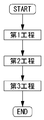
- FIG. 1 is a flowchart illustrating the flow of the method for manufacturing a functional resin body according to the present embodiment.
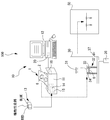
- FIG. 2 is a schematic diagram illustrating a manufacturing system used in the method for manufacturing a functional resin body according to the present embodiment.
- a functional lens is added to the lens 8, which is one of the resin bodies, to add a function of reducing the transmittance in the wavelength region of the blue region using a vapor phase transfer dyeing method.
- the technology of the present disclosure can be applied to the lens 8 regardless of the refractive index.
- the technology of the present disclosure can be applied to lenses having various refractive indexes (for example, low diopter, high diopter, 0 diopter, and the like).
- the techniques exemplified below include resin bodies other than the lens 8 (for example, goggles, cell phone covers, light covers, accessories, toys, films (for example, having a thickness of 400 ⁇ m or less), and plate materials (for example, thicknesses).
- the substrate for function addition 1 exemplified below can also be used in a transfer dyeing process other than the vapor phase transfer dyeing.
- a first step, a second step, and a third step are performed.
- the method for manufacturing a functional resin body according to the present embodiment is performed in the order of a first step, a second step, and a third step.
- the first step is a step of applying a functional dye to a base (for example, the base 2) to obtain a base for adding a function (for example, the base 1 for adding a function).
- the function applied to the function-adding substrate is obtained by heating the function-adding substrate by facing the function-adding substrate obtained in the first step with a resin body (for example, the lens 8).
- the third step is a step of fixing the functional dye to the resin body by heating the resin body to which the functional dye has been attached in the second step.
- the functional dye is a merocyanine-based functional dye that absorbs light in the blue region.
- the method for producing a functional resin body includes, when performing the above process, using the above functional dye, the luminous transmittance is 75% or more, and the average in the blue wavelength region. A function of reducing the transmittance to 10% or less is added to the resin body.
- the method for manufacturing a functional resin body according to the present disclosure includes applying a functional dye having a sublimation property to a merocyanine-based functional dye that absorbs light in a blue region.
- a first step of obtaining a substrate for adding a function a second step of attaching a functional dye to the resin body, and a third step of fixing the functional dye to the resin body.
- a function is added to the resin body such that the luminous transmittance is 75% or more and the average transmittance in the wavelength region of the blue region is 10% or less.
- a resin body having a function of having a luminous transmittance of 75% or more and an average transmittance of 10% or less in a wavelength region of a blue region can be manufactured. That is, for example, a function in which the luminous transmittance is easily 75% or more in a short time and the average transmittance in the blue wavelength region is 10% or less without requiring a complicated process or many processes. Can be produced. Since the luminous transmittance exceeds 75%, the luminous transmittance can be used as a resin body for night operation (for example, a lens for night operation), and the transmittance in the blue wavelength region is reduced. The obtained resin body can be obtained.
- a functional dye can be applied to a substrate, and the functional dye applied to the substrate can be attached to the resin body, so that the functional dye can be used for adding functions to the resin body without waste. That is, it is possible to add a function to the resin body with a smaller number of functional dyes.
- the dye for reducing the transmittance in the wavelength region of the blue region is expensive, the technology of the present disclosure is more useful.
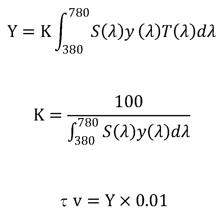
- the luminous transmittance is calculated by the following equation (see JIS T 7331: 2006).
- S ( ⁇ ) indicates the spectral distribution of standard light used for displaying colors.
- y ( ⁇ ) indicates a color matching function in the XYZ color system.
- T ( ⁇ ) indicates the spectral solid angle transmittance.
- the luminous transmittance ( ⁇ V) is obtained by multiplying the distribution of the standard light source D65 by the relative luminosity function in the wavelength range of 380 nm to 780 nm as a denominator, and using a resin body (for example, a lens). Is calculated by multiplying the luminous flux incident through the luminous flux by the relative luminosity function, and multiplying the numerator by 100.
- the luminous transmittance of the resin body is 75% or more, the criterion relating to the luminous transmittance when the resin body is used for night driving can be satisfied.
- an average transmittance of 10% or less indicates that the average value of the transmittance for each wavelength in the blue wavelength region is 10% or less.
- the wavelength range of 380 nm to 500 nm which is generally the wavelength range of the blue region, is taken as an example of the wavelength range of the blue region. That is, in the present embodiment, for example, an average transmittance of 10% or less indicates that the average value of the transmittance at each wavelength in the wavelength range of 380 nm to 500 nm is 10% or less.
- an average transmittance of 10% or less refers to an average wavelength range of 380 nm to 500 nm even if the transmittance of 410 nm to 430 nm, which is the wavelength range of the blue region, exceeds 10%. In the case where the average value of the transmittance at each wavelength is calculated, it may be 10% or less.
- the functional dye a functional dye capable of absorbing light in a blue wavelength range and having a luminous transmittance of 75% or more is used.
- a functional dye (having a maximum absorption peak at 473 nm) that absorbs light in a wavelength region of 400 nm to 500 nm as a wavelength region of a blue region is used.
- the functional dye that absorbs light in the wavelength region of the blue region is not limited to the wavelength region of 400 nm to 500 nm, and an arbitrary wavelength region in the wavelength region of the blue region can be set. it can.
- a functional dye that absorbs light in a specific wavelength range for example, 430 nm to 500 nm
- a wavelength range of 380 nm to 500 nm which is generally a wavelength range of a blue region
- a functional dye that absorbs light in a specific wavelength range for example, 430 nm to 500 nm
- a wavelength range of 380 nm to 500 nm which is generally a wavelength range of a blue region
- a merocyanine-based dye is used as the functional dye that absorbs light in the wavelength region of the blue region.
- the functional dye that absorbs light in the wavelength region of the blue region is not limited to the dye described above, and has a sublimation property and can absorb light in the wavelength region of the blue region. Any functional dye having a function of achieving a ratio of 75% or more may be used.
- At least one functional dye may be used as the functional dye. That is, for example, in the present embodiment, in addition to the merocyanine-based functional dye that absorbs light in the blue region, a function of reducing the transmittance of light in a specific wavelength range is added to the functional resin body. You may make it. In this case, for example, only a merocyanine-based functional dye that absorbs light in the blue region may be used. For example, in this case, in addition to a merocyanine-based functional dye that absorbs light in the blue region, at least one or more functional dyes (for example, one functional dye, two functional dyes, A natural dye, four functional dyes, etc.).
- the first step may be configured to simultaneously apply the plurality of functional dyes to the substrate. Further, for example, when a plurality of functional dyes are used for a resin body, the first step may be configured to apply the plurality of functional dyes to the base at different timings.
- a polycarbonate resin for example, diethylene glycol bisallyl carbonate polymer (CR-39)), a polyurethane resin (Tribex), an allyl resin (for example, allyl diglycol carbonate and its copolymer) Coalesced, diallyl phthalate and copolymers thereof), fumaric acid-based resin (eg, benzyl fumarate copolymer), styrene-based resin, polymethyl acrylate-based resin, fiber-based resin (eg, cellulose propionate), thiourethane
- a function can be added to a resin body made of at least one of a high refractive material such as a resin or thioepoxy, a nylon resin (a polyamide resin), and the like.
- the resin body may be coated with a receiving film on which the functional dye is easily fixed. By coating the resin body with the receiving film, it becomes possible to add functions more easily.
- a sublimable dye for adjusting the color may be used in addition to the functional dye.
- a yellow dye may be used as the sublimable dye.
- a quinophthalone-based functional dye may be used as the yellow dye.
- a function-adding base may be obtained by further applying a sublimable dye, which is a yellow dye for dyeing a resin body and has a sublimation property.
- the sublimable dye applied to the function adding substrate may be sublimated, and the sublimable dye may be attached to the resin body.
- the sublimable dye may be fixed to the resin body by heating the resin body to which the sublimable dye is attached in the second step.
- a function that the luminous transmittance is 75% or more and the transmittance in the entire wavelength region in the blue wavelength region is 15% or less may be added to the resin body. That is, by adding a dye for adjusting the color, it is possible to change the transmittance in a predetermined wavelength range (for example, the transmittance in a blue wavelength range). That is, by adding the sublimable dye for adjusting the color, the transmittance in a predetermined wavelength range (for example, the transmittance in the blue wavelength range) can be finely adjusted by affecting the sublimable dye.
- a yellow dye for dyeing a resin body using a sublimable dye having sublimability and a functional dye, having a luminous transmittance of 75% or more and all wavelengths in a blue wavelength region.
- a function of reducing the transmittance of the region to 10% or less may be added to the resin body.
- the transmittance can be uniformly reduced in the entire wavelength region in the blue wavelength region. That is, if the light has a wavelength peak in the wavelength region of the blue region, the transmittance can be satisfactorily reduced. That is, even when various lights having different wavelength peaks are irradiated, the transmittance can be satisfactorily reduced for each light.
- the luminous transmittance is 75% or more, and the blue region is used.
- the first step may be configured to simultaneously apply the functional dye and the sublimable dye to the substrate.
- the first step may be configured to apply the functional dye and the sublimable dye to the substrate at different timings.
- the sublimable dye another sublimable dye may be used in addition to the yellow dye.
- the sublimable dye may further include at least one of a red dye and a blue dye.
- a function can be added and an arbitrary color can be added, so that a functional resin body dyed in a desired color can be easily obtained.
- colors other than the above three colors may be used. For example, a mixed color (green, purple, etc.) dye may be used.
- the manufacturing system 100 is used to perform each step in the method for manufacturing a functional resin body.
- a schematic configuration of the manufacturing system 100 according to the present embodiment will be described with reference to FIG.
- the manufacturing system 100 of the present embodiment includes a dye coating device 10, a vapor deposition device 30, and a dye fixing device (fixing device) 50.
- the dye coating device 10 is used.
- the dye coating apparatus 10 applies a functional dye deposited on a resin body (the lens 8 in the present embodiment) to the base 2 to obtain the function adding base 1 coated with the functional dye.
- the vapor deposition device 30 is used.
- the vapor deposition apparatus 30 causes the functional dye to be sublimated by applying the functional dye to the resin body by heating the functional additive base by facing the functional base 1 to the resin body.
- the fixing device 50 is used.
- the fixing device 50 is used for fixing the functional dye to the resin body by heating the resin body to which the functional dye is attached.
- a functional dye is applied to the substrate 2 by the dye application device 10 to obtain the function-added substrate 1 (manufacture).
- the dye coating device 10 forms the dye portion 6 by attaching a functional dye to be deposited on the lens 8 to the base 2 later.
- the base 2 is a medium that temporarily holds a functional dye used for dyeing the lens 8. The detailed description of the base 2 will be described later.
- a printing device is used as the dye application device 10.
- a dyeing ink containing a functional dye is printed on the base 2 using a printing apparatus, thereby obtaining the function-added base 1.
- This makes it easy to control the amount of the functional dye to be applied with high accuracy, so that the functional dye can be easily and uniformly applied to the substrate 2.
- the number of functional dyes used can be reduced.
- the step of drying the ink printed by the printing apparatus is performed, so that the functional dye is held more firmly.
- a sublimable dye for adjusting the color of a functional resin body is used in addition to the functional dye.
- the functional dye may be used.
- at least one of red, blue, and yellow dyes is used as the sublimable dye.
- the functional resin body can be satisfactorily dyed in various colors. That is, it is possible to easily obtain the function-adding substrate 1 that can satisfactorily dye the functional resin body with various colors.
- colors other than these three colors may be used. For example, a mixed color (green, purple, etc.) may be used.
- the functional dye may be dissolved in a solvent of the ink.
- the ink for adding a function is put into an ink container (for example, an ink pack, an ink cartridge, or the like) for an ink jet printer, and the ink container is mounted on the mounting portion 14 of the ink jet printer 11.
- an ink container for example, an ink pack, an ink cartridge, or the like
- the ink container is mounted on the mounting portion 14 of the ink jet printer 11.
- the ink cartridge 13 is used as an ink container will be described as an example.
- the ink for adding a function is put into an ink cartridge 13 for an ink jet printer, and the cartridge 13 is mounted on a mounting portion 14 of the ink jet printer 11.
- a functional dye that reduces the transmittance of light in a blue wavelength region is used as the functional dye.
- a sublimable dye is used together with the functional dye.
- the sublimable dye may be dissolved in a solvent of the ink, for example, similarly to the ink for adding a function.
- the dyeing ink has at least one of red, blue, and yellow dyeing inks.
- the dyeing ink is put into an ink container (for example, an ink pack, an ink cartridge, or the like) for an ink jet printer, and the ink container is mounted on the mounting portion 14 of the ink jet printer 11.
- an ink container for example, an ink pack, an ink cartridge, or the like
- the dyeing ink is put into each of the ink cartridges 13 for the ink jet printer, and the cartridge 13 is mounted on the mounting portion 14 of the ink jet printer 11.
- a commercially available inkjet printer 11 can be used.
- the sublimable dye a dye having heat resistance enough to withstand heat during sublimation is preferably used.
- a quinophthalone-based sublimable dye or an anthraquinone-based sublimable dye is used. Tachi).
- a configuration in which the function-adding ink and the dyeing ink are placed in separate ink ink containers is taken as an example, but is not limited thereto. Not done.
- a mixed ink obtained by mixing a function adding ink and a dyeing ink may be used.
- the mixed ink may be put in the ink container.
- the injection printer 11 for example, a case where the injection printer 11 is used as a printing device will be described as an example.
- the functional dye is applied to the base 2 by printing using the inkjet printer 11.
- the injection printer 11 includes a mounting unit 14, an inkjet head 15, and a control unit (control unit) 16.
- the injection printer 11 is not limited to the above configuration.
- the mounting unit 14 includes an ink container for a function-adding ink containing a functional dye (for example, an ink cartridge 13 described later) and an ink container for a dyeing ink containing a sublimable dye (for example, an ink described later). And the cartridge 13).
- the inkjet head 15 discharges the function-adding ink and the dyeing ink toward the base 2 from the ink container for the function-adding ink and the ink container for the dyeing ink provided in the mounting unit 14.
- the control unit 16 controls the driving of the inkjet heads 15 so that the function-adding ink and the dyeing ink are ejected independently from the respective inkjet heads 15.
- the control unit 16 discharges the function-adding ink and the dyeing ink from the inkjet head 15 at the same time, and the functional dye and the sublimable dye are discharged.
- “simultaneously” means that the functional dye and the sublimable dye can be applied to the substrate 2 in a mixed state, and includes substantially simultaneously.
- the control unit 16 discharges the function-adding ink and the dyeing ink from the inkjet head 15 at different timings so that the functional dye and the sublimable ink are discharged.
- a dye may be applied to the substrate 2.
- one of the function adding ink and the dyeing ink may be ejected first, and then the other may be ejected thereafter.
- a dyeing ink containing a functional dye for adding a function of reducing the transmittance of light in a blue wavelength range, and a sublimable dye for adjusting the color In order to print the dye ink containing the dye on the base 2, the discharge amount of each dye ink to be printed is adjusted using a personal computer 12 (hereinafter referred to as PC).
- PC personal computer 12
- the amount of the function-adding ink containing the functional dye and the amount of the dye ink containing the sublimable dye for adjusting the color are stored in the memory 20 as color data.
- the color density is stored in the memory 20 as the color data. For example, when an operator selects desired color data, it is possible to call up the color data from the memory 20 and add the same function and reproduce the same color as many times as necessary. Further, for example, since the shading of colors is digitally managed, a color having the same density can be obtained as many times as necessary. Note that, for example, the concentration gradient can be obtained by a gradation function provided in draw software or the like.
- a gradation according to a preference may be set in advance, and may be stored in the PC 12 as original gradation data (color data).
- original gradation data color data
- a gradation pattern having a density gradient will be described as an example of a desired color, but the present invention is not limited to this.
- the desired color various designs (for example, a single color design, an image, etc.) can be printed.
- the concentration of the functional dye may be changeable.
- the transmittance of light can be changed by changing the concentration of the functional dye.
- the concentration of the functional dye may be selectable, and color data for applying the functional dye at the selected concentration may be selected for each concentration of the functional dye.
- the substrate 2 on which the functional dye is printed by a printing apparatus may be a configuration using paper, a metal plate (for example, aluminum, iron, copper, or the like), glass, or the like.
- the base 2 will be described using paper as an example.
- a sheet-shaped base is used as the base 2.
- the printing apparatus will be described by taking the injection printer 11 as an example.
- the substrate 2 is inserted into the injection printer 11, and the operation of the PC 12 is performed to add the functions set in advance, and to print the respective inks so as to obtain the color and the color density.
- the printing device may be configured to apply a functional dye to the base 2 by printing using a laser printer.
- the functional dye is attached to the base 2 by using a toner and a laser printer.
- the configuration in which the functional dye is applied to the base 2 using the printing device as the dye attaching portion 10 is described as an example, but the present invention is not limited to this.
- the dye coating device 10 may have any configuration as long as the functional dye can be coated on the base 2.
- the dye application device 10 may cause the ink for function addition to adhere to the base for function addition 1 by driving a dispenser (liquid metering device), a roller, or the like.
- the function adding ink may be applied to the function adding base 1 by a worker using a brush, a roller, a spray, or the like. In addition, you may make it apply
- the functional dye When the functional dye is applied to the substrate 2, the functional dye may be applied at least once or more.
- the functional dye may be applied to the base 2 by one application (for example, one printing), or the functional dye may be applied by a plurality of applications (for example, multiple printing). It may be applied to the base 2. That is, the number of times the functional dye is applied to the substrate 2 may be changed depending on the color and the density.
- the functional dye a functional dye capable of absorbing light in a blue wavelength region and having a luminous transmittance of 75% or more is used.
- a functional dye (having a maximum absorption peak at 473 nm) that absorbs light in a wavelength region of 400 nm to 500 nm as a wavelength region of a blue region is used.
- the functional dye that absorbs light in the wavelength region of the blue region is not limited to the wavelength region of 400 nm to 500 nm, and an arbitrary wavelength region in the wavelength region of the blue region can be set. it can.
- a functional dye that absorbs light in a specific wavelength range for example, 430 nm to 500 nm
- a wavelength range of 380 nm to 500 nm which is generally a wavelength range of a blue region
- a functional dye that absorbs light in a specific wavelength range for example, 430 nm to 500 nm
- a wavelength range of 380 nm to 500 nm which is generally a wavelength range of a blue region
- a merocyanine-based dye is used as the functional dye that absorbs light in the wavelength region of the blue region.
- the functional dye that absorbs light in the wavelength region of the blue region is not limited to the dye described above, and has a sublimation property and can absorb light in the wavelength region of the blue region. Any functional dye having a function of achieving a ratio of 75% or more may be used.
- the function-adding substrate 1 on which the functional dye is applied is obtained by the inkjet printer 11.
- the second step is performed using the function-adding substrate 1 obtained in the first step.
- the function-adding base 1 obtained in the first step is made to face a resin body (in the present embodiment, the lens 8), and the function-adding base 1 is heated.
- the functional dye and the sublimable dye applied to the substrate 1 are sublimated, and the functional dye and the sublimable dye are attached to the lens 8.
- the vapor deposition device 30 is used.
- the vapor deposition device 30 sublimates the functional dye and the sublimable dye toward the functional lens 8 by heating the functional dye and the sublimable dye attached to the function-adding substrate 1 with electromagnetic waves. As a result, the functional dye and the sublimable dye are deposited on the functional lens 8.
- the functional lens 8 may be formed with various layers such as a receptor film for facilitating fixing of a functional dye and a sublimable dye in a third step described later.
- the vapor deposition device 30 of the present embodiment includes an electromagnetic wave generator 31, a vapor deposition jig 32, a pump 36, and a valve 37.
- the configuration of the vapor deposition device 30 is not limited to the above configuration. In the present embodiment, the case where the functional dye and the sublimable dye are vapor-deposited on the functional lens 8 will be described as an example, but the case where only the functional dye is vapor-deposited on the functional lens 8 will be described. Good.
- the electromagnetic wave generator 31 generates an electromagnetic wave.
- a halogen lamp that generates infrared rays is used as the electromagnetic wave generator 31.
- the electromagnetic wave generator 31 may be any unit that generates an electromagnetic wave. Therefore, in place of the halogen lamp, a configuration for generating electromagnetic waves of other wavelengths such as ultraviolet rays and microwaves may be used.
- the vapor deposition device 30 can raise the temperature of the functional dye in a short time by irradiating the base for function addition 1 with electromagnetic waves.
- the vapor deposition device 30 of the present embodiment can uniformly heat the functional dye and the sublimable dye by the electromagnetic waves from the electromagnetic wave generator 31 that is separated from the function-adding base 1.
- the jig for vapor deposition 32 holds the base for function addition 1 and the lens 8.
- the vapor deposition jig 32 of the present embodiment includes a lens support 33 and a base support 34.
- the lens support 33 includes a cylindrical base and a mounting table arranged inside the base.
- the lens 8 is supported by the mounting table of the lens support 33 while being surrounded by the base.
- the base support 34 is located at the upper end of the cylindrical base and supports the function-adding base 1 above the lens 8.
- a plate-shaped glass is further placed on the upper surface of the function-adding substrate 1 held by the substrate supporting portion 34, so that the sublimated functional dye is placed.
- the sublimation dye may be prevented from spreading to the back side of the function-adding substrate 1.
- the function-adding substrate 1 is arranged such that the surface to which the functional dye and the sublimable dye are attached faces the functional lens 8.
- the base for function addition 1 since the base for function addition 1 is supported above the function lens 8, the base for function addition 1 is placed on the base support part 34 so that the dye-adhering surface faces downward.
- the function-adding base 1 and the lens 8 when they are opposed to each other, they may be opposed in a non-contact manner (for example, 2 mm to 30 mm).
- the function-adding base 1 obtained in the first step is applied to the function-adding base 1 by heating the function-adding base 1 by facing the lens 8 in a non-contact manner.
- the functional dye and the sublimable dye thus obtained may be sublimated, and the functional dye and the sublimable dye may be attached to the lens 8.
- by opposing the substrate in a non-contact manner it is possible to suppress the conduction of heat when the substrate is heated to sublimate the functional dye and the sublimable dye to the resin body. Thereby, it is possible to suppress the resin body from being discolored, contracted, or the like due to heat.
- the functional dye and the sublimable dye can be sufficiently dispersed and adhered to the resin body. it can. As a result, variation in light transmittance and color unevenness in the resin body can be further suppressed, and a dyed resin body with good functions can be manufactured.
- the gradation pattern when a gradation pattern is applied to the substrate in the color of the resin body, the gradation pattern can be preferably reproduced on the resin body.
- the function-adding base 1 and the lens 8 are opposed to each other, they may be opposed to each other in a state where they are in contact with each other.
- the pump 36 discharges the gas inside the vapor deposition device 30 to the outside, and lowers the pressure inside the vapor deposition device 30. That is, for example, the pump 36 discharges the gas inside the vapor deposition device 30 to the outside, and makes the inside of the vapor deposition device 30 a predetermined degree of vacuum.
- the inside of the vapor deposition device 30 is set to a predetermined degree of vacuum by the pump 36 to perform the attaching operation.
- the inside of the vapor deposition device 30 is set to a predetermined vacuum state.
- the present invention is not limited to this. It is also possible to perform the attachment operation inside the vapor deposition device 30 under normal pressure.
- the function-adding base 1 is heated from above using the electromagnetic wave generator 31 to sublimate the functional dye and the sublimable dye.
- the heating temperature is lower than 100 ° C. on the function-adding substrate 1, the functional dye and the sublimable dye are difficult to sublimate from the function-adding substrate 1.
- the heating temperature is preferably between 100 and 250 ° C., but it is preferable to select the highest possible temperature according to the material of the lens 8.
- the second step may be a step of performing at least one evaporation.
- the vapor deposition may be repeated a plurality of times (for example, twice) by using a plurality of function-adding bases 1.
- Such a method is useful, for example, when the amount of dye to be applied to the resin body is large, or when a plurality of types (for example, five types) of dyes are used.
- ⁇ Third step> For example, when the second step is completed, the third step is performed.
- the third step will be described.
- the lens 8 to which the functional dye and the sublimable dye are attached in the second step is heated to fix the functional dye and the sublimable dye.
- the functional dye may be fixed.
- the dye fixing device 50 fixes the functional dye and the sublimable dye to the lens 8 by heating the lens 8 on which the functional dye and the sublimable dye are deposited. For example, when the lens 8 is heated, the functional dye and the sublimable dye are fixed to the lens 8. Thus, the function of reducing the transmittance of light in a specific wavelength range is added to the lens 8 and the color of the lens 8 can be adjusted.
- an oven is used as the dye fixing device 50. If an oven (especially a blow-type constant temperature incubator) is used, the temperature of the lens 8 gradually increases over a long period of time, so that a temperature difference hardly occurs. Therefore, the functional dye and the sublimable dye are easily fixed to the lens 8 uniformly.
- the functional dye and the sublimable dye may be fixed by heating under normal pressure.
- the third step may be performed under a different atmospheric pressure.
- the worker attaches the functional dye and the sublimable dye to the lens 8 in the vapor deposition device 30 and then takes out the lens 8 to which the functional dye and the sublimable dye are attached.
- an operator puts the lens 8 into the dye fixing device 50 and heats it under normal pressure to fix the functional dye and the sublimable dye.
- the heating is performed at a temperature at which the lens 8 is not deformed and sufficient color can be formed.
- the heating temperature may be preferably 110 ° C. or more and 160 ° C. or less (110 ° C. to 160 ° C.).
- the resin body to which the functional dye and the sublimable dye are attached in the second step is heated at a temperature of 110 ° C. to 160 ° C. May be fixed.
- the functional dye and the sublimable dye can easily reach the inside of the resin body (the lens 8 in the present embodiment).
- a function of reducing the transmittance of light in a specific wavelength range can be satisfactorily added, and dyeing can be performed more favorably.
- color omission from the dyed (color-adjusted) resin body (the lens 8 in the present embodiment) can be suppressed.
- by fixing the functional dye and the sublimable dye at a temperature of 160 ° C. or lower in the third step it is possible to prevent the resin body from being excessively heated, and it is more difficult to deform the resin body. can do.
- the above-mentioned temperature is described as a temperature at which the deformation of the resin body is difficult, but the temperature is not limited to this. For example, in the case of a resin body having high heat resistance, deformation can be made difficult even when fixing is performed at a higher temperature according to the resin body.
- the heating temperature is more preferably 120 ° C. or more and 155 ° C. or less.
- the functional dye and the sublimable dye are heated by heating the resin body to which the functional dye and the sublimable dye are attached in the second step at a temperature of 120 ° C. to 155 ° C. May be fixed.
- a function of reducing the transmittance of light in a specific wavelength range can be satisfactorily added.
- Dyeing can be performed.
- color loss from the dyed resin body can be further suppressed, and deformation of the resin body can be further suppressed.
- the method for manufacturing a functional resin body according to the present disclosure includes applying a functional dye having a sublimation property to a base, which is a merocyanine-based functional dye that absorbs light in a blue region.
- a first step of obtaining a substrate for adding a function a second step of attaching a functional dye to the resin body, and a third step of fixing the functional dye to the resin body.
- a function is added to the resin body such that the luminous transmittance is 75% or more and the average transmittance in the wavelength region of the blue region is 10% or less.
- a resin body having a function of having a luminous transmittance of 75% or more and an average transmittance of 10% or less in a wavelength region of a blue region can be manufactured. That is, for example, a function in which the luminous transmittance is easily 75% or more in a short time and the average transmittance in the blue wavelength region is 10% or less without requiring a complicated process or many processes. Can be produced. Since the luminous transmittance exceeds 75%, the luminous transmittance can be used as a resin body for night operation (for example, a lens for night operation), and the transmittance in the blue wavelength region is reduced. The obtained resin body can be obtained.
- a functional dye can be applied to a substrate, and the functional dye applied to the substrate can be attached to the resin body, so that the functional dye can be used for adding functions to the resin body without waste. That is, it is possible to add a function to the resin body with a smaller number of functional dyes.
- the dye for reducing the transmittance in the wavelength region of the blue region is expensive, the technology of the present disclosure is more useful.
- the shape (printing shape) of the dye portion 6 is circular, but is not limited thereto, and may be, for example, a semicircular shape or another shape (for example, square shape). Good.
- the method for heating the function-adding substrate 1 is described as being performed from above, but is not limited thereto.
- the functional dye can be similarly sublimated by heating from the side or from below.
- the structure of the dye fixing device 50 can be changed.
- the dye fixing device 50 may heat the lens 8 by scanning a laser on the lens 8.
- the dye fixing device 50 can intentionally generate a temperature difference according to the position of the lens 8.
- the dye fixing device 50 may control laser scanning in accordance with a target gradation state, for example, in a case where gradation dyeing or a functional dye is applied in a gradation form.
- the dye fixing device 50 may control laser scanning according to the thickness of the lens 8 or the like so that the temperature of each part of the lens 8 becomes a desired temperature.
- the dye fixing device 50 may heat the lens by directly irradiating the lens 8 with an electromagnetic wave.
- two or more of the steps (for example, the first step, the second step, the third step, etc.) performed in each of the dye coating apparatus 10, the vapor deposition apparatus 30, and the dye fixing apparatus 50 are performed by one apparatus. May be done.
- a dyeing apparatus that performs both the second step performed by the vapor deposition device 30 and the third step performed by the dye fixing device 50 may be used.
- the same heating means for example, an infrared heater or the like
- the dyeing apparatus may automatically perform a plurality of steps (for example, from the second step to the third step) in a series of flows.
- the transmittance of light in a specific wavelength region may not be reduced uniformly. There is. Therefore, for example, the region where the functional dye is applied may be different from the region where the other dye is applied.
- the functional dye may be fixed to the entire resin body, and another dye different from the functional dye may be fixed to a part of the resin body.
- the functional resin body may be further coated (for example, a hard coat, an antireflection coat, an antifouling coat, and the like).
- a specific function of the functional resin body may be improved by performing coating.
- Comparative Example 1 a functional dye was immersed in a resin body using a dip dyeing method to obtain a functional resin body.
- Comparative Examples 2 to 4 a sublimable dye was adhered to the resin body without using a functional dye, and the resin body having the sublimable dye adhered to the surface was heated. was fixed on a resin body to obtain a dyed resin body.
- Comparative Examples 5 to 7 coating treatment was performed on the dyed resin bodies obtained in Comparative Examples 2 to 4 to obtain coated dyed resin bodies. The wavelength transmittances of the functional resin bodies and the dyed resin bodies obtained in the experimental examples and the comparative examples were evaluated.
- a functional dye capable of absorbing light in the wavelength range of 430 nm to 500 nm was used as the wavelength range of the blue region.
- a dyeing ink used for a printer is prepared.
- the functional dye FDB-006 ink (Yamada Chemical Industry Co., Ltd.), which is a merocyanine dye capable of absorbing light in the wavelength range of 430 nm to 500 nm, was used.
- a functional dye, pure water, and a dispersant were placed in a container, and sufficiently stirred to produce a dyeing ink.
- Demol MS Karl MS (Kao Corporation) was used as a dispersant.
- the composition ratio of the dye, the dispersant, and pure water was 6.0% by weight of the dye, 2.5% by weight of the dispersant, and 91.5% by weight of pure water.
- the amount of the functional dye is preferably 0.1 to 20% by weight, more preferably 0.5 to 10% by weight.
- the amount of the functional dye is not limited to the above-mentioned weight%, and can be used in any amount.
- the amount of the functional dye is less than 0.1% by weight, the dye is difficult to fix, and a desired concentration may not be obtained. If the amount of the functional dye exceeds 20% by weight, the dispersibility of the functional dye may be deteriorated.
- the functional dye to be used does not decompose by heat and must have heat resistance. In this experimental example, the amount of the functional dye was 6.0% by weight.
- the container containing the dyeing ink After thoroughly dispersing the dispersant to disperse the functional dye, place the container containing the dyeing ink in the container containing water for cooling, and perform the treatment for the specified time with an ultrasonic homogenizer to obtain the functional dye. To the desired particle size. Thereafter, the dyeing ink is suction-filtered with a filter having a pore size of about 1 ⁇ m (glass fiber filter paper GF / B) to remove particles having a large particle size and dust. Thereafter, pure water is added and adjusted so as to have a designated ink concentration, and if necessary, a humectant and a surfactant for adjusting surface tension are added to prepare a function-adding ink. Although an ultrasonic homogenizer was used for dispersing this time, a micronizing device such as a bead mill may be used. In this way, a function-adding ink is manufactured.
- a filter having a pore size of about 1 ⁇ m glass fiber filter paper GF
- the inside of the ink cartridge for the (EPSON @ PX-6250S) function-adding ink of the printer was thoroughly washed, and then the prepared function-adding ink containing the functional dye was charged and set in the printer. After repeating the cleaning many times, it was confirmed that the ink was switched, and the printing software TTS-PS2 (Nidek Co., Ltd.) was applied to a substrate (high quality PPC paper) with a paper thickness of 100 ⁇ m and a black back surface.
- ⁇ Dyeing was performed using the thus obtained substrate for adding functions.
- the function-imparting substrate was attached to a dyeing jig in a vapor deposition apparatus (NTM-TTM-1000), and a functional dye was vapor-deposited on the MR8 lens (S-0.00).
- the distance between the stained surface side of the MR8 lens and the substrate for adding functions was 15 mm.
- the pressure in the vapor deposition apparatus was reduced to 60 Pa by a pump
- the surface temperature of the substrate for function addition was heated to 200 ° C. by a heating unit (a halogen lamp was used in this experimental example).
- the temperature near the substrate for function addition was measured by a temperature sensor (not shown), and when the temperature reached 200 ° C., the power of the halogen lamp was turned off, and the functional dye was sublimated and adhered.
- the luminous transmittance was calculated by calculating the transmittance in the wavelength region of 380 to 780 nm in the blue region, and substituting the calculated transmittance in each wavelength region into Equation 1 above.
- Luminous transmittance is 75% or more: ⁇ Luminous transmittance is greater than 75%: ⁇ [Evaluation of relative visibility decay rate Q value for signal light recognition (see JIS T 7330)] It has Q value for all signal light of red signal light, yellow signal light, green signal light and blue signal light: ⁇ Q value for all signal light of red signal light, yellow signal light, green signal light and blue signal light Not: ⁇ ⁇ Experimental example 2>
- a yellow sublimable dye for adjusting the color was prepared, and the function was added to the MR8 lens in the same manner as in Experimental Example 1, except that the function was added and the color was adjusted.
- a substrate for adding functions was manufactured.
- a function was added to the MR8 lens using the manufactured substrate for adding function, and the same evaluation as in Experimental Example 1 was performed. Table 1 shows the above results.
- Example 5 A function was added to the MR8 lens and evaluation was performed in the same manner as in Experimental Example 2 except that a coating process was performed on the functional MR8 lens obtained by adding a function to the MR8 lens.
- a hard coat film and an anti-reflection film were formed on the manufactured functional MR8 lens to complete a functional MR8 lens with a coating.
- the hard coat film was formed by applying a silicone-based thermosetting hard coat liquid by an immersion method, and then heating.
- the antireflection film is deposited by a vacuum deposition method at a degree of vacuum of 1.0 ⁇ 10 ⁇ 3 Pa or less and an internal temperature of the deposition machine of 70 ° C.
- a SiO2 film was formed on the second layer at 60 nm, a ZrO2 film was formed on the third layer at 120 nm, a SiO2 film was formed on the fourth layer at 110 nm, and the four layers were formed as an antireflection film. After completing the coated functional MR8 lens, the same evaluation as in Experimental Example 1 was performed. Table 1 shows the results.
- Example 6 A functional MR8 lens was coated in the same manner as in Experimental Example 5 except that the functional MR8 lens to which the function was added was replaced with the functional MR8 lens manufactured in Experimental Example 3, and the same evaluation as in Experimental Example 1 was performed. . Table 1 shows the results.
- Example 7 A functional MR8 lens was coated in the same manner as in Experimental Example 5 except that the functional MR8 lens to which the function was added was replaced with the functional MR8 lens manufactured in Experimental Example 4, and the same evaluation as in Experimental Example 1 was performed. Table 1 shows the results.
- a functional MR8 lens was produced by a conventional dip dyeing method. 60 g of FDB-006 (Yamada Chemical Industry Co., Ltd.), 30 g of Demol MS (Kao Corporation), and 3 g of Succinol (Senka Corporation) are placed in a 1 L stainless steel beaker, and then 60 g of water at about 70 ° C. is added. Stir well until homogeneously mixed.
- a function-adding solution having a concentration of FDB-006 of 0.6%.
- the concentration is a function-adding liquid having a concentration about twice as high as the concentration of the dye used in the conventional permeation method.
- the liquid for function addition in a stainless beaker was maintained at 95 ° C. while stirring in a water bath, and the function was added by immersing the MR8 lens and leaving it for 60 minutes.
- the average transmittance of light in the blue wavelength range from 380 nm to 500 nm is 10% or less.
- the transmittance is 75% or more, a function that hardly transmits light in the wavelength region of the blue region can be added, so that it was confirmed that a resin body having a higher function could be provided. .
- the luminous transmittance is 75% or more, and It was confirmed that a function of providing a transmittance of 5% or less for each wavelength of 410 nm to 430 nm in the blue wavelength region could be added to the resin body. That is, by using a yellow dye, the wavelength range from 410 nm to 430 nm was higher when the yellow dye was not added, as compared with the transmittance in the other blue region. Also, it was confirmed that the transmittance in Example 2 was able to be reduced to the same level as the transmittance in the wavelength region of the other blue region.
- this resin body has light having a wavelength peak in the wavelength region of the blue region, it is possible to satisfactorily reduce the transmittance for almost all wavelengths and obtain a more effective resin body. It was shown that it could be done. That is, the resin body can satisfactorily reduce the transmittance for each light even in the case of irradiating various lights having different wavelength peaks in the wavelength region of almost the entire blue region. It has been shown.
- the average transmittance in the wavelength region of the blue region of 380 nm to 500 nm was obtained. Can be set to 5% or less, and the transmittance can be reduced more effectively. Further, as shown in Experimental Examples 2 to 7 in Table 1, the average transmittance in the wavelength range of 400 nm to 490 nm can be set to 1% or less, and the transmittance can be more effectively reduced. it can.
Landscapes
- Engineering & Computer Science (AREA)
- Physics & Mathematics (AREA)
- Chemical & Material Sciences (AREA)
- Ophthalmology & Optometry (AREA)
- Health & Medical Sciences (AREA)
- General Physics & Mathematics (AREA)
- Optics & Photonics (AREA)
- Mechanical Engineering (AREA)
- Manufacturing & Machinery (AREA)
- Life Sciences & Earth Sciences (AREA)
- Materials Engineering (AREA)
- Wood Science & Technology (AREA)
- Organic Chemistry (AREA)
- General Health & Medical Sciences (AREA)
- Chemical Kinetics & Catalysis (AREA)
- General Chemical & Material Sciences (AREA)
- Eyeglasses (AREA)
- Optical Filters (AREA)
- Inks, Pencil-Leads, Or Crayons (AREA)
Abstract
樹脂体に対して青色領域の波長域の透過率を低減する機能樹脂体の製造方法であって、青色領域の光の吸収を行うメロシアニン系の機能性染料であって、昇華性を有する機能性染料を、基体に塗布することで、機能付加用基体を取得する第1工程と、第1工程によって取得された機能付加用基体を樹脂体と対向させ、機能付加用基体を加熱することによって、機能性染料を昇華させ、機能性染料を樹脂体に付着させる第2工程と、第2工程によって、機能性染料が付着された樹脂体を加熱することによって、機能性染料を樹脂体に定着させる第3工程と、を備え、視感透過率が75%以上、且つ、青色領域の波長域における平均透過率が10%以下となる機能を樹脂体に付加する。
Description
本開示は、青色領域の波長域の透過率を低減する機能を有する機能樹脂体の製造方法に関する。
従来、樹脂体に特定の波長域の光の透過率を低減することによって、人体に良い影響を与える機能樹脂体が提案されている。例えば、機能樹脂体の一例として、特定の波長域の透過率を低減する機能レンズが挙げられる。例えば、機能レンズとしては、青色光の透過率を低減させることによって、青色光が眼に与える影響を低減するもの(例えば、特許文献1)等が提案されている。
従来、例えば、このような機能樹脂体を製造するための種々の方法が提案されている。例えば、樹脂体に波長を選択的に吸収できる物質を練り込む方法、波長を選択的に吸収できる物質を混合した液の中に樹脂体を所定時間浸漬する方法(浸染法)、樹脂体に対して多層膜を形成する方法等が用いられている。
ところで、青色領域の波長域の透過率を低減した樹脂体が種々の目的で幅広く使われるようになってきている。例えば、近年では、夜間運転用(視感透過率75%以上が条件)で用いることができる青色領域の波長域の透過率を低減した樹脂体も望まれている。しかしながら、青色領域の波長域の透過率を十分に低減(例えば、平均透過率を10%以下)した樹脂体の中で視感透過率75%の樹脂体を製造することは困難であった。
本開示は、上記問題点を鑑み、視感透過率が75%以上、且つ、青色領域の波長域における透過率が低減された機能を有する樹脂体を容易に製造することができる機能樹脂体の製造方法を提供することを目的とする。
上記課題を解決するために、本開示は以下のような構成を備えることを特徴とする。
本開示の第1様態に係る機能樹脂体の製造方法は、樹脂体に対して青色領域の波長域の透過率を低減する機能付き樹脂体の製造方法であって、機能性染料を基体に塗布することで、機能付加用基体を取得する第1工程と、前記第1工程によって取得された前記機能付加用基体を樹脂体と対向させ、前記機能付加用基体を加熱することによって、前記機能付加用基体に塗布された前記機能性染料を昇華させ、前記機能性染料を前記樹脂体に付着させる第2工程と、前記第2工程によって、前記機能性染料が付着された前記樹脂体を加熱することによって、前記機能性染料を前記樹脂体に定着させる第3工程と、を備え、前記機能性染料は、青色領域の光の吸収を行うメロシアニン系の機能性染料であり、前記機能性染料を用いて、視感透過率が75%以上、且つ、青色領域の波長域における平均透過率が10%以下となる機能を前記樹脂体に付加することを特徴とする。
<機能樹脂体の製造システム>
以下、本開示における典型的な実施形態について説明する。例えば、図1は本実施形態の機能樹脂体の製造方法の流れを示したフローチャートである。例えば、図2は本実施形態の機能樹脂体の製造方法に用いる製造システムを示した概略図である。なお、以下では、樹脂体の1つであるレンズ8に対して、気相転写染色法を用いて青色領域の波長域の透過率を低減する機能を付加する機能レンズを製造する場合を例示して説明を行う。なお、レンズ8については、屈折率は問わず、本開示の技術を適用することができる。例えば、本開示の技術は、種々の屈折率(例えば、低ディオプター、高ディオプター、0ディオプター等)のレンズに適用できる。もちろん、以下で例示する技術は、レンズ8以外の樹脂体(例えば、ゴーグル、携帯電話のカバー、ライト用のカバー、アクセサリー、玩具、フィルム(例えば、厚みが400μm以下等)、板材(例えば、厚みが400μm以上等)等のいずれかの成形体等)に対して、気相転写染色法を用いて、青色領域の波長域の透過率を低減する機能を付加する場合にも適用できる。また、以下で例示する機能付加用基体1は、気相転写染色以外の転写染色の工程において使用することも可能である。
以下、本開示における典型的な実施形態について説明する。例えば、図1は本実施形態の機能樹脂体の製造方法の流れを示したフローチャートである。例えば、図2は本実施形態の機能樹脂体の製造方法に用いる製造システムを示した概略図である。なお、以下では、樹脂体の1つであるレンズ8に対して、気相転写染色法を用いて青色領域の波長域の透過率を低減する機能を付加する機能レンズを製造する場合を例示して説明を行う。なお、レンズ8については、屈折率は問わず、本開示の技術を適用することができる。例えば、本開示の技術は、種々の屈折率(例えば、低ディオプター、高ディオプター、0ディオプター等)のレンズに適用できる。もちろん、以下で例示する技術は、レンズ8以外の樹脂体(例えば、ゴーグル、携帯電話のカバー、ライト用のカバー、アクセサリー、玩具、フィルム(例えば、厚みが400μm以下等)、板材(例えば、厚みが400μm以上等)等のいずれかの成形体等)に対して、気相転写染色法を用いて、青色領域の波長域の透過率を低減する機能を付加する場合にも適用できる。また、以下で例示する機能付加用基体1は、気相転写染色以外の転写染色の工程において使用することも可能である。
例えば、本実施形態の機能樹脂体の製造方法においては、第1工程、第2工程、第3工程、が実施される。例えば、本実施形態の機能樹脂体の製造方法は、第1工程、第2工程、第3工程の順序で行われる。例えば、第1工程は、機能性染料を基体(例えば、基体2)に塗布することで、機能付加用基体(例えば、機能付加用基体1)を取得する工程である。例えば、第2工程は、第1工程によって取得された機能付加用基体を樹脂体(例えば、レンズ8)と対向させ、機能付加用基体を加熱することによって、機能付加用基体に塗布された機能性染料を昇華させ、機能性染料を樹脂体に付着させる工程である。例えば、第3工程は、第2工程によって、機能性染料が付着された樹脂体を加熱することによって、機能性染料を樹脂体に定着させる工程である。
例えば、本実施形態において、機能性染料は、青色領域の光の吸収を行うメロシアニン系の機能性染料である。例えば、本実施形態において、機能樹脂体の製造方法は、上記工程を実施する際に、上記の機能性染料を用いて、視感透過率が75%以上、且つ、青色領域の波長域における平均透過率が10%以下となる機能を樹脂体に付加する。
従来、従来法を用いて、樹脂体に機能を付加した場合、青色領域の波長域における平均透過率が10%以下とすることは、時間や染料が多く必要であり、困難である。また、時間や染料を多く用いて、従来法によって、青色領域の波長域における平均透過率を10%以下に近づけた場合に、視感透過率も低減してしまうため、視感透過率を75%以上とすることはできず、このような機能をもつ樹脂体はなかった。すなわち、青色領域における波長域の透過率を大きく低減させた状態とした場合に、視感透過率を75%以上とすることはできず、このような機能をもつ樹脂体はなかった。つまり、樹脂体において、青色領域の波長域における平均透過率と、視感透過率と、において、一方の透過率の効果を出そうとした場合に、他方の効果が出なくなり、これらの双方の効果を満たすことはできなかった。
上記のように、例えば、本開示の機能樹脂体の製造方法は、青色領域の光の吸収を行うメロシアニン系の機能性染料であって、昇華性を有する機能性染料を、基体に塗布することで、機能付加用基体を取得する第1工程と、機能性染料を樹脂体に付着させる第2工程と、機能性染料を樹脂体に定着させる第3工程とを備える。また、例えば、機能性染料を用いて、視感透過率が75%以上、且つ、青色領域の波長域における平均透過率が10%以下となる機能を樹脂体に付加している。これによって、例えば、視感透過率が75%以上、且つ、青色領域の波長域における平均透過率が10%以下となる機能を有する樹脂体を製造することができる。すなわち、例えば、複雑な工程や多くの工程を必要とすることなく、短時間で容易に視感透過率が75%以上、且つ、青色領域の波長域における平均透過率が10%以下となる機能を有する樹脂体を製造することができる。なお、視感透過率が75%を超える樹脂体であるため、夜間運転用の樹脂体(例えば、夜間運転用のレンズ)として用いことが可能であり、青色領域の波長域の透過率を低減した樹脂体を得ることできる。
また、例えば、機能性染料を基体に塗布し、基体に塗布した機能性染料を樹脂体に付着させるため、機能性染料を無駄なく樹脂体への機能付加に利用することができる。すなわち、より少ない機能性染料で樹脂体への機能付加を行うことができる。特に、青色領域の波長域の透過率を低減するための染料が高価であるため、本件開示の技術がより有用となる。
例えば、視感透過率とは、下記式で算出される(JIS T 7331:2006参照)。
例えば、平均透過率が10%以下とは、青色領域の波長域における各波長の透過率の平均値が10%以下であることを示している。なお、例えば、本実施形態においては、青色領域の波長域としては、一般的に青色領域の波長域とされる380nm~500nmの波長域を例に挙げている。すなわち、本実施形態において、例えば、平均透過率が10%以下とは、380nm~500nmの波長域における各波長の透過率の平均値が10%以下であることを示している。一例として、例えば、平均透過率が10%以下とは、青色領域の波長域である410nm~430nmの透過率が10%を超えていた場合であっても、平均として、380nm~500nmの波長域における各波長の透過率の平均値を算出した場合に、10%以下であればよい。
例えば、本実施形態において、機能性染料としては、青色領域の波長域の光の吸収を行うことができ、視感透過率75%以上となる機能を有する機能性染料が用いられる。一例として、例えば、本実施形態において、機能性染料としては、青色領域の波長域として、400nm~500nmの波長域における光の吸収を行う機能性染料(473nmに最大吸収ピークをもつ)が用いられる。もちろん、例えば、青色領域の波長域の光の吸収を行う機能性染料としては、波長域が400nm~500nmの波長域に限定されず、青色領域の波長域における任意の波長域を設定することができる。例えば、一般的に青色領域の波長域とされる380nm~500nmの波長域における特定範囲の波長域(例えば、430nm~500nm等)の光の吸収を行う機能性染料が用いられてもよい。例えば、青色光の透過率を低減させることによって、青色光が眼に与える影響を低減することができる。
例えば、本実施形態において、青色領域の波長域の光を吸収する機能性染料としては、メロシアニン系の染料が用いられる。もちろん、青色領域の波長域の光の吸収を行う機能性染料としては、上記染料に限定されず、昇華性を有し、青色領域の波長域の光の吸収を行うことができ、視感透過率が75%以上となる機能を有する機能性染料であればよい。
例えば、機能性染料は、少なくとも1つ以上の機能性染料が使用されるようにしてもよい。すなわち、例えば、本実施形態において、青色領域の光の吸収を行うメロシアニン系の機能性染料に加え、さらに、特定の波長域の光の透過率を低減させる機能が機能樹脂体に対して付加されるようにしてもよい。この場合、例えば、青色領域の光の吸収を行うメロシアニン系の機能性染料のみが用いられるようにしてもよい。また、例えば、この場合、青色領域の光の吸収を行うメロシアニン系の機能性染料に加え、少なくとも1つ以上の機能性染料(例えば、1つの機能性染料、2つの機能性染料、3つの機能性染料、4つの機能性染料、等)が用いられるようにしてもよい。
例えば、樹脂体に対して、複数の機能性染料を用いる場合に、第1工程は、複数の機能性染料を同時に基体に塗布する構成としてもよい。また、例えば、樹脂体に対して、複数の機能性染料を用いる場合に、第1工程は、複数の機能性染料を異なるタイミングで基体に塗布する構成としてもよい。
なお、例えば、樹脂体としては、ポリカーボネート系樹脂(例えば、ジエチレングリコールビスアリルカーボネート重合体(CR-39))、ポリウレタン系樹脂(トライベックス)、アリル系樹脂(例えば、アリルジグリコールカーボネート及びその共重合体、ジアリルフタレート及びその共重合体)、フマル酸系樹脂(例えば、ベンジルフマレート共重合体)、スチレン系樹脂、ポリメチルアクリレート系樹脂、繊維系樹脂(例えば、セルロースプロピオネート)、チオウレタン系またはチオエポキシ等の高屈折材料、ナイロン系樹脂(ポリアミド系樹脂)、等の少なくともいずれかを材質(材料)とした樹脂体に機能を付加することもできる。なお、例えば、樹脂体には、機能性染料が定着しやすい受容膜をコーティングする構成としてもよい。樹脂体に受容膜をコーティングすることによって、機能の付加をより容易に実施することが可能となる。
なお、例えば、本実施形態において、機能性染料の他に色を調整用の昇華性染料を用いるようにしてもよい。例えば、昇華性染料としては、黄色の染料を用いるようにしてもよい。なお、例えば、黄色の染料のとしては、キノフタロン系機能性染料を用いるようにしてもよい。この場合、例えば、第1工程は、樹脂体を染色するための黄色の染料であって、昇華性を有する昇華性染料を、さらに塗布した機能付加用基体を取得するようにしてもよい。また、例えば、第2工程は、機能付加用基体に塗布された昇華性染料を昇華させ、昇華性染料を樹脂体に付着させるようにしてもよい。また、例えば、第3工程は、第2工程によって、昇華性染料が付着された樹脂体を加熱することによって、昇華性染料を樹脂体に定着させるようにしてもよい。これによって、例えば、視感透過率が75%以上、且つ、青色領域の波長域における全波長域の透過率が15%以下となる機能を樹脂体に付加するようにしてもよい。すなわち、色を調整する染料を付加することによって、所定の波長域の透過率(例えば、青色領域における波長域の透過率)を変化させることができる。つまり、色を調整する昇華性染料を付加することによって、昇華性染料に影響によって、所定の波長域の透過率(例えば、青色領域における波長域の透過率)を微調整することができる。
例えば、樹脂体を染色するための黄色の染料であって、昇華性を有する昇華性染料と機能性染料を用いて、視感透過率が75%以上、且つ、青色領域の波長域における全波長域の透過率が10%以下となる機能を樹脂体に付加するようにしてもよい。これによって、青色領域の波長域において全波長域について均一に透過率を低減させることができる。つまり、青色領域の波長域内に波長のピークがある光であれば、良好に透過率を低減することができる。すなわち、波長のピークが異なる種々の光を照射した場合であっても、各光に対して良好に透過率を低減することができる。
なお、上記のように、樹脂体を染色するための黄色の染料であって、昇華性を有する昇華性染料と機能性染料を用いた場合、視感透過率が75%以上、且つ、青色領域の波長域における410nm~430nmの各波長の透過率が5%以下となる機能を樹脂体に付加することができる。これによって、青色領域の波長域においてほぼ全波長について良好に透過率を低減させることができる。つまり、青色領域のほぼ全領域において、波長のピークが異なる種々の光を照射した場合であっても、各光に対して良好に透過率を低減することができる。
例えば、樹脂体に対して、機能性染料及び昇華性染料を用いる場合に、第1工程は、機能性染料及び昇華性染料を同時に基体に塗布する構成としてもよい。また、例えば、樹脂体に対して、機能性染料及び昇華性染料を用いる場合に、第1工程は、機能性染料及び昇華性染料を異なるタイミングで基体に塗布する構成としてもよい。
なお、例えば、昇華性染料は、黄色の染料に加えの他の昇華性染料を用いるようにしてもよい。この場合、例えば、昇華性染料は、さらに、赤色の染料と、青色の染料と、の少なくともいずれかを含むようにしてもよい。これによって、例えば、機能を付加することができるとともに、任意の色を付加することができるため、容易に所望の色に染色した機能付き樹脂体を得ることができる。なお、昇華性染料としては、上記の3色以外の色が使用されてもよい。例えば、混合色(緑、紫等)の染料が用いられてもよい。
なお、例えば、昇華性染料は、黄色の染料に加えの他の昇華性染料を用いるようにしてもよい。この場合、例えば、昇華性染料は、さらに、赤色の染料と、青色の染料と、の少なくともいずれかを含むようにしてもよい。これによって、例えば、機能を付加することができるとともに、任意の色を付加することができるため、容易に所望の色に染色した機能付き樹脂体を得ることができる。なお、昇華性染料としては、上記の3色以外の色が使用されてもよい。例えば、混合色(緑、紫等)の染料が用いられてもよい。
例えば、本実施形態において、機能樹脂体の製造方法における各工程を実施するために製造システム100が用いられる。例えば、図2を参照して、本実施形態における製造システム100の概略構成について説明する。本実施形態の製造システム100は、染料塗布装置10、蒸着装置30、および染料定着装置(定着装置)50を備える。
例えば、第1工程において、染料塗布装置10が用いられる。例えば、染料塗布装置10は、樹脂体(本実施形態においてはレンズ8)に蒸着される機能性染料を、基体2に塗布させて、機能性染料が塗布された機能付加用基体1を取得するために用いられる。例えば、第2工程において、蒸着装置30が用いられる。例えば、蒸着装置30は、機能付加用基体1を樹脂体と対向させ、機能付加用基体を加熱することによって、機能付加用基体1に塗布された機能性染料を昇華させ、機能性染料を樹脂体に付着させるために用いられる。例えば、第3工程において、定着装置50が用いられる。例えば、定着装置50は、機能性染料が付着された樹脂体を加熱することによって、機能性染料を樹脂体に定着させるために用いられる。
以下、機能樹脂体の製造方法について詳細に説明する。以下では、樹脂体の1つであるレンズ8を気相転写染色法を用いて機能を付加する機能レンズを製造する場合を例示して説明を行う。
<第1工程>
例えば、第1工程は、染料塗布装置10によって、機能性染料を基体2に塗布することで、機能付加用基体1を取得する(製造する)。例えば、第1工程において、染料塗布装置10は、後にレンズ8に蒸着される機能性染料を、基体2に付着させることで、染料部6を形成する。例えば、基体2は、レンズ8の染色に用いられる機能性染料を一旦保持する媒体である。基体2の詳細な説明については後述する。
例えば、第1工程は、染料塗布装置10によって、機能性染料を基体2に塗布することで、機能付加用基体1を取得する(製造する)。例えば、第1工程において、染料塗布装置10は、後にレンズ8に蒸着される機能性染料を、基体2に付着させることで、染料部6を形成する。例えば、基体2は、レンズ8の染色に用いられる機能性染料を一旦保持する媒体である。基体2の詳細な説明については後述する。
本実施形態において、例えば、染料塗布装置10として、印刷装置が用いられる。例えば、本実施形態において、第1工程では、機能性染料が含有された染色用インクを印刷装置を用いて、基体2に印刷することによって、機能付加用基体1を取得する。これによって、機能性染料の塗布量を精度よくコントロールしやすくなり、基体2に対し機能性染料を容易により均一に塗布することができる。さらに、印刷装置を用いることで、使用する機能性染料が削減される。本実施形態では、印刷装置によって印刷されたインクを乾燥させる工程が行われることで、機能性染料がさらに強固に保持される。
なお、本実施形態においては、機能性染料の他に、機能樹脂体の色を調整するための昇華性染料を用いる場合を例に挙げて説明する。もちろん、機能性染料のみを用いるようにしてもよい。例えば、本実施形態において、昇華性染料は、赤色、青色、及び黄色の少なくともいずれかの染料が使用される。例えば、赤色、青色、及び黄色の少なくともいずれかの染料に加えて、機能性染料が吐出できることによって、機能樹脂体を種々の色にて良好に染色することができる。すなわち、機能樹脂体を種々の色にて良好に染色することができる機能付加用基体1を容易に取得することができる。もちろん、これら3色以外の色が使用されてもよい。例えば、混合色(緑、紫等)が用いられてもよい。
なお、例えば、本実施形態において、機能性染料は、インクの溶媒に溶解されていてもよい。例えば、この機能付加用インクをインクジェットプリンタ用のインク容器(例えば、インクパック、インクカートリッジ等)に入れ、インクジェットプリンタ11の装着部14にこのインク容器を装着する。なお、本実施形態においては、インク容器としてインクカートリッジ13が用いられる場合を例に挙げて説明する。例えば、機能付加用インクをインクジェットプリンタ用のインクカートリッジ13に入れ、インクジェットプリンタ11の装着部14にこのカートリッジ13を装着する。なお、例えば、本実施形態において、機能性染料としては、青色領域の波長域の光の透過率を低減させる機能性染料が用いられる。
なお、例えば、本実施形態において、機能性染料とともに、昇華性染料が使用される。なお、例えば、機能付加用インクと同様に、昇華性染料はインクの溶媒に溶解されていてもよい。本実施形態において、例えば、染色用インクは、赤色、青色、及び黄色の少なくともいずれか1つの染色用インクを有する。例えば、この染色用インクをインクジェットプリンタ用のインク容器(例えば、インクパック、インクカートリッジ等)に入れ、インクジェットプリンタ11の装着部14にこのインク容器を装着する。なお、本実施形態においては、インク容器としてインクカートリッジ13が用いられる場合を例に挙げて説明する。例えば、染色用インクをインクジェットプリンタ用のインクカートリッジ13にそれぞれ入れ、インクジェットプリンタ11の装着部14にこのカートリッジ13を装着する。例えば、インクジェットプリンタ11は市販のものが使用可能である。なお、例えば、昇華性染料は、昇華時の熱に耐え得る耐熱性を有するものが用いられることが好ましい。一例として、本実施形態では、キノフタロン系昇華性染料またはアントラキノン系昇華性染料が用いられる(例えば、染料の一例については、特開2004-326018号公報、特開2003-185982号公報等を参照されたし)。
例えば、本実施形態においては、機能付加用インクと、染色用インクと、が別々のインクインク容器(本実施形態においては、インクカートリッジ13)に入れられる構成を例に挙げているがこれに限定されない。例えば、機能付加用インクと、染色用インクと、が混合された混合インクが用いられるようにしてもよい。この場合、例えば、混合インクがインク容器に入れられるようにしてもよい。
本実施形態において、例えば、印刷装置として、インジェクトプリンタ11を用いる場合を例に挙げて説明する。この場合、例えば、インクジェットプリンタ11による印刷によって、基体2に対し機能性染料が塗布される。本実施形態において、例えば、インジェクトプリンタ11は、装着部14と、インクジェットヘッド15と、制御手段(制御部)16と、を備える。もちろん、インジェクトプリンタ11としては、上記構成に限定されない。
例えば、装着部14は、機能性染料を含有する機能付加用インクのインク容器(例えば、後述するインクカートリッジ13等)と、昇華性染料を含有する染色用インクのインク容器(例えば、後述するインクカートリッジ13等)と、を装着する。例えば、インクジェットヘッド15は、装着部14にされた機能付加用インクのインク容器と、染色用インクのインク容器と、から機能付加用インクと染色用インクを基体2に向けて吐出する。これによって、基体2に機能付加用インクと染色用インクを印刷する。例えば、制御部16は、インクジェットヘッド15の駆動を制御して、機能付加用インクと、染色用インクと、をそれぞれのインクジェットヘッド15から独立して吐出させる。
なお、例えば、機能付加用インクとともに、染色用インクを吐出させる場合に、制御部16は、インクジェットヘッド15から機能付加用インクと染色用インクとを同時に吐出させ、機能性染料と昇華性染料を基体2に混合された状態で塗布させるようにしてもよい。なお、本実施形態において、同時とは、機能性染料と昇華性染料を混合された状態で基体2に塗布させることができる構成であればよく、略同時を含む。
なお、例えば、機能付加用インクとともに、染色用インクを吐出させる場合に、制御部16は、インクジェットヘッド15から機能付加用インクと染色用インクとを異なるタイミングで吐出させ、機能性染料と昇華性染料を基体2に塗布させるようにしてもよい。例えば、機能付加用インクと染色用インクの一方を先に吐出した後、他方をその後に吐出するようにしてもよい。
例えば、このインクジェットプリンタ11を使用して、青色領域の波長域の光の透過率を低下させる機能を付加させるための機能性染料を含有する染色インクと、及び色を調整するための昇華性染料を含有する染色インクと、を基体2にプリントさせるために、パーソナルコンピュータ12(以下PCという)を使用して、プリントされる各染色インクの吐出量の調製を行う。
なお、本実施形態においては、機能性染料を含有する機能付加用インクの量と、色を調整するための昇華性染料を含有する染色インクの量と、が色データとしてメモリ20に記憶されている。また、色データとして、色の濃度がメモリ20に記憶されている。例えば、作業者が所望する色データを選択することで、メモリ20から色データを呼び出し、何度でも同じ機能を付加および同じ色を再現することが可能性となっている。また、例えば、色の濃淡は、デジタル管理されるため、必要なときに何回でも同じ濃度の色を得ることができる。なお、例えば、濃度勾配は、ドローソフト等に備えられているグラデーション機能により取得することができる。また、例えば、好みに応じたグラデーションを予め設定しておき、PC12内に独自のグラデーションデータ(色データ)として、保存させておくようにしてもよい。なお、例えば、本実施形態においては、所望の色として、濃度勾配を有したグラデーション模様を例に挙げて説明するがこれに限定されない。例えば、所望の色としては、種々のデザイン(例えば、単色のデザイン、画像等)をプリントすることができる。
なお、機能性染料の濃度も変更可能としてもよい。例えば、機能性染料の濃度を変更することで、光の透過率を変更することができる。この場合、例えば、機能性染料の濃度を選択可能とするとともに、機能性染料の濃度毎に、機能性染料を選択した濃度で塗布する際の色データを選択するようにしてもよい。
例えば、機能性染料を印刷装置によって印刷する基体2には、紙、金属板(例えば、アルミ、鉄、銅、等)、ガラス、等を用いる構成が挙げられる。以下の説明においては、基体2は、紙を例に挙げて説明する。また、本実施形態においては、例えば、基体2は、シート状の基体が用いられる。また、以下の説明においては、印刷装置は、インジェクトプリンタ11を例に挙げて説明する。例えば、インジェクトプリンタ11に基体2を入れ、PC12の操作により、予め設定しておいた機能の付加、色、及び色の濃度となるように各インクの印刷を行う。
なお、本実施形態において、染料塗布装置10における印刷装置として、インクジェットプリンタ11を用いる構成を例に挙げて説明したがこれに限定されない。印刷装置としては、レーザープリンタを用いて、印刷をすることで、機能性染料を基体2に塗布させる構成としてもよい。この場合、例えば、トナーを用いて、レーザープリンタによって、機能性染料が基体2に付着される。
なお、本実施形態においては、染色付着部10として印刷装置を用いて機能性染料を基体2に塗布させる構成を例に挙げたがこれに限定されない。例えば、染料塗布装置10は、基体2に機能性染料を塗布させることができる構成であればよい。例えば、染料塗布装置10は、ディスペンサー(液体定量塗布装置)、ローラ等を駆動することで機能付加用インクを機能付加用基体1に付着させてもよい。また、例えば、染料塗布装置10を用いずに、作業者によって、筆、ローラ、又はスプレー等を用いて、等を用いて機能付加用インクを機能付加用基体1に塗布させてもよい。なお、機能性染料をインク化させることなく、基体2に塗布させるようにしてもよい。
なお、機能性染料を基体2に塗布させる際に、少なくとも1回以上機能性染料を塗布するようにしてもよい。例えば、1回の塗布(例えば、1回の印刷等)によって、機能性染料を基体2に塗布させるようにしてもよいし、複数回の塗布(例えば、複数回印刷)によって、機能性染料を基体2に塗布させるようにしてもよい。すなわち、色や濃度によって、機能性染料を基体2に塗布させる際の回数を変更するようにしてもよい。
<機能付加用インク>
例えば、本実施形態において、機能性染料としては、青色領域の波長域の光の吸収を行うことができ、視感透過率75%以上となる機能を有する機能性染料が用いられる。一例として、例えば、本実施形態において、機能性染料としては、青色領域の波長域として、400nm~500nmの波長域における光の吸収を行う機能性染料(473nmに最大吸収ピークをもつ)が用いられる。もちろん、例えば、青色領域の波長域の光の吸収を行う機能性染料としては、波長域が400nm~500nmの波長域に限定されず、青色領域の波長域における任意の波長域を設定することができる。例えば、一般的に青色領域の波長域とされる380nm~500nmの波長域における特定範囲の波長域(例えば、430nm~500nm等)の光の吸収を行う機能性染料が用いられてもよい。例えば、青色光の透過率を低減させることによって、青色光が眼に与える影響を低減することができる。
例えば、本実施形態において、機能性染料としては、青色領域の波長域の光の吸収を行うことができ、視感透過率75%以上となる機能を有する機能性染料が用いられる。一例として、例えば、本実施形態において、機能性染料としては、青色領域の波長域として、400nm~500nmの波長域における光の吸収を行う機能性染料(473nmに最大吸収ピークをもつ)が用いられる。もちろん、例えば、青色領域の波長域の光の吸収を行う機能性染料としては、波長域が400nm~500nmの波長域に限定されず、青色領域の波長域における任意の波長域を設定することができる。例えば、一般的に青色領域の波長域とされる380nm~500nmの波長域における特定範囲の波長域(例えば、430nm~500nm等)の光の吸収を行う機能性染料が用いられてもよい。例えば、青色光の透過率を低減させることによって、青色光が眼に与える影響を低減することができる。
例えば、本実施形態において、青色領域の波長域の光を吸収する機能性染料としては、メロシアニン系の染料が用いられる。もちろん、青色領域の波長域の光の吸収を行う機能性染料としては、上記染料に限定されず、昇華性を有し、青色領域の波長域の光の吸収を行うことができ、視感透過率が75%以上となる機能を有する機能性染料であればよい。
以上のようにして、インクジェットプリンタ11によって機能性染料が塗布された機能付加用基体1が取得される。
<第2工程>
上記のように、第1工程によって取得された機能付加用基体1を用いて第2工程を行う。例えば、第2工程は、第1工程によって取得された機能付加用基体1を樹脂体(本実施形態においては、レンズ8)と対向させ、機能付加用基体1を加熱することによって、機能付加用基体1に塗布された機能性染料及び昇華性染料を昇華させ、機能性染料及び昇華性染料をレンズ8に付着させる工程である。例えば、第2工程において、蒸着装置30が用いられる。
上記のように、第1工程によって取得された機能付加用基体1を用いて第2工程を行う。例えば、第2工程は、第1工程によって取得された機能付加用基体1を樹脂体(本実施形態においては、レンズ8)と対向させ、機能付加用基体1を加熱することによって、機能付加用基体1に塗布された機能性染料及び昇華性染料を昇華させ、機能性染料及び昇華性染料をレンズ8に付着させる工程である。例えば、第2工程において、蒸着装置30が用いられる。
例えば、蒸着装置30は、機能付加用基体1に付着された機能性染料及び昇華性染料を電磁波によって加熱することで、機能性染料及び昇華性染料を機能レンズ8に向けて昇華させる。その結果、機能性染料及び昇華性染料が機能レンズ8に蒸着される。なお、機能レンズ8には、後述する第3工程による機能性染料及び昇華性染料の定着を容易にするための受容膜等、各種の層が形成されていてもよい。例えば、本実施形態の蒸着装置30は、電磁波発生部31、蒸着用治具32、ポンプ36、およびバルブ37を備える。もちろん、蒸着装置30の構成は上記構成に限定されない。なお、本実施形態においては、機能性染料及び昇華性染料が機能レンズ8に蒸着される場合を例に挙げて説明するが、機能性染料のみが機能レンズ8に蒸着される場合であってもよい。
例えば、電磁波発生部31は、電磁波を発生させる。一例として、本実施形態では、赤外線を発生させるハロゲンランプが電磁波発生部31として使用されている。しかし、電磁波発生部31は、電磁波を発生させるものであればよい。従って、ハロゲンランプの代わりに、紫外線、マイクロ波等の他の波長の電磁波を発生させる構成を使用してもよい。例えば、蒸着装置30は、電磁波を機能付加用基体1に照射することで、短時間で機能性染料の温度を上昇させることができる。また、機能付加用基体1の機能性染料及び昇華性染料を昇華させる場合、高熱となった鉄板等を機能付加用基体1に接触させることで機能性染料を加熱することも考えられる。しかし、機能付加用基体1と鉄板等とを均一に(例えば、隙間無く)接触させることは難しい。接触状態が均一でなければ、機能性染料及び昇華性染料が均一に加熱されずに色ムラ等が生じる可能性がある。これに対し、本実施形態の蒸着装置30は、機能付加用基体1から離間した電磁波発生部31からの電磁波によって、機能性染料及び昇華性染料を均一に加熱させることができる。
例えば、蒸着用治具32は、機能付加用基体1とレンズ8を保持する。本実施形態の蒸着用治具32は、レンズ支持部33および基体支持部34を備える。レンズ支持部33は、円筒状の基部と、基部の内側に配置された載置台とを備える。レンズ8は、基部に囲まれた状態で、レンズ支持部33の載置台によって支持される。基体支持部34は、円筒状の基部の上端に位置し、レンズ8よりも上方で機能付加用基体1を支持する。詳細は図示しないが、機能付加用基体1の外周縁部が基体支持部34上に載置されると、環状の基体押さえ部材が機能付加用基体1の外周縁部の上から載置される。その結果、機能付加用基体1の位置が固定される。なお、従来では、蒸着装置30の汚れを抑制するために、基体支持部34に保持された機能付加用基体1の上面に、さらに板状のガラスを載置することで、昇華した機能性染料及び昇華性染料が機能付加用基体1の裏側に抜けて広がることを抑制するようにしてもよい。
例えば、機能付加用基体1は、機能性染料及び昇華性染料が付着した面が機能レンズ8に対向するように配置される。本実施形態では、機能レンズ8の上方で機能付加用基体1が支持されるので、機能付加用基体1は、染料付着面が下方を向くように基体支持部34に載置される。
例えば、機能付加用基体1とレンズ8とを対向させる場合に、非接触(例えば、2mm~30mm等)で対向させるようにしてもよい。この場合、例えば、第2工程は、第1工程によって取得された機能付加用基体1をレンズ8と非接触に対向させ、機能付加用基体1を加熱することによって、機能付加用基体1に塗布された機能性染料及び昇華性染料を昇華させ、機能性染料及び昇華性染料をレンズ8に付着させるようにしてもよい。例えば、非接触に対向させることによって、機能性染料及び昇華性染料を昇華させるために基体を加熱した際の熱が樹脂体に伝導されてしまうことを抑制することができる。これによって、樹脂体が熱によって、変色、収縮等をしてしまうことを抑制することができる。
また、例えば、非接触に対向させることによって、機能付加用基体と樹脂体との間の距離が生じるため、樹脂体に対して機能性染料及び昇華性染料を十分に分散させて付着させることができる。これによって、樹脂体における光の透過率のばらつき、色ムラをより抑制することができ、良好な機能付き染色樹脂体を製造することができる。また、特に、樹脂体の色において、基体にグラデーション状の模様が塗布されている場合には、グラデーション状の模様を樹脂体に好適に再現することができる。もちろん、例えば、機能付加用基体1とレンズ8とを対向させる場合に、接触させた状態で対向させるようにしてもよい。
例えば、ポンプ36は、蒸着装置30の内部の気体を外部に排出し、蒸着装置30の内部の気圧を低下させる。すなわち、例えば、ポンプ36は、蒸着装置30の内部の気体を外部に排出し、蒸着装置30の内部を所定の真空度にさせる。
例えば、第2工程において、レンズ8を蒸着装置30内に入れて機能性染料及び昇華性染料の付着を行う場合、ポンプ36により蒸着装置30内を所定の真空度にして付着作業を行う。なお、例えば、本実施形態では蒸着装置30内を所定の真空状態にするものとしているが、これに限るものではなく、蒸着装置30の内を常圧下において付着作業を行うことも可能である。
例えば、真空状態後、電磁波発生部31を使用して上方から機能付加用基体1を加熱させ、機能性染料及び昇華性染料を昇華させる。例えば、加熱温度は機能付加用基体1上で100℃を下回ると機能付加用基体1から機能性染料及び昇華性染料が昇華し難くなり、また、例えば、250℃を上回ると高温による機能性染料及び昇華性染料の変質やレンズ8の変形が生じ易くなる。従って、加熱温度は100~250℃の間が良いが、レンズ8の材料に合わせてできるだけ高い温度を選ぶようにするとよい。
なお、例えば、第2工程は、少なくとも1回の蒸着を行う工程であればよい。この場合、例えば、複数の機能付加用基体1を用いて、蒸着を複数回(例えば、2回等)繰り返すようにしてもよい。このような方法は、例えば、樹脂体に塗布したい染料の量が多い場合や、複数の種類(例えば、5種類等)の染料を用いる場合に、有用となる。
<第3工程>
例えば、第2工程が完了すると、第3工程が行われる。以下、第3工程について説明する。例えば、第3工程では、第2工程にて機能性染料及び昇華性染料が付着したレンズ8を加熱して機能性染料及び昇華性染料を定着させる。もちろん、例えば、機能性染料のみを定着させるようにしてもよい。
例えば、第2工程が完了すると、第3工程が行われる。以下、第3工程について説明する。例えば、第3工程では、第2工程にて機能性染料及び昇華性染料が付着したレンズ8を加熱して機能性染料及び昇華性染料を定着させる。もちろん、例えば、機能性染料のみを定着させるようにしてもよい。
例えば、染料定着装置50は、機能性染料及び昇華性染料が蒸着されたレンズ8を加熱することで、機能性染料及び昇華性染料をレンズ8に定着させる。例えば、レンズ8が加熱されることで、機能性染料及び昇華性染料がレンズ8に定着される。これによって、レンズ8に特定の波長域の光の透過率を低減する機能を付加するとともに、レンズ8の色を調整することができる。
例えば、本実施形態では、オーブンが染料定着装置50として用いられる。オーブン(特に、送風式定温恒温器)を用いると、レンズ8の温度が長い時間をかけて徐々に上昇するので、温度差が発生し難い。よって、機能性染料及び昇華性染料が均等にレンズ8に定着し易い。
なお、例えば、第3工程を実施する場合に、常圧下にて加熱し機能性染料及び昇華性染料を定着させるようにしてもよい。もちろん、異なる気圧下で第3工程が実施されるようにしてもよい。例えば、作業者は、蒸着装置30内でレンズ8に対して機能性染料及び昇華性染料の付着を行った後、機能性染料及び昇華性染料が付着されたレンズ8を取り出す。例えば、作業者はレンズ8を染料定着装置50に入れ、常圧下にて加熱し機能性染料及び昇華性染料を定着させる。
例えば、本実施形態では、加熱温度は、レンズ8が変形せず、十分な発色が可能な温度にて行う。例えば、加熱温度は、好ましくは、110℃以上160℃以下(110℃~160℃)であってもよい。この場合、例えば、第3工程は、第2工程によって、機能性染料及び昇華性染料が付着された樹脂体を、110℃~160℃の温度で加熱することによって、機能性染料及び昇華性染料を定着させるようにしてもよい。例えば、第3工程の温度を110℃以上で機能性染料及び昇華性染料を定着させることで、より樹脂体(本実施形態においてはレンズ8)の内部に機能性染料及び昇華性染料が届きやすくなり、特定の波長域の光の透過率を低減する機能を良好に付加できるとともに、より良好に染色を行うことができる。また、例えば、第3工程後に、染色した(色を調整した)樹脂体(本実施形態においてはレンズ8)からの色抜けを抑制できる。また、例えば、第3工程の温度を160℃以下で機能性染料及び昇華性染料を定着させることで、樹脂体が加熱される過ぎることを抑制することができ、樹脂体の変形をよりしづらくすることができる。もちろん、本実施形態において、上記の温度が樹脂体の変形がしづらい温度として挙げているが、これに限定されない。例えば、耐熱性の高い樹脂体であれば、樹脂体に応じて、より高い温度で定着を行うようにしても、変形をしづらくすることができる。
なお、加熱温度は、さらに好ましくは、120℃以上155℃以下である。この場合、例えば、第3工程は、第2工程によって、機能性染料及び昇華性染料が付着された樹脂体を、120℃~155℃の温度で加熱することによって、機能性染料及び昇華性染料を定着させるようにしてもよい。例えば、第3工程の温度を120℃~155℃で機能性染料及び昇華性染料を定着させることで、特定の波長域の光の透過率を低減する機能を良好に付加できるとともに、より良好に染色を行うことができる。また、例えば、第3工程後に、染色した樹脂体からの色抜けをより抑制でき、樹脂体の変形をより抑制することができる。
以上のように、例えば、本開示の機能樹脂体の製造方法は、青色領域の光の吸収を行うメロシアニン系の機能性染料であって、昇華性を有する機能性染料を、基体に塗布することで、機能付加用基体を取得する第1工程と、機能性染料を樹脂体に付着させる第2工程と、機能性染料を樹脂体に定着させる第3工程とを備える。また、例えば、機能性染料を用いて、視感透過率が75%以上、且つ、青色領域の波長域における平均透過率が10%以下となる機能を樹脂体に付加している。これによって、例えば、視感透過率が75%以上、且つ、青色領域の波長域における平均透過率が10%以下となる機能を有する樹脂体を製造することができる。すなわち、例えば、複雑な工程や多くの工程を必要とすることなく、短時間で容易に視感透過率が75%以上、且つ、青色領域の波長域における平均透過率が10%以下となる機能を有する樹脂体を製造することができる。なお、視感透過率が75%を超える樹脂体であるため、夜間運転用の樹脂体(例えば、夜間運転用のレンズ)として用いことが可能であり、青色領域の波長域の透過率を低減した樹脂体を得ることできる。
また、例えば、機能性染料を基体に塗布し、基体に塗布した機能性染料を樹脂体に付着させるため、機能性染料を無駄なく樹脂体への機能付加に利用することができる。すなわち、より少ない機能性染料で樹脂体への機能付加を行うことができる。特に、青色領域の波長域の透過率を低減するための染料が高価であるため、本件開示の技術がより有用となる。
なお、本実施形態において、染料部6の形状(印刷形状)は、円形状としているが、これに限るものではなく、例えば、半円形状やその他の形状(例えば、四角形状)であってもよい。
なお、本実施形態において、機能付加用基体1の加熱方法は上方から行っている場合を例に挙げているが、これに限定されない。例えば、機能付加用基体1の加熱方法は、側面又は下方からの加熱においても同じように機能性染料の昇華をさせることができる。
なお、染料定着装置50の構成を変更することも可能である。例えば、染料定着装置50は、レーザをレンズ8上で走査させることで、レンズ8を加熱してもよい。この場合、染料定着装置50は、レンズ8の部位に応じて意図的に温度差を生じさせることも可能である。例えば、染料定着装置50は、グラデーションのある染色、又は機能性染料をグラデーション状に施す場合等に、目的とするグラデーションの状態に応じてレーザの走査を制御してもよい。染料定着装置50は、レンズ8の各部位の温度が望ましい温度となるように、レンズ8の厚み等に応じてレーザの走査を制御してもよい。また、染料定着装置50は、電磁波をレンズ8に直接照射することでレンズを加熱してもよい。
また、染料塗布装置10、蒸着装置30、および染料定着装置50の各々で行われる工程(例えば、第一工程、第二工程、第三工程等)のうちの2以上が、1つの装置によって実行されてもよい。例えば、蒸着装置30によって行われる第2工程と、染料定着装置50によって行われる第3工程とを共に実行する染色装置が用いられてもよい。この場合、例えば、第2工程における機能付加用基体1の加熱と、第3工程におけるレンズ8の加熱とを、同一の加熱手段(例えば赤外線ヒータ等)が実行してもよい。また、染色装置は、複数の工程(例えば、第2工程から第3工程まで)を一連の流れで自動的に行ってもよい。
なお、例えば、機能性染料を用いる場合に、特定の波長域の光の透過率を低減させる領域をグラデーション状に設けた場合に、均一に特定波長域の光の透過率を低減できなくなる可能性がある。このため、例えば、機能性染料を塗布させる領域とその他の染料を塗布させる領域とを異なる領域としてもよい。一例として、樹脂体の全体に対して機能性染料を定着させるとともに、樹脂体の一部の領域に対して機能性染料とは異なる他の染料を定着させるようにしてもよい。
なお、例えば、機能樹脂体に対して、さらに、コーティング(例えば、ハードコート、反射防止コート、防汚コート等)を行うようにしてもよい。例えば、コーティングを行うことによって、機能樹脂体における特定の機能を向上させるようにしてもよい。
以下、実験例及び比較例を示して本開示を具体的に説明するが、本開示は、下記実験例及び下記比較例に制限されるものではない。以下の実験例1~4では、樹脂体の表面に機能性染料を付着させ、表面に機能性染料が付着された機能樹脂体を加熱して機能性染料を樹脂体に定着させて、機能樹脂体を取得した。また、以下の実験例2~4では、樹脂体の表面に機能性染料及び昇華性染料を付着させ、表面に機能性染料及び昇華性染料が付着された機能樹脂体を加熱して機能性染料及び昇華性染料を樹脂体に定着させて、機能樹脂体を取得した。また、以下の実験例5~7では、実験例2~4にて取得された機能樹脂体に対してコーティング処理を行い、コーティング付き機能樹脂体を取得した。
また、以下の比較例1では、浸染法を用いて、機能性染料を樹脂体に浸漬し、機能樹脂体を取得した。また、以下の比較例2~4では、樹脂体に対して機能性染料を用いることなく、昇華性染料を付着させて、表面に昇華性染料が付着された樹脂体を加熱して昇華性染料を樹脂体に定着させて、染色樹脂体を取得した。また、以下の比較例5~7では、比較例2~4にて取得された染色樹脂体に対してコーティング処理を行い、コーティング付き染色樹脂体を取得した。実験例及び比較例で得られた機能樹脂体及び染色樹脂体の波長透過率を評価した。
<実験例1>
今回の実験例は、青色領域の波長域として、430nm~500nmの波長域の光を吸収することができる機能性染料を用いた。始めに、プリンタに用いる染色用インクを作製する。機能性染料としては、430nm~500nmの波長域の光を吸収することができるメロシアニン系の染料であるFDB-006インク(山田化学工業株式会社)を用いた。例えば、容器に、機能性染料、純水、及び分散剤を入れ、十分撹拌を行い、染色用インクを製造した。例えば、分散剤としては、デモールMS(花王株式会社)を用いた。例えば、染料、分散剤、純水の組成比は染料6.0重量%、分散剤2.5重量%、純水91.5重量%とした。
今回の実験例は、青色領域の波長域として、430nm~500nmの波長域の光を吸収することができる機能性染料を用いた。始めに、プリンタに用いる染色用インクを作製する。機能性染料としては、430nm~500nmの波長域の光を吸収することができるメロシアニン系の染料であるFDB-006インク(山田化学工業株式会社)を用いた。例えば、容器に、機能性染料、純水、及び分散剤を入れ、十分撹拌を行い、染色用インクを製造した。例えば、分散剤としては、デモールMS(花王株式会社)を用いた。例えば、染料、分散剤、純水の組成比は染料6.0重量%、分散剤2.5重量%、純水91.5重量%とした。
例えば、機能性染料の量は好ましくは、0.1~20重量%、より好ましくは0.5~10重量%である。もちろん、機能性染料の量は上記重量%に限定されず、任意の量で用いることができる。機能性染料が0.1重量%未満であると、染料が定着しにくくなり、所望する濃度が得られないことがある。また、機能性染料が20重量%を超えると、機能性染料の分散性が悪くなってしまうことがある。また、使用する機能性染料は、熱で分解せず、耐熱性のあるものを使用する必要がある。本実験例では、機能性染料の量を6.0重量%とした。
機能性染料を分散させるため、分散剤を十分攪拌した後、冷却用の水が入った容器に、染色用インクが入った容器を入れ、超音波ホモジナイザーにて指定時間処理を行ない、機能性染料を所望する粒径にする。その後、孔径約1μmのフィルター(ガラス繊維濾紙 GF/B)で染色用インクを吸引濾過し、粒径の大きいものやゴミ等を取り除く。その後、指定のインク濃度になるように純水を加え調整し、必要であれば保湿剤や表面張力を調整する界面活性剤を加えて、機能付加用インクを作製する。今回分散させるために超音波ホモジナイザーを用いたが、ビーズミル等の微粒子化装置を使用してもよい。このようにして、機能付加用インクを製造する。
この実験例では、プリンタの(EPSON PX-6250S)機能付加用インク用のインクカートリッジ内をよく洗浄したのち、作製した機能性染料を含有する機能付加用インクを入れ、プリンタにセットした。クリーニングを何度も繰り返した後、インクが切り替わったのを確認して、紙厚が100μmであり裏面が黒塗された基体(上質PPC用紙)に、印刷ソフトウエアTTS-PS2(株式会社ニデック)を用いて、上記の機能付加用インクを基体に吐出して印刷することで、機能性染料を塗布させ、機能付加用基体(機能性染料=4096)を製造した。
このようにして得た機能付加用基体を用いて染色を行った。蒸着装置(ニデック製 TTM-1000)内にて染色用治具に機能付加用基体を取り付けて、MR8レンズ(S-0.00)への機能性染料の蒸着作業を行った。この時の条件は、MR8レンズの染色面側と機能付加用基体との距離を15mmとした。ポンプにて蒸着装置内の気圧を60Paまで下げた後、加熱ユニット(本実験例ではハロゲンランプを使用)にて機能付加用基体の表面温度を200℃まで加熱させた。なお、図示なき温度センサにより機能付加用基体の付近の温度を測定し、200℃到達と同時にハロゲンランプの電源を切り、機能性染料を昇華、付着させた。
その後、蒸着装置内の気圧を常圧に戻した後、機能性染料を定着させるためにオーブン内にて3時間加熱した。なお、このときのオーブンの加熱温度の条件は、155℃とし、機能性染料を付着させたMR8レンズを加熱し、機能性染料の定着を行った。このようにして、MR8レンズに機能を付加した。機能付加後の以下の評価を行った。その結果を表1に示す。
[青色領域の波長域における平均透過率評価]
機能付加用基体を用いて機能付加された後(つまり、蒸着・第3工程後)のMR8レンズをDOT-3C(株式会社村上色彩研究所)で分光透過率を測定し、評価を行った。今回の評価では、青色領域の380~500nmにおける平均透過率が10%以上であるか否かを調べた。
380~500nmの波長域の光の平均透過率が10%以下である:○
380~500nmの波長域の光の平均透過率が10%より大きい×
[青色領域の波長域における全波長域の透過率評価]
機能付加用基体を用いて機能付加された後のMR8レンズをDOT-3Cで分光透過率を測定し、評価を行った。今回の評価では、青色領域の410nm~430nmの各波長の透過率が5%以下であるか否かを調べた。
410nm~430nmの各波長の透過率が5%以下である:○
410nm~430nmの各波長の透過率が5%より大きい:×
[視感透過率評価]
機能付加用基体を用いて機能付加された後のMR8レンズをDOT-3Cで分光透過率を測定し、評価を行った。今回の評価では、青色領域の380~780nmの波長域の透過率を算出し、算出した各波長域の透過率を上記数式1に代入することで、視感透過率を算出した。
視感透過率が75%以上:〇
視感透過率が75%より大きい:×
[信号光認知のための相対視感度減衰率Q値(JIS T 7330参照)評価]
赤信号光、黄信号光、緑信号光、青信号光の全ての信号光に対するQ 値をもつ:〇
赤信号光、黄信号光、緑信号光、青信号光の全ての信号光に対するQ 値をもたない:×
<実験例2>
機能性染料に加え、色を調整するための黄色の昇華性染料を用意して、機能を付加するとともに色を調整した以外は、実験例1と同様に、MR8レンズに機能を付加し、評価した。黄色の染料を含有する染色用インクとして、Yellow NK-1(株式会社ニデック)を使用した。プリンタの染色インク用のインクカートリッジ内をよく洗浄したのち、黄色の染料を含有する染色用インクを入れ、プリンタにセットした。紙厚が100μmの基体に、印刷ソフトウエアTTS-PS2を用いて、機能付加用インクと上記の染色用インクとを同時に基体に吐出して(配合比 黄:機能性染料=2048:4096)印刷することで、機能付加用基体を製造した。製造した機能付加用基体を用いてMR8レンズに機能を付加し、実験例1と同様の評価を行った。以上の結果を表1に示した。
機能付加用基体を用いて機能付加された後(つまり、蒸着・第3工程後)のMR8レンズをDOT-3C(株式会社村上色彩研究所)で分光透過率を測定し、評価を行った。今回の評価では、青色領域の380~500nmにおける平均透過率が10%以上であるか否かを調べた。
380~500nmの波長域の光の平均透過率が10%以下である:○
380~500nmの波長域の光の平均透過率が10%より大きい×
[青色領域の波長域における全波長域の透過率評価]
機能付加用基体を用いて機能付加された後のMR8レンズをDOT-3Cで分光透過率を測定し、評価を行った。今回の評価では、青色領域の410nm~430nmの各波長の透過率が5%以下であるか否かを調べた。
410nm~430nmの各波長の透過率が5%以下である:○
410nm~430nmの各波長の透過率が5%より大きい:×
[視感透過率評価]
機能付加用基体を用いて機能付加された後のMR8レンズをDOT-3Cで分光透過率を測定し、評価を行った。今回の評価では、青色領域の380~780nmの波長域の透過率を算出し、算出した各波長域の透過率を上記数式1に代入することで、視感透過率を算出した。
視感透過率が75%以上:〇
視感透過率が75%より大きい:×
[信号光認知のための相対視感度減衰率Q値(JIS T 7330参照)評価]
赤信号光、黄信号光、緑信号光、青信号光の全ての信号光に対するQ 値をもつ:〇
赤信号光、黄信号光、緑信号光、青信号光の全ての信号光に対するQ 値をもたない:×
<実験例2>
機能性染料に加え、色を調整するための黄色の昇華性染料を用意して、機能を付加するとともに色を調整した以外は、実験例1と同様に、MR8レンズに機能を付加し、評価した。黄色の染料を含有する染色用インクとして、Yellow NK-1(株式会社ニデック)を使用した。プリンタの染色インク用のインクカートリッジ内をよく洗浄したのち、黄色の染料を含有する染色用インクを入れ、プリンタにセットした。紙厚が100μmの基体に、印刷ソフトウエアTTS-PS2を用いて、機能付加用インクと上記の染色用インクとを同時に基体に吐出して(配合比 黄:機能性染料=2048:4096)印刷することで、機能付加用基体を製造した。製造した機能付加用基体を用いてMR8レンズに機能を付加し、実験例1と同様の評価を行った。以上の結果を表1に示した。
<実験例3>
色を調整するための黄色の昇華性染料に加え、色を調整するための染料として、赤色の染料と青色の染料を用意して、機能を付加するとともに色を調整した以外は、実験例2と同様に、MR8レンズに機能を付加し、評価した。赤色、青色の染料を含有する染色用インクとして、RED NK-1(株式会社ニデック)、Blue NK-1(株式会社ニデック)をそれぞれ使用した。プリンタの染色インク用のインクカートリッジ内をよく洗浄したのち、赤色の染料と青色の染料と黄色の染料とをそれぞれ含有する各染色用インクを入れ、プリンタにセットした。紙厚が100μmであり裏面が黒塗りされた基体に、印刷ソフトウエアTTS-PS2を用いて、機能付加用インクと上記の染色用インクとを同時に基体に吐出して(配合比 赤:青:黄:機能性染料=32:80:2048:4096)印刷することで、機能付加用基体を製造した。製造した機能付加用基体を用いてMR8レンズに機能を付加し、実験例1と同様の評価を行った。以上の結果を表1に示した。
色を調整するための黄色の昇華性染料に加え、色を調整するための染料として、赤色の染料と青色の染料を用意して、機能を付加するとともに色を調整した以外は、実験例2と同様に、MR8レンズに機能を付加し、評価した。赤色、青色の染料を含有する染色用インクとして、RED NK-1(株式会社ニデック)、Blue NK-1(株式会社ニデック)をそれぞれ使用した。プリンタの染色インク用のインクカートリッジ内をよく洗浄したのち、赤色の染料と青色の染料と黄色の染料とをそれぞれ含有する各染色用インクを入れ、プリンタにセットした。紙厚が100μmであり裏面が黒塗りされた基体に、印刷ソフトウエアTTS-PS2を用いて、機能付加用インクと上記の染色用インクとを同時に基体に吐出して(配合比 赤:青:黄:機能性染料=32:80:2048:4096)印刷することで、機能付加用基体を製造した。製造した機能付加用基体を用いてMR8レンズに機能を付加し、実験例1と同様の評価を行った。以上の結果を表1に示した。
<実験例4>
紙厚が100μmであり裏面が黒塗りされた基体に、機能付加用インクと上記の染色用インクとを同時に基体に吐出して(配合比 赤:青:黄:機能性染料=80:32:2048:4096)印刷することで、機能付加用基体を製造した以外は、実験例3と同様に、MR8レンズに機能を付加し、実験例1と同様の評価を行った。以上の結果を表1に示した。
紙厚が100μmであり裏面が黒塗りされた基体に、機能付加用インクと上記の染色用インクとを同時に基体に吐出して(配合比 赤:青:黄:機能性染料=80:32:2048:4096)印刷することで、機能付加用基体を製造した以外は、実験例3と同様に、MR8レンズに機能を付加し、実験例1と同様の評価を行った。以上の結果を表1に示した。
<実験例5>
MR8レンズに機能を付加し、機能付加した機能性MR8レンズに、コーティング処理を行った以外は、実験例2と同様に、MR8レンズに機能を付加し、評価した。実験例2のようにして、製造した機能性MR8レンズに、ハードコート膜と反射防止膜を形成し、コーティング付き機能性MR8レンズを完成させた。例えば、ハードコート膜は、シリコーン系熱硬化性ハードコート液を浸漬法にて塗布した後、加熱して形成させた。また、例えば、反射防止膜は、真空蒸着法にて、真空度1.0×10⁻³Pa以下、蒸着機の内部温度を70℃にして蒸着を行い、1層目にZrO2を40nm、2層目にSiO2を60nm、3層目にZrO2を120nm、4層目にSiO2を110nmの膜を形成させ、4層で反射防止膜として形成させた。コーティング付き機能性MR8レンズを完成させた後、実験例1と同様の評価を行った。その結果を表1に示す。
MR8レンズに機能を付加し、機能付加した機能性MR8レンズに、コーティング処理を行った以外は、実験例2と同様に、MR8レンズに機能を付加し、評価した。実験例2のようにして、製造した機能性MR8レンズに、ハードコート膜と反射防止膜を形成し、コーティング付き機能性MR8レンズを完成させた。例えば、ハードコート膜は、シリコーン系熱硬化性ハードコート液を浸漬法にて塗布した後、加熱して形成させた。また、例えば、反射防止膜は、真空蒸着法にて、真空度1.0×10⁻³Pa以下、蒸着機の内部温度を70℃にして蒸着を行い、1層目にZrO2を40nm、2層目にSiO2を60nm、3層目にZrO2を120nm、4層目にSiO2を110nmの膜を形成させ、4層で反射防止膜として形成させた。コーティング付き機能性MR8レンズを完成させた後、実験例1と同様の評価を行った。その結果を表1に示す。
<実験例6>
機能付加した機能性MR8レンズを、実験例3で製造した機能性MR8レンズとした以外は、実験例5と同様に、機能性MR8レンズにコーティング処理し、実験例1と同様の評価を行った。その結果を表1に示す。
機能付加した機能性MR8レンズを、実験例3で製造した機能性MR8レンズとした以外は、実験例5と同様に、機能性MR8レンズにコーティング処理し、実験例1と同様の評価を行った。その結果を表1に示す。
<実験例7>
機能付加した機能性MR8レンズを、実験例4で製造した機能性MR8レンズとした以外は、実験例5と同様に、機能MR8レンズにコーティング処理し、実験例1と同様の評価を行った。その結果を表1に示す。
機能付加した機能性MR8レンズを、実験例4で製造した機能性MR8レンズとした以外は、実験例5と同様に、機能MR8レンズにコーティング処理し、実験例1と同様の評価を行った。その結果を表1に示す。
<比較例1>
気相転写染色法を用いて機能性MR8レンズを製造する代わりに、従来のように、浸染法によって、機能性MR8レンズを製造した。1Lのステンレスビーカーに、FDB-006(山田化学工業株式会社)を60g、デモールMS(花王株式会社)30g、サクシノール(センカ株式会社)3gを入れた後、約70℃の水を60g追加し、均一に混ざり合うまで十分撹拌する。その液に30重量%にしたドデシルベンゼンスルホン酸ナトリウム水溶液を20g加えた後、室温の水を加えて1000gにして撹拌し、FDB-006の濃度が0.6%の機能付加用液を作製した。なお、上記濃度は、従来の浸透法で使用される染料の濃度の約2倍程度の濃い濃度の機能付加用液である。ステンレスビーカーに入れた機能付加用液をウォーターバス内で撹拌しながら95℃に維持し、MR8レンズを浸漬させて60分放置することで機能を付加した。60分後、MR8レンズを取り出し、MR8レンズ面をアルコールを浸した布で拭き上げることで、機能性MR8レンズを製造した。機能付加後の機能性MR8レンズに対して実験例1と同様の評価を行った。その結果を表2に示す。
気相転写染色法を用いて機能性MR8レンズを製造する代わりに、従来のように、浸染法によって、機能性MR8レンズを製造した。1Lのステンレスビーカーに、FDB-006(山田化学工業株式会社)を60g、デモールMS(花王株式会社)30g、サクシノール(センカ株式会社)3gを入れた後、約70℃の水を60g追加し、均一に混ざり合うまで十分撹拌する。その液に30重量%にしたドデシルベンゼンスルホン酸ナトリウム水溶液を20g加えた後、室温の水を加えて1000gにして撹拌し、FDB-006の濃度が0.6%の機能付加用液を作製した。なお、上記濃度は、従来の浸透法で使用される染料の濃度の約2倍程度の濃い濃度の機能付加用液である。ステンレスビーカーに入れた機能付加用液をウォーターバス内で撹拌しながら95℃に維持し、MR8レンズを浸漬させて60分放置することで機能を付加した。60分後、MR8レンズを取り出し、MR8レンズ面をアルコールを浸した布で拭き上げることで、機能性MR8レンズを製造した。機能付加後の機能性MR8レンズに対して実験例1と同様の評価を行った。その結果を表2に示す。
<比較例2>
機能性染料の代わりに従来の黄色の染料を含有する染色用インクであるYellow NK-1(株式会社ニデック)を使用したこと以外(配合比 黄:機能性染料=6144:0)は、実験例2と同様に処理を行い、実験例1と同様の評価を行った。以上の結果を表2に示した。
機能性染料の代わりに従来の黄色の染料を含有する染色用インクであるYellow NK-1(株式会社ニデック)を使用したこと以外(配合比 黄:機能性染料=6144:0)は、実験例2と同様に処理を行い、実験例1と同様の評価を行った。以上の結果を表2に示した。
<比較例3>
機能性染料の代わりに従来の黄色の染料を含有する染色用インクであるYellow NK-1(株式会社ニデック)を使用したこと以外(配合比 赤:青:黄:機能性染料=32:80:6144:0)は、実験例3と同様に処理を行い、実験例1と同様の評価を行った。以上の結果を表2に示した。
機能性染料の代わりに従来の黄色の染料を含有する染色用インクであるYellow NK-1(株式会社ニデック)を使用したこと以外(配合比 赤:青:黄:機能性染料=32:80:6144:0)は、実験例3と同様に処理を行い、実験例1と同様の評価を行った。以上の結果を表2に示した。
<比較例4>
機能性染料の代わりに従来の黄色の染料を含有する染色用インクであるYellow NK-1(株式会社ニデック)を使用したこと以外(配合比 赤:青:黄:機能性染料=80:32:6144:0)は、実験例4と同様に処理を行い、実験例1と同様の評価を行った。以上の結果を表2に示した。
機能性染料の代わりに従来の黄色の染料を含有する染色用インクであるYellow NK-1(株式会社ニデック)を使用したこと以外(配合比 赤:青:黄:機能性染料=80:32:6144:0)は、実験例4と同様に処理を行い、実験例1と同様の評価を行った。以上の結果を表2に示した。
<比較例5>
機能性染料の代わりに従来の黄色の染料を含有する染色用インクであるYellow NK-1(株式会社ニデック)を使用したこと以外(配合比 黄:機能性染料=6144:0)は、実験例5と同様に処理を行い、実験例1と同様の評価を行った。以上の結果を表2に示した。
機能性染料の代わりに従来の黄色の染料を含有する染色用インクであるYellow NK-1(株式会社ニデック)を使用したこと以外(配合比 黄:機能性染料=6144:0)は、実験例5と同様に処理を行い、実験例1と同様の評価を行った。以上の結果を表2に示した。
<比較例6>
機能性染料の代わりに従来の黄色の染料を含有する染色用インクであるYellow NK-1(株式会社ニデック)を使用したこと以外(配合比 赤:青:黄:機能性染料=32:80:6144:0)は、実験例6と同様に処理を行い、実験例1と同様の評価を行った。以上の結果を表2に示した。
機能性染料の代わりに従来の黄色の染料を含有する染色用インクであるYellow NK-1(株式会社ニデック)を使用したこと以外(配合比 赤:青:黄:機能性染料=32:80:6144:0)は、実験例6と同様に処理を行い、実験例1と同様の評価を行った。以上の結果を表2に示した。
<比較例7>
機能性染料の代わりに従来の黄色の染料を含有する染色用インクであるYellow NK-1(株式会社ニデック)を使用したこと以外(配合比 赤:青:黄:機能性染料=80:32:6144:0)は、実験例7と同様に処理を行い、実験例1と同様の評価を行った。以上の結果を表2に示した。
機能性染料の代わりに従来の黄色の染料を含有する染色用インクであるYellow NK-1(株式会社ニデック)を使用したこと以外(配合比 赤:青:黄:機能性染料=80:32:6144:0)は、実験例7と同様に処理を行い、実験例1と同様の評価を行った。以上の結果を表2に示した。
<評価結果>
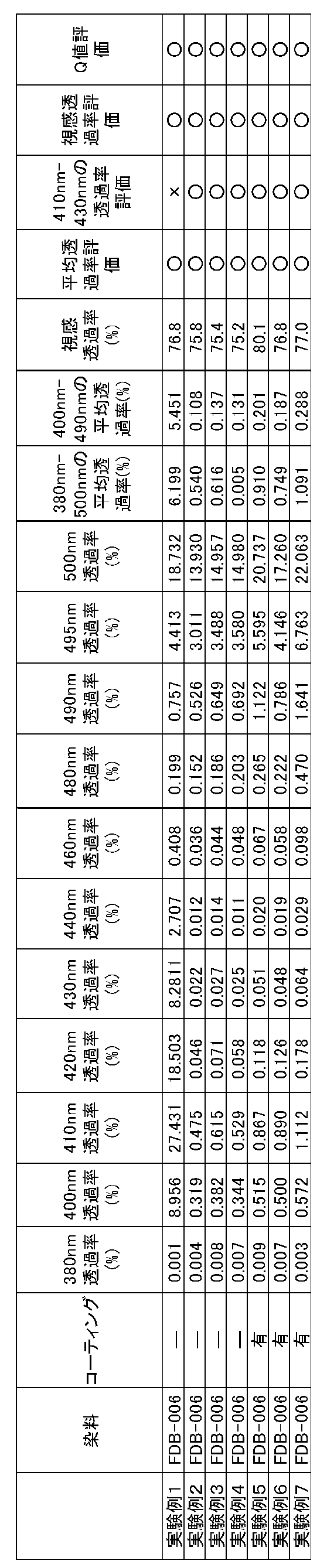
また、表1の実験例2~実験例7に示されるように、さらに、機能性染料とともに、黄色の昇華性染料を加えて染色を行うことによって、視感透過率が75%以上、且つ、青色領域の波長域における410nm~430nmの各波長の透過率が5%以下となる機能を樹脂体に付加することができることが確認できた。すなわち、黄色の染料を用いることで、黄色の染料を加えていない場合に、透過率が他の青色領域の波長域の透過率と比較して高めの透過率であった410nm~430nmの波長域における透過率についても、他の青色領域の波長域の透過率と同レベルまで透過率を低減させることができていることが確認できた。このため、この樹脂体は、青色領域の波長域内に波長のピークがある光であれば、ほぼ全波長について良好に透過率を低減させることができ、より効果的な樹脂体を取得することができることが示された。すなわち、この樹脂体は、青色領域のほぼ全領域の波長域において、波長のピークが異なる種々の光を照射した場合であっても、各光に対して良好に透過率を低減することができることが示された。
また、表1の実験例2~実験例7に示されるように、機能性染料とともに、黄色の昇華性染料を加えて染色を行うことによって、青色領域の特に380nm~495nmの波長域の光については、各波長の透過率を10%以下とすることができ、青色領域のほぼ全領域において、波長のピークが異なる種々の光を照射した場合であっても、各光に対して良好に透過率を低減することができることが示された。すなわち、380nm~495nmに波長域に波長のピークを持つ光であれば、より効果的に透過率を低減することができる。
また、表1の実験例2~実験例7に示されるように、機能性染料とともに、黄色の昇華性染料を加えて染色を行うことによって、380nm~500nmの青色領域の波長域における平均透過率も5%以下とでき、より効果的に透過率を低減することができる。また、表1の実験例2~実験例7に示されるように、400nm~490nmの波長域における平均透過率については1%以下とすることができ、より効果的に透過率を低減することができる。
また、表1の実験例3及び実験例4に示されるように、機能性染料及び黄色の昇華性染料とともに、赤色の昇華性染料、黄色の昇華性染料を加えて、染色を行うことによって、樹脂体の色を調整することができることが確認された。例えば、赤色の昇華性染料を加えた場合には、赤みかかった樹脂体を得ることができることが確認できた。また、青色の昇華性染料を加えた場合には、青みかかった樹脂体を得ることができることが確認できた。このように、例えば、機能を付加することができるとともに、任意の色を付加することができるため、容易に所望の色に染色した機能樹脂体を得ることができる。
また、表1の実験例5~実験例6に示されるように、MR8レンズに機能を付加するに加え、コーティング処理を行うことで、青色領域の波長域における透過率が高くなる領域が生じるものの、視感透過率をより向上させることができることが確認できた。なお、コーティング処理を行った場合であっても、青色領域の波長域における平均透過率は10%以下であり、機能が十分に付加されていることが確認できた。

また、表2の比較例2~7の実験例に示されるように、気相転写染色法にて、機能性染料の代わりに黄色の昇華性染料を用いた場合には、380nm~500nmの青色領域の波長域の光の平均透過率を10%以下とする機能を付加することができないことが確認された。コーティング処理を行った場合でも同様であった。
1 機能付加用基体
2 基体
8 レンズ
10 染料塗布装置
11 インクジェットプリンタ
12 パーソナルコンピュータ
13 インクカートリッジ
14 装着部
15 インクジェットヘッド
16 制御部
20 メモリ
30 蒸着装置
50 染料定着装置
100 製造システム
2 基体
8 レンズ
10 染料塗布装置
11 インクジェットプリンタ
12 パーソナルコンピュータ
13 インクカートリッジ
14 装着部
15 インクジェットヘッド
16 制御部
20 メモリ
30 蒸着装置
50 染料定着装置
100 製造システム
Claims (6)
- 樹脂体に対して青色領域の波長域の透過率を低減する機能樹脂体の製造方法であって、
青色領域の光の吸収を行うメロシアニン系の機能性染料であって、昇華性を有する機能性染料を、基体に塗布することで、機能付加用基体を取得する第1工程と、
前記第1工程によって取得された前記機能付加用基体を樹脂体と対向させ、前記機能付加用基体を加熱することによって、前記機能付加用基体に塗布された前記機能性染料を昇華させ、前記機能性染料を前記樹脂体に付着させる第2工程と、
前記第2工程によって、前記機能性染料が付着された前記樹脂体を加熱することによって、前記機能性染料を前記樹脂体に定着させる第3工程と、
を備え、
視感透過率が75%以上、且つ、青色領域の波長域における平均透過率が10%以下となる機能を前記樹脂体に付加することを特徴とする機能樹脂体の製造方法。 - 請求項1の機能樹脂体の製造方法において、
前記第1工程は、前記樹脂体を染色するための黄色の染料であって、昇華性を有する昇華性染料を、さらに塗布した前記機能付加用基体を取得し、
前記第2工程は、前記機能付加用基体に塗布された前記昇華性染料を昇華させ、前記昇華性染料を前記樹脂体に付着させ、
前記第3工程は、前記第2工程によって、前記昇華性染料が付着された前記樹脂体を加熱することによって、前記昇華性染料を前記樹脂体に定着させ、
視感透過率が75%以上、且つ、青色領域の波長域における410nm~430nmの各波長の透過率が5%以下となる機能を前記樹脂体に付加することを特徴とすることを特徴とする機能樹脂体の製造方法。 - 請求項1又は2の機能樹脂体の製造方法において、
前記昇華性染料は、さらに、赤色の染料と、青色の染料と、の少なくともいずれかを含むことを特徴とする機能樹脂体の製造方法。 - 請求項1~3のいずれかの機能樹脂体の製造方法において、
前記第1工程は、前記機能性染料が含有された染色用インクを印刷装置を用いて、前記基体に印刷することによって、前記機能付加用基体を取得することを特徴とする機能樹脂体の製造方法。 - 請求項1~4のいずれかの機能樹脂体の製造方法において、
前記第2工程は、前記第1工程によって取得された前記機能付加用基体を前記樹脂体と非接触に対向させ、前記機能付加用基体を加熱することによって、前記機能付加用基体に塗布された前記機能性染料を昇華させ、前記機能性染料を前記樹脂体に付着させることを特徴とする機能樹脂体の製造方法。 - 請求項1~5のいずれかの機能樹脂体の製造方法において、
前記樹脂体は、レンズであることを特徴とすることを特徴とする機能樹脂体の製造方法。
Priority Applications (1)
| Application Number | Priority Date | Filing Date | Title |
|---|---|---|---|
| JP2020536343A JP7306396B2 (ja) | 2018-08-10 | 2019-05-28 | 機能樹脂体の製造方法 |
Applications Claiming Priority (2)
| Application Number | Priority Date | Filing Date | Title |
|---|---|---|---|
| JP2018150983 | 2018-08-10 | ||
| JP2018-150983 | 2018-08-10 |
Publications (1)
| Publication Number | Publication Date |
|---|---|
| WO2020031469A1 true WO2020031469A1 (ja) | 2020-02-13 |
Family
ID=69415493
Family Applications (1)
| Application Number | Title | Priority Date | Filing Date |
|---|---|---|---|
| PCT/JP2019/021145 Ceased WO2020031469A1 (ja) | 2018-08-10 | 2019-05-28 | 機能樹脂体の製造方法 |
Country Status (2)
| Country | Link |
|---|---|
| JP (1) | JP7306396B2 (ja) |
| WO (1) | WO2020031469A1 (ja) |
Cited By (2)
| Publication number | Priority date | Publication date | Assignee | Title |
|---|---|---|---|---|
| WO2022163295A1 (ja) * | 2021-01-29 | 2022-08-04 | 株式会社ニデック | 染色システム |
| WO2025254231A1 (ko) * | 2024-06-04 | 2025-12-11 | 배석만 | 인시튜 형성 렌즈를 갖는 섬유사형 광 수송 매체 및 그 제조 방법 |
Citations (7)
| Publication number | Priority date | Publication date | Assignee | Title |
|---|---|---|---|---|
| JP2002258004A (ja) * | 2001-03-06 | 2002-09-11 | Nidek Co Ltd | プラスチックレンズの染色用インク及び該インクを用いたプラスチックレンズの染色方法。 |
| JP2004121435A (ja) * | 2002-09-30 | 2004-04-22 | Nidek Co Ltd | 眼内レンズの着色方法及び該方法にて得られる着色眼内レンズ |
| JP2011064954A (ja) * | 2009-09-17 | 2011-03-31 | Hoya Corp | 染色プラスチックレンズの製造方法 |
| JP2013205522A (ja) * | 2012-03-27 | 2013-10-07 | Hoya Corp | プラスチックレンズの昇華染色方法 |
| JP2015118122A (ja) * | 2013-12-16 | 2015-06-25 | 東海光学株式会社 | 眼鏡レンズ及び眼鏡 |
| JP2017502352A (ja) * | 2013-12-23 | 2017-01-19 | エシロル アンテルナショナル(コンパーニュ ジェネラル ドプテーク) | 無色外観を有する透明光学物品 |
| WO2017171075A1 (ja) * | 2016-03-31 | 2017-10-05 | ホヤ レンズ タイランド リミテッド | 眼鏡レンズおよび眼鏡 |
Family Cites Families (1)
| Publication number | Priority date | Publication date | Assignee | Title |
|---|---|---|---|---|
| US9813338B2 (en) * | 2015-12-10 | 2017-11-07 | Cisco Technology, Inc. | Co-existence of routable and non-routable RDMA solutions on the same network interface |
-
2019
- 2019-05-28 WO PCT/JP2019/021145 patent/WO2020031469A1/ja not_active Ceased
- 2019-05-28 JP JP2020536343A patent/JP7306396B2/ja active Active
Patent Citations (7)
| Publication number | Priority date | Publication date | Assignee | Title |
|---|---|---|---|---|
| JP2002258004A (ja) * | 2001-03-06 | 2002-09-11 | Nidek Co Ltd | プラスチックレンズの染色用インク及び該インクを用いたプラスチックレンズの染色方法。 |
| JP2004121435A (ja) * | 2002-09-30 | 2004-04-22 | Nidek Co Ltd | 眼内レンズの着色方法及び該方法にて得られる着色眼内レンズ |
| JP2011064954A (ja) * | 2009-09-17 | 2011-03-31 | Hoya Corp | 染色プラスチックレンズの製造方法 |
| JP2013205522A (ja) * | 2012-03-27 | 2013-10-07 | Hoya Corp | プラスチックレンズの昇華染色方法 |
| JP2015118122A (ja) * | 2013-12-16 | 2015-06-25 | 東海光学株式会社 | 眼鏡レンズ及び眼鏡 |
| JP2017502352A (ja) * | 2013-12-23 | 2017-01-19 | エシロル アンテルナショナル(コンパーニュ ジェネラル ドプテーク) | 無色外観を有する透明光学物品 |
| WO2017171075A1 (ja) * | 2016-03-31 | 2017-10-05 | ホヤ レンズ タイランド リミテッド | 眼鏡レンズおよび眼鏡 |
Cited By (4)
| Publication number | Priority date | Publication date | Assignee | Title |
|---|---|---|---|---|
| WO2022163295A1 (ja) * | 2021-01-29 | 2022-08-04 | 株式会社ニデック | 染色システム |
| JPWO2022163295A1 (ja) * | 2021-01-29 | 2022-08-04 | ||
| EP4286581A4 (en) * | 2021-01-29 | 2024-12-18 | Nidek Co., Ltd. | DYEING SYSTEM |
| WO2025254231A1 (ko) * | 2024-06-04 | 2025-12-11 | 배석만 | 인시튜 형성 렌즈를 갖는 섬유사형 광 수송 매체 및 그 제조 방법 |
Also Published As
| Publication number | Publication date |
|---|---|
| JPWO2020031469A1 (ja) | 2021-08-26 |
| JP7306396B2 (ja) | 2023-07-11 |
Similar Documents
| Publication | Publication Date | Title |
|---|---|---|
| JP2001214386A (ja) | プラスチックレンズの染色方法及び染色用基体 | |
| JP6999273B2 (ja) | 染色装置及び染色方法 | |
| JP7306396B2 (ja) | 機能樹脂体の製造方法 | |
| US20020148053A1 (en) | Method of dyeing a plastic lens, a plastic lens obtained by use of the dyeing method, and a dyeing system, a dyeing device, and a dyeing jig for a plastic lens | |
| JP4421176B2 (ja) | プラスチックレンズの染色方法、染色装置及び染色レンズ | |
| EP3461945B1 (en) | Dyeing method and manufacturing method of dyeing base body | |
| WO2002071108A1 (en) | Ink for dyeing plastic lens and method for dyeing plastic lens using the ink | |
| JP7404866B2 (ja) | 染色偏光レンズの製造方法 | |
| JP4365060B2 (ja) | プラスチックレンズ染色方法及び該方法に用いるプラスチックレンズ染色用インク | |
| JP2001159746A (ja) | プラスチックレンズ染色方法及び染色レンズ | |
| WO2019167388A1 (ja) | 機能付き染色樹脂体の製造方法 | |
| JP4268767B2 (ja) | プラスチックレンズの染色方法 | |
| EP3761081B1 (en) | Method for manufacturing multifunctional resin body | |
| US11623419B2 (en) | Method of producing photochromic resin body and method of producing function-adding base body | |
| JP6972848B2 (ja) | 染色方法及び染色用基体の製造方法 | |
| JP4068310B2 (ja) | 紫外線吸収効果を有するプラスチックレンズの製造方法及び該方法に使用する紫外線吸収用インク | |
| EP2868484B1 (en) | Dyeing base body, method for producing dyed resin body, and method for producing dyeing base body | |
| JP2004121434A (ja) | 眼内レンズの着色方法及び該方法にて得られる着色眼内レンズ | |
| JP6977452B2 (ja) | 印刷装置及びキャリア剤インクのインク容器 | |
| JP2019059205A (ja) | キャリア剤インク |
Legal Events
| Date | Code | Title | Description |
|---|---|---|---|
| 121 | Ep: the epo has been informed by wipo that ep was designated in this application |
Ref document number: 19847093 Country of ref document: EP Kind code of ref document: A1 |
|
| ENP | Entry into the national phase |
Ref document number: 2020536343 Country of ref document: JP Kind code of ref document: A |
|
| NENP | Non-entry into the national phase |
Ref country code: DE |
|
| 122 | Ep: pct application non-entry in european phase |
Ref document number: 19847093 Country of ref document: EP Kind code of ref document: A1 |