WO2020031411A1 - 流量測定装置、及び流量測定装置を適用した配管設備 - Google Patents
流量測定装置、及び流量測定装置を適用した配管設備 Download PDFInfo
- Publication number
- WO2020031411A1 WO2020031411A1 PCT/JP2019/009132 JP2019009132W WO2020031411A1 WO 2020031411 A1 WO2020031411 A1 WO 2020031411A1 JP 2019009132 W JP2019009132 W JP 2019009132W WO 2020031411 A1 WO2020031411 A1 WO 2020031411A1
- Authority
- WO
- WIPO (PCT)
- Prior art keywords
- flow
- flow path
- orifice
- fluid
- flow rate
- Prior art date
- Legal status (The legal status is an assumption and is not a legal conclusion. Google has not performed a legal analysis and makes no representation as to the accuracy of the status listed.)
- Ceased
Links
Images


Classifications
-
- G—PHYSICS
- G01—MEASURING; TESTING
- G01F—MEASURING VOLUME, VOLUME FLOW, MASS FLOW OR LIQUID LEVEL; METERING BY VOLUME
- G01F1/00—Measuring the volume flow or mass flow of fluid or fluent solid material wherein the fluid passes through a meter in a continuous flow
- G01F1/68—Measuring the volume flow or mass flow of fluid or fluent solid material wherein the fluid passes through a meter in a continuous flow by using thermal effects
- G01F1/684—Structural arrangements; Mounting of elements, e.g. in relation to fluid flow
- G01F1/6842—Structural arrangements; Mounting of elements, e.g. in relation to fluid flow with means for influencing the fluid flow
-
- F—MECHANICAL ENGINEERING; LIGHTING; HEATING; WEAPONS; BLASTING
- F15—FLUID-PRESSURE ACTUATORS; HYDRAULICS OR PNEUMATICS IN GENERAL
- F15D—FLUID DYNAMICS, i.e. METHODS OR MEANS FOR INFLUENCING THE FLOW OF GASES OR LIQUIDS
- F15D1/00—Influencing flow of fluids
- F15D1/001—Flow of fluid from conduits such as pipes, sleeves, tubes, with equal distribution of fluid flow over the evacuation surface
-
- F—MECHANICAL ENGINEERING; LIGHTING; HEATING; WEAPONS; BLASTING
- F15—FLUID-PRESSURE ACTUATORS; HYDRAULICS OR PNEUMATICS IN GENERAL
- F15D—FLUID DYNAMICS, i.e. METHODS OR MEANS FOR INFLUENCING THE FLOW OF GASES OR LIQUIDS
- F15D1/00—Influencing flow of fluids
- F15D1/02—Influencing flow of fluids in pipes or conduits
- F15D1/025—Influencing flow of fluids in pipes or conduits by means of orifice or throttle elements
-
- G—PHYSICS
- G01—MEASURING; TESTING
- G01F—MEASURING VOLUME, VOLUME FLOW, MASS FLOW OR LIQUID LEVEL; METERING BY VOLUME
- G01F1/00—Measuring the volume flow or mass flow of fluid or fluent solid material wherein the fluid passes through a meter in a continuous flow
- G01F1/05—Measuring the volume flow or mass flow of fluid or fluent solid material wherein the fluid passes through a meter in a continuous flow by using mechanical effects
- G01F1/34—Measuring the volume flow or mass flow of fluid or fluent solid material wherein the fluid passes through a meter in a continuous flow by using mechanical effects by measuring pressure or differential pressure
- G01F1/36—Measuring the volume flow or mass flow of fluid or fluent solid material wherein the fluid passes through a meter in a continuous flow by using mechanical effects by measuring pressure or differential pressure the pressure or differential pressure being created by the use of flow constriction
- G01F1/40—Details of construction of the flow constriction devices
-
- G—PHYSICS
- G01—MEASURING; TESTING
- G01F—MEASURING VOLUME, VOLUME FLOW, MASS FLOW OR LIQUID LEVEL; METERING BY VOLUME
- G01F1/00—Measuring the volume flow or mass flow of fluid or fluent solid material wherein the fluid passes through a meter in a continuous flow
- G01F1/05—Measuring the volume flow or mass flow of fluid or fluent solid material wherein the fluid passes through a meter in a continuous flow by using mechanical effects
- G01F1/34—Measuring the volume flow or mass flow of fluid or fluent solid material wherein the fluid passes through a meter in a continuous flow by using mechanical effects by measuring pressure or differential pressure
- G01F1/36—Measuring the volume flow or mass flow of fluid or fluent solid material wherein the fluid passes through a meter in a continuous flow by using mechanical effects by measuring pressure or differential pressure the pressure or differential pressure being created by the use of flow constriction
- G01F1/40—Details of construction of the flow constriction devices
- G01F1/42—Orifices or nozzles
Definitions
- the present invention relates to a flow measuring device.
- thermal flow sensor that includes a heating unit and a temperature detection unit and measures the flow rate of a fluid to be measured has been known (for example, Patent Document 1).
- a thermal flow sensor is disposed in a fluid flow path, measures fluid temperature at two points upstream and downstream of a heating unit, and calculates a flow rate based on a temperature difference between the two points.
- Patent Literature 1 has a flow measurement unit using the above-described thermal flow sensor, an inflow hole and an outflow hole of a fluid, and a rectification unit between the flow measurement unit and each of the inflow hole and the outflow hole.
- a honeycomb, a mesh, or the like is used as a rectification member disposed in the rectification unit.
- the rectifying portion in the case where a member such as a mesh or a honeycomb as described above is used for the rectifying portion, there is a problem that a pressure loss increases due to a resistance when the fluid passes through the member.
- the fluid in a configuration in which the rectifying unit is not provided, the fluid may be affected by the structure of the flow path, causing a drift, which may adversely affect the accuracy of the measured flow rate.
- the measurement target fluid contains dust, which adheres and accumulates inside the flow measurement device, particularly in the vicinity of the measurement site, which adversely affects the accuracy of the measurement value. there were.
- an object of the present invention is to provide a flow rate measurement device capable of reducing a pressure loss of a fluid and suppressing an adverse effect on a measured value due to disturbance such as drift, dust adhesion, and the like.
- a flow measurement device includes a main flow path through which a fluid to be measured flows, a flow rate measurement unit for measuring a flow rate of the fluid, and a flow rate measurement unit for measuring a fluid communicating with the main flow path.
- a flow path measuring device comprising an inlet and an outlet, and a sub-flow path arranged so that fluid flows from the intake through the inside of the flow measuring section to the outlet.
- An orifice portion disposed in the main flow path so as to be located between the intake port and the discharge port of the passage, wherein the orifice portion is at least higher than a central portion in a fluid flow direction.
- An orifice portion central flow passage tapered so that an upstream flow passage becomes narrower toward the central portion, and an opening communicating with the downstream side are arranged on an inner wall surface of the orifice portion central flow passage.
- At least the opening on the upstream side of the orifice portion side flow passage may be opened at a predetermined angle along the taper of the orifice portion center flow passage.
- the plurality of near-orifice passages may be arranged at equal intervals in a circumferential direction of an inner wall surface of the orifice center passage.
- at least one or more openings may be arranged at positions different from the one or more openings in the radial direction of the orifice section central channel.
- the fluid to be measured flows more smoothly, so that the effect of reducing pressure loss and suppressing drift due to disturbance can be further enhanced.
- the main flow path upstream of the orifice portion may be provided with a taper so that the flow path becomes narrower toward the orifice portion.
- a recess formed by the inner wall surface of the orifice center flow passage and the inner wall surface of the main flow passage may be provided at a boundary portion of the orifice portion and the main flow passage upstream of the orifice portion.
- the intake is located at a boundary portion of the main flow path upstream of the orifice portion and the orifice portion, the concave portion is a substantially triangular shape having the intake as a vertex, The apex angle of the substantially triangular shape having the intake at the apex may be 100 degrees or more and 120 degrees or less.
- the fluid to be measured that has flowed into the flow measurement device can be more efficiently guided to the orifice portion, and dust can be more effectively prevented from flowing into the flow measurement portion.
- the sub flow path may include a flow path in a direction perpendicular to the main flow path.
- the distance from the upstream open end of the main flow path to the orifice portion may be a straight pipe structure having a predetermined length or more.
- the straight pipe structure refers to a configuration having no bent portion. Since the fluid is naturally rectified while passing through the straight pipe structure, by having the straight pipe structure of a predetermined length, the effect of suppressing the drift due to the influence of disturbance can be enhanced.
- the piping equipment according to the present invention includes the above-mentioned flow rate measuring device. Further, in the piping equipment, a length of a straight pipe distance upstream from the orifice portion of the flow rate measuring device may be equal to or less than a second predetermined length.
- the straight pipe distance is a distance of a straight pipe structure having no bent portion. Since the fluid is naturally rectified while passing through the straight pipe structure, the longer the distance between the straight pipe structures, the more the influence of the drift can be reduced. Conversely, when the fluid flows through the bent portion, the flow is disturbed, causing a drift.
- the measurement sensitivity can be improved satisfactorily. Can be kept.
- a flow rate measuring device capable of reducing pressure loss of a fluid and suppressing an adverse effect on a measured value due to disturbance such as drift or dust adhesion.
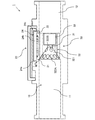
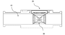
- FIG. 1 is a schematic cross-sectional view illustrating a configuration example of a flow measurement device according to an application example.
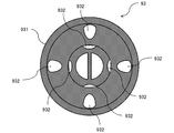
- FIG. 2 is a schematic diagram illustrating a state where an orifice portion of the flow measurement device according to the application example is viewed from the upstream main flow path side.
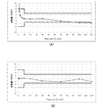
- FIG. 3A is a graph showing a relationship between an output error and a flow rate in a flow rate measuring device having a conventional structure.
- FIG. 3B is a graph showing a relationship between an output error and a flow rate in the flow measurement device according to the application example.
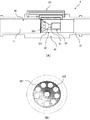
- FIG. 4A is a perspective view illustrating the flow measurement device according to the first embodiment.
- FIG. 4B is a perspective sectional view showing the internal configuration of the flow measurement device according to the first embodiment.
- FIG. 5 is a perspective view schematically showing the internal structure of the flow measurement device according to the first embodiment.
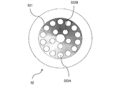
- FIG. 6 is a schematic diagram illustrating a state in which the upstream orifice portion of the flow measurement device according to the first embodiment is viewed from the upstream main flow path side.
- FIG. 7A is a perspective view schematically illustrating a flow measurement device according to a modification.
- FIG. 7B is a schematic diagram illustrating a state where the orifice portion of the flow measurement device according to the modification is viewed from the upstream main flow path side.
- FIG. 8 is a perspective view schematically showing another modification of the flow measurement device.
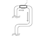
- FIG. 9 is a schematic diagram illustrating the piping equipment according to the second embodiment.
- FIG. 1 is a schematic sectional view showing a configuration example of a flow measurement device 9 according to this application example.
- hatched hatching indicates a cross section
- white arrows indicate the direction in which the fluid to be measured flows.
- the flow measurement device 9 has a tubular shape having a hollow portion in the longitudinal direction, and includes a main flow path portion 91, a sub flow path portion 92, and an orifice portion 93. You.
- the main flow path portion 91 is a tubular member penetrating in the longitudinal direction.
- the main flow path 91 has an upstream main flow path 911 upstream of the flow direction of the fluid to be measured and a downstream main flow path 912 downstream of the orifice 93.
- Both the upstream main flow channel portion 911 and the downstream main flow channel portion 912 have a structure in which the inner peripheral surface is tapered so that the flow channel becomes thinner toward the orifice portion 93.
- the axial length of the main flow path 91 is about 50 mm
- the diameter of the inner peripheral surface (the inner diameter of the main flow path 91) is about 20 mm
- the outer diameter of the main flow path 91 is about 24 mm.
- the sub flow path 92 includes an inlet 921 and an outlet 922 communicating with the main flow path 91, and a flow sensor 923.
- the sub flow path 920 is provided between the inlet 921 and the outlet 922. Is formed.
- the sub flow path 920 includes an intake flow path 920a, a flow rate measurement flow path 920b, and a discharge flow path 920c.
- a portion adjacent to the flow sensor 923 is used in the flow rate measurement flow path 920b. This corresponds to the flow measurement unit 920d.
- the flow sensor 923 can be configured to include a thermal flow sensor including a control unit, a heating unit, and a temperature detection unit.
- the intake channel 920a is a channel for allowing the fluid to be measured flowing through the main channel section 91 to flow in and diverting to the flow rate measurement channel 920b.
- the flow rate measurement flow path 920b is a flow path including the flow rate measurement unit 920d, and the flow rate of the fluid to be measured flowing through the flow path is measured by the flow sensor 923.
- the flow measurement flow channel 920 b includes a portion formed in a direction perpendicular to the main flow channel portion 91.
- the discharge channel 920c is a channel for discharging the measurement target fluid that has passed through the flow rate measurement channel 920b from the sub-channel portion 92 to the main channel portion 91.
- the orifice portion 93 is a cylindrical member disposed in the main flow passage portion 91 so as to be located between the intake port 921 and the discharge port 922. As shown in FIG. 1, an intake channel 920 a and a discharge channel 920 c are located on the outer peripheral side of the orifice portion 93. As shown in FIG. 1, the orifice section 93 includes an orifice section central flow path 931 tapered toward the center in the fluid flow direction, and a plurality of orifice section side flow paths 932.
- FIG. 2 is a schematic view showing a state where the orifice section 93 is viewed from the upstream main flow path section 911 side.
- four orifice section side flow paths are provided at equal intervals in the circumferential direction of the orifice section central flow path 931, and differ in the radial direction of the orifice section central flow path 931 and the fluid flow direction.
- Two rows are arranged at positions.
- a concave portion V formed by the inner wall surface of the orifice portion central flow passage 931 and the inner wall surface of the main flow passage portion 91 is formed immediately upstream of the orifice portion 93.
- the concave portion V is formed in a groove shape having an apex angle of 100 degrees to 120 degrees, for example.
- the configuration is such that the intake port 921 of the sub-channel portion 92 is disposed at a position located at the vertex of the concave portion V.
- the fluid to be measured that has flowed into the orifice portion 93 is divided into the orifice portion central flow channel 931 and each orifice portion side flow channel 932, passes through the orifice portion 93, and flows out to the downstream main flow channel portion 912.
- a part of the fluid to be measured that has flowed toward the intake port 921 of the sub flow path unit 92 is guided to the orifice section side flow path 932 by the concave portion V, and passes through the orifice section 93 to the downstream main flow path unit 912. leak.
- the fluid to be measured that has been diverted by the intake port 921 of the sub flow path portion 92 without flowing into the central portion of the orifice portion 93 flows into the intake flow channel 920a, and further flows into the flow measurement flow channel 920b. , And flows out to the downstream main flow path section 912 via the discharge flow path 920c.
- the flow rate is measured by a thermal flow sensor (not shown).
- the measured flow rate value may be output via the control unit or may be stored in a memory (not shown).
- Rectification by such a configuration can reduce pressure loss as compared with rectification using a member such as a mesh. Thereby, even when the flow rate of the fluid to be measured is low, the measurement sensitivity can be kept in a good state. That is, the flow measurement device 9 according to this application example can reduce the pressure loss of the fluid and can suppress the decrease in measurement sensitivity due to the influence of disturbance.
- the dust contained in the fluid to be measured is reduced in flow rate.
- the flow into the measurement flow channel 920b can be suppressed.
- dust flows into the flow rate measurement unit 920d specifically, the flow path including the flow rate measurement flow path 920b
- these dusts adhere and accumulate in the flow path, which adversely affects the accuracy of the measured value.
- Become. Therefore, good measurement sensitivity can be maintained by guiding the dust to the orifice portion 93 and suppressing the dust from being taken into the flow path for measurement 920b.
- even with a configuration including a portion where the flow measurement flow channel 920b is formed in a direction perpendicular to the main flow channel portion 91 it is possible to prevent dust from adhering and accumulating near the thermal flow sensor.
- FIG. 3 is a diagram comparing the measured values of the fluctuation amount (output error) of the output value between the flow measuring device having the conventional structure and the flow measuring device 9 according to this application example.
- FIG. 3A is a graph showing the relationship between the output error and the flow rate in the conventional flow rate measuring device
- FIG. 3B is a graph showing the relationship between the output error and the flow rate in the flow rate measuring device 9 according to this application example.
- the vertical axis of the graph indicates the variation of the output value
- the horizontal axis indicates the flow rate.
- the error at the time of the low flow rate is very large in the flow rate measuring device of the conventional structure, while the flow rate measuring device 9 according to the application example has almost no error even at the low flow rate. It turns out that it is a state.
- FIG. 4A is a perspective view illustrating an example of the flow measurement device 1 according to the present embodiment.
- FIG. 4B is a perspective sectional view showing the internal configuration of an example of the flow measurement device 1 according to the present embodiment.
- FIG. 5 is a perspective view illustrating an example of the flow measurement device 1.
- the flow measurement device 1 is incorporated in, for example, a gas meter, a combustion device, an internal combustion engine such as an automobile, a fuel cell, other industrial devices such as medical equipment, and an embedded device, and measures the amount of gas passing through a flow path. Note that the white arrow in FIG. 4B indicates the direction in which the fluid to be measured flows.
- the flow measurement device 1 according to the present embodiment includes a main flow path unit 10, a sub flow path unit 20, and an orifice unit 30.
- the main flow path 10 is a tubular member penetrating in the longitudinal direction.
- the main flow path section 10 has an upstream main flow path 11 on the upstream side and a downstream main flow path 12 on the downstream side with respect to the flow direction of the fluid to be measured, with the orifice section 30 interposed therebetween.
- the upstream main flow path 11 and the downstream main flow path 12 are not the same length in the longitudinal direction, and the upstream main flow path 11 has a longer distance than the downstream main flow path 12. As described above, by increasing the distance of the upstream main flow path 11, the influence of disturbance such as piping can be reduced.
- the axial length of the main flow path 10 is about 60 mm
- the diameter of the inner peripheral surface is about 20 mm
- the outer diameter of the main flow path 10 is about 24 mm
- the length of the main channel 11 is 30 mm, but is not limited to such an example.
- the sub flow path unit 20 includes an intake port 21 and an exhaust port 22 communicating with the main flow path unit 10, and a flow sensor 23.
- a sub flow path 24 is provided between the intake port 21 and the discharge port 22. Is formed.
- the sub flow path 24 includes an intake flow path 24a, a flow rate measurement flow path 24b, and a discharge flow path 24c.
- a portion adjacent to the flow sensor 23 is provided in the flow rate measurement flow path 24b. This corresponds to the flow measuring unit 24d.
- a desired publicly-known technique can be applied to the flow sensor 23, and for example, a configuration including a control unit and a thermal flow sensor including a heating unit and a temperature detection unit can be adopted.
- the intake flow path 24a is provided in a direction perpendicular to the main flow path section 10, and allows a measurement target fluid flowing through the upstream main flow path 11 to flow from an intake port 21 provided immediately upstream of the orifice section 30, This is a flow path for splitting the flow into the flow measurement flow path 24b.
- the flow measurement flow channel 24b is a flow channel including the flow measurement unit 24d, and the flow sensor 23 measures the flow rate of the measurement target fluid flowing through the flow channel.
- the discharge flow path 24c is a flow path for discharging the measurement target fluid that has passed through the flow rate measurement flow path 24b from the sub flow path unit 20 to the main flow path unit 10.
- the orifice section 30 is a member arranged in the main flow path section 10 so as to be located between the intake port 21 and the discharge port 22. As shown in FIG. 4, the orifice portion 30 has a configuration including an upstream orifice portion 32 and a downstream orifice portion 33 with a center portion 31 as a boundary.
- the upstream orifice portion 32 has an orifice portion central flow path 321 tapered toward the central portion 31.
- openings on the upstream side of the plurality of orifice side flow paths 322 are arranged.
- FIG. 6 is a schematic diagram showing a state in which the upstream orifice portion 32 is viewed from the upstream main flow path 11.
- the orifice section side flow path 322 has upstream openings at equal intervals in the circumferential direction of the orifice section center flow path 321, the radial direction of the orifice section center flow path 321, and fluid flow. Are arranged over two rows at different positions in the flow direction.
- the orifice part side flow path 322A arranged radially outside the orifice part center flow path 321 has a downstream opening provided at the downstream end of the orifice part 30.
- the downstream opening of the orifice section side flow path 322 ⁇ / b> B arranged radially inside the orifice section central flow path 321 is provided at the upstream end of the downstream orifice section 33.
- the length of the flow path is different between the orifice part flow path 322A and the orifice part flow path 322B.
- the downstream orifice portion 33 has a hollow cylindrical shape, and has a downstream end (a portion corresponding to one plane of the cylinder) downstream of the orifice portion central flow passage 321 and the orifice portion side flow passage 322B. Side openings are provided. On the other hand, the downstream end of the downstream orifice portion 33 is entirely an opening, and is configured to communicate with the downstream main flow path 12. Further, the orifice portion side flow path 322A is configured to pass through the inside of the cylindrical outer peripheral wall.
- the orifice section side flow paths 322 are arranged at equal intervals in the circumferential direction around the orifice section center flow path 321, and the fluid to be measured is rectified by passing through the orifice section 30.
- the measurement target fluid diverted to the orifice section side flow path 322 flows out of the downstream opening to the downstream main flow path 12, and is diverted to the measurement target fluid passing through the orifice section center flow path 321 and the orifice section flow path 322 ⁇ / b> B.
- the target fluid flows out to the downstream main flow path 12 via the downstream orifice section 33.
- the measurement target fluid divided into the orifice part center flow path 321 and the orifice part side flow path 322B is reduced in the distance passing through the narrow flow path as compared with the case where the fluid flows directly to the downstream main flow path 12. And the pressure loss can be reduced accordingly.
- the fluid to be measured that has been diverted by the intake port 21 of the sub flow path section 20 without flowing into the orifice section 30 flows into the intake flow path 24a, and further flows into the flow rate measurement flow path 24b and the discharge flow path 24b. It flows out to the downstream main flow path 12 via the flow path 24c.
- the flow rate is measured by a thermal flow sensor (not shown).
- the measured flow rate value may be output via the control unit or may be stored in a memory (not shown).
- the flow measuring device 1 In the flow measuring device 1 according to the present embodiment as described above, most of the fluid to be measured flows downstream via the orifice portion 30, and at this time, the orifice portion central flow path 321 and the large number of orifice portions The flow is rectified by the side flow path 322. For this reason, it is possible to suppress the dust from flowing into the sub flow path 24 and attaching thereto, thereby adversely affecting the measurement result. Further, it is possible to suppress the occurrence of the drift due to the influence of the piping structure and the like. In addition, by performing rectification using such a configuration, pressure loss can be reduced as compared with rectification using a member such as a mesh, and even when the measurement target fluid has a low flow rate, the measurement sensitivity is improved. Can be kept in condition.
- the configuration of the flow measurement device may be different from that of the first embodiment.
- another example of the flow measurement device will be described. Since the modified example has substantially the same configuration as that of the above-described first embodiment, the same components are denoted by the same reference numerals as those of the first embodiment, and detailed description is omitted.
- FIG. 7A is a perspective view schematically showing the flow measuring device 2 according to the present modification
- FIG. 7B is a schematic diagram when the orifice portion 30 of the flow measuring device 2 is viewed from the upstream main flow path 11 side.
- the number of the orifice section side flow paths 325 of the flow measurement device 2 according to the present modified example is smaller than that of the orifice section side flow path 322 according to the first embodiment, and the inner diameter per one is larger.
- It has a configuration. Specifically, only one row of the orifice part side flow path 325 is arranged at equal intervals in the circumferential direction of the orifice part center flow path 321. With such a configuration, the structure of the orifice portion 30 can be simplified, so that costs related to manufacturing and maintenance of the device can be reduced.
- FIG. 8 is a schematic diagram showing still another modified example of the flow measuring device.
- the orifice portion 30 may have a structure in which the upstream side and the downstream side are symmetrical about the central portion 31. Even with such a configuration, effects such as suppression of pressure loss (improvement of low flow rate sensitivity), improvement of drift resistance, and improvement of dust resistance can be obtained.
- FIG. 9 is a schematic diagram illustrating piping equipment in which the flow rate measuring device 1 is installed, and arrows in the figure indicate the flow direction of the fluid to be measured.
- the fluid flowing through the pipe is not particularly limited, and may be a gas such as oxygen, carbon dioxide, propane, or a liquid such as water, a chemical solution, or gasoline.
- the measurement target fluid flowing through the pipe flows from the upstream to the downstream via the flow measurement device 1, and the flow rate is measured when passing through the flow measurement device 1.
- the flow measuring device 1 is installed near the bent portion of the pipe, and the length of the straight pipe distance from the bent portion of the pipe to the orifice portion 30 of the flow measuring device 1 is, for example, 50 mm. It is. In such a case, the fluid to be measured flows into the flow measurement device 1 in a state where there is a drift generated at the bent portion of the pipe.
- the measurement sensitivity of the flow rate is reduced.
- the measurement target fluid flowing into the flow rate measuring device 1 is rectified by the configuration of the orifice portion 30, and thus the measurement by such a drift is performed. A decrease in sensitivity can be suppressed.
- the upstream side and the downstream side of the flow measuring device may have a symmetrical structure with respect to the center.
- One aspect of the present invention includes a main flow path (91) through which a fluid to be measured flows, a flow rate measuring unit (920d) for measuring a flow rate of the fluid, and a fluid intake port (920) communicating with the main flow path. 921) and a discharge port (922), and a sub-flow path (920) arranged so that fluid flows from the intake port to the discharge port via the inside of the flow rate measurement unit (920).
- the orifice portion central flow path (931) including a tapered portion having a larger diameter than the more downstream flow path, and the inner flow path of the orifice central flow path communicates with the downstream side.
- a plurality of orifices provided such that the openings are arranged Scan unit offshoot path and (932), and a.
Landscapes
- Engineering & Computer Science (AREA)
- Physics & Mathematics (AREA)
- Fluid Mechanics (AREA)
- Mechanical Engineering (AREA)
- General Engineering & Computer Science (AREA)
- Measuring Volume Flow (AREA)
- General Physics & Mathematics (AREA)
Abstract
本発明に係る流体測定装置は、測定対象の流体が流れる主流路と、前記流体の流量を測定するための流量測定部と、前記主流路に連通する流体の取込口及び排出口を備え、前記取込口から前記流量測定部内を経由して前記排出口へ流体が流れるように配置された副流路と、を有する流量測定装置であって、前記取込口と前記排出口との間に位置するように、前記主流路に配置されるオリフィス部をさらに有しており、前記オリフィス部は、流体の流れ方向のより上流側の流路がより下流側の流路よりも広い径を有するテーパー部を含むオリフィス部中央流路と、前記オリフィス部中央流路の内壁面に下流側と連通する開口部が配置されるようにして設けられる、複数のオリフィス部傍流路と、を備える。
Description
本発明は、流量測定装置に関する。
従来から、加熱部及び温度検出部を備え、測定対象流体の流量を測定する、いわゆる熱式フローセンサが知られている(例えば特許文献1)。このような熱式フローセンサは、流体の流路に配置され、加熱部の上流と下流の2点で流体温度を測定し、2点間の温度差に基づいて流量を算出する。
特許文献1には、上記のような熱式フローセンサを用いた流量計測部と、流体の流入孔及び流出孔と、流量計測部と流入孔、流出孔それぞれとの間に整流部と有し、流入側と流出側とが対称となるように構成された装置において、整流部に配置される整流部材としてハニカム、メッシュ等を用いることが記載されている。このような構成によって、流量計測装置に方向性がなくなり、流体の流れ方向にかかわらず、整流部より整流された流体の流量を計測することが可能になる。
しかしながら、整流部に上記のようなメッシュ、ハニカムなどの部材を用いる場合には、流体がこれを通過する際の抵抗によって圧力損失が大きくなってしまうという問題があった。一方、整流部を設けない構成では、流体が流路の構造による影響を受けて偏流が生じ、流量の測定値の正確性に悪影響を及ぼしてしまう場合があった。また、測定対象流体には塵埃が含まれており、これらが流量測定装置の内部、特に計測部位の近傍に付着、堆積することで、その影響によって測定値の正確性に悪影響が生じるという問題もあった。
上記のような実情に鑑みて、本発明は、流体の圧力損失を低減し、かつ、偏流、塵埃付着などの外乱の影響による測定値への悪影響を抑制できる流量測定装置を提供することを目的とする。
上記の課題を解決するため、本発明に係る流量測定装置は、測定対象の流体が流れる主流路と、前記流体の流量を測定するための流量測定部と、前記主流路に連通する流体の取込口及び排出口を備え、前記取込口から前記流量測定部内を経由して前記排出口へ流体が流れるように配置された副流路と、を有する流量測定装置であって、前記副流路の前記取込口と前記排出口との間に位置するように、前記主流路に配置されるオリフィス部をさらに有しており、前記オリフィス部は、少なくとも流体の流れ方向における中央部よりも上流側の流路が、該中央部に向けて細くなるようにテーパーが設けられたオリフィス部中央流路と、前記オリフィス部中央流路の内壁面に下流側と連通する開口部が配置されるようにして設けられる、複数のオリフィス部傍流路と、を備えている。
このようにすれば、測定対象流体の大部分はオリフィス部のテーパーによって中央部へ誘導され、測定対象流体に含まれる塵埃が流量測定部に流入することを抑制することができる。また、オリフィス部中央流路及び、複数のオリフィス部傍流路によって測定対象流体の流れが整流されるため、配管構造などに起因する外乱の影響を抑制することができる。また、このような構成によって整流することで、メッシュ等の部材を用いて整流するよりも、圧力損失を低減することができ、測定対象流体が低流量である場合にも測定感度を良好な状態に保つことができる。
また、前記オリフィス部傍流路の少なくとも上流側の開口は、前記オリフィス部中央流路のテーパーに沿うように所定の角度を有して開口していてもよい。このような構成であると、測定対象流体がオリフィス部傍流路に分流される際に流れが乱れることを抑制することができる。
また、前記複数のオリフィス部傍流路は、前記オリフィス部中央流路の内壁面の周方向において等間隔に配置されていてもよい。また、前記複数のオリフィス部傍流路は、少なくとも一以上の開口部が、他の一以上の開口部とは、前記オリフィス部中央流路の径方向における異なる位置に配置されていてもよい。
このような構成であれば、測定対象流体がよりスムーズに流れるため、圧力損失の低減と、外乱の影響による偏流の抑制の効果をさらに高めることができる。
また、前記オリフィス部よりも上流側の前記主流路には、前記オリフィス部に向かって流路が細くなるように、テーパーが設けられていてもよい。また、前記オリフィス部と前記オリフィス部よりも上流側の前記主流路の境界部分に、前記オリフィス部中央流路の内壁面と前記主流路の内壁面とで形成される凹部が設けられていてもよい。また、前記取込口は、前記オリフィス部と前記オリフィス部よりも上流側の前記主流路の境界部分に位置しており、前記凹部は前記取込口を頂点とする略三角形状であって、前記略三角形状における前記取込口を頂点とする頂角が100度以上かつ120度以下であってもよい。
このような構成により、流量測定装置に流入した測定対象流体を、より効率的にオリフィス部に誘導することができ、より効果的に塵埃が流量測定部へ流入すること抑制することができる。
また、前記副流路は、前記主流路に対して垂直な方向の流路を含んでいてもよい。このような構成により、塵埃が流量測定部へ流入して堆積することをさらに抑制することができる。
また、前記主流路の上流側開口端部から前記オリフィス部までの距離が、所定長さ以上の直管構造であってもよい。ここで、直管構造とは屈曲部がない構成のことである。流体は直管構造を通る間に自然と整流されるため、所定長さの直管構造を有することにより、外乱の影響による偏流を抑制する効果を、より高くすることができる。
また、本発明に係る配管設備は、上記の流量測定装置を備える。また、前記配管設備において、前記流量測定装置の前記オリフィス部から上流における直管距離の長さが、第2所定長さ以下であってもよい。
ここで、直管距離とは、屈曲部がない直管構造の距離のことである。流体は直管構造を通る間に自然と整流されるため、直管構造の距離を長く取れば取るだけ偏流の影響を低減させることができる。逆に言うと、流体は屈曲部を流れる際に流れが乱れ、偏流を生じることになる。この点、本発明に係る上記の各流量測定装置を適用すれば、配管設備において流量測定装置から上流部分の直管距離の長さを十分に取れない場合であっても、測定感度を良好に保つことができる。
なお、上記の手段は、技術的な矛盾が生じない限りにおいて、自由に組み合わせて実施することができる。
本発明によれば、流体の圧力損失を低減し、かつ、偏流、塵埃付着などの外乱の影響による測定値への悪影響を抑制できる流量測定装置を提供することができる。
以下、図面を参照して、本発明の実施形態の一例について説明する。
<適用例>
(適用例の構成)
本発明は例えば、図1に示すような流量測定装置として適用することができる。図1は本適用例に係る流量測定装置9の構成例を示す概略断面図である。なお、図1中の斜線のハッチングは断面を、白矢印は測定対象流体の流れる方向を表している。図1に示すように、流量測定装置9は長手方向に中空部を有する管状の形状を有しており、主流路部91、副流路部92と、オリフィス部93と、を含んで構成される。
(適用例の構成)
本発明は例えば、図1に示すような流量測定装置として適用することができる。図1は本適用例に係る流量測定装置9の構成例を示す概略断面図である。なお、図1中の斜線のハッチングは断面を、白矢印は測定対象流体の流れる方向を表している。図1に示すように、流量測定装置9は長手方向に中空部を有する管状の形状を有しており、主流路部91、副流路部92と、オリフィス部93と、を含んで構成される。
主流路部91は、長手方向に貫通した管状部材である。主流路部91は、オリフィス部93を挟んで、測定対象流体の流れ方向に対して上流側の上流主流路部911と、下流側の下流主流路部912が形成されている。上流主流路部911及び下流主流路部912ともに、その内周面はオリフィス部93に向けて流路が細くなるようにテーパーが設けられた構造となっている。なお、例えば主流路部91の軸方向の長さは約50mmであり、内周面の直径(主流路部91の内径)は約20mmであり、主流路部91の外径は約24mmであるが、このような例には限定されない。
副流路部92は、主流路部91に連通する取込口921及び排出口922と、フローセンサ923を備えており、取込口921と排出口922との間に、副流路920が形成されている。副流路920は、取込用流路920aと、流量測定用流路920bと、排出用流路920cとから構成されており、流量測定用流路920bにおいて、フローセンサ923と隣接する箇所が流量測定部920dに該当する。なお、フローセンサ923には、所望の公知技術を適用することができ、例えば制御部と、加熱部及び温度検出部を備える熱式フローセンサを含む構成とすることができる。
取込用流路920aは、主流路部91を流れる測定対象流体を流入させて、流量測定用流路920bに分流させるための流路である。流量測定用流路920bは流量測定部920dを含む流路であり、当該流路を流れる測定対象流体の流量がフローセンサ923によって測定される。図1に示すように、流量測定用流路920bは主流路部91と垂直な方向に形成される箇所を含んでいる。排出用流路920cは流量測定用流路920bを通過した測定対象流体を、副流路部92から主流路部91に排出させるための流路である。
オリフィス部93は、取込口921と排出口922との間に位置するように、主流路部91内に配置される円筒状の部材である。図1に示すように、オリフィス部93の外周側に、取込用流路920a及び排出用流路920cが位置する構成となっている。図1に示すように、オリフィス部93は、流体の流れ方向における中央部に向けてテーパーが設けられているオリフィス部中央流路931と、複数のオリフィス部傍流路932を備えている。
図2は、オリフィス部93を上流主流路部911側から見た状態を示す概略図である。図1及び図2に示すように、オリフィス部傍流路は、オリフィス部中央流路931の周方向に等間隔に4つ、かつ、オリフィス部中央流路931の径方向及び流体の流れ方向における異なる位置に2列分、配置されている。
また、オリフィス部93の直上流部分には、オリフィス部中央流路931の内壁面と、主流路部91の内壁面とで形成される凹部Vが形成されている。当該凹部Vは、例えば頂角が100度~120度の溝状に形成される。本適用例では、凹部Vの頂点に位置する箇所に副流路部92の取込口921が配置されている構成である。
(流体の流れ)
次に、上記で述べた流量測定装置9を用いて、測定対象流体の流量を計測する際の流体の流れについて説明する。測定対象流体の流れる配管構造に流量測定装置9を設置すると、測定対象流体は上流主流路部911から下流主流路部912に向けて流れる。この際、上流主流路部911及び、オリフィス部中央流路931に設けられたテーパーによって誘導されることで、測定対象流体の多くはオリフィス部93の中央部に向けて流れ込むことになる。オリフィス部93に流れ込んだ測定対象流体はオリフィス部中央流路931及び各オリフィス部傍流路932に分流されて、オリフィス部93を通過し、下流主流路部912へと流出する。また、副流路部92の取込口921に向かった測定対象流体の一部は、凹部Vによってオリフィス部傍流路932へと誘導され、オリフィス部93を経由して下流主流路部912へと流出する。
次に、上記で述べた流量測定装置9を用いて、測定対象流体の流量を計測する際の流体の流れについて説明する。測定対象流体の流れる配管構造に流量測定装置9を設置すると、測定対象流体は上流主流路部911から下流主流路部912に向けて流れる。この際、上流主流路部911及び、オリフィス部中央流路931に設けられたテーパーによって誘導されることで、測定対象流体の多くはオリフィス部93の中央部に向けて流れ込むことになる。オリフィス部93に流れ込んだ測定対象流体はオリフィス部中央流路931及び各オリフィス部傍流路932に分流されて、オリフィス部93を通過し、下流主流路部912へと流出する。また、副流路部92の取込口921に向かった測定対象流体の一部は、凹部Vによってオリフィス部傍流路932へと誘導され、オリフィス部93を経由して下流主流路部912へと流出する。
一方、オリフィス部93の中央部へと流れ込まずに副流路部92の取込口921によって分流された測定対象流体は、取込用流路920aへと流入し、さらに流量測定用流路920b、排出用流路920cを経由して下流主流路部912へと流出する。分流された測定対象流体が流量測定用流路920bを通過する際に、図示しない熱式フローセンサによって流量が測定される。測定された流量の値は制御部を介してアウトプットされてもよいし、メモリ(図示せず)に保存されてもよい。
以上述べた様な本適用例に係る流量測定装置9では、測定対象流体の大部分はオリフィス部93を経由して下流へと流れ、この際にオリフィス部中央流路931及び、複数のオリフィス部傍流路932によって整流されることになる。このため、配管構造などに起因する外乱の影響を抑制することができる。
また、このような構成によって整流することで、メッシュ等の部材を用いて整流するよりも、圧力損失を低減することができる。これによって、測定対象流体が低流量である場合にも、測定感度を良好な状態に保つことができる。即ち、本適用例に係る流量測定装置9は流体の圧力損失を低減し、かつ、外乱の影響による測定感度の低下を抑制することができる。
さらに、測定対象流体の多くが上流主流路部911とオリフィス部中央流路931に設けられたテーパー、及び、凹部Vによって、オリフィス部93誘導されるため、測定対象流体に含まれる塵埃が、流量測定用流路920bに流れ込むことを抑制することができる。流量測定部920d(具体的には流量測定用流路920bを含む流路)に、塵埃が流れ込むと、これらは流路に付着、堆積していき、測定値の正確性に悪影響を与える原因となる。このため、塵埃をオリフィス部93に誘導し、流量測定用流路920bに取り込まれることを抑制することで、良好な測定感度を維持することができる。なお、流量測定用流路920bが主流路部91と垂直な方向に形成される箇所を含む構成によっても、塵埃が熱式フローセンサの近傍に付着、堆積することを抑制することができる。
図3は、従来構造の流量測定措置と、本適用例に係る流量測定装置9とで出力値の変動量(出力誤差)の計測値を比較した図である。図3Aが従来構造の流量測定装置における出力誤差と流量との関係を示すグラフ、図3Bが本適用例に係る流量測定装置9における出力誤差と流量と関係をしめすグラフである。いずれもグラフの縦軸が出力値の変動量、横軸が流量を示している。各グラフに示すように、従来構造の流量測定装置では、低流量の際の誤差が非常に大きいのに対して、本適用例に係る流量測定装置9では低流量であっても誤差がほぼ無い状態であることが分かる。
<実施形態1>
以下に、この発明を実施するための形態の他の一例を、さらに説明する。ただし、この実施形態に記載されている構成部品の寸法、材質、形状、その相対配置などは、特に記載がない限りは、この発明の範囲をそれらのみに限定する趣旨のものではない。
以下に、この発明を実施するための形態の他の一例を、さらに説明する。ただし、この実施形態に記載されている構成部品の寸法、材質、形状、その相対配置などは、特に記載がない限りは、この発明の範囲をそれらのみに限定する趣旨のものではない。
(構成)
図4Aは、本実施形態に係る流量測定装置1の一例を示す斜視図である。図4Bは、本実施形態に係る流量測定装置1の一例の内部構成を示す斜視断面図である。図5は、流量測定装置1の一例を示す透視図である。流量測定装置1は、例えばガスメータや燃焼機器、自動車等の内燃機関、燃料電池、その他医療等の産業機器、組込機器に組み込まれ、流路を通過する気体の量を測定する。なお、図4Bの白矢印は、測定対象流体の流れる方向を示している。図4及び図5に示すように、本実施形態に係る流量測定装置1は、主流路部10と、副流路部20と、オリフィス部30とを備えている。
図4Aは、本実施形態に係る流量測定装置1の一例を示す斜視図である。図4Bは、本実施形態に係る流量測定装置1の一例の内部構成を示す斜視断面図である。図5は、流量測定装置1の一例を示す透視図である。流量測定装置1は、例えばガスメータや燃焼機器、自動車等の内燃機関、燃料電池、その他医療等の産業機器、組込機器に組み込まれ、流路を通過する気体の量を測定する。なお、図4Bの白矢印は、測定対象流体の流れる方向を示している。図4及び図5に示すように、本実施形態に係る流量測定装置1は、主流路部10と、副流路部20と、オリフィス部30とを備えている。
主流路部10は、長手方向に貫通した管状部材である。主流路部10は、オリフィス部30を挟んで、測定対象流体の流れ方向に対して上流側の上流主流路11と、下流側の下流主流路12が形成されている。上流主流路11と下流主流路12とは長手方向の長さが同じではなく、上流主流路11のほうが、下流主流路12よりも長い距離を有する構成となっている。このように、上流主流路11の距離を長く取ることで、配管などの外乱の影響を低減することができる。例えば主流路部10の軸方向の長さは約60mmであり、内周面の直径(主流路部10の内径)は約20mmであり、主流路部10の外径は約24mmであり、上流主流路11の長さは30mmであるが、このような例には限定されない。
副流路部20は、主流路部10に連通する取込口21及び排出口22と、フローセンサ23を備えており、取込口21と排出口22との間に、副流路24が形成されている。副流路24は、取込用流路24aと、流量測定用流路24bと、排出用流路24cとから構成されており、流量測定用流路24bにおいて、フローセンサ23と隣接する箇所が流量測定部24dに該当する。なお、フローセンサ23には、所望の公知技術を適用することができ、例えば制御部と、加熱部及び温度検出部を備える熱式フローセンサを含む構成とすることができる。
取込用流路24aは、主流路部10と垂直な方向に設けられ、オリフィス部30の直上流部に設けられた取込口21から上流主流路11を流れる測定対象流体を流入させて、流量測定用流路24bに分流させるための流路である。流量測定用流路24bは流量測定部24dを含む流路であり、当該流路を流れる測定対象流体の流量がフローセンサ23によって測定される。排出用流路24cは流量測定用流路24bを通過した測定対象流体を、副流路部20から主流路部10に排出するための流路である。
オリフィス部30は、取込口21と排出口22との間に位置するように、主流路部10内に配置される部材である。図4に示すように、オリフィス部30は、中央部31を境にして上流側オリフィス部32と、下流側オリフィス部33からなる構成となっている。上流側オリフィス部32は、中央部31に向けてテーパーが設けられているオリフィス部中央流路321を備えている。また、オリフィス部中央流路321の内壁面には、複数のオリフィス部傍流路322の上流側の開口が配置されている。
図6は、上流側オリフィス部32を上流主流路11から見た状態を示す概略図である。図5及び図6に示すように、オリフィス部傍流路322は、その上流側の開口がオリフィス部中央流路321の周方向に等間隔に、かつ、オリフィス部中央流路321の径方向及び流体の流れ方向における異なる位置に、2列に亘って配置される構成となっている。このうち、オリフィス部中央流路321の径方向外側に配置されるオリフィス部傍流路322Aは、下流側の開口がオリフィス部30の下流側の端部に設けられている。一方、オリフィス部中央流路321の径方向内側に配置されるオリフィス部傍流路322Bの下流側の開口は、下流側オリフィス部33の上流側の端部に設けられている。このため、オリフィス部傍流路322Aと、オリフィス部傍流路322Bとは、流路の長さが異なっている。
下流側オリフィス部33は、中空の円筒形状をしており、上流側の端部(円筒の一方の平面に該当する箇所)には、オリフィス部中央流路321及び、オリフィス部傍流路322Bの下流側の開口が設けられている。一方、下流側オリフィス部33の下流側の端部は全体が開口部であり、下流主流路12に連通する構成となっている。また、オリフィス部傍流路322Aが、円筒形状の外周壁内を通る構成となっている。
(流体の流れ)
次に、上記で述べた流量測定装置1を用いて、測定対象流体の流量を計測する際の流体の流れについて説明する。測定対象流体の流れる配管構造に流量測定装置1を設置すると、測定対象流体は上流主流路11から下流主流路12に向けて流れる。この際、測定対象流体の多くはオリフィス部30を通過して下流主流路12に流れ、測定対象流体の一部が副流路部20を経由して、下流主流路12へと流れる。
次に、上記で述べた流量測定装置1を用いて、測定対象流体の流量を計測する際の流体の流れについて説明する。測定対象流体の流れる配管構造に流量測定装置1を設置すると、測定対象流体は上流主流路11から下流主流路12に向けて流れる。この際、測定対象流体の多くはオリフィス部30を通過して下流主流路12に流れ、測定対象流体の一部が副流路部20を経由して、下流主流路12へと流れる。
測定対象流体の多くは、オリフィス部中央流路321に設けられたテーパーによって誘導され、オリフィス部30の中央部31に向けて流れ込むことになる。ただし、中央部31に向けて流れ込んだ測定対象流体が全てオリフィス部中央流路321を通過するのではなく、オリフィス部中央流路321の内壁に設けられた開口から、オリフィス部傍流路322A、及びオリフィス部へと分流される。オリフィス部傍流路322はオリフィス部中央流路321を中心として周方向に等間隔に配置されており、測定対象流体はオリフィス部30を通過することによって整流される。
オリフィス部傍流路322に分流された測定対象流体は下流側の開口から下流主流路12に流出し、オリフィス部中央流路321を通過した測定対象流体及びオリフィス部傍流路322Bへと分流された測定対象流体は、下流側オリフィス部33を経由して下流主流路12に流出する。このため、オリフィス部中央流路321及びオリフィス部傍流路322Bに分流された測定対象流体は、直接下流主流路12へと流出する場合に比べて、細い流路を通過する距離が短縮されることになり、その分の圧力損失を低減させることができる。
一方、オリフィス部30へと流れ込まずに副流路部20の取込口21によって分流された測定対象流体は、取込用流路24aへと流入し、さらに流量測定用流路24b、排出用流路24cを経由して下流主流路12へと流出する。分流された測定対象流体が流量測定用流路24bを通過する際に、図示しない熱式フローセンサによって流量が測定される。測定された流量の値は制御部を介してアウトプットされてもよいし、メモリ(図示せず)に保存されてもよい。
以上述べたような本実施形態に係る流量測定装置1では、測定対象流体の大部分はオリフィス部30を経由して下流へと流れ、この際にオリフィス部中央流路321及び、多数のオリフィス部傍流路322によって整流されることになる。このため、塵埃が副流路24へ流入し、付着することによって測定結果に悪影響を与えることを抑制することができる。また、配管構造などの影響によって偏流が発生することを抑制することができる。また、このような構成によって整流することで、メッシュ等の部材を用いて整流するよりも、圧力損失を低減することができ、測定対象流体が低流量である場合にも、測定感度を良好な状態に保つことができる。
<変形例1>
なお、流量測定装置の構成について、上記実施形態1とは異なる構成とすることも可能である。以下に、流量測定装置の他の例について説明する。なお、変形例は、上述の実施形態1と概ね同様の構成を有するため、同一の構成については実施形態1と同じ符号を用いて詳細な説明を省略する。
なお、流量測定装置の構成について、上記実施形態1とは異なる構成とすることも可能である。以下に、流量測定装置の他の例について説明する。なお、変形例は、上述の実施形態1と概ね同様の構成を有するため、同一の構成については実施形態1と同じ符号を用いて詳細な説明を省略する。
図7Aは、本変形例に係る流量測定装置2の概略を示す透視図、図7Bは流量測定装置2のオリフィス部30を上流主流路11側から見た場合の概略図である。図7A及び図7Bに示すように、本変形例に係る流量測定装置2のオリフィス部傍流路325は、実施形態1に係るオリフィス部傍流路322よりも数が少なく、1つあたりの内径が大きい構成となっている。具体的には、オリフィス部傍流路325は、オリフィス部中央流路321の周方向に等間隔に、一列のみ配置されている。このような構成であると、オリフィス部30の構造を簡素化できるため、装置の製造及びメンテナンス等に係るコストを低減することができる。
<変形例2>
図8は流量測定装置のさらに他の変形例を示す概略図である。図8に示すように、オリフィス部30を、中央部31を中心として上流側と下流側が対称な構造としてもよい。このような構成であっても、圧力損失の抑制(低流量感度の向上)、偏流耐性の向上、塵埃耐性の向上、といった効果を得ることができる。
図8は流量測定装置のさらに他の変形例を示す概略図である。図8に示すように、オリフィス部30を、中央部31を中心として上流側と下流側が対称な構造としてもよい。このような構成であっても、圧力損失の抑制(低流量感度の向上)、偏流耐性の向上、塵埃耐性の向上、といった効果を得ることができる。
<実施形態2>
次に、実施形態1の流量測定装置1を設置した配管設備について説明する。図9は、流量測定装置1を設置した配管設備を示す概略図であり、図中の矢印は測定対象流体の流れ方向を示している。配管を流れる流体は特に限定されず、酸素、二酸化炭素、プロパンなどの気体であってもよいし、水、薬液、ガソリン、などの液体であってもよい。配管を流れる測定対象流体は流量測定装置1を経由して上流から下流へと流れ、流量測定装置1を通過する際にその流量が測定される。
次に、実施形態1の流量測定装置1を設置した配管設備について説明する。図9は、流量測定装置1を設置した配管設備を示す概略図であり、図中の矢印は測定対象流体の流れ方向を示している。配管を流れる流体は特に限定されず、酸素、二酸化炭素、プロパンなどの気体であってもよいし、水、薬液、ガソリン、などの液体であってもよい。配管を流れる測定対象流体は流量測定装置1を経由して上流から下流へと流れ、流量測定装置1を通過する際にその流量が測定される。
図9に示すように、流量測定装置1は配管の屈曲部分の近傍に設置されており、配管の屈曲部分から、流量測定装置1のオリフィス部30までの直管距離の長さは、例えば50mmである。このような場合には、配管の屈曲部分で生じた偏流を有した状態で、測定対象流体が流量測定装置1に流入することになる。
測定対象流体に偏流が生じている状態では、流量の測定感度は低下するが、流量測定装置1に流入した測定対象流体は、オリフィス部30の構成によって整流されるため、このような偏流による測定感度の低下を抑制することができる。
<その他>
上記の各例の説明は、本発明を例示的に説明するものに過ぎず、本発明は上記の具体的な形態には限定されない。本発明は、その技術的思想の範囲内で種々の変形及び組み合わせが可能である。例えば、上記の各実施形態に係る流量測定装置の上流主流路11に、適用例に係る流量測定装置と同様のテーパーを形成してもよい。
上記の各例の説明は、本発明を例示的に説明するものに過ぎず、本発明は上記の具体的な形態には限定されない。本発明は、その技術的思想の範囲内で種々の変形及び組み合わせが可能である。例えば、上記の各実施形態に係る流量測定装置の上流主流路11に、適用例に係る流量測定装置と同様のテーパーを形成してもよい。
また、流量測定装置の上流側と下流側を、中央部を中心として対称な構造となるようにしてもよい。このような構成の流量測定装置であると、流体の流れ方向に関わらず配管設備に設置することが可能である。また、逆流する流体の流量も計測することが可能になる。
本発明の一の態様は、測定対象の流体が流れる主流路(91)と、前記流体の流量を測定するための流量測定部(920d)と、前記主流路に連通する流体の取込口(921)及び排出口(922)を備え、前記取込口から前記流量測定部内を経由して前記排出口へ流体が流れるように配置された副流路(920)と、を有する流量測定装置(9)であって、前記副流路の前記取込口と前記排出口との間に位置するように、前記主流路に配置されるオリフィス部(93)をさらに有しており、流体の流れ方向のより上流側の流路がより下流側の流路よりも広い径を有するテーパー部を含むオリフィス部中央流路(931)と、前記オリフィス部中央流路の内壁面に下流側と連通する開口部が配置されるようにして設けられる、複数のオリフィス部傍流路(932)と、を備えている。
1、2、9・・・流量測定装置
10、91・・・主流路部
11、911・・・上流主流路
12、912・・・下流主流路
20、92・・・副流路部
21、921・・・取込口
22、922・・・排出口
23、923・・・フローセンサ
24、920・・・副流路
30、93・・・オリフィス部
321、931・・・オリフィス部中央流路
322、932・・・オリフィス部傍流路
V・・・凹部
10、91・・・主流路部
11、911・・・上流主流路
12、912・・・下流主流路
20、92・・・副流路部
21、921・・・取込口
22、922・・・排出口
23、923・・・フローセンサ
24、920・・・副流路
30、93・・・オリフィス部
321、931・・・オリフィス部中央流路
322、932・・・オリフィス部傍流路
V・・・凹部
Claims (11)
- 測定対象の流体が流れる主流路と、
前記流体の流量を測定するための流量測定部と、前記主流路に連通する流体の取込口及び排出口を備え、前記取込口から前記流量測定部内を経由して前記排出口へ流体が流れるように配置された副流路と、を有する流量測定装置であって、
前記取込口と前記排出口との間に位置するように、前記主流路に配置されるオリフィス部をさらに有しており、
前記オリフィス部は、
流体の流れ方向のより上流側の流路がより下流側の流路よりも広い径を有するテーパー部を含むオリフィス部中央流路と、
前記オリフィス部中央流路の内壁面に下流側と連通する開口部が配置されるようにして設けられる、複数のオリフィス部傍流路と、を備えていることを特徴とする、流量測定装置。 - 前記オリフィス部傍流路の少なくとも上流側の開口は、前記オリフィス部中央流路のテーパーに沿うように所定の角度を有して開口していることを特徴とする、請求項1に記載の流量測定装置。
- 前記複数のオリフィス部傍流路は、前記オリフィス部中央流路の内壁面の周方向において等間隔に配置されていることを特徴とする、請求項1又は2のいずれか一項に記載の流量測定装置。
- 前記複数のオリフィス部傍流路は、少なくとも一以上の開口部が、他の一以上の開口部とは、前記オリフィス部中央流路の径方向における異なる位置に配置されていることを特徴とする、請求項1から3のいずれか一項に記載の流量測定装置。
- 前記オリフィス部よりも上流側の前記主流路には、前記オリフィス部に向かって流路が細くなるように、テーパーが設けられていることを特徴とする、請求項1から4のいずれか一項に記載の流量測定装置。
- 前記オリフィス部と前記オリフィス部よりも上流側の前記主流路の境界部分に、前記オリフィス部中央流路の内壁面と前記主流路の内壁面とで形成される凹部が設けられることを特徴とする、請求項1から5のいずれか一項に記載の流量測定装置。
- 前記取込口は、前記オリフィス部と前記オリフィス部よりも上流側の前記主流路の境界部分に位置しており、
前記凹部は前記取込口を頂点とする略三角形状であって、前記略三角形状の前記取込口を頂点とする頂角が100度以上かつ120度以下であることを特徴とする、請求項6に記載の流量測定装置。 - 前記副流路は、前記主流路に対して垂直な方向の流路を含む、ことを特徴とする請求項1から7のいずれか一項に記載の流量測定装置。
- 前記主流路の上流側開口端部から前記オリフィス部までの距離が、所定長さ以上の直管構造であることを特徴とする、請求項1から8のいずれか一項に記載の流量測定装置。
- 請求項1から9のいずれか一項に記載の流量測定装置を備える配管設備。
- 請求項1から8のいずれか一項に記載の流量測定装置を備える配管設備であって、
前記流量測定装置の前記オリフィス部より上流における直管距離の長さが、第2所定長さ以下であることを特徴とする配管設備。
Priority Applications (2)
| Application Number | Priority Date | Filing Date | Title |
|---|---|---|---|
| CN201980046095.1A CN112384764B (zh) | 2018-08-10 | 2019-03-07 | 流量测量装置以及适用流量测量装置的配管设备 |
| DE112019004033.2T DE112019004033B4 (de) | 2018-08-10 | 2019-03-07 | Durchflussmesser und rohrleitungsanlage mit durchflussmesser |
Applications Claiming Priority (2)
| Application Number | Priority Date | Filing Date | Title |
|---|---|---|---|
| JP2018-151370 | 2018-08-10 | ||
| JP2018151370A JP7087811B2 (ja) | 2018-08-10 | 2018-08-10 | 流量測定装置、及び流量測定装置を適用した配管設備 |
Publications (1)
| Publication Number | Publication Date |
|---|---|
| WO2020031411A1 true WO2020031411A1 (ja) | 2020-02-13 |
Family
ID=69415422
Family Applications (1)
| Application Number | Title | Priority Date | Filing Date |
|---|---|---|---|
| PCT/JP2019/009132 Ceased WO2020031411A1 (ja) | 2018-08-10 | 2019-03-07 | 流量測定装置、及び流量測定装置を適用した配管設備 |
Country Status (4)
| Country | Link |
|---|---|
| JP (1) | JP7087811B2 (ja) |
| CN (1) | CN112384764B (ja) |
| DE (1) | DE112019004033B4 (ja) |
| WO (1) | WO2020031411A1 (ja) |
Families Citing this family (1)
| Publication number | Priority date | Publication date | Assignee | Title |
|---|---|---|---|---|
| JP2023165043A (ja) * | 2020-09-25 | 2023-11-15 | 日立Astemo株式会社 | 物理量測定装置 |
Citations (5)
| Publication number | Priority date | Publication date | Assignee | Title |
|---|---|---|---|---|
| US20060207658A1 (en) * | 2005-03-16 | 2006-09-21 | Kohlmann Thomas S | Offset variable-orifice flow sensor |
| JP2008233073A (ja) * | 2007-02-19 | 2008-10-02 | Yamatake Corp | 流量計および流量制御装置 |
| JP2009287982A (ja) * | 2008-05-28 | 2009-12-10 | Smc Corp | フローセンサ |
| CN202885881U (zh) * | 2012-11-25 | 2013-04-17 | 威海市捷能能源科技有限公司 | 带锥形整流器的超声波流量计 |
| CN204255415U (zh) * | 2014-11-12 | 2015-04-08 | 中国石油天然气股份有限公司 | 一种锥形孔板式气液两相流量计 |
Family Cites Families (9)
| Publication number | Priority date | Publication date | Assignee | Title |
|---|---|---|---|---|
| JP3511959B2 (ja) | 1999-11-05 | 2004-03-29 | 松下電器産業株式会社 | 流入・流出対称型流量計 |
| DE102004005760B4 (de) | 2004-02-05 | 2007-05-31 | Festo Ag & Co. | Durchfluss-Messvorrichtung |
| JP5062106B2 (ja) * | 2008-09-01 | 2012-10-31 | オムロン株式会社 | 流量測定装置 |
| JP5272930B2 (ja) * | 2009-07-01 | 2013-08-28 | オムロン株式会社 | 流量測定装置 |
| JP5288294B2 (ja) * | 2011-01-14 | 2013-09-11 | 株式会社デンソー | 流量測定装置 |
| JP5801761B2 (ja) * | 2012-06-15 | 2015-10-28 | 日立オートモティブシステムズ株式会社 | 熱式流量計 |
| DE102012224049A1 (de) * | 2012-12-20 | 2014-06-26 | Robert Bosch Gmbh | Sensorvorrichtung zur Erfassung mindestens einer Strömungseigenschaft eines fluiden Mediums |
| JP2015068794A (ja) * | 2013-09-30 | 2015-04-13 | 日立オートモティブシステムズ株式会社 | 熱式流量計 |
| JP6355609B2 (ja) * | 2015-10-28 | 2018-07-11 | 日立オートモティブシステムズ株式会社 | 熱式流量計 |
-
2018
- 2018-08-10 JP JP2018151370A patent/JP7087811B2/ja active Active
-
2019
- 2019-03-07 DE DE112019004033.2T patent/DE112019004033B4/de active Active
- 2019-03-07 CN CN201980046095.1A patent/CN112384764B/zh active Active
- 2019-03-07 WO PCT/JP2019/009132 patent/WO2020031411A1/ja not_active Ceased
Patent Citations (5)
| Publication number | Priority date | Publication date | Assignee | Title |
|---|---|---|---|---|
| US20060207658A1 (en) * | 2005-03-16 | 2006-09-21 | Kohlmann Thomas S | Offset variable-orifice flow sensor |
| JP2008233073A (ja) * | 2007-02-19 | 2008-10-02 | Yamatake Corp | 流量計および流量制御装置 |
| JP2009287982A (ja) * | 2008-05-28 | 2009-12-10 | Smc Corp | フローセンサ |
| CN202885881U (zh) * | 2012-11-25 | 2013-04-17 | 威海市捷能能源科技有限公司 | 带锥形整流器的超声波流量计 |
| CN204255415U (zh) * | 2014-11-12 | 2015-04-08 | 中国石油天然气股份有限公司 | 一种锥形孔板式气液两相流量计 |
Also Published As
| Publication number | Publication date |
|---|---|
| CN112384764A (zh) | 2021-02-19 |
| DE112019004033T5 (de) | 2021-04-29 |
| CN112384764B (zh) | 2024-09-17 |
| DE112019004033B4 (de) | 2023-09-07 |
| JP2020026999A (ja) | 2020-02-20 |
| JP7087811B2 (ja) | 2022-06-21 |
Similar Documents
| Publication | Publication Date | Title |
|---|---|---|
| US10048097B2 (en) | Gas sensor | |
| US7886592B2 (en) | Flow sensor | |
| US8099954B2 (en) | Exhaust manifold | |
| US20100158758A1 (en) | Gas Sensor Assembly | |
| US10775357B2 (en) | Gas sensor | |
| CN104271913A (zh) | 用于测量废气中成分的仪器 | |
| US11422069B2 (en) | Sensor device | |
| KR102498947B1 (ko) | 배기 가스 센서, 특히 입자 센서 | |
| WO2004046659A1 (ja) | 流体検出装置 | |
| JP7239434B2 (ja) | ガスセンサ及び保護カバー | |
| JP6654416B2 (ja) | ガスセンサ | |
| KR19980079420A (ko) | 감열식 유량센서 | |
| EP2538060B1 (en) | Exhaust device | |
| JP7087811B2 (ja) | 流量測定装置、及び流量測定装置を適用した配管設備 | |
| WO2023074294A1 (ja) | 流路アダプター | |
| JP7465739B2 (ja) | ガスセンサ及び保護カバー | |
| JP2016109668A (ja) | ガスセンサ取付構造 | |
| CN112638515B (zh) | 用于气体分析器的线性化或校准的气体混合装置 | |
| US11371975B2 (en) | Gas sensor and protective cover | |
| JP6430916B2 (ja) | 排気状態検出装置 | |
| JP5669583B2 (ja) | 流量算出システム、集積型ガスパネル装置及びベースプレート | |
| US12467398B2 (en) | Exhaust gas sensor assembly | |
| JP2016011883A (ja) | ガスセンサ | |
| WO2015046169A1 (ja) | 排気管構造 | |
| JP2005140672A (ja) | 吸気ダクト装置 |
Legal Events
| Date | Code | Title | Description |
|---|---|---|---|
| 121 | Ep: the epo has been informed by wipo that ep was designated in this application |
Ref document number: 19847563 Country of ref document: EP Kind code of ref document: A1 |
|
| 122 | Ep: pct application non-entry in european phase |
Ref document number: 19847563 Country of ref document: EP Kind code of ref document: A1 |