WO2020026744A1 - スプール式切換弁におけるシール構造及びそのスプール式切換弁 - Google Patents
スプール式切換弁におけるシール構造及びそのスプール式切換弁 Download PDFInfo
- Publication number
- WO2020026744A1 WO2020026744A1 PCT/JP2019/027454 JP2019027454W WO2020026744A1 WO 2020026744 A1 WO2020026744 A1 WO 2020026744A1 JP 2019027454 W JP2019027454 W JP 2019027454W WO 2020026744 A1 WO2020026744 A1 WO 2020026744A1
- Authority
- WO
- WIPO (PCT)
- Prior art keywords
- packing
- spool
- seal structure
- seal
- ridge
- Prior art date
- Legal status (The legal status is an assumption and is not a legal conclusion. Google has not performed a legal analysis and makes no representation as to the accuracy of the status listed.)
- Ceased
Links
Images


Classifications
-
- F—MECHANICAL ENGINEERING; LIGHTING; HEATING; WEAPONS; BLASTING
- F16—ENGINEERING ELEMENTS AND UNITS; GENERAL MEASURES FOR PRODUCING AND MAINTAINING EFFECTIVE FUNCTIONING OF MACHINES OR INSTALLATIONS; THERMAL INSULATION IN GENERAL
- F16J—PISTONS; CYLINDERS; SEALINGS
- F16J15/00—Sealings
- F16J15/16—Sealings between relatively-moving surfaces
- F16J15/32—Sealings between relatively-moving surfaces with elastic sealings, e.g. O-rings
- F16J15/3204—Sealings between relatively-moving surfaces with elastic sealings, e.g. O-rings with at least one lip
- F16J15/3228—Sealings between relatively-moving surfaces with elastic sealings, e.g. O-rings with at least one lip formed by deforming a flat ring
-
- F—MECHANICAL ENGINEERING; LIGHTING; HEATING; WEAPONS; BLASTING
- F16—ENGINEERING ELEMENTS AND UNITS; GENERAL MEASURES FOR PRODUCING AND MAINTAINING EFFECTIVE FUNCTIONING OF MACHINES OR INSTALLATIONS; THERMAL INSULATION IN GENERAL
- F16J—PISTONS; CYLINDERS; SEALINGS
- F16J15/00—Sealings
- F16J15/16—Sealings between relatively-moving surfaces
- F16J15/32—Sealings between relatively-moving surfaces with elastic sealings, e.g. O-rings
- F16J15/3268—Mounting of sealing rings
-
- F—MECHANICAL ENGINEERING; LIGHTING; HEATING; WEAPONS; BLASTING
- F16—ENGINEERING ELEMENTS AND UNITS; GENERAL MEASURES FOR PRODUCING AND MAINTAINING EFFECTIVE FUNCTIONING OF MACHINES OR INSTALLATIONS; THERMAL INSULATION IN GENERAL
- F16J—PISTONS; CYLINDERS; SEALINGS
- F16J15/00—Sealings
- F16J15/16—Sealings between relatively-moving surfaces
- F16J15/164—Sealings between relatively-moving surfaces the sealing action depending on movements; pressure difference, temperature or presence of leaking fluid
-
- F—MECHANICAL ENGINEERING; LIGHTING; HEATING; WEAPONS; BLASTING
- F16—ENGINEERING ELEMENTS AND UNITS; GENERAL MEASURES FOR PRODUCING AND MAINTAINING EFFECTIVE FUNCTIONING OF MACHINES OR INSTALLATIONS; THERMAL INSULATION IN GENERAL
- F16J—PISTONS; CYLINDERS; SEALINGS
- F16J15/00—Sealings
- F16J15/44—Free-space packings
- F16J15/441—Free-space packings with floating ring
-
- F—MECHANICAL ENGINEERING; LIGHTING; HEATING; WEAPONS; BLASTING
- F16—ENGINEERING ELEMENTS AND UNITS; GENERAL MEASURES FOR PRODUCING AND MAINTAINING EFFECTIVE FUNCTIONING OF MACHINES OR INSTALLATIONS; THERMAL INSULATION IN GENERAL
- F16J—PISTONS; CYLINDERS; SEALINGS
- F16J15/00—Sealings
- F16J15/44—Free-space packings
- F16J15/447—Labyrinth packings
-
- F—MECHANICAL ENGINEERING; LIGHTING; HEATING; WEAPONS; BLASTING
- F16—ENGINEERING ELEMENTS AND UNITS; GENERAL MEASURES FOR PRODUCING AND MAINTAINING EFFECTIVE FUNCTIONING OF MACHINES OR INSTALLATIONS; THERMAL INSULATION IN GENERAL
- F16J—PISTONS; CYLINDERS; SEALINGS
- F16J15/00—Sealings
- F16J15/56—Other sealings for reciprocating rods
-
- F—MECHANICAL ENGINEERING; LIGHTING; HEATING; WEAPONS; BLASTING
- F16—ENGINEERING ELEMENTS AND UNITS; GENERAL MEASURES FOR PRODUCING AND MAINTAINING EFFECTIVE FUNCTIONING OF MACHINES OR INSTALLATIONS; THERMAL INSULATION IN GENERAL
- F16K—VALVES; TAPS; COCKS; ACTUATING-FLOATS; DEVICES FOR VENTING OR AERATING
- F16K11/00—Multiple-way valves, e.g. mixing valves; Pipe fittings incorporating such valves
- F16K11/02—Multiple-way valves, e.g. mixing valves; Pipe fittings incorporating such valves with all movable sealing faces moving as one unit
- F16K11/06—Multiple-way valves, e.g. mixing valves; Pipe fittings incorporating such valves with all movable sealing faces moving as one unit comprising only sliding valves, i.e. sliding closure elements
- F16K11/065—Multiple-way valves, e.g. mixing valves; Pipe fittings incorporating such valves with all movable sealing faces moving as one unit comprising only sliding valves, i.e. sliding closure elements with linearly sliding closure members
- F16K11/07—Multiple-way valves, e.g. mixing valves; Pipe fittings incorporating such valves with all movable sealing faces moving as one unit comprising only sliding valves, i.e. sliding closure elements with linearly sliding closure members with cylindrical slides
- F16K11/0712—Multiple-way valves, e.g. mixing valves; Pipe fittings incorporating such valves with all movable sealing faces moving as one unit comprising only sliding valves, i.e. sliding closure elements with linearly sliding closure members with cylindrical slides comprising particular spool-valve sealing means
Definitions
- the present invention has a seal structure between a land portion of the spool and a sliding surface of the spool hole in a spool type switching valve in which a spool is slidably housed in a spool hole, and the seal structure.
- the present invention relates to a spool type switching valve.
- Patent Document 1 discloses a spool type switching valve that has an exhaust port and that operates a spool as a valve body in a spool hole formed therein to switch a connection state between these ports. It is widely known in the art as disclosed.
- the air supply port, the output port, and the exhaust port communicate with the spool hole.
- the spool has a land portion (large diameter portion) as a valve portion and an annular portion as a flow passage portion.
- the concave portions (small diameter portions) are formed alternately in the axial direction.
- the spool is slid in the axial direction by a drive unit such as an electromagnetic pilot valve.
- a drive unit such as an electromagnetic pilot valve.
- annular flow channel recessed corresponding to each port and an annular slidable surface for sliding the land portion of the spool.
- the corresponding ports communicate with the respective groove bottoms of the flow channel grooves.
- annular packing made of rubber elastic material and sealing the gap between the sliding surface of the spool hole and the sliding surface is mounted on the sliding surface formed by the outer peripheral surface of the land portion. This prevents the compressed fluid from leaking between the sliding surface and the sliding surface.
- a technical problem of the present invention is to provide a seal between a spool and a spool hole in a spool type switching valve, which can realize a smoother operation of the spool and can extend the life of the packing. It is an object of the present invention to provide a structure and a spool type switching valve provided with such a seal structure.
- the present invention is a seal structure in a spool type switching valve, wherein the switching valve is formed to extend in an axial direction, and an air supply flow path, an output flow path, and an exhaust flow path are communicated.
- the spool has land portions having a sliding portion on the outer periphery around the axis and annular concave portions having an outer diameter smaller than the land portion alternately along the axial direction.
- annular flow grooves recessed respectively corresponding to the air supply flow path, the output flow path, and the exhaust flow path, and the land portion of the spool slides with the sliding portions facing each other.
- the annular sliding surface is formed alternately along the axial direction.
- Each of the flow passage grooves is connected to one of the flow passages corresponding thereto, and an annular concave groove which opens in the radial direction is provided around the axis of the sliding portion of the land portion.
- the inner peripheral base end of the packing made of rubber elastic material is accommodated in the concave groove, and the outer peripheral end of the packing projects from the opening edge of the concave groove.
- a first seal portion is provided at one end in the axial direction of the end portion of the packing, and a second seal portion is provided around the shaft at the other end, and is housed in the concave groove.
- the outer diameter of the first and second seal portions in the packing in the state is formed smaller than the inner diameter of the sliding surface of the spool hole, and the sliding portion of the land portion slides on the spool hole. Of the pair of spaces facing the surface and defined by the land in the spool hole.
- a side end of the packing on the space side to which the compressed fluid is supplied expands in a radial direction by elastic deformation due to the pressure of the compressed fluid.
- the seal portion of the first and second seal portions on the space side to which the compressed fluid is supplied narrows the gap formed between the first and second seal portions and the sliding surface of the spool hole.
- it is characterized in that it is configured to contact the sliding surface.
- the packing and the groove have a left-right symmetry in the axial direction in a cross section along the axis, and the groove has a base end of the packing in contact with the groove.
- the depth is formed to be half or more of the height from the base end to the tip of the packing. More preferably, in the concave groove, the bottom wall surface and the pair of side wall surfaces form an angle of 90 degrees or less.
- the maximum width of the base end of the packing housed in the groove is smaller than the minimum width between the pair of side walls in the groove.
- the base end of the packing may be fixed to the bottom wall surface of the concave groove by adhesion.
- the packing has a pair of side end faces which are parallel to each other and are opposed to each other at both ends in the axial direction.
- the packing has a tip end face facing the sliding surface at the tip end of the packing, and the first seal is provided at one axial end of the tip end face in the axial direction.
- the second seal portion is formed at the other end in the axial direction of the distal end surface.
- the first seal portion is formed by a first ridge projecting radially from the distal end surface, and the second seal portion is formed radially from the distal end surface. Formed by the second protruding ridge.
- the distance from the slid surface in the radial direction to the tip of the first ridge and the second ridge is formed to be equal to each other, and further, the tip surface of the packing is equal to the slid surface.
- the height is parallel to each other, and the height from the tip surface to the tip of the first ridge and the second ridge is equal to each other, and the first ridge and the second ridge are in the axial direction. Are spaced apart from each other.
- the first ridge and the second ridge may be formed in a wedge shape in which the width in the axial direction gradually narrows from the distal end surface toward the distal end, or may be formed in the distal end surface of the packing.
- a labyrinth projection that forms a labyrinth seal may be provided between the first ridge and the second ridge.
- annular constriction grooves communicating with the openings of the concave grooves may be respectively provided, but at this time, more preferably, the constriction grooves are formed by concave curved surfaces. Is formed.
- a spool-type switching valve provided with the seal structure, wherein the switching valve has a housing in which the spool hole is formed. On the outer surface, the air supply passage is formed, and an air supply port for supplying a compressed fluid by connecting to a fluid pressure source is formed. The output passage is formed, and the compressed fluid from the fluid pressure source is supplied to the outside. And an exhaust port for outputting to the fluid pressure device, and an exhaust port for forming the exhaust passage and discharging the exhaust gas from the fluid pressure device can be provided. .
- the outer diameter of the first and second seal portions in the packing housed in the concave groove of the land portion is formed smaller than the inner diameter of the sliding surface of the spool hole. ing.
- the sliding portion of the land portion faces the sliding surface of the spool hole, and the compressed fluid is supplied from the air supply passage to one of a pair of spaces defined by the land portion in the spool hole.
- the side end of the packing on the space side where the compressed fluid is supplied expands in the radial direction by elastic deformation due to the pressure of the compressed fluid, whereby the first and the second
- the seal portion of the two seal portions on the space side to which the compressed fluid is supplied narrows a gap formed between the spool hole and the sliding surface, or contacts the sliding surface.
- the state in which the operation of the spool is stopped without supplying the compressed fluid to the air supply flow path that is, the state in which the land portion of the spool stops with its sliding surface facing the sliding surface of the spool hole. Even if it is maintained for a long period of time, at this time, since each seal portion of the packing is in a non-contact state with the sliding surface of the spool hole, the packing made of a rubber elastic material may be permanently deformed or the spool hole may be deformed. It is possible to prevent physical deterioration or damage caused by sticking to the sliding surface or the like.
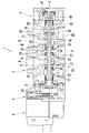
- FIG. 2 is a schematic cross-sectional view along an axis showing an embodiment of a spool type switching valve according to the present invention, showing a state where a spool is displaced to a first switching position.
- 1 shows a state in which the spool is displaced to a second switching position in the spool type switching valve of FIG.
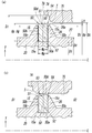
- It is a schematic sectional view showing a 1st embodiment of the seal structure concerning the present invention.
- FIG. 2A is an enlarged view of a portion M in FIG. 1 and shows a state in which a sliding portion of a land portion of a spool does not face a sliding surface of a spool hole.
- 2B is an enlarged view of a portion N in FIG.
- FIG. 2A is an enlarged view of a portion M in FIG. 1 and shows a state in which a sliding portion of a land portion of a spool does not face a sliding surface of a spool hole.
- 2B is an enlarged view of a portion N in FIG.
- FIG. 2A is an enlarged view of a portion M in FIG. 1 and shows a state in which a sliding portion of a land portion of a spool does not face a sliding surface of a spool hole.
- 2B is an enlarged view of a portion N in FIG.
- FIG. 11 is a schematic cross-sectional view illustrating a modified example of the seal structure according to the second embodiment of FIG. 4.
- the spool-type switching valve 1 includes a spool hole 7 extending in the direction of the axis L, an air supply passage 8, output passages 9 and 10, and exhaust passages 11 and 12 communicated with the spool hole 7. It has a spool 20 as a main valve slidably inserted in the axis L direction into the spool hole 7, and a valve drive unit 5 for operating the spool 20. By sliding the spool 20 in the spool hole 7, the connection state between the output flow paths 9, 10 and the air supply flow path 8 and the exhaust flow paths 11, 12 is switched.
- the air supply flow path 8 is for supplying a compressed fluid such as compressed air from a fluid pressure source (not shown) (not shown) to the spool hole 7, and the output flow paths 9 and 10 are This is for outputting the compressed fluid supplied to the spool hole 7 to various fluid pressure devices (not shown) such as a fluid pressure actuator (for example, a pneumatic cylinder) driven by the compressed fluid.
- the channels 11 and 12 are for exhausting the exhaust from the fluid pressure device to the outside such as the atmosphere.
- the spool type switching valve 1 is an electromagnetic valve (electromagnetic pilot type switching valve), A valve body 2 having a passage 8, output passages 9 and 10, exhaust passages 11 and 12, and a spool 20, and a first adapter portion 3 connected to both side end surfaces of the valve body 2 in the direction of the axis L. And a second adapter portion 4 and an electromagnetic pilot valve portion as the valve drive portion 5 connected to a side end surface of the first adapter portion 3 opposite to the valve body portion 2.
- electromagnetic valve electromagnetic pilot type switching valve
- the valve main body 2 has a housing 6 integrally formed into a substantially rectangular parallelepiped by resin or metal, and the spool hole 7 penetrates between both end surfaces along the longitudinal direction of the housing 6. .
- the output channels 9 and 10 are formed in the plane (upper surface) of the housing 6, and output ports A and B for connecting piping to the fluid pressure device are opened.
- the air supply passage 8 is formed, and the air supply port P for connecting the flow passage (or pipe) from the fluid pressure source,
- An exhaust port EA that forms exhaust channels 11 and 12 and that can connect a channel (or piping) for discharging exhaust returned from the fluid pressure device through output ports A and B to the outside. , EB have been established.
- the output ports A and B are the output ports A.
- the output ports A, B and the output communication paths 9a, 10a form the output channels 9, 10, which are communicated with the spool holes 7 through output communication paths 9a, 10a having a smaller flow area than B.
- the air supply port P is communicated with the spool hole 7 through an air supply communication passage 8a having a smaller flow sectional area than the air supply port P, and the air supply port P is connected to the air supply communication passage 8a. Thereby, the air supply passage 8 is formed.
- exhaust ports EA, EB are communicated with the spool hole 7 through exhaust communication passages 11a, 12a having a smaller flow sectional area than the exhaust ports EA, EB, and the exhaust ports EA, EB communicate with the exhaust ports EA, EB.
- the exhaust passages 11 and 12 are formed by the passages 11a and 12a.
- the spool-type switching valve 1 includes one air supply port P, a first output port A and a second output port B arranged in parallel in the longitudinal direction of the housing 6, and In the longitudinal direction of No. 6, there are provided five ports of a first exhaust port EA and a second exhaust port EB arranged on both sides of the air supply port P.
- the spool 20 is connected to the air supply port P to the second output port B and the first output port A to the second output port B at the same time.
- a first switching position (see FIG. 1) connected to one exhaust port EA, and the air supply port P is connected to the first output port A, and the second output port B is connected to the second exhaust port EB at the same time. It can be selectively moved with respect to two switching positions with a second switching position (see FIG. 2).
- the inner peripheral surface of the spool hole 7 extends from the opening on one side end surface to which the first adapter portion 3 is attached to the opening on the other side end surface to which the second adapter portion 4 is attached in the axis L direction.
- the moving surface 75, the fourth channel groove 76, the fourth slidable surface 77, the fifth channel groove 78, and the second support portion 7b are sequentially provided. It is formed in an annular shape with the center at the center. That is, on the inner peripheral surface of the spool hole 7, these slidable surfaces and the flow channel are alternately formed along the axis L.
- the inner diameters D0 of the first and second support portions 7a and 7b and the first to fourth slid surfaces 71, 73, 75 and 77 are equal to each other, and the first, third and third inner surfaces are formed.
- the inner diameters D1 of the bottom surfaces of the five flow grooves 70, 74, 78 are formed equal to each other, and the inner diameters D2 of the bottom surfaces of the second and fourth flow grooves 72, 76 are formed equal to each other.
- the inner diameter D1 is formed slightly larger than the inner diameter D2, and the inner diameters D1 and D2 of these flow grooves are smaller than the inner diameter D0 of the sliding surface or the like within a range smaller than the width dimension of the housing 6. It is formed large.
- first pressed portion 20a and the other end (second pressed portion 20b) of the spool 20 are formed by the first support portion 7a and the second support portion 7b formed of the inner peripheral surface of the spool hole 7. ) Are supported in an airtight and slidable manner.
- the communication path 11a of the first exhaust flow path 11 is connected to the groove bottom of the first flow path groove 70, and the communication path 9a of the first output flow path 9 is connected to the groove bottom of the second flow path groove 72.
- the communication passage 8a of the air supply flow passage 8 is connected to the groove bottom surface of the third flow passage groove 74, and the communication passage 10a of the second output flow passage 10 is connected to the groove bottom surface of the fourth flow passage groove 76.
- the communication path 12a of the second exhaust flow path 12 communicates with the bottom of the fifth flow path groove 78.
- Reference numeral 79 in the drawing is used to supply a pilot fluid to the first adapter unit 3 or the second adapter unit 4 via the valve drive unit 5 through a pilot flow path (not shown).
- the pilot fluid supply hole is always in communication with the air supply passage 8.
- the spool 20 is airtightly and slidably fitted to the first support part 7a from one end on the first adapter part 3 side to the other end on the second adapter part 4 side in the axis L direction.
- a fourth land portion 28, a fifth annular concave portion 29, and a second pressed portion 20 b which is fitted in the second support portion 7 b in an airtight and slidable manner.
- Each of them is formed in an annular shape about the axis L. That is, in the spool 20, these annular concave portions and land portions are alternately formed along the axis L.
- each of the lands 22, 24, 26, and 28 has a gradually increasing width in the axis L direction in the radial direction Y from the base end connected to the adjacent annular concave portion to the sliding portion at the outer peripheral end.
- the lands are formed in a substantially equilateral trapezoidal shape that narrows, and these lands are symmetric in the direction of the axis L with respect to the center axis in the radial direction.
- annular grooves 15 are formed at the outer peripheral ends of the lands 22, 24, 26, and 28, annular grooves 15 (see FIGS. 3 to 6) are formed.
- An annular packing 50 which will be described in detail later, is mounted in each of the concave grooves 15 formed at the outer peripheral ends of the lands 22, 24, 26, and 28, respectively.
- the sliding portion of the land portion is A gap formed between the hole 7 and the sliding surface is sealed with the packing 50 so that leakage of the compressed fluid through the gap can be suppressed or prevented as much as possible.
- the seal member such as the packing 50
- the outer diameters D3 of the first and second pressed portions 20a and 20b and the first to fourth land portions 22, 24, 26 and 28 are equal to each other.
- the first to fifth annular recesses 21, 23, 25, 27, and 29 have the same outer diameter D4, and the outer diameter D3 is greater than the inner diameter D0 of the sliding surface or the like. Is slightly smaller and larger than the outer diameter D4.
- the first adapter portion 3 is formed to have a larger diameter than the spool hole 7 and opens to the valve body portion 2 side.
- the first adapter portion 3 is airtight to the cylinder hole 30 and slidable in the axis L direction.
- the first piston 31 fitted on the shaft L. That is, the cylinder hole 30 is air-tightly partitioned by the piston 31 into a first chamber 30 a closer to the valve drive unit 5 than the piston 31 and a second chamber 30 b closer to the valve body 2.
- the first piston 31 integrally has a first pressing portion 31a coaxially disposed with the spool 20 on the valve body 2 side, and the first pressing portion 31a is provided with the spool hole.
- the first chamber 30a is connected to a pilot valve of the valve drive unit 5, and the second chamber 30b is always open to the atmosphere.
- Reference numeral 32 in the drawing denotes a manual operation unit for pushing in by manual operation from the outside to exhaust the compressed fluid filled in the first chamber 30a.
- the second adapter portion 4 is formed with a larger diameter than the spool hole 7 and a smaller diameter than the first cylinder hole 30, and has a second cylinder hole 40 opened to the valve body 2 side;
- a second piston 41 fitted on the shaft L in an airtight manner and slidably in the direction of the axis L is provided on the shaft L. That is, the cylinder hole 40 is airtightly partitioned by the piston 41 into a first chamber 40a closer to the valve body 2 than the piston 41 and a second chamber 40b opposite to the first chamber 40a.
- the diameter of the first piston 31 is larger than the diameter of the second piston 41, and the pressure receiving area of the first piston 31 on the first chamber 30a side is the pressure receiving area of the second piston 41 on the second chamber 40b side. Is bigger than.
- the second piston 41 integrally has a second pressing portion 41a coaxially arranged with the spool 20 on the valve body 2 side, and the second pressing portion 41a is The diameter of the second support portion 7b is smaller than that of the second support portion 7b, and the second support portion 7b is in contact with the second pressed portion 20b of the spool 20.
- the first chamber 40a of the second cylinder hole 40 is communicated with the second chamber 30b of the first cylinder hole 30 through a through hole 20c penetrating the center of the spool 20 in the axis L direction. It is always open to the public.
- the second chamber 40b is always in communication with the pilot fluid supply hole 79, and is constantly pressurized by the pilot fluid. Therefore, the spool 20 is constantly pressed toward the first adapter portion 3 (ie, the first piston side) in the axis L direction.
- the pistons 31 and 41 may have not only a circular shape but also an elliptical shape or a track shape in a cross section orthogonal to the axis L. Therefore, in the present application, for the sake of convenience, a string that is circularly arranged around the axis L in this manner is referred to as a “diameter”, and the chord that crosses the axis L at right angles is uniformly referred to as “diameter”, and the distance from the axis L to the outer circumference is uniformly determined. It is referred to as "radius".
- the operation of the spool type switching valve 1 will be described with reference to FIGS.
- the first chamber 30 a of the first cylinder hole 30 is open to the atmosphere. Therefore, the second piston 41 moves the first piston 31 together with the spool 20 to the stroke end on the first chamber 30a side by the pressing force, and as a result, the spool 20 is moved to the first switching position.
- the state is switched.
- the first land portion 22 of the spool 20 is disposed at the position of the first flow channel 70 of the spool hole 7, and the second land portion 24 is positioned at the position of the second sliding surface 73.
- the third land portion 26 is disposed at the position of the third channel groove 74, and the fourth land portion 28 is disposed at the position of the fourth slidable surface 77.
- the connection between the first output flow path 9 including the first output port A and the air supply flow path 8 including the air supply port P is cut off by the second land portion 24, and
- the connection between the second output flow path 10 including the second output port B and the second exhaust flow path 12 including the second exhaust port EB is interrupted by the fourth land portion 28. Due to such a positional relationship between the spool hole 7 and the spool 20, the first output flow path 9 and the first exhaust flow path 11 are connected to each other through the spool hole 7, and the second output flow path
- the air supply passage 10 and the air supply passage 8 are similarly connected to each other through the spool hole 7. At this time, the second exhaust passage 12 is closed in the spool hole 7.
- the electromagnetic pilot valve part constituting the valve driving part 5 when the electromagnetic pilot valve part constituting the valve driving part 5 is ON, the pilot fluid is supplied to the first chamber 30 a of the first cylinder hole 30 through the valve driving part 5. Is done. Therefore, the first piston 31 causes the second piston 41 together with the spool 20 to move toward the stroke end of the second cylinder hole 40 on the second chamber 40b side against the pressing force of the second piston 41 due to the pressing force. As a result, the spool 20 is switched to the second switching position.
- the first land portion 22 of the spool 20 is disposed at the position of the first slidable surface 71 of the spool hole 7, and the second land portion 24 is positioned at the position of the third passage groove 74.
- the third land portion 26 is disposed at the position of the third slidable surface 75, and the fourth land portion 28 is disposed at the position of the fifth channel groove 78.
- the connection between the first output channel 9 including the first output port A and the first exhaust channel 11 including the first exhaust port EA is interrupted by the first land portion 22.
- the connection between the second output flow path 10 including the second output port B and the air supply flow path 8 including the air supply port P is interrupted by the third land portion 26. Due to such a positional relationship between the spool hole 7 and the spool 20, the first output flow path 9 and the air supply flow path 8 are connected to each other through the spool hole 7, and the second output flow path 10
- the second exhaust passage 12 is similarly connected to the second exhaust passage 12 through the spool hole 7. At this time, the first exhaust passage 11 is closed in the spool hole 7.
- the outer peripheral surface 26a of the land portion 26 of the spool 20 as the sliding portion is substantially parallel to the sliding surface 75.
- the concave groove 15 which opens in the radial direction Y is provided around the axis L, and the packing 50 is mounted in the concave groove 15.
- the material of the packing 50 is not particularly limited as long as it is a rubber elastic material exhibiting a sealing function.
- nitrile rubber, fluorine rubber, or the like can be used.
- the concave groove 15 is provided annularly around the axis L and extends flat along the axis L, and a radial direction Y (from the axis L and the axis L) extends from both ends of the bottom wall 15a in the axis L direction.
- the concave groove 15 is formed in a transverse cross section along the axis L in a rectangular shape symmetrical in the direction of the axis L with respect to the central axis extending in the radial direction Y.
- the concave groove 15 has a uniform depth Hg over the entire circumferential direction of the land 26.
- the groove width Wg of the concave groove 15 along the axis L is also formed uniformly over the entire depth from the opening to the bottom wall surface 15a.
- the concave groove 15 is not limited to the above-described embodiment.
- the pair of side wall surfaces 15b and 15c are made to intersect the bottom wall surface 15a and the outer peripheral surface 26a at an acute angle so that the groove width Wg is smaller than the above-described width. It may be formed in a substantially equilateral trapezoidal shape that gradually narrows from the wall surface 15a toward the opening.
- the packing 50 has an inner diameter smaller than the diameter D5 of the bottom wall surface 15a of the groove 15 when not used in the groove 15 when not used.
- the circumferential length of the inner circumferential surface (that is, the base end surface) 50 a of the packing 50 is formed shorter than the circumferential length of the bottom wall surface 15 a of the concave groove 15. Therefore, as shown in FIGS. 3 to 6, when the packing 50 is mounted in the concave groove 15, the packing 50 made of a rubber elastic material is extended in the circumferential direction, and the inner circumferential surface 50 a of the packing 50 is attached to the bottom wall surface 15 a. It is elastically pressed. Thereby, the sealing property between the inner peripheral surface 50a of the packing 50 and the bottom wall surface 15a of the concave groove 15 is ensured.
- the packing 50 has a substantially rectangular shape in a transverse cross section along the axis L, which is substantially bilaterally symmetric with respect to the central axis in the radial direction Y in the axis L direction. Is formed. That is, the outer shape of the packing 50 is defined by the base end surface 50 a formed by the inner peripheral surface of the packing 50, forming an annular shape around the axis L, and extending flat along the axis L, and the outer peripheral surface of the packing 50.
- a leading end face 50d that is formed and forms an annular shape around the axis L and extends flat along the axis L is connected to one end of the base end face 50a and the leading end face 50d in the axis L direction.
- a first side end face 50b extending in the radial direction Y facing the one side wall face 15b is connected to the other end of the base end face 50a and the front end face 50d in the axis L direction, and a second side wall face 15c of the concave groove 15 is formed.
- a second side end surface 50c extending in the radial direction Y in opposition to the second side end surface 50c.
- the entire surface of the base end surface 50a is pressed against the bottom wall surface 15a, and the base end surface 50a faces in parallel with the front end surface 50d.
- the pair of side end surfaces 50b and 50c are both formed in a plane as a whole, are parallel to each other and face rearward, and are perpendicular to the base end surface 50a and the front end surface 50d.
- the outer diameter of the packing 50 mounted in the concave groove 15 (the diameter of the distal end face 50d in the first embodiment) is Dp
- the outer diameter of the packing 50 starts from the base end face 50a pressed against the bottom wall surface 15a.
- a base end portion 52 of the height Hg is housed in the concave groove 15. At this time, it is preferable that the depth Hg of the groove 15 be equal to or more than 1 / of the height Hp of the entire packing 50, since the packing 50 can be prevented from coming off the groove 15.
- the packing 50 has a uniform width Wp in the axis L direction from the base end face 50a to the tip end face 50d in the radial direction Y, and the width Wp Is formed smaller than the width Wg of the concave groove 15. That is, in the present invention, the maximum width Wpmax of the base end portion 52 accommodated in the concave groove 15 of the packing 50 is formed smaller than the minimum width Wgmin of the concave groove 15. Therefore, the packing 50 is movable in the direction of the axis L between the first side wall surface 15b and the second side wall surface 15c of the concave groove 15 by the fluid pressure.
- the outer diameter Dp of the tip end face 50d of the packing 50 is slightly smaller than the inner diameter D0 of the sliding surface 75 of the spool hole 7.
- the end on the first side end surface 50b side of the end portion 51 of the packing 50 forms an annular first seal portion 53 around the axis L, and the end on the second side end surface 50c side is similarly formed.
- An annular second seal portion 54 is formed around the axis L.
- the first seal portion 53 includes a right-angled corner where the distal end surface 50d and the first side end surface 50b intersect.
- the second seal portion 54 includes the distal end surface 50d and the second side end surface. 50c is included.
- the sliding portions of the lands 22, 24, 26, 28 face the corresponding sliding surfaces 71, 73, 75, 77 in the spool hole 7, and the lands in the spool hole 7.
- the compressed fluid is supplied from the air supply passage 8 to one of a pair of spaces S1 and S2 (see FIGS. 3B to 5B) defined by the portions 22, 24, 26, and 28.
- the packing 50 is elastically deformed by the fluid pressure of the compressed fluid so that a necessary sealing property is secured between the sliding portion of the land and the sliding surface of the spool hole. Has become.
- the packing 50 is located on one of the first and second seal portions 53 and 54 on the side of one of the spaces S1 and S2 to which the compressed fluid is supplied.
- the spool 20 moves from the first switching position to the second switching position shown in FIG. 2, and accordingly, the land 26 and its packing 50 also move as described above. It moves from the position of FIG. 3 (a) to the position of FIG. 3 (b).
- the sliding portion 26a of the land 26 faces the sliding surface 75 of the spool hole 7, that is, the spool 26 is mounted on the land 26.
- the entire tip surface 50d of the packing 50 including the seal portions 53 and 54 faces the sliding surface 75, and the space in the spool hole 7 is connected to the air supply passage 8 by the land portion 26.
- the packing pressure moves by the fluid pressure in the concave groove 15 toward the second side wall surface 15c.
- the second side end surface 50c of the packing 50 is pressed against the second side wall surface 15c.
- the fluid pressure causes a clockwise moment in the drawing around the opening edge of the second side wall surface 15c to act on the packing 50, and the first side end face 50b of the packing 50.
- the side end of the first space S1 including the first seal portion 53 elastically extends in the radial direction Y (ie, toward the sliding surface 75 of the spool hole 7).
- the first seal portion 53 (especially, the corner portion) narrows the gap ⁇ formed between the first seal portion 53 and the sliding surface 75 or comes into contact with the sliding surface 75. Has become.
- leakage of the compressed fluid from the first space S1 to the second space S2 can be suppressed as much as possible, and the sealing property between these spaces S1 and S2 can be secured. I have.
- the packing 50 of the land 26 slides on the flow channel 74 of the spool hole 7. It moves across the boundary with the moving surface 75 (that is, the tapered portion T of the opening edge of the flow channel groove 74) to a position facing the sliding surface 75.
- the second seal portion 54 of the packing 50 faces the slidable surface 75, and then the first seal portion 53 also faces the slidable surface 75. Is formed smaller than the inner diameter D0 of the slidable surface 75 of the spool hole 7, so that at least the second seal portion 54 moves to a position facing the slidable surface 75 without colliding with the boundary portion.
- the packing 50 is pressed by the fluid pressure of the compressed fluid before the first seal portion 53 crosses the boundary portion (taper portion T). Is pressed against the second side wall surface 15c of the groove 15, and the side end of the packing 50 including the first side end surface 50b and the first seal portion 53 is deformed by elastic deformation. It is assumed that it extends in the direction Y.
- the outer diameter of the first seal portion (particularly, a right-angled corner where the front end face 50d and the first side end face 50b intersect) is larger than the inner diameter D0 of the sliding surface 75, Even if the first seal portion 53 collides with the boundary portion and further rides on the slidable surface 75 and makes contact therewith, the amount of deformation of the packing 50 associated therewith is smaller than that of the conventional one, and Since the force acting on the packing 50 accompanying them acts in a direction to restore the elastic deformation due to the fluid pressure, the load on the packing 50 due to the collision and the gap between the packing 50 and the sliding surface 75 are reduced. Can be suppressed as much as possible.
- the spool 20 is selectively displaced between the first switching position and the second switching position, so that the spools 8, 9, 10, 11, and 12 are displaced.
- the packing edges of the land portions 22, 24, 26, 28 are elastically deformed by the fluid pressure of the compressed fluid, so that the opening edges (tapered portions) of the flow passage grooves 70, 74, 78 Even if it collides with the part T), the load on the packing 50 can be suppressed as much as possible, and the frictional resistance generated between the packing 50 and the sliding surfaces 71, 73, 75, 77 can be reduced. Can be suppressed as much as possible.
- the operation of the spool 20 is stopped without supplying the compressed fluid to the air supply flow path 8, that is, the land portion of the spool 20 has its sliding surface facing the sliding surface of the spool hole 7. Even if the stopped state is maintained for a long period of time, the seals 53 and 54 of the packing 50 are not in contact with the sliding surface of the spool hole 7 at that time, so the packing made of rubber elastic material is used. 50 can be prevented from being physically deformed or damaged due to permanent deformation or sticking to the sliding surface of the spool hole 7. Further, when assembling the spool-type switching valve, it is not always necessary to perform a process (for example, chamfering) for introducing the spool 20 into the opening of the spool hole 7 in the housing 6.
- a process for example, chamfering
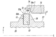
- the difference between the seal structure of the second embodiment and the seal structure of the first embodiment is mainly in the form of the first and second seal portions provided around the distal end portion 51 of the packing.
- the first seal portion is integrally formed in the radial direction Y from the end of the tip end surface 50d of the packing 50A on the first end face 50b side. It is formed by a projecting annular first ridge 53a.
- the second seal portion is formed by an annular second ridge 54a integrally protruding in the radial direction Y from an end of the distal end surface 50d on the second side end surface 50c side. That is, the protrusions 53a and 54a are spaced apart from both ends of the front end face 50d with a flat end face 50d interposed therebetween in the axis L direction.
- the packing 50A having the first ridges 53a and the second ridges 54a is also symmetrical in the transverse direction along the axis L with respect to the central axis in the radial direction Y in the axis L direction. Therefore, the distance from the tip surface 50d to the tip of each of the protrusions 53a, 54a is equal to each other, and the distance ⁇ from the slidable surface 75 of the cylinder hole 7 to the tip of each of the protrusions 53a, 54a. Are also equal to each other.
- the distance from the axis L to the tips of the ridges 53a and 54a is the outer diameter Dp of the packing 50A in the second embodiment.
- the pair of ridges 53a, 54a is formed by a wedge whose width in the direction of the axis L gradually decreases from the base end on the tip end surface 50d to the tip end on the sliding surface 75 side. It is formed in a shape.
- the first ridge 53a is composed of the first side end face 50b and an outer wall which is perpendicular to the tip end face 50d, and is erected from the tip end face 50d toward the first side end face 50b. Formed by the inner wall.
- the second ridge 54a is composed of the second side end face 50c and an outer wall perpendicular to the tip end face 50d, and an inner wall erected from the tip end face 50d toward the second side end face 50c.
- the packing 50A of the second embodiment has the same shape as the packing 50 of the first embodiment, except that a groove having an inverted isosceles trapezoidal cross-section having a bottom surface at the tip end surface 50d is formed at the center of the outer peripheral surface in the axis L direction.
- the tips of the first and second ridges 53a, 54a are formed by corners forming an acute angle with the first and second side end surfaces 50b, 50c.
- the first side end face 50b and the second side end face 50c of the packing 50B have annular shapes having the same diameter about the axis L.
- a first constriction groove 55a and a second constriction groove 55b are provided around. That is, the constriction grooves 55a and 55b are opposed to each other at the same height from the base end face 50a in the cross section of the packing 50B, and thereby the constricted portion where the width Wp of the packing 50B is narrowed. 56 are formed.
- the packing 50B when the fluid pressure in the first space S1 acts on the first side end face 50b by the constricted grooves 55a and 55b, for example, as shown in FIG. Elongation in the radial direction Y by elastic deformation is promoted.
- the packing 50B is also formed symmetrically in the direction of the axis L with respect to the center axis of the transverse section.
- the pair of constricted grooves 55a and 55b are formed by smooth concave curved surfaces, preferably circular arc surfaces, and the width of the constricted portion 56 is smaller than ⁇ ⁇ of the total width Wp of the packing 50B.
- the opening width of both constricted grooves 55a and 55b in the side end surfaces 50b and 50c is smaller than 1/2 of the total height Hp of the packing 50B.
- the whole of the pair of constricted grooves 55a and 55b and the constricted portion 56 are provided at the base end portion 52 of the packing 50B, and specifically, in the height direction of the packing 50B. Is formed on the outer peripheral side with respect to the center of the groove 15 and near the opening in the concave groove 15.
- the spool 20 is moved from the first switching position (see FIG. 1) to the second switching position (see FIG. 1). (See FIG. 2), the fluid pressure in the first space S1 exerts a clockwise moment force on the packing 50B in the figure. Then, as in the case of the first embodiment, the side end of the packing 50B on the first space S1 side (that is, the first side end face 50b side on which the fluid pressure of the compressed fluid is acting) extends.
- the first constriction groove 55a formed on the first side end face 50b expands due to the fluid pressure, but the second constriction groove 55b formed on the second side end face 50c, which is opposite thereto, contracts.
- the extension of the side end on the first side end face 50b side is further promoted.
- a gap is formed between the second side end face 50c and the second side wall face 15c of the concave groove 15, the extension of the side end on the first side end face 50b side is not hindered.
- the packing 50B is fixed to the center in the width direction of the groove 15 by bonding, the base end surface (inner peripheral surface) 50a of the packing 50B rises from the bottom wall surface 15a of the groove 15 by the moment force and the fluid pressure. Can be prevented.
- the first ridge 53a on the distal end face 50d of the packing 50A is used.
- a labyrinth protrusion 57 may be provided upright in the radial direction Y at a position between the second protrusion 54a and the second protrusion 54a.
- the labyrinth projection 57 is preferably formed in an annular shape around the axis L at the center of the tip end face 50d in the direction of the axis L (on the center axis of the cross section of the packing 50A) in parallel with the ridges 53a and 54a. Is formed.
- the cross-section is formed in a wedge shape, such as an isosceles triangle having an acute apex angle, which is bilaterally symmetric and gradually narrows toward the tip. It is desirable that the height of the labyrinth projection 57 from the distal end face 50d to the distal end be equal to or greater than the height of the ridges 53a, 54a.
- the seal structure of the spool-type switching valve according to the present invention has been described above.
- the present invention is not limited to the above embodiments, and various design changes may be made without departing from the scope of the claims. It goes without saying that it is possible.
- the base end surface 50a of the packing 50 and the bottom wall surface 15a of the concave groove 15 are bonded or the like as in the third embodiment of FIG. May be fixed.
- the valve drive unit 5 for operating the spool 20 is not limited to the one configured by the electromagnetic pilot valve unit, but may be configured by various drive mechanisms such as a direct drive type.
- the number of ports and the number of lands may be changed, or a coil spring may be used instead of the second piston 41.
- the seal portions 53 (53a) and 54 (54a) desirably have corners that form a right angle or an acute angle with the side end surfaces 50b and 50c of the packing 50, but are not necessarily limited thereto. It is not something to be done.
Landscapes
- Engineering & Computer Science (AREA)
- General Engineering & Computer Science (AREA)
- Mechanical Engineering (AREA)
- Multiple-Way Valves (AREA)
- Sealing Using Fluids, Sealing Without Contact, And Removal Of Oil (AREA)
- Sealing Devices (AREA)
- Sliding Valves (AREA)
Priority Applications (6)
| Application Number | Priority Date | Filing Date | Title |
|---|---|---|---|
| US17/262,473 US12025228B2 (en) | 2018-08-02 | 2019-07-11 | Seal structure for spool-type switching valve, and said spool-type switching valve |
| CN201980051083.8A CN112513503B (zh) | 2018-08-02 | 2019-07-11 | 滑阀式切换阀中的密封构造及该滑阀式切换阀 |
| MX2021001119A MX2021001119A (es) | 2018-08-02 | 2019-07-11 | Estructura de sellado para valvula de conmutacion de tipo carrete y dicha valvula de conmutacion de tipo carrete. |
| BR112021001745-3A BR112021001745A2 (pt) | 2018-08-02 | 2019-07-11 | estrutura de vedação para válvula de comutação tipo carretel e a dita válvula de comutação tipo carretel |
| EP19844607.2A EP3805617A4 (en) | 2018-08-02 | 2019-07-11 | SEAL STRUCTURE FOR COIL-TYPE SWITCH VALVE AND SAID COIL-TYPE SWITCH VALVE |
| KR1020217001171A KR102686566B1 (ko) | 2018-08-02 | 2019-07-11 | 스풀식 스위칭 밸브에 있어서의 시일 구조 및 그 스풀식 스위칭 밸브 |
Applications Claiming Priority (2)
| Application Number | Priority Date | Filing Date | Title |
|---|---|---|---|
| JP2018146327A JP7137161B2 (ja) | 2018-08-02 | 2018-08-02 | スプール式切換弁におけるシール構造及びそのスプール式切換弁 |
| JP2018-146327 | 2018-08-02 |
Publications (1)
| Publication Number | Publication Date |
|---|---|
| WO2020026744A1 true WO2020026744A1 (ja) | 2020-02-06 |
Family
ID=69230633
Family Applications (1)
| Application Number | Title | Priority Date | Filing Date |
|---|---|---|---|
| PCT/JP2019/027454 Ceased WO2020026744A1 (ja) | 2018-08-02 | 2019-07-11 | スプール式切換弁におけるシール構造及びそのスプール式切換弁 |
Country Status (9)
| Country | Link |
|---|---|
| US (1) | US12025228B2 (https=) |
| EP (1) | EP3805617A4 (https=) |
| JP (1) | JP7137161B2 (https=) |
| KR (1) | KR102686566B1 (https=) |
| CN (1) | CN112513503B (https=) |
| BR (1) | BR112021001745A2 (https=) |
| MX (1) | MX2021001119A (https=) |
| TW (1) | TWI805801B (https=) |
| WO (1) | WO2020026744A1 (https=) |
Cited By (1)
| Publication number | Priority date | Publication date | Assignee | Title |
|---|---|---|---|---|
| CN116642034A (zh) * | 2023-05-16 | 2023-08-25 | 安徽美芝精密制造有限公司 | 阀芯、多通阀、热管理系统和车辆 |
Citations (5)
| Publication number | Priority date | Publication date | Assignee | Title |
|---|---|---|---|---|
| JPS49112059A (https=) * | 1973-02-09 | 1974-10-25 | ||
| JP2010014202A (ja) * | 2008-07-03 | 2010-01-21 | Nok Corp | 密封装置 |
| JP2010101341A (ja) | 2008-10-21 | 2010-05-06 | Smc Corp | 低摺動パッキンを備えた流体圧機器 |
| WO2012124534A1 (ja) * | 2011-03-11 | 2012-09-20 | Nok株式会社 | 密封装置 |
| US20180080564A1 (en) * | 2016-09-22 | 2018-03-22 | Douglas E. Tanner | Self-Retaining, Easily Removable Pneumatic Seal |
Family Cites Families (9)
| Publication number | Priority date | Publication date | Assignee | Title |
|---|---|---|---|---|
| DE7105705U (de) * | 1971-02-16 | 1971-08-05 | Praedifa Jaeger Kg | Dichtungsring aus elastischem Werkstoff |
| JP3778623B2 (ja) * | 1996-07-29 | 2006-05-24 | Smc株式会社 | 逆流防止弁付き切換弁 |
| JPH10267141A (ja) * | 1997-03-21 | 1998-10-09 | Smc Corp | スプール |
| JP4763500B2 (ja) * | 2006-03-31 | 2011-08-31 | シーケーディ株式会社 | パイロット式切換弁 |
| JP4783917B2 (ja) * | 2009-04-13 | 2011-09-28 | Smc株式会社 | 4・5ポート切換弁 |
| JP5256545B2 (ja) | 2010-02-10 | 2013-08-07 | Smc株式会社 | 減圧切換弁 |
| US9625042B2 (en) * | 2012-10-08 | 2017-04-18 | First Sales Llc | Fluid additive control valve |
| JP5938839B2 (ja) * | 2014-02-10 | 2016-06-22 | Smc株式会社 | 電磁パイロット式スプール弁 |
| CN106979362B (zh) * | 2017-04-21 | 2023-02-03 | 浙江亿日气动科技有限公司 | 自动补偿气压的气控换向阀 |
-
2018
- 2018-08-02 JP JP2018146327A patent/JP7137161B2/ja active Active
-
2019
- 2019-07-08 TW TW108123891A patent/TWI805801B/zh active
- 2019-07-11 KR KR1020217001171A patent/KR102686566B1/ko active Active
- 2019-07-11 WO PCT/JP2019/027454 patent/WO2020026744A1/ja not_active Ceased
- 2019-07-11 CN CN201980051083.8A patent/CN112513503B/zh active Active
- 2019-07-11 MX MX2021001119A patent/MX2021001119A/es unknown
- 2019-07-11 BR BR112021001745-3A patent/BR112021001745A2/pt not_active IP Right Cessation
- 2019-07-11 EP EP19844607.2A patent/EP3805617A4/en active Pending
- 2019-07-11 US US17/262,473 patent/US12025228B2/en active Active
Patent Citations (5)
| Publication number | Priority date | Publication date | Assignee | Title |
|---|---|---|---|---|
| JPS49112059A (https=) * | 1973-02-09 | 1974-10-25 | ||
| JP2010014202A (ja) * | 2008-07-03 | 2010-01-21 | Nok Corp | 密封装置 |
| JP2010101341A (ja) | 2008-10-21 | 2010-05-06 | Smc Corp | 低摺動パッキンを備えた流体圧機器 |
| WO2012124534A1 (ja) * | 2011-03-11 | 2012-09-20 | Nok株式会社 | 密封装置 |
| US20180080564A1 (en) * | 2016-09-22 | 2018-03-22 | Douglas E. Tanner | Self-Retaining, Easily Removable Pneumatic Seal |
Cited By (1)
| Publication number | Priority date | Publication date | Assignee | Title |
|---|---|---|---|---|
| CN116642034A (zh) * | 2023-05-16 | 2023-08-25 | 安徽美芝精密制造有限公司 | 阀芯、多通阀、热管理系统和车辆 |
Also Published As
| Publication number | Publication date |
|---|---|
| BR112021001745A2 (pt) | 2021-04-27 |
| EP3805617A1 (en) | 2021-04-14 |
| TWI805801B (zh) | 2023-06-21 |
| CN112513503B (zh) | 2023-11-24 |
| KR102686566B1 (ko) | 2024-07-19 |
| EP3805617A4 (en) | 2022-03-09 |
| TW202012816A (zh) | 2020-04-01 |
| KR20210031906A (ko) | 2021-03-23 |
| US12025228B2 (en) | 2024-07-02 |
| MX2021001119A (es) | 2021-04-12 |
| US20210215252A1 (en) | 2021-07-15 |
| CN112513503A (zh) | 2021-03-16 |
| JP7137161B2 (ja) | 2022-09-14 |
| JP2020020429A (ja) | 2020-02-06 |
Similar Documents
| Publication | Publication Date | Title |
|---|---|---|
| JP5851298B2 (ja) | ロータリーアクチュエータ | |
| CN102906475B (zh) | 多路阀 | |
| WO2019167738A1 (ja) | 流体圧シリンダにおけるシール構造及びその流体圧シリンダ | |
| CN103807464B (zh) | 阀 | |
| WO2020026744A1 (ja) | スプール式切換弁におけるシール構造及びそのスプール式切換弁 | |
| EP3913266B1 (en) | Spool-type switching valve | |
| US20140090552A1 (en) | Compact linear actuator | |
| JP5319969B2 (ja) | ボールバルブ | |
| JP2020020429A5 (https=) | ||
| JP2753461B2 (ja) | リップパッキン及びシール構造 | |
| JP6796291B2 (ja) | エアシリンダ | |
| WO2019187563A1 (ja) | 油圧バルブ | |
| TWI899440B (zh) | 四通換向閥 | |
| CN206309942U (zh) | 平衡式运动件密封结构 | |
| JP2006258183A (ja) | ポペット式方向制御弁 | |
| JP2003120834A (ja) | スプール弁 | |
| JP3759946B1 (ja) | マグネット式ロッドレスシリンダ | |
| CN106439028B (zh) | 平衡式运动件密封结构 | |
| US20140260952A1 (en) | Rotary vane actuator seal | |
| JP2017067231A (ja) | 流体圧シリンダ | |
| JP2010174965A (ja) | 電磁弁 | |
| JPH08114282A (ja) | 高真空圧バルブ | |
| JPH1182420A (ja) | エスケープメントシリンダ | |
| CN115989371A (zh) | 三位气动或液压动力缸 | |
| JPH06294408A (ja) | 多段シリンダ装置 |
Legal Events
| Date | Code | Title | Description |
|---|---|---|---|
| 121 | Ep: the epo has been informed by wipo that ep was designated in this application |
Ref document number: 19844607 Country of ref document: EP Kind code of ref document: A1 |
|
| ENP | Entry into the national phase |
Ref document number: 20217001171 Country of ref document: KR Kind code of ref document: A |
|
| ENP | Entry into the national phase |
Ref document number: 2019844607 Country of ref document: EP Effective date: 20210106 |
|
| NENP | Non-entry into the national phase |
Ref country code: DE |
|
| REG | Reference to national code |
Ref country code: BR Ref legal event code: B01A Ref document number: 112021001745 Country of ref document: BR |
|
| ENP | Entry into the national phase |
Ref document number: 112021001745 Country of ref document: BR Kind code of ref document: A2 Effective date: 20210129 |