WO2020026520A1 - バネコンタクトおよびバネコンタクトの形成方法 - Google Patents
バネコンタクトおよびバネコンタクトの形成方法 Download PDFInfo
- Publication number
- WO2020026520A1 WO2020026520A1 PCT/JP2019/012840 JP2019012840W WO2020026520A1 WO 2020026520 A1 WO2020026520 A1 WO 2020026520A1 JP 2019012840 W JP2019012840 W JP 2019012840W WO 2020026520 A1 WO2020026520 A1 WO 2020026520A1
- Authority
- WO
- WIPO (PCT)
- Prior art keywords
- flat portion
- spring contact
- bent
- flat
- contact
- Prior art date
- Legal status (The legal status is an assumption and is not a legal conclusion. Google has not performed a legal analysis and makes no representation as to the accuracy of the status listed.)
- Ceased
Links
Images


Classifications
-
- H—ELECTRICITY
- H01—ELECTRIC ELEMENTS
- H01R—ELECTRICALLY-CONDUCTIVE CONNECTIONS; STRUCTURAL ASSOCIATIONS OF A PLURALITY OF MUTUALLY-INSULATED ELECTRICAL CONNECTING ELEMENTS; COUPLING DEVICES; CURRENT COLLECTORS
- H01R13/00—Details of coupling devices of the kinds covered by groups H01R12/70 or H01R24/00 - H01R33/00
- H01R13/02—Contact members
- H01R13/22—Contacts for co-operating by abutting
- H01R13/24—Contacts for co-operating by abutting resilient; resiliently-mounted
Definitions
- the present invention relates to a spring contact for electrically connecting objects to be connected and a method for forming the spring contact.
- Patent Document 1 discloses a contact provided with a coil spring portion in which a leaf spring material is formed into a spiral shape.
- the contact (press-connecting connector) of Patent Document 1 is formed by winding a long plate spring material in a spiral shape, and bending both ends thereof to form a flat contact at both ends.
- the coil portion is compressed by pressing the flat portions formed on both ends of the spiral by pressing the spring portion into a spiral shape.
- the spring portion may move up and down while being inclined during compression.
- Patent Document 1 a double spiral structure is used to reduce conduction failure due to falling.
- the contact is bulky.
- the coil spring part moves up and down in the plate width direction of the leaf spring material, the amount of movement of the flat part during compression is regulated by the width of the leaf spring material, so that the entire contact becomes too large.
- the width of the leaf spring material must be reduced.
- the plate width of the spring is limited, and there is a possibility that desired spring characteristics cannot be obtained.
- the flat portions at both ends are formed in parallel in the initial state, the flat portions are easily inclined when the spring expands and contracts.
- the contact between the flat portion and the connection target becomes unstable, or friction occurs between the contact and the connection target every time the spring expands or contracts, which may cause wear or the like.
- the movement of the flat portion is limited by the width of the spring, such as when the direction of movement of the flat portion matches the width direction of the spring, it is difficult to reduce the size of the contact, or to achieve a desired spring characteristic. May not be obtained.
- the present invention has been made in view of the above-described problems, and has a spring contact and a spring that can stabilize contact between a connection portion having a flat portion and a connection target while preventing movement of the flat portion from being limited by the plate width of the spring.
- An object of the present invention is to provide a method for forming a contact, and a printed circuit board and an electronic device provided with the spring contact.
- the spring contact of the present invention is a spring contact that electrically connects upper and lower connection targets, has a first flat portion, and includes a connection portion connected to the upper connection target and a first flat portion.
- One end is formed to be continuous with the end side, at least two band-shaped portions formed as springs provided with two or more bent portions by bending, and formed continuously at the other end of each of the band-shaped portions, And a base portion connected to the connection object on the side, wherein each of the band-shaped portions receives a load of the pressing evenly when the connection portion is pressed downward, and the connection portion is moved downward. And elastically deform so as to move in parallel. According to this configuration, it is possible to further stabilize the contact between the connection portion having the flat portion and the connection target while preventing the movement of the flat portion from being limited by the plate width of the spring.
- the two band-shaped portions are formed such that one is continuous with the left side edge of the first plane portion, and the other is continuous with the right side edge of the first plane portion.
- the two band-shaped portions may be formed so as to be displaced in the front-rear direction and to partially overlap each other when viewed from the front.
- each of the two band-shaped portions may be configured to be 180-degree rotationally symmetric with respect to an axis extending vertically through a substantially central portion of the first flat portion. More specifically, the above-described configuration may be configured such that a convex portion for contacting the upper connection target is provided substantially at the center of the first plane portion. More specifically, as the above configuration, the base portion may be configured to have a second flat portion parallel to the first flat portion and connected to the lower connection target.
- the front side or the rear side of the first flat portion is bent downward to form a first bent portion, and the front side or the rear side edge of the second flat portion is bent upward.
- a second bent portion is formed, and the opposing surfaces facing the front and back of the first bent portion and the second bent portion are brought close to each other, and the relative positional relationship between the first flat portion and the second flat portion is determined by the opposing surface. It may be configured to be restricted by contact between them.
- one of the first bent portion and the second bent portion is provided with a fitting projection and the other is provided with a hole, and the fitting projection is fitted into the hole to form a first flat portion.
- the relative positional relationship of the second flat portion may be limited by contact between the fitting protrusion and the edge of the hole.
- the distance between the first flat portion and the second flat portion in the initial state where the pressing is not performed is defined by the fitting projection contacting the edge of the hole, and In the state, the first flat portion and the second flat portion may be urged in a direction away from each other by the elastic force of the strip portion.
- one of the first bent portion and the second bent portion is provided with a conductive protrusion protruding toward the other opposing surface, and the conductive protrusion contacts the opposing surface.
- the conductive path between the first plane portion and the second plane portion may be shortened.
- first flat portion and the second flat portion are formed by contact between the lower end of the first bent portion and the second flat portion or between the upper end of the second bent portion and the first flat portion.
- the configuration may be such that the relative positional relationship between the units is limited.
- a second bent portion is formed by forming a portion obtained by bending a front edge of the second flat portion upward and a portion obtained by bending a rear edge of the second flat portion upward. It may be.
- each of the band-shaped portions a first bending portion, a second bending portion having a width wider than the first bending portion and having a cutout into which the first bending portion enters. And a third bent portion located between the first bent portion and the second bent portion.
- the first bent portion formed by bending the front or rear edge of the first flat portion downward, or the front or rear edge of the second flat portion upward.
- a second bent portion formed by bending the first flat portion by contact between the lower end of the first bent portion and the second flat portion, or by contact between the upper end of the second bent portion and the first flat portion;
- the configuration may be such that the relative positional relationship of the second plane portion is limited.
- the method for forming a spring contact according to the present invention is a method for forming a spring contact having the above-described configuration including a step of bending a metal plate material, wherein the metal plate material is provided at one end of a component of a first flat portion, and at one end of the band shape.
- the component of the part and the first element, which is a part of the component of the second flat part are sequentially connected, and the other end of the component of the first flat part is connected to the other component of the band-shaped part and the second flat part.
- the second element which is the remaining part of the constituent element, is sequentially connected. More specifically, as the method, the first element and the second element may have a fitting portion that allows fitting of one side to the other side, and may include a step of the fitting. .
- the spring contact according to the present invention it is possible to further stabilize the contact between the connection portion having the flat portion and the connection target while preventing the movement of the flat portion from being limited by the plate width of the spring.
- FIG. 3 is a plan view of a spring contact 10.
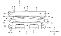
- FIG. 3 is a front view of the spring contact 10.
- FIG. 4 is a sectional view taken along line AA of FIG. 3.
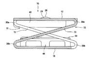
- FIG. 3 is a perspective view showing a state where a pressing force is applied to a spring contact 10.
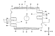
- FIG. 4 is a bottom view of the spring contact 10.
- FIG. 4 is a plan view in which a spring contact 10 is mounted along a curved shape of a printed circuit board. It is sectional drawing of the spring contact which made the strip
- FIG. It is a perspective view of spring contact 10a concerning a 2nd embodiment. It is a perspective view from another viewpoint of the spring contact 10a. It is a perspective view from another viewpoint of the spring contact 10a. It is a perspective view of spring contact 10b concerning a 3rd embodiment. It is a perspective view from another viewpoint of the spring contact 10b. It is an outline view of an intermediate produced in a manufacturing stage of spring contact 10b. It is explanatory drawing which shows a mode that a 1st plane part is pressed.
- FIG. 9 is an explanatory diagram regarding a case where a bending angle ⁇ is set to a different value.
- the spring contact is for electrically connecting the upper and lower connection objects.
- a spring contact may be a case in which conductive patterns on a printed circuit board are electrically connected to each other.
- one printed board may be a rigid board, and the other printed board may be a flexible board.
- the spring contacts are fixed and joined to the conductor pattern of the rigid board (corresponding to the lower connection target), and the spring contacts are connected to the electrically connected member (the upper connection target such as the conductor pattern of the flexible board). (Equivalent) will be described as an example.
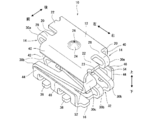
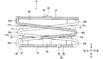
- FIG. 1 is a perspective view of a spring contact 10 according to the first embodiment.
- the spring contact 10 includes a continuous first plane portion 12, a band portion 14 serving as a spring portion, and a second flat portion 16.
- a long plate-shaped metal strip (hoop material) 18 is divided into portions that become the first flat portion 12, the strip portion 14, and the second flat portion 16.
- the spring contact 10 is formed by performing a cutting process (punching process) so as to obtain a plurality of spring contacts and a bending process or the like of each band-shaped portion 14. Cutting and bending can be performed by pressing.
- the spring contact 10 is separated from the metal strip 18 before or after bending.
- the metal strip 18 is made of a metal such as phosphor bronze, beryllium copper, or brass. Before or after the pressing, a plating layer such as a tin plating layer or a gold plating layer may be formed on the surface of the metal strip 18. In addition to forming the spring contact 10 from the metal strip 18, the spring contact 10 may be formed from a single metal plate.
- each of the upper and lower second plane portions 16 in FIG. 2 corresponds to the first element according to the present invention, and the other corresponds to the first element. This corresponds to the second element according to the present invention.
- the first flat portion 12 is a flat shape having a vertical direction in a thickness direction, and is a portion to be a contact to be pressed by the electrically connected member.
- the first plane portion 12 is formed in a polygonal shape having an even number of sides (a rectangular shape in the present embodiment), and can form a stopper 40 described later.
- the corner of the polygonal shape may be a rounded shape such as an R shape.
- An example of the size when the first flat portion 12 is viewed in plan is about 1.4 ⁇ 1.0 mm, but is not limited to this size.
- the protruding portion 22 is provided on the opposing edge 20 of the first flat portion 12, but the protruding portion 22 may not be formed as necessary.
- a part 23 of the convex part 22 is a part separated from the metal strip 18.
- the first flat portion 12 and the second flat portion 16 are parallel to each other in an initial state where no pressing force is applied to the first flat portion 12.
- a convex portion 24 is provided at the center of the first flat portion 12 to be in contact with the upper connection target. As shown in FIGS. 3 and 4, the convex portion 24 has a mountain shape that is point-symmetric with respect to the vertex 26.
- the convex portion 24 can be formed by pressing at the time of the press working.
- the electric connection member applies a pressing force to the first flat portion 12 by pressing the vertex 26 of the convex portion 24. Since the convex portion 24 is located at the center of the first flat portion 12 and the vertex 26 is located at the center of the first flat portion 12, the pressing force of the electrically connected member is evenly applied to the entire first flat portion 12. .
- the shape of the spring contact 10 is 180 ° rotationally symmetric with respect to an axis passing through the vertex 26 (the center of the first plane portion 12) and orthogonal to the first plane portion 12 (a shape rotated 180 ° from the original shape).
- the first plane portion 12 and each band-shaped portion 14 which are a part thereof are also similarly 180 ° rotationally symmetric.
- the shape of the first flat portion 12 can be viewed as 180 ° symmetric (point symmetry) with respect to the center of the first flat portion 12 when the first flat portion 12 is viewed in plan.
- the pressing force is evenly applied from the first flat portion 12 to the belt portion 14, and the first flat portion 12 can be moved while maintaining parallelism with the second flat portion 16 as described later.
- the size of the convex portion 24 is not limited, but when mounting the spring contact 10, if the first flat portion 12 is sucked by the suction nozzle, the convex portion 24 is made smaller than the suction port of the suction nozzle, The first flat portion 12 can be sucked by the suction nozzle. Note that the convex portion 24 may be omitted as long as the electrically connected member can uniformly press the entire first flat portion 12.
- the band portion 14 is a band-shaped portion formed by bending between the first plane portion 12 and the second plane portion 16, and serves as a spring portion.
- one ends 28 of the two band-shaped portions 14 are respectively connected to left and right end sides 20 of the first flat portion 12.
- the width of the band portion 14 is smaller than 1 / of the width of the edge 20 of the first flat portion 12 so that the band portions 14 do not come into contact with each other.
- the band portion 14 includes two or more bent portions 30a, 30b, and 30c. In this embodiment, three bent portions are formed for each band portion 14 as described above.
- a portion connecting the bent portions 30a, 30b, and 30c is formed in a straight line, and becomes the straight portions 31a and 31b.
- the two band portions 14 are arranged so as to meander from the first plane portion 12 to the second plane portion 16.
- the bent portion 30c has substantially the same horizontal position as the upper and lower bent portions 30a, 30b of the other band-shaped portion 14.
- each of the belt-shaped portions 14 is formed so as to partially overlap when viewed from the front, and meandering using a sufficiently large space between the first flat portion 12 and the second flat portion 16 can be realized. It is easy to have good properties as a spring.
- the two band-shaped portions 14 are arranged with their positions shifted in the front-rear direction, even if they are formed so as to partially overlap each other, it is possible to avoid contact with each other. is there.
- each band 14 is rotationally symmetric with respect to the axis described above by 180 °, and the bending angles of the bent portions 30a, 30b, 30c of each band 14 are also equal.
- the bent portions 30a, 30b, and 30c are bent so that the first flat portion 12 and the straight portion 31a, the straight portion 31a and the straight portion 31b, and the straight portion 31b and the second flat portion 16 have an acute angle.
- the bending angle of each bent portion 30a, 30b, 30c is not limited to the acute angle described above, and the angle may be increased as long as the band portion 14 can function as a spring.
- the angle of each bent portion 30a, 30b, 30c may be 90 ° or the like.
- the pressing force is uniformly applied from the first flat portion 12 to each band-shaped portion 14. Since the strips 14 are rotationally symmetrical by 180 ° as described above, the strips 14 are simultaneously compressed to have the same shape.
- the first flat part 12 moves without being twisted with respect to the second flat part 16, while maintaining the state where the first flat part 12 is parallel to the second flat part 16. Since the strips 14 are arranged so as to have the above-described 180 ° rotational symmetry, the strips 14 can be prevented from being twisted and plastically deformed.
- the bent portions 30a, 30b, 30c are R-shaped. Since the bent portions 30a, 30b, and 30c have an R shape, the band portion 14 can have elasticity, and the band portion 14 can maintain its function as a spring. When the first flat portion 12 is pressed and the pressing force is released, the first flat portion 12 returns to the original position, and the spring contact 10 returns to the original state.
- the bent portions 30a, 30b, and 30c of the band portion 14 include a first bent portion 30a that is continuous with the first flat portion 12, a second bent portion 30b that is continuous with the second flat portion 16, and the first bent portion 30a and the second bent portion 30b. It comprises a third bent portion 30c formed between the bent portion 30b.
- the first bent portion 30a is narrower and narrower than the second bent portion 30b.
- the second bent portion 30b has a notch 32 into which the first bent portion 30a enters. Note that the notch 32 may be slightly formed in the straight portion 30b. As shown in FIG. 6, when the band portion 14 is strongly compressed and elastically deformed, the first bent portion 30 a can enter the notch 32.
- the notch 32 into which the first bent portion 30a enters is formed in the second bent portion 30b, not only the amount of deformation of each bent portion 30a, 30b, 30c can be increased, but also the entire spring contact 10 becomes bulky. Can be prevented, and the stroke when the electrically connected member presses the first flat portion 12 can be lengthened. At this time, the straight portions 31a and 31b bend and contribute to the spring function of the band portion 14. The notch 32 can be omitted if the stroke can be short.
- the bending portions 30a, 30b, and 30c adjust the bending angle of the spring contact 10 in the initial state (the state in which the first flat portion 12 is not pressed) to adjust the size of the electronic device on which the spring contact 10 is mounted.
- the distance from the first flat portion 12 to the second flat portion 16 is adjustable.
- the distance from the first plane part 12 to the second plane part 16 is about 3.0 to 1.0 mm.
- the bending angles of the bent portions 30a, 30b, and 30c may be appropriately adjusted according to the stroke when the electrically connected member presses the first flat portion 12.
- the second flat portion 16 is a portion that is electrically joined to the conductor pattern of the printed board by soldering or the like, and is formed continuously at each end of the two band-shaped portions 14. I have. Specifically, the two second plane portions 16 are planar, and the other end 36 of the band portion 14 is connected to the edge 34 of the second plane portion 16, and the two second plane portions 16 are described later. The part 16 is integrated by the fitting part 58. Since the two second flat portions 16 are flush with each other, the two second flat portions 16 are integrally joined to the conductor pattern.
- the second flat portion 16 has a polygonal shape having an even number of sides (a rectangular shape in the present embodiment), and can form a guide 44 described later. The corner of the polygonal shape may be a rounded shape such as an R shape.
- the second flat portion 16 may be formed by soldering the entire contact surface with the conductor pattern to the conductor pattern, or only the side portion 38 of the contact surface may be soldered to the conductor pattern. Soldering can be performed by an arbitrary method such as a reflow method.
- the first flat portion 12 forms the stopper 40.
- the stopper 40 is a portion of the first flat portion 12 where the side edge 42 (each of the front and rear ends) where the belt-shaped portion 14 is not connected is bent toward the second flat portion 16 toward the bent portions 30b and 30c.
- the stopper 40 is arranged perpendicularly to the first plane portion 12.
- the stoppers 40 are formed at two places so as to face each other in parallel. When the first flat portion 12 is pressed toward the second flat portion 16, the tip of the stopper 40 is brought into contact with the second flat portion 16, thereby preventing the first flat portion 12 from moving more than necessary.
- the stopper 40 prevents the first flat portion 12 from moving too much and the spring contact 10 from being deformed.
- the height of the stopper 40 the movable distance of the first flat portion 12 can be changed. Further, the strength of the spring contact 10 can be increased by arranging the stopper 40 to bend in the vertical direction with respect to the first plane portion 12.
- the second flat portion 16 includes the guide 44.
- the guide 44 is a portion of the second flat portion 16 in which the side edges 46 (front and rear ends) of the second flat portion 16 that are not connected are bent toward the first flat portion 12 toward the bent portions 30a and 30b.
- the guide 44 is arranged perpendicular to the second plane portion 16.
- the guides 44 are formed at two places so as to face each other in parallel.
- the two stoppers 40 move between the guides 44 facing each other.
- the outer surface of the stopper 40 and the inner surface of the guide 44 are surfaces facing each other in the front-rear direction (opposed surface). The positional relationship between the stopper 40 and the guide 44 is determined by sliding the outer surface of the stopper 40 while contacting the inner surface of the guide 44.
- the outer surface of the stopper 40 and the inner surface of the guide 44 are closely opposed to each other, so that the outer surface of the stopper 40 and the inner surface of the guide 44 are always kept parallel to each other. It is possible to prevent relative rotation and the like when viewed from above.
- the height of the guide 44 By appropriately changing the height of the guide 44, the length for guiding the stopper 40 can be changed. Further, the strength of the spring contact 10 can be increased by arranging the guide 44 so as to be bent in the vertical direction with respect to the second plane portion 16.
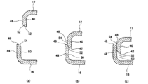
- the inclined surfaces 52 and 54 may be provided on the ends 42 and 46 of the stopper 40 and the guide 44 (FIG. 8A). Even if one of the two stoppers 40 descends so as to lie on the edge 46 of the guide 44, the inclined surface 52 comes into contact with the inclined surface 54 of the guide 44, so that the inner surface of the stopper 40 is inward. The guide 40 descends toward the second flat portion 16 while being guided (FIG. 8B), and the stopper 40 moves on the inner surface side of the guide 44 (FIG. 8C). Even if a slight dimensional error occurs during the formation of the spring contact 10, the outer surface 48 of the stopper 40 can be reliably arranged on the inner surface 50 side of the guide 44 by the inclined surfaces 52 and 54. Note that the inclined surfaces 52 and 54 may be omitted.
- the stopper 40 is provided on the first flat portion 12 and the guide 44 is provided on the second flat portion 16, but the stopper 40 may be provided on the second flat portion 16 and the guide 44 may be provided on the first flat portion 12.
- the number of the stopper 40 and the number of the guides 44 are not limited to two, but may be one.
- the stopper 40 and the guide 44 need not be provided.
- only the stopper 40 may be provided. In this case, it may be provided only on the first flat portion 12, may be provided only on the second flat portion 16, or may be provided on the first flat portion 12 and the second flat portion 16.
- the two second flat portions 16 include fitting portions 58 that are fitted to the opposing side portions 56.
- the fitting portion 58 is formed by, for example, an L-shaped convex portion 60 and a concave portion 62 into which the convex portion 60 is fitted.
- the convex portion 60 enters the concave portion 62, the movement of the second flat portion 16 in a direction orthogonal to the compression direction of the band portion 14 can be restricted. Since the two second plane portions 16 can be prevented from shifting in the plane direction, and the two second plane portions 16 can be kept in an integrated state, the shape of the spring contact 10 can be easily maintained.
- a printed board having the spring contact 10 By electrically connecting the spring contact 10 to the conductor pattern of the printed board with solder or the like, a printed board having the spring contact 10 can be configured. Since the spring contact 10 of the present application has a very small shape as described above, the spring contact 10 can be mounted along the curved shape 66 of the printed board 64 as shown in FIG. The proportion of the mounting area on the printed board 64 can be increased, and the printed board 64 can be mounted at a high density.
- the electronic device of the present embodiment is a device provided with a printed board 64 on which the spring contact 10 is mounted.
- Electronic devices include any devices such as smartphones, tablets, mobile phones, laptop computers, digital cameras, televisions, audio devices, and various remote controls. Further, the electronic device is not limited to a single product, and includes a module that performs a predetermined function such as a car audio system and a car navigation system mounted on an automobile. If the printed circuit board 64 is mounted with high density as described above, the size of the electronic device can be reduced.
- the first plane portion 12 can be moved while maintaining the parallel state with respect to the second plane portion 16, so that the band portion 14 can be prevented from being twisted and plastically deformed.
- the shape of the spring contact 10 can be maintained even if connection and disconnection between the conductor pattern and the electrically connected member are repeated. Therefore, the spring contact 10 can ensure electrical connection and disconnection.
- the spring contact 10 of the present invention can also be used as a proximity sensor or a switch.
- the shape of the first plane portion 12 may be an arbitrary shape such as a polygon including a square or a rectangle, a circle, or an ellipse.
- the shape in a state where the two second plane portions 16 are integrated may be any shape such as a polygon, a circle, and an ellipse.
- the first plane portion 12 and the second plane portion 16 may have different shapes. Further, the shapes of the first plane portion 12 and the second plane portion 16 may have any irregularities on the outer periphery.
- the number of the bent portions 30a, 30b, and 30c of the band portion 14 is three, but the number can be set arbitrarily.
- the band-shaped portion 72 includes two bent portions, that is, a first bent portion 30a and a second bent portion 30b, and further includes a straight portion 73 between the bent portions 30a and 30b. ing.
- the first flat portion 12, the band portion 72, and the second flat portion 16 are formed such that the side view becomes a Z shape.
- the first flat portion 12 may rotate slightly in the flat direction while keeping parallel to the second flat portion 16, but the present invention can be applied to the spring contact 70 having a short stroke.
- the second flat portion 16 is connected to the substrate so as to be slidable in a conductive state with respect to the substrate, whereby the first flat portion 12 can be moved without rotating in the planar direction. Further, the number of bent portions included in one belt-shaped portion may be four or more.
- the number of the band-shaped portions 14 can be set arbitrarily as long as the first flat portion 12 can move while keeping the second flat portion 16 parallel.
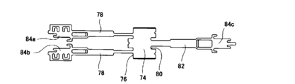
- two strips 78 may be connected to one end 76 of the first flat portion 74, and one strip 82 may be connected to the other end 80.
- the elastic force is adjusted by changing the width of the belt-shaped portions 78 and 82 so that the first flat portion 12 can move while keeping parallel to the second flat portions 84a, 84b and 84c.
- the length direction of the band portion 14 may be oriented in any direction with respect to the first plane portion 12, and the two band portions 14 do not face the above-described 180 ° rotationally symmetric direction, It may face any direction.
- the shape is not limited to the linear shape.
- the space between the bent portions 30a, 30b, 30c may be curved or meandering.
- a belt-like portion may be used in which the bent portions 30a, 30b, and 30c are directly connected to each other and the straight portions 31a and 31b are omitted.
- the first bent portion 30a is formed continuously with the first flat portion 12 and the second bent portion 30b is formed continuously with the second flat portion 16, but the first bent portion 30a is formed continuously with the second flat portion. 16, the second bent portion 30b may be formed continuously with the first flat portion 12.
- fitting portions 58 are provided on the second flat portion 16 in FIG. 7, one fitting portion 88 may be used like the second flat portion 86 in FIG.
- the fitting portions 58 and 88 are not limited to the above-described convex portions 60 and concave portions 62 as long as the position of the second flat portion 12 can be regulated.
- the fitting portion 92 may be formed in a stepped shape to prevent the mutual stepped shape from shifting the position of the second flat portion 90.
- the configuration of the spring contact 10 shown in the above embodiment may be used upside down.
- the second flat portion 16 is on the contact side pressed by the electrically connected member, and the first flat portion 12 is connected to the conductor pattern of the printed board by soldering or the like. Are electrically joined.
- connection of the conductor pattern of the rigid board and the conductor pattern of the flexible board has been described.
- connection of the conductor patterns of the rigid board or the connection of the conductor patterns of the flexible board may be made.
- a spring contact may be bonded to the conductor pattern of the flexible board, and the conductor pattern of the rigid board may press the first plane portion.
- the two objects to be connected by the spring contact are not limited to the connection of the conductor pattern of the printed circuit board, but may be used for the terminal connection of the wire harness. Therefore, the electronic device of the present application is not limited to the electronic device including the printed circuit board on which the spring contact is mounted, but is included in the electronic device by an arbitrary method.
- the spring contact according to the present embodiment is configured such that each end of the band-shaped portion is continuous with the first plane portion and the second plane portion shape, and the first plane portion is connected to the second plane portion via the bent band-shaped portion.
- the band portion is deformed to be compressed.
- the first flat portion can be moved while keeping the first flat portion parallel to the second flat portion, and the belt-like portion can be prevented from being deformed or damaged, and can be prevented from being deformed. Part inclination can also be prevented.
- the strip can be restored to its original shape even after repeated electrical connection and disconnection. Therefore, the shape of the spring contact is maintained, and the spring contact can maintain a desired electrical connection.
- the belt-like portion is formed in a shape that is 180 ° rotationally symmetric with respect to the center of the first plane portion, and two or more bent portions that are 180 ° rotationally symmetric are formed so that the bending angles are equal.
- the plane part and the second plane part can be kept parallel without tilting.
- the notch is formed in the bent portion, the amount of compression of the bent portion can be increased as much as possible, and the height of the entire spring contact can be reduced while maintaining the predetermined amount of compression.
- the stopper and the guide it is possible to more reliably keep the first plane portion and the second plane portion parallel without deforming or breaking the spring contact.
- the fitting portion in the second flat portion, the movement of the second flat portion in the planar direction can be regulated by the fitting portion, so that the shape of the spring contact can be easily maintained.
- the spring contact of this embodiment can be mounted on a printed circuit board at high density, and the printed circuit board can be downsized. Therefore, the electronic device having the spring contact according to the present embodiment can be downsized. Further, the spring contact of the present embodiment has a shorter conduction distance than a conventional one, so that high-speed circuits can transmit and receive signals at high speed.
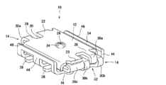
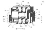
- FIGS. 13 to 15 are perspective views of the spring contact 10a according to the second embodiment viewed from another angle.
- the shape of the spring contact 10a according to the second embodiment also passes through the vertex 26 (the center of the first flat portion 12) and is orthogonal to the first flat portion 12 (the axis extending in the up-down direction).
- the first flat portion 12 and each band-shaped portion 14 as a part thereof are also 180 ° rotationally symmetric.
- One end 28 of each of the two band-shaped portions 14 provided on the spring contact 10a is connected to an end 20 of the first flat portion 12 facing the left and right. Further, a notch extending in the same direction as the direction in which the belt-shaped portion 14 extends is provided at the center in the front-rear direction of the first bent portion 30a and the second bent portion 20b. These notches are provided mainly to balance the stress generated in the band-shaped portion 14 during elastic deformation. For example, if the width of the band-shaped portion 14 is made uniform, the stress becomes higher in the vicinity of the first bent portion 30a and the second bent portion 20b than in the vicinity of the third bent portion 30a. It is possible to reduce such bias of stress.
- the first bent portion 30b can enter the notch formed in the second bent portion 30b.
- the second embodiment does not adopt such a configuration.
- a configuration that allows such entry may be adopted.
- the width of the band-shaped portion 14 is reduced near the first bent portion 30a and the second bent portion 20b as compared with the vicinity of the third bent portion 30a.
- the bias of the stress is similarly reduced.
- two second flat portions 16 portions connected to separate strip portions 14 and correspond to the first and second elements according to the present invention
- the second planar portions 16 are not provided, and the edges of the second planar portions 16 are opposed to each other so as to be close to the left and right, and the lower surfaces thereof are on the same plane.
- a fitting portion may be provided as in the first embodiment.
- the two second plane portions 16 can be used as soldering surfaces when fixing to a connection target using solder.
- each of the front and rear stoppers 40 of the second embodiment is provided with a fitting projection 40a
- each of the front and rear guides 44 is provided with a hole 44a into which the fitting projection 40a is fitted.
- the fitting projection 40a is fitted into the hole 44a, and the relative positional relationship between the first flat portion 12 and the second flat portion 16 is limited by the contact between the fitting projection 40a and the edge of the hole 44a. I am trying to be.
- the horizontal dimension of the hole 44a is constant regardless of the vertical position, and the dimension is slightly larger than the horizontal dimension of the fitting projection 40a.
- the fitting projection 40a and the hole 44a are aligned at the center in the left-right direction. Thereby, the left and right movement of the fitting projection 40a is suppressed by the contact with the left and right edges of the hole 44a, and the displacement of the relative positional relationship between the first plane portion 12 and the second plane portion 16 in the left and right direction is also suppressed. You. Furthermore, the rotation of the fitting projection 40a when viewed from above is also suppressed by the contact between the left and right end surfaces of the fitting projection 40a and the left and right edge surfaces of the hole 44a (a surface whose front-back dimension corresponds to the plate thickness).
- the relative displacement between the first plane portion 12 and the second plane portion 16 in the upward rotation direction is also suppressed.
- the vertical movement of the fitting projection 40a is not hindered unless the upper edge of the hole 44a is contacted.
- a component corresponding to the fitting projection 40a may be provided on the guide 44 side, and a component corresponding to the hole 44a may be provided on the stopper 40 side.
- the maximum distance between the first flat portion 12 and the second flat portion 16 is defined by the fact that the fitting projection 40a comes into contact with (hook) the upper edge of the hole 44a.
- the fitting projection 40a contacts the upper edge of the hole 44a, and
- the spring (spring that expands and contracts up and down) by the band-shaped portion 14 is set to be in a slightly contracted state.
- the first flat portion 12 and the second flat portion 16 are urged in a direction away from each other by the elastic force of the band portion 14.
- the distance between the first plane portion 12 and the second plane portion 16 in the initial state is stabilized at the above-described maximum distance. I can do it.
- the magnitude of the initial load it is also possible to adjust the initial contact force between the connection target and the first flat portion 12 (the contact force when the spring contact 10a starts to deform).
- the magnitude of the initial load and the magnitude of the maximum distance can be appropriately set according to the product specifications and the like.
- the conductive projections 44b projecting toward the outer surface (opposing surface) of the corresponding stopper 40 are provided on the inner surface of each of the front and rear guides 44.
- the conductive protrusions 44b can be formed by pressing the outer surface of the guide 44, as in the case of the protrusions 24.
- the concave portion 44c formed on the outer surface of the guide 44 is formed by the pressing process.
- the conductive protrusions 44b are in contact with the opposing surface of the stopper 40, and thereby each of the guides 44 and the conductive protrusions 44b are brought into contact with each other via the conductive protrusions 44b. It is possible to form a conductive path.
- the conductive path is shorter than the conductive path when the guides 44 and the conductive protrusions 44b are not in contact (a conductive path between the first flat portion and the second flat portion via the strip portion 14).
- the tip of the conductive protrusion 44b be pressed against the outer surface of the stopper 40.
- a component corresponding to the conductive protrusion 44b may be provided on the outer surface of the stopper 40, and may be brought into contact with the inner surface of the guide 40.
- the conductive projections 44b are prevented from contacting the stopper 40, and are brought into contact at a stage where the flat portion 12 has moved downward by a predetermined amount or more.
- the friction between the conductive projection 44b and the outer surface of the stopper 40 is suppressed, and the first plane portion 12 is designed to be easily moved downward as much as possible.
- the outer surface of the stopper 40 and the inner surface of the guide 44 are closely opposed to each other, so that the outer surface of the stopper 40 and the inner surface of the guide 44 are always kept parallel, and the upper surface of the first flat portion 12 and the second flat portion 16
- the point that relative rotation and the like by visual observation can be prevented is the same as in the case of the first embodiment.
- the present embodiment the same applies to a third embodiment described later
- the outer surface of the stopper 40 and the inner surface of the guide 44 are closely opposed to each other. Can be.
- the effect of suppressing the positional shift by the combination of the fitting projection 40a and the hole 44a described above is also effective in the initial state.
- the spring contact 10a of the present embodiment in the initial state even if an unintended external force is applied to the spring contact 10a of the present embodiment in the initial state, deformation, breakage, and the like are suppressed as much as possible.
- the spring contact is often handled in an initial state in which the connection target has not yet contacted the first flat portion 12, and it is important that deformation, breakage, and the like be suppressed even in the initial state.
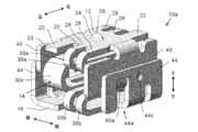
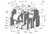
- FIGS. 16 and 17 are perspective views of the spring contact 10b according to the third embodiment viewed from another angle.
- the shape of the spring contact 10b according to the third embodiment also passes through the vertex 26 (the center of the first plane portion 12) and is orthogonal to the first plane portion 12 (the axis extending in the vertical direction).
- the first flat portion 12 and each band-shaped portion 14 as a part thereof are also 180 ° rotationally symmetric.
- the vertical dimension of the spring contact 10b varies from about 0.9 mm (pressed state) to about 1.2 mm (initial state).
- each of the front and rear stoppers 40 is provided with two fitting projections 40a1 and 40a2, and each of the front and rear guides 44 is provided with two holes 44a1 and 44a2.
- the fitting projection 40a1 is provided on the left side of the stopper 40, and the fitting projection 40a2 is provided on the right side of the stopper 40.
- the hole 44a1 is provided at a position of the guide 44 where the fitting protrusion 40a1 is fitted, and the hole 44a2 is provided at a position of the guide 44 where the fitting protrusion 40a2 is fitted.
- fitting projections 40a1 and 40a2 and the holes 44a1 and 44a2 are basically the same as those in the second embodiment.
- the displacement of the relative positional relationship between the first flat portion 12 and the second flat portion 16 in the left-right direction is more effectively suppressed by increasing the number of combinations of fitting protrusions and holes. It is possible.
- a total of four combinations of fitting projections and holes corresponding to each other are arranged so as to be substantially symmetrical in both front and rear and right and left when viewed from above. It is possible to further stabilize the shape in the above.
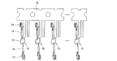
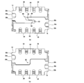
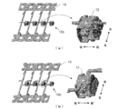
- the spring contact is manufactured from a metal strip (metal plate) cut (punched) so as to obtain a plurality of spring contacts.
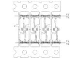
- the state immediately before the spring contact is cut out of the metal strip is in the form shown in FIG. In FIG. 18, an enlarged view of a portion surrounded by a broken line frame is shown on the right side.
- other portions of the metal strip are connected to the front and rear edges of the first flat portion 12 in the spring contact 10b, and the spring contact 10b is obtained by cutting the vicinity of the connection portion.
- a portion 23a of the front and rear ends of the first flat portion 12 is a portion separated from the other portions of the metal strip.
- the part 23a of the end portion is positioned slightly below the outer surface of the first flat portion 12 by bending, so that contact with the connection target (see FIG. 19) is avoided as much as possible. ing.
- the form of the intermediate is not particularly limited as long as a spring contact can be appropriately obtained. For example, as shown in FIG. 18B, other portions of the metal strip are connected to the left and right edges of the first flat portion 12 in the spring contact 10b, and the vicinity of the connection portion is cut to form the spring contact. 10b may be obtained.
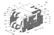
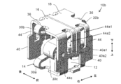
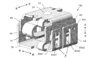
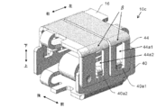
- FIGS. 20 and 21 are perspective views of the spring contact 10c according to the fourth embodiment viewed from another angle.
- the lower side of the two holes 44a1 and 44a2 formed in the front and rear guides 44 is a bent portion between the second plane portion 16 and the front and rear guides 44. It does not extend to the R portion of ⁇ (the curved surface portion formed by bending the metal plate material). Therefore, in the fourth embodiment, no hole is provided in the R portion of the bent portion ⁇ , and the R portions of the bent portion ⁇ are continuously connected at the entire front and rear ends of the second flat portion 16.
- the connection target in the process of mounting the spring contact 10c on the lower connection target, it is possible to solder the range enclosed by the broken line (the range indicated by hatching) shown in FIG. 21 to the connection target. That is, not only the second flat portion 16 but also a wide range of the R portion of the bent portion ⁇ can be soldered to the connection target, and the spring contact 10c can be more securely connected and fixed to the connection target. Further, when the second flat portion 16 is fixed to the connection target by reflow soldering, the surface tension of the solder at the R portion is increased, and it is possible to suppress a situation in which the spring contact 10c rotates unintentionally. .
- the two right and left fitting projections 40a1 and 40a2 are formed by bending a part of the guide 40 outward.
- the bending angle (bending angle ⁇ ) may be set to various values. It is possible.
- FIGS. 22A to 22C shows the spring contact 10c when the bending angle ⁇ is set to a different value.
- the upper side shows an external perspective view of the spring contact 10c
- the lower side shows a cross-sectional view (a cross-sectional view taken along a plane perpendicular to the left-right direction passing through the fitting projection 40a1). I have.
- the bending angle ⁇ in FIG. 22A is approximately 180 °, and the fitting projections 40 a 1 and 40 a 2 are bent so as to be in close contact with the guide 40.
- the protrusion amount ⁇ of the fitting projections 40a1 and 40a2 in the front-rear direction from the guide 40 is approximately equivalent to the plate thickness of the fitting projections 40a1 and 40a2.
- the bending angle ⁇ in FIG. 22B is slightly smaller than the bending angle ⁇ in FIG.
- the protrusion amount ⁇ in FIG. 22B is larger than the protrusion amount ⁇ in FIG. Therefore, in the spring contact 10c shown in FIG. 22B, even when an external force in the front-rear direction is applied to the guide portion 40 as illustrated by the white arrow in FIG.
- the projections 40a1 and 40a2 can be made hard to deviate from the holes 44a1 and 44a2. Thereby, it is possible to make it difficult for the hooks of the fitting projections 40a1 and 40a2 (the hooks on the upper edges of the holes 44a1 and 44a2) to come off.
- the bending angle ⁇ is smaller than that shown in FIG. 22 (B), and the protruding amount ⁇ is correspondingly larger.
- a gap is formed between the guide 44 and the fitting projections 40a1 and 40a2, the gap having a size enough to receive the upper edges of the holes 44a1 and 44a2. Therefore, at least in the initial state, the upper edges of the holes 44a1 and 44a2 of the spring contact 10c are in a state of being fitted between the guide 44 and the fitting protrusions 40a1 and 40a2.
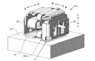
- FIG. 23 is a perspective view of a spring contact 10d according to the fifth embodiment.
- a reinforcing portion 45 is provided so as to be connected to one end of the guide 40 in the left-right direction. More specifically, a portion of the metal plate connected to the left side of the front guide 40 is bent backward by 90 ° to form the left reinforcing portion 45. On the other hand, the metal plate connected to the right side of the rear guide 40 is bent forward by 90 ° to form the right reinforcing portion 45.
- the lower end 45a together with the second flat portion 16 may be soldered to the upper plane of the connection target Ob1.
- the lower end 45a can also be soldered to the connection target Ob1, and unintended deformation of the spring contact 10d and peeling from the connection target Ob1 can be suppressed.
- the lower end portion 45a is in contact with the connection target Ob1, and therefore the deformation such that the upper side of the guide 40 falls backward by the support of the reinforcing portion 45 is prevented.
- a force is generated to press the lower end 45a against the connection target Ob1, and this force acts to prevent the lower end 45a and the connection target Ob1 from being separated from each other by soldering.
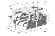
- FIG. 25 is a perspective view of a spring contact 10e according to the sixth embodiment.
- FIG. 26 is a cross-sectional view of the spring contact 10e shown in FIG. 25 (a cross-sectional view when the spring contact 10e is cut in a plane that divides the spring contact 10e forward and backward).
- a groove 40x and a claw 44x are provided instead of the fitting projections 40a1, 40a2 and the holes 44a1, 44a2.
- the stopper 40 is provided with two vertically extending grooves 40x arranged side by side.
- the guide 44 is provided with two claw portions 44x corresponding to the two groove portions 40x, respectively.
- the claw portion 44x is bent inward in the front-rear direction from the upper end of the guide 44, and is formed so as to fit into the corresponding groove portion 40x.
- the width (dimension in the left-right direction) of the claw 44x is equal to or slightly smaller than the width of the groove 40x.
- the claw portion 44x is relatively movable vertically in the groove portion 40x.
- the first flat portion 12 can be prevented from being displaced in the left-right direction.
- the claw portion 44x is hooked on the lower edge of the groove portion 40x, the upward movable range of the first flat portion 12 can be restricted.
- a wall portion 49 having a thickness direction in the left-right direction is provided on each of the left and right sides of the spring contact 10e.
- the left wall portion 49 has a rearward portion projecting upward so as to protect the rear band portion 14 from the left side.
- the right wall portion 49 has a forward portion projecting upward so as to protect the front band portion 14 from the right side.
- a predetermined portion (for example, a portion indicated by Q2 in FIG. 25) of the first flat portion 12 comes into contact with an upper end (for example, a portion indicated by Q1 in FIG. 25) of these overhanging portions.
- the downward movable range can be regulated.
- the leftward portion of the front guide 44 is formed as a portion bent 90 degrees to the right from the front end of the left wall portion 49, and the rightward portion is formed from the front end of the right wall portion 49 to the left. It is formed as a part that is bent 90 degrees to the right.
- the leftward portion of the rear guide 44 is formed as a portion bent 90 degrees to the right from the rear end of the left wall portion 49, and the rightward portion of the right wall portion 49 is formed. It is formed as a portion bent 90 degrees to the left from the rear end.
- Each of the leftward and rightward portions of the front guide 44 and the leftward and rightward portions of the front guide 44 are provided with extensions 44z that are bent 90 degrees inward in the front-rear direction from a part of the lower end. Have been.
- the extension part 44z functions as a part of the second plane part 16 in the fourth embodiment.
- One end of the front band portion 14 is connected to the first flat portion 12, while the other end is connected to the upper side of the front portion of the left wall portion 49.
- One end of the rear band portion 14 is connected to the first flat portion 12, while the other end is connected to an upper side of a rearward portion of the right wall 49.
- the spring contact 10e has a lower edge of each of the front and rear guide portions 44 and a lower edge of each of the left and right wall portions 49 (each of which corresponds to a side surface of a metal plate material), and each extension portion 44z has a lower portion.
- these downwardly exposed portions are on the same plane, and this plane (virtual plane) is parallel to the first plane portion 12.
- the spring contact 10e of the present embodiment can easily adjust the vertical dimension in accordance with various circumstances by providing a padding (addition of a plate material element) under each guide portion 44 and each wall portion 49. It is.
- FIG. 27 shows a spring contact 10e1 adjusted to have a larger vertical dimension than the spring contact 10e shown in FIG.
- the elements between the dashed lines Y1 and Y2 shown in FIG. 27 are overlaid, and the dimension in the vertical direction is increased by that amount.
- the metal plate for manufacturing the original spring contact 10e may be overlaid. More specifically, a colored plate portion (a portion between the broken line Y1 and the broken line Y2 after manufacturing) may be overlaid on the metal plate material shown in FIG. Thereby, the spring contact 10e1 after the dimension adjustment can be easily manufactured without changing the basic manufacturing process.
- the spring contact according to each of the above-described embodiments is a spring contact that electrically connects upper and lower connection targets, has a first flat portion 12, and has a connection portion connected to the upper connection target, At least two strips 14 formed as springs, one end of which is formed to be continuous with the end of the first flat part 12 and provided with two or more bent parts by bending, and the other end of each of the strips 14 And a base portion formed continuously and connected to a lower connection target. Further, when the connecting portion is pressed downward, each of the belt-shaped portions 14 receives the load of the pressing uniformly, and is elastically deformed so that the connecting portion moves downward in parallel.
- connection portion having the first flat portion 12 and the connection target can be further stabilized while the movement of the first flat portion 12 is not limited by the plate width of the spring. It is also possible to maintain the parallel of the flat portions (the first flat portion 12 and the second flat portion 16).
- the second flat portion 16 of the first to fifth embodiments, and the guide 44 and the wall portion 49 of the sixth embodiment can be regarded as one form of the base portion according to the present invention.
- connection part does not move in parallel, the contact between the connection part and the connection target becomes unstable, or friction occurs between the contact and the connection target every time the spring expands and contracts, which causes factors such as wear. Or there is a risk of In order to make such a phenomenon easier to understand, the second connection target Ob2 (the substrate facing downward) is moved downward with respect to the spring contact with the second flat portion 16 connected and fixed to one connection target Ob1.
- FIG. 19 schematically shows how the connection portion is pressed.
- FIG. 19 shows that when the connection target Ob2 moves downward in the state shown in FIG. 19A, the connection part is pressed downward and the state shown in FIG. 19B is obtained.
- the connecting portion 12 moves downward in parallel, and the same applies to a case where the first flat portion 12 is not provided with the convex portion 24.
- friction may be generated particularly between the vicinity of the apex 26 of the projection and the connection target Ob2.
- the moving direction (vertical direction) of the flat portion is orthogonal to the plate width direction (front-back direction) of the spring, and the movement of the flat portion is not limited by the plate width of the spring.
- first plane portion 12 and the second plane portion 16 in each embodiment can not only maintain the parallelism as described above, but also prevent the relative rotation when viewed from above. Therefore, a situation in which the rotation causes friction between the vicinity of the vertex 26 of the convex portion and the connection target Ob2 is also avoided.
- the spring contact according to each embodiment is taken out of the embossed tape (packaging material) or the like by sucking the first flat portion 12 using a suction nozzle (suction nozzle), the suction nozzle is lightly moved to the first flat portion 12. If the first flat portion 12 rotates in such a manner when pressed, there is a possibility that the suction to the suction nozzle may be hindered.
- the second flat portion 16 causes such rotation. Then, there is a possibility that the fixing position of the spring contact in the connection target Ob1 is shifted. If the relative rotation of the first flat portion 12 and the second flat portion 16 as viewed from above is suppressed, such a problem can be solved.
- each of the band-shaped portions 14 is elastically deformed while pressing against the other one of the first flat portion 12 and the second flat portion 16 while suppressing the tilting of the flat portions. It can.
- FIG. 5 a view from the front perspective
- the first flat portion 12 convex portion 24
- the first flat portion 12 tilts to the left or right (that is, the rotational motion is reduced). It is easy to move downward.
- this strip 14 is elastically deformed while acting to suppress the movement of the other strip 14 in which the tilting occurs. It is possible to move the first plane portion 12 downward while maintaining the parallelism as much as possible.
- the two band-shaped portions 14 are formed such that one is continuous with the left side edge of the first flat portion 12 and the other is continuous with the right side edge of the first flat portion 12. .
- Each of the two belt-like portions 14 is formed so as to be shifted in the front-rear direction and partially overlap when viewed from the front. Therefore, it is possible to arrange each of the band-shaped portions 14 using a sufficiently large space between the first plane portion 12 and the second plane portion 16 when viewed from the front, and to avoid contact between the band-shaped portions 14. It is possible.
- Each of the two band-shaped portions 14 is rotationally symmetric with respect to an axis extending in the vertical direction through the center of the first plane portion 12 (an axis orthogonal to the first plane portion 12). Thereby, it is possible to minimize the deviation of the positions and characteristics of the band-shaped portions 14 as much as possible, and each band-shaped portion 14 receives the pressing load of the flat portion evenly, so that the elasticity is maintained so that the flat portions are maintained in parallel. The effect of deformation can be obtained more reliably and easily. Further, since the convex portion 24 for contacting the connection target is provided at the center of the first flat portion 12, it is easy to press the center of the first flat portion 12 on the upper connection target.
- the front and rear edges of the first flat portion 12 are bent downward to form the stopper 40 (first bent portion), and the front and rear edges of the second flat portion 16 are formed.
- a guide 44 (second bent portion) is formed by bending upward. Then, the opposing surfaces facing the front and rear of the stopper 40 and the guide 44 are brought close to each other, so that the relative positional relationship between the first plane portion 12 and the second plane portion 16 is limited by the contact between the opposing surfaces. I have.
- the first bent portion is formed by bending only one of the front sides and the rear side of the first flat portion 12 downward, and the second bent portion is formed on one of the front side and the rear side of the second flat portion 16. Only the end side may be bent upward.
- the spring contact of each embodiment is formed by a forming method including a step of bending a metal strip (metal plate).
- a metal plate metal plate
- one end of a component of the first plane portion 12 is connected in sequence with a component of one of the band portions 14 and a first element which is a part of a component of the second plane portion 16, At the other end of the component of the portion 12, the component of the other band portion 14 and the second component, which is the remaining component of the component of the second flat portion 16, are sequentially connected.
- the first element is connected in order from the first element to the one band-shaped part 14, the first plane part 12, the other band-shaped part 14, and the second element without the need for bonding or the like.
- the state can be realized, and it is possible to prevent the quality of the band-shaped portion 14 largely related to the spring performance from being deteriorated by adhesion or the like.
- the first element and the second element have a fitting structure in which one side can be fitted to the other side.
- the above-described forming method includes the fitting step. Therefore, it is possible to prevent the first element and the second element from being displaced in the plane direction, and to easily maintain the shape of the spring contact.
Landscapes
- Coupling Device And Connection With Printed Circuit (AREA)
- Manufacturing Of Electrical Connectors (AREA)
Priority Applications (2)
| Application Number | Priority Date | Filing Date | Title |
|---|---|---|---|
| CN201980050540.1A CN112534652B (zh) | 2018-07-31 | 2019-03-26 | 弹簧触头以及弹簧触头的形成方法 |
| JP2020534055A JP6823229B2 (ja) | 2018-07-31 | 2019-03-26 | バネコンタクト |
Applications Claiming Priority (2)
| Application Number | Priority Date | Filing Date | Title |
|---|---|---|---|
| JP2018144315 | 2018-07-31 | ||
| JP2018-144315 | 2018-07-31 |
Publications (1)
| Publication Number | Publication Date |
|---|---|
| WO2020026520A1 true WO2020026520A1 (ja) | 2020-02-06 |
Family
ID=69231564
Family Applications (1)
| Application Number | Title | Priority Date | Filing Date |
|---|---|---|---|
| PCT/JP2019/012840 Ceased WO2020026520A1 (ja) | 2018-07-31 | 2019-03-26 | バネコンタクトおよびバネコンタクトの形成方法 |
Country Status (3)
| Country | Link |
|---|---|
| JP (2) | JP6823229B2 (enExample) |
| CN (1) | CN112534652B (enExample) |
| WO (1) | WO2020026520A1 (enExample) |
Cited By (2)
| Publication number | Priority date | Publication date | Assignee | Title |
|---|---|---|---|---|
| JP2021180102A (ja) * | 2020-05-13 | 2021-11-18 | 株式会社T・P・S・クリエーションズ | コンタクト |
| KR20220065528A (ko) * | 2020-11-13 | 2022-05-20 | 주식회사 현대케피코 | 모터의 축방향 유동 감쇠를 위한 탄성부재 |
Citations (6)
| Publication number | Priority date | Publication date | Assignee | Title |
|---|---|---|---|---|
| US6489555B1 (en) * | 2001-08-17 | 2002-12-03 | Chin Fu Horng | Elastic system for preventing electromagnetic interference to a computer central processing unit |
| JP2007250320A (ja) * | 2006-03-15 | 2007-09-27 | Kitagawa Ind Co Ltd | コンタクト部材 |
| JP2011134713A (ja) * | 2009-12-23 | 2011-07-07 | Hon Hai Precision Industry Co Ltd | 電気コネクタ |
| JP2016126986A (ja) * | 2015-01-08 | 2016-07-11 | イリソ電子工業株式会社 | 接続端子 |
| JP2018056060A (ja) * | 2016-09-30 | 2018-04-05 | 第一精工株式会社 | 接触端子 |
| JP2018088377A (ja) * | 2016-11-30 | 2018-06-07 | アルプス電気株式会社 | 圧接コネクタおよびその製造方法 |
Family Cites Families (5)
| Publication number | Priority date | Publication date | Assignee | Title |
|---|---|---|---|---|
| CN2802762Y (zh) * | 2005-04-26 | 2006-08-02 | 禾圃行销设计有限公司 | 抗弹性疲乏的弹片 |
| TWI404490B (zh) * | 2009-06-19 | 2013-08-01 | Chi Mei Comm Systems Inc | 彈片結構 |
| CN103166024B (zh) * | 2011-12-16 | 2015-11-18 | 陈惟诚 | 表面安装侧向伸缩限位弹片 |
| CN103594835A (zh) * | 2012-08-14 | 2014-02-19 | 昆山信创电子有限公司 | 电路板表面安装防压跨的弹片 |
| CN207217840U (zh) * | 2017-08-07 | 2018-04-10 | 深圳市信维通信股份有限公司 | 一种弹片连接器 |
-
2019
- 2019-03-26 CN CN201980050540.1A patent/CN112534652B/zh active Active
- 2019-03-26 JP JP2020534055A patent/JP6823229B2/ja active Active
- 2019-03-26 WO PCT/JP2019/012840 patent/WO2020026520A1/ja not_active Ceased
-
2021
- 2021-01-07 JP JP2021001490A patent/JP2021061255A/ja active Pending
Patent Citations (6)
| Publication number | Priority date | Publication date | Assignee | Title |
|---|---|---|---|---|
| US6489555B1 (en) * | 2001-08-17 | 2002-12-03 | Chin Fu Horng | Elastic system for preventing electromagnetic interference to a computer central processing unit |
| JP2007250320A (ja) * | 2006-03-15 | 2007-09-27 | Kitagawa Ind Co Ltd | コンタクト部材 |
| JP2011134713A (ja) * | 2009-12-23 | 2011-07-07 | Hon Hai Precision Industry Co Ltd | 電気コネクタ |
| JP2016126986A (ja) * | 2015-01-08 | 2016-07-11 | イリソ電子工業株式会社 | 接続端子 |
| JP2018056060A (ja) * | 2016-09-30 | 2018-04-05 | 第一精工株式会社 | 接触端子 |
| JP2018088377A (ja) * | 2016-11-30 | 2018-06-07 | アルプス電気株式会社 | 圧接コネクタおよびその製造方法 |
Cited By (4)
| Publication number | Priority date | Publication date | Assignee | Title |
|---|---|---|---|---|
| JP2021180102A (ja) * | 2020-05-13 | 2021-11-18 | 株式会社T・P・S・クリエーションズ | コンタクト |
| JP7061151B2 (ja) | 2020-05-13 | 2022-04-27 | 株式会社T・P・S・クリエーションズ | コンタクト |
| KR20220065528A (ko) * | 2020-11-13 | 2022-05-20 | 주식회사 현대케피코 | 모터의 축방향 유동 감쇠를 위한 탄성부재 |
| KR102471721B1 (ko) * | 2020-11-13 | 2022-11-28 | 주식회사 현대케피코 | 모터의 축방향 유동 감쇠를 위한 탄성부재 |
Also Published As
| Publication number | Publication date |
|---|---|
| JPWO2020026520A1 (ja) | 2021-01-07 |
| CN112534652A (zh) | 2021-03-19 |
| JP2021061255A (ja) | 2021-04-15 |
| JP6823229B2 (ja) | 2021-01-27 |
| CN112534652B (zh) | 2022-11-29 |
Similar Documents
| Publication | Publication Date | Title |
|---|---|---|
| US8926338B2 (en) | Contact member | |
| KR20200119838A (ko) | 커넥터 및 전자 기기 | |
| US20080119086A1 (en) | Terminal structure of electrical connector | |
| US9991610B2 (en) | Contact member | |
| JP6709819B2 (ja) | 導電性エレメント | |
| US9088115B2 (en) | Connector | |
| KR20050026912A (ko) | 커넥터 | |
| CN107968271B (zh) | 插口件、连接器、以及用于该连接器的插头件 | |
| JP5124789B2 (ja) | 表面実装コンタクト | |
| JP2020174034A (ja) | コネクタ、接続装置及び接続方法 | |
| JP2018005976A (ja) | コネクタ | |
| JP6823229B2 (ja) | バネコンタクト | |
| JP2012079468A (ja) | 電子回路ユニットおよびその取付構造 | |
| JP6214053B2 (ja) | 圧接コネクタ | |
| JP3568507B2 (ja) | 導電部材 | |
| US9570827B2 (en) | Contact member | |
| WO2014185992A1 (en) | Connector | |
| CN105684223B (zh) | 插座、具备该插座的连接器、以及在该连接器中使用的插头 | |
| JPH09115574A (ja) | 接続用端子 | |
| WO2023223874A1 (ja) | コネクタ及び電子機器 | |
| EP1850421B1 (en) | Reinforcing tab, method of manufacturing the same and structure of connecting connector using the same | |
| KR102728551B1 (ko) | 커넥터 | |
| JP2022041818A (ja) | 端子及びコネクタ | |
| JP2010171016A (ja) | 電気接触子及び電気コネクタ | |
| TW202116134A (zh) | 具有止高基座及側突懸臂的表面安裝減偏彈片 |
Legal Events
| Date | Code | Title | Description |
|---|---|---|---|
| 121 | Ep: the epo has been informed by wipo that ep was designated in this application |
Ref document number: 19844350 Country of ref document: EP Kind code of ref document: A1 |
|
| ENP | Entry into the national phase |
Ref document number: 2020534055 Country of ref document: JP Kind code of ref document: A |
|
| NENP | Non-entry into the national phase |
Ref country code: DE |
|
| 122 | Ep: pct application non-entry in european phase |
Ref document number: 19844350 Country of ref document: EP Kind code of ref document: A1 |