WO2020026520A1 - Spring contact and method for forming spring contact - Google Patents
Spring contact and method for forming spring contact Download PDFInfo
- Publication number
- WO2020026520A1 WO2020026520A1 PCT/JP2019/012840 JP2019012840W WO2020026520A1 WO 2020026520 A1 WO2020026520 A1 WO 2020026520A1 JP 2019012840 W JP2019012840 W JP 2019012840W WO 2020026520 A1 WO2020026520 A1 WO 2020026520A1
- Authority
- WO
- WIPO (PCT)
- Prior art keywords
- flat portion
- spring contact
- bent
- flat
- contact
- Prior art date
Links
Images


Classifications
-
- H—ELECTRICITY
- H01—ELECTRIC ELEMENTS
- H01R—ELECTRICALLY-CONDUCTIVE CONNECTIONS; STRUCTURAL ASSOCIATIONS OF A PLURALITY OF MUTUALLY-INSULATED ELECTRICAL CONNECTING ELEMENTS; COUPLING DEVICES; CURRENT COLLECTORS
- H01R13/00—Details of coupling devices of the kinds covered by groups H01R12/70 or H01R24/00 - H01R33/00
- H01R13/02—Contact members
- H01R13/22—Contacts for co-operating by abutting
- H01R13/24—Contacts for co-operating by abutting resilient; resiliently-mounted
Definitions
- the present invention relates to a spring contact for electrically connecting objects to be connected and a method for forming the spring contact.
- Patent Document 1 discloses a contact provided with a coil spring portion in which a leaf spring material is formed into a spiral shape.
- the contact (press-connecting connector) of Patent Document 1 is formed by winding a long plate spring material in a spiral shape, and bending both ends thereof to form a flat contact at both ends.
- the coil portion is compressed by pressing the flat portions formed on both ends of the spiral by pressing the spring portion into a spiral shape.
- the spring portion may move up and down while being inclined during compression.
- Patent Document 1 a double spiral structure is used to reduce conduction failure due to falling.
- the contact is bulky.
- the coil spring part moves up and down in the plate width direction of the leaf spring material, the amount of movement of the flat part during compression is regulated by the width of the leaf spring material, so that the entire contact becomes too large.
- the width of the leaf spring material must be reduced.
- the plate width of the spring is limited, and there is a possibility that desired spring characteristics cannot be obtained.
- the flat portions at both ends are formed in parallel in the initial state, the flat portions are easily inclined when the spring expands and contracts.
- the contact between the flat portion and the connection target becomes unstable, or friction occurs between the contact and the connection target every time the spring expands or contracts, which may cause wear or the like.
- the movement of the flat portion is limited by the width of the spring, such as when the direction of movement of the flat portion matches the width direction of the spring, it is difficult to reduce the size of the contact, or to achieve a desired spring characteristic. May not be obtained.
- the present invention has been made in view of the above-described problems, and has a spring contact and a spring that can stabilize contact between a connection portion having a flat portion and a connection target while preventing movement of the flat portion from being limited by the plate width of the spring.
- An object of the present invention is to provide a method for forming a contact, and a printed circuit board and an electronic device provided with the spring contact.
- the spring contact of the present invention is a spring contact that electrically connects upper and lower connection targets, has a first flat portion, and includes a connection portion connected to the upper connection target and a first flat portion.
- One end is formed to be continuous with the end side, at least two band-shaped portions formed as springs provided with two or more bent portions by bending, and formed continuously at the other end of each of the band-shaped portions, And a base portion connected to the connection object on the side, wherein each of the band-shaped portions receives a load of the pressing evenly when the connection portion is pressed downward, and the connection portion is moved downward. And elastically deform so as to move in parallel. According to this configuration, it is possible to further stabilize the contact between the connection portion having the flat portion and the connection target while preventing the movement of the flat portion from being limited by the plate width of the spring.
- the two band-shaped portions are formed such that one is continuous with the left side edge of the first plane portion, and the other is continuous with the right side edge of the first plane portion.
- the two band-shaped portions may be formed so as to be displaced in the front-rear direction and to partially overlap each other when viewed from the front.
- each of the two band-shaped portions may be configured to be 180-degree rotationally symmetric with respect to an axis extending vertically through a substantially central portion of the first flat portion. More specifically, the above-described configuration may be configured such that a convex portion for contacting the upper connection target is provided substantially at the center of the first plane portion. More specifically, as the above configuration, the base portion may be configured to have a second flat portion parallel to the first flat portion and connected to the lower connection target.
- the front side or the rear side of the first flat portion is bent downward to form a first bent portion, and the front side or the rear side edge of the second flat portion is bent upward.
- a second bent portion is formed, and the opposing surfaces facing the front and back of the first bent portion and the second bent portion are brought close to each other, and the relative positional relationship between the first flat portion and the second flat portion is determined by the opposing surface. It may be configured to be restricted by contact between them.
- one of the first bent portion and the second bent portion is provided with a fitting projection and the other is provided with a hole, and the fitting projection is fitted into the hole to form a first flat portion.
- the relative positional relationship of the second flat portion may be limited by contact between the fitting protrusion and the edge of the hole.
- the distance between the first flat portion and the second flat portion in the initial state where the pressing is not performed is defined by the fitting projection contacting the edge of the hole, and In the state, the first flat portion and the second flat portion may be urged in a direction away from each other by the elastic force of the strip portion.
- one of the first bent portion and the second bent portion is provided with a conductive protrusion protruding toward the other opposing surface, and the conductive protrusion contacts the opposing surface.
- the conductive path between the first plane portion and the second plane portion may be shortened.
- first flat portion and the second flat portion are formed by contact between the lower end of the first bent portion and the second flat portion or between the upper end of the second bent portion and the first flat portion.
- the configuration may be such that the relative positional relationship between the units is limited.
- a second bent portion is formed by forming a portion obtained by bending a front edge of the second flat portion upward and a portion obtained by bending a rear edge of the second flat portion upward. It may be.
- each of the band-shaped portions a first bending portion, a second bending portion having a width wider than the first bending portion and having a cutout into which the first bending portion enters. And a third bent portion located between the first bent portion and the second bent portion.
- the first bent portion formed by bending the front or rear edge of the first flat portion downward, or the front or rear edge of the second flat portion upward.
- a second bent portion formed by bending the first flat portion by contact between the lower end of the first bent portion and the second flat portion, or by contact between the upper end of the second bent portion and the first flat portion;
- the configuration may be such that the relative positional relationship of the second plane portion is limited.
- the method for forming a spring contact according to the present invention is a method for forming a spring contact having the above-described configuration including a step of bending a metal plate material, wherein the metal plate material is provided at one end of a component of a first flat portion, and at one end of the band shape.
- the component of the part and the first element, which is a part of the component of the second flat part are sequentially connected, and the other end of the component of the first flat part is connected to the other component of the band-shaped part and the second flat part.
- the second element which is the remaining part of the constituent element, is sequentially connected. More specifically, as the method, the first element and the second element may have a fitting portion that allows fitting of one side to the other side, and may include a step of the fitting. .
- the spring contact according to the present invention it is possible to further stabilize the contact between the connection portion having the flat portion and the connection target while preventing the movement of the flat portion from being limited by the plate width of the spring.
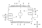
- FIG. 3 is a plan view of a spring contact 10.
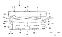
- FIG. 3 is a front view of the spring contact 10.
- FIG. 4 is a sectional view taken along line AA of FIG. 3.
- FIG. 3 is a perspective view showing a state where a pressing force is applied to a spring contact 10.
- FIG. 4 is a bottom view of the spring contact 10.
- FIG. 4 is a plan view in which a spring contact 10 is mounted along a curved shape of a printed circuit board. It is sectional drawing of the spring contact which made the strip
- FIG. It is a perspective view of spring contact 10a concerning a 2nd embodiment. It is a perspective view from another viewpoint of the spring contact 10a. It is a perspective view from another viewpoint of the spring contact 10a. It is a perspective view of spring contact 10b concerning a 3rd embodiment. It is a perspective view from another viewpoint of the spring contact 10b. It is an outline view of an intermediate produced in a manufacturing stage of spring contact 10b. It is explanatory drawing which shows a mode that a 1st plane part is pressed.
- FIG. 9 is an explanatory diagram regarding a case where a bending angle ⁇ is set to a different value.
- the spring contact is for electrically connecting the upper and lower connection objects.
- a spring contact may be a case in which conductive patterns on a printed circuit board are electrically connected to each other.
- one printed board may be a rigid board, and the other printed board may be a flexible board.
- the spring contacts are fixed and joined to the conductor pattern of the rigid board (corresponding to the lower connection target), and the spring contacts are connected to the electrically connected member (the upper connection target such as the conductor pattern of the flexible board). (Equivalent) will be described as an example.
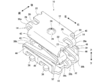
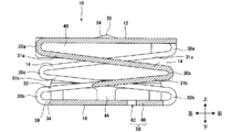
- FIG. 1 is a perspective view of a spring contact 10 according to the first embodiment.
- the spring contact 10 includes a continuous first plane portion 12, a band portion 14 serving as a spring portion, and a second flat portion 16.
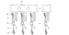
- a long plate-shaped metal strip (hoop material) 18 is divided into portions that become the first flat portion 12, the strip portion 14, and the second flat portion 16.
- the spring contact 10 is formed by performing a cutting process (punching process) so as to obtain a plurality of spring contacts and a bending process or the like of each band-shaped portion 14. Cutting and bending can be performed by pressing.
- the spring contact 10 is separated from the metal strip 18 before or after bending.
- the metal strip 18 is made of a metal such as phosphor bronze, beryllium copper, or brass. Before or after the pressing, a plating layer such as a tin plating layer or a gold plating layer may be formed on the surface of the metal strip 18. In addition to forming the spring contact 10 from the metal strip 18, the spring contact 10 may be formed from a single metal plate.
- each of the upper and lower second plane portions 16 in FIG. 2 corresponds to the first element according to the present invention, and the other corresponds to the first element. This corresponds to the second element according to the present invention.
- the first flat portion 12 is a flat shape having a vertical direction in a thickness direction, and is a portion to be a contact to be pressed by the electrically connected member.
- the first plane portion 12 is formed in a polygonal shape having an even number of sides (a rectangular shape in the present embodiment), and can form a stopper 40 described later.
- the corner of the polygonal shape may be a rounded shape such as an R shape.
- An example of the size when the first flat portion 12 is viewed in plan is about 1.4 ⁇ 1.0 mm, but is not limited to this size.
- the protruding portion 22 is provided on the opposing edge 20 of the first flat portion 12, but the protruding portion 22 may not be formed as necessary.
- a part 23 of the convex part 22 is a part separated from the metal strip 18.
- the first flat portion 12 and the second flat portion 16 are parallel to each other in an initial state where no pressing force is applied to the first flat portion 12.
- a convex portion 24 is provided at the center of the first flat portion 12 to be in contact with the upper connection target. As shown in FIGS. 3 and 4, the convex portion 24 has a mountain shape that is point-symmetric with respect to the vertex 26.
- the convex portion 24 can be formed by pressing at the time of the press working.
- the electric connection member applies a pressing force to the first flat portion 12 by pressing the vertex 26 of the convex portion 24. Since the convex portion 24 is located at the center of the first flat portion 12 and the vertex 26 is located at the center of the first flat portion 12, the pressing force of the electrically connected member is evenly applied to the entire first flat portion 12. .
- the shape of the spring contact 10 is 180 ° rotationally symmetric with respect to an axis passing through the vertex 26 (the center of the first plane portion 12) and orthogonal to the first plane portion 12 (a shape rotated 180 ° from the original shape).
- the first plane portion 12 and each band-shaped portion 14 which are a part thereof are also similarly 180 ° rotationally symmetric.
- the shape of the first flat portion 12 can be viewed as 180 ° symmetric (point symmetry) with respect to the center of the first flat portion 12 when the first flat portion 12 is viewed in plan.
- the pressing force is evenly applied from the first flat portion 12 to the belt portion 14, and the first flat portion 12 can be moved while maintaining parallelism with the second flat portion 16 as described later.
- the size of the convex portion 24 is not limited, but when mounting the spring contact 10, if the first flat portion 12 is sucked by the suction nozzle, the convex portion 24 is made smaller than the suction port of the suction nozzle, The first flat portion 12 can be sucked by the suction nozzle. Note that the convex portion 24 may be omitted as long as the electrically connected member can uniformly press the entire first flat portion 12.
- the band portion 14 is a band-shaped portion formed by bending between the first plane portion 12 and the second plane portion 16, and serves as a spring portion.
- one ends 28 of the two band-shaped portions 14 are respectively connected to left and right end sides 20 of the first flat portion 12.
- the width of the band portion 14 is smaller than 1 / of the width of the edge 20 of the first flat portion 12 so that the band portions 14 do not come into contact with each other.
- the band portion 14 includes two or more bent portions 30a, 30b, and 30c. In this embodiment, three bent portions are formed for each band portion 14 as described above.
- a portion connecting the bent portions 30a, 30b, and 30c is formed in a straight line, and becomes the straight portions 31a and 31b.
- the two band portions 14 are arranged so as to meander from the first plane portion 12 to the second plane portion 16.
- the bent portion 30c has substantially the same horizontal position as the upper and lower bent portions 30a, 30b of the other band-shaped portion 14.
- each of the belt-shaped portions 14 is formed so as to partially overlap when viewed from the front, and meandering using a sufficiently large space between the first flat portion 12 and the second flat portion 16 can be realized. It is easy to have good properties as a spring.
- the two band-shaped portions 14 are arranged with their positions shifted in the front-rear direction, even if they are formed so as to partially overlap each other, it is possible to avoid contact with each other. is there.
- each band 14 is rotationally symmetric with respect to the axis described above by 180 °, and the bending angles of the bent portions 30a, 30b, 30c of each band 14 are also equal.
- the bent portions 30a, 30b, and 30c are bent so that the first flat portion 12 and the straight portion 31a, the straight portion 31a and the straight portion 31b, and the straight portion 31b and the second flat portion 16 have an acute angle.
- the bending angle of each bent portion 30a, 30b, 30c is not limited to the acute angle described above, and the angle may be increased as long as the band portion 14 can function as a spring.
- the angle of each bent portion 30a, 30b, 30c may be 90 ° or the like.
- the pressing force is uniformly applied from the first flat portion 12 to each band-shaped portion 14. Since the strips 14 are rotationally symmetrical by 180 ° as described above, the strips 14 are simultaneously compressed to have the same shape.
- the first flat part 12 moves without being twisted with respect to the second flat part 16, while maintaining the state where the first flat part 12 is parallel to the second flat part 16. Since the strips 14 are arranged so as to have the above-described 180 ° rotational symmetry, the strips 14 can be prevented from being twisted and plastically deformed.
- the bent portions 30a, 30b, 30c are R-shaped. Since the bent portions 30a, 30b, and 30c have an R shape, the band portion 14 can have elasticity, and the band portion 14 can maintain its function as a spring. When the first flat portion 12 is pressed and the pressing force is released, the first flat portion 12 returns to the original position, and the spring contact 10 returns to the original state.
- the bent portions 30a, 30b, and 30c of the band portion 14 include a first bent portion 30a that is continuous with the first flat portion 12, a second bent portion 30b that is continuous with the second flat portion 16, and the first bent portion 30a and the second bent portion 30b. It comprises a third bent portion 30c formed between the bent portion 30b.
- the first bent portion 30a is narrower and narrower than the second bent portion 30b.
- the second bent portion 30b has a notch 32 into which the first bent portion 30a enters. Note that the notch 32 may be slightly formed in the straight portion 30b. As shown in FIG. 6, when the band portion 14 is strongly compressed and elastically deformed, the first bent portion 30 a can enter the notch 32.
- the notch 32 into which the first bent portion 30a enters is formed in the second bent portion 30b, not only the amount of deformation of each bent portion 30a, 30b, 30c can be increased, but also the entire spring contact 10 becomes bulky. Can be prevented, and the stroke when the electrically connected member presses the first flat portion 12 can be lengthened. At this time, the straight portions 31a and 31b bend and contribute to the spring function of the band portion 14. The notch 32 can be omitted if the stroke can be short.
- the bending portions 30a, 30b, and 30c adjust the bending angle of the spring contact 10 in the initial state (the state in which the first flat portion 12 is not pressed) to adjust the size of the electronic device on which the spring contact 10 is mounted.
- the distance from the first flat portion 12 to the second flat portion 16 is adjustable.
- the distance from the first plane part 12 to the second plane part 16 is about 3.0 to 1.0 mm.
- the bending angles of the bent portions 30a, 30b, and 30c may be appropriately adjusted according to the stroke when the electrically connected member presses the first flat portion 12.
- the second flat portion 16 is a portion that is electrically joined to the conductor pattern of the printed board by soldering or the like, and is formed continuously at each end of the two band-shaped portions 14. I have. Specifically, the two second plane portions 16 are planar, and the other end 36 of the band portion 14 is connected to the edge 34 of the second plane portion 16, and the two second plane portions 16 are described later. The part 16 is integrated by the fitting part 58. Since the two second flat portions 16 are flush with each other, the two second flat portions 16 are integrally joined to the conductor pattern.
- the second flat portion 16 has a polygonal shape having an even number of sides (a rectangular shape in the present embodiment), and can form a guide 44 described later. The corner of the polygonal shape may be a rounded shape such as an R shape.
- the second flat portion 16 may be formed by soldering the entire contact surface with the conductor pattern to the conductor pattern, or only the side portion 38 of the contact surface may be soldered to the conductor pattern. Soldering can be performed by an arbitrary method such as a reflow method.
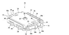
- the first flat portion 12 forms the stopper 40.
- the stopper 40 is a portion of the first flat portion 12 where the side edge 42 (each of the front and rear ends) where the belt-shaped portion 14 is not connected is bent toward the second flat portion 16 toward the bent portions 30b and 30c.
- the stopper 40 is arranged perpendicularly to the first plane portion 12.
- the stoppers 40 are formed at two places so as to face each other in parallel. When the first flat portion 12 is pressed toward the second flat portion 16, the tip of the stopper 40 is brought into contact with the second flat portion 16, thereby preventing the first flat portion 12 from moving more than necessary.
- the stopper 40 prevents the first flat portion 12 from moving too much and the spring contact 10 from being deformed.
- the height of the stopper 40 the movable distance of the first flat portion 12 can be changed. Further, the strength of the spring contact 10 can be increased by arranging the stopper 40 to bend in the vertical direction with respect to the first plane portion 12.
- the second flat portion 16 includes the guide 44.
- the guide 44 is a portion of the second flat portion 16 in which the side edges 46 (front and rear ends) of the second flat portion 16 that are not connected are bent toward the first flat portion 12 toward the bent portions 30a and 30b.
- the guide 44 is arranged perpendicular to the second plane portion 16.
- the guides 44 are formed at two places so as to face each other in parallel.
- the two stoppers 40 move between the guides 44 facing each other.
- the outer surface of the stopper 40 and the inner surface of the guide 44 are surfaces facing each other in the front-rear direction (opposed surface). The positional relationship between the stopper 40 and the guide 44 is determined by sliding the outer surface of the stopper 40 while contacting the inner surface of the guide 44.
- the outer surface of the stopper 40 and the inner surface of the guide 44 are closely opposed to each other, so that the outer surface of the stopper 40 and the inner surface of the guide 44 are always kept parallel to each other. It is possible to prevent relative rotation and the like when viewed from above.
- the height of the guide 44 By appropriately changing the height of the guide 44, the length for guiding the stopper 40 can be changed. Further, the strength of the spring contact 10 can be increased by arranging the guide 44 so as to be bent in the vertical direction with respect to the second plane portion 16.
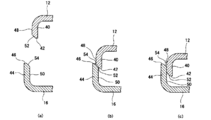
- the inclined surfaces 52 and 54 may be provided on the ends 42 and 46 of the stopper 40 and the guide 44 (FIG. 8A). Even if one of the two stoppers 40 descends so as to lie on the edge 46 of the guide 44, the inclined surface 52 comes into contact with the inclined surface 54 of the guide 44, so that the inner surface of the stopper 40 is inward. The guide 40 descends toward the second flat portion 16 while being guided (FIG. 8B), and the stopper 40 moves on the inner surface side of the guide 44 (FIG. 8C). Even if a slight dimensional error occurs during the formation of the spring contact 10, the outer surface 48 of the stopper 40 can be reliably arranged on the inner surface 50 side of the guide 44 by the inclined surfaces 52 and 54. Note that the inclined surfaces 52 and 54 may be omitted.
- the stopper 40 is provided on the first flat portion 12 and the guide 44 is provided on the second flat portion 16, but the stopper 40 may be provided on the second flat portion 16 and the guide 44 may be provided on the first flat portion 12.
- the number of the stopper 40 and the number of the guides 44 are not limited to two, but may be one.
- the stopper 40 and the guide 44 need not be provided.
- only the stopper 40 may be provided. In this case, it may be provided only on the first flat portion 12, may be provided only on the second flat portion 16, or may be provided on the first flat portion 12 and the second flat portion 16.
- the two second flat portions 16 include fitting portions 58 that are fitted to the opposing side portions 56.
- the fitting portion 58 is formed by, for example, an L-shaped convex portion 60 and a concave portion 62 into which the convex portion 60 is fitted.
- the convex portion 60 enters the concave portion 62, the movement of the second flat portion 16 in a direction orthogonal to the compression direction of the band portion 14 can be restricted. Since the two second plane portions 16 can be prevented from shifting in the plane direction, and the two second plane portions 16 can be kept in an integrated state, the shape of the spring contact 10 can be easily maintained.
- a printed board having the spring contact 10 By electrically connecting the spring contact 10 to the conductor pattern of the printed board with solder or the like, a printed board having the spring contact 10 can be configured. Since the spring contact 10 of the present application has a very small shape as described above, the spring contact 10 can be mounted along the curved shape 66 of the printed board 64 as shown in FIG. The proportion of the mounting area on the printed board 64 can be increased, and the printed board 64 can be mounted at a high density.
- the electronic device of the present embodiment is a device provided with a printed board 64 on which the spring contact 10 is mounted.
- Electronic devices include any devices such as smartphones, tablets, mobile phones, laptop computers, digital cameras, televisions, audio devices, and various remote controls. Further, the electronic device is not limited to a single product, and includes a module that performs a predetermined function such as a car audio system and a car navigation system mounted on an automobile. If the printed circuit board 64 is mounted with high density as described above, the size of the electronic device can be reduced.
- the first plane portion 12 can be moved while maintaining the parallel state with respect to the second plane portion 16, so that the band portion 14 can be prevented from being twisted and plastically deformed.
- the shape of the spring contact 10 can be maintained even if connection and disconnection between the conductor pattern and the electrically connected member are repeated. Therefore, the spring contact 10 can ensure electrical connection and disconnection.
- the spring contact 10 of the present invention can also be used as a proximity sensor or a switch.
- the shape of the first plane portion 12 may be an arbitrary shape such as a polygon including a square or a rectangle, a circle, or an ellipse.
- the shape in a state where the two second plane portions 16 are integrated may be any shape such as a polygon, a circle, and an ellipse.
- the first plane portion 12 and the second plane portion 16 may have different shapes. Further, the shapes of the first plane portion 12 and the second plane portion 16 may have any irregularities on the outer periphery.
- the number of the bent portions 30a, 30b, and 30c of the band portion 14 is three, but the number can be set arbitrarily.
- the band-shaped portion 72 includes two bent portions, that is, a first bent portion 30a and a second bent portion 30b, and further includes a straight portion 73 between the bent portions 30a and 30b. ing.
- the first flat portion 12, the band portion 72, and the second flat portion 16 are formed such that the side view becomes a Z shape.
- the first flat portion 12 may rotate slightly in the flat direction while keeping parallel to the second flat portion 16, but the present invention can be applied to the spring contact 70 having a short stroke.
- the second flat portion 16 is connected to the substrate so as to be slidable in a conductive state with respect to the substrate, whereby the first flat portion 12 can be moved without rotating in the planar direction. Further, the number of bent portions included in one belt-shaped portion may be four or more.
- the number of the band-shaped portions 14 can be set arbitrarily as long as the first flat portion 12 can move while keeping the second flat portion 16 parallel.
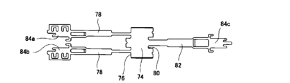
- two strips 78 may be connected to one end 76 of the first flat portion 74, and one strip 82 may be connected to the other end 80.
- the elastic force is adjusted by changing the width of the belt-shaped portions 78 and 82 so that the first flat portion 12 can move while keeping parallel to the second flat portions 84a, 84b and 84c.
- the length direction of the band portion 14 may be oriented in any direction with respect to the first plane portion 12, and the two band portions 14 do not face the above-described 180 ° rotationally symmetric direction, It may face any direction.
- the shape is not limited to the linear shape.
- the space between the bent portions 30a, 30b, 30c may be curved or meandering.
- a belt-like portion may be used in which the bent portions 30a, 30b, and 30c are directly connected to each other and the straight portions 31a and 31b are omitted.
- the first bent portion 30a is formed continuously with the first flat portion 12 and the second bent portion 30b is formed continuously with the second flat portion 16, but the first bent portion 30a is formed continuously with the second flat portion. 16, the second bent portion 30b may be formed continuously with the first flat portion 12.
- fitting portions 58 are provided on the second flat portion 16 in FIG. 7, one fitting portion 88 may be used like the second flat portion 86 in FIG.
- the fitting portions 58 and 88 are not limited to the above-described convex portions 60 and concave portions 62 as long as the position of the second flat portion 12 can be regulated.
- the fitting portion 92 may be formed in a stepped shape to prevent the mutual stepped shape from shifting the position of the second flat portion 90.
- the configuration of the spring contact 10 shown in the above embodiment may be used upside down.
- the second flat portion 16 is on the contact side pressed by the electrically connected member, and the first flat portion 12 is connected to the conductor pattern of the printed board by soldering or the like. Are electrically joined.
- connection of the conductor pattern of the rigid board and the conductor pattern of the flexible board has been described.
- connection of the conductor patterns of the rigid board or the connection of the conductor patterns of the flexible board may be made.
- a spring contact may be bonded to the conductor pattern of the flexible board, and the conductor pattern of the rigid board may press the first plane portion.
- the two objects to be connected by the spring contact are not limited to the connection of the conductor pattern of the printed circuit board, but may be used for the terminal connection of the wire harness. Therefore, the electronic device of the present application is not limited to the electronic device including the printed circuit board on which the spring contact is mounted, but is included in the electronic device by an arbitrary method.
- the spring contact according to the present embodiment is configured such that each end of the band-shaped portion is continuous with the first plane portion and the second plane portion shape, and the first plane portion is connected to the second plane portion via the bent band-shaped portion.
- the band portion is deformed to be compressed.
- the first flat portion can be moved while keeping the first flat portion parallel to the second flat portion, and the belt-like portion can be prevented from being deformed or damaged, and can be prevented from being deformed. Part inclination can also be prevented.
- the strip can be restored to its original shape even after repeated electrical connection and disconnection. Therefore, the shape of the spring contact is maintained, and the spring contact can maintain a desired electrical connection.
- the belt-like portion is formed in a shape that is 180 ° rotationally symmetric with respect to the center of the first plane portion, and two or more bent portions that are 180 ° rotationally symmetric are formed so that the bending angles are equal.
- the plane part and the second plane part can be kept parallel without tilting.
- the notch is formed in the bent portion, the amount of compression of the bent portion can be increased as much as possible, and the height of the entire spring contact can be reduced while maintaining the predetermined amount of compression.
- the stopper and the guide it is possible to more reliably keep the first plane portion and the second plane portion parallel without deforming or breaking the spring contact.
- the fitting portion in the second flat portion, the movement of the second flat portion in the planar direction can be regulated by the fitting portion, so that the shape of the spring contact can be easily maintained.
- the spring contact of this embodiment can be mounted on a printed circuit board at high density, and the printed circuit board can be downsized. Therefore, the electronic device having the spring contact according to the present embodiment can be downsized. Further, the spring contact of the present embodiment has a shorter conduction distance than a conventional one, so that high-speed circuits can transmit and receive signals at high speed.
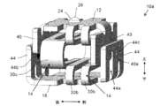
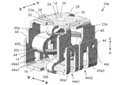
- FIGS. 13 to 15 are perspective views of the spring contact 10a according to the second embodiment viewed from another angle.
- the shape of the spring contact 10a according to the second embodiment also passes through the vertex 26 (the center of the first flat portion 12) and is orthogonal to the first flat portion 12 (the axis extending in the up-down direction).
- the first flat portion 12 and each band-shaped portion 14 as a part thereof are also 180 ° rotationally symmetric.
- One end 28 of each of the two band-shaped portions 14 provided on the spring contact 10a is connected to an end 20 of the first flat portion 12 facing the left and right. Further, a notch extending in the same direction as the direction in which the belt-shaped portion 14 extends is provided at the center in the front-rear direction of the first bent portion 30a and the second bent portion 20b. These notches are provided mainly to balance the stress generated in the band-shaped portion 14 during elastic deformation. For example, if the width of the band-shaped portion 14 is made uniform, the stress becomes higher in the vicinity of the first bent portion 30a and the second bent portion 20b than in the vicinity of the third bent portion 30a. It is possible to reduce such bias of stress.
- the first bent portion 30b can enter the notch formed in the second bent portion 30b.
- the second embodiment does not adopt such a configuration.
- a configuration that allows such entry may be adopted.
- the width of the band-shaped portion 14 is reduced near the first bent portion 30a and the second bent portion 20b as compared with the vicinity of the third bent portion 30a.
- the bias of the stress is similarly reduced.
- two second flat portions 16 portions connected to separate strip portions 14 and correspond to the first and second elements according to the present invention
- the second planar portions 16 are not provided, and the edges of the second planar portions 16 are opposed to each other so as to be close to the left and right, and the lower surfaces thereof are on the same plane.
- a fitting portion may be provided as in the first embodiment.
- the two second plane portions 16 can be used as soldering surfaces when fixing to a connection target using solder.
- each of the front and rear stoppers 40 of the second embodiment is provided with a fitting projection 40a
- each of the front and rear guides 44 is provided with a hole 44a into which the fitting projection 40a is fitted.
- the fitting projection 40a is fitted into the hole 44a, and the relative positional relationship between the first flat portion 12 and the second flat portion 16 is limited by the contact between the fitting projection 40a and the edge of the hole 44a. I am trying to be.
- the horizontal dimension of the hole 44a is constant regardless of the vertical position, and the dimension is slightly larger than the horizontal dimension of the fitting projection 40a.
- the fitting projection 40a and the hole 44a are aligned at the center in the left-right direction. Thereby, the left and right movement of the fitting projection 40a is suppressed by the contact with the left and right edges of the hole 44a, and the displacement of the relative positional relationship between the first plane portion 12 and the second plane portion 16 in the left and right direction is also suppressed. You. Furthermore, the rotation of the fitting projection 40a when viewed from above is also suppressed by the contact between the left and right end surfaces of the fitting projection 40a and the left and right edge surfaces of the hole 44a (a surface whose front-back dimension corresponds to the plate thickness).
- the relative displacement between the first plane portion 12 and the second plane portion 16 in the upward rotation direction is also suppressed.
- the vertical movement of the fitting projection 40a is not hindered unless the upper edge of the hole 44a is contacted.
- a component corresponding to the fitting projection 40a may be provided on the guide 44 side, and a component corresponding to the hole 44a may be provided on the stopper 40 side.
- the maximum distance between the first flat portion 12 and the second flat portion 16 is defined by the fact that the fitting projection 40a comes into contact with (hook) the upper edge of the hole 44a.
- the fitting projection 40a contacts the upper edge of the hole 44a, and
- the spring (spring that expands and contracts up and down) by the band-shaped portion 14 is set to be in a slightly contracted state.
- the first flat portion 12 and the second flat portion 16 are urged in a direction away from each other by the elastic force of the band portion 14.
- the distance between the first plane portion 12 and the second plane portion 16 in the initial state is stabilized at the above-described maximum distance. I can do it.
- the magnitude of the initial load it is also possible to adjust the initial contact force between the connection target and the first flat portion 12 (the contact force when the spring contact 10a starts to deform).
- the magnitude of the initial load and the magnitude of the maximum distance can be appropriately set according to the product specifications and the like.
- the conductive projections 44b projecting toward the outer surface (opposing surface) of the corresponding stopper 40 are provided on the inner surface of each of the front and rear guides 44.
- the conductive protrusions 44b can be formed by pressing the outer surface of the guide 44, as in the case of the protrusions 24.
- the concave portion 44c formed on the outer surface of the guide 44 is formed by the pressing process.
- the conductive protrusions 44b are in contact with the opposing surface of the stopper 40, and thereby each of the guides 44 and the conductive protrusions 44b are brought into contact with each other via the conductive protrusions 44b. It is possible to form a conductive path.
- the conductive path is shorter than the conductive path when the guides 44 and the conductive protrusions 44b are not in contact (a conductive path between the first flat portion and the second flat portion via the strip portion 14).
- the tip of the conductive protrusion 44b be pressed against the outer surface of the stopper 40.
- a component corresponding to the conductive protrusion 44b may be provided on the outer surface of the stopper 40, and may be brought into contact with the inner surface of the guide 40.
- the conductive projections 44b are prevented from contacting the stopper 40, and are brought into contact at a stage where the flat portion 12 has moved downward by a predetermined amount or more.
- the friction between the conductive projection 44b and the outer surface of the stopper 40 is suppressed, and the first plane portion 12 is designed to be easily moved downward as much as possible.
- the outer surface of the stopper 40 and the inner surface of the guide 44 are closely opposed to each other, so that the outer surface of the stopper 40 and the inner surface of the guide 44 are always kept parallel, and the upper surface of the first flat portion 12 and the second flat portion 16
- the point that relative rotation and the like by visual observation can be prevented is the same as in the case of the first embodiment.
- the present embodiment the same applies to a third embodiment described later
- the outer surface of the stopper 40 and the inner surface of the guide 44 are closely opposed to each other. Can be.
- the effect of suppressing the positional shift by the combination of the fitting projection 40a and the hole 44a described above is also effective in the initial state.
- the spring contact 10a of the present embodiment in the initial state even if an unintended external force is applied to the spring contact 10a of the present embodiment in the initial state, deformation, breakage, and the like are suppressed as much as possible.
- the spring contact is often handled in an initial state in which the connection target has not yet contacted the first flat portion 12, and it is important that deformation, breakage, and the like be suppressed even in the initial state.
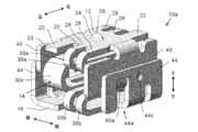
- FIGS. 16 and 17 are perspective views of the spring contact 10b according to the third embodiment viewed from another angle.
- the shape of the spring contact 10b according to the third embodiment also passes through the vertex 26 (the center of the first plane portion 12) and is orthogonal to the first plane portion 12 (the axis extending in the vertical direction).
- the first flat portion 12 and each band-shaped portion 14 as a part thereof are also 180 ° rotationally symmetric.
- the vertical dimension of the spring contact 10b varies from about 0.9 mm (pressed state) to about 1.2 mm (initial state).
- each of the front and rear stoppers 40 is provided with two fitting projections 40a1 and 40a2, and each of the front and rear guides 44 is provided with two holes 44a1 and 44a2.
- the fitting projection 40a1 is provided on the left side of the stopper 40, and the fitting projection 40a2 is provided on the right side of the stopper 40.
- the hole 44a1 is provided at a position of the guide 44 where the fitting protrusion 40a1 is fitted, and the hole 44a2 is provided at a position of the guide 44 where the fitting protrusion 40a2 is fitted.
- fitting projections 40a1 and 40a2 and the holes 44a1 and 44a2 are basically the same as those in the second embodiment.
- the displacement of the relative positional relationship between the first flat portion 12 and the second flat portion 16 in the left-right direction is more effectively suppressed by increasing the number of combinations of fitting protrusions and holes. It is possible.
- a total of four combinations of fitting projections and holes corresponding to each other are arranged so as to be substantially symmetrical in both front and rear and right and left when viewed from above. It is possible to further stabilize the shape in the above.
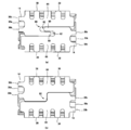
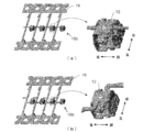
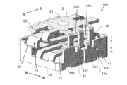
- the spring contact is manufactured from a metal strip (metal plate) cut (punched) so as to obtain a plurality of spring contacts.
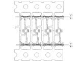
- the state immediately before the spring contact is cut out of the metal strip is in the form shown in FIG. In FIG. 18, an enlarged view of a portion surrounded by a broken line frame is shown on the right side.
- other portions of the metal strip are connected to the front and rear edges of the first flat portion 12 in the spring contact 10b, and the spring contact 10b is obtained by cutting the vicinity of the connection portion.
- a portion 23a of the front and rear ends of the first flat portion 12 is a portion separated from the other portions of the metal strip.
- the part 23a of the end portion is positioned slightly below the outer surface of the first flat portion 12 by bending, so that contact with the connection target (see FIG. 19) is avoided as much as possible. ing.
- the form of the intermediate is not particularly limited as long as a spring contact can be appropriately obtained. For example, as shown in FIG. 18B, other portions of the metal strip are connected to the left and right edges of the first flat portion 12 in the spring contact 10b, and the vicinity of the connection portion is cut to form the spring contact. 10b may be obtained.
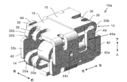
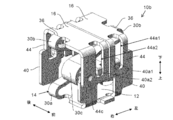
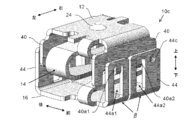
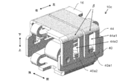
- FIGS. 20 and 21 are perspective views of the spring contact 10c according to the fourth embodiment viewed from another angle.
- the lower side of the two holes 44a1 and 44a2 formed in the front and rear guides 44 is a bent portion between the second plane portion 16 and the front and rear guides 44. It does not extend to the R portion of ⁇ (the curved surface portion formed by bending the metal plate material). Therefore, in the fourth embodiment, no hole is provided in the R portion of the bent portion ⁇ , and the R portions of the bent portion ⁇ are continuously connected at the entire front and rear ends of the second flat portion 16.
- the connection target in the process of mounting the spring contact 10c on the lower connection target, it is possible to solder the range enclosed by the broken line (the range indicated by hatching) shown in FIG. 21 to the connection target. That is, not only the second flat portion 16 but also a wide range of the R portion of the bent portion ⁇ can be soldered to the connection target, and the spring contact 10c can be more securely connected and fixed to the connection target. Further, when the second flat portion 16 is fixed to the connection target by reflow soldering, the surface tension of the solder at the R portion is increased, and it is possible to suppress a situation in which the spring contact 10c rotates unintentionally. .
- the two right and left fitting projections 40a1 and 40a2 are formed by bending a part of the guide 40 outward.
- the bending angle (bending angle ⁇ ) may be set to various values. It is possible.
- FIGS. 22A to 22C shows the spring contact 10c when the bending angle ⁇ is set to a different value.
- the upper side shows an external perspective view of the spring contact 10c
- the lower side shows a cross-sectional view (a cross-sectional view taken along a plane perpendicular to the left-right direction passing through the fitting projection 40a1). I have.
- the bending angle ⁇ in FIG. 22A is approximately 180 °, and the fitting projections 40 a 1 and 40 a 2 are bent so as to be in close contact with the guide 40.
- the protrusion amount ⁇ of the fitting projections 40a1 and 40a2 in the front-rear direction from the guide 40 is approximately equivalent to the plate thickness of the fitting projections 40a1 and 40a2.
- the bending angle ⁇ in FIG. 22B is slightly smaller than the bending angle ⁇ in FIG.
- the protrusion amount ⁇ in FIG. 22B is larger than the protrusion amount ⁇ in FIG. Therefore, in the spring contact 10c shown in FIG. 22B, even when an external force in the front-rear direction is applied to the guide portion 40 as illustrated by the white arrow in FIG.
- the projections 40a1 and 40a2 can be made hard to deviate from the holes 44a1 and 44a2. Thereby, it is possible to make it difficult for the hooks of the fitting projections 40a1 and 40a2 (the hooks on the upper edges of the holes 44a1 and 44a2) to come off.
- the bending angle ⁇ is smaller than that shown in FIG. 22 (B), and the protruding amount ⁇ is correspondingly larger.
- a gap is formed between the guide 44 and the fitting projections 40a1 and 40a2, the gap having a size enough to receive the upper edges of the holes 44a1 and 44a2. Therefore, at least in the initial state, the upper edges of the holes 44a1 and 44a2 of the spring contact 10c are in a state of being fitted between the guide 44 and the fitting protrusions 40a1 and 40a2.
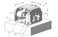
- FIG. 23 is a perspective view of a spring contact 10d according to the fifth embodiment.
- a reinforcing portion 45 is provided so as to be connected to one end of the guide 40 in the left-right direction. More specifically, a portion of the metal plate connected to the left side of the front guide 40 is bent backward by 90 ° to form the left reinforcing portion 45. On the other hand, the metal plate connected to the right side of the rear guide 40 is bent forward by 90 ° to form the right reinforcing portion 45.
- the lower end 45a together with the second flat portion 16 may be soldered to the upper plane of the connection target Ob1.
- the lower end 45a can also be soldered to the connection target Ob1, and unintended deformation of the spring contact 10d and peeling from the connection target Ob1 can be suppressed.
- the lower end portion 45a is in contact with the connection target Ob1, and therefore the deformation such that the upper side of the guide 40 falls backward by the support of the reinforcing portion 45 is prevented.
- a force is generated to press the lower end 45a against the connection target Ob1, and this force acts to prevent the lower end 45a and the connection target Ob1 from being separated from each other by soldering.
- FIG. 25 is a perspective view of a spring contact 10e according to the sixth embodiment.
- FIG. 26 is a cross-sectional view of the spring contact 10e shown in FIG. 25 (a cross-sectional view when the spring contact 10e is cut in a plane that divides the spring contact 10e forward and backward).
- a groove 40x and a claw 44x are provided instead of the fitting projections 40a1, 40a2 and the holes 44a1, 44a2.
- the stopper 40 is provided with two vertically extending grooves 40x arranged side by side.
- the guide 44 is provided with two claw portions 44x corresponding to the two groove portions 40x, respectively.
- the claw portion 44x is bent inward in the front-rear direction from the upper end of the guide 44, and is formed so as to fit into the corresponding groove portion 40x.
- the width (dimension in the left-right direction) of the claw 44x is equal to or slightly smaller than the width of the groove 40x.
- the claw portion 44x is relatively movable vertically in the groove portion 40x.
- the first flat portion 12 can be prevented from being displaced in the left-right direction.
- the claw portion 44x is hooked on the lower edge of the groove portion 40x, the upward movable range of the first flat portion 12 can be restricted.
- a wall portion 49 having a thickness direction in the left-right direction is provided on each of the left and right sides of the spring contact 10e.
- the left wall portion 49 has a rearward portion projecting upward so as to protect the rear band portion 14 from the left side.
- the right wall portion 49 has a forward portion projecting upward so as to protect the front band portion 14 from the right side.
- a predetermined portion (for example, a portion indicated by Q2 in FIG. 25) of the first flat portion 12 comes into contact with an upper end (for example, a portion indicated by Q1 in FIG. 25) of these overhanging portions.
- the downward movable range can be regulated.
- the leftward portion of the front guide 44 is formed as a portion bent 90 degrees to the right from the front end of the left wall portion 49, and the rightward portion is formed from the front end of the right wall portion 49 to the left. It is formed as a part that is bent 90 degrees to the right.
- the leftward portion of the rear guide 44 is formed as a portion bent 90 degrees to the right from the rear end of the left wall portion 49, and the rightward portion of the right wall portion 49 is formed. It is formed as a portion bent 90 degrees to the left from the rear end.
- Each of the leftward and rightward portions of the front guide 44 and the leftward and rightward portions of the front guide 44 are provided with extensions 44z that are bent 90 degrees inward in the front-rear direction from a part of the lower end. Have been.
- the extension part 44z functions as a part of the second plane part 16 in the fourth embodiment.
- One end of the front band portion 14 is connected to the first flat portion 12, while the other end is connected to the upper side of the front portion of the left wall portion 49.
- One end of the rear band portion 14 is connected to the first flat portion 12, while the other end is connected to an upper side of a rearward portion of the right wall 49.
- the spring contact 10e has a lower edge of each of the front and rear guide portions 44 and a lower edge of each of the left and right wall portions 49 (each of which corresponds to a side surface of a metal plate material), and each extension portion 44z has a lower portion.
- these downwardly exposed portions are on the same plane, and this plane (virtual plane) is parallel to the first plane portion 12.
- the spring contact 10e of the present embodiment can easily adjust the vertical dimension in accordance with various circumstances by providing a padding (addition of a plate material element) under each guide portion 44 and each wall portion 49. It is.
- FIG. 27 shows a spring contact 10e1 adjusted to have a larger vertical dimension than the spring contact 10e shown in FIG.
- the elements between the dashed lines Y1 and Y2 shown in FIG. 27 are overlaid, and the dimension in the vertical direction is increased by that amount.
- the metal plate for manufacturing the original spring contact 10e may be overlaid. More specifically, a colored plate portion (a portion between the broken line Y1 and the broken line Y2 after manufacturing) may be overlaid on the metal plate material shown in FIG. Thereby, the spring contact 10e1 after the dimension adjustment can be easily manufactured without changing the basic manufacturing process.
- the spring contact according to each of the above-described embodiments is a spring contact that electrically connects upper and lower connection targets, has a first flat portion 12, and has a connection portion connected to the upper connection target, At least two strips 14 formed as springs, one end of which is formed to be continuous with the end of the first flat part 12 and provided with two or more bent parts by bending, and the other end of each of the strips 14 And a base portion formed continuously and connected to a lower connection target. Further, when the connecting portion is pressed downward, each of the belt-shaped portions 14 receives the load of the pressing uniformly, and is elastically deformed so that the connecting portion moves downward in parallel.
- connection portion having the first flat portion 12 and the connection target can be further stabilized while the movement of the first flat portion 12 is not limited by the plate width of the spring. It is also possible to maintain the parallel of the flat portions (the first flat portion 12 and the second flat portion 16).
- the second flat portion 16 of the first to fifth embodiments, and the guide 44 and the wall portion 49 of the sixth embodiment can be regarded as one form of the base portion according to the present invention.
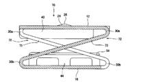
- connection part does not move in parallel, the contact between the connection part and the connection target becomes unstable, or friction occurs between the contact and the connection target every time the spring expands and contracts, which causes factors such as wear. Or there is a risk of In order to make such a phenomenon easier to understand, the second connection target Ob2 (the substrate facing downward) is moved downward with respect to the spring contact with the second flat portion 16 connected and fixed to one connection target Ob1.
- FIG. 19 schematically shows how the connection portion is pressed.
- FIG. 19 shows that when the connection target Ob2 moves downward in the state shown in FIG. 19A, the connection part is pressed downward and the state shown in FIG. 19B is obtained.
- the connecting portion 12 moves downward in parallel, and the same applies to a case where the first flat portion 12 is not provided with the convex portion 24.
- friction may be generated particularly between the vicinity of the apex 26 of the projection and the connection target Ob2.
- the moving direction (vertical direction) of the flat portion is orthogonal to the plate width direction (front-back direction) of the spring, and the movement of the flat portion is not limited by the plate width of the spring.
- first plane portion 12 and the second plane portion 16 in each embodiment can not only maintain the parallelism as described above, but also prevent the relative rotation when viewed from above. Therefore, a situation in which the rotation causes friction between the vicinity of the vertex 26 of the convex portion and the connection target Ob2 is also avoided.
- the spring contact according to each embodiment is taken out of the embossed tape (packaging material) or the like by sucking the first flat portion 12 using a suction nozzle (suction nozzle), the suction nozzle is lightly moved to the first flat portion 12. If the first flat portion 12 rotates in such a manner when pressed, there is a possibility that the suction to the suction nozzle may be hindered.
- the second flat portion 16 causes such rotation. Then, there is a possibility that the fixing position of the spring contact in the connection target Ob1 is shifted. If the relative rotation of the first flat portion 12 and the second flat portion 16 as viewed from above is suppressed, such a problem can be solved.
- each of the band-shaped portions 14 is elastically deformed while pressing against the other one of the first flat portion 12 and the second flat portion 16 while suppressing the tilting of the flat portions. It can.
- FIG. 5 a view from the front perspective
- the first flat portion 12 convex portion 24
- the first flat portion 12 tilts to the left or right (that is, the rotational motion is reduced). It is easy to move downward.
- this strip 14 is elastically deformed while acting to suppress the movement of the other strip 14 in which the tilting occurs. It is possible to move the first plane portion 12 downward while maintaining the parallelism as much as possible.
- the two band-shaped portions 14 are formed such that one is continuous with the left side edge of the first flat portion 12 and the other is continuous with the right side edge of the first flat portion 12. .
- Each of the two belt-like portions 14 is formed so as to be shifted in the front-rear direction and partially overlap when viewed from the front. Therefore, it is possible to arrange each of the band-shaped portions 14 using a sufficiently large space between the first plane portion 12 and the second plane portion 16 when viewed from the front, and to avoid contact between the band-shaped portions 14. It is possible.
- Each of the two band-shaped portions 14 is rotationally symmetric with respect to an axis extending in the vertical direction through the center of the first plane portion 12 (an axis orthogonal to the first plane portion 12). Thereby, it is possible to minimize the deviation of the positions and characteristics of the band-shaped portions 14 as much as possible, and each band-shaped portion 14 receives the pressing load of the flat portion evenly, so that the elasticity is maintained so that the flat portions are maintained in parallel. The effect of deformation can be obtained more reliably and easily. Further, since the convex portion 24 for contacting the connection target is provided at the center of the first flat portion 12, it is easy to press the center of the first flat portion 12 on the upper connection target.
- the front and rear edges of the first flat portion 12 are bent downward to form the stopper 40 (first bent portion), and the front and rear edges of the second flat portion 16 are formed.
- a guide 44 (second bent portion) is formed by bending upward. Then, the opposing surfaces facing the front and rear of the stopper 40 and the guide 44 are brought close to each other, so that the relative positional relationship between the first plane portion 12 and the second plane portion 16 is limited by the contact between the opposing surfaces. I have.
- the first bent portion is formed by bending only one of the front sides and the rear side of the first flat portion 12 downward, and the second bent portion is formed on one of the front side and the rear side of the second flat portion 16. Only the end side may be bent upward.
- the spring contact of each embodiment is formed by a forming method including a step of bending a metal strip (metal plate).
- a metal plate metal plate
- one end of a component of the first plane portion 12 is connected in sequence with a component of one of the band portions 14 and a first element which is a part of a component of the second plane portion 16, At the other end of the component of the portion 12, the component of the other band portion 14 and the second component, which is the remaining component of the component of the second flat portion 16, are sequentially connected.
- the first element is connected in order from the first element to the one band-shaped part 14, the first plane part 12, the other band-shaped part 14, and the second element without the need for bonding or the like.
- the state can be realized, and it is possible to prevent the quality of the band-shaped portion 14 largely related to the spring performance from being deteriorated by adhesion or the like.
- the first element and the second element have a fitting structure in which one side can be fitted to the other side.
- the above-described forming method includes the fitting step. Therefore, it is possible to prevent the first element and the second element from being displaced in the plane direction, and to easily maintain the shape of the spring contact.
Abstract
The present invention provides a spring contact that allows for more stable contact between a connection part having a planar portion and a component to be connected in such a way that movement of the planar portion is not restricted due to the plate width of the spring. Provided is a spring contact for electrically connecting upper and lower components to be connected, the spring contact comprising: a connection part having a first planar portion and to be connected to the upper component; at least two strip-shaped parts with one end continuing to the edge of the first planar portion, each strip-shaped part being bent and formed as a spring having two or more bent portions; and a base part to be connected to the lower component and formed so as to be continuous to the other end of each strip-shaped part. When the connection part is pressed downward, the strip-shaped parts receive the pressing load uniformly and elastically deform so that the connection part translates downward.
Description
本発明は、接続対象同士を電気接続するバネコンタクト、およびバネコンタクトの形成方法に関する。
The present invention relates to a spring contact for electrically connecting objects to be connected and a method for forming the spring contact.
従来、プリント基板などの配線に実装されるコンタクトは、プリント基板の配線とバッテリーの端子などを接続するために用いられている。具体的には、基板の端子にコンタクトを実装しておき、コンタクトを介して他方の基板の端子を接地させて両端子の導通を確保する。たとえば下記の特許文献1には、板バネ材を渦巻き状にしたコイルバネ部を備えたコンタクトが開示されている。特許文献1のコンタクト(圧接コネクタ)は、長尺な板バネ材を渦巻き状に巻き、その両端を折り曲げて両端部に平面な接点を形成している。
Conventionally, a contact mounted on a wiring of a printed circuit board or the like is used to connect a wiring of the printed circuit board to a terminal of a battery. Specifically, a contact is mounted on a terminal of the substrate, and the terminal of the other substrate is grounded via the contact to ensure conduction between the two terminals. For example, Patent Document 1 below discloses a contact provided with a coil spring portion in which a leaf spring material is formed into a spiral shape. The contact (press-connecting connector) of Patent Document 1 is formed by winding a long plate spring material in a spiral shape, and bending both ends thereof to form a flat contact at both ends.
しかし、特許文献1のコンタクトはバネ部を渦巻き状にし、らせんの両端に形成した平面部を押さえつけることにより、コイルバネ部を圧縮させるようにしているため、所定の圧縮量を得るために板バネ材の板幅を狭くし、板バネ材の渦巻きの巻き数を増やして所定の圧縮量を得たりする場合には、圧縮時にバネ部が傾斜しながら上下動する虞がある。
However, in the contact disclosed in Patent Document 1, the coil portion is compressed by pressing the flat portions formed on both ends of the spiral by pressing the spring portion into a spiral shape. When the predetermined width of compression is obtained by reducing the width of the plate and increasing the number of spirals of the leaf spring material, the spring portion may move up and down while being inclined during compression.
そこで、特許文献1では、二重らせん構造にすることにより倒れによる導通不良を低減させるようしているが、接点となる上部の平面部を重ね合わす構造となっているため、コンタクトでは、嵩高になってしまうし、コイルバネ部は板バネ材の板幅方向に上下動するため、平面部の圧縮時の移動量は、板バネ材の幅で規制されてしまうので、コンタクト全体が大きくなりすぎることなく所定の圧縮量を得るためには、板バネ材の板幅を狭くしなければならない。しかしこの場合には、バネの板幅が制限されてしまい、所望のバネ特性が得られなくなる虞がある。
Therefore, in Patent Document 1, a double spiral structure is used to reduce conduction failure due to falling. However, since the upper flat portion serving as a contact is overlapped, the contact is bulky. In addition, since the coil spring part moves up and down in the plate width direction of the leaf spring material, the amount of movement of the flat part during compression is regulated by the width of the leaf spring material, so that the entire contact becomes too large. In order to obtain a predetermined amount of compression, the width of the leaf spring material must be reduced. However, in this case, the plate width of the spring is limited, and there is a possibility that desired spring characteristics cannot be obtained.
圧縮時にコイルバネ部が傾斜しやすい状態で電気的な接続と切断を繰り返すと、コイルバネ部が変形して元の状態へ戻らなくなることによって所定の上下動ができなくなり、電気接続できなくなる虞があるし、結果的に破損する虞がある。
If electrical connection and disconnection are repeated in a state where the coil spring portion is easily inclined during compression, the coil spring portion is deformed and does not return to the original state, so that predetermined vertical movement cannot be performed, and there is a possibility that electrical connection may not be possible. As a result, there is a risk of damage.
上述したコンタクトによれば、初期状態においては両端の平面部同士が平行に形成されていたとしても、バネが伸縮する際に平面部が傾き易い。平面部が傾く場合には、例えば、平面部と接続対象の接触が不安定となったり、バネが伸縮する度にコンタクトと接続対象の間に摩擦が生じ、摩耗等の要因となったりする虞がある。また、平面部の移動方向とバネの板幅方向が一致する場合のように、平面部の移動がバネの板幅によって制限される場合は、コンタクトのコンパクト化が難しくなったり、所望のバネ特性が得られなくなったりする虞がある。
According to the above-described contact, even when the flat portions at both ends are formed in parallel in the initial state, the flat portions are easily inclined when the spring expands and contracts. When the flat portion is inclined, for example, the contact between the flat portion and the connection target becomes unstable, or friction occurs between the contact and the connection target every time the spring expands or contracts, which may cause wear or the like. There is. Further, when the movement of the flat portion is limited by the width of the spring, such as when the direction of movement of the flat portion matches the width direction of the spring, it is difficult to reduce the size of the contact, or to achieve a desired spring characteristic. May not be obtained.
本発明は上述した問題に鑑み、平面部の移動がバネの板幅によって制限されないようにしつつ、平面部を有する接続部と接続対象の接触をより安定させることが可能となるバネコンタクト、当該バネコンタクトの形成方法、および当該バネコンタクトを備えたプリント基板および電子機器の提供を目的とする。
The present invention has been made in view of the above-described problems, and has a spring contact and a spring that can stabilize contact between a connection portion having a flat portion and a connection target while preventing movement of the flat portion from being limited by the plate width of the spring. An object of the present invention is to provide a method for forming a contact, and a printed circuit board and an electronic device provided with the spring contact.
本発明のバネコンタクトは、上下それぞれの接続対象を電気的に接続するバネコンタクトであって、第1平面部を有し、上側の前記接続対象に接続される接続部と、第1平面部の端辺に一端が連続するように形成され、折り曲げによって二箇所以上の屈曲部を設けたバネとして形成された少なくとも二つの帯状部と、前記帯状部それぞれの他端に連続して形成され、下側の前記接続対象に接続されるベース部と、を備え、前記帯状部それぞれは、前記接続部が下方に向けて押圧された際、当該押圧の荷重を均等に受けて、当該接続部が下方へ平行移動するように弾性変形する構成とする。本構成によれば、平面部の移動がバネの板幅によって制限されないようにしつつ、平面部を有する接続部と接続対象の接触をより安定させることが可能となる。
The spring contact of the present invention is a spring contact that electrically connects upper and lower connection targets, has a first flat portion, and includes a connection portion connected to the upper connection target and a first flat portion. One end is formed to be continuous with the end side, at least two band-shaped portions formed as springs provided with two or more bent portions by bending, and formed continuously at the other end of each of the band-shaped portions, And a base portion connected to the connection object on the side, wherein each of the band-shaped portions receives a load of the pressing evenly when the connection portion is pressed downward, and the connection portion is moved downward. And elastically deform so as to move in parallel. According to this configuration, it is possible to further stabilize the contact between the connection portion having the flat portion and the connection target while preventing the movement of the flat portion from being limited by the plate width of the spring.
上記構成としてより具体的には、二つの前記帯状部は、一方が第1平面部の左側の端辺に連続するように形成され、他方が第1平面部の右側の端辺に連続するように形成されており、二つの前記帯状部それぞれは、前後方向へ位置をずらし、前方視により一部が重なるように形成された構成としてもよい。
More specifically, as the above configuration, the two band-shaped portions are formed such that one is continuous with the left side edge of the first plane portion, and the other is continuous with the right side edge of the first plane portion. The two band-shaped portions may be formed so as to be displaced in the front-rear direction and to partially overlap each other when viewed from the front.
上記構成としてより具体的には、二つの前記帯状部それぞれは、第1平面部の略中央部を通って上下方向に伸びる軸を基準として、180度回転対称である構成としてもよい。また上記構成としてより具体的には、第1平面部の略中央部に、上側の前記接続対象を接触させる凸部を設けた構成としてもよい。また上記構成としてより具体的には、前記ベース部は、第1平面部に対して平行であり、下側の前記接続対象に接続される第2平面部を有する構成としてもよい。
More specifically, as the above-described configuration, each of the two band-shaped portions may be configured to be 180-degree rotationally symmetric with respect to an axis extending vertically through a substantially central portion of the first flat portion. More specifically, the above-described configuration may be configured such that a convex portion for contacting the upper connection target is provided substantially at the center of the first plane portion. More specifically, as the above configuration, the base portion may be configured to have a second flat portion parallel to the first flat portion and connected to the lower connection target.
上記構成としてより具体的には、第1平面部の前側または後側の端辺を下方に折り曲げて第1折り曲げ部が形成され、第2平面部の前側または後側の端辺を上方に折り曲げて第2折り曲げ部が形成され、第1折り曲げ部および第2折り曲げ部の前後に対向する対向面同士を近接させ、第1平面部と第2平面部の相対的な位置関係が、当該対向面同士の接触により制限されるようにした構成としてもよい。
More specifically, as the above configuration, the front side or the rear side of the first flat portion is bent downward to form a first bent portion, and the front side or the rear side edge of the second flat portion is bent upward. A second bent portion is formed, and the opposing surfaces facing the front and back of the first bent portion and the second bent portion are brought close to each other, and the relative positional relationship between the first flat portion and the second flat portion is determined by the opposing surface. It may be configured to be restricted by contact between them.
上記構成としてより具体的には、第1折り曲げ部および第2折り曲げ部の一方に嵌め込み用突起を設けるとともに他方に孔を設け、前記嵌め込み用突起を前記孔に嵌め込んで、第1平面部と第2平面部の相対的な位置関係が、当該嵌め込み用突起と当該孔の縁との接触により制限されるようにした構成としてもよい。
More specifically, as the above-described configuration, one of the first bent portion and the second bent portion is provided with a fitting projection and the other is provided with a hole, and the fitting projection is fitted into the hole to form a first flat portion. The relative positional relationship of the second flat portion may be limited by contact between the fitting protrusion and the edge of the hole.
上記構成としてより具体的には、前記嵌め込み用突起が前記孔の縁に接触することにより、前記押圧がなされていない初期状態における第1平面部と第2平面部の距離が規定され、当該初期状態において、前記帯状部の弾性力により第1平面部と第2平面部が互いに離れる方向へ付勢される構成としてもよい。
More specifically, the distance between the first flat portion and the second flat portion in the initial state where the pressing is not performed is defined by the fitting projection contacting the edge of the hole, and In the state, the first flat portion and the second flat portion may be urged in a direction away from each other by the elastic force of the strip portion.
上記構成としてより具体的には、第1折り曲げ部および第2折り曲げ部の一方に、他方の前記対向面に向けて突出した導電用突起を設け、前記導電用突起が当該対向面に接触することにより、第1平面部と第2平面部の間の導電経路が短くなる構成としてもよい。
More specifically, as the above configuration, one of the first bent portion and the second bent portion is provided with a conductive protrusion protruding toward the other opposing surface, and the conductive protrusion contacts the opposing surface. Thereby, the conductive path between the first plane portion and the second plane portion may be shortened.
上記構成としてより具体的には、第1折り曲げ部の下端と第2平面部との接触、または、第2折り曲げ部の上端と第1平面部との接触により、第1平面部と第2平面部の相対的な位置関係が制限される構成としてもよい。
More specifically, the first flat portion and the second flat portion are formed by contact between the lower end of the first bent portion and the second flat portion or between the upper end of the second bent portion and the first flat portion. The configuration may be such that the relative positional relationship between the units is limited.
上記構成としてより具体的には、第1折り曲げ部として、第1平面部の前側の端辺を下方に折り曲げた部分と、第1平面部の後側の端辺を下方に折り曲げた部分のそれぞれが形成され、第2折り曲げ部として、第2平面部の前側の端辺を上方に折り曲げた部分と、第2平面部の後側の端辺を上方に折り曲げた部分のそれぞれが形成された構成としてもよい。
More specifically, as the above-described configuration, as the first bent portion, a portion where the front side edge of the first plane portion is bent downward, and a portion where the rear side edge of the first plane portion is bent downward, respectively. Is formed, and a second bent portion is formed by forming a portion obtained by bending a front edge of the second flat portion upward and a portion obtained by bending a rear edge of the second flat portion upward. It may be.
上記構成としてより具体的には、前記帯状部それぞれの前記屈曲部として、第1屈曲部と、第1屈曲部よりも幅が広く、第1屈曲部が入り込む切り欠きを有する第2屈曲部と、第1屈曲部と第2屈曲部との間に位置する第3屈曲部と、を有する構成としてもよい。
More specifically, as the above-described configuration, as the bending portion of each of the band-shaped portions, a first bending portion, a second bending portion having a width wider than the first bending portion and having a cutout into which the first bending portion enters. And a third bent portion located between the first bent portion and the second bent portion.
上記構成としてより具体的には、第1平面部の前側または後側の端辺を下方に折り曲げて形成した第1折り曲げ部、または、第2平面部の前側または後側の端辺を上方に折り曲げて形成した第2折り曲げ部を有し、第1折り曲げ部の下端と第2平面部との接触、または、第2折り曲げ部の上端と第1平面部との接触により、第1平面部と第2平面部の相対的な位置関係が制限される構成としてもよい。
More specifically, as the above configuration, the first bent portion formed by bending the front or rear edge of the first flat portion downward, or the front or rear edge of the second flat portion upward. A second bent portion formed by bending the first flat portion by contact between the lower end of the first bent portion and the second flat portion, or by contact between the upper end of the second bent portion and the first flat portion; The configuration may be such that the relative positional relationship of the second plane portion is limited.
本発明に係るバネコンタクトの形成方法は、金属板材の折り曲げ工程を含む上記構成のバネコンタクトの形成方法であって、前記金属板材は、第1平面部の構成要素の一端に、一方の前記帯状部の構成要素と第2平面部の構成要素の一部である第1要素が順に連接し、第1平面部の構成要素の他端に、他方の前記帯状部の構成要素と第2平面部の構成要素の残りの部分である第2要素が順に連接している方法とする。また当該方法としてより具体的には、第1要素と第2要素は、一方側の他方側への嵌合を可能とした嵌合部を有し、当該嵌合の工程を含む方法としてもよい。
The method for forming a spring contact according to the present invention is a method for forming a spring contact having the above-described configuration including a step of bending a metal plate material, wherein the metal plate material is provided at one end of a component of a first flat portion, and at one end of the band shape. The component of the part and the first element, which is a part of the component of the second flat part, are sequentially connected, and the other end of the component of the first flat part is connected to the other component of the band-shaped part and the second flat part. Is a method in which the second element, which is the remaining part of the constituent element, is sequentially connected. More specifically, as the method, the first element and the second element may have a fitting portion that allows fitting of one side to the other side, and may include a step of the fitting. .
本発明に係るバネコンタクトによれば、平面部の移動がバネの板幅によって制限されないようにしつつ、平面部を有する接続部と接続対象の接触をより安定させることが可能となる。
According to the spring contact according to the present invention, it is possible to further stabilize the contact between the connection portion having the flat portion and the connection target while preventing the movement of the flat portion from being limited by the plate width of the spring.
本発明の実施形態に係るバネコンタクト、バネコンタクトの形成方法、バネコンタクトを備えたプリント基板および電子機器について、各実施形態を例に挙げ、図面を使用して以下に説明する。以下の説明における上下、左右、および前後の各方向(互いに直交する方向)は、図1等に示すとおりである。
バ ネ A spring contact, a method of forming a spring contact, a printed circuit board provided with a spring contact, and an electronic device according to an embodiment of the present invention will be described below with reference to the drawings, taking each embodiment as an example. In the following description, up, down, left, right, front and rear directions (directions orthogonal to each other) are as shown in FIG.
バネコンタクトは、上下2つの接続対象を電気的に接続するものである。たとえばバネコンタクトは、プリント基板の導体パターン同士を電気的に接続する場合が挙げられる。この場合、一方のプリント基板がリジッド基板、他方のプリント基板がフレキシブル基板となり得る。以下、バネコンタクトがリジッド基板の導体パターン(下側の接続対象に相当する)に固定された状態で接合され、バネコンタクトがフレキシブル基板の導体パターンなどの被電気的接続部材(上側の接続対象に相当する)で押圧される場合を例にして説明する。
The spring contact is for electrically connecting the upper and lower connection objects. For example, a spring contact may be a case in which conductive patterns on a printed circuit board are electrically connected to each other. In this case, one printed board may be a rigid board, and the other printed board may be a flexible board. Hereinafter, the spring contacts are fixed and joined to the conductor pattern of the rigid board (corresponding to the lower connection target), and the spring contacts are connected to the electrically connected member (the upper connection target such as the conductor pattern of the flexible board). (Equivalent) will be described as an example.
1.第1実施形態
まず本発明の第1実施形態について説明する。図1は、第1実施形態に係るバネコンタクト10の斜視図である。バネコンタクト10は、一続きに形成された第1平面部12、バネ部となる帯状部14、第2平面部16を備えている。それらを一続きに形成するために、図2に示すように、長尺板状の金属条材(フープ材)18を第1平面部12、帯状部14および第2平面部16となる部分を有する複数のバネコンタクトが得られるように切断加工(打ち抜き加工)し、各帯状部14の曲げ加工等を行うことによりバネコンタクト10を形成している。切断加工および曲げ加工はプレス加工によって行うことができる。バネコンタクト10は曲げ加工の前または後で金属条材18から切り離される。金属条材18はリン青銅、ベリリウム銅、黄銅などの金属から成る。プレス加工の前または後で金属条材18の表面に錫メッキ層または金メッキ層などのメッキ層を形成しても良い。金属条材18からバネコンタクト10を形成する以外に、枚葉の金属板からバネコンタクト10を形成しても良い。なお図2での上下に示される第2平面部16それぞれ(図7での上下に示される第2平面部16それぞれも同様)は、一方が本発明に係る第1要素に相当し、他方が本発明に係る第2要素に相当する。 1. First Embodiment First, a first embodiment of the present invention will be described. FIG. 1 is a perspective view of aspring contact 10 according to the first embodiment. The spring contact 10 includes a continuous first plane portion 12, a band portion 14 serving as a spring portion, and a second flat portion 16. In order to form them continuously, as shown in FIG. 2, a long plate-shaped metal strip (hoop material) 18 is divided into portions that become the first flat portion 12, the strip portion 14, and the second flat portion 16. The spring contact 10 is formed by performing a cutting process (punching process) so as to obtain a plurality of spring contacts and a bending process or the like of each band-shaped portion 14. Cutting and bending can be performed by pressing. The spring contact 10 is separated from the metal strip 18 before or after bending. The metal strip 18 is made of a metal such as phosphor bronze, beryllium copper, or brass. Before or after the pressing, a plating layer such as a tin plating layer or a gold plating layer may be formed on the surface of the metal strip 18. In addition to forming the spring contact 10 from the metal strip 18, the spring contact 10 may be formed from a single metal plate. In addition, each of the upper and lower second plane portions 16 in FIG. 2 (the same applies to the upper and lower second plane portions 16 in FIG. 7), one corresponds to the first element according to the present invention, and the other corresponds to the first element. This corresponds to the second element according to the present invention.
まず本発明の第1実施形態について説明する。図1は、第1実施形態に係るバネコンタクト10の斜視図である。バネコンタクト10は、一続きに形成された第1平面部12、バネ部となる帯状部14、第2平面部16を備えている。それらを一続きに形成するために、図2に示すように、長尺板状の金属条材(フープ材)18を第1平面部12、帯状部14および第2平面部16となる部分を有する複数のバネコンタクトが得られるように切断加工(打ち抜き加工)し、各帯状部14の曲げ加工等を行うことによりバネコンタクト10を形成している。切断加工および曲げ加工はプレス加工によって行うことができる。バネコンタクト10は曲げ加工の前または後で金属条材18から切り離される。金属条材18はリン青銅、ベリリウム銅、黄銅などの金属から成る。プレス加工の前または後で金属条材18の表面に錫メッキ層または金メッキ層などのメッキ層を形成しても良い。金属条材18からバネコンタクト10を形成する以外に、枚葉の金属板からバネコンタクト10を形成しても良い。なお図2での上下に示される第2平面部16それぞれ(図7での上下に示される第2平面部16それぞれも同様)は、一方が本発明に係る第1要素に相当し、他方が本発明に係る第2要素に相当する。 1. First Embodiment First, a first embodiment of the present invention will be described. FIG. 1 is a perspective view of a
図3の平面図に示すように、第1平面部12は、上下方向を厚み方向とする平面状になっており、被電気的接続部材が押圧する接点になる部分である。第1平面部12は偶数の辺を有する多角形状(本実施形態では矩形状)に形成されており、後述するストッパ40を形成することができる。多角形状の角はR形状などの丸められた形状であっても良い。第1平面部12を平面視した場合の大きさの一例として約1.4×1.0mmが挙げられるが、この大きさに限定されない。また、本実施形態では、第1平面部12の対向する端辺20に凸部22を設けているが、必要に応じてこの凸部22は形成しなくても良い。なお、凸部22の一部23が金属条材18から切り離された部分である。図4に示すように、第1平面部12に押圧力がかかっていない初期状態で第1平面部12と第2平面部16は平行になっている。
As shown in the plan view of FIG. 3, the first flat portion 12 is a flat shape having a vertical direction in a thickness direction, and is a portion to be a contact to be pressed by the electrically connected member. The first plane portion 12 is formed in a polygonal shape having an even number of sides (a rectangular shape in the present embodiment), and can form a stopper 40 described later. The corner of the polygonal shape may be a rounded shape such as an R shape. An example of the size when the first flat portion 12 is viewed in plan is about 1.4 × 1.0 mm, but is not limited to this size. Further, in the present embodiment, the protruding portion 22 is provided on the opposing edge 20 of the first flat portion 12, but the protruding portion 22 may not be formed as necessary. In addition, a part 23 of the convex part 22 is a part separated from the metal strip 18. As shown in FIG. 4, the first flat portion 12 and the second flat portion 16 are parallel to each other in an initial state where no pressing force is applied to the first flat portion 12.
第1平面部12の中心に上側の接続対象と接触する凸部24が設けられている。凸部24は図3、図4に示すように、頂点26に対して点対称になった山形になっている。凸部24は上記プレス加工時に押圧加工することで形成できる。被電気的接続部材は凸部24の頂点26を押圧することで、第1平面部12に押圧力を加える。凸部24が第1平面部12の中央部分にあり、その頂点26が第1平面部12の中心にあるので、被電気的接続部材の押圧力が第1平面部12の全体へ均等にかけられる。なお、バネコンタクト10の形状は、頂点26(第1平面部12の中心)を通り、第1平面部12と直交する軸を基準として180°回転対称(元の形状と180°回転させた形状が同一)であり、その一部である第1平面部12や各帯状部14についても同様に180°回転対称となっている。第1平面部12の形状は、第1平面部12を平面視して第1平面部12の中心に対して180°対称(点対称)であると見ることもできる。第1平面部12から帯状部14へ均等に押圧力がかかり、後述するように第1平面部12が第2平面部16に対して平行を維持しながら移動できる。
凸 A convex portion 24 is provided at the center of the first flat portion 12 to be in contact with the upper connection target. As shown in FIGS. 3 and 4, the convex portion 24 has a mountain shape that is point-symmetric with respect to the vertex 26. The convex portion 24 can be formed by pressing at the time of the press working. The electric connection member applies a pressing force to the first flat portion 12 by pressing the vertex 26 of the convex portion 24. Since the convex portion 24 is located at the center of the first flat portion 12 and the vertex 26 is located at the center of the first flat portion 12, the pressing force of the electrically connected member is evenly applied to the entire first flat portion 12. . Note that the shape of the spring contact 10 is 180 ° rotationally symmetric with respect to an axis passing through the vertex 26 (the center of the first plane portion 12) and orthogonal to the first plane portion 12 (a shape rotated 180 ° from the original shape). Are the same), and the first plane portion 12 and each band-shaped portion 14 which are a part thereof are also similarly 180 ° rotationally symmetric. The shape of the first flat portion 12 can be viewed as 180 ° symmetric (point symmetry) with respect to the center of the first flat portion 12 when the first flat portion 12 is viewed in plan. The pressing force is evenly applied from the first flat portion 12 to the belt portion 14, and the first flat portion 12 can be moved while maintaining parallelism with the second flat portion 16 as described later.
凸部24の大きさは限定されないが、バネコンタクト10を実装するときに、吸引ノズルで第1平面部12を吸引するのであれば、吸引ノズルの吸引口よりも凸部24を小さくして、吸引ノズルで第1平面部12を吸引できるようにする。なお、被電気的接続部材が第1平面部12の全体に対して均等に押圧できるのであれば、凸部24を省略しても良い。
The size of the convex portion 24 is not limited, but when mounting the spring contact 10, if the first flat portion 12 is sucked by the suction nozzle, the convex portion 24 is made smaller than the suction port of the suction nozzle, The first flat portion 12 can be sucked by the suction nozzle. Note that the convex portion 24 may be omitted as long as the electrically connected member can uniformly press the entire first flat portion 12.
図1、図2、図5に示すように、帯状部14は第1平面部12と第2平面部16の間に屈曲して形成された帯状になった部分であり、バネ部となる。また図1に示すように、二つの帯状部14の一端28は、第1平面部12の左右に対向する端辺20にそれぞれ繋がっている。帯状部14は第1平面部12の端辺20の幅の1/2よりも狭い幅になっており、帯状部14同士が接触しないようになっている。帯状部14は2以上の屈曲部30a、30b、30cを備えており、本実施形態ではこのように、一つの帯状部14ごとに3個の屈曲部が形成されている。また、帯状部14は、屈曲部30a、30b、30c同士を結ぶ部分は直線状に形成しており、直線部31a、31bとなる。図4、図5に示すように、前方視により、二つの帯状部14は第1平面部12から第2平面部16まで概ね蛇行するように配置されており、一方の帯状部14の中央の屈曲部30cは、他方の帯状部14の上下の屈曲部30a、30bと左右方向位置がほぼ同じである。このように各帯状部14は、前方視により一部が重なるように形成され、第1平面部12と第2平面部16の間のスペースを十分に大きく使った蛇行が実現可能であるため、良好なバネとしての特性を持たせることが容易である。更に本実施形態では、二つの帯状部14を前後方向へ位置をずらして配置しているため、このように一部が重なるように形成されていても、互いの接触を回避することが可能である。
As shown in FIGS. 1, 2, and 5, the band portion 14 is a band-shaped portion formed by bending between the first plane portion 12 and the second plane portion 16, and serves as a spring portion. In addition, as shown in FIG. 1, one ends 28 of the two band-shaped portions 14 are respectively connected to left and right end sides 20 of the first flat portion 12. The width of the band portion 14 is smaller than 1 / of the width of the edge 20 of the first flat portion 12 so that the band portions 14 do not come into contact with each other. The band portion 14 includes two or more bent portions 30a, 30b, and 30c. In this embodiment, three bent portions are formed for each band portion 14 as described above. In the belt-like portion 14, a portion connecting the bent portions 30a, 30b, and 30c is formed in a straight line, and becomes the straight portions 31a and 31b. As shown in FIGS. 4 and 5, when viewed from the front, the two band portions 14 are arranged so as to meander from the first plane portion 12 to the second plane portion 16. The bent portion 30c has substantially the same horizontal position as the upper and lower bent portions 30a, 30b of the other band-shaped portion 14. As described above, each of the belt-shaped portions 14 is formed so as to partially overlap when viewed from the front, and meandering using a sufficiently large space between the first flat portion 12 and the second flat portion 16 can be realized. It is easy to have good properties as a spring. Further, in the present embodiment, since the two band-shaped portions 14 are arranged with their positions shifted in the front-rear direction, even if they are formed so as to partially overlap each other, it is possible to avoid contact with each other. is there.
なお、各帯状部14は先述した軸を基準として180°回転対称であり、各帯状部14の屈曲部30a、30b、30cの曲げ角度も等しくなっている。屈曲部30a、30b、30cは、第1平面部12と直線部31a、直線部31aと直線部31b、直線部31bと第2平面部16が鋭角になるように曲げられている。なお、各屈曲部30a、30b、30cの曲げ角度は上記鋭角に限定されず、帯状部14をバネとして機能させることができるのであれば角度を大きくしても良い。例えば、各屈曲部30a、30b、30cの角度は90°などであっても良い。
Note that each band 14 is rotationally symmetric with respect to the axis described above by 180 °, and the bending angles of the bent portions 30a, 30b, 30c of each band 14 are also equal. The bent portions 30a, 30b, and 30c are bent so that the first flat portion 12 and the straight portion 31a, the straight portion 31a and the straight portion 31b, and the straight portion 31b and the second flat portion 16 have an acute angle. The bending angle of each bent portion 30a, 30b, 30c is not limited to the acute angle described above, and the angle may be increased as long as the band portion 14 can function as a spring. For example, the angle of each bent portion 30a, 30b, 30c may be 90 ° or the like.
上記構成によって、第1平面部12を第2平面部16に向けて被電気的接続部材で押圧した際、第1平面部12から各帯状部14に均等に押圧力が加えられる。帯状部14同士が先述のとおり180°回転対称になるようなっているため、各帯状部14が同時に同じ形状になるように圧縮される。第1平面部12は、第2平面部16に対してねじれることなく、第1平面部12は第2平面部16と平行な状態を維持しながら移動する。帯状部14同士が先述した180°回転対称になるよう配置されているので、帯状部14がねじれて塑性変形することを防止できる。
According to the above configuration, when the first flat portion 12 is pressed toward the second flat portion 16 by the electrically connected member, the pressing force is uniformly applied from the first flat portion 12 to each band-shaped portion 14. Since the strips 14 are rotationally symmetrical by 180 ° as described above, the strips 14 are simultaneously compressed to have the same shape. The first flat part 12 moves without being twisted with respect to the second flat part 16, while maintaining the state where the first flat part 12 is parallel to the second flat part 16. Since the strips 14 are arranged so as to have the above-described 180 ° rotational symmetry, the strips 14 can be prevented from being twisted and plastically deformed.
帯状部14において、屈曲部30a、30b、30cはR形状である。屈曲部30a、30b、30cがR形状になっていることで、帯状部14に弾性力をもたせることができ、帯状部14がバネとして機能を維持することができる。第1平面部12が押圧され、その押圧力がなくなった時に第1平面部12は元の位置に戻り、バネコンタクト10が元の状態に戻る。
In the band-shaped portion 14, the bent portions 30a, 30b, 30c are R-shaped. Since the bent portions 30a, 30b, and 30c have an R shape, the band portion 14 can have elasticity, and the band portion 14 can maintain its function as a spring. When the first flat portion 12 is pressed and the pressing force is released, the first flat portion 12 returns to the original position, and the spring contact 10 returns to the original state.
帯状部14の各屈曲部30a、30b、30cは、第1平面部12に連続する第1屈曲部30a、第2平面部16に連続する第2屈曲部30b、第1屈曲部30aと第2屈曲部30bとの間に形成される第3屈曲部30cから構成される。第1屈曲部30aは幅細になっており、第2屈曲部30bよりも幅を狭くしている。第2屈曲部30bは第1屈曲部30aが入り込む切り欠き32を備えている。なお、この切り欠き32は直線部30bにも多少形成されていても良い。図6に示すように、帯状部14が強く圧縮されて弾性変形したときに、第1屈曲部30aが切り欠き32の中に入り込むことができる。第2屈曲部30bに、第1屈曲部30aが入り込む切り欠き32を形成しているので、各屈曲部30a、30b、30cの変形量を大きくできるだけでなく、バネコンタクト10全体が嵩高くなるのを防止できながら、被電気的接続部材が第1平面部12を押圧する際のストロークを長くすることができる。このとき、直線部31a、31bはしなり、帯状部14のバネ機能に寄与する。なお、そのストロークが短くても良いのであれば、切り欠き32を省略することも可能である。
The bent portions 30a, 30b, and 30c of the band portion 14 include a first bent portion 30a that is continuous with the first flat portion 12, a second bent portion 30b that is continuous with the second flat portion 16, and the first bent portion 30a and the second bent portion 30b. It comprises a third bent portion 30c formed between the bent portion 30b. The first bent portion 30a is narrower and narrower than the second bent portion 30b. The second bent portion 30b has a notch 32 into which the first bent portion 30a enters. Note that the notch 32 may be slightly formed in the straight portion 30b. As shown in FIG. 6, when the band portion 14 is strongly compressed and elastically deformed, the first bent portion 30 a can enter the notch 32. Since the notch 32 into which the first bent portion 30a enters is formed in the second bent portion 30b, not only the amount of deformation of each bent portion 30a, 30b, 30c can be increased, but also the entire spring contact 10 becomes bulky. Can be prevented, and the stroke when the electrically connected member presses the first flat portion 12 can be lengthened. At this time, the straight portions 31a and 31b bend and contribute to the spring function of the band portion 14. The notch 32 can be omitted if the stroke can be short.
屈曲部30a、30b、30cは、バネコンタクト10の初期状態(第1平面部12が押圧されていない状態)での曲げ角度を調整することにより、バネコンタクト10を実装する電子機器の大きさに合わせて第1平面部12から第2平面部16までの距離を調整可能に構成されている。たとえば第1平面部12から第2平面部16までの距離は、約3.0~1.0mmである。具体的には、屈曲部30a、30b、30cは、被電気的接続部材が第1平面部12を押圧する際のストロークに応じて曲げ角度を適宜調整すればよい。
The bending portions 30a, 30b, and 30c adjust the bending angle of the spring contact 10 in the initial state (the state in which the first flat portion 12 is not pressed) to adjust the size of the electronic device on which the spring contact 10 is mounted. In addition, the distance from the first flat portion 12 to the second flat portion 16 is adjustable. For example, the distance from the first plane part 12 to the second plane part 16 is about 3.0 to 1.0 mm. Specifically, the bending angles of the bent portions 30a, 30b, and 30c may be appropriately adjusted according to the stroke when the electrically connected member presses the first flat portion 12.
図7に示すように、第2平面部16はプリント基板の導体パターンにはんだなどで電気的に接合される部分であり、2本の帯状部14のそれぞれの端部に連続して形成されている。具体的には、2つの第2平面部16は平面状になっており、第2平面部16の端辺34に帯状部14の他端36が繋げられ、後述するように2つの第2平面部16が嵌合部58により一体になっている。2つの第2平面部16が面一になることで2つの第2平面部16は導体パターンに一体となって接合される。また、第2平面部16は偶数の辺を有する多角形状(本実施形態では矩形状)になっており、後述するガイド44を形成することができる。多角形状の角はR形状などの丸められた形状であっても良い。
As shown in FIG. 7, the second flat portion 16 is a portion that is electrically joined to the conductor pattern of the printed board by soldering or the like, and is formed continuously at each end of the two band-shaped portions 14. I have. Specifically, the two second plane portions 16 are planar, and the other end 36 of the band portion 14 is connected to the edge 34 of the second plane portion 16, and the two second plane portions 16 are described later. The part 16 is integrated by the fitting part 58. Since the two second flat portions 16 are flush with each other, the two second flat portions 16 are integrally joined to the conductor pattern. The second flat portion 16 has a polygonal shape having an even number of sides (a rectangular shape in the present embodiment), and can form a guide 44 described later. The corner of the polygonal shape may be a rounded shape such as an R shape.
第2平面部16は、導体パターンとの接触面全体を導体パターンにはんだ付けしても良いし、その接触面の側方部分38のみを導体パターンにはんだ付けしても良い。はんだ付けはリフロー方式など任意の方法でおこなうことができる。
The second flat portion 16 may be formed by soldering the entire contact surface with the conductor pattern to the conductor pattern, or only the side portion 38 of the contact surface may be soldered to the conductor pattern. Soldering can be performed by an arbitrary method such as a reflow method.
本実施形態では、第1平面部12はストッパ40を形成している。ストッパ40は、第1平面部12における帯状部14が繋がっていない端辺42(前後の各端辺)を第2平面部16に向けて屈曲部30b、30c側に折り曲げた部分である。ストッパ40は第1平面部12に対して垂直に配置されている。ストッパ40は平行して対向するように2か所形成されている。第1平面部12を第2平面部16に向けて押圧したとき、ストッパ40の先端を第2平面部16に接触させることにより、第1平面部12が必要以上に移動するのを阻止する。ストッパ40により、第1平面部12が移動しすぎて、バネコンタクト10が変形することを防止する。ストッパ40の高さを変更することで、第1平面部12の移動可能距離を変更できる。また、第1平面部12に対してストッパ40が垂直方向に折れ曲がって配置されることで、バネコンタクト10の強度を高めることができる。
In the embodiment, the first flat portion 12 forms the stopper 40. The stopper 40 is a portion of the first flat portion 12 where the side edge 42 (each of the front and rear ends) where the belt-shaped portion 14 is not connected is bent toward the second flat portion 16 toward the bent portions 30b and 30c. The stopper 40 is arranged perpendicularly to the first plane portion 12. The stoppers 40 are formed at two places so as to face each other in parallel. When the first flat portion 12 is pressed toward the second flat portion 16, the tip of the stopper 40 is brought into contact with the second flat portion 16, thereby preventing the first flat portion 12 from moving more than necessary. The stopper 40 prevents the first flat portion 12 from moving too much and the spring contact 10 from being deformed. By changing the height of the stopper 40, the movable distance of the first flat portion 12 can be changed. Further, the strength of the spring contact 10 can be increased by arranging the stopper 40 to bend in the vertical direction with respect to the first plane portion 12.
また本実施形態では、第2平面部16はガイド44を備えている。ガイド44は、第2平面部16における帯状部14が繋がっていない端辺46(前後の各端辺)を第1平面部12に向けて屈曲部30a、30b側に折り曲げた部分である。ガイド44は第2平面部16に対して垂直に配置されている。ガイド44は平行して対向するように2か所形成されている。対向しているガイド44間を2つのストッパ40が移動する。ストッパ40の外面とガイド44の内面は前後方向に対向した面(対向面)となっており、ストッパ40とガイド44との位置関係は、ストッパ40の外面がガイド44の内面に当接しながら摺動するようにしても良いし、小さい隙間を介して移動するようにしてもよい。このようにストッパ40の外面とガイド44の内面を近接して対向させたことにより、ストッパ40の外面とガイド44の内面を常時平行に維持し、第1平面部12と第2平面部16の上方視による相対的な回転等を防止することができる。ガイド44の高さを適宜変更することで、ストッパ40を案内する長さを変更できる。また、第2平面部16に対してガイド44が垂直方向に折れ曲がって配置されることで、バネコンタクト10の強度を高めることができる。
In the present embodiment, the second flat portion 16 includes the guide 44. The guide 44 is a portion of the second flat portion 16 in which the side edges 46 (front and rear ends) of the second flat portion 16 that are not connected are bent toward the first flat portion 12 toward the bent portions 30a and 30b. The guide 44 is arranged perpendicular to the second plane portion 16. The guides 44 are formed at two places so as to face each other in parallel. The two stoppers 40 move between the guides 44 facing each other. The outer surface of the stopper 40 and the inner surface of the guide 44 are surfaces facing each other in the front-rear direction (opposed surface). The positional relationship between the stopper 40 and the guide 44 is determined by sliding the outer surface of the stopper 40 while contacting the inner surface of the guide 44. It may move, or may move through a small gap. As described above, the outer surface of the stopper 40 and the inner surface of the guide 44 are closely opposed to each other, so that the outer surface of the stopper 40 and the inner surface of the guide 44 are always kept parallel to each other. It is possible to prevent relative rotation and the like when viewed from above. By appropriately changing the height of the guide 44, the length for guiding the stopper 40 can be changed. Further, the strength of the spring contact 10 can be increased by arranging the guide 44 so as to be bent in the vertical direction with respect to the second plane portion 16.
ストッパ40とガイド44の端辺42、46に傾斜面52、54を設けても良い(図8(a))。2つのストッパ40のうちの一方のストッパ40は、ガイド44の端辺46上にかかるように降下してきても、傾斜面52がガイド44の傾斜面54に当接してストッパ40の内方側に案内されながら第2平面部16に向けて降下し(図8(b))、ストッパ40がガイド44の内面側で移動する(図8(c))。バネコンタクト10の形成時に多少の寸法誤差が生じても、傾斜面52、54によってストッパ40の外面48をガイド44の内面50側に確実に配置させることができる。なお、各傾斜面52、54は省略されても良い。
(4) The inclined surfaces 52 and 54 may be provided on the ends 42 and 46 of the stopper 40 and the guide 44 (FIG. 8A). Even if one of the two stoppers 40 descends so as to lie on the edge 46 of the guide 44, the inclined surface 52 comes into contact with the inclined surface 54 of the guide 44, so that the inner surface of the stopper 40 is inward. The guide 40 descends toward the second flat portion 16 while being guided (FIG. 8B), and the stopper 40 moves on the inner surface side of the guide 44 (FIG. 8C). Even if a slight dimensional error occurs during the formation of the spring contact 10, the outer surface 48 of the stopper 40 can be reliably arranged on the inner surface 50 side of the guide 44 by the inclined surfaces 52 and 54. Note that the inclined surfaces 52 and 54 may be omitted.
本実施形態ではストッパ40を第1平面部12、ガイド44を第2平面部16に設けたが、ストッパ40を第2平面部16、ガイド44を第1平面部12に設けても良い。また、ストッパ40とガイド44はそれぞれ2つに限定されず、それぞれ1つであっても良い。さらに、バネコンタクト10の強度を所定値以上に保てたり、第1平面部12と第2平面部16を平行に保てたりできるのであれば、ストッパ40とガイド44を設けなくても良い。また、ストッパ40だけを設けてもよい。この場合、第1平面部12だけに設けてよいし、第2平面部16だけに設けてよいし、第1平面部12と第2平面部16とに設けてもよい。
In the present embodiment, the stopper 40 is provided on the first flat portion 12 and the guide 44 is provided on the second flat portion 16, but the stopper 40 may be provided on the second flat portion 16 and the guide 44 may be provided on the first flat portion 12. Further, the number of the stopper 40 and the number of the guides 44 are not limited to two, but may be one. Furthermore, if the strength of the spring contact 10 can be maintained at a predetermined value or more, or the first plane portion 12 and the second plane portion 16 can be kept parallel, the stopper 40 and the guide 44 need not be provided. Further, only the stopper 40 may be provided. In this case, it may be provided only on the first flat portion 12, may be provided only on the second flat portion 16, or may be provided on the first flat portion 12 and the second flat portion 16.
図7に示すように、2つの第2平面部16は対向側部56に相互に嵌め合わせる嵌合部58を備える。嵌合部58は、たとえばL字形状の凸部60とその凸部60がはめ込まれる凹部62により形成される。凸部60が凹部62に入り込むことによって、帯状部14の圧縮方向に直交する方向に第2平面部16が移動することを規制できる。2つの第2平面部16が平面方向でずれることを防止でき、2つの第2平面部16が一体になった状態を保つことができるため、バネコンタクト10の形状を維持しやすい。
As shown in FIG. 7, the two second flat portions 16 include fitting portions 58 that are fitted to the opposing side portions 56. The fitting portion 58 is formed by, for example, an L-shaped convex portion 60 and a concave portion 62 into which the convex portion 60 is fitted. When the convex portion 60 enters the concave portion 62, the movement of the second flat portion 16 in a direction orthogonal to the compression direction of the band portion 14 can be restricted. Since the two second plane portions 16 can be prevented from shifting in the plane direction, and the two second plane portions 16 can be kept in an integrated state, the shape of the spring contact 10 can be easily maintained.
バネコンタクト10をプリント基板の導体パターンにはんだ等で電気的に接続することで、バネコンタクト10を備えたプリント基板を構成することができる。本願のバネコンタクト10は、上記のように非常に小さな形状になっているため、図9のようにプリント基板64の曲線形状66に沿ってバネコンタクト10を実装させることもできる。プリント基板64における実装面積の割合を高めることができ、高密度実装のプリント基板64になる。
(4) By electrically connecting the spring contact 10 to the conductor pattern of the printed board with solder or the like, a printed board having the spring contact 10 can be configured. Since the spring contact 10 of the present application has a very small shape as described above, the spring contact 10 can be mounted along the curved shape 66 of the printed board 64 as shown in FIG. The proportion of the mounting area on the printed board 64 can be increased, and the printed board 64 can be mounted at a high density.
また本実施形態の電子機器はバネコンタクト10を実装したプリント基板64を備えた機器である。電子機器としては、スマートフォン、タブレット、携帯電話、ラップトップコンピュータ、ディジタルカメラ、テレビ、オーディオ機器、各種リモコンなどの任意の機器が含まれる。さらに電子機器は1つの商品になっていることに限定されず、自動車に搭載されたカーオーディオ、カーナビゲーションシステムなどの所定の機能を発揮するモジュールも含む。上記のように高密度実装のプリント基板64であれば、電子機器を小型化できる。
The electronic device of the present embodiment is a device provided with a printed board 64 on which the spring contact 10 is mounted. Electronic devices include any devices such as smartphones, tablets, mobile phones, laptop computers, digital cameras, televisions, audio devices, and various remote controls. Further, the electronic device is not limited to a single product, and includes a module that performs a predetermined function such as a car audio system and a car navigation system mounted on an automobile. If the printed circuit board 64 is mounted with high density as described above, the size of the electronic device can be reduced.
以上のように、本実施形態では第2平面部16に対する平行を保ちながら第1平面部12を移動させることができるため、帯状部14がねじれたりして塑性変形することを防止できる。導体パターンと被電気的接続部材との接続と切断を繰り返しても、バネコンタクト10の形状を維持することができる。そのため、バネコンタクト10は電気的な接続と切断を確実にすることができる。本発明のバネコンタクト10は近接センサーやスイッチとして使用することもできる。
As described above, in the present embodiment, the first plane portion 12 can be moved while maintaining the parallel state with respect to the second plane portion 16, so that the band portion 14 can be prevented from being twisted and plastically deformed. The shape of the spring contact 10 can be maintained even if connection and disconnection between the conductor pattern and the electrically connected member are repeated. Therefore, the spring contact 10 can ensure electrical connection and disconnection. The spring contact 10 of the present invention can also be used as a proximity sensor or a switch.
以上、第1実施形態を説明したが、本発明は上記実施形態に限定されない。たとえば、第1平面部12の形状は正方形や長方形を含む多角形、円形、楕円形など任意の形状で良い。また、2つの第2平面部16が一体になった状態での形状も多角形、円形、楕円形などの任意の形状であっても良い。第1平面部12と第2平面部16とで異なる形状になっていても良い。さらに、第1平面部12と第2平面部16の形状はその外周に任意の凹凸があっても良い。
Although the first embodiment has been described above, the present invention is not limited to the above embodiment. For example, the shape of the first plane portion 12 may be an arbitrary shape such as a polygon including a square or a rectangle, a circle, or an ellipse. Further, the shape in a state where the two second plane portions 16 are integrated may be any shape such as a polygon, a circle, and an ellipse. The first plane portion 12 and the second plane portion 16 may have different shapes. Further, the shapes of the first plane portion 12 and the second plane portion 16 may have any irregularities on the outer periphery.
上記の実施形態は帯状部14の屈曲部30a、30b、30cの数は3であったが、その数は任意に設定することができる。例えば図10のバネコンタクト70のように、帯状部72は第1屈曲部30aと第2屈曲部30bの2つの屈曲部を備え、さらにそれらの屈曲部30a、30bの間の直線部73を備えている。図10に示すように、第1平面部12、帯状部72および第2平面部16によって側面視がZ形状になるように形成されている。この場合、第1平面部12が第2平面部16に対して平行を保ちながら、多少平面方向に回転する恐れがあるが、ストロークの短いバネコンタクト70に適用することができる。第2平面部16は、基板に対して導通可能状態でスライドできるように基板に接続することにより、第1平面部12が平面方向に回転することなく移動させることが可能になる。また、1本の帯状部に含まれる屈曲部の数を4以上にしても良い。
In the above embodiment, the number of the bent portions 30a, 30b, and 30c of the band portion 14 is three, but the number can be set arbitrarily. For example, like the spring contact 70 of FIG. 10, the band-shaped portion 72 includes two bent portions, that is, a first bent portion 30a and a second bent portion 30b, and further includes a straight portion 73 between the bent portions 30a and 30b. ing. As shown in FIG. 10, the first flat portion 12, the band portion 72, and the second flat portion 16 are formed such that the side view becomes a Z shape. In this case, there is a possibility that the first flat portion 12 may rotate slightly in the flat direction while keeping parallel to the second flat portion 16, but the present invention can be applied to the spring contact 70 having a short stroke. The second flat portion 16 is connected to the substrate so as to be slidable in a conductive state with respect to the substrate, whereby the first flat portion 12 can be moved without rotating in the planar direction. Further, the number of bent portions included in one belt-shaped portion may be four or more.
また、第1平面部12が第2平面部16に対する平行を保って移動できるのであれば、帯状部14の数も任意に設定することができる。たとえば、図11のように、第1平面部74の一方の端辺76に2本の帯状部78が繋がっており、他方の端辺80に1本の帯状部82が繋がっていても良い。図11の場合、帯状部78、82の幅を変えて弾性力を調整し、第1平面部12が第2平面部84a、84b、84cに対する平行を保って移動できるようになっている。さらに、帯状部14の長さ方向は第1平面部12に対して任意の方向を向いていても良いし、2本の帯状部14が先述した180°回転対称となる方向に向かずに、任意の方向を向いていても良い。
The number of the band-shaped portions 14 can be set arbitrarily as long as the first flat portion 12 can move while keeping the second flat portion 16 parallel. For example, as shown in FIG. 11, two strips 78 may be connected to one end 76 of the first flat portion 74, and one strip 82 may be connected to the other end 80. In the case of FIG. 11, the elastic force is adjusted by changing the width of the belt-shaped portions 78 and 82 so that the first flat portion 12 can move while keeping parallel to the second flat portions 84a, 84b and 84c. Further, the length direction of the band portion 14 may be oriented in any direction with respect to the first plane portion 12, and the two band portions 14 do not face the above-described 180 ° rotationally symmetric direction, It may face any direction.
帯状部14における屈曲部30a、30b、30c同士の間は直線形状になっていたが、直線形状に限定されない。屈曲部30a、30b、30c同士の間が湾曲されていたり、蛇行されていたりしても良い。また、屈曲部30a、30b、30c同士を直接繋ぎ、直線部31a、31bを省略した帯状部であっても良い。
(4) Although the space between the bent portions 30a, 30b, and 30c in the belt-shaped portion 14 is linear, the shape is not limited to the linear shape. The space between the bent portions 30a, 30b, 30c may be curved or meandering. Alternatively, a belt-like portion may be used in which the bent portions 30a, 30b, and 30c are directly connected to each other and the straight portions 31a and 31b are omitted.
図1の帯状部14は第1屈曲部30aが第1平面部12、第2屈曲部30bが第2平面部16に連続して形成されていたが、第1屈曲部30aが第2平面部16、第2屈曲部30bが第1平面部12に連続して形成された構成であっても良い。
In the belt-shaped portion 14 of FIG. 1, the first bent portion 30a is formed continuously with the first flat portion 12 and the second bent portion 30b is formed continuously with the second flat portion 16, but the first bent portion 30a is formed continuously with the second flat portion. 16, the second bent portion 30b may be formed continuously with the first flat portion 12.
図7の第2平面部16には2つの嵌合部58が設けられたが、図12(a)の第2平面部86のように1つの嵌合部88であっても良い。また、第2平面部12の位置を規制できるのであれば、嵌合部58、88は上記の凸部60と凹部62に限定されない。たとえば、図12(b)の第2平面部90ように、嵌合部92として段差形状として、互いの段差形状が第2平面部90の位置がずれるのを防止しても良い。
Although two fitting portions 58 are provided on the second flat portion 16 in FIG. 7, one fitting portion 88 may be used like the second flat portion 86 in FIG. The fitting portions 58 and 88 are not limited to the above-described convex portions 60 and concave portions 62 as long as the position of the second flat portion 12 can be regulated. For example, as in the case of the second flat portion 90 in FIG. 12B, the fitting portion 92 may be formed in a stepped shape to prevent the mutual stepped shape from shifting the position of the second flat portion 90.
上記実施形態で示したバネコンタクト10の構成を上下逆にして使用してもよい。たとえば、図1のバネコンタクト10を上下逆にして使用する場合、第2平面部16が被電気的接続部材により押圧される接点側となり、第1平面部12がプリント基板の導体パターンにはんだなどで電気的に接合される。この場合、導体パターンへの接合を考慮して凸部24を省略することが好ましい。
構成 The configuration of the spring contact 10 shown in the above embodiment may be used upside down. For example, when the spring contact 10 of FIG. 1 is used upside down, the second flat portion 16 is on the contact side pressed by the electrically connected member, and the first flat portion 12 is connected to the conductor pattern of the printed board by soldering or the like. Are electrically joined. In this case, it is preferable to omit the protrusion 24 in consideration of joining to the conductor pattern.
上記実施形態は、リジッド基板の導体パターンとフレキシブル基板の導体パターンを接続することを説明したが、リジッド基板の導体パターン同士、フレキシブル基板の導体パターン同士の接続であっても良い。また、フレキシブル基板の導体パターンにバネコンタクトが接合され、リジッド基板の導体パターンが第1平面部を押圧しても良い。
In the above embodiment, the connection of the conductor pattern of the rigid board and the conductor pattern of the flexible board has been described. However, the connection of the conductor patterns of the rigid board or the connection of the conductor patterns of the flexible board may be made. Further, a spring contact may be bonded to the conductor pattern of the flexible board, and the conductor pattern of the rigid board may press the first plane portion.
さらに、バネコンタクトによって接続される2つの接続対象はプリント基板の導体パターンの接続に限定されず、ワイヤーハーネスの端子接続に使用しても良い。そのため、本願の電子機器は、バネコンタクトが実装されたプリント基板を備えた電子機器に限定されず、任意の方法で電子機器の中に含まれたものである。
Furthermore, the two objects to be connected by the spring contact are not limited to the connection of the conductor pattern of the printed circuit board, but may be used for the terminal connection of the wire harness. Therefore, the electronic device of the present application is not limited to the electronic device including the printed circuit board on which the spring contact is mounted, but is included in the electronic device by an arbitrary method.
本実施形態のバネコンタクトは、帯状部の各端部が第1平面部と第2平面部形とに連続するように成されており、屈曲した帯状部を介して第1平面部が第2平面部に向けて移動することで、帯状部が圧縮されるように変形する。その時、帯状部は、複数形成しているので、第1平面部が第2平面部に対する平行を保って移動することができ、帯状部が変形したり破損したりすることを防止できると共に、平面部の傾きも防止できる。さらに、帯状部は、電気接続と切断を繰り返しても元の形状に回復できる。そのため、バネコンタクトの形状が維持され、バネコンタクトは所望の電気接続を維持できる。
The spring contact according to the present embodiment is configured such that each end of the band-shaped portion is continuous with the first plane portion and the second plane portion shape, and the first plane portion is connected to the second plane portion via the bent band-shaped portion. By moving toward the plane portion, the band portion is deformed to be compressed. At this time, since a plurality of belt-like portions are formed, the first flat portion can be moved while keeping the first flat portion parallel to the second flat portion, and the belt-like portion can be prevented from being deformed or damaged, and can be prevented from being deformed. Part inclination can also be prevented. Further, the strip can be restored to its original shape even after repeated electrical connection and disconnection. Therefore, the shape of the spring contact is maintained, and the spring contact can maintain a desired electrical connection.
帯状部が第1平面部の中心に対して180°回転対称となる形状に形成され、180°回転対称となる2以上の屈曲部は曲げ角度が等しくなるように形成されているため、第1平面部と第2平面部とは、傾くことなく平行を保つことができる。さらに、屈曲部に切り欠きを形成しているので、屈曲部の圧縮量をできるだけ大きくすることができので、所定の圧縮量を維持しながら、バネコンタクト全体の高さを低くすることができる。また、ストッパとガイドを形成することによって、バネコンタクトを変形および破損させずに第1平面部と第2平面部の平行をより確実に保つことができる。第2平面部に嵌合部を形成することにり、嵌合部によって第2平面部の平面方向への移動を規制できるので、バネコンタクトの形状を維持しやすくなる。
The belt-like portion is formed in a shape that is 180 ° rotationally symmetric with respect to the center of the first plane portion, and two or more bent portions that are 180 ° rotationally symmetric are formed so that the bending angles are equal. The plane part and the second plane part can be kept parallel without tilting. Further, since the notch is formed in the bent portion, the amount of compression of the bent portion can be increased as much as possible, and the height of the entire spring contact can be reduced while maintaining the predetermined amount of compression. Further, by forming the stopper and the guide, it is possible to more reliably keep the first plane portion and the second plane portion parallel without deforming or breaking the spring contact. By forming the fitting portion in the second flat portion, the movement of the second flat portion in the planar direction can be regulated by the fitting portion, so that the shape of the spring contact can be easily maintained.
本実施形態のバネコンタクトはプリント基板への高密度実装が可能であり、プリント基板の小型化も可能になる。そのため、本実施形態のバネコタクトを備えた電子機器の小型化も可能になる。さらに本実施形態のバネコンタクトは従来の物より導通する距離が短くなることにより高周波回路において高速で信号の受送信が可能となる。
バ ネ The spring contact of this embodiment can be mounted on a printed circuit board at high density, and the printed circuit board can be downsized. Therefore, the electronic device having the spring contact according to the present embodiment can be downsized. Further, the spring contact of the present embodiment has a shorter conduction distance than a conventional one, so that high-speed circuits can transmit and receive signals at high speed.
2.第2実施形態
次に、本発明の第2実施形態について説明する。なお以下の説明では、第1実施形態と異なる内容に重点を置いて説明し、第1実施形態と共通する内容については説明を省略することがある。また、第1実施形態と第2実施形態において同じ符号が付された要素同士は、基本的に同等の要素であるとする。 2. Second Embodiment Next, a second embodiment of the present invention will be described. In the following description, description will be made with emphasis on contents different from the first embodiment, and description of contents common to the first embodiment may be omitted. In addition, it is assumed that elements denoted by the same reference numerals in the first embodiment and the second embodiment are basically equivalent elements.
次に、本発明の第2実施形態について説明する。なお以下の説明では、第1実施形態と異なる内容に重点を置いて説明し、第1実施形態と共通する内容については説明を省略することがある。また、第1実施形態と第2実施形態において同じ符号が付された要素同士は、基本的に同等の要素であるとする。 2. Second Embodiment Next, a second embodiment of the present invention will be described. In the following description, description will be made with emphasis on contents different from the first embodiment, and description of contents common to the first embodiment may be omitted. In addition, it is assumed that elements denoted by the same reference numerals in the first embodiment and the second embodiment are basically equivalent elements.
図13から図15のそれぞれは、第2実施形態に係るバネコンタクト10aの別の角度から見た斜視図である。これらの図に示すように、第2実施形態に係るバネコンタクト10aの形状も、頂点26(第1平面部12の中心)を通り、第1平面部12と直交する軸(上下方向に伸びる軸)を基準として180°回転対称であり、その一部である第1平面部12や各帯状部14についても180°回転対称となっている。
FIGS. 13 to 15 are perspective views of the spring contact 10a according to the second embodiment viewed from another angle. As shown in these figures, the shape of the spring contact 10a according to the second embodiment also passes through the vertex 26 (the center of the first flat portion 12) and is orthogonal to the first flat portion 12 (the axis extending in the up-down direction). ) As a reference, and the first flat portion 12 and each band-shaped portion 14 as a part thereof are also 180 ° rotationally symmetric.
バネコンタクト10aに設けられた二つの帯状部14の一端28それぞれは、第1平面部12の左右に対向する端辺20にそれぞれ繋がっている。また、第1屈曲部30aと第2屈曲部20bの前後方向中央部には、帯状部14の伸びる方向と同じ向きに伸びた切り欠きが設けられている。これらの切り欠きは、主として弾性変形時に帯状部14に生じる応力のバランスを取るために設けられている。例えば帯状部14の幅を均一にしておくと、第3屈曲部30aの近傍に比べ第1屈曲部30aと第2屈曲部20bの近傍において応力が高くなるが、当該切り欠きを設けることでこのような応力の偏りを低減させることが可能である。
一端 One end 28 of each of the two band-shaped portions 14 provided on the spring contact 10a is connected to an end 20 of the first flat portion 12 facing the left and right. Further, a notch extending in the same direction as the direction in which the belt-shaped portion 14 extends is provided at the center in the front-rear direction of the first bent portion 30a and the second bent portion 20b. These notches are provided mainly to balance the stress generated in the band-shaped portion 14 during elastic deformation. For example, if the width of the band-shaped portion 14 is made uniform, the stress becomes higher in the vicinity of the first bent portion 30a and the second bent portion 20b than in the vicinity of the third bent portion 30a. It is possible to reduce such bias of stress.
なお第1実施形態では、第2屈曲部30bに形成した切り欠きに第1屈曲部30bが入り込み可能である構成としていたが、第2実施形態ではこのような構成を採用していない。但し第2実施形態においても、このような入り込みが可能となる構成を採用してもよい。また後述する第3実施形態では、上記の切り欠きを設ける代わりに、第3屈曲部30aの近傍に比べ第1屈曲部30aと第2屈曲部20bの近傍において帯状部14の幅を狭くすることで、同様に応力の偏りを低減させるようにしている。
In the first embodiment, the first bent portion 30b can enter the notch formed in the second bent portion 30b. However, the second embodiment does not adopt such a configuration. However, also in the second embodiment, a configuration that allows such entry may be adopted. Further, in a third embodiment described later, instead of providing the above-described notch, the width of the band-shaped portion 14 is reduced near the first bent portion 30a and the second bent portion 20b as compared with the vicinity of the third bent portion 30a. Thus, the bias of the stress is similarly reduced.
また、第2実施形態における二つの第2平面部16(別々の帯状部14に連接している部分であり、本発明に係る第1要素と第2要素に相当する)には嵌合部は設けられておらず、これらの第2平面部16は端辺同士が左右に近接して対向し、それぞれの下側表面は同一平面上にある。第2実施形態では上記の嵌合部を設けなくても、後述する嵌め込み用突起40aと孔44aの組み合わせを設けることにより、二つの第2平面部16が平面方向でずれることは極力防止される。但し第2実施形態においても、第1実施形態と同様に嵌合部を設けるようにしてもよい。二つの第2平面部16は、はんだを用いて接続対象に固定する際のはんだ付け面として利用することが可能である。
In the second embodiment, two second flat portions 16 (portions connected to separate strip portions 14 and correspond to the first and second elements according to the present invention) have fitting portions. The second planar portions 16 are not provided, and the edges of the second planar portions 16 are opposed to each other so as to be close to the left and right, and the lower surfaces thereof are on the same plane. In the second embodiment, even if the above-described fitting portion is not provided, by providing a combination of a fitting protrusion 40a and a hole 44a described later, the two second flat portions 16 are prevented from being displaced in the plane direction as much as possible. . However, also in the second embodiment, a fitting portion may be provided as in the first embodiment. The two second plane portions 16 can be used as soldering surfaces when fixing to a connection target using solder.
更に、第2実施形態の前後の各ストッパ40には嵌め込み用突起40aが設けられ、前後の各ガイド44には、嵌め込み用突起40aが嵌め込まれる孔44aが設けられている。本実施形態では、嵌め込み用突起40aを孔44aに嵌め込んで、第1平面部12と第2平面部16の相対的な位置関係が、嵌め込み用突起40aと孔44aの縁との接触により制限されるようにしている。
Furthermore, each of the front and rear stoppers 40 of the second embodiment is provided with a fitting projection 40a, and each of the front and rear guides 44 is provided with a hole 44a into which the fitting projection 40a is fitted. In the present embodiment, the fitting projection 40a is fitted into the hole 44a, and the relative positional relationship between the first flat portion 12 and the second flat portion 16 is limited by the contact between the fitting projection 40a and the edge of the hole 44a. I am trying to be.
より具体的に説明すると、孔44aの左右方向寸法は上下の位置に関わらず一定となっており、その寸法は、嵌め込み用突起40aの左右方向寸法より僅かに大きい程度となっている。また、嵌め込み用突起40aと孔44aは、左右方向中心位置が一致している。これにより、嵌め込み用突起40aの左右の動きは孔44aの左右の縁との接触により抑制され、第1平面部12と第2平面部16の左右方向の相対的な位置関係のずれも抑制される。更に、嵌め込み用突起40aが上方視で回転する動きも、嵌め込み用突起40aの左右の端面と孔44aの左右の縁の面(前後方向寸法が板厚に相当する面)との接触により抑制され、第1平面部12と第2平面部16の上方視回転方向の相対的な位置ずれも抑制される。なお、孔44aの上側の縁に接触しない限り、嵌め込み用突起40aの上下の動きは妨げられない。嵌め込み用突起40aに相当するものをガイド44側に設け、孔44aに相当するものをストッパ40側に設けるようにしても構わない。
More specifically, the horizontal dimension of the hole 44a is constant regardless of the vertical position, and the dimension is slightly larger than the horizontal dimension of the fitting projection 40a. The fitting projection 40a and the hole 44a are aligned at the center in the left-right direction. Thereby, the left and right movement of the fitting projection 40a is suppressed by the contact with the left and right edges of the hole 44a, and the displacement of the relative positional relationship between the first plane portion 12 and the second plane portion 16 in the left and right direction is also suppressed. You. Furthermore, the rotation of the fitting projection 40a when viewed from above is also suppressed by the contact between the left and right end surfaces of the fitting projection 40a and the left and right edge surfaces of the hole 44a (a surface whose front-back dimension corresponds to the plate thickness). In addition, the relative displacement between the first plane portion 12 and the second plane portion 16 in the upward rotation direction is also suppressed. The vertical movement of the fitting projection 40a is not hindered unless the upper edge of the hole 44a is contacted. A component corresponding to the fitting projection 40a may be provided on the guide 44 side, and a component corresponding to the hole 44a may be provided on the stopper 40 side.
また、嵌め込み用突起40aが孔44aの上側の縁に接触する(引っ掛かる)ことにより、第1平面部12と第2平面部16の最大距離が規定される。本実施形態では初期状態(第1平面部12および第2平面部16の一方の他方に向けた押圧がなされていない状態)において、嵌め込み用突起40aが孔44aの上側の縁に接触するとともに、帯状部14によるバネ(上下に伸縮するバネ)は少し縮んだ状態となるように設定されている。これにより初期状態においても、帯状部14の弾性力により、第1平面部12と第2平面部16が互いに離れる方向へ付勢される。本実施形態では、このように当該バネに初期荷重(プリロード)を設定することにより、初期状態における第1平面部12と第2平面部16の距離を、上記の規定された最大距離に安定させることが出来る。また、初期荷重の大きさを調節することにより、接続対象と第1平面部12との初期の接触力(バネコンタクト10aが変形し始める際の接触力)を調節することも可能である。なお当該初期荷重の大きさや最大距離の大きさは、製品仕様等に合わせて適宜設定され得る。
最大 Also, the maximum distance between the first flat portion 12 and the second flat portion 16 is defined by the fact that the fitting projection 40a comes into contact with (hook) the upper edge of the hole 44a. In the present embodiment, in an initial state (a state in which one of the first flat portion 12 and the second flat portion 16 is not pressed), the fitting projection 40a contacts the upper edge of the hole 44a, and The spring (spring that expands and contracts up and down) by the band-shaped portion 14 is set to be in a slightly contracted state. Thus, even in the initial state, the first flat portion 12 and the second flat portion 16 are urged in a direction away from each other by the elastic force of the band portion 14. In the present embodiment, by setting the initial load (preload) on the spring in this way, the distance between the first plane portion 12 and the second plane portion 16 in the initial state is stabilized at the above-described maximum distance. I can do it. Further, by adjusting the magnitude of the initial load, it is also possible to adjust the initial contact force between the connection target and the first flat portion 12 (the contact force when the spring contact 10a starts to deform). The magnitude of the initial load and the magnitude of the maximum distance can be appropriately set according to the product specifications and the like.
また本実施形態では、前後の各ガイド44の内面に、対応するストッパ40の外面(対向面)に向けて突出した導電用突起44bを設けている。導電用突起44bは、凸部24の場合と同様に、ガイド44の外面を押圧加工することで形成できる。なお、ガイド44の外面に形成された凹部44cは、当該押圧加工により形成されたものである。導電用突起44bはストッパ40の対向面に接触しており、これにより導電用突起44bを介して、各ガイド44と導電用突起44bを接触させ、第1平面部と第2平面部の間の導電経路を形成することが可能である。この導電経路は、各ガイド44と導電用突起44bが接触していない場合の導電経路(帯状部14を介した第1平面部と第2平面部の間の導電経路)よりも短くなっており、その結果、例えば高周波回路における高速な信号の受送信が可能となっている。
In the present embodiment, the conductive projections 44b projecting toward the outer surface (opposing surface) of the corresponding stopper 40 are provided on the inner surface of each of the front and rear guides 44. The conductive protrusions 44b can be formed by pressing the outer surface of the guide 44, as in the case of the protrusions 24. The concave portion 44c formed on the outer surface of the guide 44 is formed by the pressing process. The conductive protrusions 44b are in contact with the opposing surface of the stopper 40, and thereby each of the guides 44 and the conductive protrusions 44b are brought into contact with each other via the conductive protrusions 44b. It is possible to form a conductive path. The conductive path is shorter than the conductive path when the guides 44 and the conductive protrusions 44b are not in contact (a conductive path between the first flat portion and the second flat portion via the strip portion 14). As a result, for example, high-speed signal transmission and reception in a high-frequency circuit can be performed.
ガイド44と導電用突起44bをより確実に接触させるため、導電用突起44bの先端はストッパ40の外面に圧接することが望ましい。また、導電用突起44bに相当するものをストッパ40の外面に設け、これをガイド40の内面に接触させるようにしても構わない。本実施形態では、初期状態においては導電用突起44bがストッパ40へ接触しないようにし、平面部12が下方へ所定量以上移動した段階で接触するようにしている。このように、初期状態においては導電用突起44bとストッパ40の外面との摩擦を抑えて、第1平面部12が下方へ極力移動し易くなるように配慮されている。なお、ストッパ40の外面とガイド44の内面を近接して対向させたことにより、ストッパ40の外面とガイド44の内面を常時平行に維持し、第1平面部12と第2平面部16の上方視による相対的な回転等を防止することができる点は、第1実施形態の場合と同様である。特に本実施形態(後述する第3実施形態も同様)では、初期状態においてもストッパ40の外面とガイド44の内面を近接して対向させているため、初期状態での当該回転等も防止することができる。更に、先述した嵌め込み用突起40aと孔44aの組合せにより位置ずれを抑える効果は、初期状態においても有効である。このような構成により、本実施形態のバネコンタクト10aは初期状態において意図しない外力が加わっても、変形や破損等は極力抑えられる。なおバネコンタクトは、第1平面部12に接続対象を未だ接触させていない初期状態のまま取り扱われることも多く、このように初期状態においても変形や破損等が抑えられることは重要である。
(4) In order to make the guide 44 and the conductive protrusion 44b more reliably contact each other, it is desirable that the tip of the conductive protrusion 44b be pressed against the outer surface of the stopper 40. Alternatively, a component corresponding to the conductive protrusion 44b may be provided on the outer surface of the stopper 40, and may be brought into contact with the inner surface of the guide 40. In the present embodiment, in the initial state, the conductive projections 44b are prevented from contacting the stopper 40, and are brought into contact at a stage where the flat portion 12 has moved downward by a predetermined amount or more. As described above, in the initial state, the friction between the conductive projection 44b and the outer surface of the stopper 40 is suppressed, and the first plane portion 12 is designed to be easily moved downward as much as possible. Note that the outer surface of the stopper 40 and the inner surface of the guide 44 are closely opposed to each other, so that the outer surface of the stopper 40 and the inner surface of the guide 44 are always kept parallel, and the upper surface of the first flat portion 12 and the second flat portion 16 The point that relative rotation and the like by visual observation can be prevented is the same as in the case of the first embodiment. In particular, in the present embodiment (the same applies to a third embodiment described later), even in the initial state, the outer surface of the stopper 40 and the inner surface of the guide 44 are closely opposed to each other. Can be. Further, the effect of suppressing the positional shift by the combination of the fitting projection 40a and the hole 44a described above is also effective in the initial state. With such a configuration, even if an unintended external force is applied to the spring contact 10a of the present embodiment in the initial state, deformation, breakage, and the like are suppressed as much as possible. Note that the spring contact is often handled in an initial state in which the connection target has not yet contacted the first flat portion 12, and it is important that deformation, breakage, and the like be suppressed even in the initial state.
3.第3実施形態
次に、本発明の第3実施形態について説明する。なお以下の説明では、第2実施形態と異なる内容に重点を置いて説明し、第2実施形態と共通する内容については説明を省略することがある。また、第2実施形態と第3実施形態において同じ符号が付された要素同士は、基本的に同等の要素であるとする。 3. Third Embodiment Next, a third embodiment of the present invention will be described. In the following description, description will be made focusing on contents different from the second embodiment, and description of contents common to the second embodiment may be omitted. In the second embodiment and the third embodiment, elements denoted by the same reference numerals are basically equivalent elements.
次に、本発明の第3実施形態について説明する。なお以下の説明では、第2実施形態と異なる内容に重点を置いて説明し、第2実施形態と共通する内容については説明を省略することがある。また、第2実施形態と第3実施形態において同じ符号が付された要素同士は、基本的に同等の要素であるとする。 3. Third Embodiment Next, a third embodiment of the present invention will be described. In the following description, description will be made focusing on contents different from the second embodiment, and description of contents common to the second embodiment may be omitted. In the second embodiment and the third embodiment, elements denoted by the same reference numerals are basically equivalent elements.
図16および図17のそれぞれは、第3実施形態に係るバネコンタクト10bの別の角度から見た斜視図である。これらの図に示すように、第3実施形態に係るバネコンタクト10bの形状も、頂点26(第1平面部12の中心)を通り、第1平面部12と直交する軸(上下方向に伸びる軸)を基準として180°回転対称であり、その一部である第1平面部12や各帯状部14についても180°回転対称となっている。バネコンタクト10bの上下方向寸法は、0.9mm(押圧された状態)から1.2mm(初期状態)程度の範囲で変動する。
FIGS. 16 and 17 are perspective views of the spring contact 10b according to the third embodiment viewed from another angle. As shown in these figures, the shape of the spring contact 10b according to the third embodiment also passes through the vertex 26 (the center of the first plane portion 12) and is orthogonal to the first plane portion 12 (the axis extending in the vertical direction). ) As a reference, and the first flat portion 12 and each band-shaped portion 14 as a part thereof are also 180 ° rotationally symmetric. The vertical dimension of the spring contact 10b varies from about 0.9 mm (pressed state) to about 1.2 mm (initial state).
また、第2実施形態においては、互いに対応する嵌め込み用突起40aと孔44aの組合せが前後に一組ずつ設けられていたが、第3実施形態においては、同等の組合せが前後に二組ずつ設けられている。より具体的には、前後の各ストッパ40には二つの嵌め込み用突起40a1、40a2が設けられ、前後の各ガイド44には二つの孔44a1、44a2が設けられている。嵌め込み用突起40a1はストッパ40の左側寄りに設けられ、嵌め込み用突起40a2はストッパ40の右側寄りに設けられている。また、孔44a1はガイド44における嵌め込み用突起40a1が嵌め込まれる位置に、孔44a2はガイド44における嵌め込み用突起40a2が嵌め込まれる位置に、それぞれ設けられている。
Further, in the second embodiment, the combination of the fitting projection 40a and the hole 44a corresponding to each other is provided one by one in the front and back, but in the third embodiment, the same combination is provided in two sets in the front and rear. Have been. More specifically, each of the front and rear stoppers 40 is provided with two fitting projections 40a1 and 40a2, and each of the front and rear guides 44 is provided with two holes 44a1 and 44a2. The fitting projection 40a1 is provided on the left side of the stopper 40, and the fitting projection 40a2 is provided on the right side of the stopper 40. The hole 44a1 is provided at a position of the guide 44 where the fitting protrusion 40a1 is fitted, and the hole 44a2 is provided at a position of the guide 44 where the fitting protrusion 40a2 is fitted.
これらの嵌め込み用突起40a1、40a2および孔44a1、44a2の役割は、基本的に第2実施形態の場合と同様である。但し第3実施形態では、嵌め込み用突起と孔の組合せを増やしたことにより、第1平面部12と第2平面部16の左右方向の相対的な位置関係のずれを、より効果的に抑制することが可能である。また、互いに対応する嵌め込み用突起と孔の計4個の組合せは、上方視により前後と左右の何れにもほぼ対称となるように配置されており、帯状部14による初期荷重がかかった初期状態での形態をより安定させることが可能である。
The roles of the fitting projections 40a1 and 40a2 and the holes 44a1 and 44a2 are basically the same as those in the second embodiment. However, in the third embodiment, the displacement of the relative positional relationship between the first flat portion 12 and the second flat portion 16 in the left-right direction is more effectively suppressed by increasing the number of combinations of fitting protrusions and holes. It is possible. Further, a total of four combinations of fitting projections and holes corresponding to each other are arranged so as to be substantially symmetrical in both front and rear and right and left when viewed from above. It is possible to further stabilize the shape in the above.
また本実施形態においても、複数のバネコンタクトが得られるように切断加工(打ち抜き加工)した金属条材(金属板材)からバネコンタクトが製造されるが、バネコンタクト10bの製造段階で生じる中間体(金属条材からバネコンタクトが切り出される直前の状態)は、図18(a)に示す形態となっている。なお図18においては、破線枠で囲んだ部分の拡大図を右側に示している。このように当該中間体では、バネコンタクト10bにおける第1平面部12の前後の端辺に金属条材の他の部分が連接しており、この連接部分近傍を切断することによりバネコンタクト10bが得られる。そのため本実施形態では、第1平面部12の前後の端部の一部23aが、金属条材の他の部分から切り離された部分となる。
Also in this embodiment, the spring contact is manufactured from a metal strip (metal plate) cut (punched) so as to obtain a plurality of spring contacts. The state immediately before the spring contact is cut out of the metal strip is in the form shown in FIG. In FIG. 18, an enlarged view of a portion surrounded by a broken line frame is shown on the right side. As described above, in the intermediate body, other portions of the metal strip are connected to the front and rear edges of the first flat portion 12 in the spring contact 10b, and the spring contact 10b is obtained by cutting the vicinity of the connection portion. Can be Therefore, in the present embodiment, a portion 23a of the front and rear ends of the first flat portion 12 is a portion separated from the other portions of the metal strip.
なお、当該端部の一部23aは、曲げ加工によって第1平面部12の外面よりも少し下方に位置させており、接続対象との接触(図19を参照)が極力回避されるよう配慮されている。また、バネコンタクトが適切に得られる限り、上記中間体の形態は特に限定されない。例えば図18(b)に示すように、バネコンタクト10bにおける第1平面部12の左右の端辺に金属条材の他の部分が連接するようにし、この連接部分近傍を切断することによりバネコンタクト10bが得られるようにしても良い。
In addition, the part 23a of the end portion is positioned slightly below the outer surface of the first flat portion 12 by bending, so that contact with the connection target (see FIG. 19) is avoided as much as possible. ing. The form of the intermediate is not particularly limited as long as a spring contact can be appropriately obtained. For example, as shown in FIG. 18B, other portions of the metal strip are connected to the left and right edges of the first flat portion 12 in the spring contact 10b, and the vicinity of the connection portion is cut to form the spring contact. 10b may be obtained.
4.第4実施形態
次に、本発明の第4実施形態について説明する。以下の説明では、第3実施形態と異なる内容に重点を置いて説明し、第3実施形態と共通する内容については説明を省略することがある。第3実施形態と第4実施形態において同じ符号が付された要素同士は、基本的に同等の要素であるとする。なお第4実施形態(後述する第5実施形態および第6実施形態も同様)に係るバネコンタクトの形状も、第1平面部12の中心を通り、第1平面部12と直交する軸(上下方向に伸びる軸)を基準として180°回転対称である。 4. Fourth Embodiment Next, a fourth embodiment of the present invention will be described. In the following description, description will be made with emphasis on contents different from the third embodiment, and description of contents common to the third embodiment may be omitted. In the third embodiment and the fourth embodiment, elements denoted by the same reference numerals are basically equivalent elements. In addition, the shape of the spring contact according to the fourth embodiment (the same applies to a fifth embodiment and a sixth embodiment described later) also passes through the center of thefirst plane portion 12 and is perpendicular to the first plane portion 12 (vertical direction). Is 180 ° rotationally symmetric with respect to the axis extending in
次に、本発明の第4実施形態について説明する。以下の説明では、第3実施形態と異なる内容に重点を置いて説明し、第3実施形態と共通する内容については説明を省略することがある。第3実施形態と第4実施形態において同じ符号が付された要素同士は、基本的に同等の要素であるとする。なお第4実施形態(後述する第5実施形態および第6実施形態も同様)に係るバネコンタクトの形状も、第1平面部12の中心を通り、第1平面部12と直交する軸(上下方向に伸びる軸)を基準として180°回転対称である。 4. Fourth Embodiment Next, a fourth embodiment of the present invention will be described. In the following description, description will be made with emphasis on contents different from the third embodiment, and description of contents common to the third embodiment may be omitted. In the third embodiment and the fourth embodiment, elements denoted by the same reference numerals are basically equivalent elements. In addition, the shape of the spring contact according to the fourth embodiment (the same applies to a fifth embodiment and a sixth embodiment described later) also passes through the center of the
図20および図21のそれぞれは、第4実施形態に係るバネコンタクト10cの別の角度から見た斜視図である。これらの図に示すように、バネコンタクト10cにおいては、前後の各ガイド44に形成された二つの孔44a1、44a2の下側は、第2平面部16と前後の各ガイド44の間における折り曲げ部βのR部分(金属板材の折り曲げにより形成された曲面部分)には及んでいない。そのため第4実施形態では、折り曲げ部βのR部分には孔が設けられておらず、第2平面部16の前後両端の全体において、折り曲げ部βのR部分が連接した形態となっている。
FIGS. 20 and 21 are perspective views of the spring contact 10c according to the fourth embodiment viewed from another angle. As shown in these drawings, in the spring contact 10c, the lower side of the two holes 44a1 and 44a2 formed in the front and rear guides 44 is a bent portion between the second plane portion 16 and the front and rear guides 44. It does not extend to the R portion of β (the curved surface portion formed by bending the metal plate material). Therefore, in the fourth embodiment, no hole is provided in the R portion of the bent portion β, and the R portions of the bent portion β are continuously connected at the entire front and rear ends of the second flat portion 16.
そのため、バネコンタクト10cを下側の接続対象へ実装する工程において、図21に示す破線で囲まれた範囲(斜線のハッチングで示した範囲)を、接続対象へはんだ付けすることが可能である。すなわち、第2平面部16だけでなく折り曲げ部βのR部分の広い範囲を接続対象へはんだ付けすることができ、バネコンタクト10cを接続対象へより強固に接続固定することが可能である。また、第2平面部16をリフローはんだ付けによって当該接続対象へ固定する際、当該R部分におけるはんだの表面張力が強くなり、バネコンタクト10cが意図せずに回転する事態を抑えることが可能である。
Therefore, in the process of mounting the spring contact 10c on the lower connection target, it is possible to solder the range enclosed by the broken line (the range indicated by hatching) shown in FIG. 21 to the connection target. That is, not only the second flat portion 16 but also a wide range of the R portion of the bent portion β can be soldered to the connection target, and the spring contact 10c can be more securely connected and fixed to the connection target. Further, when the second flat portion 16 is fixed to the connection target by reflow soldering, the surface tension of the solder at the R portion is increased, and it is possible to suppress a situation in which the spring contact 10c rotates unintentionally. .
また、左右二つの嵌め込み用突起40a1、40a2は、ガイド40の一部が外向きに折り曲げられて形成されているが、この折り曲げの角度(折り曲げ角度θ)は、各種の値に設定することが可能である。図22(A)~(C)それぞれは、折り曲げ角度θを異なる値に設定した場合のバネコンタクト10cを示している。なお図22において、上側にはバネコンタクト10cの外観斜視図が示され、下側には断面図(嵌め込み用突起40a1を通り左右方向に垂直な平面で切断した場合の断面図)が示されている。
The two right and left fitting projections 40a1 and 40a2 are formed by bending a part of the guide 40 outward. The bending angle (bending angle θ) may be set to various values. It is possible. Each of FIGS. 22A to 22C shows the spring contact 10c when the bending angle θ is set to a different value. In FIG. 22, the upper side shows an external perspective view of the spring contact 10c, and the lower side shows a cross-sectional view (a cross-sectional view taken along a plane perpendicular to the left-right direction passing through the fitting projection 40a1). I have.
図22(A)における折り曲げ角度θは概ね180°であり、嵌め込み用突起40a1、40a2はガイド40へ密着するように折り曲げられている。この場合、嵌め込み用突起40a1、40a2のガイド40からの前後方向への出っ張り量δは、概ね、嵌め込み用突起40a1、40a2の板厚相当となる。
折 り The bending angle θ in FIG. 22A is approximately 180 °, and the fitting projections 40 a 1 and 40 a 2 are bent so as to be in close contact with the guide 40. In this case, the protrusion amount δ of the fitting projections 40a1 and 40a2 in the front-rear direction from the guide 40 is approximately equivalent to the plate thickness of the fitting projections 40a1 and 40a2.
一方で、図22(B)における折り曲げ角度θは、図22(A)における折り曲げ角度θよりも少し小さくなっている。これにより、図22(B)における出っ張り量δは、図22(A)における出っ張り量δよりも大きくなっている。そのため、図22(B)に示すバネコンタクト10cにおいては、図22の白抜矢印で例示するようにガイド部40に前後方向の外力が加わっても、出っ張り量δが大きくなっている分、嵌め込み用突起40a1、40a2を孔44a1、44a2から逸脱し難くすることが可能である。これにより、嵌め込み用突起40a1、40a2の引掛り(孔44a1、44a2の上側の縁への引掛り)が外れる事態を生じ難くすることが可能である。
On the other hand, the bending angle θ in FIG. 22B is slightly smaller than the bending angle θ in FIG. Thus, the protrusion amount δ in FIG. 22B is larger than the protrusion amount δ in FIG. Therefore, in the spring contact 10c shown in FIG. 22B, even when an external force in the front-rear direction is applied to the guide portion 40 as illustrated by the white arrow in FIG. The projections 40a1 and 40a2 can be made hard to deviate from the holes 44a1 and 44a2. Thereby, it is possible to make it difficult for the hooks of the fitting projections 40a1 and 40a2 (the hooks on the upper edges of the holes 44a1 and 44a2) to come off.
また、図22(C)に示すバネコンタクト10cにおいては、折り曲げ角度θは図22(B)に示すものよりも小さくなっており、その分、出っ張り量δもより大きくなっている。更に、図22(C)に示すバネコンタクト10cにおいては、ガイド44と嵌め込み用突起40a1、40a2との間に、孔44a1、44a2の上側の縁が入る大きさの隙間が形成されている。そのため当該バネコンタクト10cは、少なくとも初期状態において、孔44a1、44a2の上側の縁が、ガイド44と嵌め込み用突起40a1、40a2との間に嵌まり込んだ状態となる。これにより、図22の白抜矢印で例示するようにガイド部40に前後方向の外力が加わっても、嵌め込み用突起40a1、40a2が孔44a2の上側の縁近傍へ当たることにより、ガイド部40の前後方向の位置ずれを防ぐことが可能である。
In the spring contact 10c shown in FIG. 22 (C), the bending angle θ is smaller than that shown in FIG. 22 (B), and the protruding amount δ is correspondingly larger. Further, in the spring contact 10c shown in FIG. 22C, a gap is formed between the guide 44 and the fitting projections 40a1 and 40a2, the gap having a size enough to receive the upper edges of the holes 44a1 and 44a2. Therefore, at least in the initial state, the upper edges of the holes 44a1 and 44a2 of the spring contact 10c are in a state of being fitted between the guide 44 and the fitting protrusions 40a1 and 40a2. Accordingly, even when an external force in the front-rear direction is applied to the guide portion 40 as exemplified by the white arrow in FIG. 22, the fitting projections 40a1 and 40a2 hit the vicinity of the upper edge of the hole 44a2. It is possible to prevent displacement in the front-rear direction.
5.第5実施形態
次に、本発明の第5実施形態について説明する。以下の説明では、第4実施形態と異なる内容に重点を置いて説明し、第4実施形態と共通する内容については説明を省略することがある。第4実施形態と第5実施形態において同じ符号が付された要素同士は、基本的に同等の要素であるとする。 5. Fifth Embodiment Next, a fifth embodiment of the present invention will be described. In the following description, description will be made focusing on contents different from the fourth embodiment, and description of contents common to the fourth embodiment may be omitted. In the fourth embodiment and the fifth embodiment, elements denoted by the same reference numerals are basically equivalent elements.
次に、本発明の第5実施形態について説明する。以下の説明では、第4実施形態と異なる内容に重点を置いて説明し、第4実施形態と共通する内容については説明を省略することがある。第4実施形態と第5実施形態において同じ符号が付された要素同士は、基本的に同等の要素であるとする。 5. Fifth Embodiment Next, a fifth embodiment of the present invention will be described. In the following description, description will be made focusing on contents different from the fourth embodiment, and description of contents common to the fourth embodiment may be omitted. In the fourth embodiment and the fifth embodiment, elements denoted by the same reference numerals are basically equivalent elements.
図23は、第5実施形態に係るバネコンタクト10dの斜視図である。バネコンタクト10dにおいては、ガイド40の左右方向の一端に連接するように補強部45が設けられている。より具体的に説明すると、前側のガイド40の左側に連接した金属板材の部分が後方へ90°折り曲げられて、左側の補強部45が形成されている。一方、後側のガイド40の右側に連接した金属板材が前方へ90°折り曲げられて、右側の補強部45が形成されている。
FIG. 23 is a perspective view of a spring contact 10d according to the fifth embodiment. In the spring contact 10d, a reinforcing portion 45 is provided so as to be connected to one end of the guide 40 in the left-right direction. More specifically, a portion of the metal plate connected to the left side of the front guide 40 is bent backward by 90 ° to form the left reinforcing portion 45. On the other hand, the metal plate connected to the right side of the rear guide 40 is bent forward by 90 ° to form the right reinforcing portion 45.
また補強部45の下端部45aの上下方向位置は、第2平面部16の下側表面の上下方向位置と一致している。これにより、図24に示すようにバネコンタクト10dを接続対象Ob1の上側平面に固定させると、第2平面部16とともに下端部45aが接続対象Ob1に接触する。
The vertical position of the lower end portion 45a of the reinforcing portion 45 coincides with the vertical position of the lower surface of the second flat portion 16. Accordingly, when the spring contact 10d is fixed to the upper plane of the connection target Ob1 as shown in FIG. 24, the lower end 45a, together with the second plane portion 16, comes into contact with the connection target Ob1.
バネコンタクト10dを接続対象Ob1に固定させる際には、第2平面部16とともに下端部45aを、接続対象Ob1の上側平面にはんだ付けすれば良い。例えば、図24に示す領域γにはんだを設けることにより、下端部45aも接続対象Ob1へはんだ付けすることができ、バネコンタクト10dの意図しない変形や接続対象Ob1からの剥離を抑えることが可能となる。すなわち、ガイド40に白抜矢印で例示する外力が加わっても、下端部45aが接続対象Ob1へ接触しているため、補強部45の支持により、ガイド40の上側が後方へ倒れるような変形は抑えられる。またこの際、下端部45aが接続対象Ob1へ押し付けられる力が生じることになり、この力は下端部45aと接続対象Ob1のはんだ付けの剥離を妨げるように作用する。
In fixing the spring contact 10d to the connection target Ob1, the lower end 45a together with the second flat portion 16 may be soldered to the upper plane of the connection target Ob1. For example, by providing solder in the region γ shown in FIG. 24, the lower end 45a can also be soldered to the connection target Ob1, and unintended deformation of the spring contact 10d and peeling from the connection target Ob1 can be suppressed. Become. That is, even when an external force exemplified by the white arrow is applied to the guide 40, the lower end portion 45a is in contact with the connection target Ob1, and therefore the deformation such that the upper side of the guide 40 falls backward by the support of the reinforcing portion 45 is prevented. Can be suppressed. At this time, a force is generated to press the lower end 45a against the connection target Ob1, and this force acts to prevent the lower end 45a and the connection target Ob1 from being separated from each other by soldering.
6.第6実施形態
次に、本発明の第6実施形態について説明する。以下の説明では、第4実施形態と異なる内容に重点を置いて説明し、第4実施形態と共通する内容については説明を省略することがある。第4実施形態と第6実施形態において同じ符号が付された要素同士は、基本的に同等の要素であるとする。 6. Sixth Embodiment Next, a sixth embodiment of the present invention will be described. In the following description, description will be made focusing on contents different from the fourth embodiment, and description of contents common to the fourth embodiment may be omitted. In the fourth embodiment and the sixth embodiment, elements denoted by the same reference numerals are basically equivalent elements.
次に、本発明の第6実施形態について説明する。以下の説明では、第4実施形態と異なる内容に重点を置いて説明し、第4実施形態と共通する内容については説明を省略することがある。第4実施形態と第6実施形態において同じ符号が付された要素同士は、基本的に同等の要素であるとする。 6. Sixth Embodiment Next, a sixth embodiment of the present invention will be described. In the following description, description will be made focusing on contents different from the fourth embodiment, and description of contents common to the fourth embodiment may be omitted. In the fourth embodiment and the sixth embodiment, elements denoted by the same reference numerals are basically equivalent elements.
図25は、第6実施形態に係るバネコンタクト10eの斜視図である。図26は、図25に示すバネコンタクト10eの断面図(バネコンタクト10eを前後に二分する平面で切断した場合の断面図)である。本実施形態におけるストッパ40およびガイド44については、嵌め込み用突起40a1、40a2および孔44a1、44a2が設けられる代わりに、溝部40xおよび爪部44xが設けられている。
FIG. 25 is a perspective view of a spring contact 10e according to the sixth embodiment. FIG. 26 is a cross-sectional view of the spring contact 10e shown in FIG. 25 (a cross-sectional view when the spring contact 10e is cut in a plane that divides the spring contact 10e forward and backward). Regarding the stopper 40 and the guide 44 in the present embodiment, a groove 40x and a claw 44x are provided instead of the fitting projections 40a1, 40a2 and the holes 44a1, 44a2.
ストッパ40には、上下に伸びる2本の溝部40xが左右に並ぶように設けられている。またガイド44には、2本の溝部40xそれぞれに対応するように2個の爪部44xが設けられている。爪部44xは、ガイド44の上端から前後方向内側へ折り曲げられ、対応する溝部40xへ嵌まり込むように形成されている。
The stopper 40 is provided with two vertically extending grooves 40x arranged side by side. The guide 44 is provided with two claw portions 44x corresponding to the two groove portions 40x, respectively. The claw portion 44x is bent inward in the front-rear direction from the upper end of the guide 44, and is formed so as to fit into the corresponding groove portion 40x.
爪部44xの幅(左右方向寸法)は溝部40xの幅と同等あるいは少し小さくなっている。これにより爪部44xは、溝部40x内において上下方向へ相対的に移動可能である。一方、爪部44xが溝部40xの左右の縁に引っ掛かることにより、第1平面部12の左右方向への位置ずれを防ぐことができる。また、爪部44xが溝部40xの下の縁に引っ掛かることにより、第1平面部12の上側への可動範囲を規制することができる。
(4) The width (dimension in the left-right direction) of the claw 44x is equal to or slightly smaller than the width of the groove 40x. Thereby, the claw portion 44x is relatively movable vertically in the groove portion 40x. On the other hand, since the claw portion 44x is hooked on the left and right edges of the groove portion 40x, the first flat portion 12 can be prevented from being displaced in the left-right direction. In addition, since the claw portion 44x is hooked on the lower edge of the groove portion 40x, the upward movable range of the first flat portion 12 can be restricted.
また、バネコンタクト10eの左右両側それぞれには、左右方向を厚み方向とする壁部49が設けられている。左側の壁部49は、後側の帯状部14を左側から保護するように、後寄り部分が上方へ張り出している。一方、右側の壁部49は、前側の帯状部14を右側から保護するように、前寄り部分が上方へ張り出している。なお、これらの張り出した部分の上端(例えば図25にQ1で示す箇所)へ第1平面部12の所定箇所(例えば図25にQ2で示す箇所)が接触することにより、第1平面部12の下側への可動範囲を規制することができる。
壁 Further, on each of the left and right sides of the spring contact 10e, a wall portion 49 having a thickness direction in the left-right direction is provided. The left wall portion 49 has a rearward portion projecting upward so as to protect the rear band portion 14 from the left side. On the other hand, the right wall portion 49 has a forward portion projecting upward so as to protect the front band portion 14 from the right side. A predetermined portion (for example, a portion indicated by Q2 in FIG. 25) of the first flat portion 12 comes into contact with an upper end (for example, a portion indicated by Q1 in FIG. 25) of these overhanging portions. The downward movable range can be regulated.
また前側のガイド44のうち、左寄りの部分は、左側の壁部49の前端から右方へ90度折り曲がった部分として形成されており、右寄りの部分は、右側の壁部49の前端から左方へ90度折り曲がった部分として形成されている。一方、後側のガイド44のうち、左寄りの部分は、左側の壁部49の後端から右方へ90度折り曲がった部分として形成されており、右寄りの部分は、右側の壁部49の後端から左方へ90度折り曲がった部分として形成されている。なお、前側のガイド44の左寄り部分と右寄り部分、および、前側のガイド44の左寄り部分と右寄り部分のそれぞれには、下端の一部から前後方向内側へ90度折り曲げられた延出部44zが設けられている。延出部44zは、第4実施形態における第2平面部16の一部として機能する。
The leftward portion of the front guide 44 is formed as a portion bent 90 degrees to the right from the front end of the left wall portion 49, and the rightward portion is formed from the front end of the right wall portion 49 to the left. It is formed as a part that is bent 90 degrees to the right. On the other hand, the leftward portion of the rear guide 44 is formed as a portion bent 90 degrees to the right from the rear end of the left wall portion 49, and the rightward portion of the right wall portion 49 is formed. It is formed as a portion bent 90 degrees to the left from the rear end. Each of the leftward and rightward portions of the front guide 44 and the leftward and rightward portions of the front guide 44 are provided with extensions 44z that are bent 90 degrees inward in the front-rear direction from a part of the lower end. Have been. The extension part 44z functions as a part of the second plane part 16 in the fourth embodiment.
前側の帯状部14は、一方の端部が第1平面部12へ連接する一方、他方の端部が左側の壁部49の前寄り部分の上側に連接している。後側の帯状部14は、一方の端部が第1平面部12へ連接する一方、他方の端部が右側の壁部49の後寄り部分の上側に連接している。なおバネコンタクト10eは、前後の各ガイド部44の下側の縁および左右の各壁部49の下側の縁(いずれも、金属板材の側面に相当する)、ならびに各延出部44zが下方へ露出している。
帯 One end of the front band portion 14 is connected to the first flat portion 12, while the other end is connected to the upper side of the front portion of the left wall portion 49. One end of the rear band portion 14 is connected to the first flat portion 12, while the other end is connected to an upper side of a rearward portion of the right wall 49. Note that the spring contact 10e has a lower edge of each of the front and rear guide portions 44 and a lower edge of each of the left and right wall portions 49 (each of which corresponds to a side surface of a metal plate material), and each extension portion 44z has a lower portion. Exposed to
本実施形態では、これらの下方へ露出した部分は同一平面上にあり、この平面(仮想平面)は第1平面部12と平行である。これらの部分の全部または一部を接続対象Ob1の上側平面へはんだ付けすることにより、バネコンタクト10eを接続対象Ob1へ接続固定させることができる。
In the present embodiment, these downwardly exposed portions are on the same plane, and this plane (virtual plane) is parallel to the first plane portion 12. By soldering all or part of these parts to the upper plane of the connection target Ob1, the spring contact 10e can be connected and fixed to the connection target Ob1.
なお本実施形態のバネコンタクト10eは、各ガイド部44および各壁部49の下側に肉盛り(板材要素の追加)を施して、上下方向寸法を種々の事情に応じて調節することが容易である。図25に示すバネコンタクト10eに対して、上下方向の寸法が大きくなるように調節されたバネコンタクト10e1を、図27に示す。この例では、図27に示す破線Y1と破線Y2の間の要素が肉盛りされており、その分だけ上下方向の寸法が大きくなっている。
In addition, the spring contact 10e of the present embodiment can easily adjust the vertical dimension in accordance with various circumstances by providing a padding (addition of a plate material element) under each guide portion 44 and each wall portion 49. It is. FIG. 27 shows a spring contact 10e1 adjusted to have a larger vertical dimension than the spring contact 10e shown in FIG. In this example, the elements between the dashed lines Y1 and Y2 shown in FIG. 27 are overlaid, and the dimension in the vertical direction is increased by that amount.
寸法調節後のバネコンタクト10e1を製造するためには、元のバネコンタクト10eを製造するための金属板材に対して肉盛りを行えば良い。具体的には図28に無着色で示す金属板材に対して、着色して示す部分(製造後に破線Y1と破線Y2の間の要素となる部分)の肉盛りを行えば良い。これにより、基本的な製造工程を変更することなく、寸法調整後のバネコンタクト10e1を容易に製造することが可能である。
In order to manufacture the spring contact 10e1 after the dimension adjustment, the metal plate for manufacturing the original spring contact 10e may be overlaid. More specifically, a colored plate portion (a portion between the broken line Y1 and the broken line Y2 after manufacturing) may be overlaid on the metal plate material shown in FIG. Thereby, the spring contact 10e1 after the dimension adjustment can be easily manufactured without changing the basic manufacturing process.
7.その他
上述した各実施形態に係るバネコンタクトは、上下それぞれの接続対象を電気的に接続するバネコンタクトであって、第1平面部12を有し、上側の接続対象に接続される接続部と、第1平面部12の端辺に一端が連続するように形成され、折り曲げによって二箇所以上の屈曲部を設けたバネとして形成された少なくとも二つの帯状部14と、帯状部14それぞれの他端に連続して形成され、下側の接続対象に接続されるベース部と、を備える。また、帯状部14それぞれは、前記接続部が下方に向けて押圧された際、当該押圧の荷重を均等に受けて、当該接続部が下方へ平行移動するように弾性変形する。 7. Others The spring contact according to each of the above-described embodiments is a spring contact that electrically connects upper and lower connection targets, has a firstflat portion 12, and has a connection portion connected to the upper connection target, At least two strips 14 formed as springs, one end of which is formed to be continuous with the end of the first flat part 12 and provided with two or more bent parts by bending, and the other end of each of the strips 14 And a base portion formed continuously and connected to a lower connection target. Further, when the connecting portion is pressed downward, each of the belt-shaped portions 14 receives the load of the pressing uniformly, and is elastically deformed so that the connecting portion moves downward in parallel.
上述した各実施形態に係るバネコンタクトは、上下それぞれの接続対象を電気的に接続するバネコンタクトであって、第1平面部12を有し、上側の接続対象に接続される接続部と、第1平面部12の端辺に一端が連続するように形成され、折り曲げによって二箇所以上の屈曲部を設けたバネとして形成された少なくとも二つの帯状部14と、帯状部14それぞれの他端に連続して形成され、下側の接続対象に接続されるベース部と、を備える。また、帯状部14それぞれは、前記接続部が下方に向けて押圧された際、当該押圧の荷重を均等に受けて、当該接続部が下方へ平行移動するように弾性変形する。 7. Others The spring contact according to each of the above-described embodiments is a spring contact that electrically connects upper and lower connection targets, has a first
そのため、第1平面部12の移動がバネの板幅によって制限されないようにしつつ、第1平面部12を有する接続部と接続対象の接触をより安定させることができる。また平面部同士(第1平面部12と第2平面部16)の平行を維持することも可能となっている。なお、第1~第5実施形態の第2平面部16、および、第6実施形態のガイド44および壁部49は、本発明に係るベース部の一形態と見ることが出来る。
Therefore, the contact between the connection portion having the first flat portion 12 and the connection target can be further stabilized while the movement of the first flat portion 12 is not limited by the plate width of the spring. It is also possible to maintain the parallel of the flat portions (the first flat portion 12 and the second flat portion 16). The second flat portion 16 of the first to fifth embodiments, and the guide 44 and the wall portion 49 of the sixth embodiment can be regarded as one form of the base portion according to the present invention.
仮に接続部が平行移動しない場合には、接続部と接続対象の接触が不安定となったり、バネが伸縮する度にコンタクトと接続対象の間に摩擦が生じて、これが摩耗等の要因となったりする虞がある。このような現象をより理解容易とするため、第2平面部16を一方の接続対象Ob1に接続固定されたバネコンタクトに対し、他方の接続対象Ob2(下を向いた基板)を下方に移動させて接続部を押圧する様子を、図19に概略的に示す。図19は、(a)に示す状態において接続対象Ob2が下方に移動すると、接続部が下方に押圧されて(b)に示す状態になることを示している。
If the connection part does not move in parallel, the contact between the connection part and the connection target becomes unstable, or friction occurs between the contact and the connection target every time the spring expands and contracts, which causes factors such as wear. Or there is a risk of In order to make such a phenomenon easier to understand, the second connection target Ob2 (the substrate facing downward) is moved downward with respect to the spring contact with the second flat portion 16 connected and fixed to one connection target Ob1. FIG. 19 schematically shows how the connection portion is pressed. FIG. 19 shows that when the connection target Ob2 moves downward in the state shown in FIG. 19A, the connection part is pressed downward and the state shown in FIG. 19B is obtained.
ここで、仮に第1平面部12が何れかの点線矢印で示す方向へ傾くとすると、接続対象Ob2の下面が第1平面部12の端部付近(概ねαで示す箇所)に当たり、第1平面部12と接続対象Ob2の接触が不安定となる虞がある。しかし接続部が下方へ平行移動する場合には当該問題は回避され、このことは第1平面部12に凸部24が設けられていない場合にも同様である。また、上記の点線矢印で示す方向への傾きが発生する際、特に凸部の頂点26付近と接続対象Ob2の間に摩擦が生じる虞がある。接続部が下方へ平行移動する場合には、このような問題も回避される。また各実施形態では、平面部の移動方向(上下方向)はバネの板幅方向(前後方向)と直交しており、平面部の移動がバネの板幅によって制限されることはない。
Here, if the first flat portion 12 is inclined in a direction indicated by any dotted arrow, the lower surface of the connection target Ob2 hits near the end of the first flat portion 12 (a location generally indicated by α), and The contact between the unit 12 and the connection target Ob2 may be unstable. However, the problem is avoided when the connecting portion moves downward in parallel, and the same applies to a case where the first flat portion 12 is not provided with the convex portion 24. In addition, when the inclination in the direction indicated by the dotted arrow occurs, friction may be generated particularly between the vicinity of the apex 26 of the projection and the connection target Ob2. Such a problem is also avoided when the connecting portion moves downward. In each embodiment, the moving direction (vertical direction) of the flat portion is orthogonal to the plate width direction (front-back direction) of the spring, and the movement of the flat portion is not limited by the plate width of the spring.
また各実施形態における第1平面部12および第2平面部16は、上述したように平行を維持するだけでなく、上方視による相対的な回転も防ぐことが可能である。そのため、当該回転によって凸部の頂点26付近と接続対象Ob2の間に摩擦が生じる事態も回避される。更に、各実施形態に係るバネコンタクトを、吸引ノズル(吸着ノズル)を用いて第1平面部12を吸着してエンボステープ(梱包資材)等から取り出す際、吸引ノズルを第1平面部12へ軽く押し当てたときに第1平面部12がこのような回転を生じると、吸引ノズルへの吸着に支障をきたす虞がある。また更に、吸引ノズルに吸着されたバネコンタクトを接続対象Ob1に実装する際、吸引ノズルを用いてバネコンタクトを接続対象Ob1へ軽く押し当てたときに第2平面部16がこのような回転を生じると、接続対象Ob1におけるバネコンタクトの固定位置がずれてしまう虞がある。第1平面部12と第2平面部16の上方視による相対的な回転が抑えられると、こういった問題も解消させることが可能である。
In addition, the first plane portion 12 and the second plane portion 16 in each embodiment can not only maintain the parallelism as described above, but also prevent the relative rotation when viewed from above. Therefore, a situation in which the rotation causes friction between the vicinity of the vertex 26 of the convex portion and the connection target Ob2 is also avoided. Further, when the spring contact according to each embodiment is taken out of the embossed tape (packaging material) or the like by sucking the first flat portion 12 using a suction nozzle (suction nozzle), the suction nozzle is lightly moved to the first flat portion 12. If the first flat portion 12 rotates in such a manner when pressed, there is a possibility that the suction to the suction nozzle may be hindered. Furthermore, when the spring contact sucked by the suction nozzle is mounted on the connection target Ob1, when the spring contact is lightly pressed against the connection target Ob1 using the suction nozzle, the second flat portion 16 causes such rotation. Then, there is a possibility that the fixing position of the spring contact in the connection target Ob1 is shifted. If the relative rotation of the first flat portion 12 and the second flat portion 16 as viewed from above is suppressed, such a problem can be solved.
なお帯状部14それぞれは、第1平面部12および第2平面部16の一方の他方に向けた押圧がなされた際、当該平面部同士の傾きが生じる動きを抑え合いながら弾性変形すると見ることもできる。例えば図5(前方視点の図)を参照して、第1平面部12の右側に連接した帯状部14が無いと仮定した場合、第1平面部12の左側に連接した帯状部14のみがバネの役割を果たすことになるが、この場合は第1平面部12(凸部24)が下方に押圧されると、第1平面部12が左右のどちらかに傾きながら(つまり、回転の動きを伴いながら)下向きに移動し易い。しかし第1平面部12の右側に連接した帯状部14があれば、この帯状部14が、他方の帯状部14における当該傾きが生じる動きを抑えるように作用しながら弾性変形するため、平面部同士の平行を極力維持しながら第1平面部12を下向きに移動させることが可能である。
In addition, it can also be seen that each of the band-shaped portions 14 is elastically deformed while pressing against the other one of the first flat portion 12 and the second flat portion 16 while suppressing the tilting of the flat portions. it can. For example, referring to FIG. 5 (a view from the front perspective), if it is assumed that there is no band 14 connected to the right side of the first plane portion 12, only the band 14 connected to the left side of the first plane portion 12 has a spring. In this case, when the first flat portion 12 (convex portion 24) is pressed downward, the first flat portion 12 tilts to the left or right (that is, the rotational motion is reduced). It is easy to move downward. However, if there is a continuous strip 14 on the right side of the first flat section 12, this strip 14 is elastically deformed while acting to suppress the movement of the other strip 14 in which the tilting occurs. It is possible to move the first plane portion 12 downward while maintaining the parallelism as much as possible.
また、二つの帯状部14は、一方が第1平面部12の左側の端辺に連続するように形成され、他方が第1平面部12の右側の端辺に連続するように形成されている。二つの帯状部14それぞれは、前後方向へ位置をずらし、前方視により一部が重なるように形成されている。そのため各帯状部14を、前方から見て第1平面部12と第2平面部16の間のスペースを十分に大きく使って配置することができるとともに、帯状部14同士の接触を回避させることが可能である。
The two band-shaped portions 14 are formed such that one is continuous with the left side edge of the first flat portion 12 and the other is continuous with the right side edge of the first flat portion 12. . Each of the two belt-like portions 14 is formed so as to be shifted in the front-rear direction and partially overlap when viewed from the front. Therefore, it is possible to arrange each of the band-shaped portions 14 using a sufficiently large space between the first plane portion 12 and the second plane portion 16 when viewed from the front, and to avoid contact between the band-shaped portions 14. It is possible.
また、二つの帯状部14それぞれは、第1平面部12の中央部を通って上下方向に伸びる軸(第1平面部12と直交する軸)を基準として、180度回転対称である。これにより、帯状部14同士の位置や特性等の偏りを極力抑えることができ、各帯状部14が平面部の押圧の荷重を均等に受けて、平面部同士の平行が維持されるように弾性変形するという効果をより確実かつ容易に得ることが可能となる。また、第1平面部12の中央部には接続対象を接触させる凸部24が設けられているため、上側の接続対象に第1平面部12の中央部を押圧させることが容易である。
{Circle around (2)} Each of the two band-shaped portions 14 is rotationally symmetric with respect to an axis extending in the vertical direction through the center of the first plane portion 12 (an axis orthogonal to the first plane portion 12). Thereby, it is possible to minimize the deviation of the positions and characteristics of the band-shaped portions 14 as much as possible, and each band-shaped portion 14 receives the pressing load of the flat portion evenly, so that the elasticity is maintained so that the flat portions are maintained in parallel. The effect of deformation can be obtained more reliably and easily. Further, since the convex portion 24 for contacting the connection target is provided at the center of the first flat portion 12, it is easy to press the center of the first flat portion 12 on the upper connection target.
また各実施形態では、第1平面部12の前側および後側の端辺を下方に折り曲げてストッパ40(第1折り曲げ部)が形成され、第2平面部16の前側および後側の端辺を上方に折り曲げてガイド44(第2折り曲げ部)が形成されている。そしてストッパ40およびガイド44の前後に対向する対向面同士を近接させ、第1平面部12と第2平面部16の相対的な位置関係が、当該対向面同士の接触により制限されるようにしている。
なお、第1折り曲げ部を、第1平面部12の前側および後側の一方のみの端辺を下方に折り曲げて形成し、第2折り曲げ部を、第2平面部16の前側および後側の一方のみの端辺を上方に折り曲げて形成しても構わない。 In each embodiment, the front and rear edges of the firstflat portion 12 are bent downward to form the stopper 40 (first bent portion), and the front and rear edges of the second flat portion 16 are formed. A guide 44 (second bent portion) is formed by bending upward. Then, the opposing surfaces facing the front and rear of the stopper 40 and the guide 44 are brought close to each other, so that the relative positional relationship between the first plane portion 12 and the second plane portion 16 is limited by the contact between the opposing surfaces. I have.
The first bent portion is formed by bending only one of the front sides and the rear side of the firstflat portion 12 downward, and the second bent portion is formed on one of the front side and the rear side of the second flat portion 16. Only the end side may be bent upward.
なお、第1折り曲げ部を、第1平面部12の前側および後側の一方のみの端辺を下方に折り曲げて形成し、第2折り曲げ部を、第2平面部16の前側および後側の一方のみの端辺を上方に折り曲げて形成しても構わない。 In each embodiment, the front and rear edges of the first
The first bent portion is formed by bending only one of the front sides and the rear side of the first
また、各実施形態のバネコンタクトは、金属条材(金属板材)の折り曲げ工程を含む形成方法によって形成される。この金属板材は、第1平面部12の構成要素の一端に、一方の帯状部14の構成要素と第2平面部16の構成要素の一部である第1要素が順に連接し、第1平面部12の構成要素の他端に、他方の帯状部14の構成要素と第2平面部16の構成要素の残りの部分である第2要素が順に連接している。このような金属板材を用いることにより、第1要素から順に、一方の帯状部14、第1平面部12、他方の帯状部14、および第2要素に至るまで接着等を要せずに繋がった状態を実現することができ、バネ性能に大きく関わる帯状部14の品質が接着等により劣化することを防ぐことができる。
The spring contact of each embodiment is formed by a forming method including a step of bending a metal strip (metal plate). In this metal plate material, one end of a component of the first plane portion 12 is connected in sequence with a component of one of the band portions 14 and a first element which is a part of a component of the second plane portion 16, At the other end of the component of the portion 12, the component of the other band portion 14 and the second component, which is the remaining component of the component of the second flat portion 16, are sequentially connected. By using such a metal plate material, the first element is connected in order from the first element to the one band-shaped part 14, the first plane part 12, the other band-shaped part 14, and the second element without the need for bonding or the like. The state can be realized, and it is possible to prevent the quality of the band-shaped portion 14 largely related to the spring performance from being deteriorated by adhesion or the like.
なお第1実施形態においては、上記の第1要素と第2要素は、一方側を他方側に嵌め込み可能とした嵌め込み構造を有している。そして上記の形成方法は、当該嵌め込みの工程を含んでいる。そのため、第1要素と第2要素の平面方向への位置ずれを防ぎ、バネコンタクトの形状を維持し易くすることが可能である。
In the first embodiment, the first element and the second element have a fitting structure in which one side can be fitted to the other side. The above-described forming method includes the fitting step. Therefore, it is possible to prevent the first element and the second element from being displaced in the plane direction, and to easily maintain the shape of the spring contact.
本発明の構成は、上記実施形態のほか、発明の主旨を逸脱しない範囲で種々の変更を加えることが可能である。すなわち上記実施形態は、全ての点で例示であって、制限的なものではないと考えられるべきである。本発明の技術的範囲は、上記実施形態の説明ではなく、特許請求の範囲によって示されるものであり、特許請求の範囲と均等の意味及び範囲内に属する全ての変更が含まれると理解されるべきである。
構成 The configuration of the present invention can be variously modified in addition to the above-described embodiment without departing from the gist of the invention. That is, the above embodiment is an example in all respects, and should not be considered as limiting. The technical scope of the present invention is defined by the terms of the claims, rather than the description of the embodiments, and is understood to include any modifications within the scope and meaning equivalent to the terms of the claims. Should.
10、10a、10b、10c、10d、10e、70:バネコンタクト
12:第1平面部
14、72、78、82:帯状部
16:第2平面部
18:金属条材
20:第1平面部の端辺
22:端辺の凸部
23:金属条材から切り離された端辺の凸部の一部
24:第1平面部中央の凸部
26:凸部の頂点
28:帯状部の一端
30a、30b、30c:屈曲部
31a、31b:直線部
32:切り欠き
34:第2平面部の端辺
36:帯状部の他端
38:第2平面部と導体パターンの接触面の側方部分
40:ストッパ
40a、40a1、40a2:嵌め込み用突起
42:第1平面部の端辺
44:ガイド
44a、44a1、44a2:孔
44b:導電用突起
44c:凹部
46:第2平面部の端辺
48:ストッパの外面
49:壁部
50:ガイドの内面
52、54:傾斜面
56:対向側部
58、88、92:嵌合部
60:凸部
62:凹部
64:プリント基板
66:プリント基板の直線形状
76、80:端辺
10, 10a, 10b, 10c, 10d, 10e, 70: spring contact 12: first flat portion 14, 72, 78, 82: strip 16: second flat portion 18: metal strip 20: first flat portion End 22: End convex 23: Part of end convex 24 separated from the metal strip: First central part 26: Convex apex 28: One end 30a of the strip. 30b, 30c: bent portions 31a, 31b: linear portion 32: notch 34: edge 36 of the second flat portion: other end 38 of the strip portion: side portion 40 of the contact surface between the second flat portion and the conductor pattern: Stoppers 40a, 40a1, 40a2: fitting projections 42: edges 44 of the first plane portion: guides 44a, 44a1, 44a2: holes 44b: projections for conduction 44c: recesses 46: edges 48 of the second plane portion: stoppers Outer surface 49: wall portion 50: inner surface 52 of the guide, 4: inclined surface 56: the opposing sides 58,88,92: fitting portion 60: convex portion 62: concave portion 64: Printed board 66: linear shape of the printed board 76, 80: end side
12:第1平面部
14、72、78、82:帯状部
16:第2平面部
18:金属条材
20:第1平面部の端辺
22:端辺の凸部
23:金属条材から切り離された端辺の凸部の一部
24:第1平面部中央の凸部
26:凸部の頂点
28:帯状部の一端
30a、30b、30c:屈曲部
31a、31b:直線部
32:切り欠き
34:第2平面部の端辺
36:帯状部の他端
38:第2平面部と導体パターンの接触面の側方部分
40:ストッパ
40a、40a1、40a2:嵌め込み用突起
42:第1平面部の端辺
44:ガイド
44a、44a1、44a2:孔
44b:導電用突起
44c:凹部
46:第2平面部の端辺
48:ストッパの外面
49:壁部
50:ガイドの内面
52、54:傾斜面
56:対向側部
58、88、92:嵌合部
60:凸部
62:凹部
64:プリント基板
66:プリント基板の直線形状
76、80:端辺
10, 10a, 10b, 10c, 10d, 10e, 70: spring contact 12: first
Claims (15)
- 上下それぞれの接続対象を電気的に接続するバネコンタクトであって、
第1平面部を有し、上側の前記接続対象に接続される接続部と、
第1平面部の端辺に一端が連続するように形成され、折り曲げによって二箇所以上の屈曲部を設けたバネとして形成された少なくとも二つの帯状部と、
前記帯状部それぞれの他端に連続して形成され、下側の前記接続対象に接続されるベース部と、を備え、
前記帯状部それぞれは、
前記接続部が下方に向けて押圧された際、当該押圧の荷重を均等に受けて、当該接続部が下方へ平行移動するように弾性変形することを特徴とするバネコンタクト。 A spring contact for electrically connecting the upper and lower connection targets,
A connection portion having a first flat portion and connected to the upper connection target;
At least two band-shaped portions formed as one end is continuous with the end side of the first flat portion and formed as a spring provided with two or more bent portions by bending;
A base portion formed continuously with the other end of each of the band-shaped portions and connected to the lower connection target;
Each of the strips,
A spring contact, wherein when the connection portion is pressed downward, the connection portion is elastically deformed so as to receive a load of the pressing evenly and to move the connection portion parallel downward. - 二つの前記帯状部は、一方が第1平面部の左側の端辺に連続するように形成され、他方が第1平面部の右側の端辺に連続するように形成されており、
二つの前記帯状部それぞれは、
前後方向へ位置をずらし、前方視により一部が重なるように形成されたことを特徴とする請求項1または請求項2に記載のバネコンタクト。 The two band-shaped portions are formed so that one is continuous with the left side edge of the first plane portion, and the other is formed so as to be continuous with the right side edge of the first plane portion,
Each of the two strips,
The spring contact according to claim 1, wherein the spring contact is formed so as to be shifted in a front-rear direction and partially overlap when viewed from the front. - 二つの前記帯状部それぞれは、第1平面部の略中央部を通って上下方向に伸びる軸を基準として、180度回転対称であることを特徴とする請求項1または請求項2に記載のバネコンタクト。 3. The spring according to claim 1, wherein each of the two band-shaped portions is 180-degree rotationally symmetric with respect to an axis extending in a vertical direction through a substantially central portion of the first flat portion. 4. contact.
- 第1平面部の略中央部に、上側の前記接続対象を接触させる凸部を設けたことを特徴とする請求項1から請求項3の何れかに記載のバネコンタクト。 The spring contact according to any one of claims 1 to 3, wherein a convex portion for contacting the upper connection target is provided at a substantially central portion of the first flat portion.
- 前記ベース部は、第1平面部に対して平行であり、下側の前記接続対象に接続される第2平面部を有することを特徴とする請求項1から請求項4の何れかに記載のバネコンタクト。 The said base part is parallel to a 1st plane part, and has a 2nd plane part connected to the said connection object of a lower side, The Claim in any one of Claim 1 to 4 characterized by the above-mentioned. Spring contact.
- 第1平面部の前側または後側の端辺を下方に折り曲げて第1折り曲げ部が形成され、
第2平面部の前側または後側の端辺を上方に折り曲げて第2折り曲げ部が形成され、
第1折り曲げ部および第2折り曲げ部の前後に対向する対向面同士を近接させ、第1平面部と第2平面部の相対的な位置関係が、当該対向面同士の接触により制限されるようにしたことを特徴とする請求項5に記載のバネコンタクト。 A first bent portion is formed by bending the front side or the rear side edge of the first plane portion downward,
A second bent portion is formed by bending the front side or the rear end of the second plane portion upward,
The opposing surfaces facing the front and rear of the first bent portion and the second bent portion are brought close to each other, so that the relative positional relationship between the first flat portion and the second flat portion is limited by the contact between the opposing surfaces. The spring contact according to claim 5, wherein the spring contact is formed. - 第1折り曲げ部および第2折り曲げ部の一方に嵌め込み用突起を設けるとともに他方に孔を設け、
前記嵌め込み用突起を前記孔に嵌め込んで、第1平面部と第2平面部の相対的な位置関係が、当該嵌め込み用突起と当該孔の縁との接触により制限されるようにしたことを特徴とする請求項6に記載のバネコンタクト。 Providing a fitting projection on one of the first bent portion and the second bent portion and a hole on the other;
The fitting projection is fitted into the hole so that the relative positional relationship between the first flat portion and the second flat portion is limited by contact between the fitting projection and the edge of the hole. The spring contact according to claim 6, characterized in that: - 前記嵌め込み用突起が前記孔の縁に接触することにより、前記押圧がなされていない初期状態における第1平面部と第2平面部の距離が規定され、
当該初期状態において、前記帯状部の弾性力により第1平面部と第2平面部が互いに離れる方向へ付勢されることを特徴とする請求項7に記載のバネコンタクト。 When the fitting projection comes into contact with the edge of the hole, the distance between the first flat portion and the second flat portion in the initial state where the pressing is not performed is defined,
The spring contact according to claim 7, wherein in the initial state, the first flat portion and the second flat portion are urged in a direction away from each other by an elastic force of the band-shaped portion. - 第1折り曲げ部および第2折り曲げ部の一方に、他方の前記対向面に向けて突出した導電用突起を設け、
前記導電用突起が当該対向面に接触することにより、第1平面部と第2平面部の間の導電経路が短くなることを特徴とする請求項6から請求項8の何れかに記載のバネコンタクト。 One of the first bent portion and the second bent portion is provided with a conductive projection protruding toward the other opposing surface,
The spring according to any one of claims 6 to 8, wherein the conductive path between the first flat portion and the second flat portion is shortened when the conductive protrusion contacts the opposing surface. contact. - 第1折り曲げ部の下端と第2平面部との接触、または、第2折り曲げ部の上端と第1平面部との接触により、第1平面部と第2平面部の相対的な位置関係が制限されることを特徴とする請求項6から請求項9の何れかに記載のバネコンタクト。 The relative positional relationship between the first flat portion and the second flat portion is limited by the contact between the lower end of the first bent portion and the second flat portion, or the contact between the upper end of the second bent portion and the first flat portion. The spring contact according to any one of claims 6 to 9, wherein the spring contact is formed.
- 第1折り曲げ部として、第1平面部の前側の端辺を下方に折り曲げた部分と、第1平面部の後側の端辺を下方に折り曲げた部分のそれぞれが形成され、
第2折り曲げ部として、第2平面部の前側の端辺を上方に折り曲げた部分と、第2平面部の後側の端辺を上方に折り曲げた部分のそれぞれが形成されたことを特徴とする請求項6から請求項10の何れかに記載のバネコンタクト。 As the first bent portion, a portion where the front edge of the first flat portion is bent downward and a portion where the rear edge of the first flat portion is bent downward are respectively formed.
As the second bent portion, a portion where the front side of the second flat portion is bent upward and a portion where the rear side of the second flat portion is bent upward are formed. The spring contact according to claim 6. - 前記帯状部それぞれの前記屈曲部として、
第1屈曲部と、
第1屈曲部よりも幅が広く、第1屈曲部が入り込む切り欠きを有する第2屈曲部と、
第1屈曲部と第2屈曲部との間に位置する第3屈曲部と、を有する請求項5から請求項11の何れかに記載のバネコンタクト。 As the bent portion of each of the band-shaped portions,
A first bent portion;
A second bent portion wider than the first bent portion and having a notch into which the first bent portion enters;
The spring contact according to any one of claims 5 to 11, further comprising a third bent portion located between the first bent portion and the second bent portion. - 第1平面部の前側または後側の端辺を下方に折り曲げて形成した第1折り曲げ部、または、第2平面部の前側または後側の端辺を上方に折り曲げて形成した第2折り曲げ部を有し、
第1折り曲げ部の下端と第2平面部との接触、または、第2折り曲げ部の上端と第1平面部との接触により、第1平面部と第2平面部の相対的な位置関係が制限されることを特徴とする請求項5に記載のバネコンタクト。 A first bent portion formed by bending the front or rear end of the first flat portion downward, or a second bent portion formed by bending the front or rear end of the second flat portion upward. Have
The relative positional relationship between the first flat portion and the second flat portion is limited by the contact between the lower end of the first bent portion and the second flat portion, or the contact between the upper end of the second bent portion and the first flat portion. The spring contact according to claim 5, wherein the spring contact is formed. - 金属板材の折り曲げ工程を含む請求項5から請求項13の何れかに記載のバネコンタクトの形成方法であって、
前記金属板材は、
第1平面部の構成要素の一端に、一方の前記帯状部の構成要素と第2平面部の構成要素の一部である第1要素が順に連接し、第1平面部の構成要素の他端に、他方の前記帯状部の構成要素と第2平面部の構成要素の残りの部分である第2要素が順に連接していることを特徴とする形成方法。 The method for forming a spring contact according to any one of claims 5 to 13, further comprising a bending step of a metal plate material,
The metal plate material,
At one end of the component of the first flat portion, the component of one of the band-shaped portions and the first component that is a part of the component of the second flat portion are sequentially connected, and the other end of the component of the first flat portion is provided. And a second element, which is a remaining part of the other component of the band-shaped portion and a component of the second flat portion, is sequentially connected. - 第1要素と第2要素は、一方側の他方側への嵌合を可能とした嵌合部を有し、
当該嵌合の工程を含むことを特徴とする請求項14に記載の形成方法。
The first element and the second element have a fitting portion that allows fitting of one side to the other side,
The method according to claim 14, further comprising the fitting step.
Priority Applications (2)
| Application Number | Priority Date | Filing Date | Title |
|---|---|---|---|
| CN201980050540.1A CN112534652B (en) | 2018-07-31 | 2019-03-26 | Spring contact and method for forming spring contact |
| JP2020534055A JP6823229B2 (en) | 2018-07-31 | 2019-03-26 | Spring contact |
Applications Claiming Priority (2)
| Application Number | Priority Date | Filing Date | Title |
|---|---|---|---|
| JP2018144315 | 2018-07-31 | ||
| JP2018-144315 | 2018-07-31 |
Publications (1)
| Publication Number | Publication Date |
|---|---|
| WO2020026520A1 true WO2020026520A1 (en) | 2020-02-06 |
Family
ID=69231564
Family Applications (1)
| Application Number | Title | Priority Date | Filing Date |
|---|---|---|---|
| PCT/JP2019/012840 WO2020026520A1 (en) | 2018-07-31 | 2019-03-26 | Spring contact and method for forming spring contact |
Country Status (3)
| Country | Link |
|---|---|
| JP (2) | JP6823229B2 (en) |
| CN (1) | CN112534652B (en) |
| WO (1) | WO2020026520A1 (en) |
Cited By (2)
| Publication number | Priority date | Publication date | Assignee | Title |
|---|---|---|---|---|
| JP2021180102A (en) * | 2020-05-13 | 2021-11-18 | 株式会社T・P・S・クリエーションズ | contact |
| KR20220065528A (en) * | 2020-11-13 | 2022-05-20 | 주식회사 현대케피코 | Elastic member for damping axial movement of motor |
Citations (6)
| Publication number | Priority date | Publication date | Assignee | Title |
|---|---|---|---|---|
| US6489555B1 (en) * | 2001-08-17 | 2002-12-03 | Chin Fu Horng | Elastic system for preventing electromagnetic interference to a computer central processing unit |
| JP2007250320A (en) * | 2006-03-15 | 2007-09-27 | Kitagawa Ind Co Ltd | Contact member |
| JP2011134713A (en) * | 2009-12-23 | 2011-07-07 | Hon Hai Precision Industry Co Ltd | Electrical connector |
| JP2016126986A (en) * | 2015-01-08 | 2016-07-11 | イリソ電子工業株式会社 | Connection terminal |
| JP2018056060A (en) * | 2016-09-30 | 2018-04-05 | 第一精工株式会社 | Contact terminal |
| JP2018088377A (en) * | 2016-11-30 | 2018-06-07 | アルプス電気株式会社 | Pressure welding connector and manufacturing method thereof |
Family Cites Families (4)
| Publication number | Priority date | Publication date | Assignee | Title |
|---|---|---|---|---|
| TWI404490B (en) * | 2009-06-19 | 2013-08-01 | Chi Mei Comm Systems Inc | Elastic sheet structure |
| CN103166024B (en) * | 2011-12-16 | 2015-11-18 | 陈惟诚 | Surface installation side is to direction telescopic limit elastic sheet |
| CN103594835A (en) * | 2012-08-14 | 2014-02-19 | 昆山信创电子有限公司 | An anti-collapse elastic sheet mounted on the surface of a circuit board |
| CN207217840U (en) * | 2017-08-07 | 2018-04-10 | 深圳市信维通信股份有限公司 | A kind of elastic sheet connector |
-
2019
- 2019-03-26 WO PCT/JP2019/012840 patent/WO2020026520A1/en active Application Filing
- 2019-03-26 CN CN201980050540.1A patent/CN112534652B/en active Active
- 2019-03-26 JP JP2020534055A patent/JP6823229B2/en active Active
-
2021
- 2021-01-07 JP JP2021001490A patent/JP2021061255A/en active Pending
Patent Citations (6)
| Publication number | Priority date | Publication date | Assignee | Title |
|---|---|---|---|---|
| US6489555B1 (en) * | 2001-08-17 | 2002-12-03 | Chin Fu Horng | Elastic system for preventing electromagnetic interference to a computer central processing unit |
| JP2007250320A (en) * | 2006-03-15 | 2007-09-27 | Kitagawa Ind Co Ltd | Contact member |
| JP2011134713A (en) * | 2009-12-23 | 2011-07-07 | Hon Hai Precision Industry Co Ltd | Electrical connector |
| JP2016126986A (en) * | 2015-01-08 | 2016-07-11 | イリソ電子工業株式会社 | Connection terminal |
| JP2018056060A (en) * | 2016-09-30 | 2018-04-05 | 第一精工株式会社 | Contact terminal |
| JP2018088377A (en) * | 2016-11-30 | 2018-06-07 | アルプス電気株式会社 | Pressure welding connector and manufacturing method thereof |
Cited By (4)
| Publication number | Priority date | Publication date | Assignee | Title |
|---|---|---|---|---|
| JP2021180102A (en) * | 2020-05-13 | 2021-11-18 | 株式会社T・P・S・クリエーションズ | contact |
| JP7061151B2 (en) | 2020-05-13 | 2022-04-27 | 株式会社T・P・S・クリエーションズ | contact |
| KR20220065528A (en) * | 2020-11-13 | 2022-05-20 | 주식회사 현대케피코 | Elastic member for damping axial movement of motor |
| KR102471721B1 (en) * | 2020-11-13 | 2022-11-28 | 주식회사 현대케피코 | Elastic member for damping axial movement of motor |
Also Published As
| Publication number | Publication date |
|---|---|
| CN112534652A (en) | 2021-03-19 |
| JP6823229B2 (en) | 2021-01-27 |
| JPWO2020026520A1 (en) | 2021-01-07 |
| JP2021061255A (en) | 2021-04-15 |
| CN112534652B (en) | 2022-11-29 |
Similar Documents
| Publication | Publication Date | Title |
|---|---|---|
| CN107528139A (en) | Inserter socket and connector assembly | |
| JP7032094B2 (en) | Connectors and electronic devices | |
| US20110312221A1 (en) | Board-To-Board Connector | |
| US20080119086A1 (en) | Terminal structure of electrical connector | |
| KR20200119838A (en) | Connectors and electronic devices | |
| US9088115B2 (en) | Connector | |
| JP2021061255A (en) | Spring contact and method for forming spring contact | |
| US9991610B2 (en) | Contact member | |
| JP5124789B2 (en) | Surface mount contact | |
| KR20050026912A (en) | Connector | |
| CN107968271B (en) | Socket, connector, and plug member for the connector | |
| JP6214053B2 (en) | IDC connector | |
| JP2012079468A (en) | Electronic circuit unit and mounting structure for the same | |
| US9570827B2 (en) | Contact member | |
| JP6709819B2 (en) | Conductive element | |
| EP1381116B1 (en) | Sprung electrical terminal | |
| WO2014185992A1 (en) | Connector | |
| JP3568507B2 (en) | Conductive material | |
| WO2015063818A1 (en) | Socket, connector provided with such socket, and header used in such connector | |
| JPH09115574A (en) | Connection terminal | |
| EP1850421B1 (en) | Reinforcing tab, method of manufacturing the same and structure of connecting connector using the same | |
| JP2020174034A (en) | Connector, connection device, and connection method | |
| WO2023223874A1 (en) | Connector and electronic device | |
| KR200379837Y1 (en) | Connector | |
| JP2022041818A (en) | Terminal and connector |
Legal Events
| Date | Code | Title | Description |
|---|---|---|---|
| 121 | Ep: the epo has been informed by wipo that ep was designated in this application |
Ref document number: 19844350 Country of ref document: EP Kind code of ref document: A1 |
|
| ENP | Entry into the national phase |
Ref document number: 2020534055 Country of ref document: JP Kind code of ref document: A |
|
| NENP | Non-entry into the national phase |
Ref country code: DE |
|
| 122 | Ep: pct application non-entry in european phase |
Ref document number: 19844350 Country of ref document: EP Kind code of ref document: A1 |