WO2020022210A1 - Distributed power supply system, control device, and distributed power supply control method - Google Patents
Distributed power supply system, control device, and distributed power supply control method Download PDFInfo
- Publication number
- WO2020022210A1 WO2020022210A1 PCT/JP2019/028442 JP2019028442W WO2020022210A1 WO 2020022210 A1 WO2020022210 A1 WO 2020022210A1 JP 2019028442 W JP2019028442 W JP 2019028442W WO 2020022210 A1 WO2020022210 A1 WO 2020022210A1
- Authority
- WO
- WIPO (PCT)
- Prior art keywords
- message
- distributed power
- power supply
- management server
- distributed
- Prior art date
Links
Images


Classifications
-
- H—ELECTRICITY
- H02—GENERATION; CONVERSION OR DISTRIBUTION OF ELECTRIC POWER
- H02J—CIRCUIT ARRANGEMENTS OR SYSTEMS FOR SUPPLYING OR DISTRIBUTING ELECTRIC POWER; SYSTEMS FOR STORING ELECTRIC ENERGY
- H02J3/00—Circuit arrangements for ac mains or ac distribution networks
- H02J3/38—Arrangements for parallely feeding a single network by two or more generators, converters or transformers
- H02J3/381—Dispersed generators
-
- G—PHYSICS
- G05—CONTROLLING; REGULATING
- G05B—CONTROL OR REGULATING SYSTEMS IN GENERAL; FUNCTIONAL ELEMENTS OF SUCH SYSTEMS; MONITORING OR TESTING ARRANGEMENTS FOR SUCH SYSTEMS OR ELEMENTS
- G05B15/00—Systems controlled by a computer
- G05B15/02—Systems controlled by a computer electric
-
- H—ELECTRICITY
- H02—GENERATION; CONVERSION OR DISTRIBUTION OF ELECTRIC POWER
- H02J—CIRCUIT ARRANGEMENTS OR SYSTEMS FOR SUPPLYING OR DISTRIBUTING ELECTRIC POWER; SYSTEMS FOR STORING ELECTRIC ENERGY
- H02J13/00—Circuit arrangements for providing remote indication of network conditions, e.g. an instantaneous record of the open or closed condition of each circuitbreaker in the network; Circuit arrangements for providing remote control of switching means in a power distribution network, e.g. switching in and out of current consumers by using a pulse code signal carried by the network
- H02J13/00004—Circuit arrangements for providing remote indication of network conditions, e.g. an instantaneous record of the open or closed condition of each circuitbreaker in the network; Circuit arrangements for providing remote control of switching means in a power distribution network, e.g. switching in and out of current consumers by using a pulse code signal carried by the network characterised by the power network being locally controlled
-
- H—ELECTRICITY
- H02—GENERATION; CONVERSION OR DISTRIBUTION OF ELECTRIC POWER
- H02J—CIRCUIT ARRANGEMENTS OR SYSTEMS FOR SUPPLYING OR DISTRIBUTING ELECTRIC POWER; SYSTEMS FOR STORING ELECTRIC ENERGY
- H02J13/00—Circuit arrangements for providing remote indication of network conditions, e.g. an instantaneous record of the open or closed condition of each circuitbreaker in the network; Circuit arrangements for providing remote control of switching means in a power distribution network, e.g. switching in and out of current consumers by using a pulse code signal carried by the network
- H02J13/00006—Circuit arrangements for providing remote indication of network conditions, e.g. an instantaneous record of the open or closed condition of each circuitbreaker in the network; Circuit arrangements for providing remote control of switching means in a power distribution network, e.g. switching in and out of current consumers by using a pulse code signal carried by the network characterised by information or instructions transport means between the monitoring, controlling or managing units and monitored, controlled or operated power network element or electrical equipment
-
- H—ELECTRICITY
- H02—GENERATION; CONVERSION OR DISTRIBUTION OF ELECTRIC POWER
- H02J—CIRCUIT ARRANGEMENTS OR SYSTEMS FOR SUPPLYING OR DISTRIBUTING ELECTRIC POWER; SYSTEMS FOR STORING ELECTRIC ENERGY
- H02J13/00—Circuit arrangements for providing remote indication of network conditions, e.g. an instantaneous record of the open or closed condition of each circuitbreaker in the network; Circuit arrangements for providing remote control of switching means in a power distribution network, e.g. switching in and out of current consumers by using a pulse code signal carried by the network
- H02J13/00002—Circuit arrangements for providing remote indication of network conditions, e.g. an instantaneous record of the open or closed condition of each circuitbreaker in the network; Circuit arrangements for providing remote control of switching means in a power distribution network, e.g. switching in and out of current consumers by using a pulse code signal carried by the network characterised by monitoring
-
- H—ELECTRICITY
- H02—GENERATION; CONVERSION OR DISTRIBUTION OF ELECTRIC POWER
- H02J—CIRCUIT ARRANGEMENTS OR SYSTEMS FOR SUPPLYING OR DISTRIBUTING ELECTRIC POWER; SYSTEMS FOR STORING ELECTRIC ENERGY
- H02J2300/00—Systems for supplying or distributing electric power characterised by decentralized, dispersed, or local generation
- H02J2300/30—The power source being a fuel cell
-
- H—ELECTRICITY
- H02—GENERATION; CONVERSION OR DISTRIBUTION OF ELECTRIC POWER
- H02J—CIRCUIT ARRANGEMENTS OR SYSTEMS FOR SUPPLYING OR DISTRIBUTING ELECTRIC POWER; SYSTEMS FOR STORING ELECTRIC ENERGY
- H02J3/00—Circuit arrangements for ac mains or ac distribution networks
- H02J3/12—Circuit arrangements for ac mains or ac distribution networks for adjusting voltage in ac networks by changing a characteristic of the network load
- H02J3/14—Circuit arrangements for ac mains or ac distribution networks for adjusting voltage in ac networks by changing a characteristic of the network load by switching loads on to, or off from, network, e.g. progressively balanced loading
- H02J3/144—Demand-response operation of the power transmission or distribution network
-
- Y—GENERAL TAGGING OF NEW TECHNOLOGICAL DEVELOPMENTS; GENERAL TAGGING OF CROSS-SECTIONAL TECHNOLOGIES SPANNING OVER SEVERAL SECTIONS OF THE IPC; TECHNICAL SUBJECTS COVERED BY FORMER USPC CROSS-REFERENCE ART COLLECTIONS [XRACs] AND DIGESTS
- Y02—TECHNOLOGIES OR APPLICATIONS FOR MITIGATION OR ADAPTATION AGAINST CLIMATE CHANGE
- Y02B—CLIMATE CHANGE MITIGATION TECHNOLOGIES RELATED TO BUILDINGS, e.g. HOUSING, HOUSE APPLIANCES OR RELATED END-USER APPLICATIONS
- Y02B70/00—Technologies for an efficient end-user side electric power management and consumption
- Y02B70/30—Systems integrating technologies related to power network operation and communication or information technologies for improving the carbon footprint of the management of residential or tertiary loads, i.e. smart grids as climate change mitigation technology in the buildings sector, including also the last stages of power distribution and the control, monitoring or operating management systems at local level
- Y02B70/3225—Demand response systems, e.g. load shedding, peak shaving
-
- Y—GENERAL TAGGING OF NEW TECHNOLOGICAL DEVELOPMENTS; GENERAL TAGGING OF CROSS-SECTIONAL TECHNOLOGIES SPANNING OVER SEVERAL SECTIONS OF THE IPC; TECHNICAL SUBJECTS COVERED BY FORMER USPC CROSS-REFERENCE ART COLLECTIONS [XRACs] AND DIGESTS
- Y02—TECHNOLOGIES OR APPLICATIONS FOR MITIGATION OR ADAPTATION AGAINST CLIMATE CHANGE
- Y02E—REDUCTION OF GREENHOUSE GAS [GHG] EMISSIONS, RELATED TO ENERGY GENERATION, TRANSMISSION OR DISTRIBUTION
- Y02E40/00—Technologies for an efficient electrical power generation, transmission or distribution
- Y02E40/70—Smart grids as climate change mitigation technology in the energy generation sector
-
- Y—GENERAL TAGGING OF NEW TECHNOLOGICAL DEVELOPMENTS; GENERAL TAGGING OF CROSS-SECTIONAL TECHNOLOGIES SPANNING OVER SEVERAL SECTIONS OF THE IPC; TECHNICAL SUBJECTS COVERED BY FORMER USPC CROSS-REFERENCE ART COLLECTIONS [XRACs] AND DIGESTS
- Y02—TECHNOLOGIES OR APPLICATIONS FOR MITIGATION OR ADAPTATION AGAINST CLIMATE CHANGE
- Y02E—REDUCTION OF GREENHOUSE GAS [GHG] EMISSIONS, RELATED TO ENERGY GENERATION, TRANSMISSION OR DISTRIBUTION
- Y02E60/00—Enabling technologies; Technologies with a potential or indirect contribution to GHG emissions mitigation
-
- Y—GENERAL TAGGING OF NEW TECHNOLOGICAL DEVELOPMENTS; GENERAL TAGGING OF CROSS-SECTIONAL TECHNOLOGIES SPANNING OVER SEVERAL SECTIONS OF THE IPC; TECHNICAL SUBJECTS COVERED BY FORMER USPC CROSS-REFERENCE ART COLLECTIONS [XRACs] AND DIGESTS
- Y04—INFORMATION OR COMMUNICATION TECHNOLOGIES HAVING AN IMPACT ON OTHER TECHNOLOGY AREAS
- Y04S—SYSTEMS INTEGRATING TECHNOLOGIES RELATED TO POWER NETWORK OPERATION, COMMUNICATION OR INFORMATION TECHNOLOGIES FOR IMPROVING THE ELECTRICAL POWER GENERATION, TRANSMISSION, DISTRIBUTION, MANAGEMENT OR USAGE, i.e. SMART GRIDS
- Y04S10/00—Systems supporting electrical power generation, transmission or distribution
- Y04S10/30—State monitoring, e.g. fault, temperature monitoring, insulator monitoring, corona discharge
-
- Y—GENERAL TAGGING OF NEW TECHNOLOGICAL DEVELOPMENTS; GENERAL TAGGING OF CROSS-SECTIONAL TECHNOLOGIES SPANNING OVER SEVERAL SECTIONS OF THE IPC; TECHNICAL SUBJECTS COVERED BY FORMER USPC CROSS-REFERENCE ART COLLECTIONS [XRACs] AND DIGESTS
- Y04—INFORMATION OR COMMUNICATION TECHNOLOGIES HAVING AN IMPACT ON OTHER TECHNOLOGY AREAS
- Y04S—SYSTEMS INTEGRATING TECHNOLOGIES RELATED TO POWER NETWORK OPERATION, COMMUNICATION OR INFORMATION TECHNOLOGIES FOR IMPROVING THE ELECTRICAL POWER GENERATION, TRANSMISSION, DISTRIBUTION, MANAGEMENT OR USAGE, i.e. SMART GRIDS
- Y04S20/00—Management or operation of end-user stationary applications or the last stages of power distribution; Controlling, monitoring or operating thereof
- Y04S20/20—End-user application control systems
- Y04S20/222—Demand response systems, e.g. load shedding, peak shaving
-
- Y—GENERAL TAGGING OF NEW TECHNOLOGICAL DEVELOPMENTS; GENERAL TAGGING OF CROSS-SECTIONAL TECHNOLOGIES SPANNING OVER SEVERAL SECTIONS OF THE IPC; TECHNICAL SUBJECTS COVERED BY FORMER USPC CROSS-REFERENCE ART COLLECTIONS [XRACs] AND DIGESTS
- Y04—INFORMATION OR COMMUNICATION TECHNOLOGIES HAVING AN IMPACT ON OTHER TECHNOLOGY AREAS
- Y04S—SYSTEMS INTEGRATING TECHNOLOGIES RELATED TO POWER NETWORK OPERATION, COMMUNICATION OR INFORMATION TECHNOLOGIES FOR IMPROVING THE ELECTRICAL POWER GENERATION, TRANSMISSION, DISTRIBUTION, MANAGEMENT OR USAGE, i.e. SMART GRIDS
- Y04S40/00—Systems for electrical power generation, transmission, distribution or end-user application management characterised by the use of communication or information technologies, or communication or information technology specific aspects supporting them
- Y04S40/12—Systems for electrical power generation, transmission, distribution or end-user application management characterised by the use of communication or information technologies, or communication or information technology specific aspects supporting them characterised by data transport means between the monitoring, controlling or managing units and monitored, controlled or operated electrical equipment
Definitions
- the present invention relates to a distributed power supply system, a control device, and a distributed power supply control method.
- the distributed power supply system has a distributed power supply.
- a communication unit that receives a first message from a power management server that controls the distributed power supply and receives a second message from a facility management server that monitors the distributed power supply; And a controller for controlling the distributed power supply based on the two messages.
- the control unit controls the distributed power supply based on the second message in preference to the first message when the first message and the second message conflict.
- a control unit comprising: a communication unit that receives a first message from a power management server that controls a distributed power source, and receives a second message from a facility management server that monitors the distributed power source; And a control unit that controls the distributed power supply based on the second message.
- the control unit controls the distributed power supply based on the second message in preference to the first message when the first message and the second message conflict.
- the distributed power source control method comprising: receiving a first message from a power management server that controls the distributed power source; receiving a second message from a facility management server that monitors the distributed power source; Controlling the distributed power source based on a first message and the second message. Controlling the distributed power source includes controlling the distributed power source based on the second message in preference to the first message when the first message and the second message conflict. .
- FIG. 1 is a diagram illustrating a power system 100 according to the embodiment.
- FIG. 2 is a diagram illustrating the power management server 200 according to the embodiment.
- FIG. 3 is a diagram illustrating the facility management server 400 according to the embodiment.
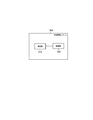
- FIG. 4 is a diagram illustrating the distributed power supply system 600 according to the embodiment.
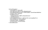
- FIG. 5 is a diagram illustrating an example of the first message according to the embodiment.
- FIG. 6 is a diagram illustrating an example of the first message according to the embodiment.
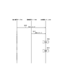
- FIG. 7 is a diagram illustrating the distributed power control method according to the embodiment.
- FIG. 8 is a diagram illustrating the distributed power control method according to the embodiment.
- the present disclosure has been made in order to solve the above-described problem, and enables appropriate control of a distributed power supply.
- the distributed power supply system has a distributed power supply.
- a communication unit that receives a first message from a power management server that controls the distributed power supply and receives a second message from a facility management server that monitors the distributed power supply; And a controller for controlling the distributed power supply based on the two messages.
- the control unit controls the distributed power supply based on the second message in preference to the first message when the first message and the second message conflict.
- drawings are schematic and ratios of dimensions may be different from actual ones. Therefore, specific dimensions and the like should be determined in consideration of the following description. Further, it is needless to say that the drawings may include portions having different dimensional relationships or ratios.
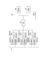
- the power system 100 includes a power management server 200, a facility 300, a facility management server 400, and a predetermined server 500.
- facilities 300A to 300C are illustrated as facilities 300.
- Each facility 300 is connected to the power system 110.
- the flow of power from the power system 110 to the facility 300 is referred to as a power flow
- the flow of power from the facility 300 to the power system 110 is referred to as a reverse flow.
- the power management server 200 is a server that controls a distributed power supply (for example, a distributed power supply 310 described later).
- the power management server 200 transmits a first message instructing the EMS 330 provided in the facility 300 to control the distributed power supply 310 provided in the facility 300.
- the power management server 200 may transmit a power flow control message (for example, DR; Demand @ Response) requesting power flow control, or may transmit a reverse power flow control message requesting reverse power flow control.
- the power management server 200 may transmit a power control message for controlling the operation state of the distributed power supply.
- the control level of the power flow or the reverse power flow may be represented by an absolute value (for example, WkW) or a relative value (for example, ⁇ %).
- the degree of control of the power flow or the reverse power flow may be represented by two or more levels.
- the power flow or reverse power flow control degree may be represented by a power rate (RTP; Real ⁇ Time ⁇ Pricing) determined by a current power supply and demand balance, or a power rate (TOU; Time ⁇ Of ⁇ Use) determined by a past power supply and demand balance. May be represented by
- the power management server 200 is managed by a power company such as a power generation company, a transmission and distribution company, and a retail company.
- the first message is a message for these power companies to adjust the power supply and demand balance of the power system 110.
- the facility 300 includes a distributed power source 310, a load device 320, and an EMS 330.
- the distributed power source 310 may be a fuel cell device that generates power using fuel.
- a fuel cell device is a device that generates power using fuel.
- the fuel cell device includes a solid oxide fuel cell (SOFC: Solid Oxide Fuel Cell), a polymer electrolyte fuel cell (PEFC: Polymer Electrolyte Fuel Cell), and a phosphoric acid fuel cell (PAFC: Phosphoric Acid Fuel Cell). And a molten carbonate fuel cell (MCFC: Molt Carbonate Fuel Cell).
- the distributed power source 310 may be a device that generates power using at least one natural energy among solar light, wind power, hydraulic power, geothermal power, and the like.
- the distributed power supply 310 may be a power storage device that performs power charging and power discharging.
- the load device 320 is a device that consumes power.
- the load device 320 is at least one of an air conditioner, a lighting device, an AV (Audio Visual) device, and the like.
- the EMS 330 is a device (EMS; Energy Management System) that manages the power of the facility 300.
- the EMS 330 corresponds to a control device.
- the EMS 330 may control the operation state of the distributed power supply 310 and the load device 320.
- the EMS 330 is an example of VEN (Virtual @ End @ Node).
- the equipment management server 400 is a server that monitors a distributed power supply (for example, the distributed power supply 310 described above).
- the facility management server 400 transmits, to the EMS 330 provided in the facility 300, a second message for performing maintenance of the distributed power supply 310 provided in the facility 300.
- the maintenance includes inspection for investigating the deterioration state of the equipment, maintenance for performing minor care at the time of inspection, repair for treating a malfunction of the equipment, and replacement for replacing existing equipment with new equipment. Note that the maintenance may be performed while the distributed power supply 310 is stopped, or may be performed while the distributed power supply 310 is operating.
- the facility management server 400 is managed by a facility supplier such as a manufacturer, a distributor, and a maintenance company of the distributed power supply 310.
- the predetermined server 500 is a server that relays the first message and the second message.
- the predetermined server 500 may transmit a first message for the facility 300 managed by the predetermined server 500 based on the first message for the facility 300 managed by the power management server 200.
- the predetermined server 500 may relay the second message transparently.
- the predetermined server 500 is managed by a resource aggregator.
- the resource aggregator is a power company that provides reverse power flow to a power generation company, a transmission / distribution company, a retail company, and the like in a VPP (Virtual Power Plant).
- the resource aggregator may be a power provider that generates surplus power (negawatt) by reducing power consumption of facilities managed by the resource aggregator. Such surplus power may be regarded as generated power.
- the resource aggregator may be a power provider that absorbs excessive power by increasing power consumption of a facility managed by the resource aggregator (for example, increasing the charge amount of the storage battery device).
- communication between the power management server 200 and the predetermined server 500, communication between the facility management server 400 and the predetermined server 500, and communication between the predetermined server 500 and the EMS 330 are performed according to the first protocol. May be.
- the communication between the EMS 330 and the distributed power source 310 and the communication between the EMS 330 and the load device 320 may be performed according to a second protocol different from the first protocol.
- a protocol conforming to Open @ ADR (Automated Demand @ Response) 2.0 or an original dedicated protocol can be used.
- a protocol conforming to ECHONET Lite, SEP (Smart Energy Profile) 2.0, KNX, or an original dedicated protocol can be used.
- the first protocol and the second protocol need only be different, and, for example, both may be proprietary dedicated protocols as long as they are protocols created according to different rules.
- the power management server 200 includes a database 210, a communication unit 220, and a control unit 230.
- the power management server 200 is an example of a VTN (Virtual Top Node).
- the database 210 is configured by a storage medium such as a non-volatile memory and / or an HDD (Hard Disk Drive), and stores data on the facility 300 managed by the power management server 200.
- the facility 300 managed by the power management server 200 may be a facility 300 having a contract with a power company.
- the data regarding the facility 300 may be demand power supplied from the power system 110 to the facility 300.
- the data on the facility 300 may be at least one of a type of the distributed power supply 310 provided in the facility 300, a specification of the distributed power supply 310 provided in the facility 300, and the like.
- the specification may be a rated generated power (W) and a maximum output power (W) of the distributed power supply 310.
- the communication unit 220 is configured by a communication module, and communicates with the EMS 330 via the predetermined server 500.
- the communication unit 220 performs communication according to the first protocol as described above.
- the control unit 230 is configured by a control circuit including a memory and a CPU (Central Processing Unit), and controls each component provided in the power management server 200. For example, the control unit 230 determines transmission of the first message from the viewpoint of the power supply and demand balance of the power system 110.
- the first message may be any of the following messages (a1) to (a7), or a message obtained by combining two or more of these messages.
- a message instructing an increase or decrease in the output of the distributed power supply 310 to maintain the power supply / demand balance (a2) A message instructing an operation stop or start of the distributed power supply 310 to maintain the power supply / demand balance (a3) ) Message indicating the time to start or stop operating the distributed power supply 310 to maintain the power supply and demand balance (a4) Message indicating the time or period during which the maintenance of the power supply and demand is required (a5) ) Message notifying completion of maintenance of power supply and demand balance (a6) Message instructing resumption of operation of distributed power supply 310 with maintenance completion of maintenance of power supply and demand (a7) Normal mode following maintenance completion of power supply and demand balance Prompting return to
- the first message may be at least one of a power flow control message, a reverse power flow control message, and a power control message.
- the facility management server 400 includes a database 410, a communication unit 420, and a control unit 430.
- the database 410 is configured by a storage medium such as a nonvolatile memory and / or an HDD, and manages information on a plurality of facilities 300.
- the database 410 may store basic information of facilities provided in each of the plurality of facilities 300.
- the database 410 stores, for example, a facility name, a facility ID, a facility name, a facility ID, an introduction year, an age, and a useful life in association with each other.
- the facility name is the name of the facility 300 where the facility is installed.
- the facility ID is an identifier for identifying the facility 300.
- the equipment name is the name of the equipment.
- the equipment ID is an identifier for identifying the equipment.
- the introduction year is the year when the equipment was introduced. Aging is the year that has elapsed since the equipment was introduced.
- the service life is determined by the manufacturer of the equipment or the like, and is information indicating a period in which the equipment can be used properly after the equipment is introduced.
- the database 410 may store, for each of the plurality of facilities 300, maintenance information of equipment provided in each of the plurality of facilities 300.
- the database 410 stores, for example, facility names, facility names, maintenance dates, maintenance outlines, and maintenance details in association with each other.
- the database 410 may store the facility ID and the facility ID in association with these pieces of information.
- the facility name and the facility name are as described above.
- the maintenance date is the date when the maintenance was performed.
- the maintenance summary is information indicating a summary of the maintenance, and the maintenance details are information indicating details of the maintenance.
- the maintenance information according to the embodiment may include at least a maintenance period (plan) for performing maintenance of the facility in the future.
- the maintenance information may include a maintenance period during which equipment maintenance was performed in the past.
- the communication unit 420 is constituted by a communication module, and communicates with the EMS 330 via the predetermined server 500.
- the communication unit 420 performs communication according to the first protocol as described above.
- the control unit 430 is configured by a control circuit including a memory, a CPU, and the like, and controls each component provided in the facility management server 400. For example, the control unit 430 determines transmission of the second message from the viewpoint of maintenance of the distributed power supply 310.
- the second message may be any of the following messages (b1) to (b6), or a message combining two or more of these messages.
- the distributed power system 600 includes a communication unit 610 and a control unit 620.
- the distributed power supply system 600 may be any system including the distributed power supply 310.
- the distributed power supply system 600 includes the distributed power supply 310 and the EMS 330.
- the distributed power supply system 600 may be configured by the distributed power supply 310 without including the EMS 330.
- the communication unit 610 is configured by a communication module, and communicates with the power management server 200 and the facility management server 400 via the predetermined server 500. That is, the communication unit 610 receives the first message from the power management server 200 and receives the second message from the facility management server 400.
- the control unit 620 is configured by a control circuit including a memory, a CPU, and the like, and controls each component provided in the distributed power supply system 600. For example, the control unit 620 controls the distributed power source 310 based on the first message and the second message.
- the control unit 620 controls the distributed power source 310 based on the second message in preference to the first message.
- the contention between the first message and the second message may be a case where the distributed power source 310 is controlled based on the second message for a time zone in which the distributed power source 310 is controlled based on the first message.
- a case may be considered in which the stop of the distributed power supply 310 is instructed based on the second message in a time zone in which the output increase or the output decrease of the distributed power supply 310 is instructed based on the first message.
- the distributed power supply 310 is controlled based on the first message for a time zone in which the distributed power supply 310 is controlled based on the second message.
- a case may be considered in which an increase or decrease in the output of the distributed power source 310 is instructed based on the first message in a time zone in which the stop of the distributed power source 310 is instructed based on the second message. That is, the contention between the first message and the second message means that the control executed based on the first message and the control executed based on the second message cannot be realized at the same time, or the control of both is realized at the same time. Includes situations in which doing so may cause inconvenience.
- the communication protocol of the first message is the same as the communication protocol of the second message.
- the control unit 620 transmits the first message and the second message.
- the second message may not be distinguished. Therefore, in the embodiment, the first message is configured to be identifiable as a message transmitted from the power management server 200, or the second message is a message transmitted from the facility management server 400. It is configured to be identifiable.
- the first message and the second message include an information element indicating the priority (here, ⁇ ns2: priority>).
- the control unit 620 determines which of the power management server 200 and the facility management server 400 the message received by the communication unit 610 has been transmitted based on the priority order. Specifically, as shown in FIG. 5, the priority of the first message is “100”, and as shown in FIG. 6, the priority of the second message is “1”.
- the predetermined value “1” may be defined as a priority that is used exclusively for the second message. That is, a priority other than the predetermined value “1” may be set based on the priority of the first message.
- the first message and the second message include an information element (here, ⁇ ns4: marketContext>) that can be used to identify the control of the distributed power source 310. May be.
- the control unit 620 determines which of the power management server 200 and the facility management server 400 the message received by the communication unit 610 has been transmitted from, based on the marketContext priority order. Specifically, as shown in FIG. 5, the marketContext of the first message is "DR", and as shown in FIG. 6, the marketContext of the second message is "Maintenance". It should be noted that in such a case, the predetermined value of "Maintenance" is a newly defined value.
- control unit 620 may refuse to accept the first message until the start of the distributed power supply 310 is performed. In such a case, when the reception of the first message is rejected, communication unit 610 may transmit a notification message indicating that control based on the first message is not performed to power management server 200. .
- distributed power supply control method a distributed power supply control method according to the embodiment will be described. 7 and 8, the predetermined server 500 is omitted.
- step S10 the power management server 200 transmits a first message to the distributed power system 600.
- step S11 the facility management server 400 sends a second message to the distributed power system 600.
- step S12 the distributed power system 600 determines whether the first message and the second message conflict.
- the distributed power supply system 600 may make the determination based on the priority order, or may make the determination based on the marketContext.
- the case where the first message and the second message conflict will be described.
- step S13 the distributed power supply system 600 controls the distributed power supply 310 based on the second message.
- the distributed power supply system 600 cancels the control based on the first message.
- distributed power supply system 600 may transmit a notification message indicating that control based on the first message is not performed to power management server 200. Such processing may be omitted when the control based on the first message is the same as the control based on the second message.
- the distributed power supply system 600 performs control based on the second message without performing control based on the first message. .
- step S20 the facility management server 400 transmits the second message to the distributed power system 600.
- step S21 the power management server 200 transmits a first message to the distributed power system 600.
- step S22 the distributed power system 600 refuses to accept the first message.
- the distributed power supply system 600 may refuse to accept the first message until the distributed power supply 310 is started.
- the activation of the distributed power supply 310 may be manually performed by a maintenance company, or may be performed in response to receiving a second message instructing the restart of the operation of the distributed power supply 310.
- step S23 the distributed power supply system 600 transmits to the power management server 200 a notification message indicating that control based on the first message is not performed.
- step S24 the distributed power supply system 600 controls the distributed power supply 310 based on the second message.
- the distributed power system 600 controls the distributed power supply 310 based on the second message with priority over the first message. According to such a configuration, the conflict between the first message and the second message can be appropriately resolved, and the distributed power source 310 can be appropriately controlled.
- the conflict between the first message and the second message is resolved based on a new finding that maintenance should be given priority over power supply and demand balance.
- the distributed power supply 310 is controlled based on the second message, it is possible to prevent such a premise from being broken when the maintenance company goes to the installation location of the distributed power supply 310. .
- the fuel cell device does not stop as scheduled. Can be avoided.
- the first message and the second message are transmitted to the EMS 330.
- the first message and the second message may be transmitted directly to the distributed power source 310.
- the EMS 330 may function as a router, and the EMS 330 may not be provided.
- the predetermined server 500 is provided. However, embodiments are not limited to this. The predetermined server 500 may not be provided. In such a case, the power management server 200 may relay the second message, and the facility management server 400 may relay the first message. Alternatively, the power management server 200 may directly transmit the first message to the distributed power supply system 600, and the facility management server 400 may directly transmit the second message to the distributed power supply system 600.
- the communication protocol of the first message is the same as the communication protocol of the second message has been described, but the embodiment is not limited to this.
- the communication protocol of the first message may be different from the communication protocol of the second message.
- the database 210 is provided in the power management server 200, but the embodiment is not limited to this.
- the database 210 may be provided in a server connected to the power management server 200 via a network.
- the database 410 is provided in the facility management server 400, but the embodiment is not limited to this.
- the database 410 may be provided in a server connected to the equipment management server 400 via a network.
- the first protocol is a protocol conforming to Open@ADR2.0 and the second protocol is a protocol conforming to ECHONET Lite has been exemplified.
- the first protocol is standardized as a protocol used in communication between the power management server 200 and the predetermined server 500, communication between the facility management server 400 and the predetermined server 500, and communication between the predetermined server 500 and the EMS 330. Any protocol may be used.
- the second protocol may be any protocol standardized as a protocol used in the facility 300.
- the distributed power system 600 gives priority to the first message over the first message.
- the distributed power source 310 is controlled based on the second message, the present invention is not limited to this.
- the second message includes a message instructing the restart of the operation of the distributed power supply 310 with the end of the maintenance of the distributed power supply 310, the first message and the second message may be regarded as not conflicting. .
- the distributed power supply system 600 stops the operation of the distributed power supply 310 for maintaining the power supply and demand balance rather than restarting the operation following the completion of the maintenance of the distributed power supply 310.
- the distributed power supply 310 may be controlled with priority. Further, in this case, the distributed power system 600 may transmit a notification message indicating that control based on the second message is not performed to the facility management server 400.
Abstract
A distributed power supply system including a distributed power supply is provided with: a communication unit which receives a first message from a power management server that controls the distributed power supply, and receives a second from a facility management server that monitors the distributed power supply; and a control unit which controls the distributed power supply on the basis of the first message and the second message. If the first message and the second message conflict, the control unit controls the distributed power supply on the basis of the second message in preference to the first message.
Description
本発明は、分散電源システム、制御装置、及び分散電源制御方法に関する。
The present invention relates to a distributed power supply system, a control device, and a distributed power supply control method.
近年、電力系統の電力需給バランスを維持するために、蓄電装置を分散電源として用いる技術(例えば、VPP(Virtual Power Plant)が知られている(例えば、特許文献1)。さらには、VPPなどで用いる分散電源として、燃料電池システムを用いることも考えられる。
2. Description of the Related Art In recent years, a technology (for example, VPP (Virtual Power Plant)) using a power storage device as a distributed power source to maintain a power supply / demand balance of a power system has been known (for example, Patent Document 1). It is also conceivable to use a fuel cell system as the distributed power source to be used.
第1の特徴に係る分散電源システムは、分散電源を有する。前記分散電源システムは、前記分散電源を制御する電力管理サーバから第1メッセージを受信し、前記分散電源を監視する設備管理サーバから第2メッセージを受信する通信部と、前記第1メッセージ及び前記第2メッセージに基づいて前記分散電源を制御する制御部とを備える。前記制御部は、前記第1メッセージ及び前記第2メッセージが競合した場合に、前記第1メッセージよりも優先して、前記第2メッセージに基づいて前記分散電源を制御する。
分散 The distributed power supply system according to the first feature has a distributed power supply. A communication unit that receives a first message from a power management server that controls the distributed power supply and receives a second message from a facility management server that monitors the distributed power supply; And a controller for controlling the distributed power supply based on the two messages. The control unit controls the distributed power supply based on the second message in preference to the first message when the first message and the second message conflict.
第2の特徴に係る制御装置は、分散電源を制御する電力管理サーバから第1メッセージを受信し、前記分散電源を監視する設備管理サーバから第2メッセージを受信する通信部と、前記第1メッセージ及び前記第2メッセージに基づいて前記分散電源を制御する制御部と、を備える。前記制御部は、前記第1メッセージ及び前記第2メッセージが競合した場合に、前記第1メッセージよりも優先して、前記第2メッセージに基づいて前記分散電源を制御する。
A control unit according to a second aspect, comprising: a communication unit that receives a first message from a power management server that controls a distributed power source, and receives a second message from a facility management server that monitors the distributed power source; And a control unit that controls the distributed power supply based on the second message. The control unit controls the distributed power supply based on the second message in preference to the first message when the first message and the second message conflict.
第3の特徴に係る分散電源制御方法は、分散電源を制御する電力管理サーバから第1メッセージを受信することと、前記分散電源を監視する設備管理サーバから第2メッセージを受信することと、前記第1メッセージ及び前記第2メッセージに基づいて前記分散電源を制御することとを含む。前記分散電源を制御することは、前記第1メッセージ及び前記第2メッセージが競合した場合に、前記第1メッセージよりも優先して、前記第2メッセージに基づいて前記分散電源を制御することを含む。
The distributed power source control method according to a third aspect, comprising: receiving a first message from a power management server that controls the distributed power source; receiving a second message from a facility management server that monitors the distributed power source; Controlling the distributed power source based on a first message and the second message. Controlling the distributed power source includes controlling the distributed power source based on the second message in preference to the first message when the first message and the second message conflict. .
電力系統の電力需給バランスを維持するために分散電源を制御する電力管理サーバ及び分散電源のメンテナンスを行うために分散電源を監視する設備管理サーバが互いに異なるエンティティに属するケースが想定される。
(4) It is assumed that the power management server that controls the distributed power supply to maintain the power supply and demand balance of the power system and the facility management server that monitors the distributed power supply to perform the maintenance of the distributed power supply belong to different entities.
発明者等は、鋭意検討の結果、このようなケースにおいて、設備管理サーバから送信されるメッセージ及び電力管理サーバから送信されるメッセージが競合すると、このようなメッセージの競合によって分散電源を適切に制御できない可能性があることを見出した。
As a result of intensive studies, the present inventors have found that in such a case, when a message transmitted from the equipment management server and a message transmitted from the power management server conflict, the distributed power source is appropriately controlled by such message conflict. I found that it might not be possible.
そこで、本開示は、上述した課題を解決するためになされたものであり、分散電源を適切に制御することを可能とする。
Therefore, the present disclosure has been made in order to solve the above-described problem, and enables appropriate control of a distributed power supply.
実施形態に係る分散電源システムは、分散電源を有する。前記分散電源システムは、前記分散電源を制御する電力管理サーバから第1メッセージを受信し、前記分散電源を監視する設備管理サーバから第2メッセージを受信する通信部と、前記第1メッセージ及び前記第2メッセージに基づいて前記分散電源を制御する制御部とを備える。前記制御部は、前記第1メッセージ及び前記第2メッセージが競合した場合に、前記第1メッセージよりも優先して、前記第2メッセージに基づいて前記分散電源を制御する。
The distributed power supply system according to the embodiment has a distributed power supply. A communication unit that receives a first message from a power management server that controls the distributed power supply and receives a second message from a facility management server that monitors the distributed power supply; And a controller for controlling the distributed power supply based on the two messages. The control unit controls the distributed power supply based on the second message in preference to the first message when the first message and the second message conflict.
以下において、実施形態について図面を参照しながら説明する。なお、以下の図面の記載において、同一又は類似の部分には、同一又は類似の符号を付している。
Hereinafter, embodiments will be described with reference to the drawings. In the following description of the drawings, the same or similar parts are denoted by the same or similar reference numerals.
但し、図面は模式的なものであり、各寸法の比率などは現実のものとは異なる場合があることに留意すべきである。従って、具体的な寸法などは以下の説明を参酌して判断すべきである。また、図面相互間においても互いの寸法の関係又は比率が異なる部分が含まれている場合があることは勿論である。
However, it should be noted that the drawings are schematic and ratios of dimensions may be different from actual ones. Therefore, specific dimensions and the like should be determined in consideration of the following description. Further, it is needless to say that the drawings may include portions having different dimensional relationships or ratios.
[実施形態]
(電力システム)
以下において、実施形態に係る電力システムについて説明する。 [Embodiment]
(Power system)
Hereinafter, a power system according to the embodiment will be described.
(電力システム)
以下において、実施形態に係る電力システムについて説明する。 [Embodiment]
(Power system)
Hereinafter, a power system according to the embodiment will be described.
図1に示すように、電力システム100は、電力管理サーバ200と、施設300と、設備管理サーバ400と、所定サーバ500とを有する。図1では、施設300として、施設300A~施設300Cが例示されている。
As shown in FIG. 1, the power system 100 includes a power management server 200, a facility 300, a facility management server 400, and a predetermined server 500. In FIG. 1, facilities 300A to 300C are illustrated as facilities 300.
各施設300は、電力系統110に接続される。以下において、電力系統110から施設300への電力の流れを潮流と称し、施設300から電力系統110への電力の流れを逆潮流と称する。
施 設 Each facility 300 is connected to the power system 110. Hereinafter, the flow of power from the power system 110 to the facility 300 is referred to as a power flow, and the flow of power from the facility 300 to the power system 110 is referred to as a reverse flow.
電力管理サーバ200は、分散電源(例えば、後述する分散電源310)を制御するサーバである。電力管理サーバ200は、施設300に設けられるEMS330に対して、施設300に設けられる分散電源310に対する制御を指示する第1メッセージを送信する。例えば、電力管理サーバ200は、潮流の制御を要求する潮流制御メッセージ(例えば、DR;Demand Response)を送信してもよく、逆潮流の制御を要求する逆潮流制御メッセージを送信してもよい。さらに、電力管理サーバ200は、分散電源の動作状態を制御する電源制御メッセージを送信してもよい。潮流又は逆潮流の制御度合いは、絶対値(例えば、○○kW)で表されてもよく、相対値(例えば、○○%)で表されてもよい。或いは、潮流又は逆潮流の制御度合いは、2以上のレベルで表されてもよい。潮流又は逆潮流の制御度合いは、現在の電力需給バランスによって定められる電力料金(RTP;Real Time Pricing)によって表されてもよく、過去の電力需給バランスによって定められる電力料金(TOU;Time Of Use)によって表されてもよい。
The power management server 200 is a server that controls a distributed power supply (for example, a distributed power supply 310 described later). The power management server 200 transmits a first message instructing the EMS 330 provided in the facility 300 to control the distributed power supply 310 provided in the facility 300. For example, the power management server 200 may transmit a power flow control message (for example, DR; Demand @ Response) requesting power flow control, or may transmit a reverse power flow control message requesting reverse power flow control. Further, the power management server 200 may transmit a power control message for controlling the operation state of the distributed power supply. The control level of the power flow or the reverse power flow may be represented by an absolute value (for example, WkW) or a relative value (for example, ○%). Alternatively, the degree of control of the power flow or the reverse power flow may be represented by two or more levels. The power flow or reverse power flow control degree may be represented by a power rate (RTP; Real \ Time \ Pricing) determined by a current power supply and demand balance, or a power rate (TOU; Time \ Of \ Use) determined by a past power supply and demand balance. May be represented by
例えば、電力管理サーバ200は、発電事業者、送配電事業者、小売事業者などの電力事業者によって管理される。第1メッセージは、これらの電力事業者が電力系統110の電力需給バランスを調整するためのメッセージである。
For example, the power management server 200 is managed by a power company such as a power generation company, a transmission and distribution company, and a retail company. The first message is a message for these power companies to adjust the power supply and demand balance of the power system 110.
施設300は、分散電源310、負荷機器320及びEMS330を有する。
The facility 300 includes a distributed power source 310, a load device 320, and an EMS 330.
分散電源310は、燃料を用いて発電を行う燃料電池装置であってもよい。燃料電池装置は、燃料を用いて発電を行う装置である。例えば、燃料電池装置は、固体酸化物型燃料電池(SOFC:Solid Oxide Fuel Cell)、固体高分子型燃料電池(PEFC:Polymer Electrolyte Fuel Cell)、リン酸型燃料電池(PAFC:Phosphoric Acid Fuel Cell)、及び溶融炭酸塩型燃料電池(MCFC:Molten Carbonate Fuel Cell)のうち少なくとも1つであってもよい。分散電源310は、太陽光、風力、水力、及び地熱などのうち少なくとも1つの自然エネルギーを用いて発電を行う装置であってもよい。分散電源310は、電力の充電及び電力の放電を行う蓄電装置であってもよい。
The distributed power source 310 may be a fuel cell device that generates power using fuel. A fuel cell device is a device that generates power using fuel. For example, the fuel cell device includes a solid oxide fuel cell (SOFC: Solid Oxide Fuel Cell), a polymer electrolyte fuel cell (PEFC: Polymer Electrolyte Fuel Cell), and a phosphoric acid fuel cell (PAFC: Phosphoric Acid Fuel Cell). And a molten carbonate fuel cell (MCFC: Molt Carbonate Fuel Cell). The distributed power source 310 may be a device that generates power using at least one natural energy among solar light, wind power, hydraulic power, geothermal power, and the like. The distributed power supply 310 may be a power storage device that performs power charging and power discharging.
負荷機器320は、電力を消費する機器である。例えば、負荷機器320は、空調機器、照明機器、及びAV(Audio Visual)機器などのうち少なくとも1つである。
The load device 320 is a device that consumes power. For example, the load device 320 is at least one of an air conditioner, a lighting device, an AV (Audio Visual) device, and the like.
EMS330は、施設300の電力を管理する装置(EMS;Energy Management System)である。EMS330は、制御装置に相当する。EMS330は、分散電源310及び負荷機器320の動作状態を制御してもよい。EMS330は、VEN(Virtual End Node)の一例である。
The EMS 330 is a device (EMS; Energy Management System) that manages the power of the facility 300. The EMS 330 corresponds to a control device. The EMS 330 may control the operation state of the distributed power supply 310 and the load device 320. The EMS 330 is an example of VEN (Virtual @ End @ Node).
設備管理サーバ400は、分散電源(例えば、上述した分散電源310)を監視するサーバである。設備管理サーバ400は、施設300に設けられるEMS330に対して、施設300に設けられる分散電源310のメンテナンスを行うための第2メッセージを送信する。例えば、メンテナンスは、設備の劣化状態を調査する点検、点検時に軽微な手入れを行う保守、設備の不具合を処置する修繕、及び既存の設備を新しい設備に交換する取替等を含む。なお、メンテナンスは、分散電源310が停止している間に行われてもよいし、分散電源310が運転している間に行われてもよい。
The equipment management server 400 is a server that monitors a distributed power supply (for example, the distributed power supply 310 described above). The facility management server 400 transmits, to the EMS 330 provided in the facility 300, a second message for performing maintenance of the distributed power supply 310 provided in the facility 300. For example, the maintenance includes inspection for investigating the deterioration state of the equipment, maintenance for performing minor care at the time of inspection, repair for treating a malfunction of the equipment, and replacement for replacing existing equipment with new equipment. Note that the maintenance may be performed while the distributed power supply 310 is stopped, or may be performed while the distributed power supply 310 is operating.
例えば、設備管理サーバ400は、分散電源310の製造業者、販売業者、及びメンテナンス業者などの設備業者によって管理される。
For example, the facility management server 400 is managed by a facility supplier such as a manufacturer, a distributor, and a maintenance company of the distributed power supply 310.
所定サーバ500は、第1メッセージ及び第2メッセージを中継するサーバである。所定サーバ500は、電力管理サーバ200によって管理される施設300を対象とする第1メッセージに基づいて、所定サーバ500によって管理される施設300を対象とする第1メッセージを送信してもよい。所定サーバ500は、第2メッセージを透過的に中継してもよい。
The predetermined server 500 is a server that relays the first message and the second message. The predetermined server 500 may transmit a first message for the facility 300 managed by the predetermined server 500 based on the first message for the facility 300 managed by the power management server 200. The predetermined server 500 may relay the second message transparently.
例えば、所定サーバ500は、リソースアグリゲータによって管理される。リソースアグリゲータは、VPP(Virtual Power Plant)において、発電事業者、送配電事業者及び小売事業者などに逆潮流の電力を提供する電力事業者である。リソースアグリゲータは、リソースアグリゲータによって管理される施設の消費電力の削減によって余剰電力(ネガワット)を生み出す電力事業者であってもよい。このような余剰電力は発電電力と見做されてもよい。リソースアグリゲータは、リソースアグリゲータによって管理される施設の消費電力の増大(例えば、蓄電池装置の充電量の増大)によって過剰な電力を吸収する電力事業者であってもよい。
{For example, the predetermined server 500 is managed by a resource aggregator. The resource aggregator is a power company that provides reverse power flow to a power generation company, a transmission / distribution company, a retail company, and the like in a VPP (Virtual Power Plant). The resource aggregator may be a power provider that generates surplus power (negawatt) by reducing power consumption of facilities managed by the resource aggregator. Such surplus power may be regarded as generated power. The resource aggregator may be a power provider that absorbs excessive power by increasing power consumption of a facility managed by the resource aggregator (for example, increasing the charge amount of the storage battery device).
実施形態において、電力管理サーバ200と所定サーバ500との間の通信、設備管理サーバ400と所定サーバ500との間の通信、及び所定サーバ500とEMS330との間の通信は、第1プロトコルに従って行われてもよい。一方で、EMS330と分散電源310との間の通信及びEMS330と負荷機器320との間の通信は、第1プロトコルとは異なる第2プロトコルに従って行われてもよい。例えば、第1プロトコルとしては、Open ADR(Automated Demand Response)2.0に準拠するプロトコル、或いは、独自の専用プロトコルを用いることができる。例えば、第2プロトコルは、ECHONET Liteに準拠するプロトコル、SEP(Smart Energy Profile)2.0、KNX、或いは、独自の専用プロトコルを用いることができる。なお、第1プロトコルと第2プロトコルは異なっていればよく、例えば、両方が独自の専用プロトコルであっても異なる規則で作られたプロトコルであればよい。
In the embodiment, communication between the power management server 200 and the predetermined server 500, communication between the facility management server 400 and the predetermined server 500, and communication between the predetermined server 500 and the EMS 330 are performed according to the first protocol. May be. On the other hand, the communication between the EMS 330 and the distributed power source 310 and the communication between the EMS 330 and the load device 320 may be performed according to a second protocol different from the first protocol. For example, as the first protocol, a protocol conforming to Open @ ADR (Automated Demand @ Response) 2.0 or an original dedicated protocol can be used. For example, as the second protocol, a protocol conforming to ECHONET Lite, SEP (Smart Energy Profile) 2.0, KNX, or an original dedicated protocol can be used. It should be noted that the first protocol and the second protocol need only be different, and, for example, both may be proprietary dedicated protocols as long as they are protocols created according to different rules.
(電力管理サーバ)
以下において、実施形態に係る電力管理サーバについて説明する。図2に示すように、電力管理サーバ200は、データベース210と、通信部220と、制御部230とを有する。電力管理サーバ200は、VTN(Virtual Top Node)の一例である。 (Power management server)
Hereinafter, the power management server according to the embodiment will be described. As shown in FIG. 2, thepower management server 200 includes a database 210, a communication unit 220, and a control unit 230. The power management server 200 is an example of a VTN (Virtual Top Node).
以下において、実施形態に係る電力管理サーバについて説明する。図2に示すように、電力管理サーバ200は、データベース210と、通信部220と、制御部230とを有する。電力管理サーバ200は、VTN(Virtual Top Node)の一例である。 (Power management server)
Hereinafter, the power management server according to the embodiment will be described. As shown in FIG. 2, the
データベース210は、不揮発性メモリ又は/及びHDD(Hard Disk Drive)などの記憶媒体によって構成されており、電力管理サーバ200によって管理される施設300に関するデータを記憶する。電力管理サーバ200によって管理される施設300は、電力事業者と契約を有する施設300であってもよい。例えば、施設300に関するデータは、電力系統110から施設300に供給される需要電力であってもよい。施設300に関するデータは、施設300に設けられる分散電源310の種別、及び施設300に設けられる分散電源310のスペックなどのうち少なくとも1つであってもよい。スペックは、分散電源310の定格発電電力(W)及び最大出力電力(W)などであってもよい。
The database 210 is configured by a storage medium such as a non-volatile memory and / or an HDD (Hard Disk Drive), and stores data on the facility 300 managed by the power management server 200. The facility 300 managed by the power management server 200 may be a facility 300 having a contract with a power company. For example, the data regarding the facility 300 may be demand power supplied from the power system 110 to the facility 300. The data on the facility 300 may be at least one of a type of the distributed power supply 310 provided in the facility 300, a specification of the distributed power supply 310 provided in the facility 300, and the like. The specification may be a rated generated power (W) and a maximum output power (W) of the distributed power supply 310.
通信部220は、通信モジュールによって構成されており、所定サーバ500を介してEMS330と通信を行う。通信部220は、上述したように、第1プロトコルに従って通信を行う。
The communication unit 220 is configured by a communication module, and communicates with the EMS 330 via the predetermined server 500. The communication unit 220 performs communication according to the first protocol as described above.
制御部230は、メモリ及びCPU(Central Processing Unit)などを含む制御回路によって構成されており、電力管理サーバ200に設けられる各構成を制御する。例えば、制御部230は、電力系統110の電力需給バランスの観点から第1メッセージの送信を決定する。第1メッセージは、下記の(a1)乃至(a7)のメッセージのいずれか、又はこれらのメッセージのうち2以上のメッセージを組み合わせたメッセージであってもよい。
The control unit 230 is configured by a control circuit including a memory and a CPU (Central Processing Unit), and controls each component provided in the power management server 200. For example, the control unit 230 determines transmission of the first message from the viewpoint of the power supply and demand balance of the power system 110. The first message may be any of the following messages (a1) to (a7), or a message obtained by combining two or more of these messages.
(a1)電力需給バランスを維持するために分散電源310の出力増大又は出力減少を指示するメッセージ
(a2)電力需給バランスを維持するために分散電源310の運転停止又は運転開始を指示するメッセージ
(a3)電力需給バランスを維持するために分散電源310の運転停止を開始する時刻又は運転を開始する時刻を指示するメッセージ
(a4)電力需給バランスの維持を必要とする時間又は期間を指示するメッセージ
(a5)電力需給バランスの維持の終了を通知するメッセージ
(a6)電力需給バランスの維持の終了に伴って分散電源310の運転再開を指示するメッセージ
(a7)電力需給バランスの維持の終了に伴って通常モードへの復帰を促すメッセージ (A1) A message instructing an increase or decrease in the output of the distributedpower supply 310 to maintain the power supply / demand balance (a2) A message instructing an operation stop or start of the distributed power supply 310 to maintain the power supply / demand balance (a3) ) Message indicating the time to start or stop operating the distributed power supply 310 to maintain the power supply and demand balance (a4) Message indicating the time or period during which the maintenance of the power supply and demand is required (a5) ) Message notifying completion of maintenance of power supply and demand balance (a6) Message instructing resumption of operation of distributed power supply 310 with maintenance completion of maintenance of power supply and demand (a7) Normal mode following maintenance completion of power supply and demand balance Prompting return to
(a2)電力需給バランスを維持するために分散電源310の運転停止又は運転開始を指示するメッセージ
(a3)電力需給バランスを維持するために分散電源310の運転停止を開始する時刻又は運転を開始する時刻を指示するメッセージ
(a4)電力需給バランスの維持を必要とする時間又は期間を指示するメッセージ
(a5)電力需給バランスの維持の終了を通知するメッセージ
(a6)電力需給バランスの維持の終了に伴って分散電源310の運転再開を指示するメッセージ
(a7)電力需給バランスの維持の終了に伴って通常モードへの復帰を促すメッセージ (A1) A message instructing an increase or decrease in the output of the distributed
上述したように、第1メッセージは、潮流制御メッセージ、逆潮流制御メッセージ、及び電源制御メッセージのうち少なくとも1つであってもよい。
As described above, the first message may be at least one of a power flow control message, a reverse power flow control message, and a power control message.
(設備管理サーバ)
以下において、実施形態に係る設備管理サーバについて説明する。図3に示すように、設備管理サーバ400は、データベース410と、通信部420と、制御部430とを有する。 (Facility management server)
Hereinafter, the facility management server according to the embodiment will be described. As shown in FIG. 3, thefacility management server 400 includes a database 410, a communication unit 420, and a control unit 430.
以下において、実施形態に係る設備管理サーバについて説明する。図3に示すように、設備管理サーバ400は、データベース410と、通信部420と、制御部430とを有する。 (Facility management server)
Hereinafter, the facility management server according to the embodiment will be described. As shown in FIG. 3, the
データベース410は、不揮発性メモリ又は/及びHDDなどの記憶媒体によって構成されており、複数の施設300に関する情報を管理する。
The database 410 is configured by a storage medium such as a nonvolatile memory and / or an HDD, and manages information on a plurality of facilities 300.
データベース410は、複数の施設300のそれぞれに設けられる設備の基本情報を記憶してもよい。データベース410は、例えば、施設名、施設ID、設備名、設備ID、導入年、経年及び耐用年数を対応付けて記憶する。施設名は、設備が設置される施設300の名称である。施設IDは、施設300を識別する識別子である。設備名は、設備の名称である。設備IDは、設備を識別する識別子である。導入年は、設備が導入された年である。経年は、設備が導入されてから経過した年である。耐用年数は、設備のメーカ等によって定められており、設備を導入してから設備を適切に使用可能な期間を示す情報である。
The database 410 may store basic information of facilities provided in each of the plurality of facilities 300. The database 410 stores, for example, a facility name, a facility ID, a facility name, a facility ID, an introduction year, an age, and a useful life in association with each other. The facility name is the name of the facility 300 where the facility is installed. The facility ID is an identifier for identifying the facility 300. The equipment name is the name of the equipment. The equipment ID is an identifier for identifying the equipment. The introduction year is the year when the equipment was introduced. Aging is the year that has elapsed since the equipment was introduced. The service life is determined by the manufacturer of the equipment or the like, and is information indicating a period in which the equipment can be used properly after the equipment is introduced.
データベース410は、複数の施設300のそれぞれについて、複数の施設300のそれぞれに設けられる設備のメンテナンス情報を記憶してもよい。データベース410は、例えば、施設名、設備名、メンテナンス日、メンテナンス概要及びメンテナンス詳細を対応付けて記憶する。データベース410は、これらの情報とともに、施設ID及び設備IDを対応付けて記憶してもよい。施設名及び設備名は、上述した通りである。メンテナンス日は、メンテナンスが行われた日付である。メンテナンス概要は、メンテナンスの概要を示す情報であり、メンテナンス詳細は、メンテナンスの詳細を示す情報である。実施形態に係るメンテナンス情報は、少なくとも、将来において設備のメンテナンスを行うメンテナンス期間(予定)を含んでいればよい。メンテナンス情報は、過去において設備のメンテナンスを行ったメンテナンス期間を含んでいてもよい。
The database 410 may store, for each of the plurality of facilities 300, maintenance information of equipment provided in each of the plurality of facilities 300. The database 410 stores, for example, facility names, facility names, maintenance dates, maintenance outlines, and maintenance details in association with each other. The database 410 may store the facility ID and the facility ID in association with these pieces of information. The facility name and the facility name are as described above. The maintenance date is the date when the maintenance was performed. The maintenance summary is information indicating a summary of the maintenance, and the maintenance details are information indicating details of the maintenance. The maintenance information according to the embodiment may include at least a maintenance period (plan) for performing maintenance of the facility in the future. The maintenance information may include a maintenance period during which equipment maintenance was performed in the past.
通信部420は、通信モジュールによって構成されており、所定サーバ500を介してEMS330と通信を行う。通信部420は、上述したように、第1プロトコルに従って通信を行う。
The communication unit 420 is constituted by a communication module, and communicates with the EMS 330 via the predetermined server 500. The communication unit 420 performs communication according to the first protocol as described above.
制御部430は、メモリ及びCPUなどを含む制御回路によって構成されており、設備管理サーバ400に設けられる各構成を制御する。例えば、制御部430は、分散電源310のメンテナンスの観点から第2メッセージの送信を決定する。第2メッセージは、下記の(b1)乃至(b6)のメッセージのいずれか、又はこれらのメッセージのうち2以上のメッセージを組み合わせたメッセージであってもよい。
The control unit 430 is configured by a control circuit including a memory, a CPU, and the like, and controls each component provided in the facility management server 400. For example, the control unit 430 determines transmission of the second message from the viewpoint of maintenance of the distributed power supply 310. The second message may be any of the following messages (b1) to (b6), or a message combining two or more of these messages.
(b1)メンテナンスを開始するために分散電源310の運転停止を指示するメッセージ
(b2)メンテナンスを開始するために分散電源310の運転停止を開始する時刻を指示するメッセージ
(b3)分散電源310のメンテナンスに要する時間又は期間を指示するメッセージ
(b4)分散電源310のメンテナンスの終了を通知するメッセージ
(b5)分散電源310のメンテナンスの終了に伴って分散電源310の運転再開を指示するメッセージ
(b6)分散電源310のメンテナンスの終了に伴って通常モードへの復帰を促すメッセージ (B1) Message instructing stop of operation of distributedpower source 310 to start maintenance (b2) Message instructing time to start operation of distributed power source 310 to start maintenance (b3) Maintenance of distributed power source 310 (B4) A message notifying the end of the maintenance of the distributed power source 310 (b5) A message instructing a restart of the operation of the distributed power source 310 with the end of the maintenance of the distributed power source 310 (b6) Distributed Message prompting return to normal mode with the end of power supply 310 maintenance
(b2)メンテナンスを開始するために分散電源310の運転停止を開始する時刻を指示するメッセージ
(b3)分散電源310のメンテナンスに要する時間又は期間を指示するメッセージ
(b4)分散電源310のメンテナンスの終了を通知するメッセージ
(b5)分散電源310のメンテナンスの終了に伴って分散電源310の運転再開を指示するメッセージ
(b6)分散電源310のメンテナンスの終了に伴って通常モードへの復帰を促すメッセージ (B1) Message instructing stop of operation of distributed
(分散電源システム)
以下において、実施形態に係る分散電源システムについて説明する。図4に示すように、分散電源システム600は、通信部610と、制御部620とを有する。分散電源システム600は、分散電源310を含むシステムであればよい。例えば、分散電源システム600は、分散電源310及びEMS330によって構成される。分散電源システム600は、EMS330を含まずに分散電源310によって構成されてもよい。 (Distributed power system)
Hereinafter, a distributed power system according to the embodiment will be described. As shown in FIG. 4, the distributedpower system 600 includes a communication unit 610 and a control unit 620. The distributed power supply system 600 may be any system including the distributed power supply 310. For example, the distributed power supply system 600 includes the distributed power supply 310 and the EMS 330. The distributed power supply system 600 may be configured by the distributed power supply 310 without including the EMS 330.
以下において、実施形態に係る分散電源システムについて説明する。図4に示すように、分散電源システム600は、通信部610と、制御部620とを有する。分散電源システム600は、分散電源310を含むシステムであればよい。例えば、分散電源システム600は、分散電源310及びEMS330によって構成される。分散電源システム600は、EMS330を含まずに分散電源310によって構成されてもよい。 (Distributed power system)
Hereinafter, a distributed power system according to the embodiment will be described. As shown in FIG. 4, the distributed
通信部610は、通信モジュールによって構成されており、所定サーバ500を介して電力管理サーバ200及び設備管理サーバ400と通信を行う。すなわち、通信部610は、電力管理サーバ200から第1メッセージを受信し、設備管理サーバ400から第2メッセージを受信する。
The communication unit 610 is configured by a communication module, and communicates with the power management server 200 and the facility management server 400 via the predetermined server 500. That is, the communication unit 610 receives the first message from the power management server 200 and receives the second message from the facility management server 400.
制御部620は、メモリ及びCPUなどを含む制御回路によって構成されており、分散電源システム600に設けられる各構成を制御する。例えば、制御部620は、第1メッセージ及び第2メッセージに基づいて分散電源310を制御する。
The control unit 620 is configured by a control circuit including a memory, a CPU, and the like, and controls each component provided in the distributed power supply system 600. For example, the control unit 620 controls the distributed power source 310 based on the first message and the second message.
実施形態において、制御部620は、第1メッセージ及び第2メッセージが競合した場合に、第1メッセージよりも優先して、第2メッセージに基づいて分散電源310を制御する。第1メッセージ及び第2メッセージの競合とは、第1メッセージに基づいて分散電源310が制御されている時間帯を対象として、第2メッセージに基づいて分散電源310を制御するケースが考えられる。例えば、第1メッセージに基づいて分散電源310の出力増大又は出力減少が指示されている時間帯において、第2メッセージに基づいて分散電源310の停止が指示されるケースが考えられる。或いは、第2メッセージに基づいて分散電源310が制御されている時間帯を対象として、第1メッセージに基づいて分散電源310を制御するケースが考えられる。例えば、第2メッセージに基づいて分散電源310の停止が指示されている時間帯において、第1メッセージに基づいて分散電源310の出力増大又は出力減少が指示されるケースが考えられる。つまり、第1メッセージ及び第2メッセージの競合とは、第1メッセージに基づいて実行される制御と第2メッセージに基づいて実行される制御とが同時に実現し得ない、または両者の制御を同時に実現することで不具合が生じ得る状況を含む。
In the embodiment, when the first message and the second message compete with each other, the control unit 620 controls the distributed power source 310 based on the second message in preference to the first message. The contention between the first message and the second message may be a case where the distributed power source 310 is controlled based on the second message for a time zone in which the distributed power source 310 is controlled based on the first message. For example, a case may be considered in which the stop of the distributed power supply 310 is instructed based on the second message in a time zone in which the output increase or the output decrease of the distributed power supply 310 is instructed based on the first message. Alternatively, there may be a case where the distributed power supply 310 is controlled based on the first message for a time zone in which the distributed power supply 310 is controlled based on the second message. For example, a case may be considered in which an increase or decrease in the output of the distributed power source 310 is instructed based on the first message in a time zone in which the stop of the distributed power source 310 is instructed based on the second message. That is, the contention between the first message and the second message means that the control executed based on the first message and the control executed based on the second message cannot be realized at the same time, or the control of both is realized at the same time. Includes situations in which doing so may cause inconvenience.
ここで、第1メッセージの通信プロトコルが第2メッセージの通信プロトコルと同じであるケースについて考える。実施形態では、所定サーバ500から分散電源システム600に第1メッセージ及び第2メッセージが送信されるため、第1メッセージ及び第2メッセージの通信プロトコルが同じである場合に、制御部620が第1メッセージ及び第2メッセージを区別できない可能性が考えられる。従って、実施形態においては、第1メッセージは、電力管理サーバ200から送信されるメッセージであることを識別可能に構成されており、或いは、第2メッセージは、設備管理サーバ400から送信されるメッセージであることを識別可能に構成されている。
Here, consider a case where the communication protocol of the first message is the same as the communication protocol of the second message. In the embodiment, since the first message and the second message are transmitted from the predetermined server 500 to the distributed power system 600, when the communication protocol of the first message and the second message is the same, the control unit 620 transmits the first message and the second message. And the second message may not be distinguished. Therefore, in the embodiment, the first message is configured to be identifiable as a message transmitted from the power management server 200, or the second message is a message transmitted from the facility management server 400. It is configured to be identifiable.
例えば、第1メッセージ及び第2メッセージの通信プロトコルがOpen ADR2.0に準拠するケースについて考える。
{For example, consider a case where the communication protocol of the first message and the second message conforms to Open@ADR2.0.
第1に、図5及び図6に示すように、第1メッセージ及び第2メッセージは、優先順位を示す情報要素(ここでは、<ns2:priority>)を含む。制御部620は、通信部610によって受信されるメッセージが電力管理サーバ200及び設備管理サーバ400のいずれから送信されたのかを優先順に基づいて判定する。具体的には、図5に示すように、第1メッセージの優先順位は“100”であり、図6に示すように、第2メッセージの優先順位は“1”である。このようなケースにおいて、“1”という所定値は、第2メッセージに専用で用いられる優先順位として定められていてもよい。すなわち、“1”という所定値以外の優先順位については、第1メッセージの優先順位に基づいて設定されてもよい。
First, as shown in FIGS. 5 and 6, the first message and the second message include an information element indicating the priority (here, <ns2: priority>). The control unit 620 determines which of the power management server 200 and the facility management server 400 the message received by the communication unit 610 has been transmitted based on the priority order. Specifically, as shown in FIG. 5, the priority of the first message is “100”, and as shown in FIG. 6, the priority of the second message is “1”. In such a case, the predetermined value “1” may be defined as a priority that is used exclusively for the second message. That is, a priority other than the predetermined value “1” may be set based on the priority of the first message.
第2に、図5及び図6に示すように、第1メッセージ及び第2メッセージは、分散電源310に対する制御の識別に用いることが可能な情報要素(ここでは、<ns4:marketContext>)を含んでもよい。制御部620は、通信部610によって受信されるメッセージが電力管理サーバ200及び設備管理サーバ400のいずれから送信されたのかをmarketContext優先順に基づいて判定する。具体的には、図5に示すように、第1メッセージのmarketContextは“DR”であり、図6に示すように、第2メッセージのmarketContextは“Maintenance”である。このようなケースにおいて、“Maintenance”という所定値は、新たに定義される値であることに留意すべきである。
Second, as shown in FIGS. 5 and 6, the first message and the second message include an information element (here, <ns4: marketContext>) that can be used to identify the control of the distributed power source 310. May be. The control unit 620 determines which of the power management server 200 and the facility management server 400 the message received by the communication unit 610 has been transmitted from, based on the marketContext priority order. Specifically, as shown in FIG. 5, the marketContext of the first message is "DR", and as shown in FIG. 6, the marketContext of the second message is "Maintenance". It should be noted that in such a case, the predetermined value of "Maintenance" is a newly defined value.
さらに、制御部620は、分散電源310の停止を指示する第2メッセージを受信した後において、分散電源310の起動が行われるまで第1メッセージの受け付けを拒否してもよい。このようなケースにおいて、通信部610は、第1メッセージの受け付けが拒否された場合に、第1メッセージに基づいた制御が行われない旨を示す通知メッセージを電力管理サーバ200に送信してもよい。
Further, after receiving the second message instructing the stop of the distributed power supply 310, the control unit 620 may refuse to accept the first message until the start of the distributed power supply 310 is performed. In such a case, when the reception of the first message is rejected, communication unit 610 may transmit a notification message indicating that control based on the first message is not performed to power management server 200. .
(分散電源制御方法)
以下において、実施形態に係る分散電源制御方法について説明する。図7及び図8では、所定サーバ500が省略されている。 (Distributed power supply control method)
Hereinafter, a distributed power supply control method according to the embodiment will be described. 7 and 8, thepredetermined server 500 is omitted.
以下において、実施形態に係る分散電源制御方法について説明する。図7及び図8では、所定サーバ500が省略されている。 (Distributed power supply control method)
Hereinafter, a distributed power supply control method according to the embodiment will be described. 7 and 8, the
第1に、第1メッセージに基づいて分散電源310が制御されている時間帯を対象として、第2メッセージに基づいて分散電源310を制御するケースについて考える。
First, consider a case where the distributed power supply 310 is controlled based on the second message for a time zone in which the distributed power supply 310 is controlled based on the first message.
ステップS10において、電力管理サーバ200は、第1メッセージを分散電源システム600に送信する。
In step S10, the power management server 200 transmits a first message to the distributed power system 600.
ステップS11において、設備管理サーバ400は、第2メッセージを分散電源システム600に送信する。
In step S11, the facility management server 400 sends a second message to the distributed power system 600.
ステップS12において、分散電源システム600は、第1メッセージ及び第2メッセージが競合するか否かを判定する。分散電源システム600は、優先順位に基づいて判定を行ってもよく、marketContextに基づいて判定を行ってもよい。ここでは、第1メッセージ及び第2メッセージが競合するケースについて説明を続ける。
In step S12, the distributed power system 600 determines whether the first message and the second message conflict. The distributed power supply system 600 may make the determination based on the priority order, or may make the determination based on the marketContext. Here, the case where the first message and the second message conflict will be described.
ステップS13において、分散電源システム600は、第2メッセージに基づいて、分散電源310を制御する。分散電源システム600は、第1メッセージに基づいて分散電源310の制御を開始していた場合には、第1メッセージに基づいた制御を取り消す。また、分散電源システム600は、第1メッセージに基づいた制御が行われない旨を示す通知メッセージを電力管理サーバ200に送信してもよい。このような処理は、第1メッセージに基づいた制御が第2メッセージに基づいた制御と同じである場合に省略されてもよい。一方で、分散電源システム600は、第1メッセージに基づいて分散電源310の制御を開始していない場合には、第1メッセージに基づいた制御を行わずに、第2メッセージに基づいた制御を行う。
In step S13, the distributed power supply system 600 controls the distributed power supply 310 based on the second message. When the control of the distributed power supply 310 has been started based on the first message, the distributed power supply system 600 cancels the control based on the first message. Further, distributed power supply system 600 may transmit a notification message indicating that control based on the first message is not performed to power management server 200. Such processing may be omitted when the control based on the first message is the same as the control based on the second message. On the other hand, when the control of the distributed power supply 310 has not been started based on the first message, the distributed power supply system 600 performs control based on the second message without performing control based on the first message. .
第2に、第2メッセージに基づいて分散電源310が制御されている時間帯を対象として、第1メッセージに基づいて分散電源310を制御するケースについて考える。
{Secondly, a case will be considered in which the distributed power source 310 is controlled based on the first message for a time zone in which the distributed power source 310 is controlled based on the second message.
ステップS20において、設備管理サーバ400は、第2メッセージを分散電源システム600に送信する。
In step S20, the facility management server 400 transmits the second message to the distributed power system 600.
ステップS21において、電力管理サーバ200は、第1メッセージを分散電源システム600に送信する。
In step S21, the power management server 200 transmits a first message to the distributed power system 600.
ステップS22において、分散電源システム600は、第1メッセージの受け付けを拒否する。例えば、分散電源システム600は、第2メッセージが分散電源310の停止を指示するメッセージである場合に、分散電源310の起動が行われるまで第1メッセージの受け付けを拒否してもよい。ここで、分散電源310の起動は、メンテナンス業者によって手動で行われてもよく、分散電源310の運転再開を指示する第2メッセージの受信に応じて行われてもよい。
(4) In step S22, the distributed power system 600 refuses to accept the first message. For example, when the second message is a message instructing the stop of the distributed power supply 310, the distributed power supply system 600 may refuse to accept the first message until the distributed power supply 310 is started. Here, the activation of the distributed power supply 310 may be manually performed by a maintenance company, or may be performed in response to receiving a second message instructing the restart of the operation of the distributed power supply 310.
ステップS23において、分散電源システム600は、第1メッセージに基づいた制御が行われない旨を示す通知メッセージを電力管理サーバ200に送信する。
In step S23, the distributed power supply system 600 transmits to the power management server 200 a notification message indicating that control based on the first message is not performed.
ステップS24において、分散電源システム600は、第2メッセージに基づいて、分散電源310を制御する。
In step S24, the distributed power supply system 600 controls the distributed power supply 310 based on the second message.
(作用及び効果)
実施形態では、分散電源システム600は、第1メッセージ及び第2メッセージが競合した場合に、第1メッセージよりも優先して、第2メッセージに基づいて分散電源310を制御する。このような構成によれば、第1メッセージ及び第2メッセージの競合を適切に解決することができ、分散電源310を適切に制御することができる。 (Action and effect)
In the embodiment, when the first message and the second message compete with each other, the distributedpower system 600 controls the distributed power supply 310 based on the second message with priority over the first message. According to such a configuration, the conflict between the first message and the second message can be appropriately resolved, and the distributed power source 310 can be appropriately controlled.
実施形態では、分散電源システム600は、第1メッセージ及び第2メッセージが競合した場合に、第1メッセージよりも優先して、第2メッセージに基づいて分散電源310を制御する。このような構成によれば、第1メッセージ及び第2メッセージの競合を適切に解決することができ、分散電源310を適切に制御することができる。 (Action and effect)
In the embodiment, when the first message and the second message compete with each other, the distributed
ここで、実施形態では、電力需給バランスよりもメンテナンスを優先すべきであるという新たな知見に基づいて、第1メッセージ及び第2メッセージの競合を解決するものである。実施形態において、第2メッセージに基づいて分散電源310が制御されているという前提で、メンテナンス業者が分散電源310の設置場所に行った場合に、このような前提が崩れることを抑制することができる。例えば、発電状態から停止状態への遷移時間が長い燃料電池装置を想定した場合に、メンテナンス業者が燃料電池装置の設置場所に行った際に、燃料電池装置が予定通りに停止していないといった不都合を回避することができる。
Here, in the embodiment, the conflict between the first message and the second message is resolved based on a new finding that maintenance should be given priority over power supply and demand balance. In the embodiment, on the premise that the distributed power supply 310 is controlled based on the second message, it is possible to prevent such a premise from being broken when the maintenance company goes to the installation location of the distributed power supply 310. . For example, assuming a fuel cell device having a long transition time from the power generation state to the stop state, when the maintenance company goes to the installation location of the fuel cell device, the fuel cell device does not stop as scheduled. Can be avoided.
[その他の実施形態]
本開示は上述した実施形態によって説明したが、この開示の一部をなす論述及び図面は、この発明を限定するものであると理解すべきではない。この開示から当業者には様々な代替実施形態、実施例及び運用技術が明らかとなろう。 [Other Embodiments]
Although the present disclosure has been described by the above-described embodiments, it should not be understood that the description and drawings forming a part of the present disclosure limit the present invention. From this disclosure, various alternative embodiments, examples, and operation techniques will be apparent to those skilled in the art.
実施形態では、第1メッセージ及び第2メッセージは、EMS330に送信される。しかしながら、実施形態は、これに限定されるものではない。第1メッセージ及び第2メッセージは、分散電源310に直接的に送信されてもよい。このようなケースにおいて、EMS330はルータとして機能してもよく、EMS330は設けられていなくてもよい。
In the embodiment, the first message and the second message are transmitted to the EMS 330. However, embodiments are not limited to this. The first message and the second message may be transmitted directly to the distributed power source 310. In such a case, the EMS 330 may function as a router, and the EMS 330 may not be provided.
実施形態では、所定サーバ500が設けられる。しかしながら、実施形態はこれに限定されるものではない。所定サーバ500は設けられていなくてもよい。このようなケースにおいて、電力管理サーバ200が第2メッセージを中継してもよく、設備管理サーバ400が第1メッセージを中継してもよい。或いは、電力管理サーバ200が直接的に分散電源システム600に第1メッセージを送信し、設備管理サーバ400が直接的に分散電源システム600に第2メッセージを送信してもよい。
In the embodiment, the predetermined server 500 is provided. However, embodiments are not limited to this. The predetermined server 500 may not be provided. In such a case, the power management server 200 may relay the second message, and the facility management server 400 may relay the first message. Alternatively, the power management server 200 may directly transmit the first message to the distributed power supply system 600, and the facility management server 400 may directly transmit the second message to the distributed power supply system 600.
実施形態では、第1メッセージの通信プロトコルが第2メッセージの通信プロトコルと同じケースについて説明したが、実施形態はこれに限定されるものではない。第1メッセージの通信プロトコルが第2メッセージの通信プロトコルと異なっていてもよい。
In the embodiment, the case where the communication protocol of the first message is the same as the communication protocol of the second message has been described, but the embodiment is not limited to this. The communication protocol of the first message may be different from the communication protocol of the second message.
実施形態では、データベース210が電力管理サーバ200に設けられるが、実施形態はこれに限定されるものではない。例えば、データベース210は、ネットワークを介して電力管理サーバ200と接続されるサーバに設けられてもよい。
In the embodiment, the database 210 is provided in the power management server 200, but the embodiment is not limited to this. For example, the database 210 may be provided in a server connected to the power management server 200 via a network.
実施形態では、データベース410が設備管理サーバ400に設けられるが、実施形態はこれに限定されるものではない。例えば、データベース410は、ネットワークを介して設備管理サーバ400と接続されるサーバに設けられてもよい。
In the embodiment, the database 410 is provided in the facility management server 400, but the embodiment is not limited to this. For example, the database 410 may be provided in a server connected to the equipment management server 400 via a network.
実施形態では、第1プロトコルがOpen ADR2.0に準拠するプロトコルであり、第2プロトコルがECHONET Liteに準拠するプロトコルであるケースについて例示した。しかしながら、実施形態はこれに限定されるものではない。第1プロトコルは、電力管理サーバ200と所定サーバ500との間の通信、設備管理サーバ400と所定サーバ500との間の通信、及び所定サーバ500とEMS330との間の通信で用いるプロトコルとして規格化されたプロトコルであればよい。第2プロトコルは、施設300で用いるプロトコルとして規格化されたプロトコルであればよい。
In the embodiment, the case where the first protocol is a protocol conforming to Open@ADR2.0 and the second protocol is a protocol conforming to ECHONET Lite has been exemplified. However, embodiments are not limited to this. The first protocol is standardized as a protocol used in communication between the power management server 200 and the predetermined server 500, communication between the facility management server 400 and the predetermined server 500, and communication between the predetermined server 500 and the EMS 330. Any protocol may be used. The second protocol may be any protocol standardized as a protocol used in the facility 300.
実施形態では、分散電源システム600は、第1メッセージと、メンテナンスを開始するために分散電源310の運転停止を指示するメッセージを含む第2メッセージと、が競合した場合に、第1メッセージよりも優先して、第2メッセージに基づいて分散電源310を制御するものとして説明したが、これに限定されるものではない。第2のメッセージが分散電源310のメンテナンスの終了に伴って分散電源310の運転再開を指示するメッセージを含む場合には、第1のメッセージと第2のメッセージが競合していないとみなしてもよい。この場合、分散電源310のメンテナンスは既に終了しているため、分散電源システム600は、分散電源310のメンテナンスの終了に伴う運転再開よりも電力需給バランスの維持のための分散電源310の運転停止を優先して、分散電源310を制御してもよい。また、このケースの場合、分散電源システム600は、第2メッセージに基づいた制御が行われない旨を示す通知メッセージを設備管理サーバ400に送信してもよい。
In the embodiment, if the first message and the second message including a message instructing to stop the operation of the distributed power source 310 to start maintenance conflict with each other, the distributed power system 600 gives priority to the first message over the first message. Although the description has been made assuming that the distributed power source 310 is controlled based on the second message, the present invention is not limited to this. When the second message includes a message instructing the restart of the operation of the distributed power supply 310 with the end of the maintenance of the distributed power supply 310, the first message and the second message may be regarded as not conflicting. . In this case, since the maintenance of the distributed power supply 310 has already been completed, the distributed power supply system 600 stops the operation of the distributed power supply 310 for maintaining the power supply and demand balance rather than restarting the operation following the completion of the maintenance of the distributed power supply 310. The distributed power supply 310 may be controlled with priority. Further, in this case, the distributed power system 600 may transmit a notification message indicating that control based on the second message is not performed to the facility management server 400.
本願は、日本国特許出願第2018-140935号(2018年7月27日出願)の優先権を主張し、その内容の全てが本願明細書に組み込まれている。
This application claims the priority of Japanese Patent Application No. 2018-140935 (filed on July 27, 2018), the entire contents of which are incorporated herein.
Claims (20)
- 分散電源を有する分散電源システムであって、
前記分散電源を制御する電力管理サーバから第1メッセージを受信し、前記分散電源を監視する設備管理サーバから第2メッセージを受信する通信部と、
前記第1メッセージ及び前記第2メッセージに基づいて前記分散電源を制御する制御部とを備え、
前記制御部は、前記第1メッセージ及び前記第2メッセージが競合した場合に、前記第1メッセージよりも優先して、前記第2メッセージに基づいて前記分散電源を制御する、分散電源システム。 A distributed power supply system having a distributed power supply,
A communication unit that receives a first message from a power management server that controls the distributed power source and receives a second message from a facility management server that monitors the distributed power source;
A control unit that controls the distributed power supply based on the first message and the second message,
The distributed power supply system, wherein, when the first message and the second message conflict, the control unit controls the distributed power supply based on the second message, giving priority to the first message. - 前記第1メッセージの通信プロトコルは、前記第2メッセージの通信プロトコルと同じであり、
前記第1メッセージは、前記電力管理サーバから送信されるメッセージであることを識別可能に構成されており、或いは、前記第2メッセージは、前記設備管理サーバから送信されるメッセージであることを識別可能に構成されている、請求項1に記載の分散電源システム。 The communication protocol of the first message is the same as the communication protocol of the second message,
The first message can be identified to be a message transmitted from the power management server, or the second message can be identified to be a message transmitted from the facility management server. The distributed power supply system according to claim 1, wherein the distributed power supply system is configured as follows. - 前記第1メッセージ及び前記第2メッセージは、優先順位を示す情報要素を含み、
前記制御部は、前記通信部によって受信されるメッセージが前記電力管理サーバ及び前記設備管理サーバのいずれから送信されたのかを前記優先順位に基づいて判定する、請求項2に記載の分散電源システム。 The first message and the second message include an information element indicating a priority,
The distributed power supply system according to claim 2, wherein the control unit determines which of the power management server and the facility management server the message received by the communication unit has been transmitted, based on the priority. - 前記制御部は、前記分散電源の停止を指示する前記第2メッセージを受信した後において、前記分散電源の起動が行われるまで前記第1メッセージの受け付けを拒否する、請求項1乃至請求項3のいずれかに記載の分散電源システム。 4. The control unit according to claim 1, wherein after receiving the second message instructing stop of the distributed power supply, the control unit refuses to accept the first message until activation of the distributed power supply is performed. 5. The distributed power supply system according to any one of the above.
- 前記通信部は、前記第1メッセージの受け付けが拒否された場合に、前記第1メッセージに基づいた制御が行われない旨を示すメッセージを前記電力管理サーバに送信する、請求項4に記載の分散電源システム。 The distribution according to claim 4, wherein the communication unit transmits a message indicating that control based on the first message is not performed to the power management server when the reception of the first message is rejected. Power system.
- 前記通信部は、前記電力管理サーバ及び前記設備管理サーバに接続された所定サーバを経由して、前記第1メッセージ及び前記第2メッセージを受信する、請求項1乃至請求項5のいずれかに記載の分散電源システム。 6. The communication unit according to claim 1, wherein the communication unit receives the first message and the second message via a predetermined server connected to the power management server and the facility management server. 7. Distributed power system.
- 前記分散電源は、燃料電池システムである、請求項1乃至請求項6のいずれかに記載の分散電源システム。 The distributed power supply system according to any one of claims 1 to 6, wherein the distributed power supply is a fuel cell system.
- 前記第1メッセージは、電力需給バランスを維持するために、前記分散電源の出力増大又は出力減少を指示するメッセージを含む、請求項1乃至請求項7のいずれかに記載の分散電源システム。 The distributed power system according to any one of claims 1 to 7, wherein the first message includes a message instructing an increase or decrease in the output of the distributed power source in order to maintain a power supply and demand balance.
- 前記第1メッセージは、電力需給バランスを維持するために、前記分散電源の運転停止又は運転開始を指示するメッセージを含む、請求項1乃至請求項7のいずれかに記載の分散電源システム。 The distributed power supply system according to any one of claims 1 to 7, wherein the first message includes a message instructing an operation stop or an operation start of the distributed power supply in order to maintain a power supply and demand balance.
- 前記第1メッセージは、電力需給バランスを維持するために、前記分散電源の運転停止を開始する時刻又は運転を開始する時刻を指示するメッセージを含む、請求項1乃至請求項7のいずれかに記載の分散電源システム。 The said 1st message contains the message which instruct | indicates the time to start the stop of the said distributed power supply, or the time to start an operation | movement in order to maintain a power supply and demand balance. Distributed power system.
- 前記第1メッセージは、電力需給バランスの維持を必要とする時間又は期間を指示するメッセージを含む、請求項1乃至請求項7のいずれかに記載の分散電源システム。 The distributed power system according to any one of claims 1 to 7, wherein the first message includes a message indicating a time or a period during which the maintenance of the power supply and demand is required.
- 前記第1メッセージは、電力需給バランスの維持の終了を通知するメッセージを含む、請求項1乃至請求項7のいずれかに記載の分散電源システム。 The distributed power supply system according to any one of claims 1 to 7, wherein the first message includes a message notifying that the maintenance of the power supply and demand balance has been completed.
- 前記第2メッセージは、前記分散電源のメンテナンスを開始するために、前記分散電源の運転停止を指示するメッセージを含む、請求項1乃至請求項12のいずれかに記載の分散電源システム。 The distributed power supply system according to any one of claims 1 to 12, wherein the second message includes a message instructing a shutdown of the distributed power supply to start maintenance of the distributed power supply.
- 前記第2メッセージは、前記分散電源のメンテナンスを開始するために、前記分散電源の運転停止を開始する時刻を指示するメッセージを含む、請求項1乃至請求項12のいずれかに記載の分散電源システム。 The distributed power system according to any one of claims 1 to 12, wherein the second message includes a message indicating a time at which to stop the operation of the distributed power supply to start maintenance of the distributed power supply. .
- 前記第2メッセージは、前記分散電源のメンテナンスに要する時間又は期間を指示するメッセージを含む、請求項1乃至請求項12のいずれかに記載の分散電源システム。 13. The distributed power supply system according to claim 1, wherein the second message includes a message indicating a time or a period required for maintenance of the distributed power supply.
- 前記第2メッセージは、前記分散電源のメンテナンスの終了を通知するメッセージを含む、請求項1乃至請求項12のいずれかに記載の分散電源システム。 13. The distributed power supply system according to claim 1, wherein the second message includes a message notifying that maintenance of the distributed power supply has been completed.
- 前記第2メッセージは、前記分散電源のメンテナンスの終了に伴って前記分散電源の運転再開を指示するメッセージを含む、請求項1乃至請求項12のいずれかに記載の分散電源システム。 The distributed power supply system according to any one of claims 1 to 12, wherein the second message includes a message instructing restart of operation of the distributed power supply when maintenance of the distributed power supply is completed.
- 前記第2メッセージは、前記分散電源のメンテナンスの終了に伴って通常モードへの復帰を促すメッセージを含む、請求項1乃至請求項12のいずれかに記載の分散電源システム。 The distributed power supply system according to any one of claims 1 to 12, wherein the second message includes a message prompting a return to a normal mode upon completion of the maintenance of the distributed power supply.
- 分散電源を制御する電力管理サーバから第1メッセージを受信し、前記分散電源を監視する設備管理サーバから第2メッセージを受信する通信部と、
前記第1メッセージ及び前記第2メッセージに基づいて前記分散電源を制御する制御部と、を備え、
前記制御部は、前記第1メッセージ及び前記第2メッセージが競合した場合に、前記第1メッセージよりも優先して、前記第2メッセージに基づいて前記分散電源を制御する、制御装置。 A communication unit that receives a first message from a power management server that controls the distributed power source and receives a second message from a facility management server that monitors the distributed power source;
A control unit that controls the distributed power supply based on the first message and the second message,
The control device, wherein, when the first message and the second message conflict, the control unit controls the distributed power supply based on the second message, giving priority to the first message. - 分散電源を制御する電力管理サーバから第1メッセージを受信することと、
前記分散電源を監視する設備管理サーバから第2メッセージを受信することと、
前記第1メッセージ及び前記第2メッセージに基づいて前記分散電源を制御することと、を含み、
前記分散電源を制御することは、前記第1メッセージ及び前記第2メッセージが競合した場合に、前記第1メッセージよりも優先して、前記第2メッセージに基づいて前記分散電源を制御することを含む、分散電源制御方法。 Receiving a first message from a power management server controlling the distributed power source;
Receiving a second message from a facility management server that monitors the distributed power source;
Controlling the distributed power source based on the first message and the second message,
Controlling the distributed power source includes controlling the distributed power source based on the second message in preference to the first message when the first message and the second message conflict. , Distributed power control method.
Priority Applications (4)
| Application Number | Priority Date | Filing Date | Title |
|---|---|---|---|
| US17/263,547 US11611216B2 (en) | 2018-07-27 | 2019-07-19 | Distributed power supply system, control apparatus and distributed power supply control method |
| CN201980049911.4A CN112544027B (en) | 2018-07-27 | 2019-07-19 | Distributed power supply system, control device, and distributed power supply control method |
| EP19840809.8A EP3832846A4 (en) | 2018-07-27 | 2019-07-19 | Distributed power supply system, control device, and distributed power supply control method |
| JP2020532354A JP7004819B2 (en) | 2018-07-27 | 2019-07-19 | Distributed power system, control device, and distributed power control method |
Applications Claiming Priority (2)
| Application Number | Priority Date | Filing Date | Title |
|---|---|---|---|
| JP2018-140935 | 2018-07-27 | ||
| JP2018140935 | 2018-07-27 |
Publications (1)
| Publication Number | Publication Date |
|---|---|
| WO2020022210A1 true WO2020022210A1 (en) | 2020-01-30 |
Family
ID=69182030
Family Applications (1)
| Application Number | Title | Priority Date | Filing Date |
|---|---|---|---|
| PCT/JP2019/028442 WO2020022210A1 (en) | 2018-07-27 | 2019-07-19 | Distributed power supply system, control device, and distributed power supply control method |
Country Status (5)
| Country | Link |
|---|---|
| US (1) | US11611216B2 (en) |
| EP (1) | EP3832846A4 (en) |
| JP (1) | JP7004819B2 (en) |
| CN (1) | CN112544027B (en) |
| WO (1) | WO2020022210A1 (en) |
Citations (4)
| Publication number | Priority date | Publication date | Assignee | Title |
|---|---|---|---|---|
| JP2005182399A (en) | 2003-12-18 | 2005-07-07 | Silis:Kk | Store chart management system |
| JP2006180697A (en) * | 2001-03-29 | 2006-07-06 | Hitachi Ltd | Plan-drawing method of power generation amount, and plan-offering service for power generation amount |
| WO2018043662A1 (en) * | 2016-08-31 | 2018-03-08 | 京セラ株式会社 | Power management method, power management server, local control apparatus, and power management system |
| JP2018140935A (en) | 2012-10-12 | 2018-09-13 | コーニング インコーポレイテッド | Laminate articles with moderate adhesion and retained strength |
Family Cites Families (20)
| Publication number | Priority date | Publication date | Assignee | Title |
|---|---|---|---|---|
| US7436321B2 (en) * | 2002-12-10 | 2008-10-14 | Current Technologies, Llc | Power line communication system with automated meter reading |
| US20050034023A1 (en) * | 2002-12-16 | 2005-02-10 | Maturana Francisco P. | Energy management system |
| US7715951B2 (en) * | 2007-08-28 | 2010-05-11 | Consert, Inc. | System and method for managing consumption of power supplied by an electric utility |
| CN102801156B (en) * | 2011-05-25 | 2016-01-13 | 株式会社日立制作所 | System mode arithmetic unit method and system, system control device and method, distribution system Power flow simulation device and method |
| US9331480B2 (en) * | 2011-05-31 | 2016-05-03 | Cisco Technology, Inc. | Variable topology distributed intelligence for utility grid control operation services |
| JP5822626B2 (en) * | 2011-10-03 | 2015-11-24 | 生活協同組合コープさっぽろ | Power management server and power management processing program |
| KR20130037610A (en) | 2011-10-06 | 2013-04-16 | 삼성전자주식회사 | Apparatus and method for preventing collision between two commands in smart grid network |
| US20130234523A1 (en) * | 2012-03-06 | 2013-09-12 | First Solar, Inc | Method and apparatus providing point of interconnection control for power plants |
| US9563215B2 (en) * | 2012-07-14 | 2017-02-07 | Causam Energy, Inc. | Method and apparatus for actively managing electric power supply for an electric power grid |
| US8983669B2 (en) * | 2012-07-31 | 2015-03-17 | Causam Energy, Inc. | System, method, and data packets for messaging for electric power grid elements over a secure internet protocol network |
| US9703309B2 (en) * | 2013-12-27 | 2017-07-11 | Abb Schweiz Ag | Method and apparatus for distributed overriding automatic reclosing of fault interrupting devices |
| WO2015192110A1 (en) * | 2014-06-12 | 2015-12-17 | Steven Goldsmith | Agent-based microgrid architecture for generation following protocols |
| JP6587336B2 (en) * | 2015-05-08 | 2019-10-09 | 秀一 石原田 | Renewable energy storage system |
| JP6696778B2 (en) * | 2016-01-21 | 2020-05-20 | 京セラ株式会社 | Management server and management method |
| US11327475B2 (en) * | 2016-05-09 | 2022-05-10 | Strong Force Iot Portfolio 2016, Llc | Methods and systems for intelligent collection and analysis of vehicle data |
| JP6732182B2 (en) * | 2016-07-26 | 2020-07-29 | 京セラ株式会社 | Power management server, power management method, and power management system |
| US10483754B2 (en) * | 2017-05-01 | 2019-11-19 | Abb Schweiz Ag | Fault detection and location in nested microgrids |
| US11291510B2 (en) * | 2017-10-30 | 2022-04-05 | Cilag Gmbh International | Method of hub communication with surgical instrument systems |
| JP6928670B2 (en) * | 2017-11-29 | 2021-09-01 | 京セラ株式会社 | Power management server and power management method |
| WO2019236883A1 (en) * | 2018-06-08 | 2019-12-12 | Beaston Virgil Lee | Microgrid power system |
-
2019
- 2019-07-19 US US17/263,547 patent/US11611216B2/en active Active
- 2019-07-19 EP EP19840809.8A patent/EP3832846A4/en active Pending
- 2019-07-19 JP JP2020532354A patent/JP7004819B2/en active Active
- 2019-07-19 CN CN201980049911.4A patent/CN112544027B/en active Active
- 2019-07-19 WO PCT/JP2019/028442 patent/WO2020022210A1/en unknown
Patent Citations (4)
| Publication number | Priority date | Publication date | Assignee | Title |
|---|---|---|---|---|
| JP2006180697A (en) * | 2001-03-29 | 2006-07-06 | Hitachi Ltd | Plan-drawing method of power generation amount, and plan-offering service for power generation amount |
| JP2005182399A (en) | 2003-12-18 | 2005-07-07 | Silis:Kk | Store chart management system |
| JP2018140935A (en) | 2012-10-12 | 2018-09-13 | コーニング インコーポレイテッド | Laminate articles with moderate adhesion and retained strength |
| WO2018043662A1 (en) * | 2016-08-31 | 2018-03-08 | 京セラ株式会社 | Power management method, power management server, local control apparatus, and power management system |
Non-Patent Citations (1)
| Title |
|---|
| See also references of EP3832846A4 |
Also Published As
| Publication number | Publication date |
|---|---|
| CN112544027A (en) | 2021-03-23 |
| JP7004819B2 (en) | 2022-01-21 |
| EP3832846A4 (en) | 2022-04-06 |
| EP3832846A1 (en) | 2021-06-09 |
| US20210249866A1 (en) | 2021-08-12 |
| JPWO2020022210A1 (en) | 2021-08-02 |
| US11611216B2 (en) | 2023-03-21 |
| CN112544027B (en) | 2024-02-13 |
Similar Documents
| Publication | Publication Date | Title |
|---|---|---|
| WO2018043662A1 (en) | Power management method, power management server, local control apparatus, and power management system | |
| JPWO2019150814A1 (en) | Power management server and power management method | |
| JP7014903B2 (en) | Device management server, device management system and device management method | |
| JP6880043B2 (en) | Power management method, power management server, local control device and power management system | |
| WO2018139603A1 (en) | Power supply control method, power supply control device, and power supply control system | |
| WO2020017428A1 (en) | Electric power management server, energy accumulating device, and electric power management method | |
| WO2020022210A1 (en) | Distributed power supply system, control device, and distributed power supply control method | |
| WO2020004317A1 (en) | Electrical power management server, electrical power management system, and electrical power management method | |
| WO2018043639A1 (en) | Power management method, power management server, local control device, and power management system | |
| WO2020158591A1 (en) | Power management device, power storage device, and power management method | |
| JP7059394B2 (en) | Power management device, power management system and power management method | |
| JP7178429B2 (en) | Power supply method and power management device | |
| JP2023005861A (en) | Power management device, power management system, and power management method | |
| JP6975125B2 (en) | Power management server and power management method | |
| JP7141386B2 (en) | Energy management method, energy management device and energy management system | |
| JP7316433B2 (en) | Power management device, power storage device, and power management method | |
| WO2021060143A1 (en) | Electrical power management system and electrical power management method | |
| WO2019044574A1 (en) | Power supply management method and power supply management device | |
| JP2022050576A (en) | Power management device, power storage device, and power management method | |
| JP2022169292A (en) | Power management device, power management system, and power management method | |
| JP2022114955A (en) | Power storage device management system and power storage device management method | |
| JP2020004562A (en) | Facility management server, facility management system and facility management method | |
| JP2023132558A (en) | Power management device and power management method |
Legal Events
| Date | Code | Title | Description |
|---|---|---|---|
| 121 | Ep: the epo has been informed by wipo that ep was designated in this application |
Ref document number: 19840809 Country of ref document: EP Kind code of ref document: A1 |
|
| ENP | Entry into the national phase |
Ref document number: 2020532354 Country of ref document: JP Kind code of ref document: A |
|
| NENP | Non-entry into the national phase |
Ref country code: DE |
|
| ENP | Entry into the national phase |
Ref document number: 2019840809 Country of ref document: EP Effective date: 20210301 |