WO2020021956A1 - 撮像装置及び撮像装置の振動抑制方法 - Google Patents
撮像装置及び撮像装置の振動抑制方法 Download PDFInfo
- Publication number
- WO2020021956A1 WO2020021956A1 PCT/JP2019/025645 JP2019025645W WO2020021956A1 WO 2020021956 A1 WO2020021956 A1 WO 2020021956A1 JP 2019025645 W JP2019025645 W JP 2019025645W WO 2020021956 A1 WO2020021956 A1 WO 2020021956A1
- Authority
- WO
- WIPO (PCT)
- Prior art keywords
- optical axis
- straight line
- virtual straight
- shutter unit
- support member
- Prior art date
- Legal status (The legal status is an assumption and is not a legal conclusion. Google has not performed a legal analysis and makes no representation as to the accuracy of the status listed.)
- Ceased
Links
Images











Classifications
-
- G—PHYSICS
- G03—PHOTOGRAPHY; CINEMATOGRAPHY; ANALOGOUS TECHNIQUES USING WAVES OTHER THAN OPTICAL WAVES; ELECTROGRAPHY; HOLOGRAPHY
- G03B—APPARATUS OR ARRANGEMENTS FOR TAKING PHOTOGRAPHS OR FOR PROJECTING OR VIEWING THEM; APPARATUS OR ARRANGEMENTS EMPLOYING ANALOGOUS TECHNIQUES USING WAVES OTHER THAN OPTICAL WAVES; ACCESSORIES THEREFOR
- G03B9/00—Exposure-making shutters; Diaphragms
- G03B9/08—Shutters
- G03B9/36—Sliding rigid plate
- G03B9/40—Double plate
-
- H—ELECTRICITY
- H04—ELECTRIC COMMUNICATION TECHNIQUE
- H04N—PICTORIAL COMMUNICATION, e.g. TELEVISION
- H04N23/00—Cameras or camera modules comprising electronic image sensors; Control thereof
- H04N23/60—Control of cameras or camera modules
- H04N23/68—Control of cameras or camera modules for stable pick-up of the scene, e.g. compensating for camera body vibrations
- H04N23/682—Vibration or motion blur correction
- H04N23/685—Vibration or motion blur correction performed by mechanical compensation
-
- G—PHYSICS
- G03—PHOTOGRAPHY; CINEMATOGRAPHY; ANALOGOUS TECHNIQUES USING WAVES OTHER THAN OPTICAL WAVES; ELECTROGRAPHY; HOLOGRAPHY
- G03B—APPARATUS OR ARRANGEMENTS FOR TAKING PHOTOGRAPHS OR FOR PROJECTING OR VIEWING THEM; APPARATUS OR ARRANGEMENTS EMPLOYING ANALOGOUS TECHNIQUES USING WAVES OTHER THAN OPTICAL WAVES; ACCESSORIES THEREFOR
- G03B9/00—Exposure-making shutters; Diaphragms
- G03B9/08—Shutters
- G03B9/36—Sliding rigid plate
-
- H—ELECTRICITY
- H04—ELECTRIC COMMUNICATION TECHNIQUE
- H04N—PICTORIAL COMMUNICATION, e.g. TELEVISION
- H04N23/00—Cameras or camera modules comprising electronic image sensors; Control thereof
- H04N23/50—Constructional details
- H04N23/54—Mounting of pick-up tubes, electronic image sensors, deviation or focusing coils
-
- H—ELECTRICITY
- H04—ELECTRIC COMMUNICATION TECHNIQUE
- H04N—PICTORIAL COMMUNICATION, e.g. TELEVISION
- H04N23/00—Cameras or camera modules comprising electronic image sensors; Control thereof
- H04N23/50—Constructional details
- H04N23/55—Optical parts specially adapted for electronic image sensors; Mounting thereof
-
- H—ELECTRICITY
- H04—ELECTRIC COMMUNICATION TECHNIQUE
- H04N—PICTORIAL COMMUNICATION, e.g. TELEVISION
- H04N23/00—Cameras or camera modules comprising electronic image sensors; Control thereof
- H04N23/60—Control of cameras or camera modules
- H04N23/68—Control of cameras or camera modules for stable pick-up of the scene, e.g. compensating for camera body vibrations
- H04N23/681—Motion detection
- H04N23/6812—Motion detection based on additional sensors, e.g. acceleration sensors
-
- H—ELECTRICITY
- H04—ELECTRIC COMMUNICATION TECHNIQUE
- H04N—PICTORIAL COMMUNICATION, e.g. TELEVISION
- H04N23/00—Cameras or camera modules comprising electronic image sensors; Control thereof
- H04N23/60—Control of cameras or camera modules
- H04N23/68—Control of cameras or camera modules for stable pick-up of the scene, e.g. compensating for camera body vibrations
- H04N23/682—Vibration or motion blur correction
- H04N23/685—Vibration or motion blur correction performed by mechanical compensation
- H04N23/687—Vibration or motion blur correction performed by mechanical compensation by shifting the lens or sensor position
-
- G—PHYSICS
- G03—PHOTOGRAPHY; CINEMATOGRAPHY; ANALOGOUS TECHNIQUES USING WAVES OTHER THAN OPTICAL WAVES; ELECTROGRAPHY; HOLOGRAPHY
- G03B—APPARATUS OR ARRANGEMENTS FOR TAKING PHOTOGRAPHS OR FOR PROJECTING OR VIEWING THEM; APPARATUS OR ARRANGEMENTS EMPLOYING ANALOGOUS TECHNIQUES USING WAVES OTHER THAN OPTICAL WAVES; ACCESSORIES THEREFOR
- G03B2205/00—Adjustment of optical system relative to image or object surface other than for focusing
- G03B2205/0007—Movement of one or more optical elements for control of motion blur
-
- G—PHYSICS
- G03—PHOTOGRAPHY; CINEMATOGRAPHY; ANALOGOUS TECHNIQUES USING WAVES OTHER THAN OPTICAL WAVES; ELECTROGRAPHY; HOLOGRAPHY
- G03B—APPARATUS OR ARRANGEMENTS FOR TAKING PHOTOGRAPHS OR FOR PROJECTING OR VIEWING THEM; APPARATUS OR ARRANGEMENTS EMPLOYING ANALOGOUS TECHNIQUES USING WAVES OTHER THAN OPTICAL WAVES; ACCESSORIES THEREFOR
- G03B2205/00—Adjustment of optical system relative to image or object surface other than for focusing
- G03B2205/0007—Movement of one or more optical elements for control of motion blur
- G03B2205/0038—Movement of one or more optical elements for control of motion blur by displacing the image plane with respect to the optical axis
Definitions
- the present disclosure relates to an imaging device and a method of suppressing vibration of the imaging device.
- Japanese Patent Application Laid-Open No. 2011-107439 discloses a shake correction camera, which includes an imaging optical system, an imaging element, a shake correction unit, an imaging control unit, an imaging main body including a shutter button and a shutter spring, and a rotation support for the imaging main body. And a supporting spring held by the frame and supporting the imaging main body.
- an image pickup apparatus having a shutter unit in which a shutter member is moved and a camera shake correction unit in which an image pickup element is moved.
- an erroneous correction such as a decrease in resolution of the imaging element may occur due to transmission of an impact force when the shutter member is moved to the camera shake correction unit.
- the impact force when the shutter member is moved causes the rotating shaft side to move.
- an imaging apparatus in which a shutter member moves and a camera shake correction unit in which an image sensor is moved, it is possible to suppress occurrence of erroneous correction in the camera shake correction unit when the shutter member moves.
- an imaging apparatus and a vibration suppression method for the imaging apparatus.
- an imaging element provided on an apparatus main body, the imaging element having an imaging surface orthogonal to an optical axis of light for forming an optical image;
- a shutter member supported by a member and moving in a direction perpendicular to the optical axis, a shutter unit for adjusting the amount of light incident on the image sensor;
- a camera shake correction unit that corrects the amount of camera shake by moving in the direction, and at least one side and the other with respect to a virtual straight line passing through the center of gravity of the shutter unit and orthogonal to the optical axis when viewed from the optical axis direction of the optical axis.
- a plurality of elastic members arranged on the side and in contact with the device main body and the support member.
- a second aspect according to the technology of the present disclosure is the imaging device according to the first aspect, wherein two of the plurality of elastic members are arranged at intervals on a virtual straight line.
- a third aspect according to the technology of the present disclosure is the imaging device according to the first aspect or the second aspect, wherein the plurality of elastic members are arranged along with the support member in the moving direction of the shutter member.
- a fourth aspect according to the technology of the present disclosure is the first to third aspects, in which a load applied to the support member by the plurality of elastic members is smaller when the distance from the virtual straight line is longer than when the distance is short.
- An imaging device according to any one of the aspects.
- the plurality of elastic members extend along the moving direction of the shutter member, and the plurality of first elastic members are arranged on one side at intervals in the moving direction.
- a plurality of second elastic members arranged at intervals on the side in the moving direction, and a distance from a virtual straight line in a direction perpendicular to the moving direction to the first elastic member when viewed from the optical axis direction.
- the load applied by the first elastic member to the support member in the movement direction is F1
- the distance from the virtual straight line to the second elastic member in the orthogonal direction is L2
- the virtual straight line has a first virtual straight line extending in the moving direction and a second virtual straight line extending in the orthogonal direction when viewed from the optical axis direction.
- a third elastic member disposed on one side in the moving direction with respect to the virtual straight line, and a fourth elastic member disposed on the other side in the moving direction with respect to the second virtual straight line, the third elastic member being in contact with the device main body and the support member;
- a plurality of auxiliary elastic members are provided, a distance from the second virtual straight line to the third elastic member in the moving direction is LA, and a load applied by the third elastic member to the support member in the orthogonal direction is FA.
- a seventh aspect according to the technology of the present disclosure is any one of the first to sixth aspects, in which a plurality of damping members for damping the vibration of the shutter unit are sandwiched between the apparatus main body and the support member. 13 is an imaging device according to one aspect.
- An eighth aspect according to the technology of the present disclosure is the imaging device according to the seventh aspect, wherein the support member is formed in a polygonal shape when viewed from the optical axis direction.
- the plurality of attenuating members are in contact with two side surfaces forming the corners of the support member from different directions when viewed from the optical axis direction.
- a tenth aspect according to the technology of the present disclosure is directed to any one of the seventh to ninth aspects, wherein the plurality of damping members include a friction member that attenuates vibration of the support member by frictional force.
- An imaging device An imaging device.
- An eleventh aspect according to the technology of the present disclosure is the imaging device according to any one of the first to tenth aspects, wherein the support member is housed in the device main body.
- a twelfth aspect according to the technology of the present disclosure is the first aspect, wherein the plurality of elastic members are in contact with a pair of corners that are diagonal in the support member when viewed from the optical axis direction.
- Such an imaging device is the first aspect, wherein the plurality of elastic members are in contact with a pair of corners that are diagonal in the support member when viewed from the optical axis direction.
- a thirteenth aspect according to the technology of the present disclosure is the twelfth aspect, wherein the plurality of elastic members are in contact with the two side surfaces forming the corner from different directions when viewed from the optical axis direction.
- Such an imaging device is the twelfth aspect, wherein the plurality of elastic members are in contact with the two side surfaces forming the corner from different directions when viewed from the optical axis direction.
- a shock absorbing member that absorbs a shock acting on a shutter unit is disposed in a rotation region of a corner around the center of gravity of the shutter unit, and the apparatus body and the support member And the imaging device according to the twelfth aspect or the thirteenth aspect.
- a fifteenth aspect according to the technology of the present disclosure is directed to any one of the twelfth aspect to the fourteenth aspect, in which the sliding member is sandwiched between the device main body and the support member in the optical axis direction.
- Such an imaging device Such an imaging device.
- a through-hole that penetrates the support member in the optical axis direction is formed in the support member, a fastened portion is formed in the device body, and the device is inserted into the through-hole.
- a fastening member having a shaft portion to be fastened to the fastened portion and a projection extending from the end of the shaft portion on the support member side in a direction intersecting the axial direction is provided.
- a contact member having elasticity and capable of contacting the hole wall is provided at a portion of the outer peripheral surface of the shaft portion facing the hole wall of the through hole.
- An eighteenth aspect according to the technology of the present disclosure is directed to an imaging element having an imaging surface orthogonal to an optical axis of light for forming an optical image, and an imaging device provided in the apparatus main body, supported by the supporting member, and supported by the supporting member.
- a shutter member that moves in a direction perpendicular to the axis and that adjusts the amount of light incident on the image sensor; and corrects a camera shake by moving the image sensor in a direction perpendicular to the optical axis.
- a camera shake correction unit, and a method for suppressing vibration of the imaging apparatus comprising: a virtual straight line passing through the center of gravity of the shutter unit and orthogonal to the optical axis when viewed from the optical axis direction of the optical axis.
- This is a vibration suppression method for an image pickup apparatus in which an elastic member is arranged on the side and a support member is supported by the apparatus main body via the elastic member to suppress vibration of the shutter unit.
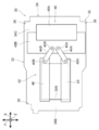
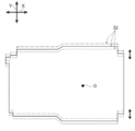
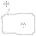
- FIG. 2 is an explanatory diagram illustrating an example of a camera body and a shutter unit of the digital camera according to the first embodiment.
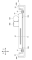
- FIG. 2 is an explanatory diagram illustrating an example of a camera body, an image sensor, and the like of the digital camera according to the first embodiment.
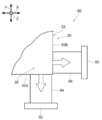
- FIG. 2 is a configuration diagram illustrating an example of a shutter unit according to the first embodiment.
- FIG. 2 is an explanatory diagram illustrating an example of an arrangement state of a camera body and a shutter unit in an optical axis direction according to the first embodiment.
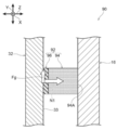
- FIG. 4 is a cross-sectional view illustrating an example of a state where a screw member is fastened to the camera body according to the first embodiment.
- FIG. 3 is an explanatory diagram illustrating an example of a state in which the entire shutter unit according to the first embodiment moves in a Y direction.
- FIG. 3 is an explanatory diagram illustrating an example of a state in which the entire shutter unit according to the first embodiment rotates around a center of gravity.
- FIG. 5 is an explanatory diagram illustrating an example of a camera body and a shutter unit of a digital camera according to a second embodiment.
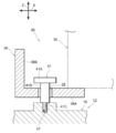
- FIG. 13 is a partially enlarged cross-sectional view illustrating an example of a part of a camera body and a part of a shutter unit of a digital camera according to a fifth embodiment.
- FIG. 14 is an explanatory diagram illustrating an example of a part of a shutter unit and a stepped screw of a digital camera according to a fifth embodiment. It is explanatory drawing which shows an example of the state which the sponge member which concerns on 5th Embodiment applies a frictional force with respect to a frame member.
- FIG. 15 is a partially enlarged cross-sectional view illustrating an example of a part of a camera body and a part of a shutter unit of a digital camera according to a modification of the sixth embodiment.
- FIG. 1 shows a digital camera 10 as an example of an imaging device according to the first embodiment.
- the digital camera 10 includes a camera body 12, a photographic lens unit 17 (see FIG. 2), an image sensor 20 (see FIG. 2), a shutter unit 30, a correction unit 50 (see FIG. 2), and a plurality of elastic members. And six coil springs 60 as an example.
- the camera body 12 is an example of the apparatus body.
- the camera body 12 includes a cover member 14 formed in a hollow box shape, and a base member 16 provided inside the cover member 14.
- the camera body 12 is provided with a liquid crystal monitor (not shown), a plurality of buttons, and a dial.
- the outer shape of a main part of the camera body 12 is formed in a rectangular shape when viewed from the optical axis direction of light from a subject (not shown). A part of the camera body 12 projects in a mountain shape.
- the longitudinal direction of the camera body 12 is referred to as an X direction
- the short direction of the camera body 12 is referred to as a Y direction
- the optical axis direction of light is referred to as a Z direction.
- the X, Y, and Z directions are orthogonal to each other.
- the arrangement state of the camera body 12 in the X direction along the horizontal direction is referred to as the lateral posture state of the digital camera 10.
- the arrangement state of the camera body 12 along the vertical direction in which the X direction is orthogonal to the horizontal direction is referred to as the vertical posture state of the digital camera 10.
- the cover member 14 is divided into two in the Z direction with a dividing line (not shown) as a boundary.
- the cover member 14 includes a front cover member 14A on the subject side (not shown) in the Z direction and a rear cover member 14B on the image sensor 20 side in the Z direction (see FIG. 2).
- the base member 16 is made of, for example, a sheet metal having a thickness direction in the Z direction.
- the base member 16 is fastened to the front cover member 14A using a plurality of screws 19 in a state where the base member 16 is stacked on the back surface of the front cover member 14A.
- a through-hole (not shown) penetrating the base member 16 in the Z direction is formed in a part of the base member 16. The size of the through hole does not affect the incidence of light from the subject.
- the six upright portions 15 protruding toward the image sensor 20 are provided upright.
- the six upright portions 15 are arranged above and below the base member 16 in the Y direction with an interval in the X direction when viewed from the Z direction.
- the six upright portions 15 are arranged with the Y direction as the thickness direction.
- the outer shapes of the six upright portions 15 are square when viewed from the Y direction.
- FIG. 2 schematically shows a state in which the inside of the digital camera 10 is viewed from the subject side in the Z direction.
- a shutter button 18 is provided on one side of the camera body 12 with respect to the center in the X direction and above the center with respect to the center in the Y direction.
- an image sensor 20 which will be described later, a control unit 24 for controlling the operation of each unit of the digital camera 10, an acceleration sensor 26, an angular velocity sensor 28, and a correction unit 50 are provided inside the camera body 12, inside the camera body 12, an image sensor 20, which will be described later, a control unit 24 for controlling the operation of each unit of the digital camera 10, an acceleration sensor 26, an angular velocity sensor 28, and a correction unit 50 are provided. I have.
- the control unit 24 is an example of a computer, and includes a CPU (Central Processing Unit) (not shown), a storage unit, and a circuit board.
- CPU Central Processing Unit
- the acceleration sensor 26 detects the acceleration of the translation movement of the digital camera 10 in the XY plane when the shutter button 18 is pressed.
- the angular velocity sensor 28 detects the angular velocity of the rotational movement of the digital camera 10 when the shutter button 18 is pressed. The information on the acceleration and the angular velocity is sent to the control unit 24.
- the photographing lens unit 17 shown in FIG. 2 is integrated with the camera body 12.
- the photographing lens unit 17 includes a lens (not shown), and forms an optical image ZA on an image sensor 20 described later.
- the optical image ZA is shown as a human figure as an example.
- the imaging device 20 is configured using, for example, a charge coupled device (CCD) image sensor.
- CCD charge coupled device
- the image sensor 20 is not limited to a CCD image sensor, and may be configured by another image sensor such as a CMOS (Complementary Metal-Oxide-Semiconductor) image sensor.
- the image sensor 20 includes an image forming surface 21 on which the incident light forms the optical image ZA.
- the imaging plane 21 is an example of an imaging plane. When viewed from the Z direction, the imaging surface 21 is formed in a rectangular shape with the X direction as a longitudinal direction and the Y direction as a lateral direction, for example.
- the image sensor 20 is supported by a correction unit 50 described below with the image plane 21 arranged along the XY plane. In other words, the image sensor 20 is provided on the camera body 12.
- the imaging surface 21 of the image sensor 20 is orthogonal to (or orthogonal to) the optical axis K of the light that forms the optical image ZA.
- the shutter unit 30 shown in FIG. 3 is provided in the camera body 12 (see FIG. 1). Specifically, the shutter unit 30 is configured as a focal plane shutter. The shutter unit 30 is disposed between the imaging lens unit 17 (see FIG. 2) and the image sensor 20 (see FIG. 2) in the Z direction, and controls the amount of light incident on the image sensor 20. It has a function to adjust. Further, the shutter unit 30 has a frame member 32 as an example of a support member, and a shutter member 42.
- the frame member 32 shown in FIG. 1 has, as an example, a main body portion 34 constituting a main part of the frame member 32, and a bracket portion 38 fixed to the main body portion 34.
- the frame member 32 is housed in the camera body 12 as an example.
- the main body 34 shown in FIG. 3 is formed in a box shape having a thickness direction in the Z direction. In other words, the main body 34 extends along the XY plane. Further, as an example, when viewed from the Z direction, the main body 34 is formed in a polygonal shape having a plurality of corners 35 including three right-angled corners 36. Further, as an example, when viewed from the Z direction, the main body 34 is provided with an opening 34A penetrating the main body 34 in the Z direction, a peripheral portion 34B surrounding the opening 34A, and a driving unit 48 described later. And a mounting portion 34C. A guide portion (not shown) that guides a leading curtain member 43 and a trailing curtain member 46 described later in the Y direction is formed on the peripheral portion 34B. 3 does not show the camera body 12 and the bracket 38 (see FIG. 1).
- the bracket portion 38 shown in FIG. 4 has a flat fixing portion 38A along the XY plane, and a plurality of upright wall portions 38B raised in the Z direction at the periphery of the fixing portion 38A.
- the fixing portion 38A is fixed to the main body 34 using screws (not shown) in a state where the fixing portion 38A is superimposed on the main body 34 from the subject side in the Z direction.
- the fixing portion 38A has four through holes 39 (see FIG. 1) penetrated in the Z direction.
- the through hole 39 is formed in a square shape when viewed from the Z direction.
- the bracket portion 38 shown in FIG. 1 extends outward in the X direction and the Y direction from the main body portion 34 when viewed from the Z direction.
- the plurality of upright wall portions 38B are plate-shaped wall portions extending in the Z direction with the X direction or the Y direction being the thickness direction. Further, a part of the plurality of upright wall portions 38B is arranged to face the six upright plate portions 15 in the Y direction.
- the shaft portion 41B of the screw member 41 is inserted in the Z direction into the through hole 39 shown in FIG.
- the screw member 41 includes a disk-shaped head 41A, a cylindrical shaft 41B extending in one direction from the center of the head 41A, and a male screw 41C formed on the tip side of the shaft 41B. Having. In each of the drawings, illustration of a cross groove for rotating the head 41A is omitted.
- the size of the head 41A is such that it can contact the periphery of the through hole 39 in the Z direction.
- the thickness of the shaft portion 41B is such that there is a gap between the peripheral portion of the through hole 39 and the X and Y directions (see FIG. 1) when the shaft portion 41B is passed through the through hole 39 in the Z direction.
- the male screw portion 41C is fastened to the female screw portion 47 formed on the base member 16.
- the screw member 41 restricts the shutter unit 30 from being excessively displaced in the Z direction with respect to the base member 16 (camera body 12).
- the screw member 41 gives a degree of freedom that the shutter unit 30 can move in the X direction and the Y direction with respect to the camera body 12 at the portion where the through hole 39 is formed. Further, when the shutter unit 30 is unnecessarily moved in the X direction and the Y direction, the screw member 41 comes into contact with the peripheral edge of the through hole 39, thereby restricting excessive movement of the shutter unit 30. have.
- the shutter member 42 shown in FIG. 3 is supported by the frame member 32.
- the shutter member 42 includes, for example, a front curtain member 43, a link member 44A, a connection pin 45A, a rear curtain member 46, a link member 44B, and a connection pin 45B.
- a drive unit 48 for driving the front curtain member 43 and the rear curtain member 46 is included in the shutter member 42.
- the front curtain member 43 is made of a curtain material whose length in the X direction is equal to or longer than the length of the opening 34A in the X direction, and is arranged with the Z direction as the thickness direction.
- One end of the link member 44A in the longitudinal direction is connected to one end of the front curtain member 43 in the X direction by a connection pin 45A whose axial direction is in the Z direction.
- the other end in the longitudinal direction of the link member 44A is connected to the attached portion 34C by another connecting pin 45A.
- the rear curtain member 46 is made of a curtain material whose length in the X direction is equal to or longer than the length of the opening 34A in the X direction, and is arranged with the Z direction as the thickness direction.
- One end in the longitudinal direction of the link member 44B is connected to one end in the X direction of the rear curtain member 46 by a connecting pin 45B whose axial direction is in the Z direction.
- the other end in the longitudinal direction of the link member 44B is connected to the attached portion 34C by another connecting pin 45B.
- the rear curtain member 46 is disposed above the front curtain member 43 in the Y direction.
- the front curtain member 43 and the rear curtain member 46 are movable in the Y direction by being guided by the above-described guide portions.
- the Y direction is an example of a direction orthogonal to the optical axis K and a moving direction in which the shutter member 42 moves.
- the X direction is an example of an orthogonal direction orthogonal to the moving direction.
- the drive unit 48 includes a motor 48A that is rotationally driven by energization from a power supply unit (not illustrated), and a drive transmission unit 48B that includes a plurality of gears (not illustrated) that transmits the rotational drive of the motor 48A to the link members 44A and 44B. It is composed of As an example, when the shutter button 18 (see FIG. 2) is pressed, the driving unit 48 moves the front curtain member 43 and the rear curtain member 46 upward in the Y direction, and then moves the front curtain member 43 to Y position. The rear curtain member 46 is moved downward in the Y direction, and then the rear curtain member 46 is moved downward in the Y direction. In the shutter unit 30, the exposure time of the digital camera 10 (see FIG. 1) is adjusted by changing the slit interval in the Y direction between the front curtain member 43 and the rear curtain member 46 moved in the Y direction.
- the center of gravity G is the point of application of the resultant force of gravity acting on each part of the shutter unit 30.
- the center of gravity G is a line of action of the tension of the thread when one point of the shutter unit 30 is suspended by a thread and stopped, and the tension of the thread when the other point of the shutter unit 30 is suspended and suspended by the thread. Is determined as the intersection with the action line of In the present embodiment, as an example, a description will be given assuming that the center of gravity G is located on the attached portion 34C when the shutter unit 30 is viewed from the Z direction.
- a line extending along the Y direction passing through the center of gravity G is referred to as a virtual straight line A1.
- the virtual straight line A1 is orthogonal to the Z direction which is the optical axis direction.
- the virtual straight line A1 is orthogonal to the optical axis K when viewed from the X direction.
- the correction unit 50 illustrated in FIG. 2 is an example of a camera shake correction unit, and is provided in the camera body 12.
- the correction unit 50 corrects the camera shake amount of the digital camera 10 by moving the image sensor 20 in the X direction and the Y direction, for example.
- the correction unit 50 has a base plate 52, a Y-direction slider 54, a Y-direction actuator 56, an X-direction slider 58, and an X-direction actuator 62.
- the base plate 52 is formed in a plate shape having a thickness direction in the Z direction.
- the image sensor 20 is fixed to the base plate 52.
- the Y-direction slider 54 supports the base plate 52 movably in the Y direction.
- the Y direction actuator 56 moves the base plate 52 in the Y direction.
- the X-direction slider 58 supports the base plate 52, the Y-direction slider 54, and the Y-direction actuator 56 movably in the X direction.
- the X direction actuator 62 moves the X direction slider 58 in the X direction.
- the control unit 24 drives the X-direction actuator 62 and the Y-direction actuator 56 in a direction to cancel the camera shake, and moves the image sensor 20 in the X direction and the Y direction. Let it. By moving the image sensor 20, a shift (corresponding to the amount of camera shake) of the optical image ZA on the image plane 21 of the image sensor 20 is corrected.
- the camera shake may be corrected based on the detection results of the acceleration sensor 26 and the angular velocity sensor 28.
- ⁇ Coil spring> 6 are distinguished from the coil springs 60A, 60B, 60C, 60D, 60E, and 60F.
- the coil springs 60 ⁇ / b> A, 60 ⁇ / b> B, 60 ⁇ / b> C, 60 ⁇ / b> D, 60 ⁇ / b> E, and 60 ⁇ / b> F are in contact with the camera body 12 (see FIG. 1) and the frame member 32 with the Y direction as the axial direction (extension and contraction direction). (Restoring force).
- the coil spring 60A is disposed on one side (the side where the opening 34A is disposed) with respect to the virtual straight line A1 and below the Y direction when viewed from the Z direction.
- One end in the axial direction of the coil spring 60A is in contact with the upright wall 38B (see FIG. 1).
- illustration of the standing wall portion 38B is omitted.
- the other end in the axial direction of the coil spring 60 ⁇ / b> A is in contact with the upright portion 15.
- the coil spring 60A is arranged, for example, in a compressed state, and applies a load F1 [N] (see FIG. 7) to the frame member 32 toward the upper side in the Y direction.
- a virtual point at which the central axis of the coil spring 60A intersects with the standing wall portion 38B is defined as a point A.
- the distance in the X direction from the virtual straight line A1 to the point A is defined as a distance L1 [mm] (see FIG. 7).
- the coil spring 60B is disposed on the other side (on the side where the motor 48A is disposed) with respect to the virtual straight line A1 and below the Y direction when viewed from the Z direction.
- One end in the axial direction of the coil spring 60B is in contact with the upright wall 38B (see FIG. 1).
- the other end in the axial direction of the coil spring 60 ⁇ / b> B is in contact with the upright plate 15.
- the coil spring 60B is arranged, for example, in a compressed state, and applies a load F2 [N] (see FIG. 7) to the frame member 32 upward in the Y direction.
- a virtual point at which the central axis of the coil spring 60B intersects with the standing wall portion 38B is defined as a point B.
- the distance in the X direction from the virtual straight line A1 to the point B is defined as a distance L2 [mm] (see FIG. 7).
- the coil spring 60C is disposed on one side of the virtual straight line A1 and on the upper side in the Y direction when viewed from the Z direction. That is, the coil spring 60C is arranged at a distance from the coil spring 60A in the Y direction. One end in the axial direction of the coil spring 60C is in contact with the upright wall 38B (see FIG. 1). The other end in the axial direction of the coil spring 60C is in contact with the upright plate 15.
- the coil spring 60C is arranged, for example, in a compressed state, and applies a load F3 [N] (see FIG. 7) to the frame member 32 downward in the Y direction.
- a virtual point at which the center axis of the coil spring 60C intersects with the vertical wall portion 38B is defined as a point C.
- the distance in the X direction from the virtual straight line A1 to the point C is defined as a distance L3 [mm] (see FIG. 7).
- the coil spring 60D is disposed on the other side of the virtual straight line A1 and above the Y direction when viewed from the Z direction. That is, the coil spring 60D is arranged at a distance from the coil spring 60B in the Y direction. One end in the axial direction of the coil spring 60D is in contact with the upright wall 38B (see FIG. 1). The other end in the axial direction of the coil spring 60 ⁇ / b> D is in contact with the standing plate portion 15.
- the coil spring 60D is arranged, for example, in a compressed state, and applies a load F4 [N] (see FIG. 7) to the frame member 32 toward the lower side in the Y direction.
- a virtual point at which the center axis of the coil spring 60D intersects with the standing wall portion 38B is defined as a point D.
- the distance in the X direction from the virtual straight line A1 to the point D is defined as a distance L4 [mm] (see FIG. 7).
- the coil spring 60E is disposed on the virtual straight line A1 and below the Y direction when viewed from the Z direction. One end in the axial direction of the coil spring 60E is in contact with the upright wall 38B (see FIG. 1). The other axial end of the coil spring 60 ⁇ / b> E is in contact with the upright plate 15.
- the coil spring 60E is arranged, for example, in a compressed state, and applies a load F5 [N] (see FIG. 7) to the frame member 32 toward the upper side in the Y direction.
- a virtual point at which the center axis of the coil spring 60E intersects with the standing wall portion 38B is defined as a point E.
- the distance in the X direction from the virtual straight line A1 to the point E is 0 [mm].
- the coil spring 60F is disposed on the virtual straight line A1 and above the Y direction when viewed from the Z direction. That is, the coil springs 60E and 60F are arranged on the virtual straight line A1 with an interval in the Y direction. One end of the coil spring 60F in the axial direction is in contact with the upright wall 38B (see FIG. 1). The other axial end of the coil spring 60 ⁇ / b> E is in contact with the upright plate 15.
- the coil spring 60F is arranged, for example, in a compressed state, and applies a load F6 [N] (see FIG. 7) to the frame member 32 downward in the Y direction.
- a virtual point at which the central axis of the coil spring 60F intersects with the standing wall portion 38B is defined as a point F.
- the distance in the X direction from the virtual straight line A1 to the point F is 0 [mm].
- the coil springs 60A, 60B, 60C, 60D, 60E, and 60F are disposed at least on one side and the other side in the X direction with respect to the virtual straight line A1 when viewed from the Z direction, and the upright plate portion 15 and the upright wall portion 38B (see FIG. 1).
- the coil springs 60A, 60B, 60C, 60D, 60E, and 60F are arranged in the Y direction with the frame member 32.
- the Y direction is the moving direction of the shutter member 42 as described above.
- the coil springs 60A and 60B are an example of a first elastic member.
- the coil springs 60C and 60D are examples of a second elastic member.
- F5 F6.
- the length of the arrow for each load is not related to the magnitude of the load.
- the loads F1, F2, F3, F4, F5, F6 and the distances L1, L2, L3, L4 are set in a range in which the rotation of the shutter unit 30 around the center of gravity G within an allowable range is not restricted. I have.
- the spring constant [N / mm] of the coil springs 60A, 60B, 60C, and 60D may be changed.
- the method of changing the spring constant include a method of changing the thickness of the spring, a method of changing the material of the spring, and a method of changing the winding diameter (inner diameter) of the spring.
- the frame member 32 is supported in the Y direction by contacting the six coil springs 60 with the frame member 32, so that the frame member 32 does not have to be rigidly connected to the camera body 12. . Since the frame member 32 is not rigidly connected to the camera main body 12, transmission of an impact force from the shutter unit 30 to the camera main body 12 can be suppressed as compared with a configuration in which the frame member 32 is rigidly connected. In other words, the digital camera 10 has a configuration in which the movement of the frame member 32 is allowed within the allowable range by the six coil springs 60, so that the transmission of the impact force from the shutter unit 30 to the camera body 12 is suppressed. be able to.
- a plurality of coil springs 60 are arranged on one side and the other side in the X direction with respect to the virtual straight line A1 passing through the center of gravity G. Since the plurality of coil springs 60 are disposed on one side and the other side with respect to the virtual straight line A1, the rotation of the shutter unit 30 (frame member 32) about the center of gravity G may be biased in one direction. Is suppressed. Since the biased rotation of the shutter unit 30 is suppressed, the contact between the shutter unit 30 and the camera body 12 (see FIG. 1) is suppressed, so that the transmission of the impact force from the shutter unit 30 to the camera body 12 is suppressed. can do.
- the transmission of the impact force from the shutter unit 30 to the camera body 12 is suppressed, so that the impact force transmitted to the correction unit 50 (see FIG. 2) is reduced. Therefore, erroneous correction in the correction unit 50 can be suppressed.
- the erroneous correction in the correction unit 50 means, for example, a correction error that causes vignetting of the optical image ZA (see FIG. 2), displacement of the optical image ZA, reduction in resolution of the optical image ZA, and the like.
- the coil springs 60E and 60F are arranged on the virtual straight line A1.
- the impact force acting on the shutter unit 30 near the center of gravity G is reduced.
- the impact force acting on the correction unit 50 is suppressed from being increased. Can be suppressed.
- a plurality of coil springs 60 are arranged in the direction in which the frame member 32 moves with the movement of the shutter member 42 (see FIG. 3). That is, since the moving direction of the frame member 32 and the direction in which the coil spring 60 elastically deforms are aligned, the movement of the frame member 32 can be suppressed without increasing the number of coil springs 60 more than necessary.
- the load of the plurality of coil springs 60 is smaller when the distance from the virtual straight line A1 is longer than when the distance is shorter than the virtual straight line A1.
- the amount of rotation of the unit 30 is reduced. That is, rotation of the shutter unit 30 around the center of gravity G can be suppressed.
- the coil spring 60 (see FIG. 6) can uniformly resist the impact force caused by the movement of the shutter member 42 (see FIG. 3) on one side and the other side with respect to the virtual straight line A1. . Since the coil spring 60 uniformly resists, the rotation of the shutter unit 30 around the center of gravity G can be suppressed from being biased to one side.
- the frame member 32 is formed in a polygonal shape when viewed from the Z direction.
- the contact area between the frame member 32 and the coil spring 60 is increased. can do.
- the frame member 32 is housed in the camera body 12. That is, since a part of the camera main body 12 and the shutter unit 30 are arranged so as to overlap in the Z direction, the size of the digital camera 10 in the Z direction is made smaller than in a configuration in which the shutter unit 30 is not housed in the camera main body 12. can do.
- the coil springs 60 are disposed on one side and the other side in the X direction with respect to the virtual straight line A1 when viewed from the Z direction. Then, by supporting the frame member 32 on the camera body 12 via the coil spring 60, vibration of the shutter unit 30 is suppressed. That is, since the coil spring 60 is in contact with the frame member 32, the transmission of the impact force from the shutter unit 30 to the camera body 12 is suppressed, that is, the impact force transmitted to the correction unit 50 is reduced. Erroneous correction in the unit 50 can be suppressed.
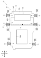
- FIG. 10 shows a digital camera 70 as an example of the imaging device according to the second embodiment.
- the digital camera 70 has a configuration in which four upright portions 72 and four coil springs 74 are added to the shutter unit 30 on both sides in the X direction in the digital camera 10 (see FIG. 1) described above. Have been.
- the basic configuration other than the four upright portions 72 and the four coil springs 74 is the same as that of the digital camera 10.
- the four standing plate portions 72 stand on the back surface in the Z direction of the front cover member 14A and on one side and the other side in the X direction with respect to the shutter unit 30 from the base member 16 toward the image sensor 20 (see FIG. 2). Has been established.
- the four upright portions 72 are arranged on the one side and the other side in the X direction with respect to the frame member 32 at intervals in the X direction when viewed from the Z direction.
- the four standing plate portions 72 are arranged with the X direction as the thickness direction.
- the outer shapes of the four standing plate portions 72 are square when viewed from the X direction.
- the four coil springs 74 are an example of a plurality of auxiliary elastic members.
- the four coil springs 74 are distinguished from the coil springs 74A, 74B, 74C, 74D.
- the coil springs 74 ⁇ / b> A, 74 ⁇ / b> B, 74 ⁇ / b> C, and 74 ⁇ / b> D are in contact with the upright portion 72 and the frame member 32 with the X direction as the axial direction (extension and contraction direction), and apply a load (restoring force) toward the frame member 32.
- the coil springs 74A and 74B are an example of a third elastic member, and are arranged at intervals in the X direction.
- the coil springs 74C and 74D are an example of a fourth elastic member, and are arranged at intervals in the X direction.
- a virtual straight line extending in the Y direction through the center of gravity G of the shutter unit 30 when viewed from the Z direction in the horizontal posture state of the digital camera 70 shown in FIG. 11 is referred to as a first virtual straight line A1.
- a virtual straight line passing through the center of gravity G and extending in the X direction is referred to as a second virtual straight line A2.
- the virtual straight line passing through the center of gravity G has a first virtual straight line A1 and a second virtual straight line A2.
- the first virtual straight line A1 and the second virtual straight line A2 are orthogonal to the Z direction which is the optical axis direction.
- the second virtual straight line A2 is orthogonal to the optical axis K when viewed from the Y direction.
- the coil spring 74A is arranged on one side (lower side) with respect to the second virtual straight line A2 and on one side in the X direction with respect to the frame member 32 when viewed from the Z direction.
- One axial end of the coil spring 74A is in contact with the bracket 38 (see FIG. 10).
- the illustration of the bracket portion 38 is omitted.
- the other axial end of the coil spring 74 ⁇ / b> A is in contact with the standing plate 72.
- the coil spring 74A is arranged, for example, in a compressed state, and applies a load FA [N] (see FIG. 12) to the frame member 32 toward the other side in the X direction.
- a virtual point at which the central axis of the coil spring 74A and the bracket 38 intersect is referred to as a point P.
- the distance in the Y direction from the second virtual straight line A2 to the point P is defined as a distance LA [mm] (see FIG. 12).
- the coil spring 74B is disposed on the other side (upper side) with respect to the second virtual straight line A2 and on one side in the X direction with respect to the frame member 32 when viewed from the Z direction.
- One end of the coil spring 74B in the axial direction is in contact with the bracket 38 (see FIG. 10).
- the other end in the axial direction of the coil spring 74 ⁇ / b> B is in contact with the upright plate 72.
- the coil spring 74B is arranged in a compressed state, for example, and applies a load FB [N] (see FIG. 12) to the frame member 32 toward the other side in the X direction.
- a virtual point at which the central axis of the coil spring 74B and the bracket 38 intersect is referred to as a point Q.
- the distance in the Y direction from the second virtual straight line A2 to the point Q is defined as a distance LB [mm] (see FIG. 12).
- the coil spring 74C is arranged on one side (lower side) with respect to the second virtual straight line A2 and on the other side in the X direction with respect to the frame member 32 when viewed from the Z direction.
- One end of the coil spring 74C in the axial direction is in contact with the bracket 38 (see FIG. 10).
- the other end in the axial direction of the coil spring 74 ⁇ / b> C is in contact with the upright plate portion 72.
- the coil spring 74C is arranged, for example, in a compressed state, and applies a load FC [N] (see FIG. 12) to the frame member 32 toward one side in the X direction.
- a virtual point at which the central axis of the coil spring 74C and the bracket 38 intersect is referred to as a point R.
- the distance in the Y direction from the second virtual straight line A2 to the point R is defined as a distance LC [mm] (see FIG. 12).
- the coil spring 74D is arranged on the other side (upper side) with respect to the second virtual straight line A2 and on the other side in the X direction with respect to the frame member 32 when viewed from the Z direction.
- One axial end of the coil spring 74D is in contact with the bracket 38 (see FIG. 10).
- the other end in the axial direction of the coil spring 74D is in contact with the upright plate portion 72.
- the coil spring 74D is arranged, for example, in a compressed state, and applies a load FD [N] (see FIG. 12) to the frame member 32 toward one side in the X direction.
- a virtual point at which the central axis of the coil spring 74D and the bracket 38 intersect is referred to as a point S.
- the distance in the Y direction from the second virtual straight line A2 to the point S is defined as a distance LD [mm] (see FIG. 12).
- FIG. 12 schematically shows the arrangement of the shutter unit 30, the six coil springs 60 (see FIG. 11), and the four coil springs 74 (see FIG. 11) when viewed from the Z direction.
- the loads FA, FB, FC, and FD and the distances LA, LB, LC, and LD are set within a range in which the rotation of the shutter unit 30 around the center of gravity G within an allowable range is not restricted.
- (FA ⁇ LA) + (FB ⁇ LB) (FC ⁇ LC) + (FD ⁇ LD).
- the spring constant [N / mm] of the coil springs 74A, 74B, 74C, and 74D may be changed.
- the method of changing the spring constant include a method of changing the thickness of the spring, a method of changing the material of the spring, and a method of changing the winding diameter (inner diameter) of the spring.
- the shutter unit 30 When the use state of the digital camera 70 shown in FIG. 10 is changed from the horizontal posture state to the vertical posture state, the shutter unit 30 is moved by its own weight in the X direction (vertical direction) with respect to the original position. Trying to go down below.
- the loads (restoring forces) of the plurality of coil springs 74 act as resistance against the own weight of the shutter unit 30, it is possible to suppress the shutter unit 30 from being lowered downward in the X direction.
- each coil spring 74 is arranged on the upper and lower sides in the Y direction with respect to the second virtual straight line A2 passing through the center of gravity G.
- the rotation of the shutter unit 30 about the center of gravity G is prevented from being biased in one direction. Since the biased rotation of the shutter unit 30 is suppressed, the contact between the shutter unit 30 and the camera body 12 (see FIG. 10) is suppressed, so that when the shutter unit 30 is operated, the shutter unit 30 is moved from the camera body. 12 can be suppressed from being transmitted.
- the transmission of the impact force from the shutter unit 30 to the camera body 12 is suppressed, the impact force transmitted to the correction unit 50 (see FIG. 2) is reduced, so that erroneous correction in the correction unit 50 is suppressed. be able to.
- the coil spring 74 can uniformly resist the one side and the other side with respect to the second virtual straight line A2, so that the rotation of the shutter unit 30 about the center of gravity G is prevented from being biased in one direction. can do.
- FIG. 13 shows a part of a digital camera 80 as an example of the imaging device according to the third embodiment.
- the digital camera 80 has a configuration in which eight standing plate portions 82 and eight rubber members 84 are added to the digital camera 70 (see FIG. 10) described above.
- the basic configuration other than the standing plate portion 82 and the rubber member 84 is the same as that of the digital camera 70.
- FIG. 13 shows only the eight upright portions 82 formed on the camera body 12 (see FIG. 1), and does not show other configurations of the camera body 12.
- the eight standing plate portions 82 are provided on the back surface in the Z direction of the front cover member 14A (see FIG. 1), and on one side, the other side in the X direction and the upper and lower sides in the X direction with respect to the shutter unit 30, the image sensor 20 ( (See FIG. 2). Further, among the eight upright portions 82, four upright portions 82 are arranged to face the frame member 32 in the Y direction, and the remaining four upright portions 82 are arranged to face the frame member 32 in the X direction. I have.
- the outer shapes of the eight standing plate portions 72 are square when viewed from the X direction or the Y direction.
- the eight rubber members 84 are an example of a plurality of damping members.
- the eight rubber members 84 are made of, for example, silicon rubber.
- the eight rubber members 84 are all formed in a rectangular parallelepiped shape, but some of the sizes are different in accordance with the size of the location.
- the four rubber members 84 are in contact with the upright plate portion 82 and the frame member 32 with the X direction as the compression direction.
- the remaining four rubber members 84 are in contact with the upright plate portion 82 and the frame member 32 with the Y direction as the compression direction.
- the eight rubber members 84 are sandwiched between the eight upright portions 82 and the frame member 32, and have a function of attenuating the movement (vibration) of the shutter unit 30 in the X and Y directions.
- the eight rubber members 84 include, for example, one along the X direction in each of the four virtual regions SA, SB, SC, and SD defined by the first virtual straight line A1 and the second virtual straight line A2. One is arranged along the Y direction.
- FIG. 14 shows a state where one corner 35 of the frame member 32 is enlarged.
- the corner 35 is formed by a side surface 35A along the XZ plane and a side surface 35B along the YZ plane, for example.
- the rubber member 84 compressed in the Y direction is in contact with the side surface 35A.
- the rubber member 84 compressed in the X direction is in contact with the side surface 35B.
- the two rubber members 84 are in contact with the side surface 35A or the side surface 35B forming the corner 35 from different directions.
- the transmission of the impact force from the shutter unit 30 to the camera body 12 is suppressed by the vibration of the shutter unit 30 being attenuated by the eight rubber members 84. Since the transmission of the impact force from the shutter unit 30 to the camera body 12 is suppressed, the impact force transmitted to the correction unit 50 (see FIG. 2) is reduced, so that erroneous correction in the correction unit 50 can be suppressed. it can.
- the rubber member 84 contacts the two side surfaces 35A and 35B forming the corner 35 from different directions when viewed from the Z direction.
- the plurality of rubber members 84 that come into contact with the corner 35 from different directions attenuate the vibration in the X direction and the Y direction. Will be. That is, the amplitude of the vibration of the shutter unit 30 can be reduced regardless of the vibration direction of the frame member 32.
- FIG. 16 shows a part of a digital camera 90 as an example of the imaging device according to the fourth embodiment.
- the digital camera 90 has a configuration in which four sponge members 92 as an example of a damping member and a friction member are added to the digital camera 80 described above (see FIG. 13).
- the basic configuration other than the sponge member 92 is the same as that of the digital camera 80.
- the sponge member 92 shown in FIG. 17 has, as an example, a columnar sponge body 94 having the Z direction as a central axis direction, and a sliding sheet 96 fixed to one end surface of the sponge body 94 in the Z direction.
- Each sponge member 92 is, for example, arranged at four corners of the frame member 32 when viewed from the Z direction.
- the sponge member 92 is sandwiched in the Z direction by the frame member 32 and the base member 16 on the side of the image sensor 20 (see FIG. 2). Specifically, the other end surface 94A in the Z direction of the sponge body 94 is adhered to the base member 16.
- the rubbing sheet 96 is in contact with the back surface 33 of the frame member 32 on the image sensor 20 side in the Z direction. It is assumed that a normal force N1 [N] is acting on the sponge body 94 and the rubbing sheet 96 in the Z direction, and the static friction coefficient at the interface between the frame member 32 and the rubbing sheet 96 is ⁇ .
- FIG. 18 shows a main part of a digital camera 100 as an example of the imaging apparatus according to the fifth embodiment.
- the digital camera 100 includes a camera body 102, a photographic lens unit 17 and an image sensor 20 (see FIG. 20), a shutter unit 140, a correction unit 50 (see FIG. 20), and four elastic members as examples. And a spring unit 192 (see FIG. 21). Further, the digital camera 100 has a rubber member 202 (see FIG. 21) as an example of a shock absorbing member, a sponge member 204 (see FIG. 19) as an example of a sliding member, and a stepped member as an example of a fastening member. A screw 208 (see FIG. 21) is provided.
- the camera body 102 shown in FIG. 18 is an example of the apparatus body. Further, the camera body 102 includes a cover member 104 formed in a hollow box shape, and a base member 110 provided inside the cover member 104. The camera body 102 is provided with a liquid crystal monitor (not shown), a plurality of buttons, and a dial. The outer shape of the main part of the camera body 102 is formed in a rectangular shape when viewed from the optical axis direction of light from a subject (not shown).
- the longitudinal direction of the camera body 102 is referred to as an X direction, and the short direction of the camera body 102 is referred to as a Y direction.
- the optical axis direction of light is referred to as a Z direction.
- the X, Y, and Z directions are orthogonal to each other.
- the arrangement state of the camera body 102 in the X direction along the horizontal direction is referred to as the lateral posture state of the digital camera 100.
- the arrangement state of the camera body 102 along the vertical direction in which the X direction is orthogonal to the horizontal direction is referred to as the vertical posture state of the digital camera 100.
- the Y direction is an example of a moving direction in which a shutter member 144 (see FIG. 21) described later moves in a direction orthogonal to the optical axis K (see FIG. 20).
- the X direction is an example of an orthogonal direction orthogonal to the moving direction.
- the cover member 104 is divided into two in the Z direction with a dividing line (not shown) as a boundary.
- the cover member 104 includes a front cover 105 on the object side (not shown) in the Z direction, and a rear cover 106 on the image sensor 20 side in the Z direction (see FIG. 20).
- the subject side is referred to as a front side
- the image sensor 20 side is referred to as a rear side.
- a through hole 105A is formed in a part of the front cover 105 so as to penetrate the front cover 105 in the Z direction and to receive light.
- the size of the through-hole 105A is a size that does not affect the incidence of light from the subject.
- two fastened portions 108 are formed on a part of the rear surface 105 ⁇ / b> B on the front cover 105.
- the two fastened portions 108 shown in FIG. 19 are arranged at an interval in the Y direction on the left side of the center in the X direction of the front cover 105 when viewed from the rear side in the Z direction. .
- the two fastened portions 108 protrude rearward from the front cover 105 in the Z direction.
- the fastened portion 108 is formed in a cylindrical shape whose axial direction is the Z direction.
- a female screw to which a male screw portion of a stepped screw 208 (see FIG. 21) is fastened is formed on the inner wall of the fastened portion 108.
- the base member 110 includes, for example, a frame member 112 and a main body member 124.
- the frame member 112 has a metal main frame 114 and a sub-frame 118 as an example.
- the main frame 114 overlaps with the central portion and the left portion of the front cover 105 in the X direction when viewed from the rear in the Z direction.
- the sub-frame 118 overlaps the right portion of the front cover 105 in the X direction when viewed from the rear in the Z direction.
- the main frame 114 is configured to include a flat portion 115 along the XY plane, and a plurality of upright portions 116 upright from a part of the outer edge portion of the flat portion 115 toward the rear side in the Z direction. I have.
- the plurality of upright portions 116 are disposed at the lower left of the flat portion 115 when viewed from the rear side in the Z direction, and the upright portion 116A having the Y direction as the thickness direction.
- an upright portion 116B having a thickness direction in the X direction and another upright portion 116C.
- the plurality of upright portions 116 are formed in a square shape when viewed from the thickness direction.
- Each of the uprights 116 has a cutout 117 that is recessed from the rear end toward the front side in the Z direction.
- the notch 117 is, for example, a linear portion 117A extending in the Z direction (see FIG. 18) when viewed from the X direction, and is widened in the Y direction at the front of the linear portion 117A with respect to the linear portion 117A. And a widened portion 117B (see FIG. 18).
- the main frame 114 is fastened to the front cover 105 using a plurality of screws (not shown) in a state where the main frame 114 is stacked on the back surface 105B from the rear side.
- a through hole 114A through which the light is incident is formed through the main frame 114 in the Z direction.
- the size of the through hole 114A is a size that does not affect the incidence of light from the subject.
- the sub-frame 118 is fastened to the front cover 105 using a plurality of screws (not shown) in a state where the sub-frame 118 is overlaid on the back surface 105B from the rear side.
- the sub-frame 118 includes a flat portion 121 extending in the Y direction along the XY plane, and three upright portions 122 standing upright from a part of an outer edge portion of the flat portion 121 toward the rear side in the Z direction. , And one standing plate portion 123.
- the flat portion 121 is formed with a fastening hole 165 to which a stepped screw 208 described later is fastened.
- the three standing plate portions 122 are formed in a square shape when viewed from the plate thickness direction.
- the three standing portions 122 are distinguished from the standing portion 122A, the standing portion 122B, and the standing portion 122C.
- the upright plate portion 122A is arranged at the upper end of the flat portion 121 with the Y direction as the plate thickness direction when viewed from the rear side in the Z direction.
- the upright plate portion 122B is arranged at the upper right of the flat portion 121 with the X direction as the plate thickness direction.
- the standing plate portion 122C is arranged at the lower right of the flat portion 121 with the X direction as the plate thickness direction.
- a cutout 117 is formed in each of the upright portions 122A, 122B, and 122C so as to be depressed from the rear end toward the front side in the Z direction.
- An upright portion 123 is disposed below the upright portion 122C in the Y direction.
- the main body member 124 is a member arranged on the rear side with respect to the main frame 114.
- the main body member 124 is made of resin, for example.
- the main body member 124 is configured to include a flat portion 125 extending in the X direction along the XY plane and a vertical wall portion 126 standing upright from the outer edge portion of the flat portion 125 toward the rear side in the Z direction. ing.
- a portion disposed at the lower left of the flat portion 125 with the Y direction as the thickness direction is referred to as a vertical wall portion 126A.
- two through holes 127 are formed at intervals in the Y direction and penetrate the flat portion 125 in the Z direction.
- the upright portion 116B and the upright portion 116C protrude rearward in the Z direction from the flat portion 125 through the through hole 127.
- two through holes 131 are formed at intervals in the Y direction and pass through the flat portion 125 in the Z direction.
- the two fastened portions 108 project rearward from the flat portion 125 through the through holes 131.
- the main body member 124 is fastened to the front cover 105 using a plurality of screws (not shown) in a state where the main body member 124 is stacked on the main frame 114 from the rear side.
- a through hole 129 that penetrates the main body member 124 in the Z direction and receives light is formed in a part of the main body member 124. The size of the through hole 129 does not affect the incidence of light from the subject.
- FIG. 20 schematically shows an example of a state in which the inside of the digital camera 100 (the rear cover 106 side) is viewed from the front side in the Z direction.
- a shutter button 18 is provided on one side of the camera body 102 with respect to the X direction center and on the upper side with respect to the Y direction center.
- an imaging element 20 inside the camera main body 102, an imaging element 20, a control unit 24 for controlling the operation of each unit of the digital camera 100, an acceleration sensor 26, an angular velocity sensor 28, and a correction unit 50 are provided inside the camera main body 102.
- the taking lens unit 17 is integrally attached to the camera body 102.
- the shutter unit 140 shown in FIG. 21 is provided in the camera body 102. Specifically, the shutter unit 140 is configured as a focal plane shutter. The shutter unit 140 is disposed between the photographing lens unit 17 (see FIG. 20) and the image sensor 20 (see FIG. 20) in the Z direction, and controls the amount of light incident on the image sensor 20. It has a function to adjust.
- the shutter unit 140 has a frame member 142 as an example of a support member, and a shutter member 144.
- the frame member 142 includes, for example, a main body 146 constituting a main part of the frame member 142, a left bracket 156 fixed to a left end of the main body 146, and a right bracket fixed to a right end of the main body 146. A part 159. Further, the frame member 142 is housed in the camera body 102.
- the main body 146 is formed in a box shape having the thickness direction in the Z direction.
- the main body 146 extends along the XY plane.
- the main body 146 is formed in a polygonal shape having a plurality of corners including a lower left corner 147 and an upper right corner 148 when viewed from the rear side in the Z direction as an example.
- the main body 146 when viewed from the Z direction, has an opening 146A that penetrates the main body 146 in the Z direction, a peripheral edge 146B surrounding the opening 146A, and a housing to which the driving unit 172 is attached. And an attachment portion 146C.
- a guide portion (not shown) that guides the front curtain member 43 and the rear curtain member 46 in the Y direction is formed on the peripheral edge portion 146B.
- the left bracket portion 156 includes, for example, a flat fixing portion 157 along the XY plane, and an upright wall portion 158 that is raised at the periphery of the fixing portion 157 toward the rear side in the Z direction.
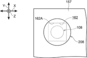
- the fixing portion 157 is fixed to the main body 146 by using a screw 151 in a state where the fixing portion 157 is overlapped with the main body 146 from the front side in the Z direction. Further, the fixing portion 157 has two through holes 162 (see FIG. 23B) penetrating the fixing portion 157 (frame member 142) in the Z direction.
- the through hole 162 shown in FIG. 23B is formed in a square shape when viewed from the Z direction.
- the size of the through hole 162 is larger than the size corresponding to the outer diameter of the fastened portion 108.
- the distance between the two through holes 162 in the Y direction is substantially equal to the distance between the two fastened portions 108 in the Y direction.
- the part which becomes a wall in the through-hole 162 is called hole wall 162A.
- the standing wall portion 158 shown in FIG. 21 includes a standing wall portion 158A arranged at the lower end of the fixed portion 157 with the Y direction as the thickness direction, and a standing wall portion 158B arranged at the left end of the fixed portion 157 with the X direction as the thickness direction. It is comprised including.
- a cutout 117 is formed in the upright wall 158A and the upright wall 158B.
- the right side portion of the upright wall portion 158A is disposed to face the upright plate portion 116A in the Y direction.
- the left portion of the standing wall portion 158A is disposed to face the vertical wall portion 126A in the Y direction.
- the upright wall portion 158B is disposed to face the upright plate portion 116B in the X direction.
- the right bracket portion 159 includes, for example, a flat fixing portion 163 along the XY plane, and an upright wall portion 164 and an upright wall portion 166 that are raised at the periphery of the fixing portion 163 toward the rear side in the Z direction.
- the fixing portion 163 is fixed to the main body 146 by using a screw 151 in a state where the fixing portion 163 is stacked on the main body 146 from the front side in the Z direction. Further, the fixing portion 163 has two through holes 162 (see FIG. 23B) penetrating the fixing portion 163 in the Z direction at intervals in the Y direction.
- the shaft of the stepped screw 208 is inserted into the through hole 162.
- the stepped screw 208 is fastened to a fastening hole 165 (see FIG. 19) of the subframe 118.
- the shutter unit 140 can move relative to the stepped screw 208 (rotation about a center of gravity GA described later).
- the vertical wall portion 164 is disposed at the right end of the fixed portion 163 with the X direction as the thickness direction.
- a cutout 117 is formed at the upper end of the upright wall 164.
- the upright wall portion 166 is disposed at the upper end of the fixed portion 163 with the Y direction as the thickness direction.
- a cutout 117 is formed in the upright wall 166.
- the shutter member 144 is supported by the main body 146.
- the shutter member 144 includes, for example, a front curtain member 43, a link member 44A, a connection pin 45A, a rear curtain member 46, a link member 44B, and a connection pin 45B.
- the drive member 172 that drives the front curtain member 43 and the rear curtain member 46 is included in the shutter member 144.
- the movement range of the link member 44A and the link member 44B is restricted by coming into contact with a projection (not shown) provided on the frame member 142.
- the impact force generated by the contact between the link member 44A or the link member 44B and the protruding portion causes the shutter unit 140 to move from the shutter unit 140 to the camera body. 102 may be communicated.
- the drive unit 172 includes a motor 172A that is driven to rotate by energization from a power supply unit (not shown) and a drive transmission unit 172B including a plurality of gears (not shown).
- the drive transmission unit 172B transmits the rotational drive of the motor 172A to the link members 44A and 44B.
- the drive unit 172 moves the front curtain member 43 and the rear curtain member 46 upward in the Y direction, and then moves the front curtain member 43 to Y position.
- the rear curtain member 46 is moved downward in the Y direction, and then the rear curtain member 46 is moved downward in the Y direction.
- the exposure time of the digital camera 100 is adjusted by changing the slit distance in the Y direction between the front curtain member 43 and the rear curtain member 46 moved in the Y direction.
- the length of the front curtain member 43 in the X direction is equal to or longer than the length of the opening 146A in the X direction.
- the length of the rear curtain member 46 in the X direction is equal to or longer than the length of the opening 146A in the X direction.
- the front curtain member 43 and the rear curtain member 46 are movable in the Y direction by being guided by a guide section (not shown).
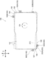
- FIG. 25 shows an example of the outer shape of the frame member 142 viewed from the Z direction (rear side) in a simplified state.
- the illustration of the opening 146A (see FIG. 21) is omitted.
- the shutter unit 140 has a center of gravity GA.
- the center of gravity GA is the point of application of the resultant force of gravity acting on each part of the shutter unit 140.
- the center of gravity GA is a line of action of the thread tension when one point of the shutter unit 140 is hung with the thread and stopped, and the tension of the thread when the other point of the shutter unit 140 is hung with the thread and stopped. Is determined as the intersection with the action line of In the present embodiment, as an example, when the shutter unit 140 is viewed from the Z direction, the center of gravity GA is described as being located on the mounted portion 146C.
- a virtual straight line extending in the Y direction through the center of gravity GA of the shutter unit 140 when viewed from the Z direction in the horizontal posture state of the digital camera 100 is referred to as a first virtual straight line B1.
- a virtual straight line passing through the center of gravity GA and extending in the X direction is referred to as a second virtual straight line B2.
- the virtual straight line passing through the center of gravity GA has a first virtual straight line B1 and a second virtual straight line B2.
- the first virtual straight line B1 and the second virtual straight line B2 are orthogonal to the Z direction (optical axis K (see FIG. 20)) which is the optical axis direction.
- the virtual area SE is an upper left area with respect to the center of gravity GA.
- the virtual area SF is an upper right area with respect to the center of gravity GA.
- the virtual area SG is a lower left area with respect to the center of gravity GA.
- the virtual area SH is a lower right area with respect to the center of gravity GA.
- first corner 182 a portion located in the virtual area SF and including the vertex PA is referred to as a first corner 182.
- second corner 186 a portion that is located in the virtual area SG and that includes the vertex PB is referred to as a second corner 186.
- the first corner 182 and the second corner 186 are an example of a pair of corners that are diagonal in the frame member 142. Further, the first corner portion 182 and the second corner portion 186 face each other in an oblique direction intersecting the X direction and the Y direction in the XY plane.
- the first corner portion 182 has a side surface 183 corresponding to the right side surface of the standing wall portion 164 (see FIG. 21) and a side surface 184 corresponding to the upper side surface of the standing wall portion 166 (see FIG. 21) in the virtual area SF. This is a portion formed by intersecting at the vertex PA. In other words, the side surface 183 and the side surface 184 form the first corner 182.
- the side surface 183 is, for example, along the YZ plane.
- the side surface 184 is, for example, along the XZ plane.
- the second corner 186 has a side 187 corresponding to the left side of the standing wall 158B (see FIG. 21) and a side 188 corresponding to the lower side of the standing wall 158A (see FIG. 21) in the virtual area SG. This is a portion formed by intersecting at the vertex PB. In other words, the side surface 187 and the side surface 188 form the second corner 186.
- the side surface 187 is, for example, along the YZ plane.
- the side surface 188 is, for example, along the XZ plane.
- the spring unit 192 shown in FIG. 22 includes, as an example, a coil spring 194, an inner mounting member 196 provided at one axial end of the coil spring 194, and an outer mounting member 198 provided at the other axial end of the coil spring 194. Having.
- the inner mounting member 196 is a part that is mounted on the shutter unit 140 side.
- the inner attachment member 196 includes, for example, a sheet metal part 196A, a protruding part 196B, and an attachment part 196C.
- the sheet metal part 196A is disposed with the axial direction of the coil spring 194 as the thickness direction.
- the shape when the sheet metal part 196A is viewed from the thickness direction is, for example, a rectangular shape.
- the central portion in the longitudinal direction of the sheet metal part 196A is recessed in a trapezoidal shape toward one side in the thickness direction when viewed from a direction orthogonal to the thickness direction.
- the projecting portion 196B is a portion projecting from the recessed portion of the sheet metal portion 196A in the thickness direction.
- the protrusion 196B is formed, for example, in a columnar shape.
- the outer diameter of the protrusion 196B when viewed from the axial direction is smaller than the inner diameter of the coil spring 194 when viewed from the axial direction.
- the protrusion 196B regulates movement of the coil spring 194 in a direction orthogonal to the axial direction.
- the mounting portion 196C is a portion protruding toward the side opposite to the protruding portion 196B in the recessed portion of the sheet metal portion 196A. Further, the mounting portion 196C is formed so as to be able to engage with the above-described widened portion 117B (see FIG. 18).
- the outer mounting member 198 is a part that is mounted on the camera body 102 side.
- the outer mounting member 198 has, for example, a sheet metal part 198A, a protruding part 198B, and a mounting part 198C.
- the sheet metal part 198A is disposed with the axial direction of the coil spring 194 as the thickness direction.
- the shape when the sheet metal part 198A is viewed from the thickness direction is, for example, a rectangular shape.
- the central portion in the longitudinal direction of the sheet metal part 198A is recessed in a trapezoidal shape toward one side in the thickness direction when viewed from a direction orthogonal to the thickness direction.
- the protruding portion 198B is a portion protruding in the thickness direction from the recessed portion of the sheet metal portion 198A.
- the protruding portion 198B is formed, for example, in a columnar shape.
- the outer diameter of the protrusion 198B when viewed from the axial direction is smaller than the inner diameter of the coil spring 194 when viewed from the axial direction.
- the protrusion 198B regulates movement of the coil spring 194 in a direction orthogonal to the axial direction.
- the mounting portion 198C is a portion protruding toward the side opposite to the protruding portion 198B side in the recessed portion of the sheet metal portion 198A.
- the mounting portion 198C is formed so as to be able to engage with the above-described widened portion 117B (see FIG. 18).
- a coil spring 194 is hooked in a not-shown groove of the sheet metal part 196A.
- the other end of the coil spring 194 is hooked in a not-shown groove of the sheet metal part 198A.
- a coil spring 194, an inner attachment member 196, and an outer attachment member 198 are integrally attached to the camera body 102 and the shutter unit 140.
- the four spring units 192 shown in FIG. 21 are distinguished from the spring units 192A, 192B, 192C, and 192D. When the four spring units 192 are not distinguished, they are simply referred to as spring units 192.
- the spring unit 192A causes the shutter unit 140 to exert a leftward elastic force in the X direction by being sandwiched in the X direction between the upright plate portion 122B and the upright wall portion 164.
- the spring unit 192B causes the shutter unit 140 to exert a downward elastic force in the Y direction by being sandwiched between the upright plate portion 122A and the upright wall portion 166 in the Y direction.
- the ⁇ ⁇ ⁇ ⁇ spring unit 192C causes the shutter unit 140 to exert a rightward elastic force in the X direction on the shutter unit 140 by being sandwiched between the upright plate portion 116B and the upright wall portion 158B in the X direction.
- the spring unit 192D causes the shutter unit 140 to exert an upward elastic force in the Y direction by being sandwiched between the upright plate portion 116A and the upright wall portion 158A in the Y direction.
- FIG. 25 in addition to the frame member 142, four spring units 192 and two rubber members 202 are shown in a simplified manner.
- the four spring units 192 are in contact with the first corner 182 and the second corner 186.
- the spring unit 192A and the spring unit 192B are in contact with the side surfaces 183 and 184 from different directions (X direction or Y direction) when viewed from the Z direction.
- the spring unit 192C and the spring unit 192D are in contact with the side surfaces 187 and 188 from different directions (X direction or Y direction) when viewed from the Z direction.
- the spring unit 192A when viewed from the Z direction, the spring unit 192A is arranged on one side with respect to the virtual straight line B1 and on the upper side in the Y direction.
- the spring unit 192A is arranged in a compressed state, for example, and applies a load Fa [N] to the frame member 142 toward the left side in the X direction.
- a virtual point at which the center axis of the spring unit 192A intersects with the frame member 142 is defined as a point P1.
- the distance in the X direction from the virtual straight line B2 to the point P1 is defined as a distance La [mm].
- the spring unit 192B is disposed on one side with respect to the virtual straight line B1 and on the upper side in the Y direction when viewed from the Z direction.
- the spring unit 192B is arranged, for example, in a compressed state, and applies a load Fb [N] to the frame member 142 downward in the Y direction.
- a virtual point at which the center axis of the spring unit 192B and the frame member 142 intersect is defined as a point P2.
- the distance in the Y direction from the virtual straight line B1 to the point P2 is defined as a distance Lb [mm].
- the spring unit 192C is arranged on the other side of the virtual straight line B1 and below the Y direction when viewed from the Z direction.
- the spring unit 192C is arranged, for example, in a compressed state, and applies a load Fc [N] to the frame member 142 toward the right side in the X direction.
- a virtual point at which the center axis of the spring unit 192C and the frame member 142 intersect is referred to as a point P3.
- the distance in the X direction from the virtual straight line B2 to the point P3 is defined as a distance Lc [mm].
- the spring unit 192D is arranged on the other side of the virtual straight line B1 and below the Y direction when viewed from the Z direction.
- the spring unit 192D is arranged, for example, in a compressed state, and applies a load Fd [N] to the frame member 142 upward in the Y direction.
- a virtual point at which the center axis of the spring unit 192D and the frame member 142 intersect is referred to as a point P4.
- the distance in the Y direction from the virtual straight line B1 to the point P4 is defined as a distance Ld [mm].
- the loads Fa, Fb, Fc, Fd and the distances La, Lb, Lc, Ld are set within a range in which the rotation of the shutter unit 140 around the center of gravity GA within an allowable range is not restricted.
- the rubber member 202 shown in FIG. 21 is made of silicon rubber and formed in a plate shape. Further, two rubber members 202 are used in the digital camera 100 as an example, and absorb the shock acting on the shutter unit 140 when the shutter member 144 moves. The two rubber members 202 are distinguished from the rubber members 202A and 202B. When the two rubber members 202 are not distinguished, they are simply referred to as rubber members 202.
- the rubber member 202A is sandwiched between the upright wall portion 158A and the vertical wall portion 126A in the Y direction.
- the rubber member 202B is sandwiched between the upright wall portion 164 and the upright plate portion 123 in the Y direction. That is, the rubber member 202A and the rubber member 202B are sandwiched between the camera body 102 and the frame member 142.
- the rubber member 202A is disposed in the rotation area S1 of the second corner 186 about the center of gravity GA of the shutter unit 140.
- an imaginary circle RA having a radius of a line segment connecting the center of gravity GA and the vertex PB is drawn.
- the virtual circle RA is a locus of movement of the vertex PB.
- a region surrounded by the virtual circle RA, the first virtual straight line B1, and the second virtual straight line B2 and including the vertex PB is defined as a rotation region S1.
- the arrangement of the rubber member 202A in the rotation area S1 means that not only the entire rubber member 202A is arranged in the rotation area S1, but also that a part of the rubber member 202A is in the rotation area S1. Including being placed.
- the state in which the rubber member 202A is disposed in the rotation area S1 means that the rubber member 202A is in contact with the frame member 142 when the frame member 142 is rotated around the center of gravity GA. In other words, if the frame member 142 and the rubber member 202A do not come into contact with each other when the frame member 142 is rotated, it is not said that the rubber member 202A is arranged in the rotation area S1.
- the rubber member 202B is in contact with the side surface 183 in the virtual area SH.
- the rubber member 202B is merely disposed in an auxiliary manner, and the rubber member 202B is in contact with the side surface 183 in the virtual area SH. May not be arranged.
- the rubber member 202B may be arranged in the rotation area S2 of the first corner 182 about the center of gravity GA. Specifically, a virtual circle RB having a radius of a line connecting the center of gravity GA and the vertex PA is drawn. The virtual circle RB becomes a locus of movement of the vertex PA.
- a region surrounded by the virtual circle RB, the first virtual straight line B1, and the second virtual straight line B2 and including the vertex PA is defined as a rotation region S2.
- the state where the rubber member 202B is arranged in the rotation area S2 means that the rubber member 202B is in a state of contact with the frame member 142 when the frame member 142 is rotated around the center of gravity GA.
- ⁇ Sponge member> Four sponge members 204 are attached to the main body member 124 shown in FIG. 19 with the Z direction as the axial direction.
- the four sponge members 204 are arranged, for example, one each at the upper right, lower right, upper left, and lower left of the main body member 124.
- the sponge member 204 shown in FIG. 24 is a member having a friction coefficient lower than the friction coefficient (static friction coefficient) of the camera body 102 and the friction coefficient (static friction coefficient) of the frame member 142, for example. Further, the sponge member 204 is sandwiched between the camera body 102 and the frame member 142 in the Z direction. Specifically, as an example, the sponge member 204 is fixed to a columnar sponge body 205 having the Z-axis as a central axis direction, and one end surface of the sponge body 205 in the Z direction (a surface on the frame member 142 side). And a rubbing sheet 206.
- the stepped screw 208 shown in FIG. 23A has a shaft 209 and an overhang 212.
- the direction of each part of the stepped screw 208 will be described using the direction in a state where the stepped screw 208 is fastened to the fastened portion 108.
- the -axis portion 209 is arranged with the Z direction as the axial direction.
- the shaft portion 209 includes, for example, a regulated portion 210 and a screw portion 211.
- the regulated portion 210 is formed in a cylindrical shape with the Z direction as the axial direction, and has an outer peripheral surface 210A.
- the length of the regulated portion 210 in the Z direction is set such that the rear end surface of the regulated portion 210 in the Z direction is disposed (projected) behind the rear end surface of the frame member 142 in the Z direction. I have.
- a part of the outer peripheral surface 210A is arranged to face the hole wall 162A of the through hole 162 with a space in the radial direction.
- the screw portion 211 is formed in a column shape having the Z direction as the axial direction.
- the central axis of the screw part 211 is coaxial with the central axis of the regulated part 210.
- the screw portion 211 extends forward from the front end surface of the regulated portion 210 in the Z direction.
- the outer diameter of the screw portion 211 is smaller than the outer diameter of the regulated portion 210.
- On the outer peripheral surface of the screw portion 211 a male screw to be fastened to the female screw of the fastened portion 108 is formed.
- the shaft portion 209 is inserted into the through hole 162 and fastened to the fastened portion 108.
- the overhang portion 212 is a portion that extends from the end of the shaft portion 209 on the frame member 142 side in a direction orthogonal to the Z direction.
- the overhang portion 212 is formed, for example, in a disk shape having a thickness direction in the Z direction.
- the size of the outer diameter of the overhang portion 212 is set to a size such that the overhang portion 212 covers the through hole 162 when viewed from the Z direction.
- a gap is formed between the overhang portion 212 and the frame member 142. The overhang portion 212 restricts the range of movement of the frame member 142 in the Z direction when the frame member 142 comes into contact.
- the spring unit 192 moves in the X direction with respect to the first virtual straight line B1 passing through the center of gravity GA of the shutter unit 140 and orthogonal to the optical axis K. It is arranged on one side and the other side. Then, by supporting the frame member 142 on the camera body 102 (see FIG. 18) via the spring unit 192, the vibration of the shutter unit 140 is suppressed.
- the frame member 142 is supported by contacting the four spring units 192 with the frame member 142, so that the frame member 142 does not have to be rigidly connected to the camera body 102. Since the frame member 142 is not rigidly connected to the camera main body 102, transmission of an impact force from the shutter unit 140 to the camera main body 102 can be suppressed as compared with a configuration in which the frame member 142 is rigidly connected. In other words, in the digital camera 100, the movement of the frame member 142 is allowed within the allowable range by the four spring units 192, so that the transmission of the impact force from the shutter unit 140 to the camera body 102 is suppressed. can do.
- the shutter button 18 (see FIG. 20) is operated, in the shutter unit 140, the shutter member 144 (the front curtain member 43 and the rear curtain member 46) moves upward after moving downward in the Y direction.
- an impact force acts on the frame member 142, so that the frame member 142 may be rotated about the center of gravity GA (see FIG. 26).
- the impact force acting on the frame member 142 is reduced by the loads (restoring forces) of the four spring units 192. That is, transmission of the impact force from the shutter unit 140 to the camera body 102 can be suppressed.
- the spring units 192 are arranged on one side and the other side in the X direction with respect to the virtual straight line B1 passing through the center of gravity GA. Since the spring unit 192 is arranged on one side and the other side with respect to the virtual straight line B1, the rotation of the shutter unit 140 (frame member 142) about the center of gravity GA is prevented from being biased in one direction. Is done. Since the biased rotation of the shutter unit 140 is suppressed, the contact between the shutter unit 140 and the camera body 102 is suppressed, so that the transmission of the impact force from the shutter unit 140 to the camera body 102 can be suppressed.
- the transmission of the impact force from the shutter unit 140 to the camera body 102 is suppressed, so that the impact force transmitted to the correction unit 50 (see FIG. 20) is reduced.
- the erroneous correction in 50 can be suppressed.
- the first and second corners 182 and 186 of the frame member 142 which are diagonal, are in contact with the four spring units 192.
- the other diagonal corners of the frame member 142 are not in contact with the spring unit 192. That is, the frame member 142 is easily rotated around the center of gravity GA.
- the illustration of the opening 146A (see FIG. 21) is omitted.
- the one-way rotation about the center of gravity GA of the frame member 142 caused by the impact force caused by the downward movement of the shutter member 144 (see FIG. 21) in the Y direction causes the frame member 142 to be diagonally opposed to the frame member 142. Is limited by contact with one of the spring units 192. Furthermore, rotation in the other direction (reverse direction) about the center of gravity GA of the frame member 142 caused by an impact force caused by the upward movement of the shutter member 144 in the Y direction causes the frame member 142 and the other diagonally opposite rotation. It is limited by contact with the spring unit 192. That is, the vibration of the frame member 142 is attenuated by the one diagonal spring unit 192 and the other diagonal spring unit 192. Therefore, transmission of an impact force from the shutter unit 140 to the camera body 102 (see FIG. 21) can be suppressed.
- the fact that the shutter unit 140 is easily rotated about the center of gravity GA means that, in other words, when the mass of the shutter unit 140 is large, it is not necessary to forcibly move the shutter unit 140 in parallel. I have. That is, when the impact force acting on the shutter unit 140 is attenuated by the load (restoring force) of the spring unit 192 while moving the shutter unit 140, the amount of movement of the shutter unit 140 is ensured, so that the impact force is attenuated. Can be made easier.
- the two spring units 192 contact the side surfaces 183 and 184 from different directions, and the other two spring units 192 contact the side surfaces 187 and 188 from different directions. .
- the spring unit 192 not only rotation of the shutter unit 140 in one direction but also rotation in the opposite direction is suppressed by the spring unit 192, so that vibration of the shutter unit 140 can be suppressed.
- the rubber member 202 is disposed in the rotation area S1 of the second corner 186 about the center of gravity GA, and is sandwiched between the camera body 102 (see FIG. 21) and the frame member 142. I have.
- the impact impact force
- the load restoring force
- the sponge member 204 is sandwiched between the camera body 102 and the frame member 142 in the Z direction.
- a frictional force equal to or less than the frictional force Ft acts on the frame member 142.
- the vibration of the frame member 142 is attenuated. That is, since the vibration of the shutter unit 140 is attenuated by the frictional forces of the four sponge members 204, the transmission of the impact force from the shutter unit 140 to the camera body 102 is suppressed. Since the transmission of the impact force from the shutter unit 140 to the camera body 102 is suppressed, the impact force transmitted to the correction unit 50 (see FIG. 20) is reduced, so that erroneous correction in the correction unit 50 can be suppressed. it can.
- the frame member 142 is arranged with a gap in the Z direction with respect to the camera body 102 so as to be rotatable.
- the sponge member 204 supports the frame member 142 from the front side in the Z direction. Tilt to one side (front side) can be suppressed.
- FIG. 27 illustrates a digital camera 220 as an example of the imaging device according to the sixth embodiment.
- the digital camera 220 has a configuration in which a covering member 222 as an example of a contact member is added to the digital camera 100 of the fifth embodiment (see FIG. 18).
- the covering member 222 is made of, for example, silicon rubber, and is formed in a cylindrical shape. Further, the covering member 222 covers the outer peripheral surface 210A. In other words, the covering member 222 is provided at a portion of the outer peripheral surface 210A of the shaft portion 209 facing the hole wall 162A of the through hole 162. Further, the covering member 222 has elasticity and is arranged so as to be able to contact the hole wall 162A.
- the frame member 32 when viewed from the Z direction, the frame member 32 may have a curved shape instead of a polygonal shape. Further, the frame member 32 may be arranged in the Z direction with the camera body 12 without being accommodated in the camera body 12. Note that the above configuration is the same for the digital cameras 70, 80, and 90.
- the plurality of rubber members 84 may be in contact with only one of the side surface 35A and the side surface 35B forming the corner 35.
- the surface with which the sponge member 92 contacts is not limited to the surface of the frame member 32 on the imaging element 20 side, but may be the surface of the frame member 32 on the subject side or the outer peripheral surface of the frame member 32.
- the elastic member is not limited to the metal coil spring 60 but may be a rubber or resin member having elasticity.
- the elastic member is not limited to a member that applies a load to the shutter unit 30 (the frame member 32) in the pressing direction, and may be a member that applies a tensile force to the shutter unit 30.
- a tension spring may be arranged above the shutter unit 30 in the Y direction to suspend the shutter unit 30 (frame member 32) in the Y direction.
- the number of coil springs 60 is not limited to six or ten, and may be any number of two or more.
- the damping member is not limited to the rubber member 84, but may be a resin member or a viscous member. Further, the damping member may be formed of a gel-like member.
- the rubber member 84 is not limited to silicon rubber, but may be other rubber such as urethane rubber.
- the number of the rubber members 84 is not limited to eight, and may be any number of two or more.
- the friction member may be composed of only the sponge body 94 without the rubbing sheet 96. Further, the friction member may be formed of another member such as urethane and / or rubber.
- the number of sponge members 92 is not limited to four, and may be one or two or more.
- the first virtual straight line A1 and the second virtual straight line A2 are not limited to straight lines along the X and Y directions, but may be straight lines extending in oblique directions intersecting the X and Y directions.
- the plurality of spring units 192 may be in contact with only one of the two side surfaces forming the corner when viewed from the Z direction.
- the rubber member 202 may be in contact with the frame member 142 outside the rotation area S1 of the second corner 186. Further, the rubber member 202 is not limited to a member that is in contact with the frame member 142 before the rotation of the frame member 142. That is, the rubber member 202 may be a member that is brought into non-contact with the frame member 142 before the rotation of the frame member 142 and that comes into contact with the frame member 142 when the frame member 142 rotates.
- the sponge member 204 may not be sandwiched between the camera body 102 and the frame member 142.
- a member that restricts the rotation range of the frame member 142 (restricts movement) by contacting the outer edge of the frame member 142 may be provided.
- the spring unit 192 may be constituted only by the coil spring 194.
- the part where the spring unit 192 is brought into contact is not limited to the first corner 182 and the second corner 186 of the frame member 142, but may be another set of corners that are diagonal.
- the elastic member is not limited to the metal spring unit 192 (coil spring 194), but may be a member made of rubber or resin and having elasticity.
- the elastic member is not limited to a member that applies a load to the shutter unit 140 (the frame member 142) in the pressing direction, and may be a member that applies a tensile force to the shutter unit 140.
- a tension spring may be arranged above the shutter unit 140 in the Y direction to suspend the shutter unit 140 (frame member 142) in the Y direction.
- the number of the spring units 192 may be two or more for each side surface.
- the shock absorbing member is not limited to the rubber member 202, and may be a resin member or a viscous member. Further, the shock absorbing member may be formed of a gel-like member.
- the rubber member 202 is not limited to silicon rubber, but may be other rubber such as urethane rubber.
- the number of the rubber members 202 arranged at the diagonal corners is not limited to one, and may be plural.
- the sponge member 204 may be constituted by only the sponge body 205 without the rubbing sheet 206. Further, the sponge member 204 may be formed of another member such as urethane and / or rubber. The number of sponge members 204 is not limited to four, and may be one or two or more.
- the fastened portion 108 may be attached to the camera main body 102 by using a cylindrical pin instead of the stepped screw 208 and press-fitting the pin into the cylindrical portion, as the cylindrical portion having the Z direction as the axial direction. Then, the movement of the frame member 142 may be restricted by the pin.
- a and / or B has the same meaning as “at least one of A and B”. That is, “A and / or B” means that only A may be used, only B may be used, or a combination of A and B may be used. Also, in the present specification, the same concept as “A and / or B” is applied to a case where three or more matters are expressed by being connected by “and / or”.
Landscapes
- Engineering & Computer Science (AREA)
- Multimedia (AREA)
- Signal Processing (AREA)
- Physics & Mathematics (AREA)
- General Physics & Mathematics (AREA)
- Studio Devices (AREA)
- Adjustment Of Camera Lenses (AREA)
- Shutters For Cameras (AREA)
Abstract
撮像装置は、装置本体に設けられ、光学像を結像させる光の光軸と直交する撮像面を備えた撮像素子と、装置本体に設けられ、支持部材と支持部材に支持され且つ光軸と直交する方向に移動するシャッタ部材とを備え、撮像素子に入射される光の量を調整するシャッタユニットと、装置本体に設けられ、撮像素子を光軸と直交する方向に移動させることで、手振れ量を補正する手振れ補正部と、光軸の光軸方向から見た場合に、シャッタユニットの重心を通り光軸と直交する仮想直線に対して少なくとも一方側と他方側とに配置され、且つ装置本体と支持部材とに接触する複数の弾性部材と、を有する。
Description
本開示は、撮像装置及び撮像装置の振動抑制方法に関する。
特開2011-107439号公報のぶれ補正カメラは、撮影光学系と、撮像素子と、ぶれ補正手段と、撮影制御部と、シャッタボタン及びシャッタバネを含む撮像本体部と、撮像本体部を回動支持するフレームと、フレームに保持され撮像本体部を支持する支持バネと、を備える。
シャッタ部材が移動されるシャッタユニットと、撮像素子が移動される手振れ補正部とを有する撮像装置がある。撮像装置では、シャッタ部材が移動された場合の衝撃力が手振れ補正部に伝わることで、撮像素子における解像度の低下などの誤補正が生じる可能性がある。特に、特開2011-107439号公報の構成と同様の構成では、撮像本体部における回動軸側が支持バネで支持されていないので、シャッタ部材が移動された場合の衝撃力が回動軸側を介して手振れ補正部にそのまま伝わり、手振れ補正部において誤補正が生じる可能性がある。
つまり、シャッタ部材が移動されるシャッタユニットと、撮像素子が移動される手振れ補正部とを有する構成において、シャッタ部材が移動された場合に、手振れ補正部において誤補正が生じるのを抑制するには、改善の余地がある。
本開示の技術は、シャッタ部材が移動するシャッタユニットと、撮像素子が移動される手振れ補正部とを有する構成において、シャッタ部材が移動した場合に、手振れ補正部において誤補正が生じるのを抑制することができる撮像装置及び撮像装置の振動抑制方法を提供する。
本開示の技術に係る第1の態様は、装置本体に設けられ、光学像を結像させる光の光軸と直交する撮像面を備えた撮像素子と、装置本体に設けられ、支持部材と支持部材に支持され且つ光軸と直交する方向に移動するシャッタ部材とを備え、撮像素子に入射される光の量を調整するシャッタユニットと、装置本体に設けられ、撮像素子を光軸と直交する方向に移動させることで、手振れ量を補正する手振れ補正部と、光軸の光軸方向から見た場合に、シャッタユニットの重心を通り光軸と直交する仮想直線に対して少なくとも一方側と他方側とに配置され、且つ装置本体と支持部材とに接触する複数の弾性部材と、を有する撮像装置である。
本開示の技術に係る第2の態様は、複数の弾性部材のうち2つの弾性部材は、仮想直線上に間隔をあけて配置されている、第1の態様に係る撮像装置である。
本開示の技術に係る第3の態様は、複数の弾性部材は、シャッタ部材の移動方向に支持部材と並んでいる、第1の態様又は第2の態様に係る撮像装置である。
本開示の技術に係る第4の態様は、複数の弾性部材が支持部材に作用させる荷重は、仮想直線からの距離が長い方が短い方に比べて小さい、第1の態様から第3の態様の何れか1つの態様に係る撮像装置である。
本開示の技術に係る第5の態様は、シャッタ部材の移動方向に沿って延び、複数の弾性部材は、一方側で移動方向に間隔をあけて配置された複数の第1弾性部材と、他方側で移動方向に間隔をあけて配置された複数の第2弾性部材とを有し、光軸方向から見た場合に、移動方向と直交する直交方向における仮想直線から第1弾性部材までの距離をL1とし、第1弾性部材が支持部材に対して移動方向に作用させる荷重をF1とし、直交方向における仮想直線から第2弾性部材までの距離をL2とし、第2弾性部材が支持部材に対して移動方向に作用させる荷重をF2として、F1×L1=F2×L2である、第1の態様から第4の態様の何れか1つの態様に係る撮像装置である。
本開示の技術に係る第6の態様は、仮想直線は、光軸方向から見た場合に、移動方向に延びる第1仮想直線と、直交方向に延びる第2仮想直線とを有し、第2仮想直線に対する移動方向の一方側に配置された第3弾性部材と、第2仮想直線に対する移動方向の他方側に配置された第4弾性部材と、を有し、装置本体と支持部材とに接触する複数の補助弾性部材が設けられ、移動方向における第2仮想直線から第3弾性部材までの距離をLAとし、第3弾性部材が支持部材に対して直交方向に作用させる荷重をFAとし、移動方向における第2仮想直線から第4弾性部材までの距離をLBとし、第4弾性部材が支持部材に対して直交方向に作用させる荷重をFBとして、FA×LA=FB×LBである、第5の態様に係る撮像装置である。
本開示の技術に係る第7の態様は、シャッタユニットの振動を減衰させる複数の減衰部材が、装置本体と支持部材とで挟まれている、第1の態様から第6の態様の何れか1つの態様に係る撮像装置である。
本開示の技術に係る第8の態様は、支持部材は、光軸方向から見た場合に、多角形状に形成されている、第7の態様に係る撮像装置である。
本開示の技術に係る第9の態様は、複数の減衰部材は、光軸方向から見た場合に、支持部材の角部を形成する2つの側面に互いに異なる方向から接触している、第8の態様に係る撮像装置である。
本開示の技術に係る第10の態様は、複数の減衰部材は、支持部材の振動を摩擦力によって減衰させる摩擦部材を有する、第7の態様から第9の態様の何れか1つの態様に係る撮像装置である。
本開示の技術に係る第11の態様は、支持部材は、装置本体に収容されている、第1の態様から第10の態様の何れか1つの態様に係る撮像装置である。
本開示の技術に係る第12の態様は、複数の弾性部材は、光軸方向から見た場合に、支持部材における対角となる1組の角部と接触している、第1の態様に係る撮像装置である。
本開示の技術に係る第13の態様は、複数の弾性部材は、光軸方向から見た場合に、角部を形成する2つの側面に互いに異なる方向から接触している、第12の態様に係る撮像装置である。
本開示の技術に係る第14の態様は、シャッタユニットに作用する衝撃を吸収する衝撃吸収部材が、シャッタユニットの重心を中心とする角部の回転領域内に配置され、且つ装置本体と支持部材とで挟まれている、第12の態様又は第13の態様に係る撮像装置である。
本開示の技術に係る第15の態様は、摺動部材が、光軸方向において、装置本体と支持部材とで挟まれている、第12の態様から第14の態様の何れか1つの態様に係る撮像装置である。
本開示の技術に係る第16の態様は、支持部材には、支持部材を光軸方向に貫通する貫通孔が形成され、装置本体には、被締結部が形成され、貫通孔に挿入され且つ被締結部に締結される軸部と、軸部の支持部材側の端部から軸方向と交差する方向に張り出された張出部とを有する締結部材が設けられた、第12の態様から第15の態様の何れか1つの態様に係る撮像装置である。
本開示の技術に係る第17の態様は、軸部の外周面における貫通孔の孔壁と対向する部位には、弾性を有し孔壁と接触可能な接触部材が設けられている、第16の態様に係る撮像装置である。
本開示の技術に係る第18の態様は、光学像を結像させる光の光軸と直交する撮像面を備えた撮像素子と、装置本体に設けられ、支持部材と支持部材に支持され且つ光軸と直交する方向に移動するシャッタ部材とを備え、撮像素子に入射される光の量を調整するシャッタユニットと、撮像素子を光軸と直交する方向に移動させることで、手振れ量を補正する手振れ補正部と、を有する撮像装置の振動抑制方法であって、光軸の光軸方向から見た場合に、シャッタユニットの重心を通り光軸と直交する仮想直線に対して少なくとも一方側と他方側とに弾性部材を配置し、支持部材を、弾性部材を介して装置本体に支持させることで、シャッタユニットの振動を抑制させる撮像装置の振動抑制方法である。
本開示の技術によれば、シャッタ部材が移動するシャッタユニットと、撮像素子が移動される手振れ補正部とを有する構成において、シャッタ部材が移動した場合に、手振れ補正部において誤補正が生じるのを抑制することができる。
以下、本開示の技術に係る撮像装置及び撮像装置の振動抑制方法の一例について説明する。
[第1実施形態]
図1には、第1実施形態に係る撮像装置の一例としてのデジタルカメラ10が示されている。デジタルカメラ10は、カメラ本体12と、撮影レンズ部17(図2参照)と、撮像素子20(図2参照)と、シャッタユニット30と、補正ユニット50(図2参照)と、複数の弾性部材の一例としての6つのコイルバネ60とを有する。
図1には、第1実施形態に係る撮像装置の一例としてのデジタルカメラ10が示されている。デジタルカメラ10は、カメラ本体12と、撮影レンズ部17(図2参照)と、撮像素子20(図2参照)と、シャッタユニット30と、補正ユニット50(図2参照)と、複数の弾性部材の一例としての6つのコイルバネ60とを有する。
<カメラ本体>
カメラ本体12は、装置本体の一例である。また、カメラ本体12は、中空の箱状に形成されたカバー部材14と、カバー部材14の内側に設けられたベース部材16とを含んで構成されている。カメラ本体12には、図示しない液晶モニタ、複数のボタン及びダイヤルが設けられている。カメラ本体12の主要部の外形は、図示しない被写体からの光の光軸方向から見た場合に、矩形状に形成されている。カメラ本体12の一部は、山型に突出されている。
カメラ本体12は、装置本体の一例である。また、カメラ本体12は、中空の箱状に形成されたカバー部材14と、カバー部材14の内側に設けられたベース部材16とを含んで構成されている。カメラ本体12には、図示しない液晶モニタ、複数のボタン及びダイヤルが設けられている。カメラ本体12の主要部の外形は、図示しない被写体からの光の光軸方向から見た場合に、矩形状に形成されている。カメラ本体12の一部は、山型に突出されている。
以後の説明では、カメラ本体12の長手方向をX方向と称し、カメラ本体12の短手方向をY方向と称する。さらに、光の光軸方向をZ方向と称する。X方向、Y方向及びZ方向は、互いに直交する。また、カメラ本体12について、X方向が水平方向に沿った配置状態を、デジタルカメラ10の横姿勢状態と称する。カメラ本体12について、X方向が水平方向と直交する鉛直方向に沿った配置状態を、デジタルカメラ10の縦姿勢状態と称する。
カバー部材14は、一例として、図示しない分割線を境にして、Z方向に2つに分割される。具体的には、カバー部材14は、Z方向における図示しない被写体側の前カバー部材14Aと、Z方向における撮像素子20側の後カバー部材14B(図2参照)とを有する。
ベース部材16は、一例として、Z方向を厚さ方向とする板金で構成されている。また、ベース部材16は、前カバー部材14Aの裏面に重ねられた状態で、複数のビス19を用いて、前カバー部材14Aに締結されている。ベース部材16の一部には、ベース部材16をZ方向に貫通した図示しない貫通孔が形成されている。貫通孔の大きさは、被写体からの光の入射に影響しない大きさとされている。
ベース部材16のZ方向における撮像素子20(図2参照)側の裏面16Aには、一例として、撮像素子20側に向けて突出された6つの立板部15が立設されている。6つの立板部15は、Z方向から見た場合に、ベース部材16に対するY方向の上側と下側とに、X方向に間隔をあけて配置されている。また、6つの立板部15は、Y方向を厚さ方向として配置されている。6つの立板部15の外形は、Y方向から見た場合に四角形状とされている。
図2には、デジタルカメラ10の内部をZ方向における被写体側から見た状態が模式的に示されている。カメラ本体12のX方向中央に対する一方側で且つY方向中央に対する上側の部位には、シャッタボタン18が設けられている。また、カメラ本体12の内部には、後述する撮像素子20と、デジタルカメラ10の各部の動作を制御する制御部24と、加速度センサ26と、角速度センサ28と、補正ユニット50とが設けられている。制御部24は、コンピュータの一例であり、図示しないCPU(Central Processing Unit)、記憶部及び回路基板を含んで構成されている。
加速度センサ26では、シャッタボタン18が押された場合において、デジタルカメラ10のX-Y面内での並進運動の加速度が検出される。角速度センサ28では、シャッタボタン18が押された場合において、デジタルカメラ10の回転運動の角速度が検出される。加速度及び角速度の情報は、制御部24に送られる。
<撮影レンズ部>
図2に示す撮影レンズ部17は、カメラ本体12に一体的に組付けられている。また、撮影レンズ部17は、図示しないレンズを含んで構成されており、後述する撮像素子20に光学像ZAを結像させる。なお、光学像ZAは、一例として、人型で示されている。
図2に示す撮影レンズ部17は、カメラ本体12に一体的に組付けられている。また、撮影レンズ部17は、図示しないレンズを含んで構成されており、後述する撮像素子20に光学像ZAを結像させる。なお、光学像ZAは、一例として、人型で示されている。
<撮像素子>
撮像素子20は、一例として、CCD(Charge Coupled Device)イメージセンサを用いて構成されている。なお、撮像素子20は、CCDイメージセンサに限らず、例えば、CMOS(Complementary Metal-Oxide-Semiconductor)イメージセンサなどの他のイメージセンサで構成されていてもよい。また、撮像素子20は、入射された光が光学像ZAを結像する結像面21を備えている。結像面21は、撮像面の一例である。また、結像面21は、Z方向から見た場合に、一例として、X方向を長手方向としY方向を短手方向とする長方形状に形成されている。
撮像素子20は、一例として、CCD(Charge Coupled Device)イメージセンサを用いて構成されている。なお、撮像素子20は、CCDイメージセンサに限らず、例えば、CMOS(Complementary Metal-Oxide-Semiconductor)イメージセンサなどの他のイメージセンサで構成されていてもよい。また、撮像素子20は、入射された光が光学像ZAを結像する結像面21を備えている。結像面21は、撮像面の一例である。また、結像面21は、Z方向から見た場合に、一例として、X方向を長手方向としY方向を短手方向とする長方形状に形成されている。
さらに、撮像素子20は、結像面21がX-Y面に沿った配置状態で、後述する補正ユニット50に支持されている。換言すると、撮像素子20は、カメラ本体12に設けられている。また、撮像素子20の結像面21は、光学像ZAを結像させる光の光軸Kと直交(直交配置)されている。
<シャッタユニット>
図3に示すシャッタユニット30は、カメラ本体12(図1参照)に設けられている。具体的には、シャッタユニット30は、フォーカルプレーンシャッタとして構成されている。また、シャッタユニット30は、Z方向において、撮影レンズ部17(図2参照)と、撮像素子20(図2参照)との間に配置されており、撮像素子20に入射される光の量を調整する機能を有する。さらに、シャッタユニット30は、支持部材の一例としてのフレーム部材32と、シャッタ部材42とを有する。
図3に示すシャッタユニット30は、カメラ本体12(図1参照)に設けられている。具体的には、シャッタユニット30は、フォーカルプレーンシャッタとして構成されている。また、シャッタユニット30は、Z方向において、撮影レンズ部17(図2参照)と、撮像素子20(図2参照)との間に配置されており、撮像素子20に入射される光の量を調整する機能を有する。さらに、シャッタユニット30は、支持部材の一例としてのフレーム部材32と、シャッタ部材42とを有する。
<フレーム部材>
図1に示すフレーム部材32は、一例として、フレーム部材32の主要部を構成する本体部34と、本体部34に固定されたブラケット部38とを有する。また、フレーム部材32は、一例として、カメラ本体12に収容されている。
図1に示すフレーム部材32は、一例として、フレーム部材32の主要部を構成する本体部34と、本体部34に固定されたブラケット部38とを有する。また、フレーム部材32は、一例として、カメラ本体12に収容されている。
図3に示す本体部34は、Z方向を厚さ方向とする箱状に形成されている。換言すると、本体部34は、X-Y面に沿って広がっている。また、本体部34は、一例として、Z方向から見た場合に、3箇所の直角の角部36を含む複数の角部35を有する多角形状に形成されている。さらに、本体部34は、一例として、Z方向から見た場合に、本体部34をZ方向に貫通した開口部34Aと、開口部34Aを囲む周縁部34Bと、後述する駆動部48が取付けられる被取付部34Cとを有する。周縁部34Bには、後述する先幕部材43及び後幕部材46をY方向に案内する図示しない案内部が形成されている。なお、図3では、カメラ本体12及びブラケット部38(図1参照)の図示を省略している。
図4に示すブラケット部38は、一例として、X-Y面に沿った平板状の固定部38Aと、固定部38Aの周縁でZ方向に立上げられた複数の立壁部38Bとを有する。固定部38Aは、Z方向における被写体側から本体部34に重ねられた状態で、図示しないビスを用いて、本体部34に固定されている。また、固定部38Aには、Z方向に貫通された4つの貫通孔39(図1参照)が形成されている。貫通孔39は、一例として、Z方向から見た場合に四角形状に形成されている。
図1に示すブラケット部38は、Z方向から見た場合に、本体部34よりもX方向及びY方向の外側に延びている。複数の立壁部38Bは、X方向又はY方向を厚さ方向として、Z方向に延びる板状の壁部である。また、複数の立壁部38Bの一部は、6つの立板部15とY方向に対向配置されている。
図5に示す貫通孔39には、ネジ部材41の軸部41Bが、Z方向に挿入されている。ネジ部材41は、一例として、円板状の頭部41Aと、頭部41Aの中心から一方向に延びる円柱状の軸部41Bと、軸部41Bの先端側に形成された雄ネジ部41Cとを有する。なお、各図では、頭部41Aを回転させるための十字溝の図示を省略している。頭部41Aの大きさは、貫通孔39の周縁部とZ方向に接触可能な大きさとされている。軸部41Bの太さは、貫通孔39にZ方向に通された状態において、貫通孔39の周縁部とX方向及びY方向(図1参照)に隙間があく程度の太さとされている。雄ネジ部41Cは、ベース部材16に形成された雌ネジ部47に締結される。
ネジ部材41は、シャッタユニット30がベース部材16(カメラ本体12)に対してZ方向に過度に位置ずれすることを規制している。一方、ネジ部材41は、貫通孔39が形成された部位において、シャッタユニット30がカメラ本体12に対してX方向及びY方向に移動可能となる自由度を与えている。さらに、ネジ部材41は、シャッタユニット30がX方向及びY方向に必要以上に移動された場合には、貫通孔39の周縁部と接触することで、シャッタユニット30の過度の移動を規制する機能を有している。
<シャッタ部材>
図3に示すシャッタ部材42は、フレーム部材32に支持されている。また、シャッタ部材42は、一例として、先幕部材43、リンク部材44A、連結ピン45A、後幕部材46、リンク部材44B及び連結ピン45Bを含んで構成されている。なお、本実施形態では、先幕部材43及び後幕部材46を駆動する駆動部48を、シャッタ部材42に含める。
図3に示すシャッタ部材42は、フレーム部材32に支持されている。また、シャッタ部材42は、一例として、先幕部材43、リンク部材44A、連結ピン45A、後幕部材46、リンク部材44B及び連結ピン45Bを含んで構成されている。なお、本実施形態では、先幕部材43及び後幕部材46を駆動する駆動部48を、シャッタ部材42に含める。
先幕部材43は、X方向の長さが開口部34AのX方向の長さ以上とされた幕材で構成され、Z方向を厚さ方向として配置されている。先幕部材43のX方向の一端部には、リンク部材44Aの長手方向の一端部が、Z方向を軸方向とする連結ピン45Aによって連結されている。リンク部材44Aの長手方向の他端部は、他の連結ピン45Aによって、被取付部34Cに連結されている。
後幕部材46は、X方向の長さが開口部34AのX方向の長さ以上とされた幕材で構成され、Z方向を厚さ方向として配置されている。後幕部材46のX方向の一端部には、リンク部材44Bの長手方向の一端部が、Z方向を軸方向とする連結ピン45Bによって連結されている。リンク部材44Bの長手方向の他端部は、他の連結ピン45Bによって、被取付部34Cに連結されている。後幕部材46は、先幕部材43に対してY方向の上側に配置されている。先幕部材43及び後幕部材46は、既述の案内部に案内されることで、Y方向に移動可能とされている。Y方向は、光軸Kと直交する方向で且つシャッタ部材42が移動する移動方向の一例である。X方向は、移動方向と直交する直交方向の一例である。
駆動部48は、図示しない電源部からの通電により回転駆動されるモータ48Aと、モータ48Aの回転駆動をリンク部材44A及びリンク部材44Bに伝達させる、図示しない複数のギヤから成る駆動伝達部48Bとで構成されている。駆動部48は、一例として、シャッタボタン18(図2参照)が押された場合に、先幕部材43及び後幕部材46をY方向の上側に移動させた後で、先幕部材43をY方向下側に移動させ、続いて、後幕部材46をY方向下側に移動させる構成とされている。シャッタユニット30では、Y方向に移動される先幕部材43と後幕部材46とのY方向のスリット間隔を変えることで、デジタルカメラ10(図1参照)の露光時間が調整される。
<シャッタユニットの重心>
図6に示すシャッタユニット30は、重心Gを有する。重心Gとは、シャッタユニット30の各部分にはたらく重力の合力の作用点である。重心Gは、一例として、シャッタユニット30の1点を糸で吊るして静止した場合の糸の張力の作用線と、シャッタユニット30の他の1点を糸で吊るして静止した場合の糸の張力の作用線との交点として求められる。なお、本実施形態では、一例として、シャッタユニット30をZ方向から見た場合に、重心Gが被取付部34C上に位置しているとして説明する。重心Gを通りY方向に沿って延びる線を仮想直線A1と称する。仮想直線A1は、光軸方向であるZ方向と直交する。また、仮想直線A1は、X方向から見た場合に、光軸Kと直交する。
図6に示すシャッタユニット30は、重心Gを有する。重心Gとは、シャッタユニット30の各部分にはたらく重力の合力の作用点である。重心Gは、一例として、シャッタユニット30の1点を糸で吊るして静止した場合の糸の張力の作用線と、シャッタユニット30の他の1点を糸で吊るして静止した場合の糸の張力の作用線との交点として求められる。なお、本実施形態では、一例として、シャッタユニット30をZ方向から見た場合に、重心Gが被取付部34C上に位置しているとして説明する。重心Gを通りY方向に沿って延びる線を仮想直線A1と称する。仮想直線A1は、光軸方向であるZ方向と直交する。また、仮想直線A1は、X方向から見た場合に、光軸Kと直交する。
<補正ユニット>
図2に示す補正ユニット50は、手振れ補正部の一例であり、カメラ本体12に設けられている。また、補正ユニット50は、一例として、撮像素子20をX方向及びY方向に移動させることで、デジタルカメラ10の手振れ量を補正する。具体的には、補正ユニット50は、ベースプレート52と、Y方向スライダ54と、Y方向アクチュエータ56と、X方向スライダ58と、X方向アクチュエータ62とを有する。
図2に示す補正ユニット50は、手振れ補正部の一例であり、カメラ本体12に設けられている。また、補正ユニット50は、一例として、撮像素子20をX方向及びY方向に移動させることで、デジタルカメラ10の手振れ量を補正する。具体的には、補正ユニット50は、ベースプレート52と、Y方向スライダ54と、Y方向アクチュエータ56と、X方向スライダ58と、X方向アクチュエータ62とを有する。
ベースプレート52は、Z方向を厚さ方向とする板状に形成されている。また、ベースプレート52には、撮像素子20が固定されている。Y方向スライダ54は、ベースプレート52をY方向に移動可能に支持している。Y方向アクチュエータ56は、ベースプレート52をY方向に移動させる。X方向スライダ58は、ベースプレート52、Y方向スライダ54及びY方向アクチュエータ56をX方向に移動可能に支持している。X方向アクチュエータ62は、X方向スライダ58をX方向に移動させる。
制御部24は、一例として、角速度センサ28で手振れが検出された場合に、手振れを打消す方向にX方向アクチュエータ62及びY方向アクチュエータ56を駆動させ、撮像素子20をX方向及びY方向に移動させる。撮像素子20が移動されることで、撮像素子20の結像面21における光学像ZAのずれ(手振れ量に相当する)が補正される。なお、加速度センサ26及び角速度センサ28の検出結果に基づいて、手振れを補正してもよい。
<コイルバネ>
図6に示す6つのコイルバネ60を、コイルバネ60A、60B、60C、60D、60E、60Fと区別する。コイルバネ60A、60B、60C、60D、60E、60Fは、カメラ本体12(図1参照)とフレーム部材32とにY方向を軸方向(伸縮方向)として接触しており、フレーム部材32に向けて荷重(復元力)を作用させている。
図6に示す6つのコイルバネ60を、コイルバネ60A、60B、60C、60D、60E、60Fと区別する。コイルバネ60A、60B、60C、60D、60E、60Fは、カメラ本体12(図1参照)とフレーム部材32とにY方向を軸方向(伸縮方向)として接触しており、フレーム部材32に向けて荷重(復元力)を作用させている。
コイルバネ60Aは、Z方向から見た場合に、仮想直線A1に対する一方側(開口部34Aが配置された側)で且つY方向の下側に配置されている。コイルバネ60Aの軸方向一端部は、立壁部38B(図1参照)と接触している。なお、図6では、立壁部38Bの図示を省略している。コイルバネ60Aの軸方向他端部は、立板部15と接触している。コイルバネ60Aは、例えば圧縮状態で配置されており、フレーム部材32に対して、Y方向の上側に向けて、荷重F1〔N〕(図7参照)を作用させている。コイルバネ60Aの中心軸と立壁部38Bとが交わる仮想の点を点Aとする。仮想直線A1から点AまでのX方向の距離を距離L1〔mm〕(図7参照)とする。
コイルバネ60Bは、Z方向から見た場合に、仮想直線A1に対する他方側(モータ48Aが配置された側)で且つY方向の下側に配置されている。コイルバネ60Bの軸方向一端部は、立壁部38B(図1参照)と接触している。コイルバネ60Bの軸方向他端部は、立板部15と接触している。コイルバネ60Bは、例えば圧縮状態で配置されており、フレーム部材32に対して、Y方向の上側に向けて、荷重F2〔N〕(図7参照)を作用させている。コイルバネ60Bの中心軸と立壁部38Bとが交わる仮想の点を点Bとする。仮想直線A1から点BまでのX方向の距離を距離L2〔mm〕(図7参照)とする。
コイルバネ60Cは、Z方向から見た場合に、仮想直線A1に対する一方側で且つY方向の上側に配置されている。つまり、コイルバネ60Cは、コイルバネ60Aに対してY方向に間隔をあけて配置されている。コイルバネ60Cの軸方向一端部は、立壁部38B(図1参照)と接触している。コイルバネ60Cの軸方向他端部は、立板部15と接触している。コイルバネ60Cは、例えば圧縮状態で配置されており、フレーム部材32に対して、Y方向の下側に向けて、荷重F3〔N〕(図7参照)を作用させている。コイルバネ60Cの中心軸と立壁部38Bとが交わる仮想の点を点Cとする。仮想直線A1から点CまでのX方向の距離を距離L3〔mm〕(図7参照)とする。
コイルバネ60Dは、Z方向から見た場合に、仮想直線A1に対する他方側で且つY方向の上側に配置されている。つまり、コイルバネ60Dは、コイルバネ60Bに対してY方向に間隔をあけて配置されている。コイルバネ60Dの軸方向一端部は、立壁部38B(図1参照)と接触している。コイルバネ60Dの軸方向他端部は、立板部15と接触している。コイルバネ60Dは、例えば圧縮状態で配置されており、フレーム部材32に対して、Y方向の下側に向けて、荷重F4〔N〕(図7参照)を作用させている。コイルバネ60Dの中心軸と立壁部38Bとが交わる仮想の点を点Dとする。仮想直線A1から点DまでのX方向の距離を距離L4〔mm〕(図7参照)とする。
コイルバネ60Eは、Z方向から見た場合に、仮想直線A1上で且つY方向の下側に配置されている。コイルバネ60Eの軸方向一端部は、立壁部38B(図1参照)と接触している。コイルバネ60Eの軸方向他端部は、立板部15と接触している。コイルバネ60Eは、例えば圧縮状態で配置されており、フレーム部材32に対して、Y方向の上側に向けて、荷重F5〔N〕(図7参照)を作用させている。コイルバネ60Eの中心軸と立壁部38Bとが交わる仮想の点を点Eとする。仮想直線A1から点EまでのX方向の距離は0〔mm〕である。
コイルバネ60Fは、Z方向から見た場合に、仮想直線A1上で且つY方向の上側に配置されている。つまり、コイルバネ60E及びコイルバネ60Fは、仮想直線A1上に、Y方向に間隔をあけて配置されている。コイルバネ60Fの軸方向一端部は、立壁部38B(図1参照)と接触している。コイルバネ60Eの軸方向他端部は、立板部15と接触している。コイルバネ60Fは、例えば圧縮状態で配置されており、フレーム部材32に対して、Y方向の下側に向けて、荷重F6〔N〕(図7参照)を作用させている。コイルバネ60Fの中心軸と立壁部38Bとが交わる仮想の点を点Fとする。仮想直線A1から点FまでのX方向の距離は0〔mm〕である。
コイルバネ60A、60B、60C、60D、60E、60Fは、Z方向から見た場合に、仮想直線A1に対して少なくともX方向の一方側と他方側とに配置され、且つ立板部15と立壁部38B(図1参照)とに接触している。また、コイルバネ60A、60B、60C、60D、60E、60Fは、フレーム部材32とY方向に並んでいる。Y方向は、既述の通り、シャッタ部材42の移動方向である。コイルバネ60A、60Bは、第1弾性部材の一例である。コイルバネ60C、60Dは、第2弾性部材の一例である。
図7に示すシャッタユニット30の模式図において、一例として、L1=L3、L2=L4、L1>L2であるとする。ここで、F1=F3、F2=F4、F1<F2とされている。つまり、コイルバネ60A、60B、60C、60Dの荷重F1、F2、F3、F4は、仮想直線A1からの距離が長い方が短い方に比べて小さくされている。なお、一例として、F5=F6とされている。各荷重の矢印の長さは、荷重の大きさとは関係していない。
また、本実施形態では、一例として、荷重F1、F2、F3、F4、距離L1、L2、L3、L4が、第1関係式(F1×L1=F2×L2)を満たし、且つ第2関係式(F3×L3=F4×L4)を満たす設定とされている。荷重F1、F2、F3、F4、F5、F6と、距離L1、L2、L3、L4とは、シャッタユニット30が、重心Gを中心とする許容範囲内の回動が規制されない範囲で設定されている。
荷重F1、F2、F3、F4、距離L1、L2、L3、L4において、第1仮想直線A1からの距離が長い方が、短い方に比べて荷重が小さい。荷重を変える具体的な方法としては、コイルバネ60A、60B、60C、60Dについて、バネ定数〔N/mm〕を変更すればよい。バネ定数を変更する方法としては、例えば、バネの太さを変更する方法、バネの材質を変更する方法、バネの巻径(内径)を変更する方法がある。
〔作用〕
次に、第1実施形態のデジタルカメラ10及びデジタルカメラ10の振動抑制方法の作用について説明する。
次に、第1実施形態のデジタルカメラ10及びデジタルカメラ10の振動抑制方法の作用について説明する。
図1に示すデジタルカメラ10では、6つのコイルバネ60をフレーム部材32に接触させることで、フレーム部材32がY方向に支持されているので、フレーム部材32をカメラ本体12に剛結させずに済む。フレーム部材32がカメラ本体12に剛結されていないことで、フレーム部材32が剛結された構成に比べて、シャッタユニット30からカメラ本体12への衝撃力の伝達を抑制することができる。換言すると、デジタルカメラ10では、6つのコイルバネ60によって、フレーム部材32の移動が許容範囲内で許容される構成となっているので、シャッタユニット30からカメラ本体12への衝撃力の伝達を抑制することができる。
図3に示すシャッタユニット30では、シャッタボタン18(図2参照)が操作された場合に、シャッタ部材42(先幕部材43及び後幕部材46)がY方向に移動する。シャッタ部材42がY方向に移動する場合には、フレーム部材32に衝撃力が作用することによって、フレーム部材32がY方向に直線状に移動(振動)される場合がある(図8参照)。また、フレーム部材32に衝撃力が作用することによって、フレーム部材32が重心Gを中心として回転される場合がある(図9参照)。ここで、フレーム部材32に作用する衝撃力は、6つのコイルバネ60の荷重(復元力)によって小さくされる。つまり、シャッタユニット30からカメラ本体12(図1参照)への衝撃力の伝達を抑制することができる。なお、図8及び図9では、開口部34A(図1参照)の図示を省略している。
また、図6に示すデジタルカメラ10では、重心Gを通る仮想直線A1に対して、複数のコイルバネ60が、X方向の一方側と他方側とに配置されている。仮想直線A1に対して、複数のコイルバネ60が一方側と他方側とに配置されていることで、重心Gを中心とするシャッタユニット30(フレーム部材32)の回転が、一方向に偏ることが抑制される。シャッタユニット30の偏った回転が抑制されることで、シャッタユニット30とカメラ本体12(図1参照)との接触が抑制されるので、シャッタユニット30からカメラ本体12への衝撃力の伝達を抑制することができる。
以上の通り、図1に示すデジタルカメラ10では、シャッタユニット30からカメラ本体12への衝撃力の伝達が抑制されることで、補正ユニット50(図2参照)に伝達される衝撃力が小さくなるので、補正ユニット50における誤補正を抑制することができる。なお、補正ユニット50における誤補正とは、例えば、光学像ZA(図2参照)のケラレ、光学像ZAの位置ずれ、光学像ZAの解像度の低下などを生じさせる補正の誤りを意味する。
また、図6に示すデジタルカメラ10では、仮想直線A1上にコイルバネ60E、60Fが配置されている。換言すると、コイルバネ60A、60B、60C、60Dよりも重心Gに近い場所にコイルバネ60E、60Fが配置されていることで、重心Gに近い場所でシャッタユニット30に作用する衝撃力が小さくされる。重心Gに近い場所でシャッタユニット30に作用する衝撃力が小さくされることで、補正ユニット50(図2参照)に作用する衝撃力が大きくなることが抑制されるので、補正ユニット50における誤補正を抑制することができる。
さらに、デジタルカメラ10では、シャッタ部材42(図3参照)の移動に伴うフレーム部材32の移動方向に複数のコイルバネ60が配置されている。つまり、フレーム部材32の移動方向と、コイルバネ60が弾性変形する方向とが揃えられているので、コイルバネ60の数を必要以上に増やさなくても、フレーム部材32の移動を抑制することができる。
加えて、デジタルカメラ10では、複数のコイルバネ60の荷重について、仮想直線A1からの距離が長い方が短い方に比べて荷重が小さいので、距離が長いほど荷重が大きくなる構成に比べて、シャッタユニット30の回転量が小さくなる。つまり、シャッタユニット30の重心G周りの回転を抑制することができる。
また、図7に示すデジタルカメラ10では、荷重F1、F2と、距離L1、L2とが、関係式(F1×L1=F2×L2)を満たしている。換言すると、シャッタ部材42(図3参照)の移動に伴う衝撃力に対して、仮想直線A1に対する一方側と他方側とで、コイルバネ60(図6参照)が均等に抵抗することが可能となる。コイルバネ60が均等に抵抗することで、シャッタユニット30の重心Gを中心とする回転が一方に偏ることを抑制することができる。
さらに、デジタルカメラ10では、フレーム部材32が、Z方向から見た場合に多角形状に形成されている。換言すると、フレーム部材32の外周面が曲面の構成に比べて、フレーム部材32の外周面における平坦な部分の面積が増えるので、フレーム部材32とコイルバネ60(図6参照)との接触面積を大きくすることができる。
加えて、図1に示すデジタルカメラ10では、フレーム部材32が、カメラ本体12に収容されている。つまり、Z方向においてカメラ本体12の一部とシャッタユニット30とが重ねて配置されるので、カメラ本体12にシャッタユニット30が収容されない構成に比べて、デジタルカメラ10のZ方向の大きさを小さくすることができる。
デジタルカメラ10の振動抑制方法では、Z方向から見た場合に、仮想直線A1に対してX方向の一方側と他方側とにコイルバネ60が配置される。そして、フレーム部材32を、コイルバネ60を介してカメラ本体12に支持させることで、シャッタユニット30の振動が抑制される。つまり、コイルバネ60がフレーム部材32に接触していることで、シャッタユニット30からカメラ本体12への衝撃力の伝達が抑制され、即ち、補正ユニット50に伝達される衝撃力が小さくなるので、補正ユニット50における誤補正を抑制することができる。
[第2実施形態]
次に、第2実施形態に係る撮像装置及び撮像装置の振動抑制方法の一例について説明する。なお、第1実施形態と同一の構成については、第1実施形態と同一の符号を付して、構造及び作用の説明を省略する。
次に、第2実施形態に係る撮像装置及び撮像装置の振動抑制方法の一例について説明する。なお、第1実施形態と同一の構成については、第1実施形態と同一の符号を付して、構造及び作用の説明を省略する。
図10には、第2実施形態に係る撮像装置の一例としてのデジタルカメラ70が示されている。デジタルカメラ70は、一例として、既述のデジタルカメラ10(図1参照)において、4つの立板部72及び4つのコイルバネ74が、シャッタユニット30に対してX方向の両側に追加された構成とされている。4つの立板部72及び4つのコイルバネ74以外の基本構成は、デジタルカメラ10と同様である。
4つの立板部72は、前カバー部材14AのZ方向における裏面で且つシャッタユニット30に対するX方向の一方側及び他方側において、ベース部材16から撮像素子20(図2参照)側に向けて立設されている。また、4つの立板部72は、Z方向から見た場合に、フレーム部材32に対するX方向の一方側と他方側とに、X方向に間隔をあけて配置されている。さらに、4つの立板部72は、X方向を厚さ方向として配置されている。4つの立板部72の外形は、X方向から見た場合に四角形状とされている。
4つのコイルバネ74は、複数の補助弾性部材の一例である。4つのコイルバネ74を、コイルバネ74A、74B、74C、74Dと区別する。コイルバネ74A、74B、74C、74Dは、立板部72とフレーム部材32とにX方向を軸方向(伸縮方向)として接触しており、フレーム部材32に向けて荷重(復元力)を作用させている。コイルバネ74A、74Bは、第3弾性部材の一例であり、X方向に間隔をあけて配置されている。コイルバネ74C、74Dは、第4弾性部材の一例であり、X方向に間隔をあけて配置されている。
ここで、図11に示すデジタルカメラ70の横姿勢状態において、Z方向から見た場合に、シャッタユニット30の重心Gを通りY方向に延びる仮想直線を、第1仮想直線A1と称する。また、重心Gを通りX方向に延びる仮想直線を、第2仮想直線A2と称する。換言すると、重心Gを通る仮想直線は、第1仮想直線A1及び第2仮想直線A2を有する。第1仮想直線A1、第2仮想直線A2は、光軸方向であるZ方向と直交する。また、第2仮想直線A2は、Y方向から見た場合に、光軸Kと直交する。
コイルバネ74Aは、Z方向から見た場合に、第2仮想直線A2に対する一方側(下側)で且つフレーム部材32に対するX方向の一方側に配置されている。コイルバネ74Aの軸方向一端部は、ブラケット部38(図10参照)と接触している。なお、図11では、ブラケット部38の図示を省略している。コイルバネ74Aの軸方向他端部は、立板部72と接触している。コイルバネ74Aは、例えば圧縮状態で配置されており、フレーム部材32に対して、X方向の他方側に向けて、荷重FA〔N〕(図12参照)を作用させている。コイルバネ74Aの中心軸とブラケット部38とが交わる仮想の点を点Pとする。第2仮想直線A2から点PまでのY方向の距離を距離LA〔mm〕(図12参照)とする。
コイルバネ74Bは、Z方向から見た場合に、第2仮想直線A2に対する他方側(上側)で且つフレーム部材32に対するX方向の一方側に配置されている。コイルバネ74Bの軸方向一端部は、ブラケット部38(図10参照)と接触している。コイルバネ74Bの軸方向他端部は、立板部72と接触している。コイルバネ74Bは、例えば圧縮状態で配置されており、フレーム部材32に対して、X方向の他方側に向けて、荷重FB〔N〕(図12参照)を作用させている。コイルバネ74Bの中心軸とブラケット部38とが交わる仮想の点を点Qとする。第2仮想直線A2から点QまでのY方向の距離を、距離LB〔mm〕(図12参照)とする。
コイルバネ74Cは、Z方向から見た場合に、第2仮想直線A2に対する一方側(下側)で且つフレーム部材32に対するX方向の他方側に配置されている。コイルバネ74Cの軸方向一端部は、ブラケット部38(図10参照)と接触している。コイルバネ74Cの軸方向他端部は、立板部72と接触している。コイルバネ74Cは、例えば圧縮状態で配置されており、フレーム部材32に対して、X方向の一方側に向けて、荷重FC〔N〕(図12参照)を作用させている。コイルバネ74Cの中心軸とブラケット部38とが交わる仮想の点を点Rとする。第2仮想直線A2から点RまでのY方向の距離を距離LC〔mm〕(図12参照)とする。
コイルバネ74Dは、Z方向から見た場合に、第2仮想直線A2に対する他方側(上側)で且つフレーム部材32に対するX方向の他方側に配置されている。コイルバネ74Dの軸方向一端部は、ブラケット部38(図10参照)と接触している。コイルバネ74Dの軸方向他端部は、立板部72と接触している。コイルバネ74Dは、例えば圧縮状態で配置されており、フレーム部材32に対して、X方向の一方側に向けて、荷重FD〔N〕(図12参照)を作用させている。コイルバネ74Dの中心軸とブラケット部38とが交わる仮想の点を点Sとする。第2仮想直線A2から点SまでのY方向の距離を、距離LD〔mm〕(図12参照)とする。
図12には、シャッタユニット30、6つのコイルバネ60(図11参照)及び4つのコイルバネ74(図11参照)をZ方向から見た場合の配置状態が、模式的に示されている。本実施形態では、一例として、荷重FA、FB、FC、FD、距離LA、LB、LC、LDが、第1関係式(FA×LA=FB×LB)を満たし、且つ第2関係式(FC×LC=FD×LD)を満たす設定とされている。荷重FA、FB、FC、FDと、距離LA、LB、LC、LDとは、シャッタユニット30が、重心Gを中心とする許容範囲内の回動が規制されない範囲で設定されている。また、本実施形態では、一例として、(FA×LA)+(FB×LB)=(FC×LC)+(FD×LD)となっている。
荷重FA、FB、FC、FD、距離LA、LB、LC、LDにおいて、第2仮想直線A2からの距離が長い方が、短い方に比べて荷重が小さい。荷重を変える具体的な方法としては、コイルバネ74A、74B、74C、74Dについて、バネ定数〔N/mm〕を変更すればよい。バネ定数を変更する方法としては、例えば、バネの太さを変更する方法、バネの材質を変更する方法、バネの巻径(内径)を変更する方法がある。
〔作用〕
次に、第2実施形態のデジタルカメラ70の作用について説明する。なお、既述の横姿勢状態における6つのコイルバネ60の作用(第1仮想直線A1に対して6つのコイルバネ60を配置した作用)については、第1実施形態と同様であるため、説明を省略する。
次に、第2実施形態のデジタルカメラ70の作用について説明する。なお、既述の横姿勢状態における6つのコイルバネ60の作用(第1仮想直線A1に対して6つのコイルバネ60を配置した作用)については、第1実施形態と同様であるため、説明を省略する。
図10に示すデジタルカメラ70の使用状態が横姿勢状態から縦姿勢状態に変更された場合には、シャッタユニット30の自重によって、シャッタユニット30が、元の位置に対してX方向(鉛直方向)の下側に下がろうとする。ここで、シャッタユニット30の自重に対して、複数のコイルバネ74の荷重(復元力)が抵抗力として作用するので、シャッタユニット30がX方向の下側に下がるのを抑制することができる。
また、図11に示すデジタルカメラ70では、重心Gを通る第2仮想直線A2に対して、4つのコイルバネ74が、Y方向の上側と下側とに配置されている。第2仮想直線A2に対して、複数のコイルバネ74が上側と下側とに配置されていることで、重心Gを中心とするシャッタユニット30の回転が、一方向に偏ることが抑制される。シャッタユニット30の偏った回転が抑制されることで、シャッタユニット30とカメラ本体12(図10参照)との接触が抑制されるので、シャッタユニット30が作動された場合のシャッタユニット30からカメラ本体12への衝撃力の伝達を抑制することができる。さらに、シャッタユニット30からカメラ本体12への衝撃力の伝達が抑制されることで、補正ユニット50(図2参照)に伝達される衝撃力が小さくなるので、補正ユニット50における誤補正を抑制することができる。
加えて、図12に示すデジタルカメラ70では、荷重FA、FBと、距離LA、LBとが、関係式(FA×LA=FB×LB)を満たしている。換言すると、第2仮想直線A2に対する一方側と他方側とで、コイルバネ74が均等に抵抗することが可能となるので、シャッタユニット30の重心Gを中心とする回転が一方向に偏ることを抑制することができる。
[第3実施形態]
次に、第3実施形態に係る撮像装置及び撮像装置の振動抑制方法の一例について説明する。なお、第1、第2実施形態と同一の構成については、第1、第2実施形態と同一の符号を付して、構造及び作用の説明を省略する。
次に、第3実施形態に係る撮像装置及び撮像装置の振動抑制方法の一例について説明する。なお、第1、第2実施形態と同一の構成については、第1、第2実施形態と同一の符号を付して、構造及び作用の説明を省略する。
図13には、第3実施形態に係る撮像装置の一例としてのデジタルカメラ80の一部が示されている。デジタルカメラ80は、既述のデジタルカメラ70(図10参照)に、8つの立板部82及び8つのゴム部材84が追加された構成とされている。立板部82及びゴム部材84以外の基本構成は、デジタルカメラ70と同様である。なお、図13では、カメラ本体12(図1参照)に形成された8つの立板部82のみを示しており、カメラ本体12の他の構成の図示は省略している。
8つの立板部82は、前カバー部材14A(図1参照)のZ方向の裏面で且つシャッタユニット30に対するX方向の一方側、他方側及びY方向の上側、下側において、撮像素子20(図2参照)側に向けて立設されている。また、8つの立板部82のうち、4つの立板部82は、フレーム部材32とY方向に対向配置され、残り4つの立板部82は、フレーム部材32とX方向に対向配置されている。8つの立板部72の外形は、X方向又はY方向から見た場合に四角形状とされている。
8つのゴム部材84は、複数の減衰部材の一例である。また、8つのゴム部材84は、一例として、シリコンゴム製とされている。なお、8つのゴム部材84は、いずれも直方体状に形成されているが、配置場所の大きさに合わせて、一部の大きさが異なっている。8つのゴム部材84のうち、4つのゴム部材84は、立板部82とフレーム部材32とにX方向を圧縮方向として接触している。残り4つのゴム部材84は、立板部82とフレーム部材32とにY方向を圧縮方向として接触している。換言すると、8つのゴム部材84は、8つの立板部82とフレーム部材32とに挟まれており、シャッタユニット30のX方向及びY方向の移動(振動)を減衰させる機能を有する。
また、8つのゴム部材84は、一例として、第1仮想直線A1及び第2仮想直線A2によって区画された4つの仮想領域SA、SB、SC、SDのそれぞれにおいて、X方向に沿って1つ、Y方向に沿って1つ配置されている。
図14には、フレーム部材32のうち1つの角部35を拡大した状態が示されている。角部35は、Z方向から見た場合に、一例として、X-Z面に沿った側面35Aと、Y-Z面に沿った側面35Bとで形成されている。側面35Aには、Y方向に圧縮されたゴム部材84が接触している。側面35Bには、X方向に圧縮されたゴム部材84が接触している。換言すると、2つのゴム部材84は、角部35を形成する側面35A又は側面35Bに、互いに異なる方向から接触している。
〔作用〕
次に、第3実施形態のデジタルカメラ80の作用について説明する。なお、既述のコイルバネ60及びコイルバネ74の作用については、第1、第2実施形態と同様であるため、説明を省略する。
次に、第3実施形態のデジタルカメラ80の作用について説明する。なお、既述のコイルバネ60及びコイルバネ74の作用については、第1、第2実施形態と同様であるため、説明を省略する。
図13に示すデジタルカメラ80では、X方向及びY方向にゴム部材84が配置されていることで、横姿勢状態、縦姿勢状態のいずれの状態においても、シャッタ部材42(図3参照)の移動に伴うシャッタユニット30の移動(振動)を減衰させる。なお、図15には、時点t=0において振幅2Mの振動が、時間の経過と共に減衰される状態がグラフG1で示されている。
図13に示すデジタルカメラ80では、シャッタユニット30の振動が8つのゴム部材84によって減衰されることで、シャッタユニット30からカメラ本体12(図1参照)への衝撃力の伝達が抑制される。シャッタユニット30からカメラ本体12への衝撃力の伝達が抑制されることで、補正ユニット50(図2参照)に伝達される衝撃力が小さくなるので、補正ユニット50における誤補正を抑制することができる。
また、図14に示すデジタルカメラ80では、ゴム部材84が、Z方向から見た場合に、角部35を形成する2つの側面35A、側面35Bに互いに異なる方向から接触している。ここで、例えば、フレーム部材32がY方向と交差する斜め方向に振動された場合には、角部35に異なる方向から接触する複数のゴム部材84が、X方向及びY方向の振動を減衰させることになる。つまり、フレーム部材32の振動方向に関わらず、シャッタユニット30の振動の振幅を小さくさせることができる。
[第4実施形態]
次に、第4実施形態に係る撮像装置及び撮像装置の振動抑制方法の一例について説明する。なお、第1、第2、第3実施形態と同一の構成については、第1、第2、第3実施形態と同一の符号を付して、構造及び作用の説明を省略する。
次に、第4実施形態に係る撮像装置及び撮像装置の振動抑制方法の一例について説明する。なお、第1、第2、第3実施形態と同一の構成については、第1、第2、第3実施形態と同一の符号を付して、構造及び作用の説明を省略する。
図16には、第4実施形態に係る撮像装置の一例としてのデジタルカメラ90の一部が示されている。デジタルカメラ90は、既述のデジタルカメラ80(図13参照)において、減衰部材及び摩擦部材の一例としての4つのスポンジ部材92が追加された構成とされている。スポンジ部材92以外の基本構成は、デジタルカメラ80と同様である。
図17に示すスポンジ部材92は、一例として、Z方向を中心軸方向とする円柱状のスポンジ体94と、スポンジ体94のZ方向の一端面に固定された擦動シート96とを有する。各スポンジ部材92は、Z方向から見た場合に、一例として、フレーム部材32の四隅に配置されている。
また、スポンジ部材92は、フレーム部材32と、撮像素子20(図2参照)側のベース部材16とでZ方向に挟まれている。具体的には、スポンジ体94のZ方向の他端面94Aが、ベース部材16に接着されている。そして、擦動シート96が、フレーム部材32の撮像素子20側の裏面33とZ方向に接触している。なお、スポンジ体94及び擦動シート96に対して、Z方向に垂直抗力N1〔N〕が作用しているとし、フレーム部材32と擦動シート96との界面における静止摩擦係数をμとすると、フレーム部材32の移動初期の摩擦力Fg〔N〕は、Fg=μN1となる。
〔作用〕
次に、第4実施形態のデジタルカメラ90の作用について説明する。なお、既述のコイルバネ60、コイルバネ74及びゴム部材84の作用については、第1、第2、第3実施形態と同様であるため、説明を省略する。
次に、第4実施形態のデジタルカメラ90の作用について説明する。なお、既述のコイルバネ60、コイルバネ74及びゴム部材84の作用については、第1、第2、第3実施形態と同様であるため、説明を省略する。
図16及び図17に示すデジタルカメラ90では、シャッタ部材42(図3参照)の移動に伴うシャッタユニット30の振動が生じた場合に、フレーム部材32に対して摩擦力Fg以下の摩擦力が作用する。フレーム部材32に摩擦力が作用することで、フレーム部材32の振動が減衰される。つまり、シャッタユニット30の振動が、4つのスポンジ部材92の摩擦力によって減衰されることで、シャッタユニット30からカメラ本体12(図1参照)への衝撃力の伝達が抑制される。シャッタユニット30からカメラ本体12への衝撃力の伝達が抑制されることで、補正ユニット50(図2参照)に伝達される衝撃力が小さくなるので、補正ユニット50における誤補正を抑制することができる。
[第5実施形態]
次に、第5実施形態に係る撮像装置及び撮像装置の振動抑制方法の一例について説明する。なお、第1、第2、第3、第4実施形態と同一の構成については、第1、第2、第3、第4実施形態と同一の符号を付して、構造及び作用の説明を省略する。
次に、第5実施形態に係る撮像装置及び撮像装置の振動抑制方法の一例について説明する。なお、第1、第2、第3、第4実施形態と同一の構成については、第1、第2、第3、第4実施形態と同一の符号を付して、構造及び作用の説明を省略する。
図18には、第5実施形態に係る撮像装置の一例としてのデジタルカメラ100の主要部が示されている。デジタルカメラ100は、カメラ本体102と、撮影レンズ部17及び撮像素子20(図20参照)と、シャッタユニット140と、補正ユニット50(図20参照)と、複数の弾性部材の一例としての4つのバネユニット192(図21参照)とを有する。また、デジタルカメラ100には、衝撃吸収部材の一例としてのゴム部材202(図21参照)と、摺動部材の一例としてのスポンジ部材204(図19参照)と、締結部材の一例としての段付きネジ208(図21参照)とが設けられている。
<カメラ本体>
図18に示すカメラ本体102は、装置本体の一例である。また、カメラ本体102は、中空の箱状に形成されたカバー部材104と、カバー部材104の内側に設けられたベース部材110とを含んで構成されている。カメラ本体102には、図示しない液晶モニタ、複数のボタン及びダイヤルが設けられている。カメラ本体102の主要部の外形は、図示しない被写体からの光の光軸方向から見た場合に、矩形状に形成されている。
図18に示すカメラ本体102は、装置本体の一例である。また、カメラ本体102は、中空の箱状に形成されたカバー部材104と、カバー部材104の内側に設けられたベース部材110とを含んで構成されている。カメラ本体102には、図示しない液晶モニタ、複数のボタン及びダイヤルが設けられている。カメラ本体102の主要部の外形は、図示しない被写体からの光の光軸方向から見た場合に、矩形状に形成されている。
以後の説明では、カメラ本体102の長手方向をX方向と称し、カメラ本体102の短手方向をY方向と称する。さらに、光の光軸方向をZ方向と称する。X方向、Y方向及びZ方向は、互いに直交する。また、カメラ本体102について、X方向が水平方向に沿った配置状態を、デジタルカメラ100の横姿勢状態と称する。カメラ本体102について、X方向が水平方向と直交する鉛直方向に沿った配置状態を、デジタルカメラ100の縦姿勢状態と称する。Y方向は、光軸K(図20参照)と直交する方向で且つ後述するシャッタ部材144(図21参照)が移動する移動方向の一例である。X方向は、移動方向と直交する直交方向の一例である。
<カバー部材>
カバー部材104は、一例として、図示しない分割線を境にして、Z方向に2つに分割される。具体的には、カバー部材104は、Z方向における図示しない被写体側の前カバー105と、Z方向における撮像素子20側の後カバー106(図20参照)とを有する。なお、以後の説明では、Z方向において、被写体側を前側と称し、撮像素子20側を後側と称する。
カバー部材104は、一例として、図示しない分割線を境にして、Z方向に2つに分割される。具体的には、カバー部材104は、Z方向における図示しない被写体側の前カバー105と、Z方向における撮像素子20側の後カバー106(図20参照)とを有する。なお、以後の説明では、Z方向において、被写体側を前側と称し、撮像素子20側を後側と称する。
前カバー105の一部には、前カバー105をZ方向に貫通し且つ光が入射される貫通孔105Aが形成されている。貫通孔105Aの大きさは、被写体からの光の入射に影響しない大きさとされている。また、前カバー105における後側の裏面105Bの一部には、一例として、2箇所の被締結部108が形成されている。
図19に示す2箇所の被締結部108は、Z方向の後側から前方を見た場合に、前カバー105のX方向の中央よりも左側において、Y方向に間隔をあけて配置されている。また、2箇所の被締結部108は、前カバー105から後側に向けてZ方向に突出されている。被締結部108は、Z方向を軸方向とする円筒状に形成されている。被締結部108の内壁には、段付きネジ208(図21参照)の雄ネジ部分が締結される雌ネジが形成されている。
<ベース部材>
ベース部材110は、一例として、フレーム部材112と、本体部材124とを有する。
ベース部材110は、一例として、フレーム部材112と、本体部材124とを有する。
フレーム部材112は、一例として、金属製のメインフレーム114と、サブフレーム118とを有する。メインフレーム114は、Z方向の後側から前方を見た場合に、前カバー105のX方向の中央部分及び左側部分と重なっている。サブフレーム118は、Z方向の後側から前方を見た場合に、前カバー105のX方向の右側部分と重なっている。
メインフレーム114は、X-Y面に沿った平坦部115と、平坦部115の外縁部分の一部からZ方向の後側に向けて直立する複数の立板部116とを含んで構成されている。複数の立板部116は、Z方向の後側から前方を見た場合に、平坦部115の左下に配置されY方向を板厚方向とする立板部116Aと、平坦部115の左下に配置されX方向を板厚方向とする立板部116Bと、他の立板部116Cとを有する。
複数の立板部116は、板厚方向から見た場合に、四角形状に形成されている。それぞれの立板部116には、後端からZ方向の前側に向けて窪む切欠部117が形成されている。切欠部117は、一例として、X方向から見た場合に、Z方向に延びる直線部117A(図18参照)と、直線部117Aの前部において、直線部117Aに対してY方向に拡幅された拡幅部117B(図18参照)とを有する。
また、メインフレーム114は、裏面105Bに後側から重ねられた状態で、図示されない複数のビスを用いて、前カバー105に締結されている。メインフレーム114の一部には、メインフレーム114をZ方向に貫通し且つ光が入射される貫通孔114Aが形成されている。貫通孔114Aの大きさは、被写体からの光の入射に影響しない大きさとされている。
サブフレーム118は、裏面105Bに後側から重ねられた状態で、図示されない複数のビスを用いて、前カバー105に締結されている。また、サブフレーム118は、X-Y面に沿うと共にY方向に長い平坦部121と、平坦部121の外縁部分の一部からZ方向の後側に向けて直立する3つの立板部122と、1つの立板部123とを含んで構成されている。平坦部121には、後述する段付きネジ208が締結される締結孔165が形成されている。3つの立板部122は、一例として、板厚方向から見た場合に、四角形状に形成されている。なお、3つの立板部122を、立板部122A、立板部122B、立板部122Cと区別する。
立板部122Aは、Z方向の後側から前方を見た場合に、平坦部121の上端においてY方向を板厚方向として配置されている。立板部122Bは、平坦部121の右上においてX方向を板厚方向として配置されている。立板部122Cは、平坦部121の右下においてX方向を板厚方向として配置されている。立板部122A、122B、122Cには、後端からZ方向の前側に向けて窪む切欠部117が形成されている。立板部122Cに対するY方向の下側には、立板部123が配置されている。
本体部材124は、メインフレーム114に対して後側に配置される部材である。また、本体部材124は、一例として、樹脂製とされている。さらに、本体部材124は、X-Y面に沿うと共にX方向に長い平坦部125と、平坦部125の外縁部分からZ方向の後側に向けて直立する縦壁部126とを含んで構成されている。なお、縦壁部126のうち、平坦部125の左下においてY方向を厚さ方向として配置された部分を縦壁部126Aと称する。
平坦部125における左端部には、Y方向に間隔をあけて配置され且つ平坦部125をZ方向に貫通する2箇所の貫通孔127が形成されている。立板部116B及び立板部116Cは、貫通孔127を通して平坦部125よりもZ方向の後側へ突出されている。また、2箇所の貫通孔127に対する右側には、Y方向に間隔をあけて配置され且つ平坦部125をZ方向に貫通する2箇所の貫通孔131が形成されている。2箇所の被締結部108は、貫通孔131を通して平坦部125よりも後側へ突出されている。
本体部材124は、メインフレーム114に後側から重ねられた状態で、図示されない複数のビスを用いて、前カバー105に締結されている。本体部材124の一部には、本体部材124をZ方向に貫通し且つ光が入射される貫通孔129が形成されている。貫通孔129の大きさは、被写体からの光の入射に影響しない大きさとされている。
図20には、デジタルカメラ100の内部(後カバー106側)をZ方向における前側から見た状態の一例が模式的に示されている。カメラ本体102のX方向中央に対する一方側で且つY方向中央に対する上側の部位には、シャッタボタン18が設けられている。また、カメラ本体102の内部には、撮像素子20と、デジタルカメラ100の各部の動作を制御する制御部24と、加速度センサ26と、角速度センサ28と、補正ユニット50とが設けられている。撮影レンズ部17は、カメラ本体102に一体的に組付けられている。
<シャッタユニット>
図21に示すシャッタユニット140は、カメラ本体102に設けられている。具体的には、シャッタユニット140は、フォーカルプレーンシャッタとして構成されている。また、シャッタユニット140は、Z方向において、撮影レンズ部17(図20参照)と、撮像素子20(図20参照)との間に配置されており、撮像素子20に入射される光の量を調整する機能を有する。シャッタユニット140は、支持部材の一例としてのフレーム部材142と、シャッタ部材144とを有する。
図21に示すシャッタユニット140は、カメラ本体102に設けられている。具体的には、シャッタユニット140は、フォーカルプレーンシャッタとして構成されている。また、シャッタユニット140は、Z方向において、撮影レンズ部17(図20参照)と、撮像素子20(図20参照)との間に配置されており、撮像素子20に入射される光の量を調整する機能を有する。シャッタユニット140は、支持部材の一例としてのフレーム部材142と、シャッタ部材144とを有する。
<フレーム部材>
フレーム部材142は、一例として、フレーム部材142の主要部を構成する本体部146と、本体部146の左端部に固定された左ブラケット部156と、本体部146の右端部に固定された右ブラケット部159とを有する。また、フレーム部材142は、カメラ本体102に収容されている。
フレーム部材142は、一例として、フレーム部材142の主要部を構成する本体部146と、本体部146の左端部に固定された左ブラケット部156と、本体部146の右端部に固定された右ブラケット部159とを有する。また、フレーム部材142は、カメラ本体102に収容されている。
本体部146は、Z方向を厚さ方向とする箱状に形成されている。また、本体部146は、X-Y面に沿って広がっている。さらに、本体部146は、一例として、Z方向における後側から前方を見た場合に、左下の角部147及び右上の角部148を含む複数の角部を有する多角形状に形成されている。加えて、本体部146は、一例として、Z方向から見た場合に、本体部146をZ方向に貫通した開口部146Aと、開口部146Aを囲む周縁部146Bと、駆動部172が取付けられる被取付部146Cとを有する。周縁部146Bには、先幕部材43及び後幕部材46をY方向に案内する図示しない案内部が形成されている。
左ブラケット部156は、一例として、X-Y面に沿った平板状の固定部157と、固定部157の周縁でZ方向における後側に向けて立上げられた立壁部158とを有する。固定部157は、Z方向における前側から本体部146に重ねられた状態で、ビス151を用いて、本体部146に固定されている。また、固定部157には、固定部157(フレーム部材142)をZ方向に貫通する2つの貫通孔162(図23B参照)が形成されている。
図23Bに示す貫通孔162は、一例として、Z方向から見た場合に四角形状に形成されている。貫通孔162の大きさは、被締結部108の外径に相当する大きさよりも大きい。2つの貫通孔162のY方向の間隔は、2つの被締結部108のY方向の間隔と同程度とされている。なお、貫通孔162における壁となる部位を孔壁162Aと称する。
図21に示す立壁部158は、固定部157の下端にY方向を厚さ方向として配置された立壁部158Aと、固定部157の左端にX方向を厚さ方向として配置された立壁部158Bとを含んで構成されている。立壁部158A及び立壁部158Bには、切欠部117が形成されている。フレーム部材142をカメラ本体102に組付けた状態において、立壁部158Aの右側部分は、立板部116AとY方向に対向配置されている。立壁部158Aの左側部分は、縦壁部126AとY方向に対向配置されている。立壁部158Bは、立板部116BとX方向に対向配置されている。
右ブラケット部159は、一例として、X-Y面に沿った平板状の固定部163と、固定部163の周縁でZ方向における後側に向けて立上げられた立壁部164及び立壁部166とを有する。固定部163は、Z方向における前側から本体部146に重ねられた状態で、ビス151を用いて、本体部146に固定されている。また、固定部163には、固定部163をZ方向に貫通する2つの貫通孔162(図23B参照)が、Y方向に間隔をあけて形成されている。貫通孔162には、段付きネジ208の軸部が挿通されている。そして、段付きネジ208は、サブフレーム118の締結孔165(図19参照)に締結されている。シャッタユニット140は、段付きネジ208に対して相対移動(後述する重心GAを中心とする回転)が可能とされている。
立壁部164は、固定部163の右端にX方向を厚さ方向として配置されている。立壁部164の上端部には、切欠部117が形成されている。立壁部166は、固定部163の上端にY方向を厚さ方向として配置されている。立壁部166には、切欠部117が形成されている。フレーム部材142をカメラ本体102に組付けた状態において、立壁部164の上部は、立板部122BとX方向に対向配置されている。立壁部164の下部は、立板部123とX方向に対向配置されている。立壁部166は、立板部122AとY方向に対向配置されている。
<シャッタ部材>
シャッタ部材144は、本体部146に支持されている。また、シャッタ部材144は、一例として、先幕部材43、リンク部材44A、連結ピン45A、後幕部材46、リンク部材44B及び連結ピン45Bを含んで構成されている。なお、本実施形態では、先幕部材43及び後幕部材46を駆動する駆動部172を、シャッタ部材144に含める。リンク部材44A及びリンク部材44Bは、フレーム部材142に設けられた図示されない突起部と接触することによって、移動範囲が制限されている。換言すると、シャッタ部材144がY方向の下側又は上側に移動された場合に、リンク部材44A又はリンク部材44Bと、突起部とが接触することで生じた衝撃力が、シャッタユニット140からカメラ本体102に伝達される可能性がある。
シャッタ部材144は、本体部146に支持されている。また、シャッタ部材144は、一例として、先幕部材43、リンク部材44A、連結ピン45A、後幕部材46、リンク部材44B及び連結ピン45Bを含んで構成されている。なお、本実施形態では、先幕部材43及び後幕部材46を駆動する駆動部172を、シャッタ部材144に含める。リンク部材44A及びリンク部材44Bは、フレーム部材142に設けられた図示されない突起部と接触することによって、移動範囲が制限されている。換言すると、シャッタ部材144がY方向の下側又は上側に移動された場合に、リンク部材44A又はリンク部材44Bと、突起部とが接触することで生じた衝撃力が、シャッタユニット140からカメラ本体102に伝達される可能性がある。
駆動部172は、図示しない電源部からの通電により回転駆動されるモータ172Aと、図示しない複数のギヤから成る駆動伝達部172Bとで構成されている。駆動伝達部172Bは、モータ172Aの回転駆動をリンク部材44A及びリンク部材44Bに伝達させる。駆動部172は、一例として、シャッタボタン18(図20参照)が押された場合に、先幕部材43及び後幕部材46をY方向の上側に移動させた後で、先幕部材43をY方向下側に移動させ、続いて、後幕部材46をY方向下側に移動させる構成とされている。シャッタユニット140では、Y方向に移動される先幕部材43と後幕部材46とのY方向のスリット間隔を変えることで、デジタルカメラ100の露光時間が調整される。
先幕部材43のX方向の長さは、開口部146AのX方向の長さ以上とされている。後幕部材46のX方向の長さは、開口部146AのX方向の長さ以上とされている。先幕部材43及び後幕部材46は、図示されない案内部に案内されることで、Y方向に移動可能とされている。
<シャッタユニットの重心>
図25には、フレーム部材142をZ方向(後側)から見た場合の外形の一例が、簡略化された状態で示されている。開口部146A(図21参照)の図示は省略している。シャッタユニット140は、重心GAを有する。重心GAとは、シャッタユニット140の各部分にはたらく重力の合力の作用点である。重心GAは、一例として、シャッタユニット140の1点を糸で吊るして静止した場合の糸の張力の作用線と、シャッタユニット140の他の1点を糸で吊るして静止した場合の糸の張力の作用線との交点として求められる。なお、本実施形態では、一例として、シャッタユニット140をZ方向から見た場合に、重心GAが被取付部146C上に位置しているとして説明する。
図25には、フレーム部材142をZ方向(後側)から見た場合の外形の一例が、簡略化された状態で示されている。開口部146A(図21参照)の図示は省略している。シャッタユニット140は、重心GAを有する。重心GAとは、シャッタユニット140の各部分にはたらく重力の合力の作用点である。重心GAは、一例として、シャッタユニット140の1点を糸で吊るして静止した場合の糸の張力の作用線と、シャッタユニット140の他の1点を糸で吊るして静止した場合の糸の張力の作用線との交点として求められる。なお、本実施形態では、一例として、シャッタユニット140をZ方向から見た場合に、重心GAが被取付部146C上に位置しているとして説明する。
デジタルカメラ100の横姿勢状態において、Z方向から見た場合に、シャッタユニット140の重心GAを通りY方向に延びる仮想直線を第1仮想直線B1と称する。また、重心GAを通りX方向に延びる仮想直線を第2仮想直線B2と称する。換言すると、重心GAを通る仮想直線は、第1仮想直線B1及び第2仮想直線B2を有する。第1仮想直線B1、第2仮想直線B2は、光軸方向であるZ方向(光軸K(図20参照))と直交する。
デジタルカメラ100において、Z方向における後側から前方を見た場合に、第1仮想直線B1及び第2仮想直線B2によって区画された4つの仮想領域をSE、SF、SG、SHとする。仮想領域SEは、重心GAに対する左上の領域である。仮想領域SFは、重心GAに対する右上の領域である。仮想領域SGは、重心GAに対する左下の領域である。仮想領域SHは、重心GAに対する右下の領域である。
フレーム部材142において、仮想領域SF内に位置する部位であり且つ頂点PAを含む部位を第1角部182と称する。また、フレーム部材142において、仮想領域SG内に位置する部位であり且つ頂点PBを含む部位を第2角部186と称する。第1角部182及び第2角部186は、フレーム部材142における対角となる1組の角部の一例である。また、第1角部182及び第2角部186は、X-Y面内において、X方向及びY方向と交差する斜め方向に対向している。
第1角部182は、仮想領域SF内において、立壁部164(図21参照)の右側面に相当する側面183と、立壁部166(図21参照)の上側面に相当する側面184とが、頂点PAで交わることで形成される部位である。換言すると、側面183と側面184とは、第1角部182を形成している。側面183は、一例として、Y-Z面に沿っている。側面184は、一例として、X-Z面に沿っている。
第2角部186は、仮想領域SG内において、立壁部158B(図21参照)の左側面に相当する側面187と、立壁部158A(図21参照)の下側面に相当する側面188とが、頂点PBで交わることで形成される部位である。換言すると、側面187と側面188とは、第2角部186を形成している。側面187は、一例として、Y-Z面に沿っている。側面188は、一例として、X-Z面に沿っている。
<バネユニット>
図22に示すバネユニット192は、一例として、コイルバネ194と、コイルバネ194の軸方向の一端に設けられた内側取付部材196と、コイルバネ194の軸方向の他端に設けられた外側取付部材198とを有する。
図22に示すバネユニット192は、一例として、コイルバネ194と、コイルバネ194の軸方向の一端に設けられた内側取付部材196と、コイルバネ194の軸方向の他端に設けられた外側取付部材198とを有する。
内側取付部材196は、シャッタユニット140側に取付けられる部位である。また、内側取付部材196は、一例として、板金部196Aと、突出部196Bと、取付部196Cとを有する。板金部196Aは、コイルバネ194の軸方向を厚さ方向として配置される。板金部196Aを厚さ方向から見た場合の形状は、一例として、矩形状とされている。板金部196Aの長手方向における中央部分は、厚さ方向と直交する方向から見た場合に、厚さ方向の一方側に向けて台形状に窪んでいる。
突出部196Bは、板金部196Aの窪んだ部分から、厚さ方向に突出された部位である。突出部196Bは、一例として、円柱状に形成されている。突出部196Bを軸方向から見た場合の外径は、コイルバネ194を軸方向から見た場合の内径よりも小さい。突出部196Bは、コイルバネ194の軸方向と直交する方向の移動を規制する。
取付部196Cは、板金部196Aの窪んだ部位において、突出部196B側とは反対側に向けて突出された部位である。また、取付部196Cは、既述の拡幅部117B(図18参照)と係合可能に形成されている。
外側取付部材198は、カメラ本体102側に取付けられる部位である。また、外側取付部材198は、一例として、板金部198Aと、突出部198Bと、取付部198Cとを有する。板金部198Aは、コイルバネ194の軸方向を厚さ方向として配置される。板金部198Aを厚さ方向から見た場合の形状は、一例として、矩形状とされている。板金部198Aの長手方向における中央部分は、厚さ方向と直交する方向から見た場合に、厚さ方向の一方側に向けて台形状に窪んでいる。
突出部198Bは、板金部198Aの窪んだ部分から、厚さ方向に突出された部位である。突出部198Bは、一例として、円柱状に形成されている。突出部198Bを軸方向から見た場合の外径は、コイルバネ194を軸方向から見た場合の内径よりも小さい。突出部198Bは、コイルバネ194の軸方向と直交する方向の移動を規制する。
取付部198Cは、板金部198Aの窪んだ部位において、突出部198B側とは反対側に向けて突出された部位である。また、取付部198Cは、既述の拡幅部117B(図18参照)と係合可能に形成されている。
コイルバネ194の一端は、板金部196Aの図示しない溝に引っ掛けられている。コイルバネ194の他端は、板金部198Aの図示しない溝に引っ掛けられている。バネユニット192は、カメラ本体102及びシャッタユニット140に対して、コイルバネ194と、内側取付部材196と、外側取付部材198とが一体で取付けられる。
図21に示す4つのバネユニット192を、バネユニット192A、192B、192C、192Dと区別する。なお、4つのバネユニット192を区別しない場合には、単にバネユニット192と称する。バネユニット192Aは、立板部122Bと立壁部164とでX方向に挟まれることで、シャッタユニット140にX方向の左向きの弾性力を作用させている。バネユニット192Bは、立板部122Aと立壁部166とでY方向に挟まれることで、シャッタユニット140にY方向の下向きの弾性力を作用させている。
バネユニット192Cは、立板部116Bと立壁部158BとでX方向に挟まれることで、シャッタユニット140にX方向の右向きの弾性力を作用させている。バネユニット192Dは、立板部116Aと立壁部158AとでY方向に挟まれることで、シャッタユニット140にY方向の上向きの弾性力を作用させている。
図25には、フレーム部材142に加えて、4つのバネユニット192と、2つのゴム部材202とが簡略化して示されている。4つのバネユニット192は、第1角部182及び第2角部186と接触している。バネユニット192A及びバネユニット192Bは、Z方向から見た場合に、側面183及び側面184に互いに異なる方向(X方向又はY方向)から接触している。バネユニット192C及びバネユニット192Dは、Z方向から見た場合に、側面187及び側面188に互いに異なる方向(X方向又はY方向)から接触している。
具体的には、バネユニット192Aは、Z方向から見た場合に、仮想直線B1に対する一方側で且つY方向の上側に配置されている。バネユニット192Aは、例えば圧縮状態で配置されており、フレーム部材142に対して、X方向の左側に向けて、荷重Fa〔N〕を作用させている。バネユニット192Aの中心軸とフレーム部材142とが交わる仮想の点を点P1とする。仮想直線B2から点P1までのX方向の距離を距離La〔mm〕とする。
バネユニット192Bは、Z方向から見た場合に、仮想直線B1に対する一方側で且つY方向の上側に配置されている。バネユニット192Bは、例えば圧縮状態で配置されており、フレーム部材142に対して、Y方向の下側に向けて、荷重Fb〔N〕を作用させている。バネユニット192Bの中心軸とフレーム部材142とが交わる仮想の点を点P2とする。仮想直線B1から点P2までのY方向の距離を距離Lb〔mm〕とする。
バネユニット192Cは、Z方向から見た場合に、仮想直線B1に対する他方側で且つY方向の下側に配置されている。バネユニット192Cは、例えば圧縮状態で配置されており、フレーム部材142に対して、X方向の右側に向けて、荷重Fc〔N〕を作用させている。バネユニット192Cの中心軸とフレーム部材142とが交わる仮想の点を点P3とする。仮想直線B2から点P3までのX方向の距離を距離Lc〔mm〕とする。
バネユニット192Dは、Z方向から見た場合に、仮想直線B1に対する他方側で且つY方向の下側に配置されている。バネユニット192Dは、例えば圧縮状態で配置されており、フレーム部材142に対して、Y方向の上側に向けて、荷重Fd〔N〕を作用させている。バネユニット192Dの中心軸とフレーム部材142とが交わる仮想の点を点P4とする。仮想直線B1から点P4までのY方向の距離を距離Ld〔mm〕とする。
本実施形態では、一例として、荷重Fa、Fb、Fc、Fd、距離La、Lb、Lc、Ldが、第1関係式(Fa×La=Fc×Lc)を満たし、且つ第2関係式(Fb×Lb=Fd×Ld)を満たす設定とされている。荷重Fa、Fb、Fc、Fdと、距離La、Lb、Lc、Ldとは、シャッタユニット140が、重心GAを中心とする許容範囲内の回動が規制されない範囲で設定されている。
<ゴム部材>
図21に示すゴム部材202は、一例として、シリコンゴム製で板状に形成されている。また、ゴム部材202は、一例として、デジタルカメラ100に2つ用いられており、シャッタ部材144が移動した場合に、シャッタユニット140に作用する衝撃を吸収する。2つのゴム部材202を、ゴム部材202A、202Bと区別する。なお、2つのゴム部材202を区別しない場合には、単にゴム部材202と称する。
図21に示すゴム部材202は、一例として、シリコンゴム製で板状に形成されている。また、ゴム部材202は、一例として、デジタルカメラ100に2つ用いられており、シャッタ部材144が移動した場合に、シャッタユニット140に作用する衝撃を吸収する。2つのゴム部材202を、ゴム部材202A、202Bと区別する。なお、2つのゴム部材202を区別しない場合には、単にゴム部材202と称する。
ゴム部材202Aは、立壁部158Aと、縦壁部126AとでY方向に挟まれている。ゴム部材202Bは、立壁部164と、立板部123とでY方向に挟まれている。つまり、ゴム部材202A及びゴム部材202Bは、カメラ本体102とフレーム部材142とで挟まれている。
図25において、ゴム部材202Aは、シャッタユニット140の重心GAを中心とする第2角部186の回転領域S1内に配置されている。具体的には、重心GAと頂点PBとを結ぶ線分を半径とする仮想円RAを描く。仮想円RAは、頂点PBの移動の軌跡となる。ここで、仮想円RAと、第1仮想直線B1と、第2仮想直線B2とで囲まれ、且つ頂点PBが含まれる領域を回転領域S1と定義する。
ここで、ゴム部材202Aが回転領域S1内に配置されることとは、ゴム部材202Aの全体が回転領域S1内に配置されることだけでなく、ゴム部材202Aの一部が回転領域S1内に配置されることを含む。また、ゴム部材202Aが回転領域S1内に配置された状態とは、フレーム部材142が重心GA周りに回転された場合に、ゴム部材202Aがフレーム部材142と接触する状態にあることを意味する。換言すると、フレーム部材142が回転された場合に、フレーム部材142とゴム部材202Aとが接触しない状態となる場合には、ゴム部材202Aが回転領域S1内に配置されているとは言わない。
なお、本実施形態では、一例として、仮想領域SH内の側面183にゴム部材202Bが接触しているが、補助的に配置しているだけであり、仮想領域SH内の側面183にゴム部材202Bが配置されていなくてもよい。また、ゴム部材202Bを、重心GAを中心とする第1角部182の回転領域S2内に配置してもよい。具体的には、重心GAと頂点PAとを結ぶ線分を半径とする仮想円RBを描く。仮想円RBは、頂点PAの移動の軌跡となる。ここで、仮想円RBと、第1仮想直線B1と、第2仮想直線B2とで囲まれ、且つ頂点PAが含まれる領域を回転領域S2と定義する。ゴム部材202Bが回転領域S2内に配置された状態とは、フレーム部材142が重心GA周りに回転された場合に、ゴム部材202Bがフレーム部材142と接触する状態にあることを意味する。
<スポンジ部材>
図19に示す本体部材124には、4つのスポンジ部材204が、Z方向を軸方向として取付けられている。4つのスポンジ部材204は、一例として、本体部材124の右上部、右下部、左上部及び左下部にそれぞれ1つずつ配置されている。
図19に示す本体部材124には、4つのスポンジ部材204が、Z方向を軸方向として取付けられている。4つのスポンジ部材204は、一例として、本体部材124の右上部、右下部、左上部及び左下部にそれぞれ1つずつ配置されている。
図24に示すスポンジ部材204は、一例として、カメラ本体102の摩擦係数(静止摩擦係数)及びフレーム部材142の摩擦係数(静止摩擦係数)よりも低い摩擦係数を有する部材である。また、スポンジ部材204は、Z方向において、カメラ本体102とフレーム部材142とで挟まれている。具体的には、スポンジ部材204は、一例として、Z方向を中心軸方向とする円柱状のスポンジ体205と、スポンジ体205のZ方向の一端面(フレーム部材142側の面)に固定された擦動シート206とを有する。
スポンジ体205のZ方向の端面205Aが、本体部材124に接着されている。そして、擦動シート206が、フレーム部材142とZ方向に接触している。なお、スポンジ体205及び擦動シート206に対して、Z方向に垂直抗力NA〔N〕が作用しているとする。フレーム部材142と擦動シート206との界面における静止摩擦係数をμaとすると、フレーム部材142の移動初期の摩擦力Ft〔N〕は、Ft=μa×NAとなる。スポンジ部材204は、フレーム部材142の移動に伴って、フレーム部材142に対して摺動する部材とされている。
<段付きネジ>
図23Aに示す段付きネジ208は、軸部209と、張出部212とを有する。なお、段付きネジ208の各部の方向については、段付きネジ208が被締結部108に締結された状態における方向を用いて説明する。
図23Aに示す段付きネジ208は、軸部209と、張出部212とを有する。なお、段付きネジ208の各部の方向については、段付きネジ208が被締結部108に締結された状態における方向を用いて説明する。
軸部209は、Z方向を軸方向として配置されている。また、軸部209は、一例として、被規制部210と、ネジ部211とを有する。被規制部210は、Z方向を軸方向とする円柱状に形成されており、外周面210Aを有する。被規制部210のZ方向の長さは、被規制部210のZ方向の後端面が、フレーム部材142のZ方向の後端面よりも後側に配置(突出)される長さに設定されている。外周面210Aの一部は、貫通孔162の孔壁162Aと径方向に間隔をあけて対向配置されている。
ネジ部211は、Z方向を軸方向とする円柱状に形成されている。ネジ部211の中心軸は、被規制部210の中心軸と同軸とされている。また、ネジ部211は、被規制部210のZ方向の前端面から前側へ延びている。ネジ部211の外径は、被規制部210の外径よりも小さい。ネジ部211の外周面には、被締結部108の雌ネジに締結される雄ネジが形成されている。そして、軸部209は、貫通孔162に挿入され且つ被締結部108に締結されている。
張出部212は、軸部209のフレーム部材142側の端部からZ方向と直交する方向に張出された部位である。また、張出部212は、一例として、Z方向を厚さ方向とする円板状に形成されている。張出部212の外径の大きさは、Z方向から見た場合に、張出部212が貫通孔162を覆う大きさに設定されている。張出部212とフレーム部材142との間には、隙間が形成されている。張出部212は、フレーム部材142が接触することで、フレーム部材142のZ方向の移動範囲を制限する。
図25に示すデジタルカメラ100の振動抑制では、Z方向から見た場合に、シャッタユニット140の重心GAを通り光軸Kと直交する第1仮想直線B1に対して、バネユニット192がX方向の一方側と他方側とに配置される。そして、フレーム部材142を、バネユニット192を介してカメラ本体102(図18参照)に支持させることで、シャッタユニット140の振動を抑制させる。
〔作用〕
次に、第5実施形態のデジタルカメラ100及びデジタルカメラ100の振動抑制方法の作用について説明する。なお、デジタルカメラ100の姿勢が横姿勢状態の場合について説明するが、縦姿勢状態においても同様の作用を得ることが可能である。
次に、第5実施形態のデジタルカメラ100及びデジタルカメラ100の振動抑制方法の作用について説明する。なお、デジタルカメラ100の姿勢が横姿勢状態の場合について説明するが、縦姿勢状態においても同様の作用を得ることが可能である。
図21に示すデジタルカメラ100では、4つのバネユニット192をフレーム部材142に接触させることで、フレーム部材142が支持されているので、フレーム部材142をカメラ本体102に剛結させずに済む。フレーム部材142がカメラ本体102に剛結されていないことで、フレーム部材142が剛結された構成に比べて、シャッタユニット140からカメラ本体102への衝撃力の伝達を抑制することができる。換言すると、デジタルカメラ100では、4つのバネユニット192によって、フレーム部材142の移動が許容範囲内で許容される構成となっているので、シャッタユニット140からカメラ本体102への衝撃力の伝達を抑制することができる。
シャッタボタン18(図20参照)が操作された場合に、シャッタユニット140では、シャッタ部材144(先幕部材43及び後幕部材46)がY方向の下側に移動した後で上側に移動する。シャッタ部材144がY方向に移動する場合には、フレーム部材142に衝撃力が作用することによって、フレーム部材142が重心GAを中心として回転される場合がある(図26参照)。ここで、フレーム部材142に作用する衝撃力は、4つのバネユニット192の荷重(復元力)によって小さくされる。つまり、シャッタユニット140からカメラ本体102への衝撃力の伝達を抑制することができる。
図25に示すデジタルカメラ100では、重心GAを通る仮想直線B1に対して、バネユニット192が、X方向の一方側と他方側とに配置されている。仮想直線B1に対して、バネユニット192が一方側と他方側とに配置されていることで、重心GAを中心とするシャッタユニット140(フレーム部材142)の回転が、一方向に偏ることが抑制される。シャッタユニット140の偏った回転が抑制されることで、シャッタユニット140とカメラ本体102との接触が抑制されるので、シャッタユニット140からカメラ本体102への衝撃力の伝達を抑制することができる。
以上の通り、デジタルカメラ100では、シャッタユニット140からカメラ本体102への衝撃力の伝達が抑制されることで、補正ユニット50(図20参照)に伝達される衝撃力が小さくなるので、補正ユニット50における誤補正を抑制することができる。
図26に示すデジタルカメラ100では、フレーム部材142における対角となる第1角部182及び第2角部186と、4つのバネユニット192とが接触している。換言すると、フレーム部材142における他の対角となる角部分には、バネユニット192が接触していない。つまり、フレーム部材142は、重心GAを中心とする回転がされ易くなっている。なお、図26では、開口部146A(図21参照)の図示を省略している。
ここで、シャッタ部材144(図21参照)のY方向下側に向かう移動に伴う衝撃力によって生じた、フレーム部材142の重心GAを中心とする一方向の回転は、フレーム部材142と、対角の一方のバネユニット192との接触により制限される。さらに、シャッタ部材144のY方向上側に向かう移動に伴う衝撃力によって生じた、フレーム部材142の重心GAを中心とする他方向(逆方向)の回転は、フレーム部材142と、対角の他方のバネユニット192との接触により制限される。つまり、フレーム部材142の振動は、対角の一方のバネユニット192及び対角の他方のバネユニット192によって減衰される。よって、シャッタユニット140からカメラ本体102(図21参照)への衝撃力の伝達を抑制することができる。
なお、シャッタユニット140の重心GAを中心とする回転がされ易いということは、換言すると、シャッタユニット140の質量が大きい場合に、シャッタユニット140を無理に平行移動させる必要が無いことを意味している。つまり、シャッタユニット140に作用する衝撃力を、シャッタユニット140を移動させながらバネユニット192の荷重(復元力)によって減衰させる場合に、シャッタユニット140の移動量が確保されるので、衝撃力を減衰させ易くすることができる。
また、デジタルカメラ100では、2つのバネユニット192が、側面183及び側面184に互いに異なる方向から接触し、他の2つのバネユニット192が、側面187及び側面188に互いに異なる方向から接触している。換言すると、シャッタユニット140の一方向の回転だけでなく、逆方向の回転もバネユニット192によって抑制されるので、シャッタユニット140の振動を抑制することができる。
さらに、デジタルカメラ100では、ゴム部材202が、重心GAを中心とする第2角部186の回転領域S1内に配置され、且つカメラ本体102(図21参照)とフレーム部材142とで挟まれている。シャッタユニット140が回転されてフレーム部材142とゴム部材202とが接触した場合に、衝撃(衝撃力)がゴム部材202の荷重(復元力)によって吸収されるので、ゴム部材202が無い構成に比べて、シャッタユニット140の振動を抑制することができる。
図24に示すデジタルカメラ100では、Z方向において、スポンジ部材204がカメラ本体102とフレーム部材142とで挟まれている。ここで、シャッタ部材144(図21参照)の移動に伴うシャッタユニット140の振動が生じた場合に、フレーム部材142に対して摩擦力Ft以下の摩擦力が作用する。フレーム部材142に摩擦力が作用することで、フレーム部材142の振動が減衰される。つまり、シャッタユニット140の振動が、4つのスポンジ部材204の摩擦力によって減衰されることで、シャッタユニット140からカメラ本体102への衝撃力の伝達が抑制される。シャッタユニット140からカメラ本体102への衝撃力の伝達が抑制されることで、補正ユニット50(図20参照)に伝達される衝撃力が小さくなるので、補正ユニット50における誤補正を抑制することができる。
フレーム部材142は、回転可能となるために、カメラ本体102に対してZ方向に隙間をあけて配置されている。ここで、フレーム部材142のY方向の上部がZ方向の前側に向けて傾くことがあっても、スポンジ部材204がフレーム部材142をZ方向の前側から支持するので、シャッタユニット140がZ方向の一方側(前側)に傾くのを抑制することができる。
図23Aに示されるデジタルカメラ100では、シャッタユニット140が重心GA(図25参照)回りに大きく回転された場合に、外周面210Aが、孔壁162Aと接触する。外周面210Aが孔壁162Aと接触することで、フレーム部材142の回転が規制される。つまり、デジタルカメラ100では、段付きネジ208を用いることで、フレーム部材142の過度の回転を規制することができる。
[第6実施形態]
次に、第6実施形態に係る撮像装置及び撮像装置の振動抑制方法の一例について説明する。なお、第5実施形態と同一の構成については、第5実施形態と同一の符号を付して、構造及び作用の説明を省略する。
次に、第6実施形態に係る撮像装置及び撮像装置の振動抑制方法の一例について説明する。なお、第5実施形態と同一の構成については、第5実施形態と同一の符号を付して、構造及び作用の説明を省略する。
図27には、第6実施形態に係る撮像装置の一例としてのデジタルカメラ220が示されている。デジタルカメラ220は、第5実施形態のデジタルカメラ100(図18参照)において、接触部材の一例としての被覆部材222が追加された構成を有する。
被覆部材222は、一例として、シリコンゴム製であり、円筒状に形成されている。また、被覆部材222は、外周面210Aを覆っている。換言すると、被覆部材222は、軸部209の外周面210Aにおける貫通孔162の孔壁162Aと対向する部位に設けられている。また、被覆部材222は、弾性を有し、孔壁162Aと接触可能に配置されている。
〔作用〕
次に、第6実施形態のデジタルカメラ220及びデジタルカメラ220の振動抑制方法の作用について説明する。
次に、第6実施形態のデジタルカメラ220及びデジタルカメラ220の振動抑制方法の作用について説明する。
デジタルカメラ220では、シャッタユニット140が重心GA(図21参照)回りに大きく回転された場合に、段付きネジ208の被覆部材222が孔壁162Aと接触することで、フレーム部材142の回転が規制される。ここで、被覆部材222が、孔壁162Aとの接触によって受ける荷重を、被覆部材222の復元力によって吸収するので、フレーム部材142の過度の回転を規制する場合においてフレーム部材142に生じる衝撃力を抑制することができる。
なお、本開示は上記の実施形態に限定されない。
デジタルカメラ10において、仮想直線A1上に2つのコイルバネ60が配置されていなくてもよい。また、複数のコイルバネ60がフレーム部材32とY方向に並んでいなくてもよい。さらに、複数のコイルバネ60がフレーム部材32に作用させる荷重は、仮想直線A1からの距離が長い方と短い方とで同じ大きさであってもよい。加えて、距離L1、距離L2、荷重F1、荷重F2について、関係式(F1×L1=F2×L2)を満たしていなくてもよい。また、デジタルカメラ10において、フレーム部材32は、Z方向から見た場合に、多角形状ではなく、曲面を有する形状とされていてもよい。さらに、フレーム部材32は、カメラ本体12に収容されずに、カメラ本体12とZ方向に並んでいてもよい。なお、上記の構成は、デジタルカメラ70、80、90においても同様である。
デジタルカメラ70において、距離LA、距離LB、荷重FA、荷重FBについて、関係式(FA×LA=FB×LB)を満たしていなくてもよい。
デジタルカメラ80において、複数のゴム部材84は、角部35を形成する側面35A及び側面35Bの一方のみに接触していてもよい。
デジタルカメラ90において、スポンジ部材92が接触する面は、フレーム部材32の撮像素子20側の面に限らず、フレーム部材32の被写体側の面、又はフレーム部材32の外周面であってもよい。
弾性部材は、金属製のコイルバネ60に限らず、ゴム製あるいは樹脂製で弾性を有する部材であってもよい。また、弾性部材は、シャッタユニット30(フレーム部材32)に対して押付方向に荷重を作用させる部材に限らず、シャッタユニット30に対して引張力を作用させる部材であってもよい。例えば、シャッタユニット30に対してY方向の上側に引張りバネを配置して、シャッタユニット30(フレーム部材32)をY方向に吊り下げる状態としてもよい。コイルバネ60の数は、6つ又は10に限らず、2つ以上のいずれの数であってもよい。
減衰部材は、ゴム部材84に限らず、樹脂製の部材、粘性を有する部材であってもよい。また、減衰部材は、ゲル状の部材で構成されていてもよい。ゴム部材84は、シリコンゴム製に限らず、ウレタンゴムなどの他のゴム製であってもよい。ゴム部材84の数は、8つに限らず、2つ以上のいずれの数であってもよい。
摩擦部材は、擦動シート96が無くスポンジ体94のみで構成されていてもよい。また、摩擦部材は、ウレタン及び/又はゴムなどの他の部材で構成されていてもよい。スポンジ部材92の数は、4つに限らず、1つ又は2つ以上のいずれの数であってもよい。
第1仮想直線A1、第2仮想直線A2は、X方向、Y方向に沿った直線に限らず、X方向、Y方向と交差する斜め方向に延びる直線であってもよい。
デジタルカメラ100及びデジタルカメラ220において、複数のバネユニット192は、Z方向から見た場合に、角部を形成する2つの側面のうち一方のみと接触していてもよい。ゴム部材202は、第2角部186の回転領域S1の外側において、フレーム部材142と接触していてもよい。また、ゴム部材202は、フレーム部材142の回転前にフレーム部材142と接触している部材に限らない。つまり、ゴム部材202は、フレーム部材142の回転前にフレーム部材142と非接触とされ、フレーム部材142が回転した場合にフレーム部材142と接触する部材であってもよい。
また、デジタルカメラ100及びデジタルカメラ220において、スポンジ部材204が、カメラ本体102とフレーム部材142とで挟まれていなくてもよい。段付きネジ208を設けずに、フレーム部材142の外縁部と接触することでフレーム部材142の回転範囲を制限する(移動を規制する)部材を設けてもよい。
さらに、デジタルカメラ100及びデジタルカメラ220において、バネユニット192は、コイルバネ194のみで構成されてもよい。バネユニット192を接触させる部位は、フレーム部材142における第1角部182及び第2角部186に限らず、対角となる他の1組の角部であってもよい。
弾性部材は、金属製のバネユニット192(コイルバネ194)に限らず、ゴム製あるいは樹脂製で弾性を有する部材であってもよい。また、弾性部材は、シャッタユニット140(フレーム部材142)に対して押付方向に荷重を作用させる部材に限らず、シャッタユニット140に対して引張力を作用させる部材であってもよい。例えば、シャッタユニット140に対してY方向の上側に引張りバネを配置して、シャッタユニット140(フレーム部材142)をY方向に吊り下げる状態としてもよい。バネユニット192の数は、各側面に対して2つ以上あってもよい。
衝撃吸収部材は、ゴム部材202に限らず、樹脂製の部材、粘性を有する部材であってもよい。また、衝撃吸収部材は、ゲル状の部材で構成されていてもよい。ゴム部材202は、シリコンゴム製に限らず、ウレタンゴムなどの他のゴム製であってもよい。対角となる角部に配置されるゴム部材202の数は、1つに限らず、複数あってもよい。
スポンジ部材204は、擦動シート206が無くスポンジ体205のみで構成されていてもよい。また、スポンジ部材204は、ウレタン及び/又はゴムなどの他の部材で構成されていてもよい。スポンジ部材204の数は、4つに限らず、1つ又は2つ以上のいずれの数であってもよい。
被締結部108を、Z方向を軸方向とする筒部として、段付きネジ208に代えて円柱状のピンを用いて、ピンを筒部に圧入させることでカメラ本体102に取付けてもよい。そして、ピンによってフレーム部材142の移動を制限してもよい。
以上に示した記載内容及び図示内容は、本開示の技術に係る部分についての詳細な説明であり、本開示の技術の一例に過ぎない。例えば、上記の構成、機能、作用、及び効果に関する説明は、本開示の技術に係る部分の構成、機能、作用、及び効果の一例に関する説明である。よって、本開示の技術の主旨を逸脱しない範囲内において、以上に示した記載内容及び図示内容に対して、不要な部分を削除したり、新たな要素を追加したり、置き換えたりしてもよいことは言うまでもない。また、錯綜を回避し、本開示の技術に係る部分の理解を容易にするために、以上に示した記載内容及び図示内容では、本開示の技術の実施を可能にする上で特に説明を要しない技術常識等に関する説明は省略されている。
本明細書において、「A及び/又はB」は、「A及びBのうちの少なくとも1つ」と同義である。つまり、「A及び/又はB」は、Aだけであってもよいし、Bだけであってもよいし、A及びBの組み合わせであってもよい、という意味である。また、本明細書において、3つ以上の事柄を「及び/又は」で結び付けて表現する場合も、「A及び/又はB」と同様の考え方が適用される。
本明細書に記載された全ての文献、特許出願及び技術規格は、個々の文献、特許出願及び技術規格が参照により取り込まれることが具体的かつ個々に記された場合と同程度に、本明細書中に参照により取り込まれる。
Claims (18)
- 装置本体に設けられ、光学像を結像させる光の光軸と直交する撮像面を備えた撮像素子と、
前記装置本体に設けられ、支持部材と前記支持部材に支持され且つ前記光軸と直交する方向に移動するシャッタ部材とを備え、前記撮像素子に入射される光の量を調整するシャッタユニットと、
前記装置本体に設けられ、前記撮像素子を前記光軸と直交する方向に移動させることで、手振れ量を補正する手振れ補正部と、
前記光軸の光軸方向から見た場合に、前記シャッタユニットの重心を通り前記光軸と直交する仮想直線に対して少なくとも一方側と他方側とに配置され、且つ前記装置本体と前記支持部材とに接触する複数の弾性部材と、
を有する撮像装置。 - 前記複数の弾性部材のうち2つの弾性部材は、前記仮想直線上に間隔をあけて配置されている請求項1に記載の撮像装置。
- 前記複数の弾性部材は、前記シャッタ部材の移動方向に前記支持部材と並んでいる請求項1又は請求項2に記載の撮像装置。
- 前記複数の弾性部材が前記支持部材に作用させる荷重は、前記仮想直線からの距離が長い方が短い方に比べて小さい請求項1から請求項3のいずれか1項に記載の撮像装置。
- 前記仮想直線は、前記シャッタ部材の移動方向に沿って延び、
前記複数の弾性部材は、前記一方側で前記移動方向に間隔をあけて配置された複数の第1弾性部材と、前記他方側で前記移動方向に間隔をあけて配置された複数の第2弾性部材とを有し、
前記光軸方向から見た場合に、前記移動方向と直交する直交方向における前記仮想直線から前記第1弾性部材までの距離をL1とし、前記第1弾性部材が前記支持部材に対して前記移動方向に作用させる荷重をF1とし、前記直交方向における前記仮想直線から前記第2弾性部材までの距離をL2とし、前記第2弾性部材が前記支持部材に対して前記移動方向に作用させる荷重をF2として、F1×L1=F2×L2である請求項1から請求項4のいずれか1項に記載の撮像装置。 - 前記仮想直線は、前記光軸方向から見た場合に、前記移動方向に延びる第1仮想直線と、前記直交方向に延びる第2仮想直線とを有し、
前記第2仮想直線に対する前記移動方向の一方側に配置された第3弾性部材と、前記第2仮想直線に対する前記移動方向の他方側に配置された第4弾性部材と、を有し、前記装置本体と前記支持部材とに接触する複数の補助弾性部材が設けられ、
前記移動方向における前記第2仮想直線から前記第3弾性部材までの距離をLAとし、前記第3弾性部材が前記支持部材に対して前記直交方向に作用させる荷重をFAとし、前記移動方向における前記第2仮想直線から前記第4弾性部材までの距離をLBとし、前記第4弾性部材が前記支持部材に対して前記直交方向に作用させる荷重をFBとして、FA×LA=FB×LBである請求項5に記載の撮像装置。 - 前記シャッタユニットの振動を減衰させる複数の減衰部材が、前記装置本体と前記支持部材とで挟まれている請求項1から請求項6のいずれか1項に記載の撮像装置。
- 前記支持部材は、前記光軸方向から見た場合に、多角形状に形成されている請求項7に記載の撮像装置。
- 前記複数の減衰部材は、前記光軸方向から見た場合に、前記支持部材の角部を形成する2つの側面に互いに異なる方向から接触している請求項8に記載の撮像装置。
- 前記複数の減衰部材は、前記支持部材の振動を摩擦力によって減衰させる摩擦部材を有する請求項7から請求項9のいずれか1項に記載の撮像装置。
- 前記支持部材は、前記装置本体に収容されている請求項1から請求項10のいずれか1項に記載の撮像装置。
- 前記複数の弾性部材は、前記光軸方向から見た場合に、前記支持部材における対角となる1組の角部と接触している請求項1に記載の撮像装置。
- 前記複数の弾性部材は、前記光軸方向から見た場合に、前記角部を形成する2つの側面に互いに異なる方向から接触している請求項12に記載の撮像装置。
- 前記シャッタユニットに作用する衝撃を吸収する衝撃吸収部材が、前記シャッタユニットの重心を中心とする前記角部の回転領域内に配置され、且つ前記装置本体と前記支持部材とで挟まれている請求項12又は請求項13に記載の撮像装置。
- 摺動部材が、前記光軸方向において、前記装置本体と前記支持部材とで挟まれている請求項12から請求項14のいずれか1項に記載の撮像装置。
- 前記支持部材には、前記支持部材を前記光軸方向に貫通する貫通孔が形成され、
前記装置本体には、被締結部が形成され、
前記貫通孔に挿入され且つ前記被締結部に締結される軸部と、前記軸部の前記支持部材側の端部から軸方向と交差する方向に張り出された張出部とを有する締結部材が設けられた請求項12から請求項15のいずれか1項に記載の撮像装置。 - 前記軸部の外周面における前記貫通孔の孔壁と対向する部位には、弾性を有し前記孔壁と接触可能な接触部材が設けられている請求項16に記載の撮像装置。
- 光学像を結像させる光の光軸と直交する撮像面を備えた撮像素子と、
装置本体に設けられ、支持部材と前記支持部材に支持され且つ前記光軸と直交する方向に移動するシャッタ部材とを備え、前記撮像素子に入射される光の量を調整するシャッタユニットと、
前記撮像素子を前記光軸と直交する方向に移動させることで、手振れ量を補正する手振れ補正部と、
を有する撮像装置の振動抑制方法であって、
前記光軸の光軸方向から見た場合に、前記シャッタユニットの重心を通り前記光軸と直交する仮想直線に対して少なくとも一方側と他方側とに弾性部材を配置し、
前記支持部材を、前記弾性部材を介して前記装置本体に支持させることで、前記シャッタユニットの振動を抑制させる撮像装置の振動抑制方法。
Priority Applications (3)
| Application Number | Priority Date | Filing Date | Title |
|---|---|---|---|
| JP2020532238A JP6893584B2 (ja) | 2018-07-27 | 2019-06-27 | 撮像装置及び撮像装置の振動抑制方法 |
| CN201980049807.5A CN112513729B (zh) | 2018-07-27 | 2019-06-27 | 摄像装置及摄像装置的振动抑制方法 |
| US17/157,788 US11272107B2 (en) | 2018-07-27 | 2021-01-25 | Imaging device and vibration suppression method for imaging device |
Applications Claiming Priority (4)
| Application Number | Priority Date | Filing Date | Title |
|---|---|---|---|
| JP2018141623 | 2018-07-27 | ||
| JP2018-141623 | 2018-07-27 | ||
| JP2019-058923 | 2019-03-26 | ||
| JP2019058923 | 2019-03-26 |
Related Child Applications (1)
| Application Number | Title | Priority Date | Filing Date |
|---|---|---|---|
| US17/157,788 Continuation US11272107B2 (en) | 2018-07-27 | 2021-01-25 | Imaging device and vibration suppression method for imaging device |
Publications (1)
| Publication Number | Publication Date |
|---|---|
| WO2020021956A1 true WO2020021956A1 (ja) | 2020-01-30 |
Family
ID=69181559
Family Applications (1)
| Application Number | Title | Priority Date | Filing Date |
|---|---|---|---|
| PCT/JP2019/025645 Ceased WO2020021956A1 (ja) | 2018-07-27 | 2019-06-27 | 撮像装置及び撮像装置の振動抑制方法 |
Country Status (4)
| Country | Link |
|---|---|
| US (1) | US11272107B2 (ja) |
| JP (1) | JP6893584B2 (ja) |
| CN (1) | CN112513729B (ja) |
| WO (1) | WO2020021956A1 (ja) |
Cited By (3)
| Publication number | Priority date | Publication date | Assignee | Title |
|---|---|---|---|---|
| JPWO2022064902A1 (ja) * | 2020-09-28 | 2022-03-31 | ||
| JP2022092496A (ja) * | 2020-12-10 | 2022-06-22 | 株式会社タムロン | 像振れ補正装置、レンズユニットおよび撮像装置 |
| JP7581078B2 (ja) | 2021-02-24 | 2024-11-12 | 富士フイルム株式会社 | 撮像装置、撮像方法、及びプログラム |
Families Citing this family (2)
| Publication number | Priority date | Publication date | Assignee | Title |
|---|---|---|---|---|
| JP2021157129A (ja) * | 2020-03-30 | 2021-10-07 | キヤノン株式会社 | 撮像装置 |
| JP7378077B1 (ja) * | 2023-02-06 | 2023-11-13 | パナソニックIpマネジメント株式会社 | 撮像装置 |
Citations (5)
| Publication number | Priority date | Publication date | Assignee | Title |
|---|---|---|---|---|
| JPS54107334A (en) * | 1978-02-10 | 1979-08-23 | Nippon Chemical Ind | Shatter unit assembled structure of camera |
| JPH0667259A (ja) * | 1992-08-24 | 1994-03-11 | Canon Inc | 光学機器 |
| JPH09244099A (ja) * | 1996-03-04 | 1997-09-19 | Nikon Corp | カメラにおけるフォーカルプレンシャッターの支持構造 |
| JP2007221215A (ja) * | 2006-02-14 | 2007-08-30 | Sony Corp | 撮像装置 |
| JP2016099427A (ja) * | 2014-11-19 | 2016-05-30 | オリンパス株式会社 | シャッター保持機構 |
Family Cites Families (9)
| Publication number | Priority date | Publication date | Assignee | Title |
|---|---|---|---|---|
| JP4669118B2 (ja) * | 2000-10-31 | 2011-04-13 | キヤノン株式会社 | 振れ補正装置および光学機器 |
| JP2005277628A (ja) * | 2004-03-24 | 2005-10-06 | Konica Minolta Photo Imaging Inc | 撮像素子調整機構、デジタルカメラ及び撮像素子調整方法 |
| JP5188138B2 (ja) * | 2007-10-15 | 2013-04-24 | キヤノン株式会社 | 像ぶれ補正装置を有する光学機器 |
| JP2011107439A (ja) * | 2009-11-18 | 2011-06-02 | Panasonic Corp | ぶれ補正カメラ |
| JP5895204B2 (ja) | 2011-06-16 | 2016-03-30 | パナソニックIpマネジメント株式会社 | 撮像装置 |
| US9288394B2 (en) * | 2012-02-01 | 2016-03-15 | Ricoh Imaging Company, Ltd. | Stage apparatus and camera shake correction apparatus |
| JP2015099359A (ja) * | 2013-10-17 | 2015-05-28 | Hoya株式会社 | 撮像装置 |
| US9519201B2 (en) | 2014-11-19 | 2016-12-13 | Olympus Corporation | Shutter holding mechanism |
| JP6592625B1 (ja) * | 2019-01-31 | 2019-10-16 | エーエーシーアコースティックテクノロジーズ(シンセン)カンパニーリミテッドAAC Acoustic Technologies(Shenzhen)Co.,Ltd | 光学装置、カメラ及び携帯電子機器 |
-
2019
- 2019-06-27 CN CN201980049807.5A patent/CN112513729B/zh active Active
- 2019-06-27 WO PCT/JP2019/025645 patent/WO2020021956A1/ja not_active Ceased
- 2019-06-27 JP JP2020532238A patent/JP6893584B2/ja active Active
-
2021
- 2021-01-25 US US17/157,788 patent/US11272107B2/en active Active
Patent Citations (5)
| Publication number | Priority date | Publication date | Assignee | Title |
|---|---|---|---|---|
| JPS54107334A (en) * | 1978-02-10 | 1979-08-23 | Nippon Chemical Ind | Shatter unit assembled structure of camera |
| JPH0667259A (ja) * | 1992-08-24 | 1994-03-11 | Canon Inc | 光学機器 |
| JPH09244099A (ja) * | 1996-03-04 | 1997-09-19 | Nikon Corp | カメラにおけるフォーカルプレンシャッターの支持構造 |
| JP2007221215A (ja) * | 2006-02-14 | 2007-08-30 | Sony Corp | 撮像装置 |
| JP2016099427A (ja) * | 2014-11-19 | 2016-05-30 | オリンパス株式会社 | シャッター保持機構 |
Cited By (8)
| Publication number | Priority date | Publication date | Assignee | Title |
|---|---|---|---|---|
| JPWO2022064902A1 (ja) * | 2020-09-28 | 2022-03-31 | ||
| WO2022064902A1 (ja) * | 2020-09-28 | 2022-03-31 | 富士フイルム株式会社 | 撮像装置及び振れ抑制方法 |
| JP7463537B2 (ja) | 2020-09-28 | 2024-04-08 | 富士フイルム株式会社 | 撮像装置及び振れ抑制方法 |
| JP7674552B2 (ja) | 2020-09-28 | 2025-05-09 | 富士フイルム株式会社 | 撮像装置及び振れ抑制方法 |
| US12386241B2 (en) * | 2020-09-28 | 2025-08-12 | Fujifilm Corporation | Imaging device and shake suppression method |
| JP2022092496A (ja) * | 2020-12-10 | 2022-06-22 | 株式会社タムロン | 像振れ補正装置、レンズユニットおよび撮像装置 |
| JP7590171B2 (ja) | 2020-12-10 | 2024-11-26 | 株式会社タムロン | 像振れ補正装置、レンズユニットおよび撮像装置 |
| JP7581078B2 (ja) | 2021-02-24 | 2024-11-12 | 富士フイルム株式会社 | 撮像装置、撮像方法、及びプログラム |
Also Published As
| Publication number | Publication date |
|---|---|
| CN112513729A (zh) | 2021-03-16 |
| JPWO2020021956A1 (ja) | 2021-07-01 |
| CN112513729B (zh) | 2022-06-03 |
| US11272107B2 (en) | 2022-03-08 |
| JP6893584B2 (ja) | 2021-06-23 |
| US20210152720A1 (en) | 2021-05-20 |
Similar Documents
| Publication | Publication Date | Title |
|---|---|---|
| WO2020021956A1 (ja) | 撮像装置及び撮像装置の振動抑制方法 | |
| US8611734B2 (en) | Image photographing device having function for compensating hand vibration | |
| JP4829803B2 (ja) | 光学防振装置及び光学機器 | |
| US7973855B2 (en) | Image shake correction apparatus and method | |
| CN214474265U (zh) | 光学系统 | |
| JP5132295B2 (ja) | 撮像装置および光学機器 | |
| US8749645B2 (en) | Method and structure for suppressing resonance in an anti-shake lens focusing module | |
| JP2009042551A (ja) | 撮像ユニット及び電子機器 | |
| TW201539109A (zh) | 帶有振動校正功能的光學單元之防共振方法以及帶有振動校正功能的光學單元 | |
| TWI491251B (zh) | 相機模組 | |
| US6011927A (en) | Camera having protective lenses to protect motion compensation lens | |
| JP2009009027A (ja) | 像振れ補正装置、鏡筒および撮像装置 | |
| US20230007177A1 (en) | Driving device capable of properly restricting translational movement and rotational movement, image capturing apparatus, and method of controlling driving device | |
| JP2010049239A (ja) | 投写型画像表示装置 | |
| JP6985876B2 (ja) | 撮像装置 | |
| US9904071B2 (en) | Image blur correction device capable of preventing occurrence of image blur, lens barrel, and image pickup apparatus | |
| JP2020140104A (ja) | 像振れ補正装置及び撮像装置 | |
| CN111479038B (zh) | 驱动装置、图像模糊校正装置和包括图像模糊校正装置的摄像设备 | |
| JP6960985B2 (ja) | 手振れ補正機能付き撮像装置 | |
| JP2010276973A (ja) | 防振駆動機構 | |
| JP4969294B2 (ja) | 投写型画像表示装置 | |
| JP2011164627A (ja) | 投写型画像表示装置 | |
| JP2024075768A (ja) | 撮像装置及び振れ抑制方法 | |
| JP2008048220A (ja) | 像ブレ補正装置 | |
| JP6700801B2 (ja) | レンズ鏡筒、及び撮像装置 |
Legal Events
| Date | Code | Title | Description |
|---|---|---|---|
| 121 | Ep: the epo has been informed by wipo that ep was designated in this application |
Ref document number: 19840793 Country of ref document: EP Kind code of ref document: A1 |
|
| DPE1 | Request for preliminary examination filed after expiration of 19th month from priority date (pct application filed from 20040101) | ||
| ENP | Entry into the national phase |
Ref document number: 2020532238 Country of ref document: JP Kind code of ref document: A |
|
| NENP | Non-entry into the national phase |
Ref country code: DE |
|
| 122 | Ep: pct application non-entry in european phase |
Ref document number: 19840793 Country of ref document: EP Kind code of ref document: A1 |