WO2020021859A1 - 電子制御装置 - Google Patents
電子制御装置 Download PDFInfo
- Publication number
- WO2020021859A1 WO2020021859A1 PCT/JP2019/021816 JP2019021816W WO2020021859A1 WO 2020021859 A1 WO2020021859 A1 WO 2020021859A1 JP 2019021816 W JP2019021816 W JP 2019021816W WO 2020021859 A1 WO2020021859 A1 WO 2020021859A1
- Authority
- WO
- WIPO (PCT)
- Prior art keywords
- unit
- vehicle
- traveling
- control device
- information
- Prior art date
- Legal status (The legal status is an assumption and is not a legal conclusion. Google has not performed a legal analysis and makes no representation as to the accuracy of the status listed.)
- Ceased
Links
Images





Classifications
-
- B—PERFORMING OPERATIONS; TRANSPORTING
- B60—VEHICLES IN GENERAL
- B60W—CONJOINT CONTROL OF VEHICLE SUB-UNITS OF DIFFERENT TYPE OR DIFFERENT FUNCTION; CONTROL SYSTEMS SPECIALLY ADAPTED FOR HYBRID VEHICLES; ROAD VEHICLE DRIVE CONTROL SYSTEMS FOR PURPOSES NOT RELATED TO THE CONTROL OF A PARTICULAR SUB-UNIT
- B60W60/00—Drive control systems specially adapted for autonomous road vehicles
- B60W60/001—Planning or execution of driving tasks
-
- B—PERFORMING OPERATIONS; TRANSPORTING
- B60—VEHICLES IN GENERAL
- B60W—CONJOINT CONTROL OF VEHICLE SUB-UNITS OF DIFFERENT TYPE OR DIFFERENT FUNCTION; CONTROL SYSTEMS SPECIALLY ADAPTED FOR HYBRID VEHICLES; ROAD VEHICLE DRIVE CONTROL SYSTEMS FOR PURPOSES NOT RELATED TO THE CONTROL OF A PARTICULAR SUB-UNIT
- B60W50/00—Details of control systems for road vehicle drive control not related to the control of a particular sub-unit, e.g. process diagnostic or vehicle driver interfaces
- B60W50/02—Ensuring safety in case of control system failures, e.g. by diagnosing, circumventing or fixing failures
- B60W50/029—Adapting to failures or work around with other constraints, e.g. circumvention by avoiding use of failed parts
-
- B—PERFORMING OPERATIONS; TRANSPORTING
- B60—VEHICLES IN GENERAL
- B60W—CONJOINT CONTROL OF VEHICLE SUB-UNITS OF DIFFERENT TYPE OR DIFFERENT FUNCTION; CONTROL SYSTEMS SPECIALLY ADAPTED FOR HYBRID VEHICLES; ROAD VEHICLE DRIVE CONTROL SYSTEMS FOR PURPOSES NOT RELATED TO THE CONTROL OF A PARTICULAR SUB-UNIT
- B60W40/00—Estimation or calculation of non-directly measurable driving parameters for road vehicle drive control systems not related to the control of a particular sub unit, e.g. by using mathematical models
- B60W40/02—Estimation or calculation of non-directly measurable driving parameters for road vehicle drive control systems not related to the control of a particular sub unit, e.g. by using mathematical models related to ambient conditions
-
- B—PERFORMING OPERATIONS; TRANSPORTING
- B60—VEHICLES IN GENERAL
- B60W—CONJOINT CONTROL OF VEHICLE SUB-UNITS OF DIFFERENT TYPE OR DIFFERENT FUNCTION; CONTROL SYSTEMS SPECIALLY ADAPTED FOR HYBRID VEHICLES; ROAD VEHICLE DRIVE CONTROL SYSTEMS FOR PURPOSES NOT RELATED TO THE CONTROL OF A PARTICULAR SUB-UNIT
- B60W50/00—Details of control systems for road vehicle drive control not related to the control of a particular sub-unit, e.g. process diagnostic or vehicle driver interfaces
- B60W50/02—Ensuring safety in case of control system failures, e.g. by diagnosing, circumventing or fixing failures
- B60W50/0205—Diagnosing or detecting failures; Failure detection models
-
- B—PERFORMING OPERATIONS; TRANSPORTING
- B60—VEHICLES IN GENERAL
- B60W—CONJOINT CONTROL OF VEHICLE SUB-UNITS OF DIFFERENT TYPE OR DIFFERENT FUNCTION; CONTROL SYSTEMS SPECIALLY ADAPTED FOR HYBRID VEHICLES; ROAD VEHICLE DRIVE CONTROL SYSTEMS FOR PURPOSES NOT RELATED TO THE CONTROL OF A PARTICULAR SUB-UNIT
- B60W60/00—Drive control systems specially adapted for autonomous road vehicles
- B60W60/001—Planning or execution of driving tasks
- B60W60/0015—Planning or execution of driving tasks specially adapted for safety
- B60W60/0018—Planning or execution of driving tasks specially adapted for safety by employing degraded modes, e.g. reducing speed, in response to suboptimal conditions
- B60W60/00186—Planning or execution of driving tasks specially adapted for safety by employing degraded modes, e.g. reducing speed, in response to suboptimal conditions related to the vehicle
-
- G—PHYSICS
- G01—MEASURING; TESTING
- G01C—MEASURING DISTANCES, LEVELS OR BEARINGS; SURVEYING; NAVIGATION; GYROSCOPIC INSTRUMENTS; PHOTOGRAMMETRY OR VIDEOGRAMMETRY
- G01C21/00—Navigation; Navigational instruments not provided for in groups G01C1/00 - G01C19/00
- G01C21/38—Electronic maps specially adapted for navigation; Updating thereof
- G01C21/3804—Creation or updating of map data
- G01C21/3807—Creation or updating of map data characterised by the type of data
- G01C21/3815—Road data
-
- G—PHYSICS
- G06—COMPUTING OR CALCULATING; COUNTING
- G06V—IMAGE OR VIDEO RECOGNITION OR UNDERSTANDING
- G06V20/00—Scenes; Scene-specific elements
- G06V20/50—Context or environment of the image
- G06V20/56—Context or environment of the image exterior to a vehicle by using sensors mounted on the vehicle
-
- G—PHYSICS
- G08—SIGNALLING
- G08G—TRAFFIC CONTROL SYSTEMS
- G08G1/00—Traffic control systems for road vehicles
- G08G1/16—Anti-collision systems
- G08G1/167—Driving aids for lane monitoring, lane changing, e.g. blind spot detection
-
- B—PERFORMING OPERATIONS; TRANSPORTING
- B60—VEHICLES IN GENERAL
- B60W—CONJOINT CONTROL OF VEHICLE SUB-UNITS OF DIFFERENT TYPE OR DIFFERENT FUNCTION; CONTROL SYSTEMS SPECIALLY ADAPTED FOR HYBRID VEHICLES; ROAD VEHICLE DRIVE CONTROL SYSTEMS FOR PURPOSES NOT RELATED TO THE CONTROL OF A PARTICULAR SUB-UNIT
- B60W50/00—Details of control systems for road vehicle drive control not related to the control of a particular sub-unit, e.g. process diagnostic or vehicle driver interfaces
- B60W50/02—Ensuring safety in case of control system failures, e.g. by diagnosing, circumventing or fixing failures
- B60W50/029—Adapting to failures or work around with other constraints, e.g. circumvention by avoiding use of failed parts
- B60W2050/0292—Fail-safe or redundant systems, e.g. limp-home or backup systems
-
- B—PERFORMING OPERATIONS; TRANSPORTING
- B60—VEHICLES IN GENERAL
- B60W—CONJOINT CONTROL OF VEHICLE SUB-UNITS OF DIFFERENT TYPE OR DIFFERENT FUNCTION; CONTROL SYSTEMS SPECIALLY ADAPTED FOR HYBRID VEHICLES; ROAD VEHICLE DRIVE CONTROL SYSTEMS FOR PURPOSES NOT RELATED TO THE CONTROL OF A PARTICULAR SUB-UNIT
- B60W2520/00—Input parameters relating to overall vehicle dynamics
- B60W2520/06—Direction of travel
-
- B—PERFORMING OPERATIONS; TRANSPORTING
- B60—VEHICLES IN GENERAL
- B60W—CONJOINT CONTROL OF VEHICLE SUB-UNITS OF DIFFERENT TYPE OR DIFFERENT FUNCTION; CONTROL SYSTEMS SPECIALLY ADAPTED FOR HYBRID VEHICLES; ROAD VEHICLE DRIVE CONTROL SYSTEMS FOR PURPOSES NOT RELATED TO THE CONTROL OF A PARTICULAR SUB-UNIT
- B60W2520/00—Input parameters relating to overall vehicle dynamics
- B60W2520/10—Longitudinal speed
-
- B—PERFORMING OPERATIONS; TRANSPORTING
- B60—VEHICLES IN GENERAL
- B60W—CONJOINT CONTROL OF VEHICLE SUB-UNITS OF DIFFERENT TYPE OR DIFFERENT FUNCTION; CONTROL SYSTEMS SPECIALLY ADAPTED FOR HYBRID VEHICLES; ROAD VEHICLE DRIVE CONTROL SYSTEMS FOR PURPOSES NOT RELATED TO THE CONTROL OF A PARTICULAR SUB-UNIT
- B60W2556/00—Input parameters relating to data
- B60W2556/45—External transmission of data to or from the vehicle
- B60W2556/50—External transmission of data to or from the vehicle of positioning data, e.g. GPS [Global Positioning System] data
Definitions
- the present invention relates to an electronic control unit.
- Patent Literature 1 includes a traveling environment information acquiring unit that acquires traveling environment information on which the own vehicle travels, and a traveling information detecting unit that detects traveling information of the own vehicle, and includes the traveling environment information and the traveling of the own vehicle.
- the travel environment information acquisition means is different from the travel environment information acquisition means, and the vehicle environment object detection means detects an object around the own vehicle.
- Environment information acquisition abnormality detection means for detecting an abnormality, and when the abnormality of the traveling environment information acquisition is detected, the traveling environment information and the traveling information detected last before the acquisition of the traveling environment information becomes abnormal.
- the evacuation control to set the traveling path for retreating the own vehicle to the road side based on the target vehicle as the target traveling path and automatically retreat the self-vehicle to the road side by the automatic driving is executed, and the above-mentioned own-vehicle peripheral object detecting means is activated.
- the object around the own vehicle is detected by the object surrounding the own vehicle, the object information around the own vehicle and the travel environment information detected last before the acquisition of the travel environment information becomes abnormal may be compared with the travel environment information.
- a travel control device for a vehicle comprising: evacuation control means for executing the evacuation control based on travel information.
- An electronic control unit includes a control unit that controls automatic traveling of a vehicle, an information generation unit that generates peripheral route map data that is information necessary for automatic traveling, and an abnormality detection that detects an abnormality.
- a function reconfiguring unit that, when the abnormality detecting unit detects an abnormality, lowers a function level of the information generating unit and activates the control unit.
- the vehicle can be controlled even when the travel control device fails, without redundantly executing the travel control device.
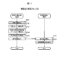
- Processing flowchart of the vehicle system 1 before the failure of the travel control device 4 according to the first embodiment Process flow diagram of function reconfiguration by the map management device 3 according to the first embodiment Processing flowchart of the vehicle system 1 when the travel control device 4 according to the first embodiment fails.
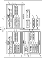
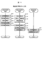
- Configuration diagram of the vehicle system 1 according to the second embodiment at normal time Configuration diagram of vehicle system 1 at the time of failure of travel control device 4 according to the second embodiment Process flow diagram of normal traveling of the vehicle system 1 before the failure of the traveling control device 4 according to the second embodiment Process flow diagram of the vehicle system 1 when the travel control device 4 according to the second embodiment fails.
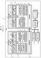
- Configuration diagram of the vehicle system 1 according to the third embodiment in a normal state Configuration diagram of vehicle system 1 at the time of failure of travel control device 4 according to the third embodiment
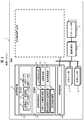
- FIG. 1 is a functional block diagram showing a configuration of a vehicle system 1 including a vehicle electronic control device according to a first embodiment of the present invention.
- the configuration shown in FIG. 1 is a normal state where no failure occurs.
- the vehicle system 1 according to the present embodiment is mounted on the vehicle 2, and recognizes the state of an obstacle such as a traveling road or a nearby vehicle around the vehicle 2 and performs appropriate driving assistance or traveling control. It is.
- the vehicle system 1 includes a map management device 3, a travel control device 4, an external sensor group 5, a vehicle sensor group 6, a motion control unit 7, and an actuator group 8.
- the map management device 3 is an ECU (Electronic Control Unit) that provides map-related information to devices mounted on the vehicle 2 such as the travel control device 4, for example, and includes a processing unit 10 and a storage unit 30. And a communication control unit 40.
- ECU Electronic Control Unit
- the processing unit 10 includes, for example, a CPU (Central Processing Unit), a GPU (Graphics Processing Unit), and an FPGA (Field-Programmable Gate Array).
- the processing unit 10 includes a host vehicle information acquisition unit 11, a road map management unit 12, a map position estimation unit 13, a peripheral route map construction unit 14, and a peripheral route map providing unit as parts for realizing the functions of the map management device 3. 15, a failure detection unit 16, and a function reconfiguration unit 17.
- the processing unit 10 realizes these functions by executing a predetermined operation program stored in the storage unit 30.
- the processing unit 10 can also realize functions different from those described above, for example, by executing different operation programs.
- the own-vehicle information acquisition unit 11 includes, as own-vehicle information related to the movement, the state, and the plan of the vehicle 2, for example, the position, traveling speed, steering angle, accelerator operation amount, brake operation amount, traveling route, and the like of the vehicle 2. Is acquired from a built-in sensor (not shown) of the map management device 3, the vehicle sensor group 6, and the like.
- the own vehicle information acquired by the own vehicle information acquiring unit 11 is stored in the storage unit 30 as the own vehicle information data group 32.
- the position of the vehicle 2 is referred to as “own vehicle position”, and information indicating the own vehicle position is also referred to as “own vehicle position information”.
- the vehicle position is, for example, a combination of latitude and longitude.
- the road map management unit 12 manages a road map data group 31 which is road map data relating to the entire area or a partial area of the destination of the vehicle 2 on the storage unit 30.
- the road map data group 31 is, for example, road map data of the entire area of the destination of the vehicle 2 and is stored in a storage device equivalent part of the storage unit 30.
- the road map management unit 12 reads road map data around the vehicle 2 from the road map data group 31 into a memory equivalent of the storage unit 30 based on the position information of the vehicle 2 acquired by the own vehicle information acquisition unit 11. This makes it possible to access road map data that needs to be processed by the map position estimating unit 13, the peripheral route map constructing unit 14, and the like.
- These road map data are stored in the storage unit 30 as a road map data group 31.
- the map position estimating unit 13 estimates a road section and a lane position where the vehicle 2 is traveling, based on the road map data group 31 around the own vehicle stored in the storage unit 30 and the own vehicle information data group 32. .
- the positions on the road and the lane on which the vehicle 2 is running, which are specified by the map position estimating unit 13, are written in a peripheral route map data group 33 described later.
- the peripheral route map construction unit 14 extracts road map data along the traveling route of the vehicle 2 and constructs peripheral route map data in which the data is structured according to a predetermined method.
- the peripheral route map data includes road map data around the vehicle 2.
- the peripheral route map data is stored in the storage unit 30 as a peripheral route map data group 33.
- the traveling route of the vehicle 2 may acquire a constructed traveling route from another device such as a navigation device.
- the travel route of the vehicle 2 may be constructed in the peripheral route map construction unit 14 by acquiring destination information set by the driver via an HMI (Human Machine Interface) device.
- HMI Human Machine Interface
- the peripheral route map providing unit 15 transmits the peripheral route map data group 33 constructed by the peripheral route map constructing unit 14 to the travel control device 4 via the communication control unit 40.
- the failure detection unit 16 monitors and detects failures of devices and functions inside the map management device 3 and devices such as the travel control device 4 outside the map management device 3. For example, the failure detection unit 16 can detect a failure of the travel control device 4 by not receiving a message normally transmitted from the travel control device 4 for a certain period of time.
- the function reconfiguring unit 17 reconfigures a function to be executed by the map management device 3 while the vehicle system 1 is operating. Reconstructing a function refers to, for example, reading a different program into a RAM when a CPU or GPU executes processing, and reconfiguring a logic circuit when an FPGA executes processing.
- the storage unit 30 is configured to include a storage device such as a hard disk drive (HDD), a flash memory, a read only memory (ROM), and a memory such as a RAM.
- the storage unit 30 stores a program processed by the processing unit 10, a data group necessary for the processing, and the like.
- the storage unit 30 is also used as a main memory when the processing unit 10 executes the program, for temporarily storing data necessary for the calculation of the program.
- a road map data group 31 a vehicle information data group 32, and a peripheral route map data group 33 are stored in the storage unit 30. .
- the road map data group 31 is a set of road map data relating to the entire area or a partial area at the destination of the vehicle 2.
- road map data for the entire area at the destination is stored in a storage device such as an HDD
- road map data around the vehicle 2 based on position information of the vehicle 2 is stored in a memory such as a RAM.
- the own vehicle information data group 32 is a set of data relating to the movement, state, plan, and the like of the vehicle 2. For example, information such as the position of the vehicle 2, the traveling speed, the steering angle, the operation amount of the accelerator, the operation amount of the brake, and the traveling route are included.
- the peripheral route map data group 33 is a set of peripheral route map data generated by the peripheral route map construction unit 14.
- the communication control unit 40 is configured to include, for example, a network card conforming to a communication standard such as IEEE802.3 or CAN (Controller Area Network, registered trademark) or the like, and to communicate with other devices in the vehicle system 1 based on various protocols. Transmission and reception.
- the communication control unit 50 is described separately from the processing unit 10, but a part of the processing of the communication control unit 50 may be executed in the processing unit 10.
- a part of the processing of the communication control unit 50 may be executed in the processing unit 10.
- the travel control device 4 plans the travel trajectory of the vehicle 2 based on, for example, map-related information provided from the map management device 3 and various sensor information provided from the external sensor group 5, the vehicle sensor group 6, and the like. And an ECU that outputs to the motion control unit 7.
- the travel control device 4 includes a processing unit 110, a storage unit 130, and a communication control unit 140.
- the processing unit 110 is configured to include, for example, a CPU, a GPU, an FPGA, and the like.
- the processing unit 110 includes a host vehicle information acquisition unit 111, an external sensor information acquisition unit 112, a peripheral route map acquisition unit 113, a traveling trajectory planning unit 114, and a traveling trajectory output as parts for realizing the functions of the traveling control device 4. It has a part 115.
- the processing unit 110 realizes these functions by executing a predetermined operation program stored in the storage unit 130.
- the own-vehicle information acquisition unit 111 includes, for example, a position, a traveling speed, a steering angle, an accelerator operation amount, a brake operation amount, and a traveling route of the vehicle 2 as the own-vehicle information related to the movement, the state, and the plan of the vehicle 2. Is obtained from the vehicle sensor group 6 and the like.
- the vehicle information acquired by the vehicle information acquiring unit 111 is stored in the storage unit 130 as a vehicle information data group 131.
- the external sensor information acquisition unit 112 acquires information on the traveling environment around the vehicle 2 detected by the external sensor group 5 from the external sensor group 5.
- the information on the traveling environment around the vehicle 2 includes other vehicles around the vehicle 2, pedestrians, obstacles such as falling objects, road environments such as white lines and roadsides, road surface conditions, and traffic signs such as road signs and signals. .
- the information obtained by the external sensor information obtaining unit 112 is stored in the storage unit 130 as an external sensor information data group 132.
- the peripheral route map acquisition unit 113 acquires the peripheral route map data output by the map management device 3.
- the acquired peripheral route map data is stored in the storage unit 130 as a peripheral route map data group 133.
- the traveling trajectory planning unit 114 based on the own vehicle information data group 131, the external sensor information data group 132, the peripheral route map data group 133, and the like stored in the storage unit 130, etc. , Called "running trajectory").
- the traveling trajectory output unit 115 outputs information of the traveling trajectory planned by the traveling trajectory planning unit 114 (hereinafter, referred to as “traveling trajectory information”) to the motion control unit 7.
- the storage unit 130 includes, for example, a storage device such as an HDD, a flash memory, and a ROM, and a memory such as a RAM.
- the storage unit 130 stores a program to be processed by the processing unit 110, a data group necessary for the processing, and the like. Further, it is also used as a main memory when the processing unit 110 executes the program, for temporarily storing data necessary for the calculation of the program.
- a storage unit 130 stores a vehicle information data group 131, an external sensor information data group 132, and a peripheral route map data group 133 as information for realizing the function of the travel control device 4.
- the self-vehicle information data group 131 is a set of data relating to the movement, state, plan, and the like of the vehicle 2.
- the host vehicle information data group 131 includes, for example, information on the position, the traveling speed, the steering angle, the accelerator operation amount, the brake operation amount, and the traveling route of the vehicle 2.
- the external sensor information data group 132 is an aggregate of data on the traveling environment around the vehicle 2 detected by the external sensor group 5.
- the peripheral route map data group 133 is a set of data relating to the peripheral route map information acquired from the map management device 3.
- the communication control unit 40 is configured to include a network card conforming to a communication standard such as IEEE802.3 or CAN, for example, and transmits and receives data to and from other devices in the vehicle system 1 based on various protocols.
- a network card conforming to a communication standard such as IEEE802.3 or CAN, for example, and transmits and receives data to and from other devices in the vehicle system 1 based on various protocols.
- the external sensor group 5 is an aggregate of devices for detecting a state around the vehicle 2, and corresponds to, for example, a camera device, a millimeter wave radar, a laser radar, a sonar, and the like. Each external sensor detects an environmental element such as an obstacle, a road environment, and a traffic sign existing in a predetermined range from the vehicle 2 and outputs the detected environmental element to a vehicle-mounted network.
- the obstacles are, for example, other vehicles, pedestrians, and obstacles that impede the traffic of vehicles.
- the vehicle sensor group 6 is an aggregate of devices for detecting the state of the vehicle 2. Each vehicle sensor detects, for example, the position information of the vehicle 2, the traveling speed, the steering angle, the operation amount of the accelerator, the operation amount of the brake, and the like, and outputs them on the on-vehicle network.
- the motion control unit 7 controls the actuator group 8 based on the traveling trajectory information output from the traveling control device 4 so that the vehicle 2 travels on the same trajectory.
- the actuator group 8 is a group of devices that controls control elements such as steering, brakes, and accelerators that determine the movement of the vehicle.
- the actuator group 8 controls the movement of the vehicle based on operation information of a driver such as a steering wheel, a brake pedal, an accelerator pedal, and the like, and control information output from the travel control device 4.
- FIG. 2 is a functional block diagram showing a configuration of the vehicle system 1 after the function reconfiguration due to the occurrence of a failure in the travel control device 4.
- the failure detection unit 16 of the map management device 3 detects the failure of the travel control device 4.
- the function reconfiguration unit 17 of the map management device 3 dynamically reconfigures the processing unit 10 of the map management device 3 and rewrites a part of the storage unit 30.
- the map management device 3 substitutes the function of the traveling control device 4 that has failed.
- the reconfiguration terminates a part of the function that has been operating up to that point, releases hardware resources (CPU, memory, etc.) used by the terminated function, and activates another function instead. That is.
- hardware resources CPU, memory, etc.
- the alternative function of the travel control device 4 is to output to the motion control unit 7 a travel trajectory that safely continues the automatic travel of the vehicle 2.
- the traveling trajectory for safely continuing automatic traveling may be a traveling trajectory for realizing automatic traveling equivalent to the traveling control device 4 or a traveling trajectory for stopping safely on a nearby road shoulder. Determined based on the concept.
- FIG. 2 shows an alternative function for safely stopping at a nearby road shoulder on a dedicated road.
- the vehicle system 1 after the failure of the traveling control device 4 can cope with the range of the peripheral route map data generated last. Is not an essential feature. Therefore, the function reconfiguring unit 17 of the map management device 3 terminates those non-essential functions, and instead, substitutes the external sensor information acquiring unit 18, the peripheral route map position estimating unit 19, the traveling trajectory planning unit 20, and the traveling The orbit output unit 21 is started.
- the memory for storing the road map data group 31 in the storage unit 30 used by the road map management unit 12 is released, and the external sensor information data group 34 is stored instead.
- the external sensor information acquisition unit 18, the peripheral route map position estimation unit 19, the traveling trajectory planning unit 20, and the traveling trajectory output unit 21 are included in the map management device 3 in a stopped state. I have.
- the function reconfiguration unit 17 performs the reconfiguration, the external sensor information acquisition unit 18, the peripheral route map position estimation unit 19, the traveling trajectory planning unit 20, and the traveling trajectory output unit 21 become operable.
- the traveling trajectory planning unit 20 and the traveling trajectory output unit 21 may be referred to as a “control unit”.
- the external sensor information acquisition unit 18 corresponds to the external sensor information acquisition unit 112 of the travel control device 4, and acquires information on the traveling environment around the vehicle 2 detected by the external sensor group 5 from the external sensor group 5.
- the outside world sensor information acquisition unit 18 may acquire information equivalent to that of the travel control device 4 or may acquire information limited to the minimum information necessary for safely stopping on a nearby road shoulder.
- the information obtained by the external sensor information obtaining unit 18 is stored in the storage unit 30 as an external sensor information data group 34.
- the peripheral route map position estimating unit 19 estimates the road section and the lane position where the vehicle 2 is traveling on the last peripheral route map data group 33 generated by the peripheral route map constructing unit 14 before the occurrence of the failure.
- the difference between the peripheral route map position estimating unit 19 and the map position estimating unit 13 is that the target data for estimating the position of the vehicle 2 is not the road map data group 31 but the peripheral route map data group 33.
- the traveling trajectory planning unit 20 corresponds to the traveling trajectory planning unit 114 of the traveling control device 4.
- the traveling trajectory planning unit 20 is based on the own vehicle information data group 32, the peripheral route map data group 33, the external sensor information data group 34, and the like stored in the storage unit 30 to safely stop at a nearby road shoulder. Plan the trajectory.
- the traveling trajectory output unit 21 corresponds to the traveling trajectory output unit 115 of the traveling control device 4, and outputs traveling trajectory information planned by the traveling trajectory planning unit 20 to the motion control unit 7.
- the motion control unit 7 controls the actuator group 8 based on the traveling trajectory information output from the traveling control device 4 before the failure of the traveling control device 4 occurs, as described above. After the failure of the travel control device 4 has occurred, the motion control unit 7 controls the actuator group 8 based on the travel trajectory information output from the map management device 3. Strictly speaking, the traveling trajectory information is not output from the time when the failure of the traveling control device 4 occurs until the alternative function of the map management device 3 outputs the traveling trajectory. However, the movement control unit 7 can maintain the automatic running for a certain time by operating based on the running trajectory information output by the running control device 4 last.
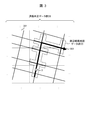
- FIG. 3 is a diagram showing the relationship between the road map data group 31 and the peripheral route map data group 33 stored in the storage unit 30 of the map management device 3.
- Each piece of road map data constituting the road map data group 31 is managed by being divided into regions (hereinafter, referred to as “parcels”) divided into meshes by predetermined distance units in the latitude and longitude directions.
- the road map data group 31 is road map data for the entire destination area of the vehicle 2.
- the road map management unit 12 stores the position information of the vehicle 2 and the road map data of the parcel where the traveling route information indicated by reference numeral 303 in FIG. 3 is located and parcels around the parcel, that is, a part of the road map data group 31 in the memory. Is read in.
- the peripheral route map data group 33 is obtained by extracting information necessary for planning a traveling trajectory in the vehicle system 1 along the traveling route of the vehicle 2 from the road map data around the vehicle 2 read into the memory and structured. It is. For example, in FIG. 3, information on roads in an area surrounded by a broken line is the peripheral route map data group 33.
- the peripheral route map data group 33 includes road sections within a predetermined distance range along the traveling route of the vehicle 2 and road shapes and road attributes related to the branch roads.
- the road shape is, for example, a road end, a white line, a lane shape, a stop line, a zebra zone, and the like.
- the road attribute is, for example, a speed limit or a traveling direction.
- the parcel contains data on all roads in the area, a large memory capacity is required to read the above-described road map data into the memory.
- what is required for planning the traveling trajectory is road map data around the road area where the vehicle 2 will travel, and only a small part of the road map data included in the parcel. Therefore, by extracting necessary information along the traveling route to generate structured peripheral route map data and transmitting the data to the traveling control device 4, unnecessary data communication on the vehicle-mounted network and the Memory consumption can be suppressed.
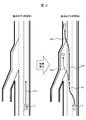
- FIG. 4 is an example of a scene when a failure occurs in the traveling road environment and the traveling control device 4.
- the left side of FIG. 4 shows the state of the automatic traveling of the vehicle 2 before the traveling control device 4 fails, and the right side of FIG. 4 shows the state of the automatic traveling of the vehicle 2 after the traveling control device 4 fails, that is, the degenerate traveling state. Is shown.
- the degraded traveling here is an automatic traveling for retreating to a nearby road shoulder and stopping.
- the vehicle 2 is traveling in an overtaking lane near the median strip, and the traveling track 411 is planned to maintain the current traveling lane. If the travel control device 4 breaks down in this state, in order to retreat to a nearby road shoulder, the lane is changed to the left lane (travel path 421) as shown by the solid line in the right diagram of FIG. It is necessary to stop shifting (running track 424). At this time, the map management device 3 needs to determine the safe stop destination after understanding the structure of the road.
- the map management device 3 stores the peripheral route map data generated by the peripheral route map construction unit 14 as a peripheral route map data group 33 in a memory. Accordingly, the traveling trajectory planning unit 20 reconstructed in the event of the failure of the traveling control device 4 can immediately refer to the nearby road map data. Can be.
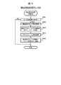
- FIG. 5 is an explanatory diagram of a processing flow of the vehicle system 1 before the failure of the travel control device 4.
- the processing flow shown in FIG. 5 is referred to as a normal traveling processing flow 500 for convenience.
- the map management device 3 periodically executes the processing of S501 to S505.
- the own-vehicle information obtaining unit 11 obtains own-vehicle information related to the movement, the state, the plan, and the like of the vehicle 2.
- the road map management unit 12 reads a road map around the vehicle 2 from the road map data group 31 into the memory based on the vehicle position information included in the vehicle information acquired in S501. At this time, the information of the road map data already stored in the memory and the information of the area whose distance has become longer due to the progress of the vehicle 2 may be deleted from the memory.
- the map position estimating unit 13 determines the vehicle 2 based on the road map data read into the memory, the traveling direction and speed of the vehicle 2 included in the own vehicle information acquired in S501, the previous calculation result, and the like. Estimate the road sections and lane positions where the vehicle is traveling.
- the peripheral route map construction unit 14 extracts road map data along the traveling route of the vehicle 2, and constructs peripheral route map data in which the data is structured according to a predetermined method.
- the travel route of the vehicle 2 is obtained from another device such as a navigation device and stored in the own vehicle information data group 32, for example.
- the constructed peripheral route map data is also stored in the memory of the map management device 3 as a peripheral route map data group 33.
- the peripheral route map providing unit 15 outputs the peripheral route map data constructed in S504 to the in-vehicle network. This peripheral route map data is used in S513 of the travel control device 4 described below.
- the traveling control device 4 periodically executes the processing shown in S511 to S515.
- the own-vehicle information acquisition unit 111 acquires own-vehicle information related to the movement, state, plan, and the like of the vehicle 2.
- the external sensor information obtaining unit 112 obtains detection information regarding the traveling environment around the vehicle 2 that is periodically output from the external sensor group 5, and stores the detection information in the external sensor information data group 132.
- the peripheral route map acquisition unit 113 acquires the peripheral route map data output from the map management device 3 and stores the data in the peripheral route map data group 133.
- the traveling trajectory planning unit 114 constructs a traveling trajectory during normal traveling based on the own vehicle information data group 131, the external sensor information data group 132, the peripheral route map data group 133, and the like stored in the storage unit 130. I do.
- the traveling trajectory output unit 115 outputs the constructed traveling trajectory to the motion control unit 7.
- the motion control unit 7 executes S521 and S522 described below.
- the movement control unit 7 acquires the traveling trajectory information periodically output by the traveling control device 4 (S521), generates a control command value for each actuator of the actuator group 8, and outputs the control command value to the actuator (S522). . Thereby, the motion control unit 7 controls the traveling of the vehicle 2.
- FIG. 6 is a diagram showing a processing flow of the function reconfiguration by the map management device 3.
- the processing flow shown in FIG. 6 is referred to as a function reconfiguration processing flow 600 for convenience.
- the failure detection unit 16 of the map management device 3 periodically monitors the traveling control device 4 and monitors whether the traveling control device 4 has failed (S601). For example, if a message periodically transmitted from the travel control device 4 is not received for a certain period of time, it is determined that the travel control device 4 has failed. When it is determined that the travel control device 4 is operating normally, the map management device 3 ends without doing anything (S601: NO). When the map management device 3 determines that the travel control device 4 is out of order, the process proceeds to S602 (S601: YES).
- the function reconfiguring unit 17 arbitrates with another device for transition to the degraded traveling mode due to the failure of the traveling control device 4.
- arbitration with other devices is unnecessary because the function is reconfigured only by the map management device 3, but when generalized, it is necessary for a plurality of devices to shift to a specific mode in line. If a mode mismatch occurs between the devices, the system does not operate. Therefore, it is necessary to perform arbitration between related devices.
- a predetermined device may determine the mode transition as a master, or each device may share its own determination result and make an autonomous determination.
- the function reconfiguring unit 17 ends some or all of the functions that are not required in the reduced drive mode, and releases hardware resources such as the CPU and the RAM used by the ended functions.
- this corresponds to the function in which the road map management unit 12, the map position estimation unit 13, the peripheral route map construction unit 14, and the peripheral route map providing unit 15 have been completed.
- the map management device 3 changes the setting of the platform. For example, when the function mounted on the map management device 3 changes, it is necessary to transmit and receive different data from the outside, but it may be necessary to change a setting on the platform side to permit the data. . Specifically, the destination to which the external sensor group 5 and the vehicle sensor group 6 output information is changed to the map management device 3, and transmission to the map management device 3 is stopped because information is unnecessary in the degraded driving mode. It is setting of thing. The setting change required for the function to be started in the next step to operate is executed here.
- step S605 the function reconfiguration unit 17 allocates hardware resources to functions required for the degraded driving mode, and activates each function.
- the external sensor information acquiring unit 18, the peripheral route map position estimating unit 19, the traveling trajectory planning unit 20, and the traveling trajectory output unit 21 are activated. As described above, the functions necessary for the degraded running shown in FIG.
- FIG. 7 is a diagram showing a processing flow of the vehicle system 1 after the failure of the traveling control device 4.
- the processing flow shown in FIG. 7 is referred to as a degenerate traveling processing flow 700 for convenience.
- the operation of the exercise control unit 7 is the same as that of the normal traveling processing flow 500, and thus the description is omitted.
- the own-vehicle information acquisition unit 11 acquires the own-vehicle information related to the movement, the state, the plan, and the like of the vehicle 2, as before the failure.
- the external sensor information acquiring unit 18 acquires the detection information on the traveling environment around the vehicle 2 that is periodically output by the external sensor group 5 and stores the detection information in the external sensor information data group 34.
- the peripheral route map position estimating unit 19 generates the peripheral route map data group last constructed by the peripheral route map constructing unit 14 before the failure based on the vehicle position information included in the vehicle information acquired in step S501.
- the position on the road and lane where the vehicle 2 is traveling is specified.
- the peripheral route map data group 33 includes the positions on the road and the lane specified by the map position estimating unit 13 before the failure.
- the internal state is lost, so it is difficult to accurately specify the road and lane positions from only the vehicle position information.
- the positions on the road and the lane specified by the map position estimating unit 13 are included in the peripheral route map data group 33. Therefore, the operation can be started from a state where the past estimated value is held, and the road and the lane position can be quickly and accurately specified based on the operation.
- the traveling trajectory planning unit 20 generates a traveling trajectory to retreat to a nearby road shoulder based on the estimation result in S703, the peripheral route map data group 33, and the external sensor information data group.
- the road environment around the vehicle 2 can be grasped from the position estimation result of the vehicle 2 with respect to the peripheral route map data group 33.
- the vehicle 2 is traveling in the right lane of the two lanes, that there is a merge from a side road in front of the vehicle 2, and the like.
- a white line, another vehicle, and a roadside can be recognized. Therefore, when the vehicle is evacuated to a nearby road shoulder as in the example of the scene in FIG. 4, the following traveling control is possible. That is, after changing the lane while observing the situation of the other vehicle in the left lane (traveling track 421 in FIG. 4), the vehicle follows the lane until it passes the merging area (traveling track 422 in FIG. 4), and then recognizes the roadside. It is possible to stop the width shift (the running track 424 in FIG. 4).
- the traveling trajectory planning unit 20 is realized by, for example, a combination of lane change (Lane Change Assistance), lane following (Lane Keep Assistance / Adaptive Cruise Control), and evacuation of the road shoulder.
- the traveling trajectory output unit 21 outputs the traveling trajectory generated in S704 to the motion control unit 7.
- the map management device 3 is a traveling trajectory planning unit 20 and a traveling trajectory output unit 21 for controlling the automatic traveling of the vehicle 2, and an information generating unit for generating peripheral route map data that is information necessary for automatic traveling.
- the function reconfiguring unit 17 lowers the function level of the peripheral route map construction unit 14 by stopping at least a part of the peripheral route map construction unit 14. Therefore, resources that are not essential for traveling of the vehicle 2 are stopped to secure resources, and resources can be allocated to the traveling trajectory planning unit 20 and the traveling trajectory output unit 21 that control the vehicle 2.
- the abnormality detected by the failure detection unit 16 is an abnormality of the traveling control device 4 that controls the automatic traveling of the vehicle 2 based on the peripheral route map data.
- the map management device 3 includes a storage unit 30 that stores the generated peripheral route map data group 33.
- the traveling path planning unit 20 and the traveling path output unit 21 control the automatic traveling of the vehicle 2 based on the peripheral route map data generated last.
- the peripheral route map data is static information of the road environment around the vehicle 2.
- the function of extracting and structuring road map data around the vehicle 2 or along a route is intended as a function unnecessary for the degraded driving after the failure of the driving control device 4. This takes advantage of the feature that, since the vehicle does not travel a long distance in the degraded traveling for evacuating to a nearby road shoulder, the range of the generated peripheral route map data can be sufficiently used. Further, since the data related to the road map is static information that does not change with the passage of time, the range necessary for the degraded traveling is held in advance, so that the processing for generating this data is unnecessary.
- Modification 1 In the above-described first embodiment, when the failure detection unit 16 detects an abnormality in the travel control device 4, the road map management unit 12, the map position estimation unit 13, the peripheral route map construction unit 14, the peripheral route map providing unit 15 Were stopped. However, only these four parts may be stopped. Alternatively, the function level may be reduced instead of stopping. Decreasing the function level means, for example, reducing the processing time of the CPU allocated to the four function blocks or reducing the amount of memory allocated to the four function blocks. According to this modification, the generation of the peripheral route map data can be continued while the functions are reduced.
- the evacuation to the nearby road shoulder has been described as an example of the degraded traveling.
- the vehicle may be compared to a portion other than the nearby road shoulder in the degraded running.
- the road map data group 31 included in the map management device 3 can be used.
- a device that handles map-related information as a candidate for a reconfiguration destination of a function necessary for degraded traveling when the traveling control device 4 fails is preferable.
- the navigation device is also suitable as a candidate for the reconstruction destination for the same reason.
- FIGS. 8 to 11 a second embodiment of the image recognition device which is an electronic control device will be described.
- the same components as those in the first embodiment are denoted by the same reference numerals, and the differences will be mainly described.
- the points that are not particularly described are the same as in the first embodiment.
- This embodiment is different from the first embodiment mainly in an apparatus for performing reconfiguration at the time of failure.
- FIG. 8 is a functional block diagram illustrating a configuration of the vehicle system 1 according to the second embodiment.
- the map management device 3 is reconfigured to have a function of realizing the degraded driving when the driving control device 4 fails, but in the second embodiment, one of the external sensor groups 5 is used.
- An image recognition device 9 performs the function.
- the vehicle system 1 includes a map management device 3, a traveling control device 4, an external sensor group 5, a vehicle sensor group 6, a motion control unit 7, an actuator group 8, and an image recognition device 9. .
- the configuration other than the image recognition device 9 is the same as that of each device of the first embodiment except for the following points. That is, in the second embodiment, the map management device 3 does not include the failure detection unit 16 and the function reconfiguration unit 17.
- the image recognition device 9 is, for example, a device that recognizes an environmental element existing around the vehicle 2, for example, another vehicle, a white line, and a roadside from imaging data acquired from one or more cameras installed in the vehicle 2. It is.
- the image recognition device 9 includes a processing unit 210, a storage unit 230, and a communication unit 240.
- the processing unit 210 includes, as functions for realizing the functions of the image recognition device 9, a front recognition unit 211, a left recognition unit 212, a right recognition unit 213, a left rear recognition unit 214, a right rear recognition unit 215, and recognition information. It has an output unit 216, a failure detection unit 217, and a function reconfiguration unit 218.
- Each of the recognizing units 211 to 215 has a function of recognizing an environmental element in a corresponding direction based on the image data acquired from the camera described above. Note that the image data need not correspond one-to-one with each direction.
- the left rear recognition unit 214 and the right rear recognition unit 215 use image data of the same camera that photographs the rear of the vehicle 2. May be processed.
- the front recognition unit 211 may acquire image data from a plurality of cameras that photograph the front, and process them in combination.
- the recognition information output unit 216 integrates the information recognized by the recognition units 211 to 215, stores the integrated information as the recognition information data group 231 in the storage unit 230, and outputs the information to the on-vehicle network.
- the travel control device 4 acquires the recognition information data group 231 as a part of the external sensor information data, and stores it in the external sensor information data group 132.
- the functions of the failure detection unit 217 and the function reconfiguration unit 218 are the same as the functions of the failure detection unit 16 and the function reconfiguration unit 17 of the map management device 3 in the first embodiment.
- the storage unit 230 stores a program to be processed by the processing unit 210, a data group necessary for the processing, and the like. Further, it is also used as a main memory when the processing unit 210 executes the program, for temporarily storing data necessary for the calculation of the program.
- the recognition information data group 231 and the like are stored in the storage unit 230 as information for realizing the function of the image recognition device 9.
- the recognition information data group 231 is a set of data on environmental elements around the vehicle 2 recognized by the recognition units 211 to 215.
- FIG. 9 is a functional block diagram illustrating a configuration of the vehicle system 1 after the function reconfiguration due to the occurrence of a failure in the travel control device 4 according to the second embodiment.
- the failure detection unit 217 of the image recognition device 9 detects that the traveling control device 4 has failed.
- the function reconfiguration unit 218 dynamically reconfigures a part of the processing unit and the storage unit of the map management device 3 to activate, that is, activate the degenerate driving function which is a substitute function of the failed driving control device 4.
- the degenerate traveling function here is an automatic traveling function for retreating to a nearby road shoulder on a dedicated road, as in the first embodiment.
- the image recognition device 9 terminates the right side recognition unit 213 and the right rear recognition unit 215 that were operating before the failure of the travel control device 4 as unnecessary functions, and instead obtains a peripheral route map acquisition unit necessary for degraded traveling.
- the peripheral route map acquisition unit 219 is equivalent to the peripheral route map acquisition unit 113 of the travel control device in FIG.
- the own vehicle information acquiring unit 220, the external sensor information acquiring unit 221, the traveling trajectory planning unit 222, and the traveling trajectory output unit 223 are provided by the own vehicle information acquiring unit of the map management device 3 of FIG. 11, the external sensor information acquisition unit 18, the traveling trajectory planning unit 20, and the traveling trajectory output unit 21.
- FIG. 10 is a diagram showing a processing flow of normal traveling of the vehicle system 1 before the failure of the traveling control device 4 in the present embodiment.
- the processing flow shown in FIG. 10 is referred to as a normal traveling processing flow 1000 for convenience.
- the operations of the map management device 3, the travel control device 4, and the motion control unit 7 are the same as those in FIG. 5 in the first embodiment, and thus description thereof will be omitted, and only the processing flow of the image recognition device 9 will be described.
- the image recognition device 9 periodically executes the processing of S1001 and S1002.
- each of the recognition units 211 to 215 recognizes an environmental element in each direction based on image data acquired from a camera mounted on the vehicle 2.
- the recognition information output unit 216 structures the information of the environment element recognized in step S1001 according to a predetermined format, and outputs the information to the vehicle-mounted network.
- the information is obtained by the external sensor information obtaining unit 112 of the travel control device 4 and stored as a part of the external sensor information data group 132 (S512).
- FIG. 11 is a diagram showing a processing flow of the vehicle system 1 after the travel control device 4 has failed.
- the processing flow shown in FIG. 10 is referred to as a degenerate traveling processing flow 1100 for convenience.
- the operations of the map management device 3 and the motion control unit 7 are the same as those of the normal traveling processing flow 1000 before the failure of the traveling control device 4, and thus the description is omitted.
- Step S1104 is the same as step S513 of the normal traveling processing flow 1000 according to the second embodiment.
- the image recognition device 9 outputs the traveling trajectory of the degenerated traveling to the motion control unit 7 instead of the traveling control device 4, and the automatic traveling can be continued.
- the processing flow in which the image recognition device 9 reconfigures the functions is the same as that in FIG.
- the function of the information generation unit that stops when an abnormality is detected is determined based on the moving direction of the vehicle 2 in the degeneration operation.
- the recognition processing of the environmental element regarding the right and rear right regions of the vehicle 2 is targeted. This is due to the feature that in degraded traveling for evacuating to a nearby road shoulder, the vehicle does not move to the right lane, and thus recognition information of the right and right rear areas is unnecessary.
- the region where the image recognition device 9 does not perform the recognition process when performing the degeneration operation may be determined based on the speed of the vehicle 2 in the degeneration operation. For example, the lower the speed of the vehicle 2, the more the recognition process needs to be performed only for an area closer to the image recognition device 9.
- a radar, a laser radar, a sonar, or the like may be used as the sensor.
- the image recognition device 9 may reduce the recognition accuracy based on the speed of the vehicle 2 in the degeneration operation.
- recognition processing of environmental elements by an external sensor involves a large amount of memory consumption and computation, so it is possible to secure enough hardware resources to incorporate the degeneration function by limiting some computations. High in nature. Therefore, when the travel control device 4 fails, the external sensor-related device is suitable as a candidate for a reconfiguration destination of a function required for degraded travel.
- FIGS. A third embodiment of the map management device, which is an electronic control device, will be described with reference to FIGS.
- the same components as those in the first embodiment are denoted by the same reference numerals, and the differences will be mainly described.
- the points that are not particularly described are the same as in the first embodiment.
- the storage unit 30 of the map management device 3 that is configured to perform the degraded traveling function when the traveling control device 4 breaks down holds the last generated peripheral route map data.
- the map management device 3 combines the external sensor information data newly output from the external sensor group 5 with the peripheral route map data, and shifts to the degraded traveling immediately after the reconfiguration. I was able to. This is effective when the external sensor information data output from the external sensor group 5 can be used as it is or can be used in a short time.
- the data acquired by sensors generally includes noise such as false detections and non-detections, it is necessary to combine multiple external sensor information data and time-series data to estimate the true value and improve the accuracy. Often available. In particular, when estimating a combination of time-series data, it takes time until the state becomes usable after the reconfiguration, and therefore, even if the degraded traveling function is reconfigured, it may not function effectively immediately.
- the dynamic peripheral map data is stored in the reconfiguration destination of the degenerate traveling function.
- the dynamic peripheral map data is a combination of a plurality of external sensor information data output from the external sensor group 5 and their time-series data. Then, after the reconfiguration of the degenerate traveling function, the vehicle immediately transitions to the degraded traveling by referring to the dynamic peripheral map data.
- FIG. 12 is a functional block diagram illustrating the configuration of the vehicle system 1 according to the third embodiment.
- the device configuration of the vehicle system 1 according to the present embodiment is the same as that of the first embodiment except for the following points. That is, in the third embodiment, in the map management device 3, the processing unit 10 further includes the dynamic peripheral map acquisition unit 22, and the storage unit 30 further includes the dynamic peripheral map data group 36. In the travel control device 4, the processing unit 110 further includes a dynamic peripheral map construction unit 117 and a dynamic peripheral map output unit 118, and the storage unit 130 further includes a dynamic peripheral map data group 134.
- the dynamic peripheral map acquisition unit 22 of the map management device 3 acquires the dynamic peripheral map data generated by the traveling control device 4 and stores the data in the dynamic peripheral map data group 36 of the storage unit 30.
- the dynamic peripheral map construction unit 117 of the traveling control device 4 constructs dynamic peripheral map data using the own vehicle information data group 131, the external sensor information data group 132, and the peripheral route map data group 133, and It is stored in the peripheral map data group 134.
- the dynamic surrounding map data is, for example, a special map that dynamically expresses a traveling environment around the vehicle 2 and is dynamically constructed by combining a plurality of external sensor information data and time series data thereof.
- the dynamic surrounding map data corresponds to, for example, a grid map in which the space around the vehicle 2 is divided into a grid and expresses the state of the place.
- the state represented in each lattice is, for example, the presence or absence of an obstacle or the sensing state. From the dynamic surrounding map data, it is possible to grasp which area the vehicle 2 can travel.
- the dynamic peripheral map output unit 118 of the traveling control device 4 outputs the dynamic peripheral map data constructed by the dynamic peripheral map construction unit 117 onto the vehicle-mounted network.
- FIG. 13 is a functional block diagram illustrating the configuration of the vehicle system 1 after the function is reconfigured due to the occurrence of a failure in the travel control device 4 according to the third embodiment.
- the failure detection unit 16 of the map management device 3 detects a failure of the traveling control device 4.
- the function reconfiguration unit 17 dynamically reconfigures a part of the processing unit and the storage unit of the map management device 3 to activate the degraded traveling function which is a substitute function of the failed traveling control device 4.
- the degenerate traveling function here is an automatic traveling function for retreating to a nearby road shoulder on a dedicated road, as in the first embodiment.
- the four functions of the road map management unit 12, the map position estimating unit 13, the peripheral route map construction unit 14, and the peripheral route map providing unit 15, which were operating before the failure of the travel control device 4, generate the peripheral route map data.
- This is a function to be provided to the travel control device 4.
- the purpose of evacuating to a nearby road shoulder on a dedicated road can be handled by the range of the peripheral route map data generated last. Is not always necessary.
- the function reconfiguring unit 17 of the map management device 3 terminates those four non-essential functions. Then, instead of the above four functions, the function reconfiguring unit 17 includes, as functions for realizing the degenerate traveling function, an external sensor information acquiring unit 18, a dynamic peripheral map position estimating unit 23, a traveling trajectory planning unit 20, And the running track output part 21 is started. At that time, the memory for storing the road map data group 31 in the storage unit 30 used by the road map management unit 12 is released, and the external sensor information data group 34 is stored instead.
- the functions of the external sensor information acquiring unit 18, the traveling trajectory planning unit 20, and the traveling trajectory output unit 21 are the same as those of the first embodiment shown in FIG. This is equivalent to the orbit output unit 21.
- the dynamic peripheral map position estimating unit 23 updates the information on the position and orientation of the vehicle 2 based on the dynamic peripheral map data acquired last from the travel control device 4. Since the position of a stationary obstacle such as a roadside is represented in the dynamic peripheral map data, the position of the stationary obstacle included in the external sensor information data newly acquired from the external sensor group 5 is collated. Accordingly, the dynamic peripheral map position estimating unit 23 updates the information on the position and the attitude of the vehicle 2 in the dynamic peripheral map data.
- the dynamic peripheral map construction unit 24 reflects the newly acquired external sensor information data on the dynamic peripheral map data based on the position and orientation of the vehicle 2 specified by the dynamic peripheral map position estimation unit 23.
- the processing of the dynamic peripheral map position estimating unit 23 and the dynamic peripheral map constructing unit 24 can be realized by applying a technique generally called SLAM (Simultaneous Localization and Mapping).
- SLAM Simultaneous Localization and Mapping
- the map management device 3 stores the storage unit 30 that stores the dynamic peripheral map data group 36 generated by integrating the peripheral route map data group 33 with the recognition information acquired from the sensor by the traveling control device 4. Prepare. The traveling trajectory planning unit 20 and the traveling trajectory output unit 21 control automatic traveling based on the dynamic peripheral map data group 33. The map management device 3 always acquires and holds the dynamic peripheral map data generated by the travel control device 4, so that even if the travel control device 4 fails and the degraded travel function is reconfigured, the travel control device 4 The traveling environment information around the vehicle 2 recognized by the device 4 can be quickly restored.
- the traveling trajectory planning unit 20 and the traveling trajectory output unit 21 each include an external sensor information acquiring unit 18 that acquires recognition information from a part of the sensor.
- the traveling trajectory planning unit 20 and the traveling trajectory output unit 21 control the automatic traveling of the vehicle 2 based on the dynamic surrounding map data group 33 and the recognition information. Therefore, even if it is necessary to plan the traveling trajectory after highly accurately recognizing the traveling environment around the vehicle 2 by combining a plurality of external sensor information data and time series data, the degraded traveling can be quickly performed after the function is reconfigured. The transition can be made, and the safety of the vehicle system 1 can be improved.
- each process is described as being executed by the same processing unit and storage unit, but may be executed by a plurality of different processing units and storage units. .
- processing software having a similar configuration is installed in each storage unit, and the processing is shared and executed by each processing unit.
- the processes of the map management device 3 are realized by executing a predetermined operation program using a processor and a RAM, but may be realized by original hardware as needed. Further, in the above-described embodiment, the map management device, the travel control device, the external sensor group, the vehicle sensor group, the motion control unit, and the actuator group are described as individual devices. It is also possible to realize by combining two or more.
Landscapes
- Engineering & Computer Science (AREA)
- Automation & Control Theory (AREA)
- Transportation (AREA)
- Mechanical Engineering (AREA)
- Physics & Mathematics (AREA)
- Human Computer Interaction (AREA)
- Remote Sensing (AREA)
- Radar, Positioning & Navigation (AREA)
- General Physics & Mathematics (AREA)
- Mathematical Physics (AREA)
- Theoretical Computer Science (AREA)
- Multimedia (AREA)
- Traffic Control Systems (AREA)
- Control Of Driving Devices And Active Controlling Of Vehicle (AREA)
- Navigation (AREA)
- Steering Control In Accordance With Driving Conditions (AREA)
Abstract
電子制御装置は、車両の自動走行を制御する制御部と、自動走行に必要な情報を生成する情報生成部と、異常を検出する異常検出部と、異常検出部が異常を検出すると、情報生成部の機能レベルを低下させ、制御部を起動する機能再構成部と、を備える。
Description
本発明は、電子制御装置に関する。
近年、車両の快適で安全な自動運転を実現するため、車両システムの一部が故障しても安全に退避制御を可能とする技術が提案されている。特許文献1には、自車両が走行する走行環境情報を取得する走行環境情報取得手段と、自車両の走行情報を検出する走行情報検出手段とを備え、上記走行環境情報と上記自車両の走行情報に基づいて自動運転制御を実行する車両の走行制御装置において、上記走行環境情報取得手段とは異なる、自車両周辺の物体を検出する自車両周辺物体検出手段と、上記走行環境情報取得手段の異常を検出する環境情報取得異常検出手段と、上記走行環境情報取得の異常を検出した際には、上記走行環境情報の取得が異常になる前の最後に検出した走行環境情報と上記走行情報とに基づいて自車両を路側に退避させる進行路を目標進行路として設定して自車両を路側に自動運転で退避させる退避制御を実行すると共に、上記自車両周辺物体検出手段を起動し、上記自車両周辺物体検出手段で自車両周辺の物体を検出した場合には、該自車両周辺の物体情報と上記走行環境情報の取得が異常になる前の最後に検出した走行環境情報と上記走行情報に基づいて上記退避制御を実行する退避制御手段と、を備えたことを特徴とする車両の走行制御装置が開示されている。
特許文献1に記載されている発明では、走行制御装置の失陥時にも車両を制御可能とするためには走行制御装置の冗長実行が必要となる。
本発明の第1の態様による電子制御装置は、車両の自動走行を制御する制御部と、自動走行に必要な情報である周辺経路地図データを生成する情報生成部と、異常を検出する異常検出部と、前記異常検出部が異常を検出すると、前記情報生成部の機能レベルを低下させ、前記制御部を起動する機能再構成部と、を備える。
本発明によれば、走行制御装置を冗長実行することなく、走行制御装置の失陥時にも車両が制御可能である。
―第1の実施の形態―
以下、図1~図7を参照して、電子制御装置である地図管理装置3の第1の実施の形態を説明する。
以下、図1~図7を参照して、電子制御装置である地図管理装置3の第1の実施の形態を説明する。
(通常時の構成)
図1は、本発明の第1の実施の形態に係る車両用電子制御装置を含む車両システム1の構成を示す機能ブロック図である。ただし図1に示す構成は故障が生じていない通常時のものである。本実施形態に係る車両システム1は、車両2に搭載され、車両2の周辺における走行道路や周辺車両などの障害物の状況を認識した上で、適切な運転支援あるいは走行制御を行うためのシステムである。図1に示すように、車両システム1は、地図管理装置3、走行制御装置4、外界センサ群5、車両センサ群6、運動制御部7、およびアクチュエータ群8を含んで構成される。
図1は、本発明の第1の実施の形態に係る車両用電子制御装置を含む車両システム1の構成を示す機能ブロック図である。ただし図1に示す構成は故障が生じていない通常時のものである。本実施形態に係る車両システム1は、車両2に搭載され、車両2の周辺における走行道路や周辺車両などの障害物の状況を認識した上で、適切な運転支援あるいは走行制御を行うためのシステムである。図1に示すように、車両システム1は、地図管理装置3、走行制御装置4、外界センサ群5、車両センサ群6、運動制御部7、およびアクチュエータ群8を含んで構成される。
(システム構成 地図管理装置3)
地図管理装置3は、たとえば走行制御装置4など、車両2に搭載された装置に対して地図関連情報を提供するECU(Electronic Control Unit:電子制御装置)であり、処理部10と、記憶部30と、通信制御部40とを備える。
地図管理装置3は、たとえば走行制御装置4など、車両2に搭載された装置に対して地図関連情報を提供するECU(Electronic Control Unit:電子制御装置)であり、処理部10と、記憶部30と、通信制御部40とを備える。
処理部10は、たとえば、CPU(Central Processing Unit:中央演算処理装置)、GPU(Graphics Processing Unit)、FPGA(Field-Programmable Gate Array)を含んで構成される。処理部10は、地図管理装置3の機能を実現するための部分として、自車情報取得部11、道路地図管理部12、地図位置推定部13、周辺経路地図構築部14、周辺経路地図提供部15、故障検出部16、および機能再構成部17を有する。処理部10は、記憶部30に格納されている所定の動作プログラムを実行することで、これらの機能を実現する。処理部10は、たとえば異なる動作プログラムを実行することで、後述するように上述したものとは異なる機能を実現することもできる。
自車情報取得部11は、車両2の動きや状態、計画などに関連する自車情報として、たとえば車両2の位置、走行速度、操舵角、アクセルの操作量、ブレーキの操作量、走行経路などの情報を、地図管理装置3の不図示の内蔵センサや、車両センサ群6などから取得する。自車情報取得部11により取得された自車情報は、自車情報データ群32として記憶部30に格納される。なお以下では、車両2の位置を「自車位置」と呼び、自車位置を示す情報を「自車位置情報」とも呼ぶ。なお自車位置はたとえば緯度と経度の組み合わせである。
道路地図管理部12は、車両2の仕向け地における全域または部分領域に関する道路地図データである道路地図データ群31を記憶部30上で管理する。道路地図データ群31は、たとえば車両2の仕向け地における全域の道路地図データであり、記憶部30の記憶装置相当部に保存される。道路地図管理部12は、自車情報取得部11により取得された車両2の位置情報に基づいて、道路地図データ群31から車両2周辺の道路地図データを記憶部30のメモリ相当部に読み込む。これにより、地図位置推定部13、周辺経路地図構築部14などの処理が必要な道路地図データにアクセス可能となる。これらの道路地図データは、道路地図データ群31として記憶部30に格納される。
地図位置推定部13は、記憶部30に格納された自車周辺の道路地図データ群31と、自車情報データ群32に基づいて、車両2が走行している道路区間や車線位置を推定する。地図位置推定部13が特定した、車両2が走行している道路および車線上の位置は、後述する周辺経路地図データ群33に書き込まれる。
周辺経路地図構築部14は、車両2の走行経路に沿って道路地図データを抽出し、所定の方式に従い当該データを構造化した周辺経路地図データを構築する。換言すると、周辺経路地図データは車両2の周辺の道路地図データを含む。周辺経路地図データは、周辺経路地図データ群33として記憶部30に格納される。車両2の走行経路は、たとえばナビゲーション装置などの他装置から構築済みの走行経路を取得してもよい。また車両2の走行経路は、運転者がHMI(Human Machine Interface)装置経由で設定した目的地情報を取得して、周辺経路地図構築部14の中で構築してもよい。さらに車両2の走行経路は、特定の目的地なしで道なりに沿ったものを仮想的な走行経路として扱ってもよい。
周辺経路地図提供部15は、周辺経路地図構築部14が構築した周辺経路地図データ群33を、通信制御部40を介して走行制御装置4に送信する。故障検出部16は、地図管理装置3内部のデバイスや機能、走行制御装置4などの地図管理装置3外部の装置の故障を監視・検出する。故障検出部16はたとえば、本来であれば定期的に走行制御装置4から送信されるメッセージを一定時間受信しないことにより、走行制御装置4の故障を検出することが可能である。
機能再構成部17は、車両システム1が動作している状況下において、地図管理装置3で実行する機能を再構成する。機能の再構築とは、たとえばCPUやGPUが処理を実行する場合にはRAMへ異なるプログラムを読み込むことであり、FPGAが処理を実行する場合には論理回路を再構成することである。
記憶部30は、たとえば、HDD(Hard Disk Drive)、フラッシュメモリ、ROM(Read Only Memory)などの記憶装置や、RAMなどのメモリを含んで構成される。記憶部30には、処理部10が処理するプログラムや、その処理に必要なデータ群などが格納される。また記憶部30は、処理部10がプログラムを実行する際の主記憶として、一時的にプログラムの演算に必要なデータを格納する用途にも利用される。本実施の形態では、特に、地図管理装置3の機能を実現するための情報として、道路地図データ群31、自車情報データ群32、および周辺経路地図データ群33が記憶部30に格納される。
道路地図データ群31は、車両2の仕向け地における全域または部分領域に関する道路地図データの集合である。たとえば、HDDなどの記憶装置に仕向け地における全域に関する道路地図データが格納され、車両2の位置情報に基づいた車両2周辺の道路地図データがRAMなどのメモリに格納されている。自車情報データ群32は、車両2の動きや状態、計画などに関するデータの集合である。たとえば車両2の位置、走行速度、操舵角、アクセルの操作量、ブレーキの操作量、走行経路などの情報が含まれる。
周辺経路地図データ群33は、周辺経路地図構築部14が生成する周辺経路地図データの集合である。通信制御部40は、たとえば、IEEE802.3またはCAN(Controller Area Network、登録商標)などの通信規格に準拠したネットワークカードなどを含んで構成され、車両システム1における他の装置と各種プロトコルに基づきデータの送受信を行う。
なお、本実施形態では、通信制御部50を処理部10と分けて記載しているが、処理部10の中で通信制御部50の処理の一部が実行されてもよい。たとえば、通信処理におけるハードウェアデバイス相当が通信制御部50に位置し、それ以外のデバイスドライバ群や通信プロトコル処理などは、処理部10の中に位置するように構成することも可能である。
(システム構成 走行制御装置4)
走行制御装置4は、たとえば、地図管理装置3から提供される地図関連情報や、外界センサ群5、車両センサ群6などから提供される各種センサ情報などに基づいて、車両2の走行軌道を計画し、運動制御部7に出力するECUである。走行制御装置4は、処理部110と、記憶部130と、通信制御部140とを備える。
走行制御装置4は、たとえば、地図管理装置3から提供される地図関連情報や、外界センサ群5、車両センサ群6などから提供される各種センサ情報などに基づいて、車両2の走行軌道を計画し、運動制御部7に出力するECUである。走行制御装置4は、処理部110と、記憶部130と、通信制御部140とを備える。
処理部110は、たとえば、CPU、GPU、FPGAなどを含んで構成される。処理部110は、走行制御装置4の機能を実現するための部分として、自車情報取得部111、外界センサ情報取得部112、周辺経路地図取得部113、走行軌道計画部114、および走行軌道出力部115を有する。処理部110は、記憶部130に格納されている所定の動作プログラムを実行することで、これらの機能を実現する。
自車情報取得部111は、車両2の動きや状態、計画などに関連する自車情報として、たとえば車両2の位置、走行速度、操舵角、アクセルの操作量、ブレーキの操作量、および走行経路などの情報を、車両センサ群6などから取得する。自車情報取得部111により取得された自車情報は、自車情報データ群131として記憶部130に格納される。
外界センサ情報取得部112は、外界センサ群5によって検出された車両2周辺の走行環境に関する情報を、外界センサ群5から取得する。車両2周辺の走行環境に関する情報とは、車両2周辺の他車両、歩行者、落下物などの障害物、白線や路端、路面状態などの道路環境、道路標識や信号などの交通標識を含む。外界センサ情報取得部112により取得された情報は、外界センサ情報データ群132として記憶部130に格納される。
周辺経路地図取得部113は、地図管理装置3により出力された周辺経路地図データを取得する。取得された周辺経路地図データは、周辺経路地図データ群133として記憶部130に格納される。
走行軌道計画部114は、記憶部130に格納された自車情報データ群131、外界センサ情報データ群132、および周辺経路地図データ群133などに基づいて、車両2がこれから走行すべき軌道(以下、「走行軌道」と呼ぶ)を計画する。走行軌道出力部115は、走行軌道計画部114が計画した走行軌道の情報(以下、「走行軌道情報」と呼ぶ)を運動制御部7に出力する。
記憶部130は、たとえば、HDD、フラッシュメモリ、ROMなどの記憶装置や、RAMなどのメモリを含んで構成される。記憶部130は、処理部110が処理するプログラムや、その処理に必要なデータ群などが格納される。また、処理部110がプログラムを実行する際の主記憶として、一時的にプログラムの演算に必要なデータを格納する用途にも利用される。本実施形態では、走行制御装置4の機能を実現するための情報として、自車情報データ群131、外界センサ情報データ群132、および周辺経路地図データ群133が記憶部130に格納される。
自車情報データ群131は、車両2の動きや状態、計画などに関するデータの集合である。自車情報データ群131にはたとえば、車両2の位置、走行速度、操舵角、アクセルの操作量、ブレーキの操作量、および走行経路の情報が含まれる。外界センサ情報データ群132は、外界センサ群5によって検出された車両2周辺の走行環境に関するデータの集合体である。周辺経路地図データ群133は、地図管理装置3から取得した周辺経路地図情報に関するデータの集合である。
通信制御部40は、たとえば、IEEE802.3またはCANなどの通信規格に準拠したネットワークカードを含んで構成され、車両システム1における他の装置と各種プロトコルに基づきデータの送受信を行う。
外界センサ群5は、車両2周辺の状態を検出する装置の集合体で、たとえば、カメラ装置、ミリ波レーダ、レーザレーダ、ソナーなどが該当する。各外界センサは、車両2から所定範囲に存在する障害物、道路環境、および交通標識などの環境要素を検出し、車載ネットワーク上に出力する。障害物とはたとえば他の車両、歩行者、および車両の通行を妨げる障害物である。
車両センサ群6は、車両2の状態を検出する装置の集合体である。各車両センサは、たとえば、車両2の位置情報、走行速度、操舵角、アクセルの操作量、ブレーキの操作量などを検出し、車載ネットワーク上に出力する。運動制御部7は、走行制御装置4から出力された走行軌道情報に基づき、車両2が同軌道を走行するようにアクチュエータ群8を制御する。
アクチュエータ群8は、車両の動きを決定する操舵、ブレーキ、アクセルなどの制御要素を制御する装置群である。アクチュエータ群8は、運転者によるハンドル、ブレーキペダル、アクセルペダルなどの操作情報や走行制御装置4から出力される制御情報に基づいて、車両の動きを制御する。
(故障時の構成)
図2は、走行制御装置4の故障発生による機能再構成後の車両システム1の構成を示す機能ブロック図である。本実施形態では、走行制御装置4が故障すると、地図管理装置3の故障検出部16が走行制御装置4の故障を検出する。そして地図管理装置3の機能再構成部17が、地図管理装置3の処理部10を動的に再構成し、記憶部30の一部を書き換える。これにより地図管理装置3は、故障した走行制御装置4の機能を代替する。
図2は、走行制御装置4の故障発生による機能再構成後の車両システム1の構成を示す機能ブロック図である。本実施形態では、走行制御装置4が故障すると、地図管理装置3の故障検出部16が走行制御装置4の故障を検出する。そして地図管理装置3の機能再構成部17が、地図管理装置3の処理部10を動的に再構成し、記憶部30の一部を書き換える。これにより地図管理装置3は、故障した走行制御装置4の機能を代替する。
ここで再構成とは、それまで動作していた機能の一部を終了し、終了させた機能が利用していたハードウェアリソース(CPU、メモリなど)を解放し、代わりに別機能を起動することである。なお、解放する対象となるハードウェアリソースはさまざまであり、たとえばCPUのみを開放する場合には、予め起動対象のプログラムをメモリ上に入れておいて演算処理を切り替える。またCPUだけでなくメモリも開放する場合には、メモリに読み込んだプログラムを削除し演算処理も切り替える。
走行制御装置4の代替機能とは、車両2の自動走行を安全に継続する走行軌道を運動制御部7に出力するものである。自動走行を安全に継続する走行軌道とは、走行制御装置4と同等の自動走行を実現する走行軌道でもよいし、近傍の路肩に安全に停止するための走行軌道でもよく、車両システム1の安全コンセプトに基づき決定される。図2では、専用道において近傍の路肩に安全に停止するための代替機能を対象としている。
走行制御装置4の故障前、すなわち図1に示した通常時に動作していた道路地図管理部12、地図位置推定部13、周辺経路地図構築部14、および周辺経路地図提供部15は、周辺経路地図データを生成し、走行制御装置4に提供する機能を有する。しかし、近傍の路肩に安全に停止するための走行軌道を構築する目的においては、最後に生成した周辺経路地図データの範囲で対応可能であるため、走行制御装置4が故障した後の車両システム1には必須の機能ではない。そこで、地図管理装置3の機能再構成部17は、それらの必須ではない機能を終了させ、代わりに、外界センサ情報取得部18、周辺経路地図位置推定部19、走行軌道計画部20、および走行軌道出力部21を起動する。その際に、道路地図管理部12が利用していた記憶部30の道路地図データ群31を格納するためのメモリを解放し、代わりに外界センサ情報データ群34を格納する。
すなわち図1では説明しなかったが、外界センサ情報取得部18、周辺経路地図位置推定部19、走行軌道計画部20、および走行軌道出力部21は、地図管理装置3に停止状態で含まれている。機能再構成部17が再構成を行うことで、外界センサ情報取得部18、周辺経路地図位置推定部19、走行軌道計画部20、および走行軌道出力部21は動作可能となる。また以下では、走行軌道計画部20および走行軌道出力部21を「制御部」と呼ぶこともある。
外界センサ情報取得部18は、走行制御装置4の外界センサ情報取得部112に相当し、外界センサ群5によって検出された車両2周辺の走行環境に関する情報を、外界センサ群5から取得する。外界センサ情報取得部18は、走行制御装置4と同等の情報を取得してもよいし、近傍の路肩に安全に停止するために必要最小限の情報に限定して取得してもよい。外界センサ情報取得部18により取得された情報は、外界センサ情報データ群34として記憶部30に格納される。
周辺経路地図位置推定部19は、故障発生前の周辺経路地図構築部14が生成した最後の周辺経路地図データ群33上で、車両2が走行している道路区間や車線位置を推定する。周辺経路地図位置推定部19と地図位置推定部13との違いは、車両2の位置を推定する対象データが、道路地図データ群31ではなく周辺経路地図データ群33である点である。
走行軌道計画部20は、走行制御装置4の走行軌道計画部114に相当する。走行軌道計画部20は、記憶部30に格納された自車情報データ群32、周辺経路地図データ群33、および外界センサ情報データ群34などに基づいて、近傍の路肩に安全に停止するための走行軌道を計画する。走行軌道出力部21は、走行制御装置4の走行軌道出力部115に相当し、走行軌道計画部20が計画した走行軌道情報を運動制御部7に出力する。
運動制御部7は、走行制御装置4の故障発生前は、前述のように走行制御装置4から出力される走行軌道情報に基づきアクチュエータ群8を制御する。運動制御部7は、走行制御装置4の故障発生後は、地図管理装置3から出力される走行軌道情報に基づきアクチュエータ群8を制御する。なお厳密には、走行制御装置4の故障発生時点から、地図管理装置3の代替機能が走行軌道を出力するまでの間、走行軌道情報が出力されない状態となる。しかし運動制御部7は、走行制御装置4が最後に出力した走行軌道情報に基づき動作することにより、ある程度の時間は自動走行を維持することは可能である。
(道路地図データ群31と周辺経路地図データ群33の関係)
図3は、地図管理装置3の記憶部30に格納されている道路地図データ群31と周辺経路地図データ群33の関係を示す図である。
図3は、地図管理装置3の記憶部30に格納されている道路地図データ群31と周辺経路地図データ群33の関係を示す図である。
道路地図データ群31を構成するそれぞれの道路地図データは、緯度・経度方向の所定距離単位でメッシュ状に区切られた領域(以下、「パーセル」と呼ぶ)に分割されて管理されている。道路地図データ群31は、車両2の仕向け地の全域に関する道路地図データである。道路地図管理部12により、車両2の位置情報や、図3に符号303で示す走行経路情報が位置するパーセルおよびその周辺のパーセルの道路地図データ、すなわち道路地図データ群31の一部がメモリ上に読み込まれる。
周辺経路地図データ群33は、メモリに読み込まれた車両2周辺の道路地図データから、車両2の走行経路に沿って車両システム1における走行軌道の計画に必要な情報を抽出し、構造化したものである。たとえば、図3中では、破線で囲まれた領域内の道路に係る情報が周辺経路地図データ群33である。周辺経路地図データ群33には、車両2の走行経路に沿って、所定距離範囲の道路区間とその分岐路に係る道路形状や道路属性などが含まれる。道路形状とはたとえば、路端、白線、車線形状、停止線、およびゼブラゾーンなどである。道路属性とはたとえば、制限速度や進行方向などである。
パーセル内には、その領域内の全ての道路に関するデータが含まれるため、上述した範囲の道路地図データをメモリ上に読み込むためには、大きなメモリ容量が必要となる。しかし、走行軌道の計画で必要となるのは、車両2がこれから走行する道路領域周辺の道路地図データであり、パーセル内に含まれる道路地図データのごく一部である。そこで、走行経路に沿って必要な情報を抽出して構造化した周辺経路地図データを生成し、走行制御装置4に送信することにより、車載ネットワーク上の不要なデータ通信や、走行制御装置4におけるメモリ消費を抑制できる。
(シーン例)
図4は、走行道路環境と走行制御装置4の故障発生時のシーンの一例である。図4の左側は走行制御装置4が故障する前の車両2の自動走行の様子を示し、図4の右側は走行制御装置4が故障した後の車両2の自動走行、すなわち縮退走行の様子を示している。ここでの縮退走行は、近傍の路肩に退避して停止するための自動走行である。
図4は、走行道路環境と走行制御装置4の故障発生時のシーンの一例である。図4の左側は走行制御装置4が故障する前の車両2の自動走行の様子を示し、図4の右側は走行制御装置4が故障した後の車両2の自動走行、すなわち縮退走行の様子を示している。ここでの縮退走行は、近傍の路肩に退避して停止するための自動走行である。
図4の左図では、車両2は中央分離帯寄りの追い越し車線を走行しており、現在の走行車線を維持するように走行軌道411が計画されている。この状態で走行制御装置4が故障すると、近傍の路肩に退避するためには、図4右図に実線で示すように、左側の車線に車線変更してから(走行軌道421)、路肩に幅寄せ停止(走行軌道424)する必要がある。この際に地図管理装置3は、道路の構造を理解した上で安全な停止先を判断する必要がある。
たとえば、図4の走行道路環境において、左側の車線に車線変更後すぐに路肩への幅寄せ停止を行うと、走行軌道423のように、合流用車線に入り込んでしまい、他車両との衝突や他車両による本線合流を妨害するリスクがある。そのため、合流地点が近くにあることを事前に把握し、合流地点を通過した後で、路肩に幅寄せ停止する走行軌道計画が必要である。合流地点の存在を外界センサ群5の出力を用いて、十分前もって認識するのは難しく、これらの情報は道路地図データ、具体的には周辺経路地図データを用いて把握するのが好適である。
そのため地図管理装置3は、周辺経路地図構築部14が生成する周辺経路地図データを周辺経路地図データ群33としてメモリ上に保持しておく。これにより、走行制御装置4の故障時に再構成された走行軌道計画部20は、直ちに近傍の道路地図データを参照できるため、合流地点を回避して路肩に幅寄せ停止する走行軌道を生成することができる。
(フローチャート)
図5~図7を参照して、走行制御装置4の故障前後の地図管理装置3、走行制御装置4、および運動制御部7の処理の流れを説明する。
図5~図7を参照して、走行制御装置4の故障前後の地図管理装置3、走行制御装置4、および運動制御部7の処理の流れを説明する。
図5は、走行制御装置4の故障前の車両システム1の処理フローの説明図である。本実施の形態では、図5に示す処理フローを便宜的に通常走行処理フロー500と呼ぶ。地図管理装置3は、通常時にはS501~S505の処理を周期的に実行する。
まずS501において、自車情報取得部11が、車両2の動きや状態、計画などに関連する自車情報を取得する。続いてS502において、道路地図管理部12が、S501において取得した自車情報に含まれる自車位置情報に基づいて、道路地図データ群31から車両2の周辺の道路地図をメモリに読み込む。なおこの際に、メモリに格納済みの道路地図データであって車両2の進行により距離が遠くなった領域の情報をメモリから削除してもよい。
次に地図位置推定部13は、S503において、メモリに読み込まれた道路地図データと、S501で取得した自車情報に含まれる車両2の進行方位や速度、前回の算出結果などに基づき、車両2が走行している道路区間や車線の位置を推定する。S504では、周辺経路地図構築部14が車両2の走行経路に沿って道路地図データを抽出し、所定の方式に従い当該データを構造化した周辺経路地図データを構築する。
車両2の走行経路は、たとえば、ナビゲーション装置などの他の装置から取得され、自車情報データ群32に格納されている。また、構築された周辺経路地図データは、周辺経路地図データ群33として、地図管理装置3のメモリ上にも格納される。そして最後にS505では、周辺経路地図提供部15が、S504において構築された周辺経路地図データを車載ネットワーク上に出力する。この周辺経路地図データは、次に説明する走行制御装置4のS513において利用される。
走行制御装置4では、S511~S515に示す処理を周期的に実行する。まず、S511で、自車情報取得部111が、車両2の動きや状態、計画などに関連する自車情報を取得する。続いてS512では、外界センサ情報取得部112が、外界センサ群5から定期的に出力される車両2周辺の走行環境に関する検出情報を取得し、外界センサ情報データ群132に格納する。S513では、周辺経路地図取得部113が、地図管理装置3から出力された周辺経路地図データを取得し、周辺経路地図データ群133に格納する。
S514では、走行軌道計画部114が、記憶部130に格納された自車情報データ群131、外界センサ情報データ群132、周辺経路地図データ群133などに基づいて、通常走行時の走行軌道を構築する。そして最後に、S515では、走行軌道出力部115が、構築した走行軌道を運動制御部7に出力する。
運動制御部7は、走行制御装置4が前述のS515の処理により走行軌道を出力すると、次に説明するS521およびS522を実行する。運動制御部7は、走行制御装置4が定期的に出力する走行軌道情報を取得し(S521)、アクチュエータ群8の各アクチュエータに対する制御指令値を生成し、該アクチュエータに対して出力(S522)する。これにより運動制御部7は、車両2の走行を制御する。
図6は、地図管理装置3による機能再構成の処理フローを示す図である。本実施の形態では、図6に示す処理フローを便宜的に機能再構成処理フロー600と呼ぶ。
地図管理装置3の故障検出部16は、定期的に走行制御装置4を監視し、走行制御装置4が故障しているか否かを監視する(S601)。たとえば、走行制御装置4から定期的に送信されるメッセージが一定時間受信しないと、走行制御装置4が故障していると判断する。地図管理装置3は、走行制御装置4が正常に動作していると判断する場合は何もせずに終了する(S601:NO)。地図管理装置3は、走行制御装置4が故障していると判断する場合は、S602に進む(S601:YES)。
S602では、機能再構成部17が、走行制御装置4の故障による縮退走行モードへの移行について、他装置と調停する。本実施形態では、地図管理装置3のみで機能の再構成を行うため他装置との調停は不要だが、一般化すると複数の装置で特定のモードに足並みをそろえて移行する必要がある。装置間にモードの不一致が生じるとシステムが動作しなくなるため、関係する装置間で調停を行う必要がある。調停の方式としては、所定の装置がマスターとしてモード移行を判断してもよいし、各装置が自分の判断結果を共有して自律的に判断してもよい。
続いてS603では機能再構成部17が、縮退走行モードにおいて不要となる機能の一部またはすべてを終了し、終了した機能が使用していたCPUやRAMなどのハードウェアリソースを解放する。本実施形態では、道路地図管理部12、地図位置推定部13、周辺経路地図構築部14、周辺経路地図提供部15が終了した機能に該当する。
S604では、地図管理装置3がプラットフォームの設定を変更する。たとえば、地図管理装置3に搭載する機能が変わることにより、それまでとは異なるデータを外部と送受信する必要があるが、それを許可するようにプラットフォーム側の設定を変更しなければならない場合がある。具体的には、外界センサ群5や車両センサ群6が情報を出力する宛先を地図管理装置3に変更することや、縮退走行モードでは情報が不要なため地図管理装置3への送信を停止させることの設定である。次ステップで起動する機能が動作するために必要な設定変更をここで実行する。
そしてS605で、機能再構成部17が縮退走行モードに必要となる機能にハードウェアリソースを割り当てて、それぞれの機能を起動する。本実施形態では、外界センサ情報取得部18、周辺経路地図位置推定部19、走行軌道計画部20、走行軌道出力部21を起動する。以上により、図4に示した縮退走行に必要な機能が地図管理装置3で再構成される。
図7は、走行制御装置4の故障後の車両システム1の処理フローを示す図である。本実施の形態では、図7に示す処理フローを便宜的に縮退走行処理フロー700と呼ぶ。ただし運動制御部7の動作は通常走行処理フロー500と同様なので説明を省略する。
S501では、故障前と同様に、自車情報取得部11が、車両2の動きや状態、計画などに関連する自車情報を取得する。S702では、外界センサ情報取得部18が、外界センサ群5によって定期的に出力される車両2周辺の走行環境に関する検出情報を取得し、外界センサ情報データ群34に格納する。
S703では、周辺経路地図位置推定部19が、S501で取得した自車情報に含まれる自車位置情報に基づいて、故障前の周辺経路地図構築部14によって最後に構築された周辺経路地図データ群33における、車両2が走行している道路および車線上の位置を特定する。なお前述のとおり、周辺経路地図データ群33には、故障前に地図位置推定部13が特定した道路および車線上の位置が含まれている。
一般に、機能を再構成した直後は、内部状態が失われているため、自車位置情報のみから正確に道路および車線位置を特定するのは難しい。しかし本実施の形態では地図位置推定部13が特定した道路および車線上の位置が周辺経路地図データ群33に含まれる。そのため、過去の推定値が保持されている状態から動作を開始することができ、これを手がかりに高速かつ正確に道路および車線位置を特定することができる。
S704では、走行軌道計画部20が、S703の推定結果、周辺経路地図データ群33、および外界センサ情報データ群34に基づき、近傍の路肩に退避する走行軌道を生成する。周辺経路地図データ群33に対する車両2の位置推定結果から、車両2周辺の道路環境を把握することが可能である。
たとえば、図4の状況下において、車両2が2車線中の右車線を走行していることや、車両2のすぐ前方に側路からの合流があることなどを把握できる。また、外界センサ情報データ群34が出力する情報を用いて、白線や他車両、路端を認識することができる。そのため、図4のシーンの例のように、近傍の路肩に退避する際には次のような走行制御が可能となる。すなわち、左車線の他車両の状況を見ながら車線変更した上で(図4の走行軌道421)、合流領域を通過するまで車線追従し(図4の走行軌道422)、その後路端を認識しながら幅寄せ停止する(図4の走行軌道424)ことが可能となる。
このように、走行軌道計画部20は、たとえば、車線変更(Lane Change Assistance)、車線追従(Lane Keep Assistance / Adaptive Cruise Control)、路肩退避の組合せにより実現される。そして最後に、S705で、走行軌道出力部21が、S704で生成された走行軌道を運動制御部7に出力する。
上述した第1の実施の形態によれば、次の作用効果が得られる。
(1)地図管理装置3は、車両2の自動走行を制御する走行軌道計画部20および走行軌道出力部21と、自動走行に必要な情報である周辺経路地図データを生成する情報生成部である周辺経路地図構築部14と、走行制御装置4の異常を検出する故障検出部16と、故障検出部16が異常を検出すると、周辺経路地図構築部14の機能レベルを低下させ、走行軌道計画部20および走行軌道出力部21を起動する機能再構成部17と、を備える。そのため冗長実行することなく、走行制御装置4の失陥時にも車両2を制御できる。具体的には冗長実行する場合と比較し、低コストで車両システム1の安全性を高めることが可能となる。
(1)地図管理装置3は、車両2の自動走行を制御する走行軌道計画部20および走行軌道出力部21と、自動走行に必要な情報である周辺経路地図データを生成する情報生成部である周辺経路地図構築部14と、走行制御装置4の異常を検出する故障検出部16と、故障検出部16が異常を検出すると、周辺経路地図構築部14の機能レベルを低下させ、走行軌道計画部20および走行軌道出力部21を起動する機能再構成部17と、を備える。そのため冗長実行することなく、走行制御装置4の失陥時にも車両2を制御できる。具体的には冗長実行する場合と比較し、低コストで車両システム1の安全性を高めることが可能となる。
(2)機能再構成部17は、周辺経路地図構築部14の少なくとも一部を停止させることで周辺経路地図構築部14の機能レベルを低下させる。そのため、車両2の走行に必須ではない機能を停止させることでリソースを確保し、車両2の制御を行う走行軌道計画部20および走行軌道出力部21にリソースを割り当てることができる。
(3)故障検出部16が異常を検出しない場合は、走行軌道計画部20および走行軌道出力部21は停止状態である。そのため通常時は走行軌道計画部20および走行軌道出力部21にリソースを割り当てる必要がなく、他の処理にリソースを割り当てられる。
(4)故障検出部16が検出する異常は、周辺経路地図データに基づき車両2の自動走行を制御する走行制御装置4の異常である。
(5)地図管理装置3は、生成された周辺経路地図データ群33を格納する記憶部30を備える。走行軌道計画部20および走行軌道出力部21は、最後に生成された周辺経路地図データに基づき車両2の自動走行を制御する。
(6)周辺経路地図データは、車両2の周辺における道路環境の静的な情報である。走行制御装置4の故障後の縮退走行に不要な機能として、車両2の周辺あるいは経路に沿った道路地図データを抽出、構造化する機能を対象としている。これは、近傍の路肩に退避するための縮退走行では長い距離を走行しないため、生成済みの周辺経路地図データの範囲で十分対応可能という特徴を生かしたものである。また道路地図に関するデータは、時間経過に応じて変化しない静的な情報であるため、縮退走行に必要な範囲を事前に保持しているので、このデータの生成に関する処理は不要である。
(変形例1)
上述した第1の実施の形態では、故障検出部16が走行制御装置4の異常を検出すると、道路地図管理部12、地図位置推定部13、周辺経路地図構築部14、周辺経路地図提供部15の4つを停止させた。しかしこの4つの一部のみ停止させてもよい。また停止させる代わりに機能レベルを低下させてもよい。機能レベルを低下させるとは、たとえばこの4つの機能ブロックに割り当てるCPUの処理時間を減少させることや、この4つの機能ブロックに割り当てるメモリ量を減少させることである。この変形例によれば、機能を低下させつつ周辺経路地図データの生成を継続できる。
上述した第1の実施の形態では、故障検出部16が走行制御装置4の異常を検出すると、道路地図管理部12、地図位置推定部13、周辺経路地図構築部14、周辺経路地図提供部15の4つを停止させた。しかしこの4つの一部のみ停止させてもよい。また停止させる代わりに機能レベルを低下させてもよい。機能レベルを低下させるとは、たとえばこの4つの機能ブロックに割り当てるCPUの処理時間を減少させることや、この4つの機能ブロックに割り当てるメモリ量を減少させることである。この変形例によれば、機能を低下させつつ周辺経路地図データの生成を継続できる。
(変形例2)
上述した第1の実施の形態では、近傍の路肩への退避を縮退走行の例として説明した。しかし縮退走行において近傍の路肩以外へ対比してもよい。この場合は、地図管理装置3が有する道路地図データ群31が利用できる。このように、走行制御装置4の故障時に縮退走行に必要な機能の再構成先の候補として、地図関連を扱う装置は好適である。ナビゲーション装置も同様な理由で、再構成先の候補に適している。
上述した第1の実施の形態では、近傍の路肩への退避を縮退走行の例として説明した。しかし縮退走行において近傍の路肩以外へ対比してもよい。この場合は、地図管理装置3が有する道路地図データ群31が利用できる。このように、走行制御装置4の故障時に縮退走行に必要な機能の再構成先の候補として、地図関連を扱う装置は好適である。ナビゲーション装置も同様な理由で、再構成先の候補に適している。
―第2の実施の形態―
図8~図11を参照して、電子制御装置である画像認識装置の第2の実施の形態を説明する。以下の説明では、第1の実施の形態と同じ構成要素には同じ符号を付して相違点を主に説明する。特に説明しない点については、第1の実施の形態と同じである。本実施の形態では、主に、故障時に再構成を行う装置が第1の実施の形態と異なる。
図8~図11を参照して、電子制御装置である画像認識装置の第2の実施の形態を説明する。以下の説明では、第1の実施の形態と同じ構成要素には同じ符号を付して相違点を主に説明する。特に説明しない点については、第1の実施の形態と同じである。本実施の形態では、主に、故障時に再構成を行う装置が第1の実施の形態と異なる。
(通常時の構成)
図8は、第2の実施の形態に係る車両システム1の構成を示す機能ブロック図である。第1の実施の形態では、走行制御装置4の故障時に地図管理装置3が縮退走行を実現する機能を有するように再構成したが、第2の実施の形態では外界センサ群5の一つである画像認識装置9がその機能を担う。
図8は、第2の実施の形態に係る車両システム1の構成を示す機能ブロック図である。第1の実施の形態では、走行制御装置4の故障時に地図管理装置3が縮退走行を実現する機能を有するように再構成したが、第2の実施の形態では外界センサ群5の一つである画像認識装置9がその機能を担う。
本実施形態に係る車両システム1は、地図管理装置3、走行制御装置4、外界センサ群5、車両センサ群6、運動制御部7、アクチュエータ群8、および画像認識装置9を含んで構成される。画像認識装置9以外は、以下の点を除き第1の実施の形態の各装置と同様の構成である。すなわち第2の実施の形態では地図管理装置3は、故障検出部16および機能再構成部17を備えない。
画像認識装置9は、たとえば、車両2に設置された1つ以上のカメラから取得された撮像データから、車両2の周辺に存在する環境要素、たとえば他車両、白線、および路端を認識する装置である。画像認識装置9は、処理部210と、記憶部230と、通信部240と、を備える。処理部210は、画像認識装置9の機能を実現するための機能として、前方認識部211、左側方認識部212、右側方認識部213、左後方認識部214、右後方認識部215、認識情報出力部216、故障検出部217、および機能再構成部218を有する。
各認識部211~215は、前述のカメラから取得された撮像データに基づいて、該当する方向の環境要素を認識する機能である。なお、各方向と撮像データが1対1で対応している必要はなく、たとえば、左後方認識部214と右後方認識部215は、車両2の後方を撮影する同一のカメラの撮像データを用いて処理してもよい。また前方認識部211は、前方を撮影する複数のカメラから撮像データを取得し、それらを組み合わせて処理してもよい。
認識情報出力部216は、各認識部211~215が認識した情報を統合して認識情報データ群231として記憶部230に格納するとともに、車載ネットワーク上に出力する。走行制御装置4は、認識情報データ群231を外界センサ情報データの一部として取得し、外界センサ情報データ群132に格納する。故障検出部217および機能再構成部218の機能は、第1の実施の形態における地図管理装置3の故障検出部16および機能再構成部17の機能とそれぞれ同等である。
記憶部230は、処理部210が処理するプログラムや、その処理に必要なデータ群等が格納される。また、処理部210がプログラムを実行する際の主記憶として、一時的にプログラムの演算に必要なデータを格納する用途にも利用される。本実施形態では、特に、画像認識装置9の機能を実現するための情報として、認識情報データ群231等が記憶部230に格納される。認識情報データ群231は、各認識部211~215が認識した車両2周辺の環境要素に関するデータの集合である。
(故障時の構成)
図9は、第2の実施の形態における走行制御装置4の故障発生による機能再構成後の車両システム1の構成を示す機能ブロック図である。本実施形態では、画像認識装置9の故障検出部217が走行制御装置4が故障したことを検出する。そして機能再構成部218が地図管理装置3の処理部や記憶部の一部を動的に再構成して、故障した走行制御装置4の代替機能である縮退走行機能を起動、すなわち有効化する。ここでの縮退走行機能とは、第1の実施の形態と同様に、専用道において近傍の路肩に退避するための自動走行機能である。
図9は、第2の実施の形態における走行制御装置4の故障発生による機能再構成後の車両システム1の構成を示す機能ブロック図である。本実施形態では、画像認識装置9の故障検出部217が走行制御装置4が故障したことを検出する。そして機能再構成部218が地図管理装置3の処理部や記憶部の一部を動的に再構成して、故障した走行制御装置4の代替機能である縮退走行機能を起動、すなわち有効化する。ここでの縮退走行機能とは、第1の実施の形態と同様に、専用道において近傍の路肩に退避するための自動走行機能である。
近傍の路肩に退避するためには、図4に示したように、路肩方向への車線変更、車線追従、および路肩への幅寄せ停止の制御が必要となる。そのためには、前方、左側方、左後方の他車両の動きや路端等の走行環境を認識する必要がある。その一方で、図示右側のセンターライン側の車線には移動しないので、右側方、右後方の走行環境を認識する必要はない。
そのため画像認識装置9は、走行制御装置4の故障前に動作していた右側方認識部213と右後方認識部215を不要な機能として終了し、代わりに縮退走行に必要な周辺経路地図取得部219、自車情報取得部220、外界センサ情報取得部221、走行軌道計画部222、および走行軌道出力部223を起動する。周辺経路地図取得部219は、図8の走行制御装置の周辺経路地図取得部113と同等である。また、自車情報取得部220、外界センサ情報取得部221、走行軌道計画部222、および走行軌道出力部223は、第1の実施の形態における図2の地図管理装置3の自車情報取得部11、外界センサ情報取得部18、走行軌道計画部20、および走行軌道出力部21と同等である。
(フローチャート)
図10、図11を参照して、本実施形態において走行制御装置4が故障する前後の地図管理装置3、画像認識装置9、走行制御装置4、および運動制御部7の処理を説明する。
図10、図11を参照して、本実施形態において走行制御装置4が故障する前後の地図管理装置3、画像認識装置9、走行制御装置4、および運動制御部7の処理を説明する。
図10は、本実施形態における走行制御装置4の故障前の車両システム1の通常走行の処理フローを示す図である。本実施の形態では、図10に示す処理フローを便宜的に通常走行処理フロー1000と呼ぶ。地図管理装置3、走行制御装置4、および運動制御部7の動作は第1の実施の形態における図5と同一なので説明を省略し、ここでは画像認識装置9の処理フローのみを説明する。
画像認識装置9は、S1001とS1002の処理を定期的に実行している。S1001では、各認識部211~215が車両2に搭載されたカメラから取得した撮像データに基づいて、各方向の環境要素を認識する。そしてS1002で、認識情報出力部216が、S1001で認識した環境要素の情報を所定の形式に従い構造化し、車載ネットワーク上に出力する。同情報は、走行制御装置4の外界センサ情報取得部112により取得され、外界センサ情報データ群132の一部として格納される(S512)。
図11は、走行制御装置4が故障した後の車両システム1の処理フローを示す図である。本実施の形態では、図10に示す処理フローを便宜的に縮退走行処理フロー1100と呼ぶ。地図管理装置3および運動制御部7の動作は、走行制御装置4の故障前の通常走行処理フロー1000と同様なので説明を省略する。
画像認識装置9では、故障前に実行していたS1001、S1002の代わりに、S1101~S1106を周期的に実行する。S1101,S1102,S1105、およびS1106のそれぞれは、第1の実施の形態の縮退走行処理フロー700の、S501,S702、S704、S705のそれぞれと同等である。また、S1104は、第2の実施の形態の通常走行処理フロー1000のS513と同等である。
S1103では、故障前は各認識部211~215を全て動かして車両2の全方位の環境要素を認識していたが、故障後の縮退走行モードでは、前方、左側方、左後方の認識部(211、212、214)のみを動作させる。以上の処理フローにより、画像認識装置9が、走行制御装置4の代わりに縮退走行の走行軌道を運動制御部7に出力するようになり、自動走行を継続することができる。なお、画像認識装置9が機能を再構成する処理フローは、図6と同等である。
上述した第2の実施の形態によれば、第1の実施の形態の作用効果に加えて次の作用効果が得られる。
(7)異常が検出された場合に停止する情報生成部の機能は、縮退動作における車両2の移動方向に基づき決定される。画像認識装置9の故障後の縮退走行に不要な機能として、車両2の右側方と右後方の領域に関する環境要素の認識処理を対象としている。これは、近傍の路肩に退避するための縮退走行では、右側の車線に移動することはないため、右側方と右後方の領域の認識情報は不要であるという特徴によるものである。
(7)異常が検出された場合に停止する情報生成部の機能は、縮退動作における車両2の移動方向に基づき決定される。画像認識装置9の故障後の縮退走行に不要な機能として、車両2の右側方と右後方の領域に関する環境要素の認識処理を対象としている。これは、近傍の路肩に退避するための縮退走行では、右側の車線に移動することはないため、右側方と右後方の領域の認識情報は不要であるという特徴によるものである。
(第2の実施の形態の変形例1)
縮退動作を行う場合に画像認識装置9が認識処理を行わない領域は、縮退動作における車両2の速度に基づいて決定してもよい。たとえば車両2の速度が遅いほど、画像認識装置9から近い領域のみの認識処理を行えばよい。
縮退動作を行う場合に画像認識装置9が認識処理を行わない領域は、縮退動作における車両2の速度に基づいて決定してもよい。たとえば車両2の速度が遅いほど、画像認識装置9から近い領域のみの認識処理を行えばよい。
(第2の実施の形態の変形例2)
センサにレーダやレーザレーダ、ソナー等を用いてもよい。
センサにレーダやレーザレーダ、ソナー等を用いてもよい。
(第2の実施の形態の変形例3)
縮退動作を行う場合に画像認識装置9は、縮退動作における車両2の速度に基づき認識精度を低下させてもよい。一般的に、外界センサによる環境要素の認識処理は、大量のメモリ消費と演算を伴うため、一部の演算を限定することにより、縮退機能を入れ込むのに十分なハードウェアリソースを確保できる可能性が高い。このため、走行制御装置4の故障時に、縮退走行に必要な機能の再構成先の候補として、外界センサ関連装置は好適である。
縮退動作を行う場合に画像認識装置9は、縮退動作における車両2の速度に基づき認識精度を低下させてもよい。一般的に、外界センサによる環境要素の認識処理は、大量のメモリ消費と演算を伴うため、一部の演算を限定することにより、縮退機能を入れ込むのに十分なハードウェアリソースを確保できる可能性が高い。このため、走行制御装置4の故障時に、縮退走行に必要な機能の再構成先の候補として、外界センサ関連装置は好適である。
―第3の実施の形態―
図12~図13を参照して、電子制御装置である地図管理装置の第3の実施の形態を説明する。以下の説明では、第1の実施の形態と同じ構成要素には同じ符号を付して相違点を主に説明する。特に説明しない点については、第1の実施の形態と同じである。
図12~図13を参照して、電子制御装置である地図管理装置の第3の実施の形態を説明する。以下の説明では、第1の実施の形態と同じ構成要素には同じ符号を付して相違点を主に説明する。特に説明しない点については、第1の実施の形態と同じである。
(第3の実施の形態の概要)
第1の実施の形態では、走行制御装置4の故障時に縮退走行機能が構成される地図管理装置3の記憶部30に、最後に生成された周辺経路地図データを保持した。これにより地図管理装置3は、走行制御装置4の故障時に、外界センサ群5から新たに出力される外界センサ情報データと周辺経路地図データとを組み合わせて、再構成後すぐに縮退走行に移行することができた。これは、外界センサ群5から出力される外界センサ情報データをそのまま利用可能か、または短時間で利用可能な場合には有効である。
第1の実施の形態では、走行制御装置4の故障時に縮退走行機能が構成される地図管理装置3の記憶部30に、最後に生成された周辺経路地図データを保持した。これにより地図管理装置3は、走行制御装置4の故障時に、外界センサ群5から新たに出力される外界センサ情報データと周辺経路地図データとを組み合わせて、再構成後すぐに縮退走行に移行することができた。これは、外界センサ群5から出力される外界センサ情報データをそのまま利用可能か、または短時間で利用可能な場合には有効である。
しかしセンサが取得するデータには、一般的に誤検知や不検知などのノイズが含まれるため、複数の外界センサ情報データや時系列データを組み合わせて真の値を推定し、精度を上げてから利用可能な状態になることが多い。特に時系列データを組み合わせて推定する場合は、再構成後に利用可能な状態になるまで時間を要するため、縮退走行機能を再構成してもすぐには有効に機能しない可能性がある。
第3の実施の形態では、このような場合に対処するため、静的な情報である周辺経路地図データだけでなく、動的周辺地図データも縮退走行機能の再構成先に保持する。動的周辺地図データとは、外界センサ群5から出力された複数の外界センサ情報データやその時系列データを組み合わせたものである。そして縮退走行機能の再構成後は、動的周辺地図データを参照することで、速やかに縮退走行に移行する。
(通常時の構成)
図12は、第3実施形態に係る車両システム1の構成を示す機能ブロック図である。本実施形態に係る車両システム1における装置構成は、次の点を除いて第1の実施の形態と同様である。すなわち第3の実施の形態では、地図管理装置3は、処理部10に動的周辺地図取得部22がさらに含まれ、記憶部30に動的周辺地図データ群36がさらに含まれる。また走行制御装置4は、処理部110に動的周辺地図構築部117と動的周辺地図出力部118がさらに含まれ、記憶部130に動的周辺地図データ群134がさらに含まれる。
図12は、第3実施形態に係る車両システム1の構成を示す機能ブロック図である。本実施形態に係る車両システム1における装置構成は、次の点を除いて第1の実施の形態と同様である。すなわち第3の実施の形態では、地図管理装置3は、処理部10に動的周辺地図取得部22がさらに含まれ、記憶部30に動的周辺地図データ群36がさらに含まれる。また走行制御装置4は、処理部110に動的周辺地図構築部117と動的周辺地図出力部118がさらに含まれ、記憶部130に動的周辺地図データ群134がさらに含まれる。
地図管理装置3の動的周辺地図取得部22は、走行制御装置4が生成した動的周辺地図データを取得し、記憶部30の動的周辺地図データ群36に格納する。
走行制御装置4の動的周辺地図構築部117は、自車情報データ群131、外界センサ情報データ群132、および周辺経路地図データ群133を用いて、動的周辺地図データを構築し、動的周辺地図データ群134に格納する。動的周辺地図データとは、たとえば、複数の外界センサ情報データやその時系列データを組み合わせて動的に構築された、車両2周辺の走行環境を表現した特別な地図である。
動的周辺地図データとはたとえば、車両2周辺の空間を格子状に区切ってその場の状態を表現したグリッドマップが該当する。各格子において表現される状態とは、たとえば障害物の有無やセンシング状態である。動的周辺地図データにより、どの領域を車両2が走行可能かを把握することが可能である。走行制御装置4の動的周辺地図出力部118は、動的周辺地図構築部117が構築した動的周辺地図データを車載ネットワーク上に出力する。
(故障時の構成)
図13は、第3実施形態における走行制御装置4の故障発生による機能再構成後の車両システム1の構成を示す機能ブロック図である。本実施形態では、地図管理装置3の故障検出部16が走行制御装置4の故障を検出する。そして、機能再構成部17により、地図管理装置3の処理部や記憶部の一部を動的に再構成して、故障した走行制御装置4の代替機能である縮退走行機能を起動する。ここでの縮退走行機能とは、第1の実施の形態と同様に、専用道において近傍の路肩に退避するための自動走行機能である。
図13は、第3実施形態における走行制御装置4の故障発生による機能再構成後の車両システム1の構成を示す機能ブロック図である。本実施形態では、地図管理装置3の故障検出部16が走行制御装置4の故障を検出する。そして、機能再構成部17により、地図管理装置3の処理部や記憶部の一部を動的に再構成して、故障した走行制御装置4の代替機能である縮退走行機能を起動する。ここでの縮退走行機能とは、第1の実施の形態と同様に、専用道において近傍の路肩に退避するための自動走行機能である。
走行制御装置4の故障前に動作していた道路地図管理部12、地図位置推定部13、周辺経路地図構築部14、および周辺経路地図提供部15の4つの機能は、周辺経路地図データを生成し、走行制御装置4に提供するための機能である。しかし、専用道において近傍の路肩に退避する目的においては、最後に生成した周辺経路地図データの範囲で対応可能であるため、上述した4つの機能は走行制御装置4の故障発生後の車両システム1には必ずしも必要ではない。
そこで地図管理装置3の機能再構成部17は、それらの必須ではない4つの機能を終了させる。そして機能再構成部17は、前述の4つの機能の代わりに、縮退走行機能を実現するための機能として、外界センサ情報取得部18、動的周辺地図位置推定部23、走行軌道計画部20、および走行軌道出力部21を起動する。その際に、道路地図管理部12が利用していた記憶部30の道路地図データ群31を格納するためのメモリを解放し、代わりに、外界センサ情報データ群34を格納する。
外界センサ情報取得部18、走行軌道計画部20、および走行軌道出力部21の機能は、第1の実施の形態の図2に示した外界センサ情報取得部18、走行軌道計画部20、および走行軌道出力部21と同等である。動的周辺地図位置推定部23は、走行制御装置4から最後に取得した動的周辺地図データに基づいて、車両2の位置および姿勢の情報を更新する。動的周辺地図データには、路端のような静止障害物の位置が表現されているため、外界センサ群5から新しく取得した外界センサ情報データの中に含まれる静止障害物の位置を照合することにより、動的周辺地図位置推定部23が動的周辺地図データ内の車両2の位置および姿勢の情報を更新する。
動的周辺地図構築部24は、動的周辺地図位置推定部23により特定された車両2の位置および姿勢に基づいて、新しく取得した外界センサ情報データを動的周辺地図データに反映する。動的周辺地図位置推定部23と動的周辺地図構築部24の処理は、一般的にSLAM(Simultaneous Localization and Mapping)と呼ばれる技術を適用することにより実現可能である。
上述した第3の実施の形態によれば、次の作用効果が得られる。
(8)地図管理装置3は、走行制御装置4が周辺経路地図データ群33とセンサから取得した認識情報とを統合することで生成される動的周辺地図データ群36を格納する記憶部30を備える。走行軌道計画部20および走行軌道出力部21は、動的周辺地図データ群33に基づき自動走行を制御する。地図管理装置3は、走行制御装置4が生成した動的周辺地図データを常時取得して保持しておくことにより、走行制御装置4が故障して縮退走行機能を再構成した場合でも、走行制御装置4で認知していた車両2周辺の走行環境情報を速やかに復元することができる。
(8)地図管理装置3は、走行制御装置4が周辺経路地図データ群33とセンサから取得した認識情報とを統合することで生成される動的周辺地図データ群36を格納する記憶部30を備える。走行軌道計画部20および走行軌道出力部21は、動的周辺地図データ群33に基づき自動走行を制御する。地図管理装置3は、走行制御装置4が生成した動的周辺地図データを常時取得して保持しておくことにより、走行制御装置4が故障して縮退走行機能を再構成した場合でも、走行制御装置4で認知していた車両2周辺の走行環境情報を速やかに復元することができる。
(9)走行軌道計画部20および走行軌道出力部21は、センサの一部から認識情報を取得する外界センサ情報取得部18を備える。走行軌道計画部20および走行軌道出力部21は、動的周辺地図データ群33と認識情報に基づき車両2の自動走行を制御する。そのため、複数の外界センサ情報データや時系列データを組み合わせて高精度に車両2周辺の走行環境を認知した上で走行軌道を計画する必要がある場合でも、機能を再構成後に速やかに縮退走行に移行することができ、車両システム1の安全性を高めることが可能となる。
なお、以上で説明した実施形態は一例であり、本発明はこれに限られない。すなわち、様々な応用が可能であり、あらゆる実施の形態が本発明の範囲に含まれる。たとえば、上記実施形態では、地図管理装置3において、各処理は、同一の処理部および記憶部で実行される想定で記載しているが、複数の異なる処理部および記憶部で実行されてもよい。その場合は、たとえば、同様の構成を持つ処理ソフトウェアがそれぞれの記憶部に搭載され、それぞれの処理部で分担して当該処理を実行することになる。
また、地図管理装置3の各処理を、プロセッサとRAMを用いて、所定の動作プログラムを実行することで実現しているが、必要に応じて独自のハードウェアで実現することも可能である。また、上記の実施形態では、地図管理装置、走行制御装置、外界センサ群、車両センサ群、運動制御部、アクチュエータ群を個別の装置として記載しているが、必要に応じて任意のいずれか2つ以上を組み合わせて実現することも可能である。
また、図面には、実施形態を説明するために必要と考えられる制御線および情報線を示しており、必ずしも、本発明が適用された実際の製品に含まれる全ての制御線および情報線を示しているとは限らない。実際にはほとんど全ての構成が相互に接続されていると考えてもよい。
上述した各実施の形態および変形例は、それぞれ組み合わせてもよい。上記では、種々の実施の形態および変形例を説明したが、本発明はこれらの内容に限定されるものではない。本発明の技術的思想の範囲内で考えられるその他の態様も本発明の範囲内に含まれる。
次の優先権基礎出願の開示内容は引用文としてここに組み込まれる。
日本国特許出願2018-141892(2018年7月27日出願)
日本国特許出願2018-141892(2018年7月27日出願)
1…車両システム
2…車両
3…地図管理装置
4…走行制御装置
5…外界センサ群
6…車両センサ群
7…運動制御部
8…アクチュエータ群
9…画像認識装置
10…処理部
11…自車情報取得部
12…道路地図管理部
13…地図位置推定部
14…周辺経路地図構築部
15…周辺経路地図提供部
16…故障検出部
17…機能再構成部
18…外界センサ情報取得部
19…周辺経路地図位置推定部
20…走行軌道計画部
21…走行軌道出力部
22…動的周辺地図取得部
23…動的周辺地図位置推定部
24…動的周辺地図構築部
30…記憶部
31…道路地図データ群
32…自車情報データ群
33…周辺経路地図データ群
33…動的周辺地図データ群
34…外界センサ情報データ群
36…動的周辺地図データ群
40…通信制御部
2…車両
3…地図管理装置
4…走行制御装置
5…外界センサ群
6…車両センサ群
7…運動制御部
8…アクチュエータ群
9…画像認識装置
10…処理部
11…自車情報取得部
12…道路地図管理部
13…地図位置推定部
14…周辺経路地図構築部
15…周辺経路地図提供部
16…故障検出部
17…機能再構成部
18…外界センサ情報取得部
19…周辺経路地図位置推定部
20…走行軌道計画部
21…走行軌道出力部
22…動的周辺地図取得部
23…動的周辺地図位置推定部
24…動的周辺地図構築部
30…記憶部
31…道路地図データ群
32…自車情報データ群
33…周辺経路地図データ群
33…動的周辺地図データ群
34…外界センサ情報データ群
36…動的周辺地図データ群
40…通信制御部
Claims (9)
- 車両の自動走行を制御する制御部と、
自動走行に必要な情報を生成する情報生成部と、
異常を検出する異常検出部と、
前記異常検出部が異常を検出すると、前記情報生成部の機能レベルを低下させ、前記制御部を起動する機能再構成部とを備える電子制御装置。 - 請求項1に記載の電子制御装置において、
前記機能再構成部は、前記情報生成部の少なくとも一部を停止させることで前記情報生成部の機能レベルを低下させる電子制御装置。 - 請求項1に記載の電子制御装置において、
前記異常検出部が異常を検出しない場合は、前記制御部は停止状態である電子制御装置。 - 請求項2に記載の電子制御装置において、
前記自動走行に必要な情報は、前記車両の周辺の道路地図データを含む周辺経路地図データであり、
前記異常は、前記周辺経路地図データに基づき前記車両の自動走行を制御する走行制御装置の異常である電子制御装置。 - 請求項1に記載の電子制御装置において、
生成された前記自動走行に必要な情報を格納する記憶部を更に備え、
前記制御部は、最後に生成された前記自動走行に必要な情報に基づき自動走行を制御する電子制御装置。 - 請求項4に記載の電子制御装置において、
前記走行制御装置が前記周辺経路地図データとセンサから取得した認識情報とを統合することで生成される動的周辺地図データを格納する記憶部を更に備え、
前記制御部は、前記動的周辺地図データに基づき自動走行を制御する電子制御装置。 - 請求項6に記載の電子制御装置において、
前記制御部は、前記センサの一部から前記認識情報を取得するセンサ情報取得部を含み、格納された前記動的周辺地図データと前記認識情報に基づき前記車両の自動走行を制御する電子制御装置。 - 請求項1に記載の電子制御装置において、
前記自動走行に必要な情報は、前記車両の周辺における道路環境の静的な情報である電子制御装置。 - 請求項3に記載の電子制御装置において、
前記異常が検出された場合に停止する前記情報生成部の機能は、縮退動作における前記車両の移動方向および移動速度の少なくとも一方に基づき決定される電子制御装置。
Priority Applications (3)
| Application Number | Priority Date | Filing Date | Title |
|---|---|---|---|
| CN201980048531.9A CN112449623B (zh) | 2018-07-27 | 2019-05-31 | 电子控制装置 |
| US17/263,482 US20210146953A1 (en) | 2018-07-27 | 2019-05-31 | Electronic Control Unit |
| DE112019003262.3T DE112019003262T5 (de) | 2018-07-27 | 2019-05-31 | Elektronische Steuereinheit |
Applications Claiming Priority (2)
| Application Number | Priority Date | Filing Date | Title |
|---|---|---|---|
| JP2018141892A JP6987714B2 (ja) | 2018-07-27 | 2018-07-27 | 電子制御装置 |
| JP2018-141892 | 2018-07-27 |
Publications (1)
| Publication Number | Publication Date |
|---|---|
| WO2020021859A1 true WO2020021859A1 (ja) | 2020-01-30 |
Family
ID=69180427
Family Applications (1)
| Application Number | Title | Priority Date | Filing Date |
|---|---|---|---|
| PCT/JP2019/021816 Ceased WO2020021859A1 (ja) | 2018-07-27 | 2019-05-31 | 電子制御装置 |
Country Status (5)
| Country | Link |
|---|---|
| US (1) | US20210146953A1 (ja) |
| JP (1) | JP6987714B2 (ja) |
| CN (1) | CN112449623B (ja) |
| DE (1) | DE112019003262T5 (ja) |
| WO (1) | WO2020021859A1 (ja) |
Families Citing this family (5)
| Publication number | Priority date | Publication date | Assignee | Title |
|---|---|---|---|---|
| US11492009B2 (en) * | 2017-06-08 | 2022-11-08 | Mitsubishi Electric Corporation | Vehicle control device |
| JP7022680B2 (ja) * | 2018-12-27 | 2022-02-18 | 本田技研工業株式会社 | 車両制御装置 |
| JP7470191B2 (ja) * | 2020-06-16 | 2024-04-17 | 日立Astemo株式会社 | 電子制御装置、及び車両制御方法 |
| JP6936380B1 (ja) | 2020-12-28 | 2021-09-15 | 本田技研工業株式会社 | 車両制御システム、および車両制御方法 |
| EP4485422B1 (en) * | 2022-02-21 | 2025-12-31 | Nissan Motor Co., Ltd. | TRACK RECONNAISSANCE METHOD AND TRACK RECONNAISSANCE DEVICE |
Citations (5)
| Publication number | Priority date | Publication date | Assignee | Title |
|---|---|---|---|---|
| JP2001084496A (ja) * | 1999-09-14 | 2001-03-30 | Sumitomo Electric Ind Ltd | 交差点情報提供装置 |
| JP2011175368A (ja) * | 2010-02-23 | 2011-09-08 | Clarion Co Ltd | 車両制御装置 |
| JP2016088180A (ja) * | 2014-10-31 | 2016-05-23 | 富士重工業株式会社 | 車両の走行制御装置 |
| JP2017081290A (ja) * | 2015-10-26 | 2017-05-18 | 日立オートモティブシステムズ株式会社 | 車両制御装置、車両制御システム |
| WO2018083999A1 (ja) * | 2016-11-01 | 2018-05-11 | パナソニック インテレクチュアル プロパティ コーポレーション オブ アメリカ | 表示方法及び表示装置 |
Family Cites Families (8)
| Publication number | Priority date | Publication date | Assignee | Title |
|---|---|---|---|---|
| JP3720192B2 (ja) * | 1998-04-25 | 2005-11-24 | アルパイン株式会社 | セキュリティシステム |
| JP5898746B1 (ja) * | 2014-09-29 | 2016-04-06 | 富士重工業株式会社 | 車両の走行制御装置 |
| JP6391395B2 (ja) * | 2014-09-29 | 2018-09-19 | 株式会社Subaru | 車両の走行制御装置 |
| EP3230142B1 (en) * | 2014-12-12 | 2022-03-16 | Sony Group Corporation | Method for switching modes for operating a vehicle |
| JP2016192028A (ja) * | 2015-03-31 | 2016-11-10 | 株式会社デンソー | 自動走行制御装置および自動走行制御システム |
| JP6803657B2 (ja) * | 2015-08-31 | 2020-12-23 | 日立オートモティブシステムズ株式会社 | 車両制御装置および車両制御システム |
| US10967876B2 (en) * | 2016-03-09 | 2021-04-06 | Honda Motor Co., Ltd. | Vehicle control system, vehicle control method, and vehicle control program |
| KR102611927B1 (ko) * | 2018-07-11 | 2023-12-08 | 르노 에스.아.에스. | 주행 환경 정보의 생성 방법, 운전 제어 방법, 주행 환경 정보 생성 장치 |
-
2018
- 2018-07-27 JP JP2018141892A patent/JP6987714B2/ja active Active
-
2019
- 2019-05-31 CN CN201980048531.9A patent/CN112449623B/zh active Active
- 2019-05-31 DE DE112019003262.3T patent/DE112019003262T5/de active Pending
- 2019-05-31 US US17/263,482 patent/US20210146953A1/en not_active Abandoned
- 2019-05-31 WO PCT/JP2019/021816 patent/WO2020021859A1/ja not_active Ceased
Patent Citations (5)
| Publication number | Priority date | Publication date | Assignee | Title |
|---|---|---|---|---|
| JP2001084496A (ja) * | 1999-09-14 | 2001-03-30 | Sumitomo Electric Ind Ltd | 交差点情報提供装置 |
| JP2011175368A (ja) * | 2010-02-23 | 2011-09-08 | Clarion Co Ltd | 車両制御装置 |
| JP2016088180A (ja) * | 2014-10-31 | 2016-05-23 | 富士重工業株式会社 | 車両の走行制御装置 |
| JP2017081290A (ja) * | 2015-10-26 | 2017-05-18 | 日立オートモティブシステムズ株式会社 | 車両制御装置、車両制御システム |
| WO2018083999A1 (ja) * | 2016-11-01 | 2018-05-11 | パナソニック インテレクチュアル プロパティ コーポレーション オブ アメリカ | 表示方法及び表示装置 |
Also Published As
| Publication number | Publication date |
|---|---|
| CN112449623B (zh) | 2024-08-09 |
| CN112449623A (zh) | 2021-03-05 |
| JP2020015482A (ja) | 2020-01-30 |
| US20210146953A1 (en) | 2021-05-20 |
| DE112019003262T5 (de) | 2021-04-08 |
| JP6987714B2 (ja) | 2022-01-05 |
Similar Documents
| Publication | Publication Date | Title |
|---|---|---|
| US12038747B2 (en) | Fault-tolerant control of an autonomous vehicle with multiple control lanes | |
| US11755025B2 (en) | Guiding vehicles through vehicle maneuvers using machine learning models | |
| JP7750324B2 (ja) | 自動運転装置、車両制御方法 | |
| JP7638055B2 (ja) | 異種車両環境における自律車両動作用の軌跡計画の変更 | |
| CN112298181B (zh) | 车辆控制装置、车辆控制方法及存储介质 | |
| JP7247042B2 (ja) | 車両制御システム、車両制御方法、及びプログラム | |
| JP6684345B2 (ja) | 自律走行車の走行を決定するための周辺環境を構築する方法及びシステム | |
| US11987266B2 (en) | Distributed processing of vehicle sensor data | |
| WO2020021859A1 (ja) | 電子制御装置 | |
| CN110239545B (zh) | 车辆控制装置、车辆控制方法及存储介质 | |
| CN115705060A (zh) | 让行场景中自主车辆的行为规划 | |
| CN110371114A (zh) | 车辆控制装置、车辆控制方法及存储介质 | |
| CN114834451A (zh) | 自主车辆的主动式车道变换 | |
| US20230130814A1 (en) | Yield scenario encoding for autonomous systems | |
| US20250251244A1 (en) | Navigation road-graph and perception lane-graph matching | |
| CN111301415A (zh) | 车辆控制装置、车辆控制方法以及存储介质 | |
| JP2020087191A (ja) | 車線境界設定装置、車線境界設定方法 | |
| JP2023066377A (ja) | 自律システム及びアプリケーションのための人工知能を使用した点群高密度化を有する3d表面再構成 | |
| JP2021502915A (ja) | 列挙に基づく自動運転車両の3ポイントターン計画 | |
| JP7223585B2 (ja) | 車両制御装置および車両制御システム | |
| JP6354646B2 (ja) | 衝突回避支援装置 | |
| JP7345515B2 (ja) | 車両制御装置、車両制御方法、およびプログラム | |
| KR20220149870A (ko) | 차로변경 제어방법 및 이를 위한 차량용 통합제어기 | |
| US20260125061A1 (en) | Automatic behavior decision making at intersections | |
| JP7829463B2 (ja) | 管制装置、管制システム、管制方法および管制プログラム |
Legal Events
| Date | Code | Title | Description |
|---|---|---|---|
| 121 | Ep: the epo has been informed by wipo that ep was designated in this application |
Ref document number: 19842228 Country of ref document: EP Kind code of ref document: A1 |
|
| 122 | Ep: pct application non-entry in european phase |
Ref document number: 19842228 Country of ref document: EP Kind code of ref document: A1 |