WO2020021835A1 - オゾンセンサおよびオゾン検出装置 - Google Patents
オゾンセンサおよびオゾン検出装置 Download PDFInfo
- Publication number
- WO2020021835A1 WO2020021835A1 PCT/JP2019/020373 JP2019020373W WO2020021835A1 WO 2020021835 A1 WO2020021835 A1 WO 2020021835A1 JP 2019020373 W JP2019020373 W JP 2019020373W WO 2020021835 A1 WO2020021835 A1 WO 2020021835A1
- Authority
- WO
- WIPO (PCT)
- Prior art keywords
- ozone
- sensor
- gas
- contact surface
- heater
- Prior art date
- Legal status (The legal status is an assumption and is not a legal conclusion. Google has not performed a legal analysis and makes no representation as to the accuracy of the status listed.)
- Ceased
Links
Images


Classifications
-
- G—PHYSICS
- G01—MEASURING; TESTING
- G01N—INVESTIGATING OR ANALYSING MATERIALS BY DETERMINING THEIR CHEMICAL OR PHYSICAL PROPERTIES
- G01N27/00—Investigating or analysing materials by the use of electric, electrochemical, or magnetic means
- G01N27/26—Investigating or analysing materials by the use of electric, electrochemical, or magnetic means by investigating electrochemical variables; by using electrolysis or electrophoresis
- G01N27/416—Systems
Definitions
- the present invention relates to an ozone sensor and an ozone detection device including the ozone sensor.
- Patent Literature 1 discloses a storage device that irradiates an air stream with ultraviolet rays to generate ozone, and uses the generated ozone to store fresh food and sterilize it during refrigeration or thawing.
- Patent Document 1 describes that an ozone sensor for detecting the concentration of ozone or the like is provided inside the fresh food storage, and the operation of the ultraviolet irradiation unit is controlled based on the detection value of the ozone sensor. I have.
- the ultraviolet irradiation unit is configured by an excimer lamp or a rare gas fluorescent lamp that can emit vacuum ultraviolet light having a single wavelength of less than 200 nm.
- an ultraviolet absorption method for example, an ultraviolet absorption method, a thin film semiconductor method, a diaphragm polarography method, and a detection tube method are known, and even if an ozone sensor using any measurement method is used.
- the gas contact surface with which the ozone-containing atmosphere gas comes into contact is free from dew condensation.
- the signal level of the detection signal decreases, and the detection accuracy decreases. If the ozone sensor in a state where dew condensation occurs is placed in, for example, a low-temperature environment, moisture is frozen and frost is generated, so that it becomes difficult to detect ozone.
- a normal temperature and high humidity environment (20 to 40 ° C., 80% RH or more)
- a low temperature and high humidity environment (0 to 10 ° C., 80% RH or more)
- a very low temperature There is no known ozone sensor capable of performing a stable ozone detection operation in an extreme environment such as an environment ( ⁇ 40 to ⁇ 10 ° C.).
- the present invention has been made on the basis of the above-described circumstances, and includes a normal temperature and high humidity environment (20 to 40 ° C., 80% RH or more) and a low temperature and high humidity environment (0 to 10 ° C., 80% RH or more). It is an object of the present invention to provide an ozone sensor and an ozone detection device capable of performing a stable ozone detection operation even in an extreme environment such as an extremely low temperature environment ( ⁇ 40 to ⁇ 10 ° C.).
- the ozone sensor of the present invention includes a sensor main body having a gas contact surface that is exposed to the outside and comes into contact with an ozone-containing atmosphere gas, and includes a heater that heats a member of the sensor main body that constitutes the gas contact surface. It is characterized by.
- the heater is provided so as to cover an outer surface of the sensor main body except for the gas contact surface.
- the sensor main body includes a cylindrical sensor case having a gas inlet formed at one end in an axial direction, It is preferable that a member constituting the gas contact surface is a gas permeable filter provided to close a gas inlet of the sensor case.
- the heater is configured such that a resistance heating wire is covered with a sheet-shaped member
- the sheet-shaped member may be configured such that a heat conduction characteristic of an outer surface portion located on the opposite side of the resistance heating wire with respect to an inner surface portion on a side facing the sensor body is reduced. preferable.
- a gas permeable separator having hydrophobicity is provided on the inner surface side of the gas inlet in the sensor case.
- An ozone detection device of the present invention is an ozone detection device including the above-described ozone sensor, It has an opening, and has a housing that houses the electrical component inside, The ozone sensor is provided so as to close an opening in the housing in a state where the gas contact surface is exposed to the outside.
- an outer surface of the ozone sensor except for the gas contact surface is covered with a heat insulating member.
- the ozone sensor of this invention since the member which comprises a gas contact surface is heated by a heater, it can prevent reliably that dew condensation arises on a gas contact surface, and performs highly reliable ozone detection. be able to. Therefore, the ozone sensor of the present invention can be used in, for example, a normal temperature and high humidity environment (20 to 40 ° C., 80% RH or more), a low temperature and high humidity environment (0 to 10 ° C., 80% RH or more), or a very low temperature environment ( ⁇ 40). This is extremely useful when used in an environment such as ( ⁇ 10 ° C.).
- the heater is provided so as to cover the outer surface of the sensor body excluding the gas contact surface, high thermal efficiency can be obtained and the heater also serves as a heat insulating material for the external environment. Can be efficiently heated.
- the member constituting the gas contact surface is a gas permeable filter, it is possible to avoid deteriorating the original function of the gas permeable filter due to dew condensation, so that the ozone-containing atmosphere gas can be reliably supplied to the detection element. As a result, highly reliable ozone detection can be performed.
- the ozone detection device of the present invention including the above-described ozone sensor, since the electrical component is housed in the housing, it is possible to reliably prevent the sensing from being hindered by the influence of the external environment, and to provide a reliable device. It is possible to perform highly sensitive ozone detection.
- the ozone sensor is configured to be covered with the heat insulating member, a decrease in the heating efficiency of the heater due to the influence of the external environment can be suppressed, and a decrease in the temperature of the gas contact surface in the ozone sensor can be suppressed. In addition, it is possible to reliably prevent dew formation on the gas contact surface of the ozone sensor.
- the ozone sensor of the present invention includes a sensor main body having a gas contact surface that is exposed to the outside and comes into contact with an ozone-containing atmosphere gas, and includes a heater that heats a member of the sensor main body that constitutes the gas contact surface. It is characterized by.
- the sensor body may use any one of measurement methods such as an ultraviolet absorption method, a thin film semiconductor method, a membrane polarographic method, and a detection tube method.
- a sensor body having a substantially columnar shape as a whole and having a gas contact surface at one end in the axial direction can be used as the sensor main body.
- the sensor main body is provided so as to cover a cylindrical sensor case having a gas inlet formed at one end in the axial direction, an ozone detection element disposed in the sensor case, and a gas inlet of the sensor case.
- a gas permeable filter having a gas permeable filter.
- the member constituting the gas contact surface is a gas permeable filter.
- the sensor main body has a configuration in which a gas permeable separator having hydrophobicity is provided on the inner surface side of the gas inlet in the sensor case. With this configuration, it is possible to prevent moisture from entering the inside of the sensor main body from the outside, so that more reliable ozone detection can be performed.
- the heater for example, a heater in which a resistance heating wire made of a nickel-chromium alloy is covered with an insulating sheet-like member can be used.
- the sheet-like member for example, a silicon sponge sheet or the like can be exemplified.
- the heater is provided so as to cover the outer surface of the sensor main body except for the gas contact surface. With such a configuration, a high thermal efficiency can be obtained, and the heater also plays a role as a heat insulating material with respect to an external environment, so that a member constituting the gas contact surface can be efficiently heated.
- FIG. 1 shows an example of the configuration of a heater used in the ozone sensor of the present invention.
- the heater 10 shown in FIG. 1 is configured such that a resistance heating wire 11 is sandwiched between a sheet member 15 on one side and a sheet member 16 on the other side.
- the resistance heating wires 11 are arranged in a predetermined pattern on one surface of the other side sheet member 16. It is preferable that the heater 10 is configured to have high heat insulation performance.
- one or both of the one-side sheet member 15 and the other-side sheet member 16 may be provided with a member having high heat insulation properties, or the thickness of the one-side sheet member 15 and the other-side sheet member 16 may be adjusted. By doing so, the heat insulation performance of the heater 10 can be increased.
- the heater 10 has an inner surface portion facing the sensor main body and an outer surface portion which is positioned on the opposite side of the sensor main body with respect to the one surface side sheet member 15 with the resistance heating wire 11 interposed therebetween. It is preferable that the heat conduction characteristics of the sheet member 16 be reduced. With such a configuration, heat insulation performance is enhanced, so that heat can be efficiently transmitted to the members forming the gas contact surface, and the members forming the gas contact surface are affected by the external environment. As a result, it is possible to prevent the temperature from dropping to a predetermined temperature or lower.
- FIG. 2 is a sectional view schematically showing a configuration of an example of the ozone sensor of the present invention.
- the ozone sensor 20 is, for example, an electrochemical sensor using a diaphragm polarographic method, and quantifies ozone gas from the magnitude of current flowing between the working electrode 31 and the counter electrode 32.
- the ozone sensor 20 includes a cylindrical sensor main body 21 having a gas contact surface 46 at one end in the axial direction, and a heater 10 provided to cover the outer surface of the sensor main body 21 excluding the gas contact surface 46. I have.
- the sensor main body 21 includes a sensor case 25 including a bottomed cylindrical case main body 26 having an open end, and a disk-shaped lid 27 provided to close the opening of the case main body 26. .
- An opening for forming a gas inlet 28 is formed in the center of the lid 27.
- a gas detection element 30 composed of an electrode structure in which a working electrode 31, a counter electrode 32, and a reference electrode 33 are stacked with an electrolyte holding member 36 interposed therebetween is arranged inside the sensor case 25 .
- the electrode terminal 35 electrically connected to each of the working electrode 31, the counter electrode 32 and the reference electrode 33 is led out of the sensor case 25 in a liquid-tight manner.
- the lid 27 of the sensor case 25 is provided with a gas permeable isolation membrane 40 having hydrophobicity so as to close the gas inlet 28 from the inner surface in a liquid-tight manner.
- Reference numeral 39 denotes a seal member made of, for example, an O-ring.
- any material that has been conventionally used as long as it can transmit an ozone-containing atmosphere gas and prevent intrusion of moisture and leakage of an electrolytic solution can be used. Can also be used.
- a gas permeable filter 45 functioning as a dust filter is provided on the outer surface of the lid 27 constituting the sensor case 25 so as to block the gas inlet 28 from the outer surface side.
- a surface 46 is configured.
- the heater 10 may be formed by covering the resistance heating wire with a sheet-like member having an insulating property.
- the set temperature of the gas contact surface 46 of the ozone sensor 20 is a temperature that is at least about 2 to 3 ° C. higher than the temperature of the environmental atmosphere in which the ozone sensor 20 is installed.
- the set temperature of the gas contact surface 46 of the ozone sensor 20 is set in consideration of the fact that the inside temperature fluctuates when the door is opened and closed. The temperature is, for example, about 5 to 6 ° C. higher than the temperature in the refrigerator. If the heater 10 is driven under the condition that the temperature of the gas contact surface 46 is higher than necessary, power consumption increases, and heat is diffused due to a large temperature difference from the external environment. Thermal efficiency will be degraded.
- the power supply to the heater 10 does not need to be controlled so that the temperature of the gas contact surface 46 of the ozone sensor 20 is maintained at a constant temperature, and may be varied according to a change in the temperature of the external environment atmosphere. That is, the temperature of the external environment atmosphere may be detected by an appropriate temperature detecting unit, and the energization to the heater 10 may be feedback-controlled based on the detection result. In such a configuration, even when the temperature of the environmental atmosphere in which the ozone sensor 20 is installed is finely changed, or when the ozone sensor 20 is taken out of the refrigerator, for example, dew condensation occurs on the gas contact surface 46. This can be reliably prevented from occurring.
- the dew condensation on the gas contact surface 46 is reliably prevented by heating the gas permeable filter 45, which is a member constituting the gas contact surface 46, with the heater 10. be able to.
- the gas permeable filter 45 which is a member constituting the gas contact surface 46
- the heater 10 be able to.
- the ozone sensor 20 having the above-described configuration can be used in, for example, a normal temperature and high humidity environment (20 to 40 ° C., 80% RH or more), a low temperature and high humidity environment (0 to 10 ° C., 80% RH or more), or a very low temperature environment ( ⁇ This is extremely useful when used in an environment such as (40 to ⁇ 10 ° C.).
- FIG. 3 is a sectional view schematically showing a configuration example of the ozone detection device of the present invention.
- the ozone detecting device 50 includes a housing 51 having an opening 52.
- the ozone sensor 20 closes the opening 52 in the housing 51 with the gas contact surface 46 exposed to the outside. It is provided in.
- An electrical unit 55 to which the electrode terminal 35 of the ozone sensor 20 is electrically connected is housed inside the housing 51.
- As a material for forming the housing 51 for example, stainless steel can be used.
- this ozone detection device is, for example, a normal temperature and high humidity environment (20 to 40 ° C., 80% RH or more), a low temperature and high humidity environment (0 to 10 ° C., 80% RH or more), or an extremely low temperature environment ( Even when used in an extreme environment (e.g., ⁇ 40 to ⁇ 10 ° C.), the gas contact surface of the ozone sensor 20 is required to reliably prevent dew condensation from occurring on the gas contact surface 46 of the ozone sensor 20. It is preferable that the outer surface except 46 is covered with a heat insulating member 60. Note that, as described above, when the heater 10 itself has a configuration in which the heat insulating performance is enhanced, the heater 10 may not have the heat insulating member 60.
- an electromagnetic wave shielding member (not shown) is provided so as to cover a region other than the gas contact surface 46 on the outer surface of the ozone sensor 20 so that sensing is not hindered.
- the heat insulating member 60 may be configured to have an electromagnetic wave shielding function.
- the electrical component unit 55 is housed in the housing 51, it is possible to reliably prevent the sensing from being hindered by the influence of the external environment, and to improve reliability. It is possible to perform highly sensitive ozone detection.
- the ozone sensor 20 is configured to be covered with the heat insulating member 60, it is possible to suppress a decrease in the heating efficiency of the heater 10 due to the influence of the external environment and to reduce the temperature of the gas contact surface 46 of the ozone sensor 20. Therefore, the occurrence of dew condensation on the gas contact surface 46 of the ozone sensor 20 can be reliably prevented.
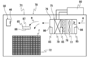
- FIG. 4 is an explanatory diagram showing an application example of the ozone detection device of the present invention to a storage device.
- the storage device 70 includes a fresh product storage 71, in which fresh products f are stored in a stacked basket 72 inside the fresh product storage 71 and stored at a temperature equal to or higher than a chilled state. Inside the fresh product storage 71, there are provided a temperature adjustment unit 75 for maintaining the temperature in the storage at a temperature equal to or higher than a chilled state, and an air flow generation unit 77 for generating an air flow a in the storage.
- the temperature control unit 75 includes an air flow generation unit 77 including a fan, a defrost and temperature control heater 78 inside a casing 76 having an inlet and an outlet for the air flow a, and a refrigerator provided outside the refrigerator.
- a heat exchanger 79 to which a refrigerant is supplied from 80 is provided.
- An air flow path b is formed inside the casing 76, and an air flow a is formed in the air flow path b. The temperature of the air flow a is adjusted by being heated by the heater 78 or cooled by the heat exchanger 79.
- an irradiation unit 85 that irradiates vacuum ultraviolet rays is provided in the casing 76 of the temperature adjustment unit 75 and above the basket 72 in which the fresh product f is stored.
- the irradiating section 85 includes a discharge lamp 87 formed of an excimer lamp or a rare gas fluorescent lamp capable of emitting vacuum ultraviolet light having a single wavelength of less than 200 nm, and the vacuum ultraviolet light from the discharge lamp 87 passes through an ultraviolet irradiation window 86. It is configured to emit light.
- the irradiation unit 85 is controlled by a not-shown intermittent irradiation control unit so as to intermittently irradiate vacuum ultraviolet rays.
- radicals such as ozone and OH radicals are generated around the fresh product f by irradiating the air flow a with vacuum ultraviolet rays from the irradiation unit 85.
- the generated ozone or radicals (hereinafter also referred to as “ozone or the like”) are diffused throughout the perishable goods storage 71 by the air flow a.
- the above-mentioned ozone detection device 50 is provided inside the perishable product storage 71, and the ozone concentration in the perishable product storage 71 is controlled based on the detection signal from the ozone detection device 50. Is done. Specifically, a detection signal from the ozone detection device 50 is input to the intermittent irradiation control unit, and the operation of the discharge lamp 87 in the irradiation unit 85 is controlled based on the detection signal by the intermittent irradiation control unit. The ozone concentration in the storage 71 is adjusted to an appropriate size.
- the position where the ozone detecting device 50 is installed is a position that is hardly affected by, for example, electromagnetic wave noise inevitably generated in the irradiation unit 85.
- ozone detection in the fresh food storage 71 can be performed with high accuracy.
- the ozone detectors 50 are installed at a plurality of locations in the fresh food storage 71. Thereby, even when the ozone concentration in the fresh food storage 71 varies, the operation control of the irradiation unit 85 can be appropriately performed.
- the heater in the ozone sensor is not limited to the configuration according to the above-described embodiment as long as it can heat a member constituting the gas contact surface so that the gas contact surface has a predetermined temperature.
- the heater does not need to be provided on the entire outer surface of the sensor main body except for the gas contact surface, and is provided so as to efficiently heat the members constituting the gas contact surface.
- the ozone detection device of the above-described embodiment can be applied to ozone concentration detection not only in a storage in a perishable storage device but also in a space where ozone concentration management is required.
Landscapes
- Chemical & Material Sciences (AREA)
- Life Sciences & Earth Sciences (AREA)
- Health & Medical Sciences (AREA)
- Biochemistry (AREA)
- Chemical Kinetics & Catalysis (AREA)
- Electrochemistry (AREA)
- Physics & Mathematics (AREA)
- Analytical Chemistry (AREA)
- Molecular Biology (AREA)
- General Health & Medical Sciences (AREA)
- General Physics & Mathematics (AREA)
- Immunology (AREA)
- Pathology (AREA)
- Investigating Or Analyzing Non-Biological Materials By The Use Of Chemical Means (AREA)
- Investigating Or Analyzing Materials By The Use Of Fluid Adsorption Or Reactions (AREA)
- Cold Air Circulating Systems And Constructional Details In Refrigerators (AREA)
Abstract
本発明は、常温高湿環境や、低温高湿環境もしくは極低温環境などの極限環境下においても、安定したオゾン検出動作が可能なオゾンセンサおよびオゾン検出装置を提供することを目的とする。 上記課題は、外部に露出してオゾン含有雰囲気ガスと接触するガス接触面を有するセンサ本体を備えており、当該センサ本体における前記ガス接触面を構成する部材を加熱するヒータを有するオゾンセンサにより解決される。
Description
本発明は、オゾンセンサおよび当該オゾンセンサを備えたオゾン検出装置に関する。
近年、強い酸化力を有するオゾンは、例えば、食品の鮮度を維持したり保存期間を延長したりするためや、食品などの洗浄および漂白、冷蔵庫内などの脱臭などに利用されるようになってきている。
例えば、特許文献1には、紫外線を空気流に照射してオゾンを生成し、生成されたオゾンによって生鮮品の保管、冷蔵又は解凍時の殺菌を行う保管装置が開示されている。
例えば、特許文献1には、紫外線を空気流に照射してオゾンを生成し、生成されたオゾンによって生鮮品の保管、冷蔵又は解凍時の殺菌を行う保管装置が開示されている。
オゾンを利用した殺菌、脱臭処理にあっては、オゾン濃度を必要値まで高めることが必要とされる一方で、濃度によっては人体に対して悪影響を及ぼすとされているため、オゾン濃度の適切な管理が必要とされる。
そこで、上記特許文献1には、生鮮品保管庫の内部にオゾン等の濃度を検出するオゾンセンサが設けられ、オゾンセンサの検出値に基づいて紫外線照射部の動作を制御することが記載されている。また、紫外線照射部は、200nm未満の単一波長の真空紫外線を放射可能なエキシマランプ又は希ガス蛍光ランプで構成されることが記載されている。
そこで、上記特許文献1には、生鮮品保管庫の内部にオゾン等の濃度を検出するオゾンセンサが設けられ、オゾンセンサの検出値に基づいて紫外線照射部の動作を制御することが記載されている。また、紫外線照射部は、200nm未満の単一波長の真空紫外線を放射可能なエキシマランプ又は希ガス蛍光ランプで構成されることが記載されている。
而して、オゾンの濃度測定方法としては、例えば、紫外線吸収法、薄膜半導体法、隔膜ポーラログラフ法および検知管法が知られているが、いずれの測定方法を利用したオゾンセンサであっても、安定したオゾン検出動作を行うためには、オゾン含有雰囲気ガスが接触するガス接触面に結露の発生がない状態とされることが不可欠である。結露がガス接触面に生じた場合には、検出信号の信号レベルが低下し検出精度が低下する。そして、結露が発生した状態のオゾンセンサが例えば低温環境下に置かれると、水分が凍結して霜が発生するため、オゾン検出が困難となる。
しかしながら、結露が生じやすい環境下、具体的には、例えば、常温高湿環境(20~40℃、80%RH以上)、低温高湿環境(0~10度、80%RH以上)もしくは極低温環境(-40~-10℃)などの極限環境下において安定したオゾン検出動作が可能なオゾンセンサは知られていないのが実情である。
しかしながら、結露が生じやすい環境下、具体的には、例えば、常温高湿環境(20~40℃、80%RH以上)、低温高湿環境(0~10度、80%RH以上)もしくは極低温環境(-40~-10℃)などの極限環境下において安定したオゾン検出動作が可能なオゾンセンサは知られていないのが実情である。
また、上記特許文献1のように、オゾンを生成するために紫外線ランプ(エキシマランプ)から照射される紫外線が利用される場合には、ランプ点灯時は高電圧が印加されるため、電磁波ノイズが不可避的に発生する。このため、オゾン濃度センサから出力されるオゾン検出信号が電磁波ノイズによる影響を受けて検出精度が低下するおそれがある、という問題がある。
本発明は、以上のような事情に基づいてなされたものであって、常温高湿環境(20~40℃、80%RH以上)や、低温高湿環境(0~10℃、80%RH以上)もしくは極低温環境(-40~-10℃)などの極限環境下においても、安定したオゾン検出動作が可能なオゾンセンサおよびオゾン検出装置を提供することを目的とする。
本発明のオゾンセンサは、外部に露出してオゾン含有雰囲気ガスと接触するガス接触面を有するセンサ本体を備えており、当該センサ本体における前記ガス接触面を構成する部材を加熱するヒータを有することを特徴とする。
本発明のオゾンセンサにおいては、前記ヒータは、前記ガス接触面を除く前記センサ本体の外面を覆うように設けられていることが好ましい。
また、本発明のオゾンセンサにおいては、前記センサ本体は、軸方向における一端にガス入口が形成された筒状のセンサケースを備えており、
前記ガス接触面を構成する部材が、当該センサケースのガス入口を塞ぐよう設けられたガス透過フィルタであることが好ましい。
前記ガス接触面を構成する部材が、当該センサケースのガス入口を塞ぐよう設けられたガス透過フィルタであることが好ましい。
さらにまた、本発明のオゾンセンサにおいては、前記ヒータは、抵抗発熱線がシート状部材で覆われて構成されており、
前記シート状部材は、前記センサ本体に面する側の内面側部分に対して、前記抵抗発熱線を挟んで反対側に位置される外面側部分の熱伝導特性が低くなるよう構成されることが好ましい。
前記シート状部材は、前記センサ本体に面する側の内面側部分に対して、前記抵抗発熱線を挟んで反対側に位置される外面側部分の熱伝導特性が低くなるよう構成されることが好ましい。
さらにまた、本発明のオゾンセンサにおいては、前記センサケースにおけるガス入口の内面側には、疎水性を有する通気性隔離膜が設けられていることが好ましい。
本発明のオゾン検出装置は、上記のオゾンセンサを備えたオゾン検出装置であって、
開口部を有し、内部に電装部を収容する筐体を備えており、
前記オゾンセンサは、前記ガス接触面が外部に露出された状態で、前記筐体における開口部を塞ぐように設けられていることを特徴とする。
開口部を有し、内部に電装部を収容する筐体を備えており、
前記オゾンセンサは、前記ガス接触面が外部に露出された状態で、前記筐体における開口部を塞ぐように設けられていることを特徴とする。
本発明のオゾン検出装置においては、前記オゾンセンサの前記ガス接触面を除く外面が断熱部材で覆われていることが好ましい。
本発明のオゾンセンサによれば、ガス接触面を構成する部材をヒータによって加熱することにより、ガス接触面に結露が生ずることを確実に防止することができるので、信頼性の高いオゾン検出を行うことができる。
従って、本発明のオゾンセンサは、例えば、常温高湿環境(20~40℃、80%RH以上)や、低温高湿環境(0~10℃、80%RH以上)もしくは極低温環境(-40~-10℃)などの環境下で使用される場合に極めて有用なものとなる。
従って、本発明のオゾンセンサは、例えば、常温高湿環境(20~40℃、80%RH以上)や、低温高湿環境(0~10℃、80%RH以上)もしくは極低温環境(-40~-10℃)などの環境下で使用される場合に極めて有用なものとなる。
ヒータがガス接触面を除くセンサ本体の外面を覆うように設けられた構成とされることにより、高い熱効率を得ることができると共にヒータが外部環境に対する断熱材としての役割も果たすため、ガス接触面を構成する部材を効率よく加熱することができる。
ガス接触面を構成する部材がガス透過フィルタであることにより、結露によりガス透過フィルタ本来の機能が損なわれることを回避することができるため、オゾン含有雰囲気ガスを確実に検出素子に供給することができて信頼性の高いオゾン検出を行うことができる。
抵抗発熱線がシート状部材で覆われてなるヒータにおけるセンサ本体に面する側に位置されるシート状部材の内面側部分に対して、前記抵抗発熱線を挟んで反対側に位置されるシート状部材の外面側部分の熱伝導特性が低くなるよう構成されることにより、断熱性能が高くなることでガス接触面を構成する部材に対して効率よく熱を伝えることができ、しかも、ガス接触面を構成する部材が外部環境による影響を受けて所定温度以下に低下した状態となることを抑制することができる。
センサケースにおけるガス入口の内面側に、疎水性を有する通気性隔離膜が設けられた構成とされることにより、センサ本体内部に対する外部からの水分の侵入を防止することができるため、一層信頼性の高いオゾン検出を行うことができる。
上記のオゾンセンサを備えた本発明のオゾン検出装置によれば、電装部が筐体内に収容されているため、外部環境の影響によってセンシングが阻害されることを確実に回避することができ、信頼性の高いオゾン検出を行うことができる。
オゾンセンサが断熱部材で覆われた構成とされることにより、外部環境の影響によるヒータの加熱効率の低下を抑制することができると共にオゾンセンサにおけるガス接触面の温度低下を抑制することができるため、オゾンセンサにおけるガス接触面に結露が生ずることを確実に防止することができる。
以下、本発明の実施の形態について詳細に説明する。
〔オゾンセンサ〕
本発明のオゾンセンサは、外部に露出してオゾン含有雰囲気ガスと接触するガス接触面を有するセンサ本体を備えており、当該センサ本体における前記ガス接触面を構成する部材を加熱するヒータを有することを特徴とする。
本発明のオゾンセンサは、外部に露出してオゾン含有雰囲気ガスと接触するガス接触面を有するセンサ本体を備えており、当該センサ本体における前記ガス接触面を構成する部材を加熱するヒータを有することを特徴とする。
センサ本体は、紫外線吸収法、薄膜半導体法、隔膜ポーラログラフ法および検知管法のいずれの測定方法を用いたものであってもよい。
本発明のオゾンセンサにおいては、センサ本体としては、例えば全体が略円柱状であって、軸方向における一端にガス接触面を有する構成のものを用いることができる。具体的には例えば、センサ本体は、軸方向における一端にガス入口が形成された筒状のセンサケースと、センサケース内に配置されたオゾン検出素子と、センサケースのガス入口を塞ぐよう設けられたガス透過フィルタとを備えた構成のものを例示することができる。このようなセンサ本体においては、ガス接触面を構成する部材はガス透過フィルタである。
また、センサ本体は、センサケースにおけるガス入口の内面側に、疎水性を有する通気性隔離膜が設けられた構成とされていることが好ましい。このような構成とされることにより、センサ本体内部に対する外部からの水分の侵入を防止することができるため、一層信頼性の高いオゾン検出を行うことができる。
本発明のオゾンセンサにおいては、センサ本体としては、例えば全体が略円柱状であって、軸方向における一端にガス接触面を有する構成のものを用いることができる。具体的には例えば、センサ本体は、軸方向における一端にガス入口が形成された筒状のセンサケースと、センサケース内に配置されたオゾン検出素子と、センサケースのガス入口を塞ぐよう設けられたガス透過フィルタとを備えた構成のものを例示することができる。このようなセンサ本体においては、ガス接触面を構成する部材はガス透過フィルタである。
また、センサ本体は、センサケースにおけるガス入口の内面側に、疎水性を有する通気性隔離膜が設けられた構成とされていることが好ましい。このような構成とされることにより、センサ本体内部に対する外部からの水分の侵入を防止することができるため、一層信頼性の高いオゾン検出を行うことができる。
ヒータは、例えば、ニッケルクロム合金よりなる抵抗発熱線が絶縁性を有するシート状部材で覆われて構成されたものを用いることができる。シート状部材としては、例えばシリコンスポンジシートなどを例示することができる。
本発明のオゾンセンサにおいては、ヒータは、ガス接触面を除くセンサ本体の外面を覆うように設けられていることが好ましい。このような構成とされていることにより、高い熱効率を得ることができると共にヒータが外部環境に対する断熱材としての役割も果たすため、ガス接触面を構成する部材を効率よく加熱することができる。
本発明のオゾンセンサにおいて用いられるヒータの一構成例を図1に示す。
本発明のオゾンセンサにおいては、ヒータは、ガス接触面を除くセンサ本体の外面を覆うように設けられていることが好ましい。このような構成とされていることにより、高い熱効率を得ることができると共にヒータが外部環境に対する断熱材としての役割も果たすため、ガス接触面を構成する部材を効率よく加熱することができる。
本発明のオゾンセンサにおいて用いられるヒータの一構成例を図1に示す。
図1に示すヒータ10は、抵抗発熱線11が一面側シート部材15および他面側シート部材16によって挟み込まれて構成されている。抵抗発熱線11は他面側シート部材16の一面上において所定パターンに配設されている。
ヒータ10は、断熱性能が高くなるように構成されていることが好ましい。具体的には、一面側シート部材15および他面側シート部材16のいずれか一方または両方に断熱特性の高い部材を付加させたり、一面側シート部材15および他面側シート部材16の厚みを調整したりすることによって、ヒータ10の断熱性能を高くすることができる。
ヒータ10は、センサ本体に面する側の内面側部分を構成する一面側シート部材15に対して抵抗発熱線11を挟んでセンサ本体の反対側に位置される外面側部分を構成する他面側シート部材16の熱伝導特性が低くなるよう構成されることが好ましい。このような構成とされることにより、断熱性能が高くなることでガス接触面を構成する部材に対して効率よく熱を伝えることができ、しかも、ガス接触面を構成する部材が外部環境による影響を受けて所定温度以下に低下した状態となることを抑制することができる。
ヒータ10は、断熱性能が高くなるように構成されていることが好ましい。具体的には、一面側シート部材15および他面側シート部材16のいずれか一方または両方に断熱特性の高い部材を付加させたり、一面側シート部材15および他面側シート部材16の厚みを調整したりすることによって、ヒータ10の断熱性能を高くすることができる。
ヒータ10は、センサ本体に面する側の内面側部分を構成する一面側シート部材15に対して抵抗発熱線11を挟んでセンサ本体の反対側に位置される外面側部分を構成する他面側シート部材16の熱伝導特性が低くなるよう構成されることが好ましい。このような構成とされることにより、断熱性能が高くなることでガス接触面を構成する部材に対して効率よく熱を伝えることができ、しかも、ガス接触面を構成する部材が外部環境による影響を受けて所定温度以下に低下した状態となることを抑制することができる。
図2は、本発明のオゾンセンサの一例における構成を概略的に示す断面図である。
このオゾンセンサ20は、例えば隔膜ポーラログラフ法を利用した電気化学式センサであって、作用極31および対極32の両極間に流れる電流の大きさからオゾンガスの定量を行うものである。
このオゾンセンサ20は、軸方向における一端にガス接触面46を有する円柱状のセンサ本体21と、ガス接触面46を除くセンサ本体21の外面を覆うように設けられたヒータ10とにより構成されている。
このオゾンセンサ20は、例えば隔膜ポーラログラフ法を利用した電気化学式センサであって、作用極31および対極32の両極間に流れる電流の大きさからオゾンガスの定量を行うものである。
このオゾンセンサ20は、軸方向における一端にガス接触面46を有する円柱状のセンサ本体21と、ガス接触面46を除くセンサ本体21の外面を覆うように設けられたヒータ10とにより構成されている。
センサ本体21は、一端が開口する有底円筒状のケース本体26と、ケース本体26の開口を塞ぐように設けられた円板状の蓋体27とにより構成されたセンサケース25を備えている。蓋体27には中央部にガス入口28を形成する開口部が形成されている。
センサケース25の内部には、作用極31、対極32および参照極33がそれぞれの間に電解液保持部材36が介在された状態で積層された電極構造体よりなるガス検出素子30が配置されており、作用極31、対極32および参照極33の各々に電気的に接続された電極端子35がセンサケース25の外部に液密に導出されている。
センサケース25の蓋体27には、疎水性を有する通気性隔離膜40がガス入口28を内面側から液密に塞ぐように設けられている。39は、例えばO-リングよりなるシール部材である。
通気性隔離膜40を構成する材質としては、オゾン含有雰囲気ガスを透過させ、水分の侵入および電解液の漏洩を防止することができるものであれば、従来より好適に用いられている材料のいずれのものも用いることができる。
通気性隔離膜40を構成する材質としては、オゾン含有雰囲気ガスを透過させ、水分の侵入および電解液の漏洩を防止することができるものであれば、従来より好適に用いられている材料のいずれのものも用いることができる。
また、センサケース25を構成する蓋体27の外面には、ダストフィルタとして機能するガス透過フィルタ45がガス入口28を外面側から塞ぐように設けられており、ガス透過フィルタ45の外面によってガス接触面46が構成されている。
ヒータ10は、上述のように、抵抗発熱線が絶縁性を有するシート状部材で覆われて構成されたものを用いることができる。
而して、このオゾンセンサ20においては、ガス接触面46の温度が外部環境雰囲気の温度に応じて設定された温度となるように、ヒータ10に対する通電が制御される。
具体的には例えば、オゾンセンサ20のガス接触面46の設定温度は、当該オゾンセンサ20が設置される環境雰囲気の温度よりも少なくとも2~3℃程度以上高い温度とされる。
一方、例えば冷蔵庫内や冷凍庫内などの極限環境雰囲気下で使用される場合においては、扉開閉時に庫内温度が変動することを考慮して、オゾンセンサ20のガス接触面46の設定温度は、冷蔵庫内温度よりも例えば5~6℃程度高い温度とされる。
ガス接触面46の温度が必要以上に高い温度となる条件でヒータ10が駆動される場合には、消費電力が大きくなり、しかも外部環境との温度差が大きくなることで熱が拡散するため、熱効率が悪化することとなる。
具体的には例えば、オゾンセンサ20のガス接触面46の設定温度は、当該オゾンセンサ20が設置される環境雰囲気の温度よりも少なくとも2~3℃程度以上高い温度とされる。
一方、例えば冷蔵庫内や冷凍庫内などの極限環境雰囲気下で使用される場合においては、扉開閉時に庫内温度が変動することを考慮して、オゾンセンサ20のガス接触面46の設定温度は、冷蔵庫内温度よりも例えば5~6℃程度高い温度とされる。
ガス接触面46の温度が必要以上に高い温度となる条件でヒータ10が駆動される場合には、消費電力が大きくなり、しかも外部環境との温度差が大きくなることで熱が拡散するため、熱効率が悪化することとなる。
ヒータ10に対する通電は、オゾンセンサ20のガス接触面46の温度が一定温度に維持されるように制御される必要はなく、外部環境雰囲気の温度変化に応じて可変させてもよい。すなわち、外部環境雰囲気の温度を適宜の温度検出手段で検出し、その検出結果に基づいてヒータ10に対する通電をフィードバック制御するように構成されていてもよい。このような構成のものにおいては、オゾンセンサ20が設置される環境雰囲気の温度を細かく変化させる場合や、オゾンセンサ20を例えば冷蔵庫内から外部に持ち出す場合などにおいても、ガス接触面46に結露が生ずることを確実に防止することができる。
このオゾンセンサ20においては、オゾン含有雰囲気ガスが導入されると、作用極31においては下記式(a)で示される還元反応が生じ、対極32においては下記式(b)で示される酸化反応が生じ、これにより、作用極31および対極32の両極間に電流が流れる。
式(a) O3 +2e- +2H+ →O2 +H2 O
式(b) H2 O→1/2O2 +2e- +2H+
そして、作用極31および対極32の両極間に流れる電流が検出されることにより、当該電流の大きさに応じたオゾン濃度が検出される。
式(a) O3 +2e- +2H+ →O2 +H2 O
式(b) H2 O→1/2O2 +2e- +2H+
そして、作用極31および対極32の両極間に流れる電流が検出されることにより、当該電流の大きさに応じたオゾン濃度が検出される。
而して、上記構成のオゾンセンサ20によれば、ガス接触面46を構成する部材であるガス透過フィルタ45をヒータ10によって加熱することによりガス接触面46に結露が生ずることを確実に防止することができる。このため、結露によりガス透過フィルタ45本来の機能が損なわれることを回避することができる結果、オゾン含有雰囲気ガスを確実に検出素子に供給することができて信頼性の高いオゾン検出を行うことができる。
そして、上記構成のオゾンセンサ20は、例えば、常温高湿環境(20~40℃、80%RH以上)や、低温高湿環境(0~10℃、80%RH以上)もしくは極低温環境(-40~-10℃)などの環境下で使用される場合に極めて有用なものとなる。
そして、上記構成のオゾンセンサ20は、例えば、常温高湿環境(20~40℃、80%RH以上)や、低温高湿環境(0~10℃、80%RH以上)もしくは極低温環境(-40~-10℃)などの環境下で使用される場合に極めて有用なものとなる。
〔オゾン検出装置〕
図3は、本発明のオゾン検出装置の一構成例を概略的に示す断面図である。
このオゾン検出装置50は、開口部52を有する筐体51を備えており、上記のオゾンセンサ20が、ガス接触面46が外部に露出された状態で、筐体51における開口部52を塞ぐように設けられている。筐体51の内部には、オゾンセンサ20の電極端子35が電気的に接続された電装部55が収容されている。筐体51を構成する材料としては、例えばステンレス鋼を用いることができる。
図3は、本発明のオゾン検出装置の一構成例を概略的に示す断面図である。
このオゾン検出装置50は、開口部52を有する筐体51を備えており、上記のオゾンセンサ20が、ガス接触面46が外部に露出された状態で、筐体51における開口部52を塞ぐように設けられている。筐体51の内部には、オゾンセンサ20の電極端子35が電気的に接続された電装部55が収容されている。筐体51を構成する材料としては、例えばステンレス鋼を用いることができる。
このオゾン検出装置は、上述したように、例えば、常温高湿環境(20~40℃、80%RH以上)や、低温高湿環境(0~10℃、80%RH以上)もしくは極低温環境(-40~-10℃)などの極限環境下で使用される場合であっても、オゾンセンサ20におけるガス接触面46に結露が生ずることを確実に防止するために、オゾンセンサ20のガス接触面46を除く外面が断熱部材60で覆われた構成とされることが好ましい。
なお、上述したように、ヒータ10自体が断熱性能が高められた構成とされている場合には、断熱部材60を有さない構成とされていてもよい。
なお、上述したように、ヒータ10自体が断熱性能が高められた構成とされている場合には、断熱部材60を有さない構成とされていてもよい。
さらにまた、オゾン検出装置50が紫外線ランプ(エキシマランプ)から照射される紫外線を利用してオゾンを生成するオゾン発生器と同一の環境雰囲気下で使用される場合には、外部からの電磁波ノイズによってセンシングが阻害されないように、電磁波遮蔽部材(図示せず)が、オゾンセンサ20の外面におけるガス接触面46を除く領域を覆う状態で設けられた構成とされることが好ましい。なお、断熱部材60が電磁波遮蔽機能を有するものとして構成されていてもよい。
而して、上記のオゾン検出装置50によれば、電装部55が筐体51内に収容されているため、外部環境の影響によってセンシングが阻害されることを確実に回避することができ、信頼性の高いオゾン検出を行うことができる。
また、オゾンセンサ20が断熱部材60で覆われた構成とされることにより、外部環境の影響によるヒータ10の加熱効率の低下を抑制することができると共にオゾンセンサ20におけるガス接触面46の温度低下を抑制することができるため、オゾンセンサ20におけるガス接触面46に結露が生ずることを確実に防止することができる。
また、オゾンセンサ20が断熱部材60で覆われた構成とされることにより、外部環境の影響によるヒータ10の加熱効率の低下を抑制することができると共にオゾンセンサ20におけるガス接触面46の温度低下を抑制することができるため、オゾンセンサ20におけるガス接触面46に結露が生ずることを確実に防止することができる。
以下、本発明のオゾン検出装置を用いた生鮮品の保管装置への適用例について説明する。
図4は、本発明のオゾン検出装置の保管装置への適用例を示す説明図である。
この保管装置70は、生鮮品保管庫71を備え、生鮮品保管庫71の内部で生鮮品fが段積みされたかご72に収納されてチルド状態以上の温度で保管される。生鮮品保管庫71の内部には、庫内温度をチルド状態以上の温度に保持する温度調整部75と、庫内に空気流aを発生させる空気流発生部77が設けられる。
図4は、本発明のオゾン検出装置の保管装置への適用例を示す説明図である。
この保管装置70は、生鮮品保管庫71を備え、生鮮品保管庫71の内部で生鮮品fが段積みされたかご72に収納されてチルド状態以上の温度で保管される。生鮮品保管庫71の内部には、庫内温度をチルド状態以上の温度に保持する温度調整部75と、庫内に空気流aを発生させる空気流発生部77が設けられる。
温度調整部75は、空気流aの入口及び出口を有するケーシング76の内部に、ファンで構成された空気流発生部77、デフロスト及び温度調整用のヒータ78、及び庫外に設けられた冷凍機80から冷媒が供給される熱交換器79を有する。ケーシング76の内部に空気流路bが形成され、空気流路bに空気流aが形成される。空気流aはヒータ78によって加温され、あるいは熱交換器79によって冷却されることで、温度調整される。
この保管装置70においては、温度調整部75におけるケーシング76内および生鮮品fが収納されたかご72の上方位置に、真空紫外線を照射する照射部85が設けられている。
照射部85は、200nm未満の単一波長の真空紫外線を放射可能なエキシマランプ又は希ガス蛍光ランプよりなる放電ランプ87を備えており、放電ランプ87からの真空紫外線が紫外線照射窓86を介して出射するように構成される。
照射部85は、図示しない断続照射制御部によって真空紫外線を断続的に照射するように制御される。
照射部85は、200nm未満の単一波長の真空紫外線を放射可能なエキシマランプ又は希ガス蛍光ランプよりなる放電ランプ87を備えており、放電ランプ87からの真空紫外線が紫外線照射窓86を介して出射するように構成される。
照射部85は、図示しない断続照射制御部によって真空紫外線を断続的に照射するように制御される。
この保管装置70においては、照射部85から空気流aに真空紫外線を照射することにより、生鮮品fの周囲にオゾンやOHラジカルなどのラジカルが生成される。生成したオゾン又はラジカル(以下「オゾン等」とも言う。)は空気流aにより生鮮品保管庫71の内部全域に拡散する。
而して、この保管装置70においては、上記のオゾン検出装置50が生鮮品保管庫71の内部に設けられ、オゾン検出装置50による検出信号に基づいて生鮮品保管庫71内のオゾン濃度が管理される。具体的には、オゾン検出装置50による検出信号は断続照射制御部に入力され、断続照射制御部によって、照射部85における放電ランプ87の動作が検出信号に基づいて制御されることにより、生鮮品保管庫71内のオゾン濃度が適正な大きさに調整される。
オゾン検出装置50が設置される位置は、例えば照射部85において不可避的に発生する電磁波ノイズによる影響を受けにくい位置であることが好ましい。これにより、生鮮品保管庫71内のオゾン検出を高い精度で行うことができる。
また、オゾン検出装置50は、生鮮品保管庫71内における複数個所に設置されることが好ましい。これにより、生鮮品保管庫71内のオゾン濃度にバラツキが生じている場合であっても、照射部85の動作制御を適正に行うことができる。
また、オゾン検出装置50は、生鮮品保管庫71内における複数個所に設置されることが好ましい。これにより、生鮮品保管庫71内のオゾン濃度にバラツキが生じている場合であっても、照射部85の動作制御を適正に行うことができる。
以上、本発明の実施形態について説明したが、本発明は上記の実施形態に限定されるものではなく、種々の変更を加えることができる。
例えば、オゾンセンサにおけるヒータは、ガス接触面が所定温度となるようにガス接触面を構成する部材を加熱することのできるものであれば、上記実施形態に係る構成のものに限定されるものではなく、種々の構成のものを用いることができる。また、ヒータは、センサ本体のガス接触面を除く外面全体に設けられた構成とされている必要はなく、ガス接触面を構成する部材を効率よく加熱することができるように設けられていればよい。
また、上述した実施形態のオゾン検出装置は、生鮮品の保管装置における保管庫だけでなく、オゾン濃度の管理が必要とされる空間におけるオゾン濃度検出に適用することができる。
例えば、オゾンセンサにおけるヒータは、ガス接触面が所定温度となるようにガス接触面を構成する部材を加熱することのできるものであれば、上記実施形態に係る構成のものに限定されるものではなく、種々の構成のものを用いることができる。また、ヒータは、センサ本体のガス接触面を除く外面全体に設けられた構成とされている必要はなく、ガス接触面を構成する部材を効率よく加熱することができるように設けられていればよい。
また、上述した実施形態のオゾン検出装置は、生鮮品の保管装置における保管庫だけでなく、オゾン濃度の管理が必要とされる空間におけるオゾン濃度検出に適用することができる。
10 ヒータ
11 抵抗発熱線
15 一面側シート部材
16 他面側シート部材
20 オゾンセンサ
21 センサ本体
25 センサケース
26 ケース本体
27 蓋体
28 ガス入口
30 ガス検出素子
31 作用極
32 対極
33 参照極
35 電極端子
36 電解液保持部材
39 シール部材
40 通気性隔離膜
45 ガス透過フィルタ
46 ガス接触面
50 オゾン検出装置
51 筐体
52 開口部
55 電装部
60 断熱部材
70 保管装置
71 生鮮品保管庫
72 かご
75 温度調整部
76 ケーシング
77 空気流発生部
78 ヒータ
79 熱交換器
80 冷凍機
85 照射部
86 紫外線照射窓
87 放電ランプ
a 空気流
b 空気流路
f 生鮮品
11 抵抗発熱線
15 一面側シート部材
16 他面側シート部材
20 オゾンセンサ
21 センサ本体
25 センサケース
26 ケース本体
27 蓋体
28 ガス入口
30 ガス検出素子
31 作用極
32 対極
33 参照極
35 電極端子
36 電解液保持部材
39 シール部材
40 通気性隔離膜
45 ガス透過フィルタ
46 ガス接触面
50 オゾン検出装置
51 筐体
52 開口部
55 電装部
60 断熱部材
70 保管装置
71 生鮮品保管庫
72 かご
75 温度調整部
76 ケーシング
77 空気流発生部
78 ヒータ
79 熱交換器
80 冷凍機
85 照射部
86 紫外線照射窓
87 放電ランプ
a 空気流
b 空気流路
f 生鮮品
Claims (7)
- 外部に露出してオゾン含有雰囲気ガスと接触するガス接触面を有するセンサ本体を備えており、当該センサ本体における前記ガス接触面を構成する部材を加熱するヒータを有することを特徴とするオゾンセンサ。
- 前記ヒータは、前記ガス接触面を除く前記センサ本体の外面を覆うように設けられていることを特徴とする請求項1に記載のオゾンセンサ。
- 前記センサ本体は、軸方向における一端にガス入口が形成された筒状のセンサケースを備えており、
前記ガス接触面を構成する部材が、当該センサケースのガス入口を塞ぐよう設けられたガス透過フィルタであることを特徴とする請求項1または請求項2に記載のオゾンセンサ。 - 前記ヒータは、抵抗発熱線がシート状部材で覆われて構成されており、
前記シート状部材は、前記センサ本体に面する側の一面側部分に対して、前記抵抗発熱線を挟んで反対側に位置される他面側部分の熱伝導特性が低くなるよう構成されることを特徴とする請求項2または請求項3に記載のオゾンセンサ。 - 前記センサケースにおけるガス入口の内面側には、疎水性を有する通気性隔離膜が設けられていることを特徴とする請求項3または請求項4に記載のオゾンセンサ。
- 請求項1乃至請求項5のいずれかに記載のオゾンセンサを備えたオゾン検出装置であって、
開口部を有し、内部に電装部を収容する筐体を備えており、
前記オゾンセンサは、前記ガス接触面が外部に露出された状態で、前記筐体における開口部を塞ぐように設けられていることを特徴とするオゾン検出装置。 - 前記オゾンセンサの前記ガス接触面を除く外面が断熱部材で覆われていることを特徴とする請求項6に記載のオゾン検出装置。
Applications Claiming Priority (2)
| Application Number | Priority Date | Filing Date | Title |
|---|---|---|---|
| JP2018140872A JP6673408B2 (ja) | 2018-07-27 | 2018-07-27 | オゾンセンサおよびオゾン検出装置 |
| JP2018-140872 | 2018-07-27 |
Publications (1)
| Publication Number | Publication Date |
|---|---|
| WO2020021835A1 true WO2020021835A1 (ja) | 2020-01-30 |
Family
ID=69182200
Family Applications (1)
| Application Number | Title | Priority Date | Filing Date |
|---|---|---|---|
| PCT/JP2019/020373 Ceased WO2020021835A1 (ja) | 2018-07-27 | 2019-05-23 | オゾンセンサおよびオゾン検出装置 |
Country Status (3)
| Country | Link |
|---|---|
| JP (1) | JP6673408B2 (ja) |
| TW (1) | TW202007960A (ja) |
| WO (1) | WO2020021835A1 (ja) |
Families Citing this family (4)
| Publication number | Priority date | Publication date | Assignee | Title |
|---|---|---|---|---|
| JP7022865B1 (ja) * | 2021-03-08 | 2022-02-18 | 日本特殊陶業株式会社 | 電気化学式ガスセンサ、オゾン発生器、及び加湿器 |
| WO2022191163A1 (ja) | 2021-03-08 | 2022-09-15 | 日本特殊陶業株式会社 | 電気化学式ガスセンサ、オゾン発生器、及び加湿器 |
| JP7209061B1 (ja) * | 2021-09-07 | 2023-01-19 | 日本特殊陶業株式会社 | オゾン発生器 |
| JP7340180B2 (ja) * | 2021-05-31 | 2023-09-07 | 独立行政法人国立病院機構 | オゾン検知システム及びオゾン発生器 |
Citations (6)
| Publication number | Priority date | Publication date | Assignee | Title |
|---|---|---|---|---|
| US4885929A (en) * | 1987-10-08 | 1989-12-12 | New Cosmos Electric Co. Ltd. | Ozone gas sensor and ozone gas detecting device having ozone gas sensor |
| JPH1019770A (ja) * | 1996-07-08 | 1998-01-23 | Ebara Jitsugyo Kk | ガス濃度測定装置 |
| JP2001324463A (ja) * | 2000-05-12 | 2001-11-22 | Hioki Ee Corp | ガス濃度検出センサおよびガス濃度測定装置 |
| JP2002518673A (ja) * | 1998-06-12 | 2002-06-25 | グリム・エア・エ・デ・エス・ア・エア・エル | 1つまたはいくつかの汚染ガスのための検出器およびその使用方法 |
| JP2004205423A (ja) * | 2002-12-26 | 2004-07-22 | Riken Keiki Co Ltd | 定電位電解型ガスセンサー |
| JP2004219077A (ja) * | 2003-01-09 | 2004-08-05 | Matsushita Electric Ind Co Ltd | ガスセンサ |
-
2018
- 2018-07-27 JP JP2018140872A patent/JP6673408B2/ja not_active Expired - Fee Related
-
2019
- 2019-05-23 WO PCT/JP2019/020373 patent/WO2020021835A1/ja not_active Ceased
- 2019-05-27 TW TW108118178A patent/TW202007960A/zh unknown
Patent Citations (6)
| Publication number | Priority date | Publication date | Assignee | Title |
|---|---|---|---|---|
| US4885929A (en) * | 1987-10-08 | 1989-12-12 | New Cosmos Electric Co. Ltd. | Ozone gas sensor and ozone gas detecting device having ozone gas sensor |
| JPH1019770A (ja) * | 1996-07-08 | 1998-01-23 | Ebara Jitsugyo Kk | ガス濃度測定装置 |
| JP2002518673A (ja) * | 1998-06-12 | 2002-06-25 | グリム・エア・エ・デ・エス・ア・エア・エル | 1つまたはいくつかの汚染ガスのための検出器およびその使用方法 |
| JP2001324463A (ja) * | 2000-05-12 | 2001-11-22 | Hioki Ee Corp | ガス濃度検出センサおよびガス濃度測定装置 |
| JP2004205423A (ja) * | 2002-12-26 | 2004-07-22 | Riken Keiki Co Ltd | 定電位電解型ガスセンサー |
| JP2004219077A (ja) * | 2003-01-09 | 2004-08-05 | Matsushita Electric Ind Co Ltd | ガスセンサ |
Also Published As
| Publication number | Publication date |
|---|---|
| JP2020016593A (ja) | 2020-01-30 |
| TW202007960A (zh) | 2020-02-16 |
| JP6673408B2 (ja) | 2020-03-25 |
Similar Documents
| Publication | Publication Date | Title |
|---|---|---|
| JP6673408B2 (ja) | オゾンセンサおよびオゾン検出装置 | |
| JP5736455B2 (ja) | センサユニット、及びセンサユニットを用いた恒温装置 | |
| CN114796539B (zh) | 带有用于监视容器内的环境的电池供电的传感器模块的消毒容器 | |
| AU2015293969B2 (en) | UVC decontamination and detoxification device | |
| US20060226787A1 (en) | Electrostatic fluid accelerator for and method of controlling a fluid flow | |
| US20100167383A1 (en) | Culture apparatus | |
| Jeng et al. | A dynamic equilibrium method for the SnO2-based ozone sensors using UV-LED continuous irradiation | |
| CN114585913A (zh) | 气体检测装置、气体检测方法及包括气体检测装置的装置 | |
| TW201418651A (zh) | 食品保存庫 | |
| WO2001026697A1 (fr) | Sterilisateur au formaldehyde gazeux | |
| JP2007212459A (ja) | 放射源及び光センサ装置 | |
| JPWO2020166429A1 (ja) | ガス検出装置及びガス検出方法 | |
| JP2001108356A (ja) | 冷蔵庫 | |
| US11137363B2 (en) | Composite sensor for sensing gas and dust by using single heat source | |
| JP5341434B2 (ja) | 培養装置 | |
| JP2003075383A (ja) | 青果物鮮度管理装置 | |
| JPH0810213B2 (ja) | 炭酸ガスセンサ | |
| EP4276075A1 (en) | Purification apparatus and control method thereof | |
| EP3671194B1 (en) | Sensor operable to measure ozone concentration and a method for using a sensor | |
| JP2002365264A (ja) | イオン化式ガス感知器 | |
| CN101208265A (zh) | 使用异极像结晶的臭氧生成方法和装置 | |
| JP2006269596A (ja) | フラッシュランプ発光装置 | |
| CN222938077U (zh) | 制冷设备 | |
| CN118111188A (zh) | 冰箱及其杀菌除味控制方法 | |
| KR20050034451A (ko) | 냉장고의 냄새감지장치 |
Legal Events
| Date | Code | Title | Description |
|---|---|---|---|
| 121 | Ep: the epo has been informed by wipo that ep was designated in this application |
Ref document number: 19842072 Country of ref document: EP Kind code of ref document: A1 |
|
| NENP | Non-entry into the national phase |
Ref country code: DE |
|
| 122 | Ep: pct application non-entry in european phase |
Ref document number: 19842072 Country of ref document: EP Kind code of ref document: A1 |