WO2020021777A1 - ヒートシンク及び溝入れ加工方法 - Google Patents
ヒートシンク及び溝入れ加工方法 Download PDFInfo
- Publication number
- WO2020021777A1 WO2020021777A1 PCT/JP2019/015258 JP2019015258W WO2020021777A1 WO 2020021777 A1 WO2020021777 A1 WO 2020021777A1 JP 2019015258 W JP2019015258 W JP 2019015258W WO 2020021777 A1 WO2020021777 A1 WO 2020021777A1
- Authority
- WO
- WIPO (PCT)
- Prior art keywords
- fins
- cutting
- cut
- groove
- cutter
- Prior art date
- Legal status (The legal status is an assumption and is not a legal conclusion. Google has not performed a legal analysis and makes no representation as to the accuracy of the status listed.)
- Ceased
Links
Images



Classifications
-
- B—PERFORMING OPERATIONS; TRANSPORTING
- B23—MACHINE TOOLS; METAL-WORKING NOT OTHERWISE PROVIDED FOR
- B23D—PLANING; SLOTTING; SHEARING; BROACHING; SAWING; FILING; SCRAPING; LIKE OPERATIONS FOR WORKING METAL BY REMOVING MATERIAL, NOT OTHERWISE PROVIDED FOR
- B23D3/00—Planing or slotting machines cutting by relative movement of the tool and workpiece in a vertical or inclined straight line
- B23D3/02—Planing or slotting machines cutting by relative movement of the tool and workpiece in a vertical or inclined straight line for cutting grooves
-
- H—ELECTRICITY
- H05—ELECTRIC TECHNIQUES NOT OTHERWISE PROVIDED FOR
- H05K—PRINTED CIRCUITS; CASINGS OR CONSTRUCTIONAL DETAILS OF ELECTRIC APPARATUS; MANUFACTURE OF ASSEMBLAGES OF ELECTRICAL COMPONENTS
- H05K7/00—Constructional details common to different types of electric apparatus
- H05K7/20—Modifications to facilitate cooling, ventilating, or heating
-
- H—ELECTRICITY
- H10—SEMICONDUCTOR DEVICES; ELECTRIC SOLID-STATE DEVICES NOT OTHERWISE PROVIDED FOR
- H10W—GENERIC PACKAGES, INTERCONNECTIONS, CONNECTORS OR OTHER CONSTRUCTIONAL DETAILS OF DEVICES COVERED BY CLASS H10
- H10W40/00—Arrangements for thermal protection or thermal control
- H10W40/10—Arrangements for heating
Definitions
- the present invention relates to a heat sink and a grooving method.
- the heat sink includes, for example, a base member made of a metal member, and plate-like fins arranged on the surface of the base member at substantially equal intervals. Since a groove (flow path) is formed between adjacent fins, a semiconductor device or the like disposed on the base member can be suitably cooled by passing a fluid such as air through the groove.
- Patent Document 1 As a conventional heat sink manufacturing method (grooving method), for example, in Patent Document 1, a metal rectangular parallelepiped cut block is cut by a multi-cutter equipped with a disk-shaped cutter, and a plurality of plate-like fins are formed. It is described to form.
- the fin of the conventional heat sink has a rectangular plate shape in plan view. With such fins, the cross-sectional area of the groove between adjacent fins is constant, so that there is a problem that the heat exchange efficiency becomes lower toward the downstream side of the groove.
- an object of the present invention is to provide a heat sink capable of improving heat exchange efficiency.
- Another object of the present invention is to provide a grooving method capable of easily manufacturing, for example, a heat sink having high heat exchange efficiency.
- the present invention is a heat sink including a base member and a plurality of fins disposed perpendicular to the base member, wherein the fin has a trapezoidal shape in plan view.
- the plurality of flow paths formed between the adjacent fins have a trapezoidal shape in a plan view opposite to the fins.
- the cross-sectional area of the flow path gradually decreases toward the downstream side of the flow path, but the cross-sectional area of the fin adjacent to the flow path gradually increases.
- the heat exchange efficiency can be increased even on the downstream side of the flow path.
- the present invention is a multi-cutter in which a plurality of disc-shaped cutters are stacked on a metal member to be cut having a block to be cut having a rectangular parallelepiped and a base member arranged on the bottom surface of the block to be cut.
- a multi-cutter is inserted into the block to be cut at a predetermined cutting angle, and is moved between opposing ridge lines of the block to be cut.
- a first cutting step of forming a first groove in the block the multi-cutter is inserted into the cut block at a predetermined cutting angle, and moved between opposing ridge lines of the cut block to the cut block.
- the plurality of cut fins In the second notch step of forming the second groove, and in the first notch step and the second notch step, the plurality of cut fins have a trapezoidal shape in plan view. As well as, and a plurality of flow paths formed by said first groove and said second groove and said fin sets each said cutting angle so that the plan view trapezoidal opposite.
- the thickness of the disc-shaped cutter is t
- the distance between opposing ridge lines of the block to be cut is L
- the cutting angle with respect to a reference line orthogonal to the ridge line is ⁇
- the cutting angle with respect to a reference line orthogonal to the ridge line is ⁇
- the angle is set so as to satisfy 0 ⁇ 2Ltan ⁇ ⁇ t.
- the heat exchange efficiency can be improved.
- a heat sink having high heat exchange efficiency can be easily manufactured.
- the grooving method according to the present invention involves cutting a metal member using a multi-cutter in which a plurality of disk-shaped cutters are stacked to form a groove.
- the grooving method can be adopted when manufacturing various products.
- a case where a heat sink is manufactured by cutting a metal member to be cut will be described as an example.
- a heat sink 1 manufactured by the grooving method according to the present embodiment includes a base member 2, a plurality of fins 3 arranged side by side at substantially equal intervals on a surface 2 a of the base member 2, Having.
- a groove 4 is formed between the adjacent fins 3.
- the groove 4 is a portion that becomes a flow path through which the fluid flows. The fluid flows, for example, from the wide side of the groove 4 to the narrow side.
- the base member 2 is a metal member formed of a rectangular parallelepiped, and is, for example, a member having a heating element disposed on the back surface side and transmitting heat generated by the heating element to the fin 3 side.
- the fins 3 are metal members having a trapezoidal shape in a plan view and exhibiting a plate shape, and a plurality of fins 3 are arranged on the surface 2 a of the base member 2 at substantially equal intervals.
- the number of the fins 3 is not limited.
- a trapezoidal groove 4 that is continuous in the longitudinal direction of the fin 3 and formed in a plan view is formed between the adjacent fins 3.
- the trapezoidal groove 4 is arranged adjacent to the trapezoidal fin 3 so that the direction is opposite.
- a fluid air, water, or the like
- the height and thickness of the fins 3, the number of the fins 3, the width and the number of the grooves 4, and the like are set as appropriate according to the intended use of the heat sink 1.
- the base member 2 and the fins 3 are integral in this embodiment, and are formed of, for example, an aluminum alloy.
- the materials of the base member 2 and the fins 3 are not limited to these, and may be aluminum, copper, a copper alloy, titanium, a titanium alloy, magnesium, a magnesium alloy, or the like.
- the base member 2 and the fins 3 may be different materials.
- the multi-cutter M is a cutting tool including a shaft portion M1 and a plurality of disk-shaped cutters M2, as shown in FIG.
- the shaft portion M1 is a shaft member serving as a rotation shaft.
- the thickness t of the disk-shaped cutter M2 determines the width of a first groove 41 and a second groove 42 described later.
- the interval g between the adjacent disk-shaped cutters M2 determines an uncut area (fin 3).
- the metal member to be cut 20 which is a member to be cut, will be described.
- the metal member to be cut 20 includes a base member 2 having a rectangular parallelepiped shape, and a block 21 to be cut which is formed smaller than the base member 2 and has a rectangular parallelepiped shape.
- a pair of sides facing in the lateral direction of the metal member 20 to be cut are defined as a first ridgeline 31 and a second ridgeline 32.
- the metal member to be cut 20 is formed integrally, but may be formed by joining a plurality of members.
- the shape of the metal member 20 to be cut may be determined as appropriate according to the intended use of the heat sink 1.
- the grooving method includes a preparation step, a first cutting step, a second cutting step, and a burr cutting step.
- the preparation step is a step of preparing the metal member to be cut 20 and the multi-cutter M.
- the metal member to be cut 20 is immovably fixed to a table (not shown).
- the first cutting step is a step of forming the first groove 41 in the cut block 21 by moving the multi-cutter M obtained by rotating the disk-shaped cutter M2, as shown in FIGS.
- the multi-cutter M is moved and cut while the shaft portion M1 of the multi-cutter M is inclined with respect to the first ridgeline 31. More specifically, the angle (cutting angle) between the reference line P orthogonal to the first ridgeline 31 and the virtual line Q passing through the plane of the disk-shaped cutter M2 is set to be ⁇ . Then, while maintaining the cutting angle ⁇ , the multi-cutter M is moved from the first ridgeline 31 to the second ridgeline 32.
- first groove 41A By moving the multi-cutter M, a plurality of first grooves 41 are formed at equal intervals in the block 21 to be cut.
- first groove 41A among the first grooves 41 in FIG. 4, the leftmost first groove 41 is referred to as a "first groove 41A”.
- the disc-shaped cutter M2 obtained by cutting the first groove 41A at the left end is referred to as "disc-shaped cutter M2A”.
- the disk-shaped cutter M2A is the second disk-shaped cutter M2 from the left.
- the second cutting step is a step of moving the multi-cutter M rotating the disk-shaped cutter M2 to form the second groove 42 in the cut block 21 as shown in FIG.
- the multi-cutter M is moved while the shaft portion M1 of the multi-cutter M is inclined with respect to the first ridgeline 31.
- the multi-cutter M is inclined to the side opposite to the first cutting step.
- the angle (cutting angle) between the reference line P orthogonal to the first ridgeline 31 and the virtual line Q passing through the plane of the disk-shaped cutter M2 is set to be - ⁇ . Then, the multi-cutter M is moved from the first ridgeline 31 to the second ridgeline 32 and cut so that the left end M2Aa of the disc-shaped cutter M2A on the traveling direction side passes through the left entrance 41Aa of the first groove 41.
- the contact position of the disc-shaped cutter M2 in the first cutting step and the second cutting step is set to be the same.
- the trapezoidal fins 3 are cut out at equal intervals in plan view.
- the first groove 41 and the second groove 42 form the trapezoidal groove 4 in plan view (see FIG. 1).
- the trapezoidal groove 4 is adjacent to the trapezoidal fin 3 in an opposite direction.
- the cutting depth in the first cutting step and the second cutting step may be set as appropriate.
- the height of the fin 3 (the block 21 to be cut) and the cutting depth are the same, but for example, the cutting depth may be smaller than the height of the fin 3 (the block 21 to be cut).
- the setting of the cutting angle ⁇ will be described. After performing the first cutting step and the second cutting step, the trapezoidal fin 3 and the trapezoidal groove 4 are formed, and an uncut region having the same height as the fin 3 remains in the groove 4. It is preferable to set appropriately so as not to do so.
- the thickness of the disk-shaped cutter M2 of the multi-cutter M be thickness t.
- the gap between the disk-shaped cutters M2 is defined as a gap g.
- the distance between the ridge lines from the first ridge line 31 to the second ridge line 32 is defined as a distance L.
- the deburring step is a step of cutting off burrs generated in the first cutting step and the second cutting step.
- the cross-sectional area gradually decreases from the upstream side to the downstream side of the groove 4 (flow path), but the cross-sectional area of the fins 3 adjacent to the flow path becomes smaller. It grows gradually. Thus, the heat exchange efficiency can be increased even on the downstream side of the flow path.
- the multi-cutter M since the multi-cutter M only needs to be moved twice, a heat sink having high heat exchange efficiency can be easily manufactured. Further, by performing the deburring step, the heat sink can be finished finely.
- the first cutting step may cut from the first ridgeline 31, and the second cutting step may cut from the second ridgeline 32.
- the groove may be formed by cutting the uncut area.
Landscapes
- Engineering & Computer Science (AREA)
- Mechanical Engineering (AREA)
- Physics & Mathematics (AREA)
- Thermal Sciences (AREA)
- Microelectronics & Electronic Packaging (AREA)
- Milling Processes (AREA)
- Cooling Or The Like Of Electrical Apparatus (AREA)
- Cooling Or The Like Of Semiconductors Or Solid State Devices (AREA)
- Milling, Broaching, Filing, Reaming, And Others (AREA)
Abstract
ベース部材(2)と、ベース部材(2)に対して垂直に配設された複数のフィン(3)とを備えたヒートシンク(1)であって、フィン(3)は、平面視台形を呈し、隣り合うフィン(3,3)の間に形成される複数の溝(4)はフィン(3)とは反対向きの平面視台形を呈することを特徴とする。溝(4)の下流側に向かうにつれて溝(4)の断面積が徐々に小さくなるが、溝(4)に隣接するフィン(3)の断面積は徐々に大きくなる。これにより、溝(4)の下流側であっても熱交換効率を高めることができる。
Description
本発明は、ヒートシンク及び溝入れ加工方法に関する。
半導体デバイス等は、動作時の発熱量が大きいため、例えばヒートシンクを介して放熱することにより温度の上昇を抑制している。当該ヒートシンクは、例えば、金属部材からなるベース部材と、当該ベース部材の表面に略等間隔で並設された板状のフィンとで構成されている。隣り合うフィンの間には溝(流路)が形成されているため、当該溝に空気などの流体が通ることにより、ベース部材に配置された半導体デバイス等を好適に冷却することができる。
従来のヒートシンクの製造方法(溝入れ加工方法)として、例えば、特許文献1には、円盤型カッターを備えたマルチカッターで金属製の直方体の被切削ブロックを切削し、板状の複数のフィンを形成することが記載されている。
従来のヒートシンクのフィンは、平面視矩形の板状を呈している。このフィンであると、隣り合うフィン間の溝の断面積は一定であるため、溝の下流側に向かうにつれて熱交換効率が悪くなるという問題があった。
このような観点から、本発明は、熱交換効率を高めることができるヒートシンクを提供することを課題とする。また、本発明は、例えば、熱交換効率の高いヒートシンクを容易に製造することができる溝入れ加工方法を提供することを課題とする。
このような課題を解決するために本発明は、ベース部材と、前記ベース部材に対して垂直に配設された複数のフィンとを備えたヒートシンクであって、前記フィンは、平面視台形を呈し、隣り合う前記フィンの間に形成される複数の流路は前記フィンとは反対向きの平面視台形を呈することを特徴とする。
かかる構成であると、流路の下流側に向かうにつれて流路の断面積が徐々に小さくなるが、流路に隣接するフィンの断面積は徐々に大きくなる。これにより、流路の下流側であっても熱交換効率を高めることができる。
また、本発明は、直方体を呈する被切削ブロックと、前記被切削ブロックの底面に配置されたベース部材と、を有する被切削金属部材に、複数枚の円盤型カッターを積層したマルチカッターを回転させながら移動させて溝を形成する溝入れ加工方法であって、前記被切削ブロックに前記マルチカッターを所定の切り込み角度で挿入し、前記被切削ブロックの対向する稜線の間を移動させて前記被切削ブロックに第一溝を形成する第一切り込み工程と、前記被切削ブロックに前記マルチカッターを所定の切り込み角度で挿入し、前記被切削ブロックの対向する稜線の間を移動させて前記被切削ブロックに第二溝を形成する第二切り込み工程と、前記第一切り込み工程及び前記第二切り込み工程では、切り出された複数のフィンが平面視台形を呈するとともに、前記第一溝及び前記第二溝によって形成される複数の流路が前記フィンとは反対向きの平面視台形となるように前記切り込み角度をそれぞれ設定することを特徴とする。
かかる製造方法によれば、マルチカッターを二度移動させるだけで、フィンとは反対向きの平面視台形の流路を容易に形成することができる。
また、前記円盤型カッターの厚みをtとし、前記被切削ブロックの対向する稜線間の距離をLとし、前記第一切り込み工程において、前記稜線に直交する基準線に対する前記切り込み角度をθとし、前記第二切り込み工程において、前記稜線に直交する基準線に対する前記切り込み角度を-θとし、0<2Ltanθ<tを満たすように設定することが好ましい。
本発明に係るヒートシンクによれば、熱交換効率を高めることができる。また、本発明に係る溝入れ加工方法によれば、例えば、熱交換効率の高いヒートシンクを容易に製造することができる。
本発明に係る溝入れ加工方法は、円盤型のカッターを複数枚積層したマルチカッターを用いて金属部材を切削し、溝を形成するものである。当該溝入れ加工方法は、様々な製品を製造する際に採用することができるが、本実施形態においては、被切削金属部材を切削してヒートシンクを製造する場合を例にして説明する。
図1に示すように、本実施形態に係る溝入れ加工方法によって製造されたヒートシンク1は、ベース部材2と、ベース部材2の表面2aに略等間隔で並設された複数のフィン3と、を有する。また、隣り合うフィン3の間には、溝4が形成されている。溝4は、流体が流れる流路となる部位である。流体は、例えば、溝4の間口が広い側から狭い側に向けて流通する。
ベース部材2は、直方体からなる金属部材であって、裏面側に例えば、発熱体が配置され、当該発熱体によって発生した熱をフィン3側に伝達する部材である。
フィン3は、平面視台形であり板状を呈する金属部材であって、ベース部材2の表面2aに略等間隔で複数枚配置されている。フィン3の枚数は制限されるものではない。隣り合うフィン3,3の間には、フィン3の長手方向に亘って連続する平面視台形の溝4が形成されている。台形を呈する溝4は、台形を呈するフィン3と向きが反対になるように隣接して配置されている。溝4に流体(空気、水等)が通ることにより、ベース部材2及びフィン3に伝達された熱を外部に放出することができる。フィン3の高さや厚さ寸法、枚数、溝4の幅、個数等は、ヒートシンク1の使用用途によって適宜設定される。
ベース部材2及びフィン3は、本実施形態においては一体物であって、例えば、アルミニウム合金で形成されている。なお、ベース部材2及びフィン3の材料は、これに限定されるものではなく、アルミニウム、銅、銅合金、チタン、チタン合金、マグネシウム、マグネシウム合金等であってもよい。ベース部材2とフィン3とが異なる材料であってもよい。
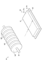
マルチカッターMは、図2に示すように、軸部M1と、複数枚の円盤型カッターM2を備えた切削具である。軸部M1は、回転軸となる軸部材である。図3に示すように、円盤型カッターM2の厚さtは、後記する第一溝41及び第二溝42の幅を決定するものである。隣り合う円盤型カッターM2の間隔gは、未切削領域(フィン3)を決定するものである。
次に、本実施形態に係る溝入れ加工方法について説明する。まずは、切削される部材である被切削金属部材20について説明する。図2に示すように、被切削金属部材20は、直方体を呈するベース部材2と、ベース部材2よりも小さく形成され直方体を呈する被切削ブロック21とからなる。被切削ブロック21の表面(上面)21cの四辺のうち、被切削金属部材20の短手方向に向かい合う一対の辺を第一稜線31、第二稜線32とする。
ベース部材2の表面2aには、被切削ブロック21の周りに露出する平面視矩形枠状の露出部が形成されている。本実施形態においては、被切削金属部材20は、一体的に形成されたものであるが、複数の部材を接合して形成されたものでもよい。また、被切削金属部材20の形状は、ヒートシンク1の使用用途に応じて適宜決定すればよい。
本実施形態に係る溝入れ加工方法は、準備工程と、第一切り込み工程と、第二切り込み工程と、バリ切除工程とを含むものである。
準備工程は、被切削金属部材20及びマルチカッターMを準備する工程である。準備工程では、被切削金属部材20をテーブル(図示省略)に移動不能に固定する。
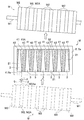
第一切り込み工程は、図3及び図4に示すように、円盤型カッターM2を回転させたマルチカッターMを移動させて被切削ブロック21に第一溝41を形成する工程である。第一切り込み工程では、第一稜線31に対してマルチカッターMの軸部M1を斜めに傾けた状態でマルチカッターMを移動させ切削する。より詳しくは、第一稜線31に直交する基準線Pと、円盤型カッターM2の面内を通る仮想線Qとのなす角度(切り込み角度)がθとなるように設定する。そして、切り込み角度θを維持した状態で、マルチカッターMを第一稜線31から第二稜線32まで移動させる。
マルチカッターMを移動させることにより、被切削ブロック21には複数の第一溝41が等間隔で形成される。ここで、図4の第一溝41のうち、左端の第一溝41を「第一溝41A」と称する。また、左端の第一溝41Aを切削した円盤型カッターM2を「円盤型カッターM2A」と称する。円盤型カッターM2Aは、円盤型カッターM2のうち、左から二番目のものである。
第二切り込み工程は、図5に示すように、円盤型カッターM2を回転させたマルチカッターMを移動させて被切削ブロック21に第二溝42を形成する工程である。第二切り込み工程では、第一稜線31に対してマルチカッターMの軸部M1を斜めに傾けた状態でマルチカッターMを移動させる。マルチカッターMは、第一切り込み工程とは反対側に傾ける。
より詳しくは、第一稜線31に直交する基準線Pと、円盤型カッターM2の面内を通る仮想線Qとのなす角度(切り込み角度)が-θとなるように設定する。そして、円盤型カッターM2Aの進行方向側の左端部M2Aaが、第一溝41の左側入口部41Aaを通るようにして、マルチカッターMを第一稜線31から第二稜線32まで移動させ切削する。言い換えると、第一稜線31上において、第一切り込み工程と第二切り込み工程の円盤型カッターM2の接触位置は同一となるように設定する。これにより、平面視台形のフィン3が等間隔で切り出される。また、第一溝41及び第二溝42によって平面視台形の溝4が形成される(図1参照)。台形を呈する溝4は、台形を呈するフィン3とは反対側の向きで隣接されている。
第一切り込み工程及び第二切り込み工程の切削深さは、適宜設定すればよい。本実施形態では、フィン3(被切削ブロック21)の高さと切削深さを同一としているが、例えば、フィン3(被切削ブロック21)の高さよりも切削深さを小さくしてもよい。
ここで、切り込み角度θの設定について説明する。切り込み角度θは、第一切り込み工程と第二切り込み工程を行った後に、台形のフィン3と台形の溝4が形成されるとともに、溝4内にフィン3と同じ高さの未切削領域が残存しないように適宜設定することが好ましい。
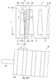
図6に示すように、マルチカッターMの円盤型カッターM2の厚さを厚さtとする。また、円盤型カッターM2間の隙間を隙間gとする。また、第一稜線31から第二稜線32までの稜線間の距離を距離Lとする。第一溝41及び第二溝42は、いずれも円盤型カッターM2で切削されており、また、切り込み角度θは微小なので、その幅寸法wは厚さtと略同一とみなすことができる。したがって、Ltanθ=t/2が成り立つことから、0<2Ltanθ<tを満たすように各要素を設定することが好ましい。
バリ切除工程は、第一切り込み工程及び第二切り込み工程で発生したバリを切除する工程である。
以上説明した本実施形態に係るヒートシンクによれば、溝4(流路)の上流側から下流側に向かうにつれて断面積が徐々に小さくなるが、流路に隣接するフィン3,3の断面積は徐々に大きくなる。これにより、流路の下流側であっても熱交換効率を高めることができる。
また、本実施形態に係る溝入れ加工方法によれば、マルチカッターMを二度移動させるだけで良いため、熱交換効率の高いヒートシンクを容易に製造することができる。また、バリ切除工程を行うことにより、ヒートシンクをきれいに仕上げることができる。
以上本発明の実施形態について説明したが、本発明の趣旨に反しない範囲において適宜設計変更が可能である。例えば、第一切り込み工程は第一稜線31から切り込み、第二切り込み工程は、第二稜線32から切り込んでもよい。また、第一切り込み工程及び第二切り込み工程によって切削された領域内にフィン3と同じ高さの未切削領域が残存した場合は、当該未切削領域を切除して溝を形成してもよい。また、本実施形態の溝入れ加工方法では、ヒートシンクを製造する場合を例示したが、他の部材を製造する場合にも適用可能である。
1 ヒートシンク
2 ベース部材
3 フィン
4 溝(流路)
20 被切削金属部材
21 被切削ブロック
31 第一稜線
32 第二稜線
41 第一溝
42 第二溝
M マルチカッター
M1 軸部
M2 円盤型カッター
2 ベース部材
3 フィン
4 溝(流路)
20 被切削金属部材
21 被切削ブロック
31 第一稜線
32 第二稜線
41 第一溝
42 第二溝
M マルチカッター
M1 軸部
M2 円盤型カッター
Claims (3)
- ベース部材と、前記ベース部材に対して垂直に配設された複数のフィンとを備えたヒートシンクであって、
前記フィンは、平面視台形を呈し、
隣り合う前記フィンの間に形成される複数の流路は前記フィンとは反対向きの平面視台形を呈することを特徴とするヒートシンク。 - 直方体を呈する被切削ブロックと、前記被切削ブロックの底面に配置されたベース部材と、を有する被切削金属部材に、複数枚の円盤型カッターを積層したマルチカッターを回転させながら移動させて溝を形成する溝入れ加工方法であって、
前記被切削ブロックに前記マルチカッターを所定の切り込み角度で挿入し、前記被切削ブロックの対向する稜線の間を移動させて前記被切削ブロックに第一溝を形成する第一切り込み工程と、
前記被切削ブロックに前記マルチカッターを所定の切り込み角度で挿入し、前記被切削ブロックの対向する稜線の間を移動させて前記被切削ブロックに第二溝を形成する第二切り込み工程と、
前記第一切り込み工程及び前記第二切り込み工程では、切り出された複数のフィンが平面視台形を呈するとともに、前記第一溝及び前記第二溝によって形成される複数の流路が前記フィンとは反対向きの平面視台形となるように前記切り込み角度をそれぞれ設定することを特徴とする溝入れ加工方法。 - 前記円盤型カッターの厚みをtとし、
前記被切削ブロックの対向する稜線間の距離をLとし、
前記第一切り込み工程において、前記稜線に直交する基準線に対する前記切り込み角度をθとし、
前記第二切り込み工程において、前記稜線に直交する基準線に対する前記切り込み角度を-θとし、
0<2Ltanθ<tを満たすように設定することを特徴とする請求項2に記載の溝入れ加工方法。
Applications Claiming Priority (2)
| Application Number | Priority Date | Filing Date | Title |
|---|---|---|---|
| JP2018139644A JP2020017631A (ja) | 2018-07-25 | 2018-07-25 | ヒートシンク及び溝入れ加工方法 |
| JP2018-139644 | 2018-07-25 |
Publications (1)
| Publication Number | Publication Date |
|---|---|
| WO2020021777A1 true WO2020021777A1 (ja) | 2020-01-30 |
Family
ID=69181443
Family Applications (1)
| Application Number | Title | Priority Date | Filing Date |
|---|---|---|---|
| PCT/JP2019/015258 Ceased WO2020021777A1 (ja) | 2018-07-25 | 2019-04-08 | ヒートシンク及び溝入れ加工方法 |
Country Status (2)
| Country | Link |
|---|---|
| JP (1) | JP2020017631A (ja) |
| WO (1) | WO2020021777A1 (ja) |
Cited By (2)
| Publication number | Priority date | Publication date | Assignee | Title |
|---|---|---|---|---|
| US10950520B2 (en) * | 2018-11-22 | 2021-03-16 | Siliconware Precision Industries Co., Ltd. | Electronic package, method for fabricating the same, and heat dissipator |
| CN119820855A (zh) * | 2025-01-09 | 2025-04-15 | 深圳市智能派科技有限公司 | 打印头的散热装置 |
Families Citing this family (1)
| Publication number | Priority date | Publication date | Assignee | Title |
|---|---|---|---|---|
| CN113035805A (zh) * | 2021-03-04 | 2021-06-25 | 阳光电源股份有限公司 | 液冷板及功率模组 |
Citations (6)
| Publication number | Priority date | Publication date | Assignee | Title |
|---|---|---|---|---|
| US20070289718A1 (en) * | 2006-06-06 | 2007-12-20 | Mccordic Craig H | Heat sink and method of making same |
| US20080030957A1 (en) * | 2005-05-05 | 2008-02-07 | Abul-Haj Roxanne E | Heatsink method and apparatus |
| JP2013254772A (ja) * | 2012-06-05 | 2013-12-19 | Showa Denko Kk | ヒートシンク及びヒートシンク製造方法 |
| JP2015536813A (ja) * | 2012-10-01 | 2015-12-24 | フォースト・フィジックス・リミテッド・ライアビリティ・カンパニーForced Physics LLC | 温度制御のためのシステムおよび方法 |
| JP2016100456A (ja) * | 2014-11-21 | 2016-05-30 | 日本軽金属株式会社 | 液冷ジャケットの製造方法及び液冷ジャケット |
| JP2017016849A (ja) * | 2015-06-30 | 2017-01-19 | コイト電工株式会社 | 航空灯 |
-
2018
- 2018-07-25 JP JP2018139644A patent/JP2020017631A/ja active Pending
-
2019
- 2019-04-08 WO PCT/JP2019/015258 patent/WO2020021777A1/ja not_active Ceased
Patent Citations (6)
| Publication number | Priority date | Publication date | Assignee | Title |
|---|---|---|---|---|
| US20080030957A1 (en) * | 2005-05-05 | 2008-02-07 | Abul-Haj Roxanne E | Heatsink method and apparatus |
| US20070289718A1 (en) * | 2006-06-06 | 2007-12-20 | Mccordic Craig H | Heat sink and method of making same |
| JP2013254772A (ja) * | 2012-06-05 | 2013-12-19 | Showa Denko Kk | ヒートシンク及びヒートシンク製造方法 |
| JP2015536813A (ja) * | 2012-10-01 | 2015-12-24 | フォースト・フィジックス・リミテッド・ライアビリティ・カンパニーForced Physics LLC | 温度制御のためのシステムおよび方法 |
| JP2016100456A (ja) * | 2014-11-21 | 2016-05-30 | 日本軽金属株式会社 | 液冷ジャケットの製造方法及び液冷ジャケット |
| JP2017016849A (ja) * | 2015-06-30 | 2017-01-19 | コイト電工株式会社 | 航空灯 |
Cited By (2)
| Publication number | Priority date | Publication date | Assignee | Title |
|---|---|---|---|---|
| US10950520B2 (en) * | 2018-11-22 | 2021-03-16 | Siliconware Precision Industries Co., Ltd. | Electronic package, method for fabricating the same, and heat dissipator |
| CN119820855A (zh) * | 2025-01-09 | 2025-04-15 | 深圳市智能派科技有限公司 | 打印头的散热装置 |
Also Published As
| Publication number | Publication date |
|---|---|
| JP2020017631A (ja) | 2020-01-30 |
Similar Documents
| Publication | Publication Date | Title |
|---|---|---|
| JP2020017631A (ja) | ヒートシンク及び溝入れ加工方法 | |
| JP5955651B2 (ja) | ヒートシンク及びヒートシンク製造方法 | |
| JP2015179862A (ja) | ピン付きコールドプレート | |
| JPH07223828A (ja) | ガラス板の切断方法 | |
| JP2016100456A (ja) | 液冷ジャケットの製造方法及び液冷ジャケット | |
| CN215819168U (zh) | 散热器、热交换装置 | |
| JP2009146948A (ja) | 熱交換器用フィンおよびその製造方法 | |
| JP2020017720A (ja) | ヒートシンク | |
| CN113784572A (zh) | 散热器的制造方法 | |
| US20240244795A1 (en) | Heat sink and heat sink production method | |
| JP6119263B2 (ja) | 熱交換器 | |
| CN205961665U (zh) | 一种双斜翅散热器 | |
| CN215956923U (zh) | 散热器、热交换装置 | |
| JP2005252151A (ja) | 冷却装置 | |
| JP6548193B2 (ja) | フィン部材および温度調節装置並びにこれらの製造方法 | |
| CN215735489U (zh) | 散热器、热交换装置 | |
| JP3241536U (ja) | 熱交換装置 | |
| US7461690B2 (en) | Optimally shaped spreader plate for electronics cooling assembly | |
| JP6764765B2 (ja) | 伝熱部材 | |
| JP2017042861A (ja) | ヒートシンクの製造方法 | |
| JP7400056B1 (ja) | 半導体素子搭載用基板 | |
| JP3103735U (ja) | ガイドフィン付きヒートシンク | |
| CN209532266U (zh) | 切割刀体及具有该切割刀体的切割刀具和纵切装置 | |
| JP5356787B2 (ja) | 積層型ルーバー装置およびその製造方法 | |
| CN118352248A (zh) | 一种窄缝式散热板的制作方法 |
Legal Events
| Date | Code | Title | Description |
|---|---|---|---|
| 121 | Ep: the epo has been informed by wipo that ep was designated in this application |
Ref document number: 19840770 Country of ref document: EP Kind code of ref document: A1 |
|
| NENP | Non-entry into the national phase |
Ref country code: DE |
|
| 122 | Ep: pct application non-entry in european phase |
Ref document number: 19840770 Country of ref document: EP Kind code of ref document: A1 |