WO2020021677A1 - 電力変換装置および電力変換システム - Google Patents
電力変換装置および電力変換システム Download PDFInfo
- Publication number
- WO2020021677A1 WO2020021677A1 PCT/JP2018/028094 JP2018028094W WO2020021677A1 WO 2020021677 A1 WO2020021677 A1 WO 2020021677A1 JP 2018028094 W JP2018028094 W JP 2018028094W WO 2020021677 A1 WO2020021677 A1 WO 2020021677A1
- Authority
- WO
- WIPO (PCT)
- Prior art keywords
- power
- power conversion
- load
- storage battery
- conversion device
- Prior art date
- Legal status (The legal status is an assumption and is not a legal conclusion. Google has not performed a legal analysis and makes no representation as to the accuracy of the status listed.)
- Ceased
Links
Images


Classifications
-
- H—ELECTRICITY
- H02—GENERATION; CONVERSION OR DISTRIBUTION OF ELECTRIC POWER
- H02M—APPARATUS FOR CONVERSION BETWEEN AC AND AC, BETWEEN AC AND DC, OR BETWEEN DC AND DC, AND FOR USE WITH MAINS OR SIMILAR POWER SUPPLY SYSTEMS; CONVERSION OF DC OR AC INPUT POWER INTO SURGE OUTPUT POWER; CONTROL OR REGULATION THEREOF
- H02M1/00—Details of apparatus for conversion
- H02M1/36—Means for starting or stopping converters
-
- H—ELECTRICITY
- H02—GENERATION; CONVERSION OR DISTRIBUTION OF ELECTRIC POWER
- H02J—ELECTRIC POWER NETWORKS; CIRCUIT ARRANGEMENTS OR SYSTEMS FOR SUPPLYING OR DISTRIBUTING ELECTRIC POWER; SYSTEMS FOR STORING ELECTRIC ENERGY
- H02J3/00—Circuit arrangements for AC mains or AC distribution networks
- H02J3/38—Arrangements for feeding a single network from two or more generators or sources in parallel; Arrangements for feeding already energised networks from additional generators or sources in parallel
- H02J3/381—Dispersed generators
-
- H—ELECTRICITY
- H02—GENERATION; CONVERSION OR DISTRIBUTION OF ELECTRIC POWER
- H02J—ELECTRIC POWER NETWORKS; CIRCUIT ARRANGEMENTS OR SYSTEMS FOR SUPPLYING OR DISTRIBUTING ELECTRIC POWER; SYSTEMS FOR STORING ELECTRIC ENERGY
- H02J13/00—Circuit arrangements for providing remote monitoring or remote control of equipment in a power distribution network
- H02J13/18—Circuit arrangements for providing remote monitoring or remote control of equipment in a power distribution network characterised by the remotely-controlled equipment, e.g. converters or transformers
- H02J13/34—Circuit arrangements for providing remote monitoring or remote control of equipment in a power distribution network characterised by the remotely-controlled equipment, e.g. converters or transformers the equipment being switches, relays or circuit breakers
-
- H—ELECTRICITY
- H02—GENERATION; CONVERSION OR DISTRIBUTION OF ELECTRIC POWER
- H02J—ELECTRIC POWER NETWORKS; CIRCUIT ARRANGEMENTS OR SYSTEMS FOR SUPPLYING OR DISTRIBUTING ELECTRIC POWER; SYSTEMS FOR STORING ELECTRIC ENERGY
- H02J7/00—Circuit arrangements for charging or discharging batteries or for supplying loads from batteries
- H02J7/34—Parallel operation in networks using both storage and other DC sources, e.g. providing buffering
- H02J7/35—Parallel operation in networks using both storage and other DC sources, e.g. providing buffering with light sensitive cells
-
- H—ELECTRICITY
- H02—GENERATION; CONVERSION OR DISTRIBUTION OF ELECTRIC POWER
- H02J—ELECTRIC POWER NETWORKS; CIRCUIT ARRANGEMENTS OR SYSTEMS FOR SUPPLYING OR DISTRIBUTING ELECTRIC POWER; SYSTEMS FOR STORING ELECTRIC ENERGY
- H02J7/00—Circuit arrangements for charging or discharging batteries or for supplying loads from batteries
- H02J7/865—Battery or charger load switching, e.g. concurrent charging and load supply
-
- H—ELECTRICITY
- H02—GENERATION; CONVERSION OR DISTRIBUTION OF ELECTRIC POWER
- H02J—ELECTRIC POWER NETWORKS; CIRCUIT ARRANGEMENTS OR SYSTEMS FOR SUPPLYING OR DISTRIBUTING ELECTRIC POWER; SYSTEMS FOR STORING ELECTRIC ENERGY
- H02J7/00—Circuit arrangements for charging or discharging batteries or for supplying loads from batteries
- H02J7/90—Regulation of charging or discharging current or voltage
- H02J7/933—Regulation of charging or discharging current or voltage the cycle being controlled or terminated in response to electric parameters
-
- H—ELECTRICITY
- H02—GENERATION; CONVERSION OR DISTRIBUTION OF ELECTRIC POWER
- H02M—APPARATUS FOR CONVERSION BETWEEN AC AND AC, BETWEEN AC AND DC, OR BETWEEN DC AND DC, AND FOR USE WITH MAINS OR SIMILAR POWER SUPPLY SYSTEMS; CONVERSION OF DC OR AC INPUT POWER INTO SURGE OUTPUT POWER; CONTROL OR REGULATION THEREOF
- H02M7/00—Conversion of AC power input into DC power output; Conversion of DC power input into AC power output
- H02M7/42—Conversion of DC power input into AC power output without possibility of reversal
- H02M7/44—Conversion of DC power input into AC power output without possibility of reversal by static converters
- H02M7/48—Conversion of DC power input into AC power output without possibility of reversal by static converters using discharge tubes with control electrode or semiconductor devices with control electrode
-
- H—ELECTRICITY
- H02—GENERATION; CONVERSION OR DISTRIBUTION OF ELECTRIC POWER
- H02J—ELECTRIC POWER NETWORKS; CIRCUIT ARRANGEMENTS OR SYSTEMS FOR SUPPLYING OR DISTRIBUTING ELECTRIC POWER; SYSTEMS FOR STORING ELECTRIC ENERGY
- H02J2101/00—Supply or distribution of decentralised, dispersed or local electric power generation
- H02J2101/20—Dispersed power generation using renewable energy sources
- H02J2101/22—Solar energy
- H02J2101/24—Photovoltaics
-
- H—ELECTRICITY
- H02—GENERATION; CONVERSION OR DISTRIBUTION OF ELECTRIC POWER
- H02J—ELECTRIC POWER NETWORKS; CIRCUIT ARRANGEMENTS OR SYSTEMS FOR SUPPLYING OR DISTRIBUTING ELECTRIC POWER; SYSTEMS FOR STORING ELECTRIC ENERGY
- H02J9/00—Circuit arrangements for emergency or stand-by power supply, e.g. for emergency lighting
- H02J9/04—Circuit arrangements for emergency or stand-by power supply, e.g. for emergency lighting in which the distribution system is disconnected from the normal source and connected to a standby source
- H02J9/06—Circuit arrangements for emergency or stand-by power supply, e.g. for emergency lighting in which the distribution system is disconnected from the normal source and connected to a standby source with automatic change-over, e.g. UPS systems
- H02J9/062—Circuit arrangements for emergency or stand-by power supply, e.g. for emergency lighting in which the distribution system is disconnected from the normal source and connected to a standby source with automatic change-over, e.g. UPS systems for AC powered loads
-
- Y—GENERAL TAGGING OF NEW TECHNOLOGICAL DEVELOPMENTS; GENERAL TAGGING OF CROSS-SECTIONAL TECHNOLOGIES SPANNING OVER SEVERAL SECTIONS OF THE IPC; TECHNICAL SUBJECTS COVERED BY FORMER USPC CROSS-REFERENCE ART COLLECTIONS [XRACs] AND DIGESTS
- Y02—TECHNOLOGIES OR APPLICATIONS FOR MITIGATION OR ADAPTATION AGAINST CLIMATE CHANGE
- Y02B—CLIMATE CHANGE MITIGATION TECHNOLOGIES RELATED TO BUILDINGS, e.g. HOUSING, HOUSE APPLIANCES OR RELATED END-USER APPLICATIONS
- Y02B10/00—Integration of renewable energy sources in buildings
- Y02B10/70—Hybrid systems, e.g. uninterruptible or back-up power supplies integrating renewable energies
-
- Y—GENERAL TAGGING OF NEW TECHNOLOGICAL DEVELOPMENTS; GENERAL TAGGING OF CROSS-SECTIONAL TECHNOLOGIES SPANNING OVER SEVERAL SECTIONS OF THE IPC; TECHNICAL SUBJECTS COVERED BY FORMER USPC CROSS-REFERENCE ART COLLECTIONS [XRACs] AND DIGESTS
- Y02—TECHNOLOGIES OR APPLICATIONS FOR MITIGATION OR ADAPTATION AGAINST CLIMATE CHANGE
- Y02B—CLIMATE CHANGE MITIGATION TECHNOLOGIES RELATED TO BUILDINGS, e.g. HOUSING, HOUSE APPLIANCES OR RELATED END-USER APPLICATIONS
- Y02B70/00—Technologies for an efficient end-user side electric power management and consumption
- Y02B70/30—Systems integrating technologies related to power network operation and communication or information technologies for improving the carbon footprint of the management of residential or tertiary loads, i.e. smart grids as climate change mitigation technology in the buildings sector, including also the last stages of power distribution and the control, monitoring or operating management systems at local level
-
- Y—GENERAL TAGGING OF NEW TECHNOLOGICAL DEVELOPMENTS; GENERAL TAGGING OF CROSS-SECTIONAL TECHNOLOGIES SPANNING OVER SEVERAL SECTIONS OF THE IPC; TECHNICAL SUBJECTS COVERED BY FORMER USPC CROSS-REFERENCE ART COLLECTIONS [XRACs] AND DIGESTS
- Y02—TECHNOLOGIES OR APPLICATIONS FOR MITIGATION OR ADAPTATION AGAINST CLIMATE CHANGE
- Y02B—CLIMATE CHANGE MITIGATION TECHNOLOGIES RELATED TO BUILDINGS, e.g. HOUSING, HOUSE APPLIANCES OR RELATED END-USER APPLICATIONS
- Y02B90/00—Enabling technologies or technologies with a potential or indirect contribution to GHG emissions mitigation
- Y02B90/20—Smart grids as enabling technology in buildings sector
-
- Y—GENERAL TAGGING OF NEW TECHNOLOGICAL DEVELOPMENTS; GENERAL TAGGING OF CROSS-SECTIONAL TECHNOLOGIES SPANNING OVER SEVERAL SECTIONS OF THE IPC; TECHNICAL SUBJECTS COVERED BY FORMER USPC CROSS-REFERENCE ART COLLECTIONS [XRACs] AND DIGESTS
- Y02—TECHNOLOGIES OR APPLICATIONS FOR MITIGATION OR ADAPTATION AGAINST CLIMATE CHANGE
- Y02E—REDUCTION OF GREENHOUSE GAS [GHG] EMISSIONS, RELATED TO ENERGY GENERATION, TRANSMISSION OR DISTRIBUTION
- Y02E10/00—Energy generation through renewable energy sources
- Y02E10/50—Photovoltaic [PV] energy
- Y02E10/56—Power conversion systems, e.g. maximum power point trackers
-
- Y—GENERAL TAGGING OF NEW TECHNOLOGICAL DEVELOPMENTS; GENERAL TAGGING OF CROSS-SECTIONAL TECHNOLOGIES SPANNING OVER SEVERAL SECTIONS OF THE IPC; TECHNICAL SUBJECTS COVERED BY FORMER USPC CROSS-REFERENCE ART COLLECTIONS [XRACs] AND DIGESTS
- Y02—TECHNOLOGIES OR APPLICATIONS FOR MITIGATION OR ADAPTATION AGAINST CLIMATE CHANGE
- Y02E—REDUCTION OF GREENHOUSE GAS [GHG] EMISSIONS, RELATED TO ENERGY GENERATION, TRANSMISSION OR DISTRIBUTION
- Y02E60/00—Enabling technologies; Technologies with a potential or indirect contribution to GHG emissions mitigation
-
- Y—GENERAL TAGGING OF NEW TECHNOLOGICAL DEVELOPMENTS; GENERAL TAGGING OF CROSS-SECTIONAL TECHNOLOGIES SPANNING OVER SEVERAL SECTIONS OF THE IPC; TECHNICAL SUBJECTS COVERED BY FORMER USPC CROSS-REFERENCE ART COLLECTIONS [XRACs] AND DIGESTS
- Y04—INFORMATION OR COMMUNICATION TECHNOLOGIES HAVING AN IMPACT ON OTHER TECHNOLOGY AREAS
- Y04S—SYSTEMS INTEGRATING TECHNOLOGIES RELATED TO POWER NETWORK OPERATION, COMMUNICATION OR INFORMATION TECHNOLOGIES FOR IMPROVING THE ELECTRICAL POWER GENERATION, TRANSMISSION, DISTRIBUTION, MANAGEMENT OR USAGE, i.e. SMART GRIDS
- Y04S10/00—Systems supporting electrical power generation, transmission or distribution
- Y04S10/18—Systems supporting electrical power generation, transmission or distribution using switches, relays or circuit breakers, e.g. intelligent electronic devices [IED]
-
- Y—GENERAL TAGGING OF NEW TECHNOLOGICAL DEVELOPMENTS; GENERAL TAGGING OF CROSS-SECTIONAL TECHNOLOGIES SPANNING OVER SEVERAL SECTIONS OF THE IPC; TECHNICAL SUBJECTS COVERED BY FORMER USPC CROSS-REFERENCE ART COLLECTIONS [XRACs] AND DIGESTS
- Y04—INFORMATION OR COMMUNICATION TECHNOLOGIES HAVING AN IMPACT ON OTHER TECHNOLOGY AREAS
- Y04S—SYSTEMS INTEGRATING TECHNOLOGIES RELATED TO POWER NETWORK OPERATION, COMMUNICATION OR INFORMATION TECHNOLOGIES FOR IMPROVING THE ELECTRICAL POWER GENERATION, TRANSMISSION, DISTRIBUTION, MANAGEMENT OR USAGE, i.e. SMART GRIDS
- Y04S20/00—Management or operation of end-user stationary applications or the last stages of power distribution; Controlling, monitoring or operating thereof
- Y04S20/12—Energy storage units, uninterruptible power supply [UPS] systems or standby or emergency generators, e.g. in the last power distribution stages
-
- Y—GENERAL TAGGING OF NEW TECHNOLOGICAL DEVELOPMENTS; GENERAL TAGGING OF CROSS-SECTIONAL TECHNOLOGIES SPANNING OVER SEVERAL SECTIONS OF THE IPC; TECHNICAL SUBJECTS COVERED BY FORMER USPC CROSS-REFERENCE ART COLLECTIONS [XRACs] AND DIGESTS
- Y04—INFORMATION OR COMMUNICATION TECHNOLOGIES HAVING AN IMPACT ON OTHER TECHNOLOGY AREAS
- Y04S—SYSTEMS INTEGRATING TECHNOLOGIES RELATED TO POWER NETWORK OPERATION, COMMUNICATION OR INFORMATION TECHNOLOGIES FOR IMPROVING THE ELECTRICAL POWER GENERATION, TRANSMISSION, DISTRIBUTION, MANAGEMENT OR USAGE, i.e. SMART GRIDS
- Y04S20/00—Management or operation of end-user stationary applications or the last stages of power distribution; Controlling, monitoring or operating thereof
- Y04S20/20—End-user application control systems
- Y04S20/248—UPS systems or standby or emergency generators
Definitions
- the present invention relates to a power conversion device and a power conversion system.
- the present invention has been made to solve the above-described problem, and has been improved so as to suppress the system control from becoming unstable when the remaining power amount of the storage battery decreases during the independent operation. It is an object to provide a power conversion device and a power conversion system.
- the first power conversion system is connected to a storage battery and is constructed so as to be interconnected with a power system, and supplies power to the load device by converting the power of the storage battery and outputting it to a connection point between the load device and the power system.
- a first power converter At the time of self-sustained operation in which the power system is disconnected from the first power conversion device, when the state of the storage battery meets a predetermined remaining power shortage condition, the load device Control means for transmitting a load adjustment signal for reducing the power supplied to the Is provided.
- the second power conversion system is connected to a storage battery and is constructed so as to be interconnected with a power system, and supplies power to the load device by converting the power of the storage battery and outputting it to a connection point between the load device and the power system.
- a first power conversion device A second power conversion device connected to a solar cell panel and converting the power generated by the solar cell panel to supply the connection point between the load device and the power system, In the independent operation in which the power system is disconnected from the first power conversion device, when the state of the storage battery meets a predetermined remaining power shortage condition, the operation of the first power conversion device is stopped and the second Control means for transmitting a cooperative stop signal to the second power conversion device for performing the operation stop of the power conversion device in coordination, Is provided.
- the first power conversion system when the remaining power of the storage battery decreases, a control instruction for reducing the power supplied to the load device can be issued. This can prevent unstable power control from being performed as the whole power conversion system.
- the second power conversion system when the remaining power amount of the storage battery is reduced, by performing the cooperative stop, it is possible to prevent unstable power control of the entire power conversion system.
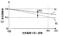
- FIG. 1 is a diagram showing a power conversion system according to an embodiment. It is a figure showing stop operation of a power conversion system concerning an embodiment.
- 5 is a flowchart of a routine executed by the power conversion system according to the embodiment. 5 is a flowchart of a routine executed by the power conversion system according to the embodiment. It is a figure showing an example of the storage battery state of the power conversion system concerning an embodiment. It is a figure showing an example of the storage battery state of the power conversion system concerning an embodiment.
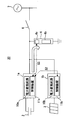
- FIG. 9 is a diagram illustrating a power conversion device and a power conversion system according to a modification of the embodiment.
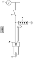
- FIG. 4 is a diagram illustrating a power conversion device and a power conversion system according to a comparative example. It is a figure showing stop operation of a power converter and a power conversion system concerning a comparative example.
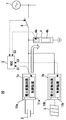
- FIG. 1 is a diagram illustrating a power conversion system 20 according to the embodiment.
- the power conversion system 20 includes a storage battery 2, a solar cell array 3 including a plurality of solar cell panels, a load device 4, an MSC (main site controller) 5, which is a higher-level monitoring device, a circuit breaker 6, a first power conversion device, and the like.
- the device includes a device 1a and a second power converter 1b.
- the first power conversion device 1a includes a first power conversion circuit 10a and a first control device 11a.
- the first power conversion circuit 10a is an inverter circuit that performs DC / AC conversion, and includes a semiconductor switching element and the like.
- the first control device 11a performs switching control and the like of a semiconductor switching element included in the first power conversion circuit 10a.
- the first power converter 1a is connected to the storage battery 2.
- the first power converter 1a is constructed so as to be interconnected with the power system 7.
- the first control device 11a controls the first power conversion circuit 10a
- the power of the storage battery 2 is converted and supplied to the connection point between the load device 4 and the power system 7.
- the first power conversion device 1a supplies power to the load device 4.
- the first control device 11a may drive the first power conversion circuit 10a in the storage battery charging mode.
- the storage battery charging mode is an operation mode in which the storage battery 2 is charged by converting the system voltage of the power system 7.
- the second power converter 1b includes a second power converter 10b and a second controller 11b.
- the second power conversion circuit 10b is an inverter circuit that performs DC / AC conversion, and includes a semiconductor switching element and the like.
- the second control device 11b performs switching control of a semiconductor switching element included in the second power conversion circuit 10b, and the like.
- the second power converter 1b is connected to the solar cell array 3.
- the output end of the second power conversion circuit 10b is connected to a connection point between the load device 4 and the first power conversion device 1a, and is also connected to the power system 7 via this connection point.
- the second power converter 1b is constructed so as to be interconnected with the power system 7.
- the second control device 11b controls the second power conversion circuit 10b
- the power generated by the solar cell array 3 is converted and supplied to the connection point between the load device 4 and the first power conversion device 1a. .
- the second power converter 1b supplies power to the load device 4.
- the load device 4 includes a load body 4b and a load control unit 4a that controls the load body 4b according to the command value.
- the load body 4b is an inductive load or a resistive load.
- One end of the circuit breaker 6 is connected to the power system 7.
- the other end of the circuit breaker 6 is connected to a wiring unit where the load device 4, the first power converter 1a, and the second power converter 1b are connected to each other.
- the load system 4 When the circuit breaker 6 is turned off, the load system 4, the first power converter 1a, and the second power converter 1b are disconnected from the power system 7. After the power system 7 is disconnected, the first power converter 1a and the second power converter 1b continue to generate power in the “independent operation mode”.
- the MSC 5 is connected to each of the first power conversion circuit 10a, the second power conversion circuit 10b, the load control unit 4a, and the circuit breaker 6 so as to be able to communicate wirelessly or by wire.
- the CMSC 5 transmits the load adjustment signal S3 to the load control unit 4a when the state of the storage battery 2 meets the predetermined remaining power shortage condition during the operation in the above-mentioned independent operation mode.
- the load adjustment signal S3 is a signal transmitted to the load control unit 4a to cause the load control unit 4a to perform an operation for reducing the power consumption of the load main body 4b.
- the “remaining power shortage condition” may include that the remaining power amount of the storage battery 2 has reached a predetermined lower limit, and the first power conversion device 1 a This may include the fact that the remaining operation time T op capable of outputting electric power has become equal to or less than a predetermined lower limit time.
- the MSC 5 transmits the cooperative stop signal S2 to the second power converter 1b.
- the cooperative stop signal S2 is a signal for stopping the operation of the second power converter 1b in accordance with the stop time of the operation of the first power converter 1a.
- the first power conversion device 1b on the photovoltaic power generation system side does not continue to operate alone.
- 1a and the 2nd power converter 1b can be stopped cooperatively. By performing the cooperative stop, unstable power control can be prevented from being performed as the whole power conversion system 20.
- the cooperative stop signal S2 and the load adjustment are sent to the second power converter 1b and the load control unit 4a.
- the signal S3 is transmitted.
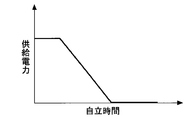
- FIG. 2 is a diagram illustrating a stop operation of the power conversion system 20 according to the embodiment.
- the MSC 5 controls the power conversion system 20 so as to reduce the power supplied to the load device 4 at the rate of change shown in FIG. 2 when the state of the storage battery 2 meets a predetermined remaining power shortage condition.
- the MSC 5 may reduce the power command value provided to the first power conversion device 1a such that the load supply power provided to the load device 4 gradually decreases at a predetermined reduction rate.
- the power conversion system 20 during the self-sustaining operation can be gently stopped, so that a sudden stop of the power supply to the load devices 4 can be suppressed.
- the second power converter 1b may also be gently stopped so that the output power decreases as shown in FIG.
- FIG. 8 is a diagram illustrating a power conversion device and a power conversion system according to a comparative example.
- FIG. 9 is a diagram illustrating a stop operation of the power conversion device and the power conversion system according to the comparative example. As illustrated in FIG. 9, it is not preferable that the load supply power suddenly decreases due to the sudden stop of the operation of the first power converter 1a and the second power converter 1b. In this regard, according to the embodiment, it is possible to reliably suppress sudden interruption of power supply to the load device 4.
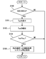
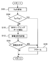
- FIGS. 3 and 4 are flowcharts of a routine executed by the power conversion system 20 according to the embodiment.
- the routine shown in FIGS. 3 and 4 is stored in the MSC 5 in advance in the form of a program.
- the flowchart of FIG. 3 shows a process of calculating the remaining operation time Top in which the first power converter 1a can output power based on the remaining power amount of the storage battery 2.
- the MSC 5 executes a process of determining whether or not the latest SOC (State of Charge: state of charge) in the storage battery 2 is equal to or less than a predetermined threshold value SOCth (step S100). .
- the MSC 5 calculates the SOC of the storage battery 2 by continuously receiving electrical information such as the voltage value and the current value of the storage battery 2 from the first control device 11a.
- step S100 If the determination result of step S100 is negative (NO), the current routine ends.
- step S101 MSC 5 calculates the remaining operation time T op (step S101).
- the remaining operation time Top may be calculated based on the remaining power amount determined from the SOC [%] at the current time and the power consumption of the load device 4 at the current time.
- the power consumption of the load device 4 for example, a value of the average power consumption of the load device 4 during a predetermined period may be used.
- the SOC trend may be accumulated.
- the accumulation of the SOC trend is to record the decreasing trend of the SOC accompanying the power supply to the load device 4 over a predetermined period.
- Various SOC consumptions include a high power consumption operation in which the SOC of the storage battery 2 decreases relatively quickly due to accumulation of the SOC trend, and a low power consumption operation in which the SOC of the storage battery 2 decreases relatively slowly. The trend is recorded.
- the remaining operation time Top can be calculated with higher accuracy.
- the average value of the SOC reduction rate, median SOC decreasing rate, and based on such local maximum value of the SOC decrease rate may include estimating the remaining operating time T op from the current SOC.
- step S102 the remaining operation time Top calculated in step S101 is notified (step S102).
- the system monitoring terminal such as numbers or percentage of remaining operating time T op may be displayed from MSC 5.
- step S104 the MSC 5 executes a process of determining whether or not the remaining operation time T op is equal to or less than a predetermined lower threshold T opL (step S104). If the result of the determination in step S104 is negative (NO), the current routine ends.
- step S104 determines whether the determination result of step S104 is affirmative (YES). If the determination result of step S104 is affirmative (YES), SOC ⁇ SOCth and T op ⁇ Top L are satisfied .
- the MSC 5 executes the above-described communication processing to the “other device” and executes the system stop processing (step S106). In the process of communicating with the “other device”, the MSC 5 outputs the cooperative stop signal S2 and the load adjustment signal S3 described above. In the system stop processing, the stop signal S1 is issued to the first power conversion device 1a, and the first power conversion device 1a is gradually cut off as described with reference to FIG. Then, the current routine ends.
- the flowchart of FIG. 4 includes a process of acquiring a change over time in the storage capacity of the storage battery 2.
- the processing of steps S101 and S104 described in the routine of FIG. 3 is executed. If the determination result in step S104 is affirmative (YES), the MSC 5 executes an alarm process for sounding an alarm using an alarm device or a system monitoring terminal (step S120).
- step S104 If the result of the determination in step S104 is negative (NO), the MSC 5 reads the SOC sampling data (step S110). It is assumed that the MSC 5 samples the SOC in time series over a predetermined period.
- the MSC 5 performs storage battery characteristic evaluation based on the SOC sampling data (step S112).
- Various known techniques can be used for the evaluation of the storage battery characteristics. Specific examples are shown below.
- FIGS. 5 and 6 are diagrams illustrating an example of a storage battery state of the power conversion system 20 according to the embodiment.
- the SOC of the storage battery 2 decreases, and when a preset charging condition is satisfied, the storage battery charging mode is set, and the storage battery 2 is charged to reduce the SOC. Recover. In some cases, the SOC is charged to almost 100% in the storage battery charging mode, as indicated by the characteristic 50 in FIG.
- the SOC may not be sufficiently recovered by charging as shown by the characteristics 51 and 52. Therefore, when the SOC does not recover to a predetermined SOC level by charging, it may be considered that the characteristics of the storage battery 2 are abnormal or the storage battery 2 is deteriorated.
- the capacity retention rate of the storage battery 2 generally decreases in proportion to the number of charge / discharge repetitions. If the actual characteristic 62 deviates from the reference characteristic 61 beyond a predetermined reference width Dth, the storage battery 2 may be regarded as abnormal.
- the degree of progress of consumption of the storage battery 2 may be evaluated based on whether or not the capacity maintenance ratio is lower than a predetermined reference maintenance ratio Pth. Further, the degree of progress of consumption of the storage battery 2 may be evaluated based on whether or not the number of charge / discharge repetitions has reached a predetermined reference number Nth.
- Step S118 the MSC 5 executes a process of determining whether or not the storage battery 2 has reached the end of its life based on the result of the storage battery characteristic evaluation in Step S112 (Step S118). If the decision result in the step S118 is negative (NO), the current routine ends.
- step S118 If the determination result in step S118 is affirmative (YES), the alarm processing in step S120 is performed, and then the current routine ends.
- FIG. 7 is a diagram showing a first power conversion device 1a and a power conversion system 20 according to a modification of the embodiment.
- the MSC 5 is omitted, and instead of the MSC 5, the first control device 11a built in the first power conversion device 1a executes each control operation according to the above-described embodiment.
- the first control device 11a transmits the cooperative stop signal S2 and the load adjustment signal S3 to the load control unit 4a and the second control unit. Transmit to the device 11b. Other operations of the MSC 5 are similarly executed by the first control device 11a.
- the first power conversion device 1a is provided which is improved so as to suppress an adverse effect caused by a sudden interruption of the power supply to the load device 4.
- all of the following characteristic configurations (A) to (D) are mounted on the same power conversion system 20.
- the load supply power is reduced by transmitting the load adjustment signal S3 to the load control unit 4a.
- the first power converter 1a and the second power converter 1b are cooperatively stopped by transmitting the cooperative stop signal S2 to the second power converter 1b.
- the configuration (C) is for calculating the remaining operation time Top of the storage battery 2 and performing various evaluations of the storage battery 2.
- at least the output power of the first power converter 1a is gradually reduced at a predetermined reduction rate to perform soft load power cutoff.
- a power conversion system 20 having one or more of the characteristic configurations (A) to (D) may be provided.
Landscapes
- Engineering & Computer Science (AREA)
- Power Engineering (AREA)
- Charge And Discharge Circuits For Batteries Or The Like (AREA)
- Supply And Distribution Of Alternating Current (AREA)
- Inverter Devices (AREA)
Abstract
電力変換システムは、蓄電池と、電力系統と系統連系するように構築され、蓄電池の電力を変換して負荷機器と電力系統との間の接続点に出力することで、負荷機器に電力を供給する第一電力変換装置と、電力系統が第一電力変換装置から切り離された自立運転時において、蓄電池の状態が予め定めた残電力不足条件に合致した場合に、第一電力変換装置ではない他の装置に対して負荷機器に供給される電力を低減するための信号を送信する制御手段と、を備える。負荷機器は、負荷本体と、指令値に従って負荷本体を制御する負荷制御部と、を含んでもよい。負荷機器制御部が、上記の他の装置であり、信号は、負荷本体の消費電力を低下させる運転を負荷制御部が行うように負荷制御部に対して送信する負荷調整信号を含んでもよい。
Description
本発明は、電力変換装置および電力変換システムに関するものである。
従来、例えば日本特開2017-112762号公報に記載されているように、蓄電装置が遮断されたときに電力変換装置の停止処理を実行する電力変換システムが知られている。
上記従来の技術では、蓄電池の側に何らかの異常が検出されたときに、蓄電池と接続された電力変換装置の出力電力を急峻に低下させている。電力変換装置の急停止が突然に発生すると、このような急停止は電力変換装置以外の他の装置にとって予期しない停止動作となる可能性が高い。
系統連系システムの自立運転中には電力系統からの電力供給を受けられないので、上記のような予期しない停止動作が起きると種々の問題が発生する。例えば負荷機器にとっては、供給電力が突然に遮断されてしまう。例えば蓄電池以外の電源と接続する他の電力変換装置にとっては、自立運転の安定性が突然に低下してしまう。これらの事態により、システム全体としての制御安定性が低下するという問題がある。
本発明は、上述のような課題を解決するためになされたもので、自立運転時において蓄電池の残電力量が低下したときにシステムの制御が不安定になることを抑制するように改良された電力変換装置および電力変換システムを提供することを目的とする。
本出願の実施形態の一つにかかる第一の電力変換システムは、
蓄電池と接続され、電力系統と系統連系するように構築され、前記蓄電池の電力を変換して負荷機器と前記電力系統との間の接続点に出力することで前記負荷機器に電力を供給する第一電力変換装置と、
前記電力系統が前記第一電力変換装置から切り離された自立運転時において、前記蓄電池の状態が予め定めた残電力不足条件に合致した場合に、前記負荷機器の負荷制御部に対して前記負荷機器に供給される電力を低減するための負荷調整信号を送信する制御手段と、
を備える。
蓄電池と接続され、電力系統と系統連系するように構築され、前記蓄電池の電力を変換して負荷機器と前記電力系統との間の接続点に出力することで前記負荷機器に電力を供給する第一電力変換装置と、
前記電力系統が前記第一電力変換装置から切り離された自立運転時において、前記蓄電池の状態が予め定めた残電力不足条件に合致した場合に、前記負荷機器の負荷制御部に対して前記負荷機器に供給される電力を低減するための負荷調整信号を送信する制御手段と、
を備える。
本出願の実施形態の一つにかかる第二の電力変換システムは、
蓄電池と接続され、電力系統と系統連系するように構築され、前記蓄電池の電力を変換して負荷機器と前記電力系統との間の接続点に出力することで、前記負荷機器に電力を供給する第一電力変換装置と、
太陽電池パネルと接続され、前記太陽電池パネルで発電した電力を変換して前記負荷機器と前記電力系統との前記接続点に供給する第二電力変換装置と、
前記電力系統が前記第一電力変換装置から切り離された自立運転時において、前記蓄電池の状態が予め定めた残電力不足条件に合致した場合に、前記第一電力変換装置の運転停止と前記第二電力変換装置の運転停止とを協調させて行うための協調停止信号を前記第二電力変換装置に送信する制御手段と、
を備える。
蓄電池と接続され、電力系統と系統連系するように構築され、前記蓄電池の電力を変換して負荷機器と前記電力系統との間の接続点に出力することで、前記負荷機器に電力を供給する第一電力変換装置と、
太陽電池パネルと接続され、前記太陽電池パネルで発電した電力を変換して前記負荷機器と前記電力系統との前記接続点に供給する第二電力変換装置と、
前記電力系統が前記第一電力変換装置から切り離された自立運転時において、前記蓄電池の状態が予め定めた残電力不足条件に合致した場合に、前記第一電力変換装置の運転停止と前記第二電力変換装置の運転停止とを協調させて行うための協調停止信号を前記第二電力変換装置に送信する制御手段と、
を備える。
上記第一の電力変換システムによれば、蓄電池の残電力量が低下した場合に、負荷機器に供給される電力を低減するための制御指示を発することができる。これにより、電力変換システム全体として不安定な電力制御が行われることを防止できる。
上記第二の電力変換システムによれば、蓄電池の残電力量が低下した場合に、協調停止を行うことにより電力変換システム全体として不安定な電力制御が行われることを防止できる。
図1は、実施の形態にかかる電力変換システム20を示す図である。電力変換システム20は、蓄電池2と、複数の太陽電池パネルを含む太陽電池アレイ3と、負荷機器4と、上位監視装置であるMSC(メインサイトコントローラ)5と、遮断器6と、第一電力変換装置1aと、第二電力変換装置1bと、を備える。
第一電力変換装置1aは、第一電力変換回路10aと、第一制御装置11aとを備えている。第一電力変換回路10aは、直流交流変換を行うインバータ回路であり、半導体スイッチング素子などで構成されている。第一制御装置11aは、第一電力変換回路10aを構成する半導体スイッチング素子のスイッチング制御等を行う。
第一電力変換装置1aは、蓄電池2と接続されている。第一電力変換装置1aは、電力系統7と系統連系するように構築されている。第一制御装置11aが第一電力変換回路10aを制御することで、蓄電池2の電力が変換されて負荷機器4と電力系統7との間の接続点に供給されている。これにより、第一電力変換装置1aは、負荷機器4に電力を供給する。
第一制御装置11aは、蓄電池充電モードで第一電力変換回路10aを駆動してもよい。蓄電池充電モードとは、電力系統7の系統電圧を変換することで蓄電池2を充電する運転モードのことである。
第二電力変換装置1bは、第二電力変換回路10bと、第二制御装置11bとを備えている。第二電力変換回路10bは、直流交流変換を行うインバータ回路であり、半導体スイッチング素子などで構成されている。第二制御装置11bは、第二電力変換回路10bを構成する半導体スイッチング素子のスイッチング制御等を行う。
第二電力変換装置1bは、太陽電池アレイ3と接続されている。第二電力変換回路10bの出力端は、負荷機器4と第一電力変換装置1aの間の接続点に接続されており、この接続点を介して電力系統7とも接続している。
第二電力変換装置1bは、電力系統7と系統連系するように構築されている。第二制御装置11bが第二電力変換回路10bを制御することで、太陽電池アレイ3で発電された電力が変換されて負荷機器4と第一電力変換装置1aの間の接続点に供給される。これにより、第二電力変換装置1bは、負荷機器4に電力を供給する。
負荷機器4は、負荷本体4bと、指令値に従って負荷本体4bを制御する負荷制御部4aと、を含んでいる。負荷本体4bは、誘導負荷または抵抗負荷であるものとする。
遮断器6の一端は電力系統7に接続されている。遮断器6の他端は、負荷機器4、第一電力変換装置1aおよび第二電力変換装置1bが互いに接続された配線部に接続している。遮断器6がターンオフされると、負荷機器4、第一電力変換装置1aおよび第二電力変換装置1bが、電力系統7が切り離される。電力系統7が切り離された後は、第一電力変換装置1aおよび第二電力変換装置1bが「自立運転モード」で発電を継続する。
MSC5は、第一電力変換回路10a、第二電力変換回路10b、負荷制御部4a、および遮断器6それぞれと、無線または有線で通信可能に接続されている。
MSC5は、上記の自立運転モードでの運転時において、蓄電池2の状態が予め定めた残電力不足条件に合致した場合に、負荷制御部4aに対して負荷調整信号S3を送信する。負荷調整信号S3は、負荷本体4bの消費電力を低下させる運転を負荷制御部4aに行わせるために負荷制御部4aに対して送信される信号である。
なお、「残電力不足条件」には、蓄電池2の残電力量が予め定めた下限値に達したことが含まれてもよく、蓄電池2の残電力量に基づいて第一電力変換装置1aが電力を出力可能な残運転時間Topが予め定めた下限時間以下となったことが含まれてもよい。
負荷調整信号S3によって負荷機器4の側の要求電力が低減されることで突然の負荷電力遮断を抑制できるので、電力変換システム20全体として不安定な電力制御が行われることを防止できる。逆起電力および突入電流の発生を防止でき、安全に負荷機器4を停止することもできる。徐々に低下させる場合の変化率は、例えばランプ(ramp:傾斜路)状であってもよい。
また、MSC5は、上記の自立運転モードでの運転時において、蓄電池2の状態が予め定めた残電力不足条件に合致した場合に、協調停止信号S2を第二電力変換装置1bに送信する。協調停止信号S2は、第一電力変換装置1aの運転停止時期に合わせて第二電力変換装置1bの運転停止を行うための信号である。
協調停止信号S2の送受信に伴うシステム協調停止の具体的な方式は、様々な方式が想定される。協調停止信号S2が送受信された後に、第一電力変換装置1aが先に停止してそのあとに第二電力変換装置1bが停止してもよい。協調停止信号S2が送受信された後に、第二電力変換装置1bが先に停止してそのあとに第一電力変換装置1aが停止してもよい。協調停止信号S2が送受信された後に、第一電力変換装置1aと第二電力変換装置1bとが同時に停止してもよい。
仮に第一電力変換装置1aのみが停止して太陽光発電システム側の第二電力変換装置1bのみの運転が継続してしまうと、蓄電池2無しの運転となり安定な電力制御ができなくなる可能性がある。その結果、電力変換システム20の出力が不安定となり、負荷機器4への電力供給が不安定となる。
この点、実施の形態によれば、蓄電池2の残電力量が少なくなったときに、太陽光発電システム側の第二電力変換装置1bが単独で動作し続けないように、第一電力変換装置1aと第二電力変換装置1bとを協調停止させることができる。協調停止を行うことにより電力変換システム20全体として不安定な電力制御が行われることを防止できる。
以上の通り、実施の形態によれば、蓄電池2の状態が予め定めた残電力不足条件に合致した場合に、第二電力変換装置1bおよび負荷制御部4aに対して協調停止信号S2および負荷調整信号S3が送信される。協調停止信号S2および負荷調整信号S3を送信することにより、電力変換システム20全体として不安定な電力制御が行われることを防止することができる。
図2は、実施の形態にかかる電力変換システム20の停止動作を示す図である。MSC5は、蓄電池2の状態が予め定めた残電力不足条件に合致した場合に、図2に示す変化率で負荷機器4に供給される電力を低下させるように電力変換システム20を制御する。一例として、MSC5は、負荷機器4に与えられる負荷供給電力が予め定めた低下率で徐々に減少するように、第一電力変換装置1aに与える電力指令値を低下させてもよい。
これにより自立運転中の電力変換システム20を緩やかに停止することができるので、負荷機器4への電力供給が急停止することを抑制することができる。なお、第二電力変換装置1bも、図2に示す傾向で出力電力が低下するように緩やかに停止させても良い。
図8は、比較例にかかる電力変換装置および電力変換システムを示す図である。図9は、比較例にかかる電力変換装置および電力変換システムの停止動作を示す図である。図9に示すように、第一電力変換装置1aおよび第二電力変換装置1bが急峻に運転停止されることで負荷供給電力が突然に低下することは好ましくない。この点、実施の形態によれば、負荷機器4への供給電力が突然に遮断されることを確実に抑制することができる。
図3および図4は、実施の形態にかかる電力変換システム20で実行されるルーチンのフローチャートである。MSC5には図3および図4に記載されたルーチンが予めプログラムの形態で記憶されている。
図3のフローチャートは、蓄電池2の残電力量に基づいて第一電力変換装置1aが電力を出力可能な残運転時間Topを算出する処理を示している。図3のルーチンでは、まず、MSC5は、蓄電池2における最新のSOC(State of Charge:充電状態)が予め定められた閾値SOCth以下となっているか否かを判定する処理を実行する(ステップS100)。
SOCは、仕様上の完全放電状態を0%とし、満充電状態を100%としたときの、残電力量[%]を表す。MSC5は、継続的に第一制御装置11aから蓄電池2の電圧値および電流値などの電気的情報を受信することで、蓄電池2のSOCを算出している。
ステップS100の判定結果が否定(NO)である場合には、今回のルーチンが終了する。
ステップS100の判定結果が肯定(YES)である場合には、MSC5は、残運転時間Topを算出する(ステップS101)。残運転時間Topは、現時点でのSOC[%]から決まる残電力量と、現時点での負荷機器4の消費電力に基づいて算出してもよい。負荷機器4の消費電力として、例えば予め定めた一定期間における負荷機器4の平均消費電力の値を用いてもよい。
残運転時間Topをより高精度に算出するために、SOCトレンドの蓄積を行っても良い。SOCトレンドの蓄積とは、負荷機器4への電力供給に伴うSOCの減少傾向を予め定めた期間に渡って記録することである。
SOCトレンドの蓄積により、蓄電池2のSOCが相対的に速く低下する高消費電力運転の場合と、蓄電池2のSOCが相対的に遅く低下する低消費電力運転の場合と、を含む様々なSOC消費傾向が記録される。これらの異なるSOC消費傾向に基づいて各種分析を行うことで、残運転時間Topをより高精度に算出することができる。各種分析は、例えば、SOC低下率の平均値、SOC低下率の中央値、およびSOC低下率の極大値などに基づいて、現在のSOCから残運転時間Topを推定することを含んでもよい。
次に、ステップS101で算出された残運転時間Topが報知される(ステップS102)。例えば、MSC5からシステム監視用端末に残運転時間Topの数値または割合などが表示されてもよい。
次に、MSC5は、残運転時間Topが予め定めた下限閾値TopL以下となっているか否かを判定する処理を実行する(ステップS104)。このステップS104の判定結果が否定(NO)である場合には、今回のルーチンが終了する。
ステップS104の判定結果が肯定(YES)である場合には、SOC≦SOCthかつTop≦TopLとなっている。この場合、MSC5は、前述した「他の装置」への通信処理を実行するとともに、システム停止処理を実行する(ステップS106)。「他の装置」への通信処理では、MSC5が、上述した協調停止信号S2および負荷調整信号S3を出力する。システム停止処理では、第一電力変換装置1aに対して停止信号S1が発せられ、図2で説明したように第一電力変換装置1aが緩やかに遮断される。その後、今回のルーチンが終了する。
図4のフローチャートは、蓄電池2の蓄電容量の経時変化を取得する処理を含んでいる。図4のルーチンでは、まず、図3のルーチンで述べたステップS101、S104の処理が実行される。ステップS104の判定結果が肯定(YES)であった場合には、MSC5は警報器あるいはシステム監視用端末で警報を鳴らすアラーム処理を実行する(ステップS120)。
ステップS104の判定結果が否定(NO)であった場合には、次に、MSC5はSOCサンプリングデータを読み込む(ステップS110)。MSC5は、予め定められた期間に渡ってSOCを時系列的にサンプリングしているものとする。
次に、MSC5は、SOCサンプリングデータに基づいて蓄電池特性評価を実施する(ステップS112)。蓄電池特性評価は様々な公知技術を用いることができる。以下に具体例を示す。
図5および図6は、実施の形態にかかる電力変換システム20の蓄電池状態の一例を示す図である。図5に示すように、負荷機器4への電力供給が行われることで蓄電池2のSOCは低下する一方で、予め設定された充電条件が成立すると蓄電池充電モードとなり蓄電池2が充電されてSOCが回復する。図5の特性50のように蓄電池充電モードにおいてSOCがほぼ100%まで充電される場合もある。
しかしながら、蓄電池2の状態によっては、特性51、52のように充電によってSOCが十分に回復しない場合もある。そこで、充電によって予め定めたSOCレベルまでSOCが回復しない場合には、蓄電池2の特性が異常であるか或いは蓄電池2が劣化しているとみなしてもよい。
また、図6に示すように、蓄電池2の容量維持率は充放電繰り返し回数に比例して低下していくのが一般的である。基準特性61に対して、実際の特性62が予め定めた基準幅Dthを超えて乖離している場合には、蓄電池2が異常であるとみなしてもよい。
他にも、容量維持率が予め定めた基準維持率Pthを下回ったか否かに基づいて、蓄電池2の消耗の進行度合いを評価してもよい。また、充放電繰り返し回数が予め定めた基準回数Nthに達したか否かに基づいて蓄電池2の消耗の進行度合いを評価してもよい。
次に、MSC5は、ステップS112の蓄電池特性評価の結果に基づいて、蓄電池2が寿命に達したか否かを判定する処理を実行する(ステップS118)。ステップS118の判定結果が否定(NO)である場合には、今回のルーチンが終了する。
ステップS118の判定結果が肯定(YES)である場合には、ステップS120のアラーム処理が行われたあと、今回のルーチンが終了する。
上述した図3および図4にかかる具体的処理によれば、蓄電池状態をリアルタイムに監視することで自立運転の継続が可能かどうかを精度良く評価することができる。予め蓄電池2の状態を正確に検出しておくことで蓄電池2の残電力量が枯渇する前に余裕を持って第一電力変換装置1aによる負荷機器4への電力供給を停止させることができる。従って、負荷機器4への供給電力が突然に遮断されることを抑制することができる。また、SOCトレンドを評価蓄積することで、蓄電池2の状態を精度良くモニタすることができる。
図7は、実施の形態の変形例にかかる第一電力変換装置1aおよび電力変換システム20を示す図である。図7の変形例では、MSC5が省略されており、MSC5の代わりに第一電力変換装置1aに内蔵された第一制御装置11aが上述した実施の形態にかかる各制御動作を実行する。
例えば、第一制御装置11aは、自立運転モードにおいて、蓄電池2の状態が予め定めた残電力不足条件に合致した場合に、協調停止信号S2および負荷調整信号S3を負荷制御部4aおよび第二制御装置11bに送信する。これ以外のMSC5の動作についても同様に第一制御装置11aで実行される。図7の変形例によれば、負荷機器4への供給電力が突然に遮断されることによる弊害を抑制するように改良された第一電力変換装置1aが提供される。
なお、上述した実施の形態では、下記の特徴的構成(A)~(D)すべてが同一の電力変換システム20に搭載されている。構成(A)は、負荷調整信号S3を負荷制御部4aに伝達することで負荷供給電力を低減するものである。構成(B)は、協調停止信号S2を第二電力変換装置1bに伝達することで第一電力変換装置1aと第二電力変換装置1bとを協調停止させるものである。構成(C)は、蓄電池2の残運転時間Topの算出および蓄電池2の各種評価を行うものである。構成(D)は、少なくとも第一電力変換装置1aの出力電力を予め定めた低下率で徐々に低下させることでソフトな負荷電力遮断を行うものである。
しかしながら、特徴的構成(A)~(D)は同時に実施される必要はない。特徴的構成(A)~(D)のうち一つまたは複数の構成を持つ電力変換システム20が提供されてもよい。
1a 第一電力変換装置、1b 第二電力変換装置、2 蓄電池、3 太陽電池アレイ、4 負荷機器、4a 負荷制御部、4b 負荷本体、6 遮断器、7 電力系統、10a 第一電力変換回路、10b 第二電力変換回路、11a 第一制御装置、11b 第二制御装置、20 電力変換システム、S1 停止信号、S2 協調停止信号、S3 負荷調整信号、SOCth 閾値、Top 残運転時間
Claims (4)
- 蓄電池と接続され、電力系統と系統連系するように構築され、前記蓄電池の電力を変換して負荷機器と前記電力系統との間の接続点に出力することで前記負荷機器に電力を供給する第一電力変換装置と、
前記電力系統が前記第一電力変換装置から切り離された自立運転時において、前記蓄電池の状態が予め定めた残電力不足条件に合致した場合に、前記負荷機器の負荷制御部に対して前記負荷機器に供給される電力を低減するための負荷調整信号を送信する制御手段と、
を備える電力変換システム。 - 蓄電池と接続され、電力系統と系統連系するように構築され、前記蓄電池の電力を変換して負荷機器と前記電力系統との間の接続点に出力することで、前記負荷機器に電力を供給する第一電力変換装置と、
太陽電池パネルと接続され、前記太陽電池パネルで発電した電力を変換して前記負荷機器と前記電力系統との前記接続点に供給する第二電力変換装置と、
前記電力系統が前記第一電力変換装置から切り離された自立運転時において、前記蓄電池の状態が予め定めた残電力不足条件に合致した場合に、前記第一電力変換装置の運転停止と前記第二電力変換装置の運転停止とを協調させて行うための協調停止信号を前記第二電力変換装置に送信する制御手段と、
を備える電力変換システム。 - 前記蓄電池の残電力量に基づいて前記第一電力変換装置が電力を出力可能な残運転時間を算出する手段と、前記蓄電池の蓄電容量の経時変化を取得する手段と、のうち少なくとも一つを含む請求項1または2に記載の電力変換システム。
- 前記蓄電池の状態が前記残電力不足条件に合致した場合に、前記第一電力変換装置の出力電力が予め定めた低下率で徐々に減少するように前記第一電力変換装置を制御する請求項1または2に記載の電力変換システム。
Priority Applications (4)
| Application Number | Priority Date | Filing Date | Title |
|---|---|---|---|
| CN201880070228.4A CN111279603B (zh) | 2018-07-26 | 2018-07-26 | 电力变换系统 |
| US16/650,224 US11183850B2 (en) | 2018-07-26 | 2018-07-26 | Power conversion system |
| JP2020532089A JP6844752B2 (ja) | 2018-07-26 | 2018-07-26 | 電力変換システム |
| PCT/JP2018/028094 WO2020021677A1 (ja) | 2018-07-26 | 2018-07-26 | 電力変換装置および電力変換システム |
Applications Claiming Priority (1)
| Application Number | Priority Date | Filing Date | Title |
|---|---|---|---|
| PCT/JP2018/028094 WO2020021677A1 (ja) | 2018-07-26 | 2018-07-26 | 電力変換装置および電力変換システム |
Publications (1)
| Publication Number | Publication Date |
|---|---|
| WO2020021677A1 true WO2020021677A1 (ja) | 2020-01-30 |
Family
ID=69181420
Family Applications (1)
| Application Number | Title | Priority Date | Filing Date |
|---|---|---|---|
| PCT/JP2018/028094 Ceased WO2020021677A1 (ja) | 2018-07-26 | 2018-07-26 | 電力変換装置および電力変換システム |
Country Status (4)
| Country | Link |
|---|---|
| US (1) | US11183850B2 (ja) |
| JP (1) | JP6844752B2 (ja) |
| CN (1) | CN111279603B (ja) |
| WO (1) | WO2020021677A1 (ja) |
Families Citing this family (1)
| Publication number | Priority date | Publication date | Assignee | Title |
|---|---|---|---|---|
| TWI901302B (zh) * | 2024-08-08 | 2025-10-11 | 均賀科技股份有限公司 | 電力保存裝置 |
Citations (5)
| Publication number | Priority date | Publication date | Assignee | Title |
|---|---|---|---|---|
| WO2012165365A1 (ja) * | 2011-05-31 | 2012-12-06 | パナソニック株式会社 | 電力供給システム |
| WO2015019464A1 (ja) * | 2013-08-08 | 2015-02-12 | 三菱電機株式会社 | エネルギーマネジメントシステム、コントローラ、エネルギーマネジメント方法、及び、プログラム |
| JP2016167913A (ja) * | 2015-03-09 | 2016-09-15 | 清水建設株式会社 | 電力供給システム及び電力供給方法 |
| JP2018038229A (ja) * | 2016-09-02 | 2018-03-08 | 東芝ライテック株式会社 | 蓄電システム |
| JP2018064431A (ja) * | 2016-10-14 | 2018-04-19 | 株式会社椿本チエイン | 電力制御装置 |
Family Cites Families (9)
| Publication number | Priority date | Publication date | Assignee | Title |
|---|---|---|---|---|
| JP5984379B2 (ja) * | 2011-12-26 | 2016-09-06 | ダイハツ工業株式会社 | 車両用制御装置 |
| JP5625005B2 (ja) | 2012-02-27 | 2014-11-12 | 株式会社日立製作所 | 独立型電力供給システム |
| WO2015045339A1 (ja) * | 2013-09-27 | 2015-04-02 | パナソニックIpマネジメント株式会社 | 配電装置および蓄電池パックの診断方法 |
| JP6398237B2 (ja) * | 2014-03-14 | 2018-10-03 | オムロン株式会社 | 無線制御端末、制御対象物の無線制御装置、非常停止制御プログラム |
| CN104242337B (zh) * | 2014-08-14 | 2017-05-31 | 广东易事特电源股份有限公司 | 光伏微网系统的实时协调控制方法 |
| CN104767272B (zh) * | 2015-03-23 | 2017-11-10 | 珠海格力电器股份有限公司 | 续航控制方法和装置 |
| CN104795841B (zh) * | 2015-04-24 | 2017-01-11 | 山东大学 | 孤岛运行混合微网双向变换器的直流侧分布式分层控制方法 |
| JP2017112762A (ja) | 2015-12-17 | 2017-06-22 | 株式会社東芝 | 電源システム、および電力変換装置 |
| CN106712093B (zh) * | 2017-01-23 | 2019-06-25 | 南京理工大学 | 基于大容量储能系统的孤岛并联运行的控制方法 |
-
2018
- 2018-07-26 CN CN201880070228.4A patent/CN111279603B/zh active Active
- 2018-07-26 WO PCT/JP2018/028094 patent/WO2020021677A1/ja not_active Ceased
- 2018-07-26 JP JP2020532089A patent/JP6844752B2/ja active Active
- 2018-07-26 US US16/650,224 patent/US11183850B2/en active Active
Patent Citations (5)
| Publication number | Priority date | Publication date | Assignee | Title |
|---|---|---|---|---|
| WO2012165365A1 (ja) * | 2011-05-31 | 2012-12-06 | パナソニック株式会社 | 電力供給システム |
| WO2015019464A1 (ja) * | 2013-08-08 | 2015-02-12 | 三菱電機株式会社 | エネルギーマネジメントシステム、コントローラ、エネルギーマネジメント方法、及び、プログラム |
| JP2016167913A (ja) * | 2015-03-09 | 2016-09-15 | 清水建設株式会社 | 電力供給システム及び電力供給方法 |
| JP2018038229A (ja) * | 2016-09-02 | 2018-03-08 | 東芝ライテック株式会社 | 蓄電システム |
| JP2018064431A (ja) * | 2016-10-14 | 2018-04-19 | 株式会社椿本チエイン | 電力制御装置 |
Also Published As
| Publication number | Publication date |
|---|---|
| JP6844752B2 (ja) | 2021-03-17 |
| CN111279603B (zh) | 2023-11-07 |
| US20210273457A1 (en) | 2021-09-02 |
| JPWO2020021677A1 (ja) | 2020-12-17 |
| US11183850B2 (en) | 2021-11-23 |
| CN111279603A (zh) | 2020-06-12 |
Similar Documents
| Publication | Publication Date | Title |
|---|---|---|
| CN101595620B (zh) | 电源系统及电源系统的电力供应控制方法 | |
| EP2472278A1 (en) | Power management system | |
| US20140022681A1 (en) | Power supply system, vehicle incorporating the same and method for controlling power supply system | |
| US20100026092A1 (en) | Power source system, power supply control method of power source system, power supply control program of power source system, and computer readable recording medium having power supply control program of power source system recorded thereon | |
| EP2530776B1 (en) | Voltage monitoring system and voltage monitoring module | |
| JPWO2013121618A1 (ja) | 電力変換装置 | |
| CN103081282A (zh) | 电力管理系统 | |
| KR20220065600A (ko) | 배터리 활성화를 위한 직류 배전 기반의 충방전 시스템 | |
| EP2276143A2 (en) | Power supply apparatus and power supply control method | |
| WO2018199311A1 (ja) | 管理装置、蓄電装置および蓄電システム | |
| WO2019145999A1 (ja) | 直流給電システム | |
| JP2018169237A (ja) | 蓄電制御装置、蓄電制御システム、サーバ、蓄電制御方法及びプログラム | |
| JP5779356B2 (ja) | 電源装置、及び電源制御方法 | |
| WO2013094396A1 (ja) | 充放電装置およびこれを用いた充放電システム | |
| WO2019073652A1 (ja) | 蓄電モジュールおよび電源システム | |
| JP7823384B2 (ja) | 充放電システム、及び、充放電システムの制御方法 | |
| JP6844752B2 (ja) | 電力変換システム | |
| JP5758240B2 (ja) | 給電システム、及び制御方法 | |
| JP2019198169A (ja) | ニッケル亜鉛電池の制御方法 | |
| JP7598350B2 (ja) | 蓄電池制御装置、及び蓄電システム | |
| JP2015097444A (ja) | 電圧制御装置、電圧制御方法、及び電圧制御システム | |
| JP5456428B2 (ja) | 直流電源装置及びその制御方法 | |
| WO2019163008A1 (ja) | 直流給電システム | |
| JP6759055B2 (ja) | 蓄電装置コントローラ、蓄電装置、および蓄電池ユニットの充電方法 | |
| JPWO2017064801A1 (ja) | 電源システムおよび該システムにおけるパワーアシスト開始点の再設定方法 |
Legal Events
| Date | Code | Title | Description |
|---|---|---|---|
| ENP | Entry into the national phase |
Ref document number: 2020532089 Country of ref document: JP Kind code of ref document: A |
|
| 121 | Ep: the epo has been informed by wipo that ep was designated in this application |
Ref document number: 18927361 Country of ref document: EP Kind code of ref document: A1 |
|
| NENP | Non-entry into the national phase |
Ref country code: DE |
|
| 122 | Ep: pct application non-entry in european phase |
Ref document number: 18927361 Country of ref document: EP Kind code of ref document: A1 |