WO2020021610A1 - レドックスフロー電池用電解液の再生装置、レドックスフロー電池、及びレドックスフロー電池用再生電解液の製造方法 - Google Patents
レドックスフロー電池用電解液の再生装置、レドックスフロー電池、及びレドックスフロー電池用再生電解液の製造方法 Download PDFInfo
- Publication number
- WO2020021610A1 WO2020021610A1 PCT/JP2018/027572 JP2018027572W WO2020021610A1 WO 2020021610 A1 WO2020021610 A1 WO 2020021610A1 JP 2018027572 W JP2018027572 W JP 2018027572W WO 2020021610 A1 WO2020021610 A1 WO 2020021610A1
- Authority
- WO
- WIPO (PCT)
- Prior art keywords
- battery
- pipe
- electrolyte
- electrode
- redox flow
- Prior art date
- Legal status (The legal status is an assumption and is not a legal conclusion. Google has not performed a legal analysis and makes no representation as to the accuracy of the status listed.)
- Ceased
Links
Images

Classifications
-
- H—ELECTRICITY
- H01—ELECTRIC ELEMENTS
- H01M—PROCESSES OR MEANS, e.g. BATTERIES, FOR THE DIRECT CONVERSION OF CHEMICAL ENERGY INTO ELECTRICAL ENERGY
- H01M8/00—Fuel cells; Manufacture thereof
- H01M8/008—Disposal or recycling of fuel cells
-
- H—ELECTRICITY
- H01—ELECTRIC ELEMENTS
- H01M—PROCESSES OR MEANS, e.g. BATTERIES, FOR THE DIRECT CONVERSION OF CHEMICAL ENERGY INTO ELECTRICAL ENERGY
- H01M8/00—Fuel cells; Manufacture thereof
- H01M8/04—Auxiliary arrangements, e.g. for control of pressure or for circulation of fluids
-
- H—ELECTRICITY
- H01—ELECTRIC ELEMENTS
- H01M—PROCESSES OR MEANS, e.g. BATTERIES, FOR THE DIRECT CONVERSION OF CHEMICAL ENERGY INTO ELECTRICAL ENERGY
- H01M8/00—Fuel cells; Manufacture thereof
- H01M8/18—Regenerative fuel cells, e.g. redox flow batteries or secondary fuel cells
-
- H—ELECTRICITY
- H01—ELECTRIC ELEMENTS
- H01M—PROCESSES OR MEANS, e.g. BATTERIES, FOR THE DIRECT CONVERSION OF CHEMICAL ENERGY INTO ELECTRICAL ENERGY
- H01M8/00—Fuel cells; Manufacture thereof
- H01M8/24—Grouping of fuel cells, e.g. stacking of fuel cells
- H01M8/2465—Details of groupings of fuel cells
- H01M8/247—Arrangements for tightening a stack, for accommodation of a stack in a tank or for assembling different tanks
- H01M8/2475—Enclosures, casings or containers of fuel cell stacks
-
- Y—GENERAL TAGGING OF NEW TECHNOLOGICAL DEVELOPMENTS; GENERAL TAGGING OF CROSS-SECTIONAL TECHNOLOGIES SPANNING OVER SEVERAL SECTIONS OF THE IPC; TECHNICAL SUBJECTS COVERED BY FORMER USPC CROSS-REFERENCE ART COLLECTIONS [XRACs] AND DIGESTS
- Y02—TECHNOLOGIES OR APPLICATIONS FOR MITIGATION OR ADAPTATION AGAINST CLIMATE CHANGE
- Y02E—REDUCTION OF GREENHOUSE GAS [GHG] EMISSIONS, RELATED TO ENERGY GENERATION, TRANSMISSION OR DISTRIBUTION
- Y02E60/00—Enabling technologies; Technologies with a potential or indirect contribution to GHG emissions mitigation
- Y02E60/30—Hydrogen technology
- Y02E60/50—Fuel cells
-
- Y—GENERAL TAGGING OF NEW TECHNOLOGICAL DEVELOPMENTS; GENERAL TAGGING OF CROSS-SECTIONAL TECHNOLOGIES SPANNING OVER SEVERAL SECTIONS OF THE IPC; TECHNICAL SUBJECTS COVERED BY FORMER USPC CROSS-REFERENCE ART COLLECTIONS [XRACs] AND DIGESTS
- Y02—TECHNOLOGIES OR APPLICATIONS FOR MITIGATION OR ADAPTATION AGAINST CLIMATE CHANGE
- Y02W—CLIMATE CHANGE MITIGATION TECHNOLOGIES RELATED TO WASTEWATER TREATMENT OR WASTE MANAGEMENT
- Y02W30/00—Technologies for solid waste management
- Y02W30/50—Reuse, recycling or recovery technologies
- Y02W30/84—Recycling of batteries or fuel cells
Definitions
- the present disclosure relates to an apparatus for regenerating an electrolyte for a redox flow battery, a redox flow battery, and a method for producing a regenerated electrolyte for a redox flow battery.
- a redox flow battery (hereinafter sometimes referred to as an “RF battery”) includes a cell having a built-in positive electrode and a negative electrode, and a tank for storing an electrolyte containing an active material.
- This is a storage battery that performs charging and discharging by changing the valence of the active material in the electrolyte by circulating between the batteries.
- the electrolytic solution typically, an aqueous solution containing, as an active material, a metal ion whose valence changes by oxidation-reduction is used.
- Patent Document 1 describes a redox flow battery with an electrolyte readjustment device including an electrolyte readjustment device and a redox flow battery unit (see FIG. 1 of Patent Document 1).
- the electrolyte reconditioning device includes a first electrode housed in a first electrolytic cell, a second electrode housed in a second electrolytic cell, and a positive electrode electrolyte for storing a positive electrode electrolyte reconditioning liquid.
- the redox flow battery unit includes a battery reaction cell, a positive electrode solution tank and a negative electrode solution tank.
- a piping system for circulating a positive electrolyte between a positive electrode tank and a first electrolytic cell, and a positive electrolyte reconditioning A piping system for circulating and circulating the positive electrode electrolyte readjustment liquid between the liquid tank and the second electrolytic tank; Then, while the positive electrode electrolyte is supplied to the first electrode, the positive electrode electrolyte readjustment liquid is supplied to the second electrode, and an external power supply (DC power supply) is provided between the first electrode and the second electrode.
- DC power supply DC power supply
- An apparatus for regenerating an electrolyte for a redox flow battery is A regeneration cell having a first electrode, a second electrode, and a diaphragm interposed between the first electrode and the second electrode; A power supply device for supplying a current between the first electrode and the second electrode; A regenerating solution tank for storing a regenerating solution used for regenerating the electrolyte of the redox flow battery, A second circulation pipe for circulating the regeneration liquid from the regeneration liquid tank to the second electrode; A first supply pipe that supplies at least a portion of the electrolyte to the first electrode from a battery pipe that circulates the electrolyte between an electrolyte tank and a battery cell included in the redox flow battery; A first discharge pipe configured to discharge the electrolyte supplied to the first electrode to the battery pipe; A supply-side connection portion for detachably connecting an end of the first supply pipe and the battery pipe; A discharge-side connection portion for detachably connecting an end of the first discharge pipe to the battery pipe;
- the redox flow battery of the present disclosure The apparatus for regenerating the electrolyte for a redox flow battery according to the present disclosure is provided.
- the method for producing a regenerated electrolyte for a redox flow battery includes: In the state where the first supply pipe and the first discharge pipe of the redox flow battery electrolyte regenerating apparatus of the present disclosure are connected to the battery pipe of the redox flow battery, While supplying a current between the first electrode and the second electrode, the electrolytic solution is circulated from the battery pipe to the first electrode, and the regenerating solution is supplied from the regenerating solution tank to the first electrode. A step of adjusting the valence of the active material in the electrolyte by circulating and supplying the active material to the second electrode.
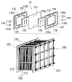
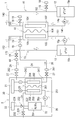
- FIG. 1 is a schematic configuration diagram of a redox flow battery electrolyte regenerating apparatus and a redox flow battery according to Embodiment 1. It is a schematic structure figure showing an example of a cell stack.
- FIG. 2 is a schematic configuration diagram of a redox flow battery electrolyte regenerating apparatus and a redox flow battery according to Embodiment 2.
- Patent Literature 1 discloses an electrolytic solution of an RF battery so that a valence balance of an active material becomes normal by electrochemically changing a valence of an active material in an electrolytic solution using an electrolyte readjusting apparatus. It has been proposed to regenerate the liquid.
- a redox flow battery with an electrolyte readjustment device described in Patent Document 1 has a configuration in which an electrolyte readjustment device is always attached to a redox flow battery unit. Therefore, when installing a plurality of redox flow type batteries, it is necessary to attach an electrolyte readjustment device to each redox flow type battery unit from the beginning, which causes an increase in cost.
- the first electrolytic cell and the positive electrode tank are connected by a piping system, and the positive electrode electrolyte is circulated from the positive electrode tank to the first electrode. It is. Since the positive electrode electrolyte does not flow from the positive electrode tank to the pipe just by connecting the pipe to the positive electrode tank, the configuration described in Patent Literature 1 requires the positive electrode solution between the positive electrode tank and the first electrolytic tank. Requires a dedicated pump to circulate. In the case of the redox flow battery described in Patent Document 1, four pumps are used. In addition, it is necessary to separately provide a connecting portion for connecting a piping system connected to the first electrolytic cell to the positive electrode solution tank. In the case where the connection part is provided in the electrolyte tank for storing the electrolyte, the cost increases.
- an object of the present disclosure is to provide a redox flow battery electrolyte regenerating apparatus that can be attached to and detached from a redox flow battery. Another object of the present disclosure is to provide a redox flow battery including the above-described redox flow battery electrolyte regenerating device. Further, an object of the present disclosure is to provide a method for producing a redox flow battery regenerated electrolyte using the above-described redox flow battery electrolyte regenerating apparatus.
- An apparatus for regenerating an electrolyte for a redox flow battery includes: A regeneration cell having a first electrode, a second electrode, and a diaphragm interposed between the first electrode and the second electrode; A power supply device for supplying a current between the first electrode and the second electrode; A regenerating solution tank for storing a regenerating solution used for regenerating the electrolyte of the redox flow battery, A second circulation pipe for circulating the regeneration liquid from the regeneration liquid tank to the second electrode; A first supply pipe that supplies at least a portion of the electrolyte to the first electrode from a battery pipe that circulates the electrolyte between an electrolyte tank and a battery cell included in the redox flow battery; A first discharge pipe configured to discharge the electrolyte supplied to the first electrode to the battery pipe; A supply-side connection portion for detachably connecting an end of the first supply pipe and the battery pipe; A discharge-side connection portion for detachably connecting an end of the first discharge pipe to the battery pipe
- the regenerating device for an electrolytic solution for an RF battery (hereinafter, may be simply referred to as a “regenerating device”), by providing a supply-side connection portion and a discharge-side connection portion, the first supply pipe and the battery supply pipe can be provided. A first discharge pipe is detachably connected. Therefore, the playback device can be attached to and detached from the RF battery. Therefore, the regenerating device can be attached to the RF battery when the electrolytic solution is regenerated, and the regenerating device can be removed from the RF battery when the electrolytic solution is not regenerated.
- the regenerating device is temporarily attached to the RF battery during maintenance for regenerating the electrolyte, for example, it is not necessary to always attach the regenerating device to the RF battery, and the cost of the RF battery does not increase.
- the regeneration of the electrolytic solution is performed on a plurality of RF batteries in order, it is possible to support a plurality of RF batteries with one regenerating device by attaching a regenerating device to each RF battery in order.
- the first supply pipe and the first discharge pipe are connected to the battery pipe instead of the electrolyte tank of the RF battery, so that the electrolyte is circulated from the battery pipe to the first electrode.
- the battery pipe is usually provided with a pump for circulating the electrolyte between the electrolyte tank and the battery cell.
- the electrolytic solution can be pumped from the battery pipe to the first supply pipe using a pump provided in the battery pipe.
- a pump for pumping the electrolyte from the electrolyte tank to the first supply pipe is separately required.
- the regenerator can eliminate the need for a dedicated pump for circulating the electrolyte between the battery pipe and the first electrode.
- the number of pumps can be reduced as compared with the case where the first supply pipe is connected to the first pump.
- the number of pumps to be driven can be reduced, so that the energy consumed by the pumps may be reduced.
- the first supply pipe and the first discharge pipe are connected to the battery pipe, there is no need to provide a connection portion in the electrolyte tank, and the cost of the electrolyte tank can be reduced.
- the regenerator is attached to the RF battery by connecting each end of the first supply pipe and the first discharge pipe to the battery pipe.
- the playback device operates as follows. While supplying a current between the first electrode and the second electrode by the power supply device, the electrolyte is circulated from the battery pipe to the first electrode via the first supply pipe and the first discharge pipe, and is used for regeneration. The liquid is circulated from the regenerating liquid tank to the second electrode via the second circulation line.
- the electrolytic solution is regenerated so that the valence balance of the active material falls within a normal range.
- the battery capacity of the RF battery can be restored by returning the collapsed valence balance of the electrolyte to a normal range.
- connection point of the first supply pipe to the battery pipe may be located on the downstream side of the battery cell in the battery pipe.
- connection point of the first supply pipe to the battery pipe is located downstream of the battery cell in the battery pipe, the flow rate of the electrolytic solution supplied to the battery cell is maintained. Further, since the connection point of the first supply pipe is located on the downstream side of the battery cell, the electrolyte solution regenerated by the regeneration cell is not directly supplied to the battery cell, and the battery cell is charged and discharged. Influence can be avoided. Therefore, even if the regenerating device regenerates the electrolyte while performing the charging and discharging in the battery cell, the charging and discharging characteristics of the battery cell are hardly affected. Therefore, it is possible to simultaneously regenerate the electrolyte while operating the RF battery without hindering the operation of the RF battery.
- the connection point of the first supply pipe is located on the upstream side of the battery cell in the battery pipe, the electrolytic solution is diverted from the battery pipe to the first electrode, and is supplied to the battery cell.
- the electrolyte flow rate is reduced. Therefore, when regenerating the electrolyte while operating the RF battery, the charging / discharging output of the battery cell may be reduced, or in some cases, the charging / discharging of the battery cell may not be performed. There is a risk of coming.
- components of the regenerating device such as a cell for regeneration, a power supply device, a liquid tank for regeneration, a second circulation pipe, and a first supply pipe and a first discharge pipe are provided in a casing such as a container. It is stored in a lump. Therefore, it is easy to transport the playback device in an assembled state, and if the playback device is transported to the installation location of the RF battery, the installation work of the playback device at the installation site is also easy.
- the supply-side connection portion and the discharge-side connection portion are arranged outside the container, connection between the battery pipe and the first supply pipe and the first discharge pipe is easy.
- the redox flow battery according to the embodiment includes: The apparatus for regenerating the electrolyte for a redox flow battery according to any one of the above (1) to (3) is provided.
- the regenerator is attached by connecting each end of the first supply pipe and the first discharge pipe to the battery pipe, and the electrolyte is circulated from the battery pipe to the first electrode. . Therefore, as described above, a dedicated pump for circulating the electrolyte between the battery pipe and the first electrode becomes unnecessary. Therefore, not only can the number of pumps be reduced, but also the energy consumed by the pumps when regenerating the electrolyte may be reduced.
- the above-mentioned reproducing apparatus can be attached and detached, it can be attached as needed, and can be detached when it becomes unnecessary. Therefore, it is not necessary to attach the reproducing device to the RF battery from the beginning, and the cost of the RF battery does not increase.
- the method for producing a regenerated electrolyte solution for a redox flow battery includes: The first supply pipe and the first discharge pipe of the redox flow battery electrolyte regenerating apparatus according to any one of the above (1) to (3), wherein the first supply pipe and the first discharge pipe are connected to a battery pipe of the redox flow battery.
- the electrolytic solution is circulated from the battery pipe to the first electrode, and the regenerating solution is supplied from the regenerating solution tank to the first electrode.
- a step of adjusting the valence of the active material in the electrolyte by circulating and supplying the active material to the second electrode.
- the manufacturing method uses the regenerator according to the above-described embodiment to manufacture a regenerated electrolyte solution for an RF battery.
- the first supply pipe and the first discharge pipe of the regenerating device are connected to the battery pipe of the RF battery requiring maintenance for regenerating the electrolyte. Then, the electrolytic solution of the RF battery is regenerated while the regenerating device is temporarily attached to the RF battery, and the regenerated electrolytic solution can be manufactured.
- the electrolyte while supplying an electric current between the first electrode and the second electrode, the electrolyte is circulated and supplied from the battery pipe to the first electrode, and the regeneration liquid is supplied from the regeneration liquid tank to the second electrode. Circulating supply.
- the electrolytic solution can be regenerated so that the valence balance of the active material falls within a normal range.
- the RF battery 1 includes a playback device 2.
- the regenerating apparatus 2 includes a regenerating cell 20, a power supply device 21, a regenerating liquid tank 22, a first circulation line 24, and a second circulation line 25.
- One of the features of the regenerating apparatus 2 is that the connection between each end of the first supply pipe 241 and the first discharge pipe 242 constituting the first circulation pipe 24 and the battery pipe 14 of the RF battery 1 is detachable. In that a supply side connection part 261 and a discharge side connection part 262 are provided.
- the basic configuration of the RF battery 1 will be described, and then the configuration of the regenerating apparatus 2 and a method for producing a regenerated electrolyte for an RF battery using the regenerating apparatus 2 will be described.
- the RF battery 1 is typically connected to a power system via an AC / DC converter, and performs charging and discharging with the power system. As shown in FIG. 1, the RF battery 1 includes a battery cell 10, electrolyte tanks 12 and 13, and battery pipes 14 and 15. FIG. 1 shows a state where the playback device 2 is attached to the RF battery 1, but the playback device 2 is not attached to the RF battery 1 in a normal state.
- the battery cell 10 performs charging and discharging.
- the battery cell 10 includes a positive electrode 104, a negative electrode 105, and a diaphragm 101 interposed between the electrodes 104 and 105.
- a positive electrode cell 102 and a negative electrode cell 103 are formed with a diaphragm 101 interposed therebetween.
- the diaphragm 101 is, for example, an ion exchange membrane that transmits hydrogen ions.
- Each of the positive electrode cell 102 and the negative electrode cell 103 has a built-in positive electrode 104 and negative electrode 105.
- Battery pipes 14 and 15 are connected to the battery cell 10 (the positive electrode cell 102 and the negative electrode cell 103). Electrolytes (the positive electrode electrolyte 10p and the negative electrode electrolyte 10n) circulate through the battery pipes 14, 15.
- the battery cell 10 may be configured as a single cell including a single battery cell 10 or may be configured as a multi-cell including a plurality of battery cells 10.
- a form called a cell stack 100 formed by stacking a plurality of battery cells 10 as shown in FIG. 2 is used.
- the cell stack 100 is configured by sandwiching the sub-stack 200 between two end plates 220 from both sides thereof and tightening the end plates 220 on both sides by a tightening mechanism 230 (see the lower diagram in FIG. 2).
- FIG. 2 illustrates an example in which a plurality of substacks 200 are provided.
- the sub-stack 200 has a plurality of cell frames 130, a positive electrode 104, a diaphragm 101, and a negative electrode 105 laminated in this order (see the upper diagram in FIG. 2), and supply / discharge plates 210 are arranged at both ends of the laminated body. Configuration. To the supply / discharge plate 210, supply pipes 141 and 151 and discharge pipes 142 and 152 of the battery pipes 14 and 15 (see FIG. 1) are connected. The number of stacked battery cells 10 in the cell stack 100 can be appropriately selected.
- the cell frame 130 includes a bipolar plate 131 disposed between the positive electrode 104 and the negative electrode 105, and a frame 132 provided around the bipolar plate 131.
- the positive electrode 104 is disposed on one surface of the bipolar plate 131
- the negative electrode 105 is disposed on the other surface of the bipolar plate 131.
- the positive electrode 104 and the negative electrode 105 are housed inside the frame 132 with the bipolar plate 131 interposed therebetween, and one surface side and the other surface side of the adjacent frame body 132 are opposed to each other and abut against each other.
- the positive electrode 104 and the negative electrode 105 are disposed between the bipolar plates 131 of the adjacent cell frames 130 with the diaphragm 101 interposed therebetween, so that one battery cell 10 ( The positive electrode cell 102 and the negative electrode cell 103) are formed.
- the liquid supply manifolds 133 and 134 and the liquid discharge manifolds 135 and 136, the liquid supply slits 133s and 134s, and the liquid discharge slits 135s and 136s are formed in the frame 132 of the cell frame 130.
- the positive electrode electrolyte is supplied from the liquid supply manifold 133 provided below the frame 132 to the positive electrode 104 via the liquid supply slit 133 s formed on one surface side of the frame 132. Then, the liquid is discharged to the drain manifold 135 through a drain slit 135s formed in an upper portion of the frame 132.
- the negative electrode electrolyte is supplied to the negative electrode 105 from a liquid supply manifold 134 provided below the frame 132 through a liquid supply slit 134 s formed on the other surface side of the frame 132.
- the liquid is discharged to the liquid discharge manifold 136 through a liquid discharge slit 136s formed at an upper portion of the liquid discharge manifold.
- the liquid supply manifolds 133 and 134 and the liquid discharge manifolds 135 and 136 are provided so as to penetrate the frame 132, and form a flow path for the electrolyte by stacking the cell frames 130. These flow paths communicate with the supply pipes 141, 151 and the discharge pipes 142, 152 of the battery pipes 14, 15 (see FIG. 1) via the supply / discharge plate 210 (see the lower diagram of FIG. 2), respectively. It is possible to make the electrolyte flow through the cell 10 for use.
- the electrolyte tanks 12 and 13 shown in FIG. 1 store the electrolyte.
- the electrolyte tank 12 is a cathode electrolyte tank that stores the cathode electrolyte 10p.
- the electrolyte tank 13 is a negative electrode electrolyte tank that stores the negative electrode electrolyte 10n.
- the electrolytic solution of the RF battery 1 contains metal ions serving as an active material.
- the positive electrode active material of the positive electrode electrolyte 10p include vanadium ions ( V5 + / V4 + ), manganese ions (Mn3 + / Mn2 + ), iron ions (Fe2 + / Fe3 + ), and the like.
- the negative electrode active material of the negative electrode electrolyte 10n include vanadium ions (V 2+ / V 3+ ), titanium ions (Ti 3+ / Ti 4+ ), and chromium ions (Cr 3+ / Cr 2+ ).
- the positive electrode electrolyte 10p is a sulfuric acid aqueous solution containing V 5+ / V 4+ and the negative electrode electrolyte 10n is a sulfuric acid aqueous solution containing V 2+ / V 3+ .
- the valence balance of the active material (vanadium (V) ion) of the entire electrolytic solution including the positive electrode electrolytic solution and the negative electrode electrolytic solution is adjusted to be close to 3.5. .
- the valence of the active material in the electrolytic solution can be measured by, for example, coulometry, ICP emission spectroscopy, or the like.
- the battery pipes 14 and 15 are pipes for circulating the electrolyte between the electrolyte tanks 12 and 13 and the battery cell 10.
- the battery pipe 14 is a positive electrolyte pipe that circulates the positive electrolyte 10p between the electrolyte tank (positive electrolyte tank) 12 and the battery cell 10 (positive cell 102).
- the battery pipe 15 is a negative electrode electrolyte pipe that circulates the negative electrode electrolyte 10n between the electrolyte tank (negative electrode tank) 13 and the battery cell 10 (negative cell 103). As shown in FIG.
- the cathode electrolyte pipe 14 supplies the cathode electrolyte 10p from the cathode electrolyte tank 12 to the cathode cell 102 (the cathode electrode 104), and supplies the cathode electrolyte 10p to the cathode cell 102 (the cathode electrode 104).
- a discharge pipe 142 for returning the collected cathode electrolyte 10p to the cathode electrolyte tank 12.
- the negative electrode electrolyte pipe 15 includes a supply pipe 151 for sending the negative electrode electrolyte 10n from the negative electrode electrolyte tank 13 to the negative electrode cell 103 (negative electrode 105), and a negative electrode solution supplied to the negative electrode cell 103 (negative electrode 105).
- the supply pipes 141 and 151 of the battery pipes 14 and 15 are provided with pumps 14p and 15p for pumping the electrolyte.
- the battery pipe (positive electrode electrolyte pipe) 14 has a first branch port 161 and a second branch port 162 branched from the battery pipe 14.
- a first branch port 161 and a second branch port 162 are provided on the downstream side of the battery cell 10 in the battery pipe 14, that is, on the discharge pipe 142.
- the second branch port 162 is provided downstream of the first branch port 161.
- the first branch port 161 and the second branch port 162 have a connection port 18 and a valve 19.
- connection ports 18 of the first branch port 161 and the second branch port 162 are connected to a supply-side connection part 261 and a discharge-side connection part 262 of a first supply pipe 241 and a first discharge pipe 242 of the regenerating device 2 described later. Is done. In a state where the reproducing device 2 is not attached to the RF battery 1, that is, in a state where the supply-side connection portion 261 and the discharge-side connection portion 262 are not connected to the respective connection ports 18 of the first branch port 161 and the second branch port 162. , Valve 19 is closed.
- the first branch port 171 and the second branch port are also provided on the anode electrolyte pipe 15, similarly to the cathode electrolyte pipe 14, on the downstream side of the battery cell 10, that is, on the discharge pipe 152.
- a port 172 is provided.
- the second branch port 172 is provided downstream of the first branch port 171.
- the first branch port 171 and the second branch port 172 have a connection port 18 and a valve 19, like the first branch port 161 and the second branch port 162.
- the regenerating device 2 is attached to the RF battery 1 and regenerates the electrolyte of the RF battery 1.
- the configuration of the playback device 2 will be described in detail.
- the regeneration cell 20 regenerates the electrolyte by adjusting the valence of the active material (V 5+ / V 4+ ) in the electrolyte (in this example, the positive electrode electrolyte 10p).
- the playback cell 20 has the same basic structure as the battery cell 10.
- the reproducing cell 20 has a first electrode 204, a second electrode 205, and a diaphragm 201 interposed between the electrodes 204 and 205.
- a first cell 202 and a second cell 203 are formed with a diaphragm 201 interposed therebetween.
- the diaphragm 201 is, for example, an ion exchange membrane.
- the first electrode 202 and the second electrode 205 are built in the first cell 202 and the second cell 203.
- the first circulation line 24 and the second circulation line 25 are connected to the regeneration cell 20 (the first cell 202 and the second cell 203).
- the electrolyte (the positive electrode electrolyte 10p) circulates through the first circulation line 24 to the first cell 202, and the regeneration solution 20r circulates through the second circulation line 25 to the second cell 203.
- the power supply device 21 is a DC power supply that is connected to the first electrode 204 and the second electrode 205 and that supplies a current (applies a voltage) between the first electrode 204 and the second electrode 205.
- the power supply 21 has a positive terminal and a negative terminal.
- FIG. 1 illustrates a case where the first electrode 204 is connected to a negative terminal of the power supply device 21 to be a negative electrode, and the second electrode 205 is connected to a positive terminal of the power supply device 21 to be a positive electrode.
- the power supply device 21 can switch between the + terminal and the ⁇ terminal, and the polarity of the first electrode 204 and the second electrode 205 can be reversed by the switching operation.
- the regeneration liquid tank 22 stores the regeneration liquid 20r.
- the regenerating solution 20r is a solution used for regenerating the electrolytic solution of the RF battery 1, and an electrolytic solution that causes an electrolytic reaction in the regenerating cell 20, such as an aqueous sulfuric acid solution, an aqueous hydrochloric acid solution, or an aqueous formic acid solution, can be used.
- an electrolytic solution that causes an electrolytic reaction in the regenerating cell 20 such as an aqueous sulfuric acid solution, an aqueous hydrochloric acid solution, or an aqueous formic acid solution, can be used.
- As the regeneration liquid 20r a liquid that electrolyzes water is preferable.
- the regeneration liquid 20r is a dilute sulfuric acid (H 2 SO 4 ) aqueous solution.
- the gas generated at the second electrode 205 by the electrolytic reaction during regeneration of the electrolytic solution of the RF battery 1 is mainly hydrogen (H 2 ) or oxygen (O 2 ). . Therefore, the gas generated by the electrolytic reaction is easily processed, and can be released to the atmosphere as it is.
- the regenerating solution 20r is preferably the same type of electrolyte as the base electrolyte used for the solvent of the active material in the electrolyte of the RF battery 1.
- the regeneration liquid 20r is also a sulfuric acid aqueous solution.
- the regenerating solution 20r is a sulfuric acid aqueous solution of the same type as the solvent of the electrolytic solution of the RF battery 1, the influence is small even if the solution 20r enters the electrolytic solution of the RF battery 1 through the diaphragm 201.
- a gas vent pipe 221 for discharging gas in the regeneration liquid tank 22 to exhaust gas generated by the electrolytic reaction is provided.
- the gas vent pipe 221 is provided with a gas vent valve 222.
- the gas vent valve 222 is opened, and the gas is released from the opening.
- a supply tank 23 is provided to supply the reduced amount.
- the replenishing tank 23 is connected to the regenerating liquid tank 22 via a replenishing pipe 231, and the reduced regenerating liquid 20 r is supplied from the replenishing tank 23 to the regenerating liquid tank 22.
- the supply pipe 231 is provided with a valve 232, and the supply amount can be adjusted by the valve 232.
- the regeneration liquid 20r is an aqueous solution of sulfuric acid and a gas is generated by the electrolytic reaction
- the amount of water decreases.
- water is stored in the supply tank 23, and water is supplied from the supply tank 23 to the regeneration liquid tank 22.
- the first circulation pipe 24 is a pipe that circulates and supplies the electrolyte (the positive electrode electrolyte 10p) from the battery pipe (the positive electrode electrolyte pipe) 14 to the first cell 202 (the first electrode 204).
- the first circulation pipe 24 includes a first supply pipe 241 for supplying at least a part of the electrolytic solution from the battery pipe 14 to the first electrode 204, and an electrolytic solution supplied to the first electrode 204.
- a first discharge pipe 242 for discharging the liquid to the battery pipe 14.
- the first circulation line 24 is not provided with a pump for pumping the electrolyte.
- each connection point of the first supply pipe 241 and the first discharge pipe 242 to the battery pipe 14 is located on the downstream side of the battery cell 10 in the battery pipe 14, that is, at the discharge pipe 142. Is located downstream of the connection point of the first supply pipe 241.
- the electrolyte flowing through the battery pipe 14 (discharge pipe 142) is sent from the first branch port 161 to the first supply pipe 241, and the electrolyte discharged from the first discharge pipe 242 is transferred to the second branch port 162. Is returned to the battery pipe 14 (discharge pipe 142).
- Each end of the first supply pipe 241 and the first discharge pipe 242 is detachably connected to the battery pipe 14 (the first branch port 161 and the second branch port 162) and the supply-side connection part 261 and the discharge-side connection part 262. Connected. Therefore, the playback device 2 can be attached to and detached from the RF battery 1.
- a well-known flange adapter or the like can be used for the supply side connection portion 261 and the discharge side connection portion 262.
- a connection pipe 28 such as a hose is provided between the supply-side connection portion 261 and the discharge-side connection portion 262 and the connection ports 18 of the first branch port 161 and the second branch port 162. Are connected.
- the supply side connection part 261 and the discharge side connection part 262 are connected to each connection port 18 via the connection pipe 28.
- the valve 27 is provided at the supply-side connection part 261 and the discharge-side connection part 262. In a state where the reproducing device 2 is not attached to the RF battery 1, that is, in a state where the supply side connection part 261 and the discharge side connection part 262 are not connected to the first branch port 161 and the second branch port 162, the valve 27 is closed. Have been. When the valve 19 and the valve 27 are opened in a state where the supply-side connection portion 261 and the discharge-side connection portion 262 are connected to the respective connection ports 18 of the first branch port 161 and the second branch port 162, the first branch port 161 and the second branch port 162 are connected. The first supply pipe 241 is in communication, and the second branch port 162 and the first discharge pipe 242 are in communication.
- the second circulation pipeline 25 is a pipeline that circulates and supplies the regeneration liquid 20r from the regeneration liquid tank 22 to the second cell 203 (second electrode 205).
- the second circulation pipe 25 includes a second supply pipe 251 for sending the regeneration liquid 20 r from the regeneration liquid tank 22 to the second electrode 205, and a regeneration liquid supplied to the second electrode 205.
- a second discharge pipe 252 that returns 20r to the regeneration liquid tank 22.
- the second supply pipe 251 is provided with a pump 25p for pumping the regeneration liquid 20r.
- the positive electrode electrolyte 10p is circulated and supplied from the discharge pipe 142 of the positive electrode pipe 14 to the first cell 202 (first electrode 204) of the regeneration cell 20 via the first circulation pipe 24.
- the regeneration liquid 20r is circulated and supplied from the regeneration liquid tank 22 to the second cell 203 (second electrode 205) of the regeneration cell 20 via the second circulation pipe 25.
- the first supply pipe 241 of the first circulation line 24 is connected to the lower part of the first cell 202, and the positive electrode electrolyte 10p is supplied from below the first electrode 204.
- the first discharge pipe 242 of the first circulation line 24 is connected to the upper part of the first cell 202, and the positive electrode electrolyte 10p supplied to the first electrode 204 is discharged from above the first electrode 204.
- the second supply pipe 251 of the second circulation pipe 25 is connected to the lower part of the second cell 203, and the regeneration liquid 20r is supplied from below the second electrode 205.
- the second discharge pipe 252 of the second circulation pipe 25 is connected to the upper part of the second cell 203, and the regeneration liquid 20r supplied to the second electrode 205 is discharged from above the second electrode 205.
- the flow direction of the positive electrode electrolyte 10p flowing in the first cell 202 matches the flow direction of the regeneration liquid 20r flowing in the second cell 203.
- the respective liquids can be circulated stably. This is because a local pressure difference between the first cell 202 and the second cell 203 is reduced.
- the flow direction of each liquid supplied to each of the electrodes 204 and 205 may be different.
- the first supply pipe 241 is connected to the upper part of the first cell 202 to supply the positive electrode electrolyte 10p from above the first electrode 204, and the first discharge pipe 242 is connected to the lower part of the first cell 202 to form the positive electrode.
- the electrolytic solution 10p may be discharged from below the first electrode 204.
- the regenerating apparatus 2 illustrated in FIG. 1 includes a regenerating cell 20, a power supply 21, a regenerating liquid tank 22, a first circulation line 24 (a first supply pipe 241 and a first discharge pipe 242), A container 30 for storing components such as a two-circulation conduit 25 is provided.
- the supply tank 23 is also stored in the container 30.
- the supply side connection part 261 and the discharge side connection part 262 are arranged outside the container 30. Therefore, connection of the supply side connection part 261 and the discharge side connection part 262 to the battery pipe 14 (the first branch port 161 and the second branch port 162) is facilitated. Further, the opening of the gas vent pipe 221 is provided outside the container 30, and the gas in the regeneration liquid tank 22 is released outside the container 30.
- the components of the playback device 2 are collectively stored in the container 30, and the playback device 2 is stored in an assembled state. Since the playback device 2 is stored in the container 30, the transport of the playback device 2 is easy, and the installation work of the playback device 2 is also easy.
- the container 30 is typically a dry container used for transporting general cargo.
- the size of the container 30 may be appropriately selected according to the size of the playback device 2 or the like.
- the container 30 includes, for example, an international sea freight container conforming to an ISO standard (eg, ISO $ 1496-1: 2013 etc.), specifically, a 20-foot container, a 40-foot container, a 45-foot container, and a 20-foot high cube. Containers, 40 foot high cube containers, 45 foot high cube containers and the like can be used.
- the electrolytic solution of the RF battery 1 is regenerated using the regenerating device 2 to produce a regenerated electrolytic solution for the RF battery (hereinafter, may be referred to as “regenerated electrolytic solution”).
- the valence of the active material in the electrolyte (the positive electrode electrolyte 10p and the negative electrode electrolyte 10n) is measured during maintenance of the RF battery 1, and the valence balance of the active material in the entire electrolyte is normal. It is carried out when it is out of the range.
- branch ports 161, 162, 171, and 172 are provided in the battery pipes 14 and 15. By opening the valve 19, the electrolyte in each of the battery pipes 14, 15 can be easily extracted.
- V 5+ / V 4+ is used for the positive electrode active material
- V 2+ / V 3+ is used for the negative electrode active material
- the valence balance of the active material falls within a range from 3.4 valences to 3.6 valences. Range.
- the valence balance of the active material shifts to the positive electrode side, and gradually shifts from the initial 3.5 valence so as to increase.
- oxygen (O 2 ) is generated at the positive electrode 104 due to a side reaction
- V 4+ becomes excessive and V 5+ becomes insufficient in the positive electrode electrolyte 10p.
- the valence balance of the active material shifts to the negative electrode side, and gradually shifts from the initial 3.5 valence to a smaller value.
- the regenerating device 2 is transported to the installation location of the RF battery 1 where the electrolytic solution is to be regenerated, and the regeneration device 2 is transferred to the RF battery 1. Attach.
- the playback device 2 since the playback device 2 is stored in the container 30, the transport of the playback device 2 is easy, and the installation work of the playback device 2 on site is also easy.
- the attachment of the regenerating device 2 to the RF battery 1 is performed by connecting the first supply pipe 241 and the first discharge pipe 242 to the battery pipe (positive electrolyte pipe) 14 of the RF battery 1.
- the supply side connection part 261 and the discharge side connection part 262 of the first supply pipe 241 and the first discharge pipe 242 are connected to the first branch port 161 and the second branch port of the battery pipe 14 via the connection pipe 28.
- Each connection port 18 of the port 162 is connected.
- the reproducing device 2 is attached to the RF battery 1.
- the valves 19 and 27 are opened.
- the method for producing a regenerated electrolytic solution includes the following electrolytic solution regenerating step.
- the active material in the electrolytic solution is reproduced by the regeneration device 2 (regeneration cell 20) in a state where the first supply pipe 241 and the first discharge pipe 242 of the regeneration device 2 are connected to the battery pipe 14 of the RF battery 1.
- This is the step of adjusting the valency. Specifically, while supplying an electric current between the first electrode 204 and the second electrode 205, the electrolyte (the positive electrode electrolyte 10p) is circulated and supplied from the battery pipe 14 to the first electrode 204, and at the same time, used for regeneration.
- the liquid 20r is circulated and supplied from the regeneration liquid tank 22 to the second electrode 205.
- the current flowing between the first electrode 204 and the second electrode 205 may be set within a range where an electrolytic reaction occurs.
- the positive electrode electrolyte 10p is circulated and supplied from the battery pipe 14 to the first electrode 204, and the regeneration liquid 20r is circulated and supplied from the regeneration liquid tank 22 to the second electrode 205. Then, a current is applied (voltage is applied) between the first electrode 204 and the second electrode 205 by the power supply device 21 to make the first electrode 204 a negative electrode and the second electrode 205 a positive electrode (see FIG. 1). .
- the electrolytic reaction in the regeneration cell 20 is as follows.
- the positive electrode electrolyte 10p supplied from the battery pipe 14 to the first electrode 204 via the first supply pipe 241 undergoes a reaction of [V 5+ + e ⁇ ⁇ V 4+ ] at the first electrode 204 of the negative electrode, and the positive electrode electrolyte V 5+ in the liquid 10p is changed to V 4+. Thereafter, the positive electrode electrolyte 10p is returned to the battery pipe 14 via the first discharge pipe 242.
- the electrolyte is regenerated, and the regenerated electrolytic solution is regenerated. Produce a liquid.
- the regenerating liquid 20r supplied from the regenerating liquid tank 22 to the second electrode 205 via the second supply pipe 251 receives the [2H 2 O ⁇ O 2 + 4H + + 4e ⁇ ] at the second electrode 205 of the positive electrode. A reaction occurs, and oxygen (O 2 ) is generated. Thereafter, the regeneration liquid 20r containing oxygen gas is returned to the regeneration liquid tank 22 via the second discharge pipe 252. The oxygen gas is discharged out of the regenerating liquid tank 22 through the gas vent pipe 221.
- the + terminal and the ⁇ terminal of the power supply device 21 are switched to make the first electrode 204 a positive electrode and the second electrode 205 a negative electrode.
- the electrolytic reaction in the regeneration cell 20 is as follows.
- the positive electrode electrolyte 10p supplied from the battery pipe 14 to the first electrode 204 via the first supply pipe 241 causes a reaction of [V 4+ ⁇ V 5+ + e ⁇ ] at the first electrode 204 of the positive electrode, and the positive electrode electrolyte V 4+ in the liquid 10p is changed to V 5+ . Thereafter, the positive electrode electrolyte 10p is returned to the battery pipe 14 via the first discharge pipe 242.
- the electrolyte is regenerated, and the regenerated electrolytic solution is regenerated. Produce a liquid.
- the regenerating liquid 20r supplied from the regenerating liquid tank 22 to the second electrode 205 via the second supply pipe 251 causes a reaction of [2H + + 2e ⁇ ⁇ H 2 ] at the negative electrode second electrode 205. , And hydrogen (H 2 ) is generated. Thereafter, the regeneration liquid 20r containing hydrogen gas is returned to the regeneration liquid tank 22 via the second discharge pipe 252. The hydrogen gas is discharged to the outside of the regenerating liquid tank 22 through the gas vent pipe 221.
- the supply-side connection part 261 and the discharge-side connection part 262 of the first supply pipe 241 and the first discharge pipe 242 are provided on the discharge pipe 152 of the negative electrode electrolyte pipe 15.
- the connection ports 18 of the first branch port 171 and the second branch port 172 are connected.
- the negative electrode electrolyte 10n flowing through the negative electrode electrolyte pipe 15 (discharge pipe 152) is sent from the first branch port 171 to the first supply pipe 241 and the negative electrode electrolyte 10n discharged from the first discharge pipe 242 is discharged.
- the liquid is returned from the second branch port 172 to the negative electrode electrolyte pipe 15 (discharge pipe 152). Therefore, the negative electrode electrolyte 10 n is circulated and supplied from the discharge pipe 152 of the negative electrode electrolyte pipe 15 to the first cell 202 (first electrode 204) of the regeneration cell 20 via the first circulation pipe 24.
- the negative electrode electrolyte 10n is circulated and supplied from the negative electrode electrolyte pipe 15 to the first electrode 204, and the valence of the active material (V 2+ / V 3+ ) in the negative electrode electrolyte 10n is adjusted. This is different from the first embodiment.
- the negative electrode electrolyte 10n is circulated and supplied from the negative electrode electrolyte pipe 15 to the first electrode 204, and the regeneration liquid 20r is circulated and supplied from the regeneration liquid tank 22 to the second electrode 205. Then, a current is applied (voltage is applied) between the first electrode 204 and the second electrode 205 by the power supply device 21 to make the first electrode 204 a negative electrode and the second electrode 205 a positive electrode (see FIG. 3). .
- the electrolytic reaction in the regeneration cell 20 is as follows.
- the negative electrode electrolyte 10n supplied from the negative electrode electrolyte pipe 15 to the first electrode 204 via the first supply pipe 241 causes a reaction of [V 3+ + e ⁇ ⁇ V 2+ ] at the first electrode 204 of the negative electrode, V 3+ in the electrolyte 10n is changed to V 2+ . Thereafter, the negative electrode electrolyte 10n is returned to the negative electrode electrolyte pipe 15 via the first discharge pipe 242.
- the regenerating liquid 20r supplied from the regenerating liquid tank 22 to the second electrode 205 via the second supply pipe 251 receives the [2H 2 O ⁇ O 2 + 4H + + 4e ⁇ ] at the second electrode 205 of the positive electrode. A reaction occurs, and oxygen (O 2 ) is generated. Thereafter, the regeneration liquid 20r containing oxygen gas is returned to the regeneration liquid tank 22 via the second discharge pipe 252. The oxygen gas is discharged out of the regenerating liquid tank 22 through the gas vent pipe 221.
- the + terminal and the ⁇ terminal of the power supply device 21 are switched to make the first electrode 204 a positive electrode and the second electrode 205 a negative electrode.
- the electrolytic reaction in the regeneration cell 20 is as follows.
- a reaction of [V 2+ ⁇ V 3+ + e ⁇ ] occurs at the first electrode 204 of the positive electrode.
- V2 + in the electrolyte 10n is changed to V3 + .
- the negative electrode electrolyte 10n is returned to the negative electrode electrolyte pipe 15 via the first discharge pipe 242.
- the regenerating liquid 20r supplied from the regenerating liquid tank 22 to the second electrode 205 via the second supply pipe 251 causes a reaction of [2H + + 2e ⁇ ⁇ H 2 ] at the negative electrode second electrode 205. , And hydrogen (H 2 ) is generated. Thereafter, the regeneration liquid 20r containing hydrogen gas is returned to the regeneration liquid tank 22 via the second discharge pipe 252. The hydrogen gas is discharged to the outside of the regenerating liquid tank 22 through the gas vent pipe 221.
- the playback device 2 and the RF battery 1 of the first and second embodiments have the following effects.
- the regenerating device 2 can be attached to and detached from the RF battery 1, it can be attached to the RF battery 1 when regenerating the electrolytic solution, and can be detached from the RF battery 1 when not regenerating the electrolytic solution. it can. Since the playback device 2 is temporarily attached, for example, during maintenance of the RF battery 1, it is not necessary to always attach the playback device 2 to the RF battery 1, and the cost of the RF battery 1 does not increase.
- the battery pipe 14 (or 15p) is used by using the pump 14p (or 15p).
- the electrolytic solution can be circulated and supplied to the first electrode 204. Therefore, as compared with the case where the first supply pipe 241 and the first discharge pipe 242 are connected to the electrolyte tank 12 (or 13), not only the number of pumps can be reduced, but also In some cases, the energy consumed by the pump when regenerating the liquid can be reduced.
- connection point of the first supply pipe 241 to the battery pipe 14 (or 15) is located on the downstream side of the battery cell 10
- the regeneration of the electrolytic solution is performed by the regeneration cell 20 while charging and discharging the battery cell 10. Is performed, the flow rate of the electrolytic solution supplied to the battery cell 10 can be maintained.
- the electrolytic solution regenerated in the regeneration cell 20 is used for charging and discharging the battery cell 10. Influence can be avoided. Therefore, it is possible to simultaneously regenerate the electrolyte while operating the RF battery 1 without hindering the operation of the RF battery 1.
- the provision of the container 30 for accommodating the components of the reproducing apparatus 2 facilitates the transport of the reproducing apparatus 2 and the installation work of the reproducing apparatus 2. Further, since the supply side connection part 261 and the discharge side connection part 262 are arranged outside the container 30, the connection between the battery pipe 14 (or 15) and the first supply pipe 241 and the first discharge pipe 242 is easy. It is.
- the first supply pipe 241 and the first discharge pipe 242 of the regenerator 2 are connected to the battery pipe 14 (or 15) of the RF battery 1.
- the electrolytic solution of the RF battery 1 is regenerated while the regenerating device 2 is temporarily attached to the RF battery 1.
- a regenerated electrolytic solution for the RF battery can be manufactured.
- Redox flow battery (RF battery) DESCRIPTION OF SYMBOLS 10 Battery cell 101 Diaphragm 102 Positive cell 103 Negative cell 104 Positive electrode 105 Negative electrode 12 Electrolyte tank (positive electrolyte tank) 13 Electrolyte tank (negative electrode electrolyte tank) 14 Battery Piping (Positive Electrolyte Piping) 15 Battery piping (negative electrode electrolyte piping) 141, 151 supply pipe 142, 152 discharge pipe 14p, 15p pump 161, 171 first branch port 162, 172 second branch port 18 connection port 19 valve 100 cell stack 130 cell frame 131 bipolar plate 132 frame 133, 134 liquid supply Manifold 135, 136 Drainage manifold 133s, 134s Liquid supply slit 135s, 136s Liquid discharge slit 200 Substack 210 Supply / discharge plate 220 End plate 230 Tightening mechanism 2 Redox flow battery electrolyte regeneration device 20 Regeneration cell 201 Separator 202 1st cell 203
Landscapes
- Life Sciences & Earth Sciences (AREA)
- Sustainable Development (AREA)
- Engineering & Computer Science (AREA)
- Manufacturing & Machinery (AREA)
- Sustainable Energy (AREA)
- Chemical & Material Sciences (AREA)
- Chemical Kinetics & Catalysis (AREA)
- Electrochemistry (AREA)
- General Chemical & Material Sciences (AREA)
- Fuel Cell (AREA)
Abstract
第1電極と、第2電極と、前記第1電極と前記第2電極との間に介在される隔膜とを有する再生用セルと、前記第1電極と前記第2電極との間に電流を通電する電源装置と、レドックスフロー電池の電解液の再生に用いる再生用液を貯留する再生用液タンクと、前記再生用液を前記再生用液タンクから前記第2電極に循環供給する第2循環管路と、前記レドックスフロー電池に備える電解液タンクと電池用セルとの間で前記電解液を循環させる電池用配管から少なくとも一部の前記電解液を前記第1電極に供給する第1供給管と、前記第1電極に供給された前記電解液を前記電池用配管に排出する第1排出管と、前記第1供給管の端部と前記電池用配管との接続を着脱自在にする供給側接続部と、前記第1排出管の端部と前記電池用配管との接続を着脱自在にする排出側接続部と、を備えるレドックスフロー電池用電解液の再生装置。
Description
本開示は、レドックスフロー電池用電解液の再生装置、レドックスフロー電池、及びレドックスフロー電池用再生電解液の製造方法に関する。
レドックスフロー電池(以下、「RF電池」と呼ぶ場合がある)は、正極電極及び負極電極を内蔵するセルと、活物質を含む電解液を貯留するタンクとを備え、電解液をタンクとセルとの間で循環させることで、電解液中の活物質の価数変化により充放電を行う蓄電池である。電解液には、代表的には、酸化還元により価数が変化する金属イオンを活物質として含む水溶液が使用されている。例えば、正極活物質に鉄イオン(Fe2+/Fe3+)、負極活物質にクロムイオン(Cr3+/Cr2+)を用いる鉄-クロム系レドックスフロー電池、正極及び負極の活物質にバナジウムイオン(正極側:V5+/V4+、負極側:V2+/V3+)を用いるバナジウム系レドックスフロー電池が知られている。
特許文献1には、電解液再調整装置と、レドックスフロー型電池部とを備える電解液再調整装置付レドックスフロー型電池が記載されている(特許文献1の図1参照)。電解液再調整装置は、第1の電解槽内に収容された第1の電極と、第2の電解槽内に収容された第2の電極と、正極電解液再調整液を貯蔵する正極電解液再調整液槽とを備える。レドックスフロー型電池部は、電池反応セルと、正極液タンク及び負極液タンクとを備える。特許文献1に記載された電解液再調整装置付レドックスフロー型電池では、正極液タンクと第1の電解槽との間で正極電解液を流通循環するための配管系と、正極電解液再調整液槽と第2の電解槽との間で正極電解液再調整液を流通循環するための配管系とを備える。そして、正極電解液を第1の電極に供給すると共に、正極電解液再調整液を第2の電極に供給し、外部電源(直流電源)により第1の電極と第2の電極との間に通電を行い、正極電解液を再調整する(活物質の価数を変える)。
本開示のレドックスフロー電池用電解液の再生装置は、
第1電極と、第2電極と、前記第1電極と前記第2電極との間に介在される隔膜とを有する再生用セルと、
前記第1電極と前記第2電極との間に電流を通電する電源装置と、
レドックスフロー電池の電解液の再生に用いる再生用液を貯留する再生用液タンクと、
前記再生用液を前記再生用液タンクから前記第2電極に循環供給する第2循環管路と、
前記レドックスフロー電池に備える電解液タンクと電池用セルとの間で前記電解液を循環させる電池用配管から少なくとも一部の前記電解液を前記第1電極に供給する第1供給管と、
前記第1電極に供給された前記電解液を前記電池用配管に排出する第1排出管と、
前記第1供給管の端部と前記電池用配管との接続を着脱自在にする供給側接続部と、
前記第1排出管の端部と前記電池用配管との接続を着脱自在にする排出側接続部と、を備える。
第1電極と、第2電極と、前記第1電極と前記第2電極との間に介在される隔膜とを有する再生用セルと、
前記第1電極と前記第2電極との間に電流を通電する電源装置と、
レドックスフロー電池の電解液の再生に用いる再生用液を貯留する再生用液タンクと、
前記再生用液を前記再生用液タンクから前記第2電極に循環供給する第2循環管路と、
前記レドックスフロー電池に備える電解液タンクと電池用セルとの間で前記電解液を循環させる電池用配管から少なくとも一部の前記電解液を前記第1電極に供給する第1供給管と、
前記第1電極に供給された前記電解液を前記電池用配管に排出する第1排出管と、
前記第1供給管の端部と前記電池用配管との接続を着脱自在にする供給側接続部と、
前記第1排出管の端部と前記電池用配管との接続を着脱自在にする排出側接続部と、を備える。
本開示のレドックスフロー電池は、
上記本開示のレドックスフロー電池用電解液の再生装置を備える。
上記本開示のレドックスフロー電池用電解液の再生装置を備える。
本開示のレドックスフロー電池用再生電解液の製造方法は、
上記本開示のレドックスフロー電池用電解液の再生装置の前記第1供給管及び前記第1排出管を前記レドックスフロー電池の電池用配管に接続した状態において、
前記第1電極と前記第2電極との間に電流を通電しながら、前記電解液を前記電池用配管から前記第1電極に循環供給すると共に、前記再生用液を前記再生用液タンクから前記第2電極に循環供給することにより、前記電解液中の活物質の価数を調整する工程を備える。
上記本開示のレドックスフロー電池用電解液の再生装置の前記第1供給管及び前記第1排出管を前記レドックスフロー電池の電池用配管に接続した状態において、
前記第1電極と前記第2電極との間に電流を通電しながら、前記電解液を前記電池用配管から前記第1電極に循環供給すると共に、前記再生用液を前記再生用液タンクから前記第2電極に循環供給することにより、前記電解液中の活物質の価数を調整する工程を備える。
[本開示が解決しようとする課題]
RF電池では、充放電を繰り返し行うと、セル内で起こる副反応や、空気中の酸素による酸化によって、電池反応を担う電解液中の活物質の価数が変化することがある。よって、RF電池では、電池反応による可逆的な変化の範囲から徐々にずれていく場合がある。具体的には、電池反応以外の副反応や酸化により、正極電解液と負極電解液における活物質の酸化還元ペア(例えばバナジウム系RF電池の場合、V4+/V3+又はV5+/V2+)のうち、一方が過剰、他方が不足する状態になり、電解液全体の活物質の価数バランスが崩れる場合がある。バナジウム系RF電池であれば、副反応により負極電極で水素(H2)が発生したり、負極電解液中の活物質が酸化したりした場合は、正極電解液では、上記酸化還元ペアのうち、V5+が過剰となる。逆に言えば、正極電解液中のV4+が不足する。一方で、副反応により正極電極で酸素(O2)が発生した場合は、正極電解液では、V4+が過剰となり、V5+が不足する。このように活物質の価数バランスが崩れると、酸化還元ペアの絶対量が減少することになる。そのため、電池容量の低下を招いたりするなど、電池性能に悪影響を及ぼすことがある。
RF電池では、充放電を繰り返し行うと、セル内で起こる副反応や、空気中の酸素による酸化によって、電池反応を担う電解液中の活物質の価数が変化することがある。よって、RF電池では、電池反応による可逆的な変化の範囲から徐々にずれていく場合がある。具体的には、電池反応以外の副反応や酸化により、正極電解液と負極電解液における活物質の酸化還元ペア(例えばバナジウム系RF電池の場合、V4+/V3+又はV5+/V2+)のうち、一方が過剰、他方が不足する状態になり、電解液全体の活物質の価数バランスが崩れる場合がある。バナジウム系RF電池であれば、副反応により負極電極で水素(H2)が発生したり、負極電解液中の活物質が酸化したりした場合は、正極電解液では、上記酸化還元ペアのうち、V5+が過剰となる。逆に言えば、正極電解液中のV4+が不足する。一方で、副反応により正極電極で酸素(O2)が発生した場合は、正極電解液では、V4+が過剰となり、V5+が不足する。このように活物質の価数バランスが崩れると、酸化還元ペアの絶対量が減少することになる。そのため、電池容量の低下を招いたりするなど、電池性能に悪影響を及ぼすことがある。
特許文献1には、電解液再調整装置を用いて、電気化学的に電解液中の活物質の価数を変えることにより、活物質の価数バランスが正常となるように、RF電池の電解液を再生することが提案されている。
特許文献1に記載された電解液再調整装置付レドックスフロー型電池では、レドックスフロー型電池部に電解液再調整装置が常時取り付けられた構成である。そのため、複数のレドックスフロー型電池を設置する場合は、個々のレドックスフロー型電池部に電解液再調整装置を最初から取り付ける必要があり、コストの増加を招く。
また、特許文献1に記載された電解液再調整装置では、第1の電解槽と正極液タンクとが配管系により連結され、正極液タンクから正極電解液を第1の電極に循環供給する構成である。正極液タンクに配管を接続しただけでは、正極液タンクから配管に正極電解液が流れないため、特許文献1に記載の構成では、正極液タンクと第1の電解槽との間で正極電解液を循環させるための専用のポンプが必要である。特許文献1に記載されたレドックスフロー型電池の場合、4つのポンプが使用されている。また、正極液タンクに、第1の電解槽と連結する配管系を接続するための接続部を別途設ける必要がある。電解液を貯留する電解液タンクに接続部を設ける場合、コスト高になる。
そこで、本開示は、レドックスフロー電池に対して取り付け取り外し可能であるレドックスフロー電池用電解液の再生装置を提供することを目的の一つとする。また、本開示は、上記レドックスフロー電池用電解液の再生装置を備えるレドックスフロー電池を提供することを目的の一つとする。更に、本開示は、上記レドックスフロー電池用電解液の再生装置を用いたレドックスフロー電池用再生電解液の製造方法を提供することを目的の一つとする。
[本開示の効果]
本開示によれば、レドックスフロー電池に対して取り付け取り外し可能であるレドックスフロー電池用電解液の再生装置を提供できる。また、本開示によれば、レドックスフロー電池用電解液の再生装置を取り外し可能に備えるレドックスフロー電池を提供できる。更に、本開示によれば、レドックスフロー電池にレドックスフロー電池用電解液の再生装置を取り付けて、レドックスフロー電池の電解液を再生するレドックスフロー電池用再生電解液の製造方法を提供できる。
本開示によれば、レドックスフロー電池に対して取り付け取り外し可能であるレドックスフロー電池用電解液の再生装置を提供できる。また、本開示によれば、レドックスフロー電池用電解液の再生装置を取り外し可能に備えるレドックスフロー電池を提供できる。更に、本開示によれば、レドックスフロー電池にレドックスフロー電池用電解液の再生装置を取り付けて、レドックスフロー電池の電解液を再生するレドックスフロー電池用再生電解液の製造方法を提供できる。
[本開示の実施形態の説明]
最初に本開示の実施形態の内容を列記して説明する。
最初に本開示の実施形態の内容を列記して説明する。
(1)実施形態に係るレドックスフロー電池用電解液の再生装置は、
第1電極と、第2電極と、前記第1電極と前記第2電極との間に介在される隔膜とを有する再生用セルと、
前記第1電極と前記第2電極との間に電流を通電する電源装置と、
レドックスフロー電池の電解液の再生に用いる再生用液を貯留する再生用液タンクと、
前記再生用液を前記再生用液タンクから前記第2電極に循環供給する第2循環管路と、
前記レドックスフロー電池に備える電解液タンクと電池用セルとの間で前記電解液を循環させる電池用配管から少なくとも一部の前記電解液を前記第1電極に供給する第1供給管と、
前記第1電極に供給された前記電解液を前記電池用配管に排出する第1排出管と、
前記第1供給管の端部と前記電池用配管との接続を着脱自在にする供給側接続部と、
前記第1排出管の端部と前記電池用配管との接続を着脱自在にする排出側接続部と、を備える。
第1電極と、第2電極と、前記第1電極と前記第2電極との間に介在される隔膜とを有する再生用セルと、
前記第1電極と前記第2電極との間に電流を通電する電源装置と、
レドックスフロー電池の電解液の再生に用いる再生用液を貯留する再生用液タンクと、
前記再生用液を前記再生用液タンクから前記第2電極に循環供給する第2循環管路と、
前記レドックスフロー電池に備える電解液タンクと電池用セルとの間で前記電解液を循環させる電池用配管から少なくとも一部の前記電解液を前記第1電極に供給する第1供給管と、
前記第1電極に供給された前記電解液を前記電池用配管に排出する第1排出管と、
前記第1供給管の端部と前記電池用配管との接続を着脱自在にする供給側接続部と、
前記第1排出管の端部と前記電池用配管との接続を着脱自在にする排出側接続部と、を備える。
上記RF電池用電解液の再生装置(以下、単に「再生装置」と呼ぶ場合がある)によれば、供給側接続部及び排出側接続部を備えることで、電池用配管に第1供給管及び第1排出管が着脱可能に接続される。したがって、上記再生装置は、RF電池に対して取り付け取り外し可能である。そのため、電解液の再生を行う際にRF電池に上記再生装置を取り付けることができ、電解液の再生を行わない場合はRF電池から上記再生装置を取り外すことができる。よって、上記再生装置は、例えば電解液の再生を行うメンテナンス時にRF電池に一時的に取り付けられるため、RF電池に常時取り付けておく必要がなく、RF電池のコストの増加を招くことがない。複数のRF電池に対して電解液の再生を順番に行う場合は、各RF電池に再生装置を順番に取り付けることで、1つの再生装置で複数のRF電池に対応することが可能である。
また、上記再生装置によれば、RF電池の電解液タンクではなく、電池用配管に第1供給管及び第1排出管が接続されることで、電池用配管から電解液を第1電極に循環供給する。電池用配管には通常、電解液タンクと電池用セルとの間で電解液を循環させるために、ポンプが設けられている。上記再生装置では、電池用配管に第1供給管が接続されるため、電池用配管に設けられたポンプを利用して、電池用配管から第1供給管に電解液を圧送することができる。これに対し、電解液タンクに第1供給管を接続した場合は、電解液を電解液タンクから第1供給管に圧送するためのポンプが別途必要になる。よって、上記再生装置は、電池用配管に第1供給管を接続することにより、電池用配管と第1電極との間で電解液を循環させるための専用のポンプを不要にでき、電解液タンクに第1供給管を接続する場合に比べてポンプの数を削減できる。上記再生装置では、RF電池を運転しながら電解液を再生する際、駆動するポンプの数を減らせるので、ポンプによる消費エネルギーを低減できる場合がある。更に、電池用配管に第1供給管及び第1排出管を接続するため、電解液タンクに接続部を設ける必要がなく、電解液タンクのコストを抑えることができる。
上記再生装置は、第1供給管及び第1排出管の各端部と電池用配管とが接続されることで、RF電池に取り付けられる。上記再生装置は次のように動作する。電源装置により第1電極と第2電極との間に電流を通電しながら、電解液を電池用配管から第1電極に第1供給管及び第1排出管を介して循環供給すると共に、再生用液を再生用液タンクから第2電極に第2循環管路を介して循環供給する。これにより、再生用セルで電解液中の活物質の価数を調整することで、活物質の価数バランスが正常の範囲内となるように、電解液を再生する。電解液の崩れた価数バランスを正常の範囲に戻すことで、RF電池の電池容量を回復できる。
(2)上記レドックスフロー電池用電解液の再生装置の一形態として、
前記電池用配管に対する前記第1供給管の接続箇所が前記電池用配管における前記電池用セルの下流側に位置することが挙げられる。
前記電池用配管に対する前記第1供給管の接続箇所が前記電池用配管における前記電池用セルの下流側に位置することが挙げられる。
上記形態によれば、電池用配管に対する第1供給管の接続箇所が電池用配管における電池用セルの下流側に位置することで、電池用セルに供給される電解液の流量が維持される。また、第1供給管の接続箇所が電池用セルの下流側に位置することで、再生用セルで再生された電解液が電池用セルに直接供給されないようにして、電池用セルの充放電に影響を及ぼすことを回避できる。そのため、電池用セルで充放電を行いながら、再生装置で電解液の再生を行っても、電池用セルの充放電特性に影響を及ぼすことが少ない。よって、RF電池の運転に支障をきたすことなく、RF電池を運転しながら、電解液の再生を同時に行うことが可能である。これに対し、第1供給管の接続箇所が電池用配管における電池用セルの上流側に位置する場合は、電解液が電池用配管から第1電極に分流されるため、電池用セルに供給される電解液の流量が減少する。そのため、電池用セルの充放電出力の低下を招いたり、場合によっては電池用セルで充放電が行えないなど、RF電池を運転しながら電解液の再生を行う場合、RF電池の運転に支障をきたす虞がある。
(3)上記レドックスフロー電池用電解液の再生装置の一形態として、
前記再生用セルと、前記電源装置と、前記再生用液タンクと、前記第2循環管路と、前記第1供給管及び前記第1排出管を収納するコンテナを備え、
前記供給側接続部及び前記排出側接続部が前記コンテナの外側に配置されていることが挙げられる。
前記再生用セルと、前記電源装置と、前記再生用液タンクと、前記第2循環管路と、前記第1供給管及び前記第1排出管を収納するコンテナを備え、
前記供給側接続部及び前記排出側接続部が前記コンテナの外側に配置されていることが挙げられる。
上記形態によれば、コンテナといった筐体に、再生用セルと、電源装置と、再生用液タンクと、第2循環管路と、第1供給管及び第1排出管といった再生装置の構成部材が一括して収納されている。そのため、再生装置を組み立てた状態で搬送することが容易であり、RF電池の設置場所に搬送すれば、設置現場での再生装置の設置作業も容易である。また、供給側接続部及び排出側接続部がコンテナの外側に配置されていることで、電池用配管と第1供給管及び第1排出管との接続が容易である。
(4)実施形態に係るレドックスフロー電池は、
上記(1)から(3)のいずれか1つに記載のレドックスフロー電池用電解液の再生装置を備える。
上記(1)から(3)のいずれか1つに記載のレドックスフロー電池用電解液の再生装置を備える。
上記RF電池によれば、上記した実施形態に係る再生装置を備えることで、電解液を再生することが可能である。上記RF電池では、第1供給管及び第1排出管の各端部と電池用配管とが接続されることで、再生装置が取り付けられ、電池用配管から電解液を第1電極に循環供給する。したがって、上述したように、電池用配管と第1電極との間で電解液を循環させるための専用のポンプが不要になる。そのため、ポンプ数を削減できるだけでなく、電解液を再生する際のポンプによる消費エネルギーを低減できる場合がある。また、上記再生装置は、取り付け取り外し可能であるため、必要に応じて取り付けることができ、不要になれば取り外すことができる。よって、RF電池に再生装置を最初から取り付けておく必要がなく、RF電池のコストの増加を招くことがない。
(5)実施形態に係るレドックスフロー電池用再生電解液の製造方法は、
上記(1)から(3)のいずれか1つに記載のレドックスフロー電池用電解液の再生装置の前記第1供給管及び前記第1排出管を前記レドックスフロー電池の電池用配管に接続した状態において、
前記第1電極と前記第2電極との間に電流を通電しながら、前記電解液を前記電池用配管から前記第1電極に循環供給すると共に、前記再生用液を前記再生用液タンクから前記第2電極に循環供給することにより、前記電解液中の活物質の価数を調整する工程を備える。
上記(1)から(3)のいずれか1つに記載のレドックスフロー電池用電解液の再生装置の前記第1供給管及び前記第1排出管を前記レドックスフロー電池の電池用配管に接続した状態において、
前記第1電極と前記第2電極との間に電流を通電しながら、前記電解液を前記電池用配管から前記第1電極に循環供給すると共に、前記再生用液を前記再生用液タンクから前記第2電極に循環供給することにより、前記電解液中の活物質の価数を調整する工程を備える。
上記製造方法は、上記した実施形態に係る再生装置を用いて、RF電池用の再生された電解液を製造する。上記製造方法によれば、電解液の再生を行うメンテナンスが必要なRF電池の電池用配管に再生装置の第1供給管及び第1排出管を接続する。そして、RF電池に再生装置を一時的に取り付けた状態でRF電池の電解液の再生を行い、再生された電解液を製造することができる。
上記製造方法では、第1電極と第2電極との間に電流を通電しながら、電解液を電池用配管から第1電極に循環供給すると共に、再生用液を再生用液タンクから第2電極に循環供給する。これにより、電解液中の活物質の価数を調整することで、活物質の価数バランスが正常の範囲内となるように、電解液を再生することができる。電池用配管から電解液を第1電極に循環供給するため、上述したように、電池用配管と第1電極との間で電解液を循環させるための専用のポンプを省略できる他、電解液を再生する際のポンプによる消費エネルギーを低減できる場合がある。
[本開示の実施形態の詳細]
本開示の実施形態に係るレドックスフロー電池用電解液の再生装置、レドックスフロー電池、及びレドックスフロー電池用再生電解液の製造方法の具体例を、以下に図面を参照しつつ説明する。図中の同一符号は同一又は相当部分を示す。なお、本願発明はこれらの例示に限定されるものではなく、請求の範囲によって示され、請求の範囲と均等の意味および範囲内でのすべての変更が含まれることが意図される。
本開示の実施形態に係るレドックスフロー電池用電解液の再生装置、レドックスフロー電池、及びレドックスフロー電池用再生電解液の製造方法の具体例を、以下に図面を参照しつつ説明する。図中の同一符号は同一又は相当部分を示す。なお、本願発明はこれらの例示に限定されるものではなく、請求の範囲によって示され、請求の範囲と均等の意味および範囲内でのすべての変更が含まれることが意図される。
[実施形態1]
図1を参照して、実施形態1に係るレドックスフロー電池用電解液の再生装置2及びRF電池1を説明する。RF電池1は再生装置2を備える。再生装置2は、図1に示すように、再生用セル20と、電源装置21と、再生用液タンク22と、第1循環管路24と、第2循環管路25とを備える。再生装置2の特徴の1つは、第1循環管路24を構成する第1供給管241及び第1排出管242の各端部とRF電池1の電池用配管14との接続を着脱自在にする供給側接続部261及び排出側接続部262を備える点にある。以下、初めにRF電池1の基本構成を説明し、次いで再生装置2の構成、並びに再生装置2を用いたRF電池用再生電解液の製造方法について説明する。
図1を参照して、実施形態1に係るレドックスフロー電池用電解液の再生装置2及びRF電池1を説明する。RF電池1は再生装置2を備える。再生装置2は、図1に示すように、再生用セル20と、電源装置21と、再生用液タンク22と、第1循環管路24と、第2循環管路25とを備える。再生装置2の特徴の1つは、第1循環管路24を構成する第1供給管241及び第1排出管242の各端部とRF電池1の電池用配管14との接続を着脱自在にする供給側接続部261及び排出側接続部262を備える点にある。以下、初めにRF電池1の基本構成を説明し、次いで再生装置2の構成、並びに再生装置2を用いたRF電池用再生電解液の製造方法について説明する。
《RF電池》
RF電池1は、代表的には、交流/直流変換器を介して電力系統に接続され、電力系統との間で充電と放電を行う。RF電池1は、図1に示すように、電池用セル10と、電解液タンク12、13と、電池用配管14、15とを備える。図1では、RF電池1に再生装置2が取り付けられた状態を示しているが、通常時は、RF電池1に再生装置2が取り付けられていない。
RF電池1は、代表的には、交流/直流変換器を介して電力系統に接続され、電力系統との間で充電と放電を行う。RF電池1は、図1に示すように、電池用セル10と、電解液タンク12、13と、電池用配管14、15とを備える。図1では、RF電池1に再生装置2が取り付けられた状態を示しているが、通常時は、RF電池1に再生装置2が取り付けられていない。
(電池用セル)
電池用セル10は、充放電を行う。電池用セル10は、図1に示すように、正極電極104と、負極電極105と、両電極104、105の間に介在される隔膜101とを有する。電池用セル10には、隔膜101を挟んで正極セル102と負極セル103とが形成されている。隔膜101は、例えば水素イオンを透過するイオン交換膜である。正極セル102及び負極セル103には、正極電極104及び負極電極105が内蔵されている。電池用セル10(正極セル102及び負極セル103)には、電池用配管14、15が接続される。電池用配管14、15を通して電解液(正極電解液10p及び負極電解液10n)が循環する。
電池用セル10は、充放電を行う。電池用セル10は、図1に示すように、正極電極104と、負極電極105と、両電極104、105の間に介在される隔膜101とを有する。電池用セル10には、隔膜101を挟んで正極セル102と負極セル103とが形成されている。隔膜101は、例えば水素イオンを透過するイオン交換膜である。正極セル102及び負極セル103には、正極電極104及び負極電極105が内蔵されている。電池用セル10(正極セル102及び負極セル103)には、電池用配管14、15が接続される。電池用配管14、15を通して電解液(正極電解液10p及び負極電解液10n)が循環する。
電池用セル10は、単数の電池用セル10を備える単セルで構成されていてもよいし、複数の電池用セル10を備える多セルで構成されていてもよい。多セルの場合、図2に示すような、電池用セル10を複数積層してなるセルスタック100と呼ばれる形態が利用される。セルスタック100は、サブスタック200をその両側から2枚のエンドプレート220で挟み込み、両側のエンドプレート220を締付機構230で締め付けることで構成されている(図2の下図参照)。図2では、複数のサブスタック200を備える形態を例示している。サブスタック200は、セルフレーム130、正極電極104、隔膜101、及び負極電極105を順に複数積層してなり(図2の上図参照)、その積層体の両端に給排板210が配置された構成である。給排板210には、電池用配管14、15(図1参照)の供給配管141、151及び排出配管142、152が接続される。セルスタック100における電池用セル10の積層数は適宜選択できる。
セルフレーム130は、図2の上図に示すように、正極電極104と負極電極105との間に配置される双極板131と、双極板131の周囲に設けられる枠体132とを有する。双極板131の一面側には、正極電極104が配置され、双極板131の他面側には、負極電極105が配置される。枠体132の内側には、正極電極104及び負極電極105が双極板131を挟んで収納され、隣接する枠体132の一面側と他面側とが互いに対向して突き合わされる。サブスタック200(セルスタック100)では、隣接する各セルフレーム130の双極板131の間に、隔膜101を挟んで正極電極104及び負極電極105が配置されることにより、1つの電池用セル10(正極セル102及び負極セル103)が形成されることになる。
セルフレーム130の枠体132には、図2の上図に示すように、給液マニホールド133、134及び排液マニホールド135、136と、給液スリット133s、134s及び排液スリット135s、136sが形成されている。図2に示すセルフレーム130では、正極電解液が、枠体132の下部に設けられた給液マニホールド133から枠体132の一面側に形成された給液スリット133sを介して正極電極104に供給され、枠体132の上部に形成された排液スリット135sを介して排液マニホールド135に排出される。同様に、負極電解液は、枠体132の下部に設けられた給液マニホールド134から枠体132の他面側に形成された給液スリット134sを介して負極電極105に供給され、枠体132の上部に形成された排液スリット136sを介して排液マニホールド136に排出される。給液マニホールド133、134及び排液マニホールド135、136は、枠体132に貫通して設けられており、セルフレーム130が積層されることによって電解液の流路を構成する。これら流路は、給排板210(図2の下図参照)を介して電池用配管14、15(図1参照)の供給配管141、151及び排出配管142、152にそれぞれ連通しており、電池用セル10に電解液を流通させることが可能である。
(電解液タンク)
図1に示す電解液タンク12、13は、電解液を貯留する。図1では、電解液タンク12が正極電解液10pを貯留する正極電解液タンクである。また、電解液タンク13が負極電解液10nを貯留する負極電解液タンクである。
図1に示す電解液タンク12、13は、電解液を貯留する。図1では、電解液タンク12が正極電解液10pを貯留する正極電解液タンクである。また、電解液タンク13が負極電解液10nを貯留する負極電解液タンクである。
RF電池1の電解液は、活物質となる金属イオンを含む。正極電解液10pの正極活物質としては、例えばバナジウムイオン(V5+/V4+)、マンガンイオン(Mn3+/Mn2+)、鉄イオン(Fe2+/Fe3+)などが挙げられる。負極電解液10nの負極活物質としては、例えばバナジウムイオン(V2+/V3+)、チタンイオン(Ti3+/Ti4+)、クロムイオン(Cr3+/Cr2+)などが挙げられる。図1では、正極電解液10pがV5+/V4+を含む硫酸水溶液であり、負極電解液10nがV2+/V3+を含む硫酸水溶液である場合を例示している。本例では、初期状態で、正極電解液と負極電解液とを合わせた電解液全体の活物質(バナジウム(V)イオン)の価数バランスが3.5価に近くなるように調整されている。電解液中の活物質の価数は、例えば、クーロメトリー法、ICP発光分光分析法などにより測定することが可能である。
(電池用配管)
電池用配管14、15は、電解液タンク12、13と電池用セル10との間で電解液を循環させる配管である。図1では、電池用配管14が電解液タンク(正極電解液タンク)12と電池用セル10(正極セル102)との間で正極電解液10pを循環させる正極電解液配管である。また、電池用配管15が電解液タンク(負極電解液タンク)13と電池用セル10(負極セル103)との間で負極電解液10nを循環させる負極電解液配管である。正極電解液配管14は、図1に示すように、正極電解液10pを正極電解液タンク12から正極セル102(正極電極104)に送る供給配管141と、正極セル102(正極電極104)に供給された正極電解液10pを正極電解液タンク12に戻す排出配管142とを有する。同様に、負極電解液配管15は、負極電解液10nを負極電解液タンク13から負極セル103(負極電極105)に送る供給配管151と、負極セル103(負極電極105)に供給された負極電解液10nを負極電解液タンク13に戻す排出配管152とを有する。電池用配管14、15の各供給配管141、151には、電解液を圧送するポンプ14p、15pが設けられている。
電池用配管14、15は、電解液タンク12、13と電池用セル10との間で電解液を循環させる配管である。図1では、電池用配管14が電解液タンク(正極電解液タンク)12と電池用セル10(正極セル102)との間で正極電解液10pを循環させる正極電解液配管である。また、電池用配管15が電解液タンク(負極電解液タンク)13と電池用セル10(負極セル103)との間で負極電解液10nを循環させる負極電解液配管である。正極電解液配管14は、図1に示すように、正極電解液10pを正極電解液タンク12から正極セル102(正極電極104)に送る供給配管141と、正極セル102(正極電極104)に供給された正極電解液10pを正極電解液タンク12に戻す排出配管142とを有する。同様に、負極電解液配管15は、負極電解液10nを負極電解液タンク13から負極セル103(負極電極105)に送る供給配管151と、負極セル103(負極電極105)に供給された負極電解液10nを負極電解液タンク13に戻す排出配管152とを有する。電池用配管14、15の各供給配管141、151には、電解液を圧送するポンプ14p、15pが設けられている。
本例では、電池用配管(正極電解液配管)14に、電池用配管14から分岐する第1分岐ポート161及び第2分岐ポート162を有する。具体的には、図1に示すように、電池用配管14における電池用セル10の下流側、即ち排出配管142に第1分岐ポート161及び第2分岐ポート162が設けられている。第2分岐ポート162は第1分岐ポート161よりも下流側に設けられている。第1分岐ポート161及び第2分岐ポート162は接続口18とバルブ19を有する。第1分岐ポート161及び第2分岐ポート162の各接続口18には、後述する再生装置2の第1供給管241及び第1排出管242の供給側接続部261及び排出側接続部262が接続される。RF電池1に再生装置2が取り付けられていない状態、即ち第1分岐ポート161及び第2分岐ポート162の各接続口18に供給側接続部261及び排出側接続部262が接続されていない状態では、バルブ19が閉じられている。
本例では、図1に示すように、負極電解液配管15にも、正極電解液配管14と同様に、電池用セル10の下流側、即ち排出配管152に第1分岐ポート171及び第2分岐ポート172が設けられている。第2分岐ポート172は第1分岐ポート171よりも下流側に設けられている。第1分岐ポート171及び第2分岐ポート172は、第1分岐ポート161及び第2分岐ポート162と同様に、接続口18とバルブ19を有する。
《再生装置》
再生装置2は、RF電池1に取り付けられ、RF電池1の電解液を再生する。以下、再生装置2の構成を詳しく説明する。
再生装置2は、RF電池1に取り付けられ、RF電池1の電解液を再生する。以下、再生装置2の構成を詳しく説明する。
(再生用セル)
再生用セル20は、電解液(この例では、正極電解液10p)中の活物質(V5+/V4+)の価数を調整して、電解液の再生を行う。再生用セル20は、電池用セル10と基本的な構造は同じである。再生用セル20は、図1に示すように、第1電極204と、第2電極205と、両電極204、205の間に介在される隔膜201とを有する。再生用セル20には、隔膜201を挟んで第1セル202と第2セル203とが形成されている。隔膜201は、例えばイオン交換膜である。第1セル202及び第2セル203には、第1電極204及び第2電極205が内蔵されている。再生用セル20(第1セル202及び第2セル203)には、第1循環管路24及び第2循環管路25が接続される。第1循環管路24を通して電解液(正極電解液10p)が第1セル202に循環し、第2循環管路25を通して再生用液20rが第2セル203に循環する。
再生用セル20は、電解液(この例では、正極電解液10p)中の活物質(V5+/V4+)の価数を調整して、電解液の再生を行う。再生用セル20は、電池用セル10と基本的な構造は同じである。再生用セル20は、図1に示すように、第1電極204と、第2電極205と、両電極204、205の間に介在される隔膜201とを有する。再生用セル20には、隔膜201を挟んで第1セル202と第2セル203とが形成されている。隔膜201は、例えばイオン交換膜である。第1セル202及び第2セル203には、第1電極204及び第2電極205が内蔵されている。再生用セル20(第1セル202及び第2セル203)には、第1循環管路24及び第2循環管路25が接続される。第1循環管路24を通して電解液(正極電解液10p)が第1セル202に循環し、第2循環管路25を通して再生用液20rが第2セル203に循環する。
(電源装置)
電源装置21は、第1電極204及び第2電極205に接続され、第1電極204と第2電極205との間に電流を通電(電圧を印加)する直流電源である。電源装置21は+端子と-端子とを有する。図1では、第1電極204が電源装置21の-端子に接続されて負極となり、第2電極205が電源装置21の+端子に接続されて正極となる場合を例示している。電源装置21は、+端子と-端子の切り替えが可能であり、切り替え操作により第1電極204と第2電極205の極性を反転させることができる。
電源装置21は、第1電極204及び第2電極205に接続され、第1電極204と第2電極205との間に電流を通電(電圧を印加)する直流電源である。電源装置21は+端子と-端子とを有する。図1では、第1電極204が電源装置21の-端子に接続されて負極となり、第2電極205が電源装置21の+端子に接続されて正極となる場合を例示している。電源装置21は、+端子と-端子の切り替えが可能であり、切り替え操作により第1電極204と第2電極205の極性を反転させることができる。
(再生用液タンク)
再生用液タンク22は、再生用液20rを貯留する。再生用液20rは、RF電池1の電解液の再生に用いる液であり、再生用セル20で電解反応を起こす電解液、例えば硫酸水溶液、塩酸水溶液、ギ酸水溶液などが利用できる。再生用液20rとしては、水を電気分解するものが好ましい。本例では、再生用液20rが希硫酸(H2SO4)水溶液である。再生用液20rとして、硫酸水溶液を用いた場合、RF電池1の電解液の再生時に電解反応により第2電極205で発生するガスは、主に水素(H2)又は酸素(O2)である。そのため、電解反応により発生したガスを処理し易く、そのまま大気中に放出することも可能である。また、再生用液20rは、RF電池1の電解液において、活物質の溶媒に用いられるベース電解液と同種の電解液であることが好ましい。例えば、本例のように、RF電池1の電解液の溶媒が硫酸水溶液であれば、再生用液20rも硫酸水溶液とすることが好適である。再生用液20rがRF電池1の電解液の溶媒と同種の硫酸水溶液であれば、隔膜201を通ってRF電池1の電解液に混入しても影響が小さい。
再生用液タンク22は、再生用液20rを貯留する。再生用液20rは、RF電池1の電解液の再生に用いる液であり、再生用セル20で電解反応を起こす電解液、例えば硫酸水溶液、塩酸水溶液、ギ酸水溶液などが利用できる。再生用液20rとしては、水を電気分解するものが好ましい。本例では、再生用液20rが希硫酸(H2SO4)水溶液である。再生用液20rとして、硫酸水溶液を用いた場合、RF電池1の電解液の再生時に電解反応により第2電極205で発生するガスは、主に水素(H2)又は酸素(O2)である。そのため、電解反応により発生したガスを処理し易く、そのまま大気中に放出することも可能である。また、再生用液20rは、RF電池1の電解液において、活物質の溶媒に用いられるベース電解液と同種の電解液であることが好ましい。例えば、本例のように、RF電池1の電解液の溶媒が硫酸水溶液であれば、再生用液20rも硫酸水溶液とすることが好適である。再生用液20rがRF電池1の電解液の溶媒と同種の硫酸水溶液であれば、隔膜201を通ってRF電池1の電解液に混入しても影響が小さい。
本例では、図1に示すように、電解反応により発生したガスを排気するため、再生用液タンク22内のガスを外に排出するガス抜き管221が設けられている。ガス抜き管221には、ガス抜き弁222が設けられている。再生用液タンク22内のガス圧力が一定以上になると、ガス抜き弁222が開いて、開口部からガスが放出される。
再生用セル20で電解液の再生を行うと、電解反応により再生用液20rが減少する。本例では、減少した分を補給する補給タンク23を備える。具体的には、図1に示すように、補給タンク23が補給管231を介して再生用液タンク22に接続されており、補給タンク23から再生用液20rの減少した分を再生用液タンク22に補給する。補給管231には、バルブ232が設けられており、バルブ232で補給量を調整できる。本例の場合、再生用液20rが硫酸水溶液であり、電解反応によりガスが発生した場合、水が減少することになる。本例では、補給タンク23に水が貯留され、補給タンク23から再生用液タンク22に水を補給する。
(第1循環管路)
第1循環管路24は、電解液(正極電解液10p)を電池用配管(正極電解液配管)14から第1セル202(第1電極204)に循環供給する管路である。第1循環管路24は、図1に示すように、電池用配管14から少なくとも一部の電解液を第1電極204に供給する第1供給管241と、第1電極204に供給された電解液を電池用配管14に排出する第1排出管242とを有する。第1循環管路24には、電解液を圧送するポンプが設けられていない。
第1循環管路24は、電解液(正極電解液10p)を電池用配管(正極電解液配管)14から第1セル202(第1電極204)に循環供給する管路である。第1循環管路24は、図1に示すように、電池用配管14から少なくとも一部の電解液を第1電極204に供給する第1供給管241と、第1電極204に供給された電解液を電池用配管14に排出する第1排出管242とを有する。第1循環管路24には、電解液を圧送するポンプが設けられていない。
電池用配管14に接続される第1供給管241及び第1排出管242の各端部には、電池用配管14との接続を着脱自在にする供給側接続部261及び排出側接続部262が設けられている。本例では、図1に示すように、供給側接続部261及び排出側接続部262が、電池用配管14の排出配管142に設けられた第1分岐ポート161及び第2分岐ポート162の各接続口18に接続される。そのため、電池用配管14に対する第1供給管241及び第1排出管242の各接続箇所は、電池用配管14における電池用セル10の下流側、即ち排出配管142に位置し、第1排出管242の接続箇所は第1供給管241の接続箇所よりも下流側に位置する。これにより、電池用配管14(排出配管142)に流通する電解液が第1分岐ポート161から第1供給管241に送られ、第1排出管242から排出された電解液が第2分岐ポート162から電池用配管14(排出配管142)に戻される。
第1供給管241及び第1排出管242の各端部は、電池用配管14(第1分岐ポート161及び第2分岐ポート162)と供給側接続部261及び排出側接続部262により着脱自在に接続される。したがって、RF電池1に対して再生装置2が取り付け取り外し可能である。供給側接続部261及び排出側接続部262には、公知のフランジアダプタなどを使用できる。本例では、図1に示すように、供給側接続部261及び排出側接続部262と、第1分岐ポート161及び第2分岐ポート162の各接続口18との間にホースなどの接続管28が連結されている。供給側接続部261及び排出側接続部262が、接続管28を介して各接続口18に接続されている。
供給側接続部261及び排出側接続部262には、バルブ27が設けられている。RF電池1に再生装置2が取り付けられていない状態、即ち第1分岐ポート161及び第2分岐ポート162に供給側接続部261及び排出側接続部262が接続されていない状態では、バルブ27が閉じられている。第1分岐ポート161及び第2分岐ポート162の各接続口18に供給側接続部261及び排出側接続部262が接続された状態でバルブ19及びバルブ27を開くと、第1分岐ポート161と第1供給管241とが連通し、第2分岐ポート162と第1排出管242とが連通した状態になる。
(第2循環管路)
第2循環管路25は、再生用液20rを再生用液タンク22から第2セル203(第2電極205)に循環供給する管路である。第2循環管路25は、図1に示すように、再生用液20rを再生用液タンク22から第2電極205に送る第2供給管251と、第2電極205に供給された再生用液20rを再生用液タンク22に戻す第2排出管252とを有する。第2供給管251には、再生用液20rを圧送するポンプ25pが設けられている。
第2循環管路25は、再生用液20rを再生用液タンク22から第2セル203(第2電極205)に循環供給する管路である。第2循環管路25は、図1に示すように、再生用液20rを再生用液タンク22から第2電極205に送る第2供給管251と、第2電極205に供給された再生用液20rを再生用液タンク22に戻す第2排出管252とを有する。第2供給管251には、再生用液20rを圧送するポンプ25pが設けられている。
本例では、正極電解液10pが正極電解液配管14の排出配管142から再生用セル20の第1セル202(第1電極204)に第1循環管路24を介して循環供給される。また、再生用液20rが再生用液タンク22から再生用セル20の第2セル203(第2電極205)に第2循環管路25を介して循環供給される。本例の場合、第1循環管路24の第1供給管241が第1セル202の下部に接続され、正極電解液10pが第1電極204の下方から供給される。他方、第1循環管路24の第1排出管242が第1セル202の上部に接続され、第1電極204に供給された正極電解液10pが第1電極204の上方から排出される。また、第2循環管路25の第2供給管251が第2セル203の下部に接続され、再生用液20rが第2電極205の下方から供給される。他方、第2循環管路25の第2排出管252が第2セル203の上部に接続され、第2電極205に供給された再生用液20rが第2電極205の上方から排出される。したがって、本例では、再生用セル20において、第1セル202内に流れる正極電解液10pの流通方向と、第2セル203内に流れる再生用液20rの流通方向とが一致する。第1電極204及び第2電極205に供給される正極電解液10p及び再生用液20rの流通方向が同じである場合、それぞれの液を安定して循環させることができる。第1セル202と第2セル203との間での局所的な圧力差が小さくなるからである。各電極204、205に供給されるそれぞれの液の流通方向は異なっていてもよい。例えば、第1供給管241を第1セル202の上部に接続して正極電解液10pを第1電極204の上方から供給し、第1排出管242を第1セル202の下部に接続して正極電解液10pを第1電極204の下方から排出するようにしてもよい。
(コンテナ)
図1に例示する再生装置2は、再生用セル20と、電源装置21と、再生用液タンク22と、第1循環管路24(第1供給管241及び第1排出管242)と、第2循環管路25などの構成部材を収納するコンテナ30を備える。本例では、図1に示すように、補給タンク23もコンテナ30に収納されている。供給側接続部261及び排出側接続部262はコンテナ30の外側に配置されている。そのため、供給側接続部261及び排出側接続部262の電池用配管14(第1分岐ポート161及び第2分岐ポート162)への接続が容易になる。また、ガス抜き管221の開口部はコンテナ30の外側に設けられており、再生用液タンク22内のガスがコンテナ30の外に放出される。
図1に例示する再生装置2は、再生用セル20と、電源装置21と、再生用液タンク22と、第1循環管路24(第1供給管241及び第1排出管242)と、第2循環管路25などの構成部材を収納するコンテナ30を備える。本例では、図1に示すように、補給タンク23もコンテナ30に収納されている。供給側接続部261及び排出側接続部262はコンテナ30の外側に配置されている。そのため、供給側接続部261及び排出側接続部262の電池用配管14(第1分岐ポート161及び第2分岐ポート162)への接続が容易になる。また、ガス抜き管221の開口部はコンテナ30の外側に設けられており、再生用液タンク22内のガスがコンテナ30の外に放出される。
コンテナ30には、再生装置2の構成部材が一括して収納され、再生装置2が組み立てられた状態で収納されている。再生装置2がコンテナ30に収納されていることで、再生装置2の搬送が容易であり、再生装置2の設置作業も容易である。
コンテナ30は、代表的には、一般貨物の輸送等に利用されるドライコンテナが挙げられる。コンテナ30のサイズは、再生装置2の大きさなどに応じて適宜選択すればよい。コンテナ30には、例えば、ISO規格(例、ISO 1496-1:2013等)に準拠する国際海上貨物用コンテナ、具体的には、20フィートコンテナ、40フィートコンテナ、45フィートコンテナ、20フィートハイキューブコンテナ、40フィートハイキューブコンテナ、45フィートハイキューブコンテナなどが利用できる。
次に、実施形態1の再生装置2を用いたRF電池用再生電解液の製造方法について説明する。この製造方法は、再生装置2を用いてRF電池1の電解液を再生して、RF電池用の再生された電解液(以下、「再生電解液」と呼ぶ場合がある)を製造する。
電解液の再生は、例えば、RF電池1のメンテナンス時に電解液(正極電解液10p及び負極電解液10n)中の活物質の価数を測定し、電解液全体の活物質の価数バランスが正常の範囲から外れている場合に実施する。本例の場合、電池用配管14、15に分岐ポート161、162、171、172が設けられている。バルブ19を開いて、各電池用配管14、15内の電解液を容易に抜き取ることができる。
本例では、正極活物質にV5+/V4+、負極活物質にV2+/V3+を用いており、活物質の価数バランスが3.4価以上3.6価以下の範囲を正常の範囲とする。RF電池1(電池用セル10)で充放電を繰り返し行い、副反応により負極電極105で水素(H2)が発生する場合は、正極電解液10pでは、酸化還元ペア(V4+/V3+又はV5+/V2+)のうち、V5+が過剰となる。逆に言えば、正極電解液10p中のV4+が不足する。この場合、活物質の価数バランスは、正極側にずれることになり、初期の3.5価から大きくなるように徐々にずれていく。一方、副反応により正極電極104で酸素(O2)が発生する場合は、正極電解液10pでは、V4+が過剰となり、V5+が不足する。この場合、活物質の価数バランスは、負極側にずれることになり、初期の3.5価から小さくなるように徐々にずれていく。
電解液の再生を行う前の事前準備として、電解液の再生を実施する対象のRF電池1の設置場所に再生装置2をRF電池1の設置場所に搬送し、RF電池1に再生装置2を取り付ける。本例では、再生装置2がコンテナ30に収納されているため、再生装置2の搬送が容易であり、現地での再生装置2の設置作業も容易である。
RF電池1に対する再生装置2の取り付けは、RF電池1の電池用配管(正極電解液配管)14に第1供給管241及び第1排出管242を接続することで行う。本例では、第1供給管241及び第1排出管242の供給側接続部261及び排出側接続部262を、接続管28を介して、電池用配管14の第1分岐ポート161及び第2分岐ポート162の各接続口18にそれぞれ接続する。これにより、RF電池1に再生装置2が取り付けられる。供給側接続部261及び排出側接続部262と、第1分岐ポート161及び第2分岐ポート162の各接続口18とを接続管28を介して接続した後、バルブ19及びバルブ27を開く。
事前準備が完了した後、電解液の再生を行う。再生電解液の製造方法は、次の電解液の再生工程を備える。
(再生工程)
再生工程は、再生装置2の第1供給管241及び第1排出管242をRF電池1の電池用配管14に接続した状態において、再生装置2(再生用セル20)で電解液中の活物質の価数を調整する工程である。具体的には、第1電極204と第2電極205との間に電流を通電しながら、電解液(正極電解液10p)を電池用配管14から第1電極204に循環供給すると共に、再生用液20rを再生用液タンク22から第2電極205に循環供給する。第1電極204と第2電極205との間に通電する電流は、電解反応が起こる範囲で設定すればよい。
再生工程は、再生装置2の第1供給管241及び第1排出管242をRF電池1の電池用配管14に接続した状態において、再生装置2(再生用セル20)で電解液中の活物質の価数を調整する工程である。具体的には、第1電極204と第2電極205との間に電流を通電しながら、電解液(正極電解液10p)を電池用配管14から第1電極204に循環供給すると共に、再生用液20rを再生用液タンク22から第2電極205に循環供給する。第1電極204と第2電極205との間に通電する電流は、電解反応が起こる範囲で設定すればよい。
〈活物質の価数バランスが正極側にずれている場合〉
活物質(Vイオン)の価数バランスが正極側にずれている場合(例えば、価数バランスが3.6超の場合)の再生工程を説明する。この場合、上述したように、正極電解液10pでは、V5+が過剰となり、V4+が不足する状態であり、電池容量が低下する。
活物質(Vイオン)の価数バランスが正極側にずれている場合(例えば、価数バランスが3.6超の場合)の再生工程を説明する。この場合、上述したように、正極電解液10pでは、V5+が過剰となり、V4+が不足する状態であり、電池容量が低下する。
このような状態において、正極電解液10pを電池用配管14から第1電極204に循環供給すると共に、再生用液20rを再生用液タンク22から第2電極205に循環供給する。そして、電源装置21により第1電極204と第2電極205との間に電流を通電(電圧を印加)し、第1電極204を負極とし、第2電極205を正極とする(図1参照)。
再生用セル20での電解反応は次のようになる。電池用配管14から第1供給管241を介して第1電極204に供給された正極電解液10pは、負極の第1電極204で[V5++e-→V4+]の反応が生じ、正極電解液10p中のV5+がV4+に変えられる。その後、正極電解液10pは第1排出管242を介して電池用配管14に戻される。これにより、活物質の価数バランスを正常の範囲となるように、正極電解液10p中の活物質(V5+/V4+)の価数を調整することで、電解液を再生し、再生電解液を製造する。
一方、再生用液タンク22から第2供給管251を介して第2電極205に供給された再生用液20rは、正極の第2電極205で[2H2O→O2+4H++4e-]の反応が生じ、酸素(O2)が発生する。その後、酸素ガスを含む再生用液20rは第2排出管252を介して再生用液タンク22に戻される。酸素ガスは、ガス抜き管221を通して再生用液タンク22外に排出される。
〈活物質の価数バランスが負極側にずれている場合〉
活物質(Vイオン)の価数バランスが負極側にずれている場合(例えば、価数バランスが3.4未満の場合)の再生工程を説明する。この場合、上述したように、正極電解液10pでは、V4+が過剰となり、V5+が不足する状態であり、電池容量が低下する。
活物質(Vイオン)の価数バランスが負極側にずれている場合(例えば、価数バランスが3.4未満の場合)の再生工程を説明する。この場合、上述したように、正極電解液10pでは、V4+が過剰となり、V5+が不足する状態であり、電池容量が低下する。
この場合では、電源装置21の+端子と-端子を切り替えて、第1電極204を正極とし、第2電極205を負極とする。
再生用セル20での電解反応は次のようになる。電池用配管14から第1供給管241を介して第1電極204に供給された正極電解液10pは、正極の第1電極204で[V4+→V5++e-]の反応が生じ、正極電解液10p中のV4+がV5+に変えられる。その後、正極電解液10pは第1排出管242を介して電池用配管14に戻される。これにより、活物質の価数バランスを正常の範囲となるように、正極電解液10p中の活物質(V5+/V4+)の価数を調整することで、電解液を再生し、再生電解液を製造する。
一方、再生用液タンク22から第2供給管251を介して第2電極205に供給された再生用液20rは、負極の第2電極205で[2H++2e-→H2]の反応が生じ、水素(H2)が発生する。その後、水素ガスを含む再生用液20rは第2排出管252を介して再生用液タンク22に戻される。水素ガスは、ガス抜き管221を通して再生用液タンク22外に排出される。
[実施形態2]
図3を参照して、実施形態2に係る再生装置2及びRF電池1を説明する。実施形態2では、RF電池1の電池用配管(負極電解液配管)15に再生装置2の第1循環管路24(第1供給管241及び第1排出管242)が接続される点が、図1を参照して説明した実施形態1と主に相違する。以下では、実施形態1との相違点を中心に説明し、同様の事項については説明を省略する。
図3を参照して、実施形態2に係る再生装置2及びRF電池1を説明する。実施形態2では、RF電池1の電池用配管(負極電解液配管)15に再生装置2の第1循環管路24(第1供給管241及び第1排出管242)が接続される点が、図1を参照して説明した実施形態1と主に相違する。以下では、実施形態1との相違点を中心に説明し、同様の事項については説明を省略する。
本例では、図3に示すように、第1供給管241及び第1排出管242の供給側接続部261及び排出側接続部262が、負極電解液配管15の排出配管152に設けられた第1分岐ポート171及び第2分岐ポート172の各接続口18に接続される。これにより、負極電解液配管15(排出配管152)に流通する負極電解液10nが第1分岐ポート171から第1供給管241に送られ、第1排出管242から排出された負極電解液10nが第2分岐ポート172から負極電解液配管15(排出配管152)に戻される。そのため、負極電解液10nが負極電解液配管15の排出配管152から再生用セル20の第1セル202(第1電極204)に第1循環管路24を介して循環供給される。
次に、実施形態2の再生装置2を用いたRF電池用再生電解液の製造方法について説明する。実施形態2では、再生工程において、負極電解液10nを負極電解液配管15から第1電極204に循環供給し、負極電解液10n中の活物質(V2+/V3+)の価数を調整する点が実施形態1と異なる。
RF電池1(電池用セル10)で充放電を繰り返し行い、副反応により負極電極105で水素(H2)が発生する場合は、負極電解液10nでは、酸化還元ペア(V4+/V3+又はV5+/V2+)のうち、V3+が過剰となる。逆に言えば、負極電解液10n中のV2+が不足する。負極電解液10n中の負極活物質が、侵入した酸素によって酸化[V2++e-→V3+]された場合も同じである。この場合、活物質の価数バランスは、正極側にずれることになり、初期の3.5価から大きくなるように徐々にずれていく。一方、副反応により正極電極104で酸素(O2)が発生する場合は、負極電解液10nでは、V2+が過剰となり、V3+が不足する。この場合、活物質の価数バランスは、負極側にずれることになり、初期の3.5価から小さくなるように徐々にずれていく。以下、実施形態2での再生工程について説明する。
〈活物質の価数バランスが正極側にずれている場合〉
活物質(Vイオン)の価数バランスが正極側にずれている場合(例えば、価数バランスが3.6超の場合)の再生工程を説明する。この場合、上述したように、負極電解液10nでは、V3+が過剰となり、V2+が不足する状態であり、電池容量が低下する。
活物質(Vイオン)の価数バランスが正極側にずれている場合(例えば、価数バランスが3.6超の場合)の再生工程を説明する。この場合、上述したように、負極電解液10nでは、V3+が過剰となり、V2+が不足する状態であり、電池容量が低下する。
このような状態において、負極電解液10nを負極電解液配管15から第1電極204に循環供給すると共に、再生用液20rを再生用液タンク22から第2電極205に循環供給する。そして、電源装置21により第1電極204と第2電極205との間に電流を通電(電圧を印加)し、第1電極204を負極とし、第2電極205を正極とする(図3参照)。
再生用セル20での電解反応は次のようになる。負極電解液配管15から第1供給管241を介して第1電極204に供給された負極電解液10nは、負極の第1電極204で[V3++e-→V2+]の反応が生じ、負極電解液10n中のV3+がV2+に変えられる。その後、負極電解液10nは第1排出管242を介して負極電解液配管15に戻される。これにより、活物質の価数バランスを正常の範囲となるように、負極電解液10n中の活物質(V2+/V3+)の価数を調整することで、電解液を再生し、再生電解液を製造する。
一方、再生用液タンク22から第2供給管251を介して第2電極205に供給された再生用液20rは、正極の第2電極205で[2H2O→O2+4H++4e-]の反応が生じ、酸素(O2)が発生する。その後、酸素ガスを含む再生用液20rは第2排出管252を介して再生用液タンク22に戻される。酸素ガスは、ガス抜き管221を通して再生用液タンク22外に排出される。
〈活物質の価数バランスが負極側にずれている場合〉
活物質(Vイオン)の価数バランスが負極側にずれている場合(例えば、価数バランスが3.4未満の場合)の再生工程を説明する。この場合、上述したように、負極電解液10nでは、V2+が過剰となり、V3+が不足する状態であり、電池容量が低下する。
活物質(Vイオン)の価数バランスが負極側にずれている場合(例えば、価数バランスが3.4未満の場合)の再生工程を説明する。この場合、上述したように、負極電解液10nでは、V2+が過剰となり、V3+が不足する状態であり、電池容量が低下する。
この場合では、電源装置21の+端子と-端子を切り替えて、第1電極204を正極とし、第2電極205を負極とする。
再生用セル20での電解反応は次のようになる。負極電解液配管15から第1供給管241を介して第1電極204に供給された負極電解液10nは、正極の第1電極204で[V2+→V3++e-]の反応が生じ、負極電解液10n中のV2+がV3+に変えられる。その後、負極電解液10nは第1排出管242を介して負極電解液配管15に戻される。これにより、活物質の価数バランスを正常の範囲となるように、負極電解液10n中の活物質(V2+/V3+)の価数を調整することで、電解液を再生し、再生電解液を製造する。
一方、再生用液タンク22から第2供給管251を介して第2電極205に供給された再生用液20rは、負極の第2電極205で[2H++2e-→H2]の反応が生じ、水素(H2)が発生する。その後、水素ガスを含む再生用液20rは第2排出管252を介して再生用液タンク22に戻される。水素ガスは、ガス抜き管221を通して再生用液タンク22外に排出される。
{実施形態の効果}
上述した実施形態1、2の再生装置2及びRF電池1は、次の効果を奏する。
上述した実施形態1、2の再生装置2及びRF電池1は、次の効果を奏する。
RF電池1に対して再生装置2が取り付け取り外し可能であるため、電解液の再生を行う際にRF電池1に取り付けることができ、電解液の再生を行わない場合はRF電池1から取り外すことができる。再生装置2は、例えばRF電池1のメンテナンス時など一時的に取り付けられるため、RF電池1に常時取り付けておく必要がなく、RF電池1のコストの増加を招くことがない。
RF電池1の電池用配管14(又は15)に再生装置2の第1供給管241及び第1排出管242が接続されるため、ポンプ14p(又は15p)を利用して、電池用配管14(又は15)から電解液を第1電極204に循環供給することができる。そのため、電解液タンク12(又は13)に第1供給管241及び第1排出管242を接続する場合に比べ、ポンプ数を削減できるだけでなく、RF電池1を運転しながら、再生装置2で電解液を再生する際のポンプによる消費エネルギーを低減できる場合がある。
電池用配管14(又は15)に対する第1供給管241の接続箇所が電池用セル10の下流側に位置する場合、電池用セル10で充放電を行いながら、再生用セル20で電解液の再生を行っても、電池用セル10に供給される電解液の流量を維持できる。また、第1供給管241及び第1排出管242の各接続箇所が電池用セル10の下流側に位置することによって、再生用セル20で再生された電解液が電池用セル10の充放電に影響を及ぼすことを回避できる。そのため、RF電池1の運転に支障をきたすことなく、RF電池1を運転しながら、電解液の再生を同時に行うことが可能である。
更に、再生装置2の構成部材を収納するコンテナ30を備えることで、再生装置2の搬送が容易であり、再生装置2の設置作業も容易である。また、供給側接続部261及び排出側接続部262がコンテナ30の外側に配置されているため、電池用配管14(又は15)と第1供給管241及び第1排出管242との接続が容易である。
上述した実施形態1、2のRF電池用再生電解液の製造方法は、RF電池1の電池用配管14(又は15)に再生装置2の第1供給管241及び第1排出管242を接続して、RF電池1に再生装置2を一時的に取り付けた状態でRF電池1の電解液の再生を行う。再生装置2を用いてRF電池1の電解液を再生することにより、RF電池用の再生された電解液を製造できる。
1 レドックスフロー電池(RF電池)
10 電池用セル
101 隔膜 102 正極セル 103 負極セル
104 正極電極 105 負極電極
12 電解液タンク(正極電解液タンク)
13 電解液タンク(負極電解液タンク)
14 電池用配管(正極電解液配管)
15 電池用配管(負極電解液配管)
141、151 供給配管 142、152 排出配管
14p、15p ポンプ
161、171 第1分岐ポート 162、172 第2分岐ポート
18 接続口 19 バルブ
100 セルスタック
130 セルフレーム
131 双極板 132 枠体
133、134 給液マニホールド 135、136 排液マニホールド
133s、134s 給液スリット 135s、136s 排液スリット
200 サブスタック
210 給排板
220 エンドプレート 230 締付機構
2 レドックスフロー電池用電解液の再生装置
20 再生用セル
201 隔膜 202 第1セル 203 第2セル
204 第1電極 205 第2電極
21 電源装置
22 再生用液タンク
221 ガス抜き管 222 ガス抜き弁
23 補給タンク
231 補給管 232 バルブ
24 第1循環管路
241 第1供給管 242 第1排出管
25 第2循環管路
251 第2供給管 252 第2排出管
25p ポンプ
261 供給側接続部
262 排出側接続部
27 バルブ
28 接続管
30 コンテナ
10p 正極電解液
10n 負極電解液
20r 再生用液
10 電池用セル
101 隔膜 102 正極セル 103 負極セル
104 正極電極 105 負極電極
12 電解液タンク(正極電解液タンク)
13 電解液タンク(負極電解液タンク)
14 電池用配管(正極電解液配管)
15 電池用配管(負極電解液配管)
141、151 供給配管 142、152 排出配管
14p、15p ポンプ
161、171 第1分岐ポート 162、172 第2分岐ポート
18 接続口 19 バルブ
100 セルスタック
130 セルフレーム
131 双極板 132 枠体
133、134 給液マニホールド 135、136 排液マニホールド
133s、134s 給液スリット 135s、136s 排液スリット
200 サブスタック
210 給排板
220 エンドプレート 230 締付機構
2 レドックスフロー電池用電解液の再生装置
20 再生用セル
201 隔膜 202 第1セル 203 第2セル
204 第1電極 205 第2電極
21 電源装置
22 再生用液タンク
221 ガス抜き管 222 ガス抜き弁
23 補給タンク
231 補給管 232 バルブ
24 第1循環管路
241 第1供給管 242 第1排出管
25 第2循環管路
251 第2供給管 252 第2排出管
25p ポンプ
261 供給側接続部
262 排出側接続部
27 バルブ
28 接続管
30 コンテナ
10p 正極電解液
10n 負極電解液
20r 再生用液
Claims (5)
- 第1電極と、第2電極と、前記第1電極と前記第2電極との間に介在される隔膜とを有する再生用セルと、
前記第1電極と前記第2電極との間に電流を通電する電源装置と、
レドックスフロー電池の電解液の再生に用いる再生用液を貯留する再生用液タンクと、
前記再生用液を前記再生用液タンクから前記第2電極に循環供給する第2循環管路と、
前記レドックスフロー電池に備える電解液タンクと電池用セルとの間で前記電解液を循環させる電池用配管から少なくとも一部の前記電解液を前記第1電極に供給する第1供給管と、
前記第1電極に供給された前記電解液を前記電池用配管に排出する第1排出管と、
前記第1供給管の端部と前記電池用配管との接続を着脱自在にする供給側接続部と、
前記第1排出管の端部と前記電池用配管との接続を着脱自在にする排出側接続部と、を備えるレドックスフロー電池用電解液の再生装置。 - 前記電池用配管に対する前記第1供給管の接続箇所が前記電池用配管における前記電池用セルの下流側に位置する請求項1に記載のレドックスフロー電池用電解液の再生装置。
- 前記再生用セルと、前記電源装置と、前記再生用液タンクと、前記第2循環管路と、前記第1供給管及び前記第1排出管を収納するコンテナを備え、
前記供給側接続部及び前記排出側接続部が前記コンテナの外側に配置されている請求項1又は請求項2に記載のレドックスフロー電池用電解液の再生装置。 - 請求項1から請求項3のいずれか1項に記載のレドックスフロー電池用電解液の再生装置を備えるレドックスフロー電池。
- 請求項1から請求項3のいずれか1項に記載のレドックスフロー電池用電解液の再生装置の前記第1供給管及び前記第1排出管を前記レドックスフロー電池の電池用配管に接続した状態において、
前記第1電極と前記第2電極との間に電流を通電しながら、前記電解液を前記電池用配管から前記第1電極に循環供給すると共に、前記再生用液を前記再生用液タンクから前記第2電極に循環供給することにより、前記電解液中の活物質の価数を調整する工程を備えるレドックスフロー電池用再生電解液の製造方法。
Priority Applications (1)
| Application Number | Priority Date | Filing Date | Title |
|---|---|---|---|
| PCT/JP2018/027572 WO2020021610A1 (ja) | 2018-07-23 | 2018-07-23 | レドックスフロー電池用電解液の再生装置、レドックスフロー電池、及びレドックスフロー電池用再生電解液の製造方法 |
Applications Claiming Priority (1)
| Application Number | Priority Date | Filing Date | Title |
|---|---|---|---|
| PCT/JP2018/027572 WO2020021610A1 (ja) | 2018-07-23 | 2018-07-23 | レドックスフロー電池用電解液の再生装置、レドックスフロー電池、及びレドックスフロー電池用再生電解液の製造方法 |
Publications (1)
| Publication Number | Publication Date |
|---|---|
| WO2020021610A1 true WO2020021610A1 (ja) | 2020-01-30 |
Family
ID=69180945
Family Applications (1)
| Application Number | Title | Priority Date | Filing Date |
|---|---|---|---|
| PCT/JP2018/027572 Ceased WO2020021610A1 (ja) | 2018-07-23 | 2018-07-23 | レドックスフロー電池用電解液の再生装置、レドックスフロー電池、及びレドックスフロー電池用再生電解液の製造方法 |
Country Status (1)
| Country | Link |
|---|---|
| WO (1) | WO2020021610A1 (ja) |
Cited By (1)
| Publication number | Priority date | Publication date | Assignee | Title |
|---|---|---|---|---|
| CN111509247A (zh) * | 2020-04-03 | 2020-08-07 | 武汉科技大学 | 一种失效钒电池电解液再生的方法 |
Citations (5)
| Publication number | Priority date | Publication date | Assignee | Title |
|---|---|---|---|---|
| JP2002289233A (ja) * | 2001-03-23 | 2002-10-04 | Hitachi Zosen Corp | レドックスフロー電池タンク |
| CN101619465A (zh) * | 2008-07-02 | 2010-01-06 | 中国科学院大连化学物理研究所 | 一种钒电池溶液的制备或容量调节的方法及其专用装置 |
| JP2015032356A (ja) * | 2013-07-31 | 2015-02-16 | 富士重工業株式会社 | 蓄電システム、及びこれを有する車両 |
| CN105702997A (zh) * | 2016-04-11 | 2016-06-22 | 苏州久润能源科技有限公司 | 一种液流电池再平衡系统与液流电池系统以及液流电池循环容量再平衡的方法 |
| WO2016168362A1 (en) * | 2015-04-14 | 2016-10-20 | Lockheed Martin Advanced Energy Storage, Llc | Flow battery balancing cells having a bipolar membrane and methods for use thereof |
-
2018
- 2018-07-23 WO PCT/JP2018/027572 patent/WO2020021610A1/ja not_active Ceased
Patent Citations (5)
| Publication number | Priority date | Publication date | Assignee | Title |
|---|---|---|---|---|
| JP2002289233A (ja) * | 2001-03-23 | 2002-10-04 | Hitachi Zosen Corp | レドックスフロー電池タンク |
| CN101619465A (zh) * | 2008-07-02 | 2010-01-06 | 中国科学院大连化学物理研究所 | 一种钒电池溶液的制备或容量调节的方法及其专用装置 |
| JP2015032356A (ja) * | 2013-07-31 | 2015-02-16 | 富士重工業株式会社 | 蓄電システム、及びこれを有する車両 |
| WO2016168362A1 (en) * | 2015-04-14 | 2016-10-20 | Lockheed Martin Advanced Energy Storage, Llc | Flow battery balancing cells having a bipolar membrane and methods for use thereof |
| CN105702997A (zh) * | 2016-04-11 | 2016-06-22 | 苏州久润能源科技有限公司 | 一种液流电池再平衡系统与液流电池系统以及液流电池循环容量再平衡的方法 |
Non-Patent Citations (1)
| Title |
|---|
| THE ENERGY SOLUTION BY SUMITOMO ELECTRIC GROUP, March 2018 (2018-03-01), pages 1 - 18, XP055680591, Retrieved from the Internet <URL:http://www.sei.co.jp/products/redox/pdf/redox-flow-battery.pdf> [retrieved on 20180824] * |
Cited By (1)
| Publication number | Priority date | Publication date | Assignee | Title |
|---|---|---|---|---|
| CN111509247A (zh) * | 2020-04-03 | 2020-08-07 | 武汉科技大学 | 一种失效钒电池电解液再生的方法 |
Similar Documents
| Publication | Publication Date | Title |
|---|---|---|
| AU2002251534B2 (en) | Secondary battery system and operating method thereof | |
| EP3240078B1 (en) | Fuel system | |
| KR101809332B1 (ko) | 플로우 배터리의 전해액 재생 모듈 및 이를 이용한 플로우 배터리의 전해액 재생 방법 | |
| JP6117373B2 (ja) | 電圧制限装置を有するフローバッテリ | |
| CN105849960A (zh) | 用于能量存储装置中电解质荷电状态平衡的驱动电化学电池 | |
| JP2002175822A (ja) | レドックスフロー電池およびその運転方法 | |
| ES2654349T3 (es) | Celdas de combustible regenerables | |
| JP5172230B2 (ja) | 非常用電源機能を有するレドックスフロー電池システム及びレドックスフロー電池システムの非常時運転方法 | |
| JPWO2019106723A1 (ja) | レドックスフロー電池 | |
| CN110620250A (zh) | 液流电池储能装置和液流电池储能系统 | |
| JP5538192B2 (ja) | 燃料電池システム | |
| KR102357651B1 (ko) | 레독스 흐름 전지의 모듈 시스템 | |
| CN111033851A (zh) | 氧化还原液流电池 | |
| WO2020021610A1 (ja) | レドックスフロー電池用電解液の再生装置、レドックスフロー電池、及びレドックスフロー電池用再生電解液の製造方法 | |
| KR20160085113A (ko) | 플로우 배터리에 적용 가능한 전해액 혼합 모듈 및 이를 이용한 플로우 배터리의 전해액 혼합 방법 | |
| TW202011634A (zh) | 氧化還原液流電池之運轉方法及氧化還原液流電池 | |
| US20240178429A1 (en) | Flow battery with a dynamic fluidic network | |
| US10673089B2 (en) | Reduction-oxidation flow battery | |
| JP2022183510A (ja) | レドックスフロー電池 | |
| CN115698385A (zh) | Co2电解堆中的腐蚀保护 | |
| JP2003123808A (ja) | レドックスフロー電池 | |
| JP3922905B2 (ja) | レドックスフロー電池 | |
| JP2006012425A (ja) | レドックスフロー電池の運転方法 | |
| US11916272B2 (en) | Flow battery with a dynamic fluidic network | |
| JP2006073471A (ja) | レドックスフロー電池及びその運転方法 |
Legal Events
| Date | Code | Title | Description |
|---|---|---|---|
| 121 | Ep: the epo has been informed by wipo that ep was designated in this application |
Ref document number: 18927979 Country of ref document: EP Kind code of ref document: A1 |
|
| NENP | Non-entry into the national phase |
Ref country code: DE |
|
| 122 | Ep: pct application non-entry in european phase |
Ref document number: 18927979 Country of ref document: EP Kind code of ref document: A1 |
|
| NENP | Non-entry into the national phase |
Ref country code: JP |