WO2020021604A1 - マイクロ流体デバイス観察装置及びマイクロ流体デバイス観察方法 - Google Patents
マイクロ流体デバイス観察装置及びマイクロ流体デバイス観察方法 Download PDFInfo
- Publication number
- WO2020021604A1 WO2020021604A1 PCT/JP2018/027554 JP2018027554W WO2020021604A1 WO 2020021604 A1 WO2020021604 A1 WO 2020021604A1 JP 2018027554 W JP2018027554 W JP 2018027554W WO 2020021604 A1 WO2020021604 A1 WO 2020021604A1
- Authority
- WO
- WIPO (PCT)
- Prior art keywords
- microfluidic device
- flow path
- image
- pixel group
- unit
- Prior art date
- Legal status (The legal status is an assumption and is not a legal conclusion. Google has not performed a legal analysis and makes no representation as to the accuracy of the status listed.)
- Ceased
Links
Images






Classifications
-
- G—PHYSICS
- G02—OPTICS
- G02B—OPTICAL ELEMENTS, SYSTEMS OR APPARATUS
- G02B21/00—Microscopes
- G02B21/0004—Microscopes specially adapted for specific applications
- G02B21/002—Scanning microscopes
- G02B21/0024—Confocal scanning microscopes (CSOMs) or confocal "macroscopes"; Accessories which are not restricted to use with CSOMs, e.g. sample holders
- G02B21/0052—Optical details of the image generation
- G02B21/0056—Optical details of the image generation based on optical coherence, e.g. phase-contrast arrangements, interference arrangements
-
- B—PERFORMING OPERATIONS; TRANSPORTING
- B01—PHYSICAL OR CHEMICAL PROCESSES OR APPARATUS IN GENERAL
- B01L—CHEMICAL OR PHYSICAL LABORATORY APPARATUS FOR GENERAL USE
- B01L3/00—Containers or dishes for laboratory use, e.g. laboratory glassware; Droppers
- B01L3/50—Containers for the purpose of retaining a material to be analysed, e.g. test tubes
- B01L3/502—Containers for the purpose of retaining a material to be analysed, e.g. test tubes with fluid transport, e.g. in multi-compartment structures
- B01L3/5027—Containers for the purpose of retaining a material to be analysed, e.g. test tubes with fluid transport, e.g. in multi-compartment structures by integrated microfluidic structures, i.e. dimensions of channels and chambers are such that surface tension forces are important, e.g. lab-on-a-chip
- B01L3/502715—Containers for the purpose of retaining a material to be analysed, e.g. test tubes with fluid transport, e.g. in multi-compartment structures by integrated microfluidic structures, i.e. dimensions of channels and chambers are such that surface tension forces are important, e.g. lab-on-a-chip characterised by interfacing components, e.g. fluidic, electrical, optical or mechanical interfaces
-
- B—PERFORMING OPERATIONS; TRANSPORTING
- B01—PHYSICAL OR CHEMICAL PROCESSES OR APPARATUS IN GENERAL
- B01L—CHEMICAL OR PHYSICAL LABORATORY APPARATUS FOR GENERAL USE
- B01L3/00—Containers or dishes for laboratory use, e.g. laboratory glassware; Droppers
- B01L3/50—Containers for the purpose of retaining a material to be analysed, e.g. test tubes
- B01L3/502—Containers for the purpose of retaining a material to be analysed, e.g. test tubes with fluid transport, e.g. in multi-compartment structures
- B01L3/5027—Containers for the purpose of retaining a material to be analysed, e.g. test tubes with fluid transport, e.g. in multi-compartment structures by integrated microfluidic structures, i.e. dimensions of channels and chambers are such that surface tension forces are important, e.g. lab-on-a-chip
- B01L3/502761—Containers for the purpose of retaining a material to be analysed, e.g. test tubes with fluid transport, e.g. in multi-compartment structures by integrated microfluidic structures, i.e. dimensions of channels and chambers are such that surface tension forces are important, e.g. lab-on-a-chip specially adapted for handling suspended solids or molecules independently from the bulk fluid flow, e.g. for trapping or sorting beads or physically stretching molecules
-
- C—CHEMISTRY; METALLURGY
- C12—BIOCHEMISTRY; BEER; SPIRITS; WINE; VINEGAR; MICROBIOLOGY; ENZYMOLOGY; MUTATION OR GENETIC ENGINEERING
- C12M—APPARATUS FOR ENZYMOLOGY OR MICROBIOLOGY; APPARATUS FOR CULTURING MICROORGANISMS FOR PRODUCING BIOMASS, FOR GROWING CELLS OR FOR OBTAINING FERMENTATION OR METABOLIC PRODUCTS, i.e. BIOREACTORS OR FERMENTERS
- C12M1/00—Apparatus for enzymology or microbiology
- C12M1/34—Measuring or testing with condition measuring or sensing means, e.g. colony counters
-
- C—CHEMISTRY; METALLURGY
- C12—BIOCHEMISTRY; BEER; SPIRITS; WINE; VINEGAR; MICROBIOLOGY; ENZYMOLOGY; MUTATION OR GENETIC ENGINEERING
- C12M—APPARATUS FOR ENZYMOLOGY OR MICROBIOLOGY; APPARATUS FOR CULTURING MICROORGANISMS FOR PRODUCING BIOMASS, FOR GROWING CELLS OR FOR OBTAINING FERMENTATION OR METABOLIC PRODUCTS, i.e. BIOREACTORS OR FERMENTERS
- C12M23/00—Constructional details, e.g. recesses, hinges
- C12M23/02—Form or structure of the vessel
- C12M23/16—Microfluidic devices; Capillary tubes
-
- C—CHEMISTRY; METALLURGY
- C12—BIOCHEMISTRY; BEER; SPIRITS; WINE; VINEGAR; MICROBIOLOGY; ENZYMOLOGY; MUTATION OR GENETIC ENGINEERING
- C12Q—MEASURING OR TESTING PROCESSES INVOLVING ENZYMES, NUCLEIC ACIDS OR MICROORGANISMS; COMPOSITIONS OR TEST PAPERS THEREFOR; PROCESSES OF PREPARING SUCH COMPOSITIONS; CONDITION-RESPONSIVE CONTROL IN MICROBIOLOGICAL OR ENZYMOLOGICAL PROCESSES
- C12Q1/00—Measuring or testing processes involving enzymes, nucleic acids or microorganisms; Compositions therefor; Processes of preparing such compositions
- C12Q1/02—Measuring or testing processes involving enzymes, nucleic acids or microorganisms; Compositions therefor; Processes of preparing such compositions involving viable microorganisms
- C12Q1/04—Determining presence or kind of microorganism; Use of selective media for testing antibiotics or bacteriocides; Compositions containing a chemical indicator therefor
-
- G—PHYSICS
- G01—MEASURING; TESTING
- G01N—INVESTIGATING OR ANALYSING MATERIALS BY DETERMINING THEIR CHEMICAL OR PHYSICAL PROPERTIES
- G01N15/00—Investigating characteristics of particles; Investigating permeability, pore-volume or surface-area of porous materials
- G01N15/02—Investigating particle size or size distribution
- G01N15/0205—Investigating particle size or size distribution by optical means
-
- G—PHYSICS
- G01—MEASURING; TESTING
- G01N—INVESTIGATING OR ANALYSING MATERIALS BY DETERMINING THEIR CHEMICAL OR PHYSICAL PROPERTIES
- G01N15/00—Investigating characteristics of particles; Investigating permeability, pore-volume or surface-area of porous materials
- G01N15/10—Investigating individual particles
- G01N15/14—Optical investigation techniques, e.g. flow cytometry
- G01N15/1429—Signal processing
-
- G—PHYSICS
- G01—MEASURING; TESTING
- G01N—INVESTIGATING OR ANALYSING MATERIALS BY DETERMINING THEIR CHEMICAL OR PHYSICAL PROPERTIES
- G01N15/00—Investigating characteristics of particles; Investigating permeability, pore-volume or surface-area of porous materials
- G01N15/10—Investigating individual particles
- G01N15/14—Optical investigation techniques, e.g. flow cytometry
- G01N15/1429—Signal processing
- G01N15/1433—Signal processing using image recognition
-
- G—PHYSICS
- G01—MEASURING; TESTING
- G01N—INVESTIGATING OR ANALYSING MATERIALS BY DETERMINING THEIR CHEMICAL OR PHYSICAL PROPERTIES
- G01N15/00—Investigating characteristics of particles; Investigating permeability, pore-volume or surface-area of porous materials
- G01N15/10—Investigating individual particles
- G01N15/14—Optical investigation techniques, e.g. flow cytometry
- G01N15/1456—Optical investigation techniques, e.g. flow cytometry without spatial resolution of the texture or inner structure of the particle, e.g. processing of pulse signals
- G01N15/1459—Optical investigation techniques, e.g. flow cytometry without spatial resolution of the texture or inner structure of the particle, e.g. processing of pulse signals the analysis being performed on a sample stream
-
- G—PHYSICS
- G01—MEASURING; TESTING
- G01N—INVESTIGATING OR ANALYSING MATERIALS BY DETERMINING THEIR CHEMICAL OR PHYSICAL PROPERTIES
- G01N15/00—Investigating characteristics of particles; Investigating permeability, pore-volume or surface-area of porous materials
- G01N15/10—Investigating individual particles
- G01N15/14—Optical investigation techniques, e.g. flow cytometry
- G01N15/1484—Optical investigation techniques, e.g. flow cytometry microstructural devices
-
- G—PHYSICS
- G01—MEASURING; TESTING
- G01N—INVESTIGATING OR ANALYSING MATERIALS BY DETERMINING THEIR CHEMICAL OR PHYSICAL PROPERTIES
- G01N37/00—Details not covered by any other group of this subclass
-
- G—PHYSICS
- G02—OPTICS
- G02B—OPTICAL ELEMENTS, SYSTEMS OR APPARATUS
- G02B21/00—Microscopes
- G02B21/06—Means for illuminating specimens
-
- G—PHYSICS
- G06—COMPUTING OR CALCULATING; COUNTING
- G06V—IMAGE OR VIDEO RECOGNITION OR UNDERSTANDING
- G06V10/00—Arrangements for image or video recognition or understanding
- G06V10/40—Extraction of image or video features
- G06V10/44—Local feature extraction by analysis of parts of the pattern, e.g. by detecting edges, contours, loops, corners, strokes or intersections; Connectivity analysis, e.g. of connected components
- G06V10/443—Local feature extraction by analysis of parts of the pattern, e.g. by detecting edges, contours, loops, corners, strokes or intersections; Connectivity analysis, e.g. of connected components by matching or filtering
-
- G—PHYSICS
- G06—COMPUTING OR CALCULATING; COUNTING
- G06V—IMAGE OR VIDEO RECOGNITION OR UNDERSTANDING
- G06V10/00—Arrangements for image or video recognition or understanding
- G06V10/40—Extraction of image or video features
- G06V10/60—Extraction of image or video features relating to illumination properties, e.g. using a reflectance or lighting model
-
- G—PHYSICS
- G06—COMPUTING OR CALCULATING; COUNTING
- G06V—IMAGE OR VIDEO RECOGNITION OR UNDERSTANDING
- G06V10/00—Arrangements for image or video recognition or understanding
- G06V10/70—Arrangements for image or video recognition or understanding using pattern recognition or machine learning
- G06V10/74—Image or video pattern matching; Proximity measures in feature spaces
- G06V10/75—Organisation of the matching processes, e.g. simultaneous or sequential comparisons of image or video features; Coarse-fine approaches, e.g. multi-scale approaches; using context analysis; Selection of dictionaries
- G06V10/758—Involving statistics of pixels or of feature values, e.g. histogram matching
-
- G—PHYSICS
- G01—MEASURING; TESTING
- G01N—INVESTIGATING OR ANALYSING MATERIALS BY DETERMINING THEIR CHEMICAL OR PHYSICAL PROPERTIES
- G01N15/00—Investigating characteristics of particles; Investigating permeability, pore-volume or surface-area of porous materials
- G01N15/01—Investigating characteristics of particles; Investigating permeability, pore-volume or surface-area of porous materials specially adapted for biological cells, e.g. blood cells
-
- G—PHYSICS
- G01—MEASURING; TESTING
- G01N—INVESTIGATING OR ANALYSING MATERIALS BY DETERMINING THEIR CHEMICAL OR PHYSICAL PROPERTIES
- G01N15/00—Investigating characteristics of particles; Investigating permeability, pore-volume or surface-area of porous materials
- G01N15/02—Investigating particle size or size distribution
- G01N2015/0294—Particle shape
-
- G—PHYSICS
- G01—MEASURING; TESTING
- G01N—INVESTIGATING OR ANALYSING MATERIALS BY DETERMINING THEIR CHEMICAL OR PHYSICAL PROPERTIES
- G01N15/00—Investigating characteristics of particles; Investigating permeability, pore-volume or surface-area of porous materials
- G01N15/10—Investigating individual particles
- G01N2015/1006—Investigating individual particles for cytology
-
- G—PHYSICS
- G01—MEASURING; TESTING
- G01N—INVESTIGATING OR ANALYSING MATERIALS BY DETERMINING THEIR CHEMICAL OR PHYSICAL PROPERTIES
- G01N15/00—Investigating characteristics of particles; Investigating permeability, pore-volume or surface-area of porous materials
- G01N15/10—Investigating individual particles
- G01N15/14—Optical investigation techniques, e.g. flow cytometry
- G01N2015/1486—Counting the particles
-
- G—PHYSICS
- G01—MEASURING; TESTING
- G01N—INVESTIGATING OR ANALYSING MATERIALS BY DETERMINING THEIR CHEMICAL OR PHYSICAL PROPERTIES
- G01N15/00—Investigating characteristics of particles; Investigating permeability, pore-volume or surface-area of porous materials
- G01N15/10—Investigating individual particles
- G01N15/14—Optical investigation techniques, e.g. flow cytometry
- G01N2015/1497—Particle shape
Definitions
- the present invention relates to a microfluidic device observation device and a microfluidic device observation method for observing a test object existing in a microfluidic device provided with one or a plurality of flow channels.
- a microfluidic device is one in which one or a plurality of flow paths are formed in a substrate by microfabrication technology using a micromechanical system (MEMS: Micro Electro Mechanical System) or the like (for example, Patent Document 1).
- the microfluidic device includes, for example, an upper substrate in which a concave portion serving as a flow path is formed on the lower surface side, and a through hole used for introducing a test fluid at a position corresponding to an end of the flow path, and a lower substrate. Are produced by bonding
- the microfluidic device is used for testing susceptibility of bacteria and fungi (target bacteria) to antimicrobial agents as described in Patent Document 2, for example.
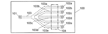
- FIG. 1 An example of a microfluidic device used in the inspection will be described (see FIG. 1).
- On the upper surface of the microfluidic device 100 one inlet 101 and five air ports 102a to 102e are provided.
- a bacteria solution introduction channel 103 having one end directly below the introduction port 101 is provided.
- the bacterial solution introduction channel 103 is branched into five branch channels 103a to 103e on the way, and these branch channels extend to just below the air ports 102a to 102e, respectively.
- the five branch channels 103a to 103e are arranged in parallel with each other near the air ports 102a to 102e.
- antibacterial liquids a to d containing the same kind of antibacterial agents at different concentrations are introduced from the air ports 102a to 102d into the branch channels 103a to 103d.
- the amount of the antibacterial liquids a to d introduced here is such an amount as to stay inside the branch flow paths 103a to 103d (not reach the bacterial liquid introduction flow path 103).
- No antibacterial liquid is introduced into the branch channel 103e.
- the antibacterial liquids ad introduced into the branch channels 103a to 103d are dried to fix the antibacterial agent on the wall surfaces of the branch channels 103a to 103d.
- a bacterial solution containing the target bacterium is introduced into the bacterial solution introduction channel 103 from the inlet 101. Since the air ports 102a to 102e for ventilation are formed at the ends of the branch channels 103a to 103e, the air in the branch channels 103a to 103e is discharged from the air ports with the inflow of the bacterial solution. Bacterial liquid flows into each of the branch channels 103a to 103e. In the branch passages 103a to 103d, the inflowing bacterial liquid comes into contact with the antibacterial agent fixed on the wall surface of each passage.
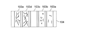
- the microfluidic device 100 is set at a predetermined position of the microscope, and an image of an area (observation area) 104 captured in the field of view of the microscope is acquired. Then, a portion corresponding to each of the branch channels 103a to 103e is specified from the image of the observation region 104, and the state of the target bacterium existing in the branch channels 103a to 103e is confirmed.
- the antibacterial liquid is not introduced into one of the branch channels (the branch channel 103e in the above example), the number and shape of the bacteria confirmed from the image of the branch channel 103e By comparing the number and shape of the bacteria confirmed from the images of the other branch channels 103a to 103d, it is possible to know at what concentration the antibacterial liquid containing the antibacterial agent will exert an effect on the target bacteria.
- the test is performed using a large number of microfluidic devices. For each of such a large number of microfluidic devices, the microfluidic device is imaged and the number of target bacteria present in the flow path is counted. Work such as checking the shape of the target bacterium had to be performed, which was a heavy burden on the inspector.
- the problem to be solved by the present invention is to provide a microfluidic device observation device and a microfluidic device observation method which can easily grasp the state of a test object present inside a flow channel provided in a microfluidic device. To provide.
- a first aspect of the present invention made to solve the above-described problem is a microfluidic device observation apparatus for observing a test object present in a plurality of flow paths provided in a microfluidic device.
- An imaging unit for acquiring an image of the microfluidic device
- An extraction pixel selection unit that selects an extraction pixel from the plurality of pixels based on a predetermined criterion based on the luminance values of the plurality of pixels constituting the obtained image
- a flow path identification unit that identifies the positions of the plurality of flow paths included in the image
- An object feature pixel group detection unit that detects a continuous predetermined number or more of the extracted pixels as an object feature pixel group, which is present inside the specified plurality of flow paths
- a statistical feature amount calculating unit for obtaining a statistical feature amount of the test object feature pixel group based on the number and / or shape of the test object feature pixel group.
- the type of the imaging unit is not limited as long as it can acquire an image in which a contrast appears at the boundary of the flow path formed in the microfluidic device or at the position where the test object exists.
- the imaging unit for example, an optical microscope, an optical camera, a phase contrast microscope, and a differential interference microscope can be used.
- the microfluidic device observation apparatus first, the microfluidic device is set at a predetermined position of the imaging unit so that the region where the plurality of flow paths are provided can be captured in the field of view, An image of the area is obtained.
- the extraction pixel selection unit selects an extraction pixel from the plurality of pixels based on a predetermined criterion based on the luminance values of the plurality of pixels constituting the acquired image.
- the threshold value is a luminance value (background luminance value) assumed for a pixel at a position where neither the boundary of the flow path nor the test object exists, and a pixel whose luminance is higher (or lower) than the threshold value Is specified.
- the threshold value is the average value of the luminance of all the pixels, or the luminance value of the pixel at a position where neither the boundary of the flow path nor the test object is considered to exist, such as the four corners of the image, and the luminance is lower than the threshold.
- High (or low) pixels may be specified.
- an edge intensity (a luminance change amount) is obtained from image data using a differential filter, and an extracted pixel is selected based on a result of comparing the value with a predetermined value. You may do so.
- a differential filter it is possible to remove a background and to easily select an extraction pixel corresponding to a boundary of a flow path or a test object in the flow path. Note that whether to select a pixel with high luminance or a pixel with low luminance is determined according to the characteristics of the imaging unit to be used (whether the boundary of the flow path or the test object appears as light or dark). I just need.
- the flow path specifying unit specifies the positions of the plurality of flow paths included in the image of the microfluidic device acquired by the imaging unit. This can be performed, for example, by preparing a template image of the microfluidic device to be used, and matching the template image with the image obtained by the imaging unit.
- the position of the flow path may be specified by comparing the image of the microfluidic device itself with the template image, or the position of the extraction pixel selected by the extraction pixel selection unit may be compared with the template image. May be used to specify the position of the flow path.
- the microfluidic device has a plurality of flow paths having the same width in at least a part of the area, the plurality of flow paths are arranged in parallel. Can be specified.
- the extracted pixels selected by the extracted pixel selection unit may include pixels corresponding to the positions where they exist. Therefore, next, a predetermined number or more of continuous extracted pixels existing inside the specified plurality of flow paths are detected as a test object characteristic pixel group.
- the predetermined number may be the number of pixels corresponding to the minimum size assumed as the test object. Since noise data rarely exists continuously in a large number of pixels, this processing removes noise.
- the statistical feature value calculating unit calculates the statistical feature value of the test object feature pixel group based on the number and / or shape of the test subject feature pixel group.
- the statistical feature amount is an amount (value) related to the number and shape of the test object feature pixel group.
- the statistical feature amount may include one that does not directly depend on the shape of the test object feature pixel group, such as the area and length of the test object feature pixel group.
- the number of test object characteristic pixel groups corresponds to the number of test objects present in the flow path.
- the shape of the test object characteristic pixel group that is, the array of pixels constituting each test object characteristic pixel group, corresponds to the shape of one test object.
- images acquired by the imaging unit are sequentially processed by the flow path identification unit, the extracted pixel selection unit, the test object characteristic pixel group detection unit, and the statistical characteristic amount calculation unit.
- the statistical feature amount of the test object existing in the flow path is obtained. Therefore, it is not necessary for the inspector to count the number of the test objects present in the flow path and check the shape thereof, and the state of the test objects can be easily grasped.
- the statistical feature amount calculation unit obtains a representative value of the statistical feature amount of the plurality of test object feature pixel groups when a plurality of the test object feature pixel groups exist in one flow path. It can be configured as follows.
- the representative value of the statistical feature can be appropriately selected from a group consisting of an average value, a median value, a mode value, and a combination thereof.
- the microfluidic device observation device further includes: A determination unit that determines the state of the test object based on a result of comparing the statistical characteristic amount obtained for one of the plurality of flow paths with the statistical characteristic amount obtained for another flow path. It is possible to adopt a configuration provided.
- the drug When testing the sensitivity of a test substance such as a cell or a bacterium to a drug such as an antibacterial drug, generally, the drug is not introduced into one of a plurality of flow paths, and the test substance existing inside the flow path is not introduced.
- the number and shape of the objects are used as criteria for determining the state of the object.
- the state can be easily known by using the microfluidic device observation apparatus of this aspect.
- the state of the test object may be determined based on a representative value of the statistical characteristic amounts.
- a second aspect of the present invention made to solve the above-mentioned problem is a microfluidic device observation apparatus for observing a test object present in a plurality of flow paths provided in a microfluidic device.
- An imaging unit for acquiring an image of the microfluidic device
- a flow path identification unit that identifies the positions of the plurality of flow paths included in the image
- an identification unit that specifies the number and / or shape of the test object present inside the specified plurality of flow paths, It is characterized by having.
- a microfluidic device observation apparatus In the microfluidic device observation apparatus according to the second aspect, a microfluidic device acquired by an imaging unit instead of the extracted pixel selection unit, the specimen characteristic pixel group detection unit, and the statistical characteristic amount calculation unit in the first aspect. Is input, an identification unit that specifies the number and / or shape of the test object included in each of the plurality of flow paths specified by the flow path specifying unit is used. By using the microfluidic device observation apparatus of this aspect, the state of the test object can be easily grasped as in the first aspect.
- the microfluidic device observation device When the test object is a biological sample such as a cell or a bacterium, the microfluidic device observation device according to the second aspect, wherein the identification unit further includes: It can be configured to determine the state of the test object present inside the flow path.
- test object is a biological sample
- the state can be easily known by using the microfluidic device observation apparatus of this embodiment.
- microfluidic device observation technology can be suitably used for testing the sensitivity of a target bacterium to a drug.
- a third aspect of the present invention made to solve the above-described problem is a microfluidic device for observing bacteria introduced together with a drug inside a plurality of flow paths provided in a microfluidic device.
- a device observation method Obtaining an image of the microfluidic device, Select an extracted pixel from the plurality of pixels based on a predetermined reference based on the luminance values of the plurality of pixels constituting the obtained image, Identifying the positions of the plurality of channels included in the image, Present inside the specified plurality of flow paths, detecting a continuous predetermined number or more of the extracted pixels as a test object characteristic pixel group, The statistical feature amount of the test object feature pixel group is obtained based on the number and / or shape of the test object feature pixel group.
- a microfluidic device for observing bacteria introduced together with a drug inside a plurality of flow channels provided in a microfluidic device.
- a device observation method Obtaining an image of the microfluidic device, Identifying the positions of the plurality of channels included in the image, Identifying the number and / or shape of the bacteria present in the plurality of identified flow paths in response to the input of the acquired image.
- microfluidic device observation apparatus according to the first or second aspect of the present invention, or the microfluidic device observation method according to the third or fourth aspect, is provided in the microfluidic device.
- the state of the test object existing inside the flow path can be easily grasped.
- FIG. 2 is a configuration diagram of a main part of the microfluidic device observation apparatus according to the first embodiment.
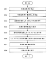
- 5 is a flowchart illustrating a procedure for observing a test object present inside a flow channel of the microfluidic device in the first embodiment.
- 9 is an example of an image obtained by binarizing a luminance value of observation image data in the first embodiment.
- FIG. 4 is a diagram illustrating a template image used in the first embodiment.
- 5 is a flowchart illustrating one of procedures for specifying a flow path position in an observation image in the first embodiment.
- FIG. 4 is a diagram illustrating a method for determining a linear separation distance in one of procedures for specifying a flow path position in an observation image according to the first embodiment.
- 9 is an example of a histogram created in one of the procedures for specifying a flow path position in an observation image in the first embodiment.
- FIG. 6 is a diagram illustrating a method of specifying a flow path from an observation image in one of the procedures for specifying a flow path position in an observation image according to the first embodiment.
- FIG. 9 is a configuration diagram of a main part of a microfluidic device observation apparatus according to a second embodiment.
- Embodiments 1 and 2 of the microfluidic device observation apparatus will be described below with reference to the drawings.
- the microfluidic device 100 described with reference to FIG. 1 is used to test the susceptibility of a target bacterium to antibacterial liquids a to d containing the same antibacterial agent at four different concentrations.
- antibacterial liquids a to d having four concentrations are used, but the number of antibacterial liquids (concentration types) can be changed as appropriate.
- a microfluidic device having six or more flow paths may be used.
- FIG. 2 is a main part configuration diagram of the microfluidic device observation apparatus 1 of the first embodiment.
- the microfluidic device observation apparatus 1 of the present embodiment is roughly divided into a dispensing section 2, an incubator 3, a phase contrast microscope 4 (imaging section), and a control / processing section 10.
- a mechanism (not shown) is provided.
- the control and processing unit 10 has a function of controlling operations of the dispensing unit 2, the incubator 3, and the phase contrast microscope 4, and a function of processing an image obtained by the phase contrast microscope 4.
- the control / processing unit 10 includes a storage unit 11, and further includes, as functional blocks, an extracted pixel selection unit 21, a flow path identification unit 22, an object identification unit 23, a characteristic pixel group detection unit 24, and a flow path boundary pixel group selection unit. 25, a statistical feature amount calculation unit 26, and a determination unit 27.
- the entity of the control / processing unit 10 is a general computer, and these functional blocks are embodied by executing the microfluidic device observation program 20 by the processor.
- the control / processing unit 10 is connected to an input unit 41 for the examiner to input information as appropriate, and a display unit 42 for displaying an image of the flow path of the microfluidic device 100 and the like.
- the storage unit 11 stores a template image of the microfluidic device 100.
- the template image of the microfluidic device 100 is used to identify the position of the flow channel from an image obtained by imaging the microfluidic device 100 with the phase contrast microscope 4. In this embodiment, only one type of microfluidic device 100 is used. However, when a plurality of types of microfluidic devices are used, a template image is prepared for each type and stored in the storage unit 11.
- One introduction port 101 and five air ports 102a to 102e are provided on the upper surface of the microfluidic device 100. Inside the microfluidic device 100, a bacteria solution introduction channel 103 having one end directly below the introduction port 101 is provided.
- the bacterial solution introduction flow path 103 is branched into five branch flow paths 103a to 103e on the way, and these branch flow paths extend linearly to just below the air ports 102a to 102e, respectively.
- the five branch channels 103a to 103e are arranged in parallel with each other near the air ports 102a to 102e.
- FIG. 1 shows the branch channels 103a to 103e in an easy-to-understand manner. In an actual microfluidic device, the channel width of the branch channels 103a to 103e is wider than the channel interval.
- the examiner prepares a bacterial solution containing the target bacterium at a predetermined ratio (for example, defined by the number of the target bacterium and the amount of the culture solution) and antibacterial solutions a to d containing the antibacterial agents used for the test at different concentrations. Is set in the dispensing section 2.
- the control / processing unit 10 transmits a control signal instructing the dispensing unit 2 to start the dispensing operation. If there are a plurality of types of microfluidic devices that can be used, the inspector can specify the type of the microfluidic device 100 to be used for the inspection.
- antimicrobial liquids a to d are introduced into the branch flow paths 103 a to 103 d of the microfluidic device 100, and a bacterial liquid containing the target bacterium is introduced into the bacterial liquid introduction flow path 103 from the inlet 101.
- the antimicrobial solution is not introduced into the branch channel 103e, and the number and size of the target bacteria in the branch channel 103e are determined by determining the sensitivity of the target bacteria to the antimicrobial solutions ad introduced into the other channels. It is used as a reference for judgment.
- the introduction amount of the bacterial solution is determined in advance so as to reach the position of the antibacterial agent fixed in the branch channels 103a to 103d.
- the air in the branch channels 103a to 103e is discharged from the air ports with the inflow of the bacterial solution.
- Bacterial liquid flows into each of the branch channels 103a to 103e.
- the inflowing bacterial liquid comes into contact with the antibacterial agent fixed on the wall surface of each passage.
- the microfluidic device 100 After introducing the antibacterial liquids a to d and the bacterial liquid, the microfluidic device 100 is transported to the incubator 3 and heated to a predetermined temperature for a predetermined time to culture the target bacteria. After culturing for a predetermined time, the microfluidic device 100 is transported from the incubator 3 to the phase contrast microscope 4.
- a procedure for observing a target bacterium existing inside the flow path of the microfluidic device in the microfluidic device observation apparatus 1 of the present embodiment will be described with reference to the flowchart of FIG.
- the microfluidic device 100 transported to the phase contrast microscope 4 is held at a predetermined imaging position in a predetermined direction.
- the phase contrast microscope 4 images a region of the microfluidic device 100 captured in the field of view.
- a region captured in the field of view of the phase contrast microscope 4 (corresponding to at least a part of the microfluidic device 100) is an observation region 104, and the phase contrast microscope 4 has an image of the observation region 104. (Hereinafter, this is referred to as an “observed image.”) (Step S1).
- the phase contrast microscope 4 transmits the acquired image data of the observation region 104 to the control / processing unit 10.
- the received imaging data is stored in the storage unit 11.
- the extracted image selection unit 21 calculates the edge strength (the amount of change in luminance) in the image using the differential filter (Step S2).
- the processing described below may be performed using the image obtained by the phase contrast microscope 4 as it is, by performing the preprocessing using the differential filter, the processing described below can be performed with higher accuracy using the edge intensity in the image. Can proceed.
- a primary differential filter such as a sobel filter, a prewitt filter, a canny filter, or a secondary differential filter such as a laplacian filter can be used.
- various methods for detecting a change in luminance included in image data such as a morphology operation, can be used.
- the extracted image selecting unit 21 selects, as the extracted pixel, a pixel whose edge intensity value is equal to or greater than a predetermined value, from the image data from which the edge intensity has been extracted using the differential filter (Step S3).
- Image data is binarized by assigning a value of 0 to unselected pixels (step S4; see FIG. 4).
- binarization is performed using values of 0 and 1, but binarization may be performed using another value, a sign, or the like.
- the extracted pixel is selected using the same predetermined value regardless of the position in the pixel, but a predetermined value corresponding to the magnitude of the luminance value of each pixel is used (for example, the luminance of the target pixel is selected).
- a pixel having a value of the edge strength equal to or more than a predetermined ratio with respect to the value may be set as the extracted pixel. This makes it possible to appropriately select an extracted pixel even when a bright (high luminance value) portion and a dark (low luminance value) portion exist in the image depending on the environment at the time of imaging.
- different threshold values may be used according to the variance of the luminance value in a predetermined range (for example, a range of 9 pixels ⁇ 9 pixels) around the target pixel in the entire image.
- ⁇ There are roughly two types of processing methods after binarizing image data.
- the channel identifying unit 22 performs template matching by using the template matching. The position of the channel included in the observation image is specified. First, this process will be described.
- the channel identifying unit 22 reads the template image 110 of the microfluidic device 100 from the storage unit 11.
- the template image 110 is an image in which a portion other than the flow path is hatched.
- the channel identifying unit 22 superimposes the template image 110 on the observation image acquired by the phase contrast microscope 4 and shifts the relative positions of the two images little by little, while comparing the boundary of the channel included in the observation image and the template image.
- the position where the degree of coincidence of the boundary of the flow path 110 is the highest is specified.
- the flow path specifying unit 22 sets the template image Is created on the observation image, and an image of each of the branch channels 103a to 103e is specified (step S5). Then, the image data of each of the branch channels 103a to 103e is stored in the storage unit 11, and the images are displayed on the display unit.
- a known template information for example, five linear flow paths are formed on the flow path of the microfluidic device 110 is used, and a linear template filter is used. Images of the respective branch channels 103a to 103e can be extracted based on the degree of coincidence of the images.
- the observation image can be set in advance without using a template image or a template filter. A region existing at a determined position can be automatically extracted as an image of each of the branch channels 103a to 103e. Another method for specifying the flow path will be described later.
- the test object specifying unit 23 When the positions of the branch channels 103a to 103e in the observation image are specified in step S5, the test object specifying unit 23 operates the characteristic pixel group detection unit 24 to exist inside the branch channels 103a to 103e. Identify the target bacteria.
- the test object characteristic pixel group is detected by cooperation of the test object specifying unit 23 and the characteristic pixel group detection unit 24 (that is, it functions as the test object characteristic pixel group detection unit in the present invention). ).
- the characteristic pixel group detection unit 24 sets a predetermined number or more of consecutive extracted pixels from the binarized images of the branch channels 103a to 103e as the test object characteristic pixel group. It is detected (step S6).
- the predetermined number may be any number as long as the target bacterium and noise existing inside the flow path can be separated, for example, the number of pixels (for example, 5 pixels) corresponding to the minimum size assumed as the target bacterium. Can be. Since the noise data rarely exists continuously in a large number of pixels, this process can remove noise included in the binarized image of the flow path.
- the statistical characteristic amount calculation unit 26 determines the number of the characteristic pixel groups of the test object (the target bacteria) existing in each of the branch channels 103a to 103e. ) And the arrangement of pixels (shape of the target bacterium) constituting each of the test object characteristic pixel groups. As a result, statistical features relating to the number and shape of the test objects existing inside each of the branch channels 103a to 103e are obtained (step S7).
- the sum of the statistical characteristic amounts of the specimen characteristic pixel groups corresponding to the plurality of target bacteria is divided by the number. A statistical feature representing an average shape of the test object is obtained.
- the statistical features related to the shape of the target bacterium include the area (or area ratio) of the target bacterium, the perimeter of the target bacterium, the long axis length and the short axis length of the target bacterium, and the linearity and circularity of the target bacterium.
- the area ratio of the target bacterium can be determined from the ratio of the number of pixels constituting the test object characteristic pixel group to the number of pixels in the flow channel.
- the perimeter of the target bacterium can be obtained from the perimeter of the target feature pixel group.
- the long axis length and the short axis length of the target bacterium can be obtained as the maximum value and the minimum value of the linear length of the rectangle surrounding the test object characteristic pixel group.
- the linearity and circularity of the target bacterium can be obtained from the aspect ratio of the shape of the test object characteristic pixel group or a predetermined mathematical formula (for example, 4 ⁇ ⁇ area ⁇ (perimeter) 2 ).
- Other well-known statistics can be appropriately used as the statistical feature.
- the average of the statistical features is obtained, but a median, a mode, or the like may be obtained in addition to the average.
- the determination unit 27 determines the statistical feature amount of the target bacterium in the branch channel 103e into which the antibacterial liquid has not been introduced. Based on the statistical characteristics of the target bacteria in the branch channels 103a to 103d into which different concentrations of the antibacterial liquids a to d are respectively introduced, the state of the target bacteria existing in the channels (including the antimicrobial agent at different concentrations) (Sensitivity to antimicrobial liquids a to d) is determined (step S8). The image of the flow path, the statistical feature obtained from the image, and the determination result based on the statistical feature are displayed on the display unit 42.
- information on the change in the form of the target bacterium may be output.
- the shape (linearity, circularity, etc.) of the target bacterium inside the branch channels 103a to 103d is different from the shape of the target bacterium in the branch channel 103e
- the change of the statistical feature amount corresponding to the shape is determined. It can be configured to be displayed on the display unit 42. This makes it possible to obtain information on whether or not the target bacterium is denatured due to the action of the antibacterial agent.
- the flow channel identification unit 22 includes the characteristic pixel group detection unit 24 and the flow channel boundary pixel.
- the group selection unit 25 is sequentially operated to extract the image of the channel.
- the flow path characteristic pixel group is detected by the cooperation of the flow path identification unit 22 and the characteristic pixel group detection unit 24.
- the extracted pixels selected by the extracted image selection unit 21 include a pixel located at the boundary of the flow path, a pixel at a position where the target bacterium exists, a pixel at a position where noise has occurred, and the like. Therefore, the characteristic pixel group detection unit 24 detects a predetermined number or more of extracted pixels that are arranged linearly continuously from the binarized image data as a flow path characteristic pixel group (step S5-1).
- the predetermined number is a number that allows the shape of the channel characteristic pixel group to be estimated from the positions of the pixels. What should be the predetermined number depends on the shape of the flow path.
- a straight line expression representing the flow path characteristic pixel group is obtained based on the positions (coordinates) of the pixels constituting the flow path characteristic pixel group. If the number is too small, the accuracy of the linear expression is poor. On the other hand, as the predetermined number increases, a straight line expression representing the flow path characteristic pixel group can be obtained with higher accuracy.However, when the predetermined number is too large, contrast does not appear in some of the pixels located at the boundary of the flow path. If the extracted pixels are not selected (that is, if the number of consecutive extracted pixels is small), the extracted pixels located at the boundary of the flow channel will not be detected as the flow channel characteristic pixel group. In consideration of these, it is preferable that the predetermined number is about the number of pixels corresponding to a length corresponding to 10% of an image size (a short diameter for a rectangular image, a diameter for a circular image).
- the channel boundary pixel group selection unit 25 assigns a number m (m is an integer of 1 to n) to the n channel characteristic pixel groups detected by the characteristic pixel group detection unit 24, and obtaining a linear equation L m representing the road feature pixel group (step S5-2).
- the linear equation L m representing the channel characteristic pixel groups means an approximate straight line based on the coordinates of a plurality of extraction of pixels constituting the flow path, wherein the pixel group.
- a Hough transform in order to obtain the linear equation L m represent each flow path, wherein the pixel group.
- Hough transform is one of the techniques used when extracting image features in the field of image processing.
- a linear expression is expressed on a two-dimensional plane (xy plane) by a distance r of a normal from the origin to a straight line and an angle ⁇ formed by the normal and the x-axis.
- Equation (1) a straight line equation using Equation (1) is obtained for one of the extracted pixels constituting the channel characteristic pixel group.
- the linear equation is not uniquely determined, and is a function of r and ⁇ .
- a function of r and ⁇ is obtained using the coordinates of the extracted pixels.
- functions of r and ⁇ obtained by the number of extracted pixels are projected onto a Hough space having these as two axes, and values of r and ⁇ having the largest number of projections (highest degree of coincidence) are obtained.
- a straight line expression representing the channel characteristic pixel group is determined.
- the channel characteristic pixel group When the extracted pixels constituting the channel characteristic pixel group are located on a straight line, the functions of r and ⁇ obtained for each of the extracted pixels intersect at one point, and the values of r and ⁇ at the intersection point Strictly determines the straight line.
- the channel characteristic pixel group extends over a plurality of pixels in the width direction or is partially stepped, so that the extracted pixels may not be perfectly aligned. Few. Therefore, a straight line equation corresponding to the channel feature pixel group is determined based on the values of r and ⁇ having a large number of projections in the Hough space.
- Flow path boundary pixel group selecting section 25 then performs inclination judgment of linear equation L m obtained for each of the channel characteristic pixel group.
- Unit vector v m representing the gradient of the linear equation L m represented by the above formula (2) is expressed by the following equation (3).
- the channel characteristic pixel group (outlier) corresponding to the straight line having a slope that does not satisfy the following equation (4) is excluded from the processing target (step S5-3).
- Equation (4) has a slope v m of linear equation L m corresponding to the flow path, wherein the pixel group, which is the inner product of all those median v ctr. ⁇ is a real number greater than or equal to 0 and less than 1. That is, Expression (4) means that the parallelism with respect to the straight line having the gradient of the average value v ctr is equal to or greater than a certain value (the gradient v m of the linear expression L m is close to the gradient of another linear expression).
- the plurality of branch channels 103a to 103e are formed in parallel in the observation region 104, a straight line corresponding to the channel characteristic pixel group located at the boundary of each channel.
- the flow path characteristic pixel group (such as a target bacterium, etc.) that is not considered to be a boundary of the flow path. Corresponding to the position) can be excluded.
- a median v ctr of linear equation L m corresponding to each channel wherein pixel groups need not always median, the slope v of the linear equation L m corresponding to the flow path, wherein the pixel group m average or obtains a distribution of inclination v m of linear equation L m corresponding to the flow path, wherein the pixel group, such as average, excluding the predetermined number of inclination corresponding to the ends of the distribution, is possible to use a suitable it can. Further, when it is possible to estimate the approximate inclination of the straight line corresponding to the boundary of the flow path (the inclination of the flow path in the observation image), the estimated value can be used.
- the k (k ⁇ n) linear formulas L p (p is an integer of 1 or more and k or less) remaining after the above processing are adjacent to each other in a specific direction (eg, the positive direction of the x-axis) when viewed from each straight line.
- the distance from another straight line is determined (step S5-4).
- the normal L of the straight line formula L p passing through the center C of the observed image the intersection of the 'demanded may be the distance between the intersections with the distance d p between both straight lines.
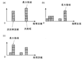
- a histogram is created with a predetermined class width for the distance d p between the straight lines obtained for each of the k-1 straight lines (step S5-5).
- the channel widths and channel intervals of the branch channels 103a to 103e formed in the microfluidic device 100 of this embodiment are all constant. Accordingly, the histogram is created, the distance d p corresponding to the channel width is most, then it should be many distance d p corresponding to the channel spacing. Therefore, for each of the k-1 straight line, it is determined whether the distance d p about the straight line is included in the maximum class.
- five branch channels 103a to 103e are formed in parallel. Therefore, ideally, as shown in FIG. 8A, four data exist at positions corresponding to the distance between the flow paths, and five data exist at positions corresponding to the flow path width, and at other positions, Has no data. If such a histogram is obtained, it is determined that the separation distance d p obtained for the five straight lines is included in the maximum class. By extracting a set of a straight line L p corresponding to the one determined to be included in the maximum class and a straight line L p + 1 adjacent to the straight line, a pixel group ( Flow path boundary pixel group) can be selected.
- a straight line (a straight line derived from the target bacterium or a straight line derived from noise) other than the straight line constituting the boundary of the flow path is included.
- a histogram as shown in FIGS. 8B and 8C is obtained.
- the straight lines forming the boundaries of the flow paths are located at fixed intervals according to the flow path width and the distance between the flow paths, while the other straight lines are randomly located. Therefore, when the maximum class in the histogram is selected, either the channel width (FIG. 8B) or the distance between the channels (FIG. 8C) is selected.
- a pixel group constituting a flow path boundary (flow path boundary pixel group) is extracted. Can be selected (step S5-7).
- the position of the boundary of the channel in the observation image can be known as shown in FIG. 9A or 9B.
- FIG. 9A the state obtained from the histogram of FIG. 8A or FIG. 8B
- a region sandwiched between two sets of straight lines from the end of the image (hatching) May be used as a flow path.
- FIG. 9B the state obtained from the histogram of FIG. 8C
- FIG. 9B the state obtained from the histogram of FIG. 8C
- two lines are selected as one set from the end, and the flow path width in the case where the region sandwiched between them is the flow path, and the width from the end Two lines are selected as one set in order from the second straight line, and a comparison is made as to which one of the flow path widths when the area sandwiched between them is a flow path.
- the channel width is shown narrow for easy understanding of the channel, but in a microfluidic device actually used, the channel width is wider than the channel interval. Therefore, the one determined to be wider as a result of the comparison is defined as the flow path.
- the linearly located channel boundary pixel group is located at both ends of the image. One by one remains. It is determined whether a flow path having the same width as another flow path can be added outside each of the straight lines left at both ends (that is, whether a space corresponding to the flow path width remains outside the straight line). If possible, a straight line corresponding to the boundary of the flow path (indicated by a dashed line in FIG. 9C) is added. Thereby, a flow path is added.
- the flow path identification unit 22 specifies the position of each of the flow paths 103a to 103e included in the observation image (Step S5, Step S5-8). Then, the image data of each of the flow paths 103a to 103e is stored in the storage unit 11, and the images are displayed on the display unit 42. At this time, the image of the position of the specified flow path may be extracted as it is, but in order to prevent the contrast of the boundary of the flow path from affecting the image of the flow path and preventing the contrast from being mistaken as the target bacterium. Alternatively, a region inside a predetermined number of pixels from the determined position of the flow path may be extracted as a flow path image.
- FIG. 10 is a main part configuration diagram of the microfluidic device observation apparatus 1a of the embodiment.
- the same components as those of the microfluidic device observation apparatus 1 of the first embodiment are denoted by the same reference numerals, and description thereof is omitted.
- the microfluidic device observation device 1a according to the second embodiment differs from the microfluidic device observation device 1 according to the first embodiment in part of the configuration of the control / processing unit.
- the control / processing unit 10 a has a function of controlling the operations of the dispensing unit 2, the incubator 3, and the phase-contrast microscope 4, and an image obtained by the phase-contrast microscope 4, similarly to the control / processing unit 10 of the first embodiment. Processing function.
- the control / processing unit 10a includes a storage unit 11a, and includes an extracted pixel selection unit 21 and a flow path identification unit 22 as functional blocks. Further, an identification unit 28 constructed by machine learning described later is installed.
- the entity of the control / processing unit 10a is a general computer, and the functional blocks are embodied by executing the microfluidic device observation program 20a by its processor.
- the control / processing unit 10 is connected to an input unit 41 for the examiner to input information as appropriate, and a display unit 42 for displaying an image of the flow path of the microfluidic device 100 and the like.
- the storage unit 11a stores the template image 110 described in the first embodiment and a number of test object reference images.
- the test object reference image is an image obtained by photographing a target bacterium, which is the same test object as in the present embodiment, in which various kinds of antibacterial agents are applied at various concentrations. Each of these images has been analyzed, and the statistical feature amount related to the number and shape of the target bacteria contained in each image is specified in advance.
- the specimen reference image in addition to the image of the target bacterium having a standard shape, an image of the shape changed by modification with an antibacterial agent is also included, and the statistical feature amount of the image is also included. It has been demanded.
- the microfluidic device observation apparatus 1a is characterized in a process of calculating a statistical feature amount of a target bacterium existing inside a flow path and determining a state of the target bacterium.
- the identification unit 28 is created by machine learning using a large number of test object reference images stored in the storage unit 11 as learning data.
- a machine learning method for example, a method such as deep learning, a support vector machine (SVM: ⁇ Support ⁇ Vector ⁇ Machine), or a random forest has been proposed.
- the machine learning using the image of the channel of the microfluidic device 100 and the statistical feature amount of the target bacterium corresponding to the image as learning data.
- an identification unit 28 for specifying the number and shape of the target bacteria from the input image is constructed.
- the microfluidic device 100 is imaged by the phase contrast microscope 4, the image data is processed by the differential filter to obtain the edge strength, and the process of binarizing the image data is performed in the first embodiment.
- the microfluidic device observation apparatus 1 any one of the methods described in the first embodiment is used for the process of specifying the position of the channel in the observation image.
- the image data of the branch channels 103a to 103d is input to the identification unit 28.
- the identification unit 28 specifies the number and shape (for example, linearity and circularity) of the test objects included in each of the input images of the branch channels 103a to 103e, and uses them to determine the statistical characteristics of the target bacteria. Output as quantity.
- an average of the respective statistical feature amounts for the plurality of target bacteria is output.
- the identification unit 28 may be constructed by machine learning that outputs the corresponding statistical features in response to the input of the image of the flow path containing the target bacteria.
- the average of the statistical feature amounts is obtained, but a median value, a mode value, and the like may be obtained in addition to the average value.
- the identification unit 28 determines the average of the statistical features of the target bacteria in the branch channel 103e into which the antimicrobial solution has not been introduced, as in the first embodiment.
- the states (sensitivities to antimicrobial liquids a to d containing antimicrobial agents at different concentrations) are determined from the statistical characteristics of the target bacteria in the branch channels 103a to 103d into which antimicrobial liquids a to d having different concentrations are introduced, respectively. I do.
- the image of the flow path, the statistical feature obtained from the image, and the determination result based on the statistical feature are displayed on the display unit 42.
- the method of detecting the boundary of the flow path and extracting the characteristic pixels of the bacteria by the same method has been described.
- the methods may be performed by different methods.
- the shape including information such as area
- the shape can be detected by extracting the characteristic pixels of the bacterium by, for example, machine learning.
- the number of channels is determined by the number of antibacterial liquids (concentration of concentration) used for inspection. (Type) can be appropriately changed.
- the shape of the flow path is not limited to a straight line, but may be a curved line.
- the curved shape may be, for example, an arc shape (including an elliptical arc) or an S shape (meandering shape). The Hough transform described in this specification can be applied even if the flow path has a curved shape.
- the shape of the characteristic pixel group is obtained by a mathematical expression representing a circle or an ellipse instead of the Hough transform of the above embodiment, and the shape of the characteristic pixel group is replaced by the parallelism of the straight line in the embodiment.
- the parallelism of a curve For example, for a certain curve, the concept of a parallel curve defined as a curve at a certain distance in the normal direction from each point on the curve can be used.
- the phase contrast microscope is used as the imaging unit.
- the imaging unit can obtain an image in which contrast appears at the boundary of the flow path formed in the microfluidic device.
- the type is not limited.
- an optical microscope, an optical camera, and a differential interference microscope can be used.
- the flow path is determined without performing the above comparison, the flow path identification unit 22 extracts an image of the flow path, and the extracted image is displayed on the display unit 42. If it is determined that the reverse operation (the area sandwiched by two straight lines different from the set of straight lines used as the boundaries constituting the flow path earlier) is used as the flow path, and the flow path identifying unit 22 extracts the image. Operation).
- the observation image in which the position of the flow path is specified is input to the identification unit 28.
- image data of the microfluidic device 100 image data in which the position of the flow path is not specified. May be directly input to the identification unit 28, and the identification unit 28 may be used to specify the position of the flow path.
- the identification unit 28 is obtained by machine learning in which image data of microfluidic devices in which various numbers and shapes of channels are formed, and in which the position of each channel is already specified as learning data. May be configured.
- Microfluidic device observation apparatus 2 Dispensing unit 3: Incubator 4: Phase contrast microscope 10a: Control / processing unit 10, 10a: Control / processing unit 11, 11a: Storage unit 110: Template images 20, 20a ... Microfluidic device observation program 21 Extracted pixel selecting unit 22 Flow path specifying unit 23 Test object specifying unit 24 Characteristic pixel group detecting unit 25 Flow path boundary pixel group selecting unit 26 Statistical characteristic amount calculating unit 27 Judgment unit 28 Identification unit 41 Input unit 42 Display unit 100 Microfluidic device 101 Inlets 102a to 102e Air ports 103 Bacterial solution introduction channels 103a to 103e Branch channels 104 Observation area 110 Template image
Landscapes
- Chemical & Material Sciences (AREA)
- Engineering & Computer Science (AREA)
- Health & Medical Sciences (AREA)
- Physics & Mathematics (AREA)
- Life Sciences & Earth Sciences (AREA)
- General Physics & Mathematics (AREA)
- Analytical Chemistry (AREA)
- General Health & Medical Sciences (AREA)
- Biochemistry (AREA)
- Dispersion Chemistry (AREA)
- Organic Chemistry (AREA)
- Bioinformatics & Cheminformatics (AREA)
- Immunology (AREA)
- Wood Science & Technology (AREA)
- Zoology (AREA)
- Pathology (AREA)
- Theoretical Computer Science (AREA)
- Biotechnology (AREA)
- Multimedia (AREA)
- Computer Vision & Pattern Recognition (AREA)
- Microbiology (AREA)
- General Engineering & Computer Science (AREA)
- Genetics & Genomics (AREA)
- Software Systems (AREA)
- Clinical Laboratory Science (AREA)
- Optics & Photonics (AREA)
- Sustainable Development (AREA)
- Biomedical Technology (AREA)
- Signal Processing (AREA)
- Hematology (AREA)
- Chemical Kinetics & Catalysis (AREA)
- Proteomics, Peptides & Aminoacids (AREA)
- Computing Systems (AREA)
- Artificial Intelligence (AREA)
- Databases & Information Systems (AREA)
- Evolutionary Computation (AREA)
- Medical Informatics (AREA)
- Medicinal Chemistry (AREA)
- Fluid Mechanics (AREA)
- Molecular Biology (AREA)
Abstract
Description
前記マイクロ流体デバイスの画像を取得する撮像部と、
取得した前記画像を構成する複数の画素の輝度値に基づいて所定の基準により該複数の画素の中から抽出画素を選択する抽出画素選択部と、
前記画像に含まれる前記複数の流路の位置を特定する流路特定部と、
前記特定した複数の流路の内部に存在する、連続する所定個数以上の前記抽出画素を被検物特徴画素群として検出する被検物特徴画素群検出部と、
前記被検物特徴画素群の数及び/又は形状に基づいて該被検物特徴画素群の統計特徴量を求める統計特徴量算出部と
を備えることを特徴とする。
前記統計特徴量算出部が、1つの流路の内部に複数の前記被検物特徴画素群が存在する場合に、該複数の前記被検物特徴画素群の前記統計特徴量の代表値を求めるように構成することができる。前記統計特徴量の代表値は、平均値、中央値、最頻値、及びこれらの組み合わせからなる群から適宜に選択することができる。この態様のマイクロ流体デバイス観察装置を用いることにより、例えば各流路内に存在する被検物の平均的な大きさや形状を簡便に知ることができる。
前記複数の流路のうちの1つについて求められた前記統計特徴量を他の流路について求められた前記統計特徴量と比較した結果に基づいて前記被検物の状態を判定する判定部
を備えた構成を採ることができる。
前記マイクロ流体デバイスの画像を取得する撮像部と、
前記画像に含まれる前記複数の流路の位置を特定する流路特定部と、
取得された前記画像が入力されると、前記特定された複数の流路の内部に存在する前記被検物の数及び/又は形状を特定する識別部と、
を備えることを特徴とする。
ように構成することができる。
前記マイクロ流体デバイスの画像を取得し、
取得した前記画像を構成する複数の画素の輝度値に基づいて所定の基準により該複数の画素の中から抽出画素を選択し、
前記画像に含まれる前記複数の流路の位置を特定し、
前記特定した複数の流路の内部に存在する、連続する所定個数以上の前記抽出画素を被検物特徴画素群として検出し、
前記被検物特徴画素群の数及び/又は形状に基づいて該被検物特徴画素群の統計特徴量を求める
ことを特徴とする。
前記マイクロ流体デバイスの画像を取得し、
前記画像に含まれる前記複数の流路の位置を特定し、
取得された前記画像の入力に応じて前記特定した複数の流路の内部に存在する前記菌の数及び/又は形状を特定する
を備えることを特徴とする。
r=x cosθ+y sinθ …(1)
amx+bmy=1 (am, bmは係数)…(2)
vm=(-bm/lm, am/lm) (ただし、lm=(am 2+bm 2)1/2) …(3)
|<vm・vctr>|≧α (αは0以上1未満の値) …(4)
2…分注部
3…インキュベータ
4…位相差顕微鏡
10a…制御・処理部
10、10a…制御・処理部
11、11a…記憶部
110…テンプレート画像
20、20a…マイクロ流体デバイス観察用プログラム
21…抽出画素選択部
22…流路特定部
23…被検物特定部
24…特徴画素群検出部
25…流路境界画素群選択部
26…統計特徴量算出部
27…判定部
28…識別部
41…入力部
42…表示部
100…マイクロ流体デバイス
101…導入口
102a~102e…空気口
103…菌液導入流路
103a~103e…分岐流路
104…観察領域
110…テンプレート画像
Claims (14)
- マイクロ流体デバイスに配設された複数の流路の内部に存在する被検物を観察するためのマイクロ流体デバイス観察装置であって、
前記マイクロ流体デバイスの画像を取得する撮像部と、
取得した前記画像を構成する複数の画素の輝度値に基づいて所定の基準により該複数の画素の中から抽出画素を選択する抽出画素選択部と、
前記画像に含まれる前記複数の流路の位置を特定する流路特定部と、
前記特定した複数の流路の内部に存在する、連続する所定個数以上の前記抽出画素を被検物特徴画素群として検出する被検物特徴画素群検出部と、
前記被検物特徴画素群の数及び/又は形状に基づいて該被検物特徴画素群の統計特徴量を求める統計特徴量算出部と
を備えることを特徴とするマイクロ流体デバイス観察装置。 - 前記統計特徴量算出部が、1つの流路の内部に複数の前記被検物特徴画素群が存在する場合に、該複数の前記被検物特徴画素群の前記統計特徴量の代表値を求める
ことを特徴とする請求項1に記載のマイクロ流体デバイス観察装置。 - さらに、
前記複数の流路のうちの1つについて求められた前記統計特徴量を他の流路について求められた前記統計特徴量と比較した結果に基づいて前記被検物の状態を判定する判定部
を備えることを特徴とする請求項1に記載のマイクロ流体デバイス観察装置。 - マイクロ流体デバイスに配設された複数の流路の内部に存在する被検物を観察するためのマイクロ流体デバイス観察装置であって、
前記マイクロ流体デバイスの画像を取得する撮像部と、
前記画像に含まれる前記複数の流路の位置を特定する流路特定部と、
取得された前記画像が入力されると、前記特定された複数の流路の内部に存在する前記被検物の数及び/又は形状を特定する識別部と、
を備えることを特徴とするマイクロ流体デバイス観察装置。 - 前記識別部が、1つの流路の内部に複数の前記被検物が存在する場合に、該複数の前記被検物の数及び/又は形状に関連する統計特徴量の代表値を求める
ことを特徴とする請求項4に記載のマイクロ流体デバイス観察装置。 - 前記識別部が、さらに、
前記特定した前記被検物の数及び/又は形状に基づいて各流路の内部に存在する前記被検物の状態を判定する
ことを特徴とする請求項4に記載のマイクロ流体デバイス観察装置。 - 前記マイクロ流体デバイスの少なくとも一部の領域において前記複数の流路は同一の幅を有して平行に配設されており、
前記流路特定部が、
それぞれが線状に連続に並ぶ所定個数以上の前記抽出画素からなる複数の抽出画素群のうち、相互の平行度が予め決められた平行度以上である複数の抽出画素群をそれぞれ流路特徴画素群として検出する流路特徴画素群検出部と、
前記複数の流路特徴画素群の中から、離間距離が前記流路の幅に対応する特徴画素群の組を流路境界画素群として選択する流路境界画素群選択部と、
前記画像における前記流路境界画素群の位置に基づき前記1乃至複数の流路の境界の位置を特定して各流路の画像を抽出する流路画像抽出部と
を有することを特徴とする請求項1又は4に記載のマイクロ流体デバイス観察装置。 - 前記抽出画素選択部が、微分フィルタを用いて前記画像のエッジ強度を求めることを特徴とする請求項6に記載のマイクロ流体デバイス観察装置。
- 前記流路が直線状に形成されており、
前記流路特徴画素群検出部が、前記抽出画素群のそれぞれについて、当該抽出画素群を構成する画素の位置に対応する近似直線を求め、該近似直線の傾きと他の近似曲線の傾きの差が予め決められた大きさ以下であるものを特徴画素群として検出することを特徴とする請求項6に記載のマイクロ流体デバイス観察装置。 - 前記流路特徴画素群検出部が、ハフ変換により前記近似直線を求めることを特徴とする請求項9に記載のマイクロ流体デバイス観察装置。
- 前記流路が複数、互いに平行に設けられており、
前記流路境界画素群選択部が、隣接する2つの前記流路特徴画素群の離間距離が等しいものを前記流路境界画素群として選択することを特徴とする請求項6に記載のマイクロ流体デバイス観察装置。 - 前記流路境界画素群選択部が、前記離間距離に関するヒストグラムを作成し、その最大階級に属するものを前記流路境界画素群として選択することを特徴とする請求項11に記載のマイクロ流体デバイス観察装置。
- マイクロ流体デバイスに配設された複数の流路の内部に、薬剤とともに導入された菌を観察するためのマイクロ流体デバイス観察方法であって、
前記マイクロ流体デバイスの画像を取得し、
取得した前記画像を構成する複数の画素の輝度値に基づいて所定の基準により該複数の画素の中から抽出画素を選択し、
前記画像に含まれる前記複数の流路の位置を特定し、
前記特定した複数の流路の内部に存在する、連続する所定個数以上の前記抽出画素を被検物特徴画素群として検出し、
前記被検物特徴画素群の数及び/又は形状に基づいて該被検物特徴画素群の統計特徴量を求める
ことを特徴とするマイクロ流体デバイス観察方法。 - マイクロ流体デバイスに配設された複数の流路の内部に、薬剤とともに導入された菌を観察するためのマイクロ流体デバイス観察方法であって、
前記マイクロ流体デバイスの画像を取得し、
前記画像に含まれる前記複数の流路の位置を特定し、
取得された前記画像の入力に応じて前記特定した複数の流路の内部に存在する前記菌の数及び/又は形状を特定する
ことを特徴とするマイクロ流体デバイス観察方法。
Priority Applications (4)
| Application Number | Priority Date | Filing Date | Title |
|---|---|---|---|
| JP2020531848A JP7250795B2 (ja) | 2018-07-23 | 2018-07-23 | マイクロ流体デバイス観察装置及びマイクロ流体デバイス観察方法 |
| CN201880095672.1A CN112424612B (zh) | 2018-07-23 | 2018-07-23 | 微流体器件观察装置及微流体器件观察方法 |
| US17/262,144 US12140743B2 (en) | 2018-07-23 | 2018-07-23 | Microfluidic device observation device and microfluidic device observation method |
| PCT/JP2018/027554 WO2020021604A1 (ja) | 2018-07-23 | 2018-07-23 | マイクロ流体デバイス観察装置及びマイクロ流体デバイス観察方法 |
Applications Claiming Priority (1)
| Application Number | Priority Date | Filing Date | Title |
|---|---|---|---|
| PCT/JP2018/027554 WO2020021604A1 (ja) | 2018-07-23 | 2018-07-23 | マイクロ流体デバイス観察装置及びマイクロ流体デバイス観察方法 |
Publications (1)
| Publication Number | Publication Date |
|---|---|
| WO2020021604A1 true WO2020021604A1 (ja) | 2020-01-30 |
Family
ID=69181424
Family Applications (1)
| Application Number | Title | Priority Date | Filing Date |
|---|---|---|---|
| PCT/JP2018/027554 Ceased WO2020021604A1 (ja) | 2018-07-23 | 2018-07-23 | マイクロ流体デバイス観察装置及びマイクロ流体デバイス観察方法 |
Country Status (4)
| Country | Link |
|---|---|
| US (1) | US12140743B2 (ja) |
| JP (1) | JP7250795B2 (ja) |
| CN (1) | CN112424612B (ja) |
| WO (1) | WO2020021604A1 (ja) |
Cited By (3)
| Publication number | Priority date | Publication date | Assignee | Title |
|---|---|---|---|---|
| JPWO2022107557A1 (ja) * | 2020-11-18 | 2022-05-27 | ||
| JP2022190404A (ja) * | 2021-06-14 | 2022-12-26 | アサヒ飲料株式会社 | 微生物の検出方法 |
| WO2024135236A1 (ja) * | 2022-12-20 | 2024-06-27 | 株式会社ニコン | マイクロ流体デバイス用観察装置 |
Families Citing this family (2)
| Publication number | Priority date | Publication date | Assignee | Title |
|---|---|---|---|---|
| US12352946B1 (en) * | 2022-12-15 | 2025-07-08 | United States Of America As Represented By The Administrator Of Nasa | Fourier ptychographic microscope systems and methods |
| TWI854614B (zh) * | 2023-04-26 | 2024-09-01 | 眾智光電科技股份有限公司 | 微流體電穿孔裝置 |
Citations (7)
| Publication number | Priority date | Publication date | Assignee | Title |
|---|---|---|---|---|
| US3925166A (en) * | 1974-09-06 | 1975-12-09 | Us Health | Automated system for the determination of bacterial antibiotic susceptibilities |
| JPH0787997A (ja) * | 1993-09-27 | 1995-04-04 | Nittetsu Mining Co Ltd | 菌等の育成阻止領域の認識方法及びその装置 |
| JPH09140397A (ja) * | 1995-11-18 | 1997-06-03 | Dennou Giken:Kk | 1つの連結領域が示すコロニーの個数を識別する識別方法及びこれを用いたコロニー計数装置 |
| WO2011117952A1 (ja) * | 2010-03-24 | 2011-09-29 | 株式会社島津製作所 | 測定システム |
| JP2013526717A (ja) * | 2010-05-19 | 2013-06-24 | ゼネラル・エレクトリック・カンパニイ | マイクロプレートのウェル壁境界を識別するための方法及びシステム |
| JP2016123366A (ja) * | 2015-01-05 | 2016-07-11 | 株式会社ニコン | 細胞評価装置、インキュベータ、細胞評価方法、プログラム、及び細胞の培養方法 |
| JP2017184737A (ja) * | 2016-03-31 | 2017-10-12 | 株式会社フコク | Mfd検査支援システムおよびmfdを用いた検査方法 |
Family Cites Families (15)
| Publication number | Priority date | Publication date | Assignee | Title |
|---|---|---|---|---|
| JP3287107B2 (ja) * | 1993-07-13 | 2002-05-27 | ソニー株式会社 | 表示素子用基板の製造方法 |
| JPH1197512A (ja) | 1997-07-25 | 1999-04-09 | Nikon Corp | 位置決め装置及び位置決め方法並びに位置決め処理プログラムを記録したコンピュータ読み取り可能な記録媒体 |
| JP4470402B2 (ja) * | 2002-07-12 | 2010-06-02 | 東ソー株式会社 | 微小流路構造体及びそれを用いた流体の化学操作方法 |
| JP2008228617A (ja) * | 2007-03-19 | 2008-10-02 | Onchip Biotechnologies Inc | 心筋細胞と線維芽細胞の細胞識別方法 |
| JP5997185B2 (ja) | 2011-03-04 | 2016-09-28 | エルビーティー イノベーションズ リミテッド | 明細書微生物増殖を分析する方法およびソフトウェア |
| JP2013003011A (ja) | 2011-06-17 | 2013-01-07 | Shimadzu Corp | マイクロ流体デバイス |
| WO2013038925A1 (ja) | 2011-09-13 | 2013-03-21 | 国立大学法人大阪大学 | 細菌または真菌の抗菌薬感受性の検査方法およびそれに用いるシステム |
| EP2731051A1 (en) * | 2012-11-07 | 2014-05-14 | bioMérieux | Bio-imaging method |
| KR101416452B1 (ko) * | 2012-11-16 | 2014-07-14 | 한국과학기술연구원 | 마이크로플루이딕 표지입자의 집합적 영상 처리에 의한 유체의 속도분포 산출 방법 및 장치와, 이 방법을 수행하는 프로그램을 기록한 컴퓨터로 판독 가능한 기록 매체 |
| EP2935612B1 (en) | 2012-12-20 | 2018-01-31 | 3M Innovative Properties Company | Method of differentiating microbial colonies in an image |
| WO2015109067A1 (en) * | 2014-01-15 | 2015-07-23 | Canon U.S. Life Sciences, Inc. | Apparatus for optical microfluidics slug edge detection |
| JP6619544B2 (ja) * | 2014-03-19 | 2019-12-11 | 株式会社日立ハイテクノロジーズ | 検査装置 |
| CN112782140A (zh) * | 2014-12-03 | 2021-05-11 | 伊索普莱西斯公司 | 细胞分泌特征的分析和筛选 |
| CN107223208B (zh) * | 2014-12-09 | 2021-04-09 | 伯克利之光生命科技公司 | 微流体装置中微物体的自动检测和重新定位 |
| JP6713730B2 (ja) * | 2015-05-20 | 2020-06-24 | シスメックス株式会社 | 細胞検出装置および細胞検出方法 |
-
2018
- 2018-07-23 CN CN201880095672.1A patent/CN112424612B/zh active Active
- 2018-07-23 WO PCT/JP2018/027554 patent/WO2020021604A1/ja not_active Ceased
- 2018-07-23 US US17/262,144 patent/US12140743B2/en active Active
- 2018-07-23 JP JP2020531848A patent/JP7250795B2/ja active Active
Patent Citations (7)
| Publication number | Priority date | Publication date | Assignee | Title |
|---|---|---|---|---|
| US3925166A (en) * | 1974-09-06 | 1975-12-09 | Us Health | Automated system for the determination of bacterial antibiotic susceptibilities |
| JPH0787997A (ja) * | 1993-09-27 | 1995-04-04 | Nittetsu Mining Co Ltd | 菌等の育成阻止領域の認識方法及びその装置 |
| JPH09140397A (ja) * | 1995-11-18 | 1997-06-03 | Dennou Giken:Kk | 1つの連結領域が示すコロニーの個数を識別する識別方法及びこれを用いたコロニー計数装置 |
| WO2011117952A1 (ja) * | 2010-03-24 | 2011-09-29 | 株式会社島津製作所 | 測定システム |
| JP2013526717A (ja) * | 2010-05-19 | 2013-06-24 | ゼネラル・エレクトリック・カンパニイ | マイクロプレートのウェル壁境界を識別するための方法及びシステム |
| JP2016123366A (ja) * | 2015-01-05 | 2016-07-11 | 株式会社ニコン | 細胞評価装置、インキュベータ、細胞評価方法、プログラム、及び細胞の培養方法 |
| JP2017184737A (ja) * | 2016-03-31 | 2017-10-12 | 株式会社フコク | Mfd検査支援システムおよびmfdを用いた検査方法 |
Cited By (6)
| Publication number | Priority date | Publication date | Assignee | Title |
|---|---|---|---|---|
| JPWO2022107557A1 (ja) * | 2020-11-18 | 2022-05-27 | ||
| WO2022107557A1 (ja) * | 2020-11-18 | 2022-05-27 | ソニーグループ株式会社 | 生体試料分析システム、情報処理装置、情報処理方法及び生体試料分析方法 |
| JP2022190404A (ja) * | 2021-06-14 | 2022-12-26 | アサヒ飲料株式会社 | 微生物の検出方法 |
| WO2024135236A1 (ja) * | 2022-12-20 | 2024-06-27 | 株式会社ニコン | マイクロ流体デバイス用観察装置 |
| JPWO2024135236A1 (ja) * | 2022-12-20 | 2024-06-27 | ||
| JP7782730B2 (ja) | 2022-12-20 | 2025-12-09 | 株式会社ニコン | 観察装置 |
Also Published As
| Publication number | Publication date |
|---|---|
| US20210260582A1 (en) | 2021-08-26 |
| JP7250795B2 (ja) | 2023-04-03 |
| CN112424612B (zh) | 2025-03-14 |
| CN112424612A (zh) | 2021-02-26 |
| US12140743B2 (en) | 2024-11-12 |
| JPWO2020021604A1 (ja) | 2021-08-02 |
Similar Documents
| Publication | Publication Date | Title |
|---|---|---|
| JP7250795B2 (ja) | マイクロ流体デバイス観察装置及びマイクロ流体デバイス観察方法 | |
| Alomari et al. | Automatic detection and quantification of WBCs and RBCs using iterative structured circle detection algorithm | |
| US11620751B2 (en) | Image analysis algorithms using control slides | |
| CN102341810B (zh) | 用于小瓶和容器上的帽体的存在和类型的自动化探测的方法和设备 | |
| Fang et al. | An on-chip instrument for white blood cells classification based on a lens-less shadow imaging technique | |
| JPWO2019065105A1 (ja) | 画像解析装置、方法およびプログラム | |
| Kaakinen et al. | Automatic detection and analysis of cell motility in phase‐contrast time‐lapse images using a combination of maximally stable extremal regions and Kalman filter approaches | |
| WO2015109067A1 (en) | Apparatus for optical microfluidics slug edge detection | |
| Liu et al. | Automatic identification of fungi under complex microscopic fecal images | |
| US20030083567A1 (en) | Medical imaging station with a function of extracting a path within a ramified object | |
| KR102659470B1 (ko) | 입자 정량 장치 | |
| KR101836830B1 (ko) | 광학적 세포 식별방법 | |
| EP3527972A1 (en) | Method and devices for performing an analytical measurement | |
| CN114332059B (zh) | 基于试管图像的血清样本分析方法、装置、设备及介质 | |
| Hodneland et al. | Automated detection of tunneling nanotubes in 3D images | |
| JP6954473B2 (ja) | マイクロ流体デバイス観察装置 | |
| Girault et al. | Algorithm for the precise detection of single and cluster cells in microfluidic applications | |
| Kopec et al. | Semi-automated atlas-based analysis of brain histological sections | |
| CN109215068A (zh) | 图像放大率测量方法及装置 | |
| CN120014637B (zh) | 一种血液分离血浆样本的浊度评价处理方法、系统及存储介质 | |
| Smith et al. | Sample to answer visualization pipeline for low-cost point-of-care blood cell counting | |
| Mahdi et al. | Comparison of the Edge Detection Methods to Detect, Identify and Locate the Obstacles for Agricultural Robotic Vehicles | |
| Cho et al. | Organoid Segmentation Using Phase Congruency and Persistent Homology | |
| CN116805280A (zh) | 一种基于微流控的数字pcr图像拼接方法及系统 | |
| Pollatou et al. | Out-of-focus brain image detection in serial tissue sections |
Legal Events
| Date | Code | Title | Description |
|---|---|---|---|
| 121 | Ep: the epo has been informed by wipo that ep was designated in this application |
Ref document number: 18927517 Country of ref document: EP Kind code of ref document: A1 |
|
| ENP | Entry into the national phase |
Ref document number: 2020531848 Country of ref document: JP Kind code of ref document: A |
|
| NENP | Non-entry into the national phase |
Ref country code: DE |
|
| 122 | Ep: pct application non-entry in european phase |
Ref document number: 18927517 Country of ref document: EP Kind code of ref document: A1 |
|
| WWG | Wipo information: grant in national office |
Ref document number: 201880095672.1 Country of ref document: CN |